

Page 1
product data
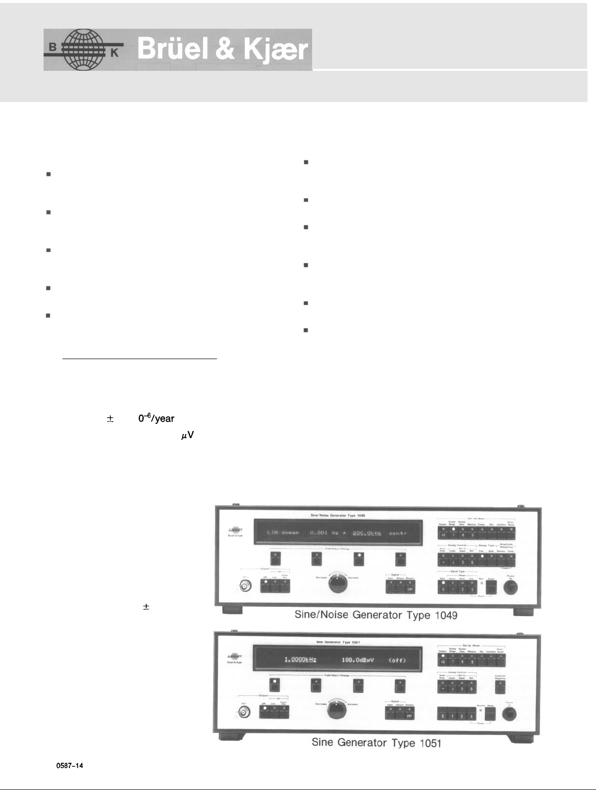
types 1049 and 1051
Sine/Noise Generators
USES:
Precision ATE signal generators for use in
computer based test systems, requiring a high
accuracy, low distortion excitation source
Semi and fully automatic test and calibration of
electrical and mechanical equipment for product
design, development, production and service
Swept-frequency electro- and building-acoustic
measurements; vibration testing of mechanical
components; plus audiological research etc.
Storage of amplitude weightings for equalizing
flat loudspeaker, vibration exciter responses etc.
Remote control of Level, X-Y and Graphic
Recorders for synchronous recording of amplitude, phase and distortion responses
FEATURES:
n
0,2
to 200000 Hz, sine generators with frequency
resolution down to 1
mHz
and clock stability
better than
n
Calibrated output from 100
than -96
n
Six-decade frequency sweep in one continuous
dB
harmonic and spurious distortion
to 5V with less
range with selectable lower and upper limits
non-
Choice of linear and logarithmic frequency sweep
with sweep rates from 0,001 Hz to
and 0,001
mDec
to 2
Dec/s
respectively
999,9
kHz/s
Single, repetitive (l-99) and continuous sweep
modes with
0,O1
to
100,0
s pause between sweeps
1024 point amplitude memory, with automatic
amplitude interpolation, for preconditioned test
excitation
40 character, alphanumeric, line display for monitoring and setting-up of frequency and amplitude
sweep parameters etc.
9 set-ups for recalling frequently repeated excitation test and measurement sequences
Versatile IEEE/IEC bus for remote control and
digital output of data
ADDITIONAL FEATURES 1049:
n
Narrow-band random, white and pink noise modes
n
Logarithmic amplitude sweep with sweep rates
from
0,O1
to 999
n
118 dB compressor circuit for active control of
dB/s
sound or vibration level at exciter output
n
Automatic learn mode for amplitude memory, via
compressor
The B&K Types 1049 and 1051 are
two microprocessor-based sine generators which combine today’s needs of
increased spectral purity, frequency
resolution and stability with ease of
use and versatility. Their wide frequency coverage from
kHz,
200
frequency resolution of
1
merous applications in electronic engineering, as well as in acoustics and
vibration measurements. Linear and
logarithmic sweep ranges, each with
their own user-presettable lower and
upper limits may be chosen, including
extended linear sweeps from 0,001 Hz
to 200
tinuous sweep modes are also included
and the time for each individual sweep
is automatically calculated and displayed.
BP 0587-14
with amplitude linearity and
mHz,
make them suitable for nu-
kHz.
Single, repetitive and con-
0,2
Hz to
0,05 dB
and
Page 2
Speeder
r------
LOG sweep
_
Line Display
Front Panel Controls
Control
1
I tt
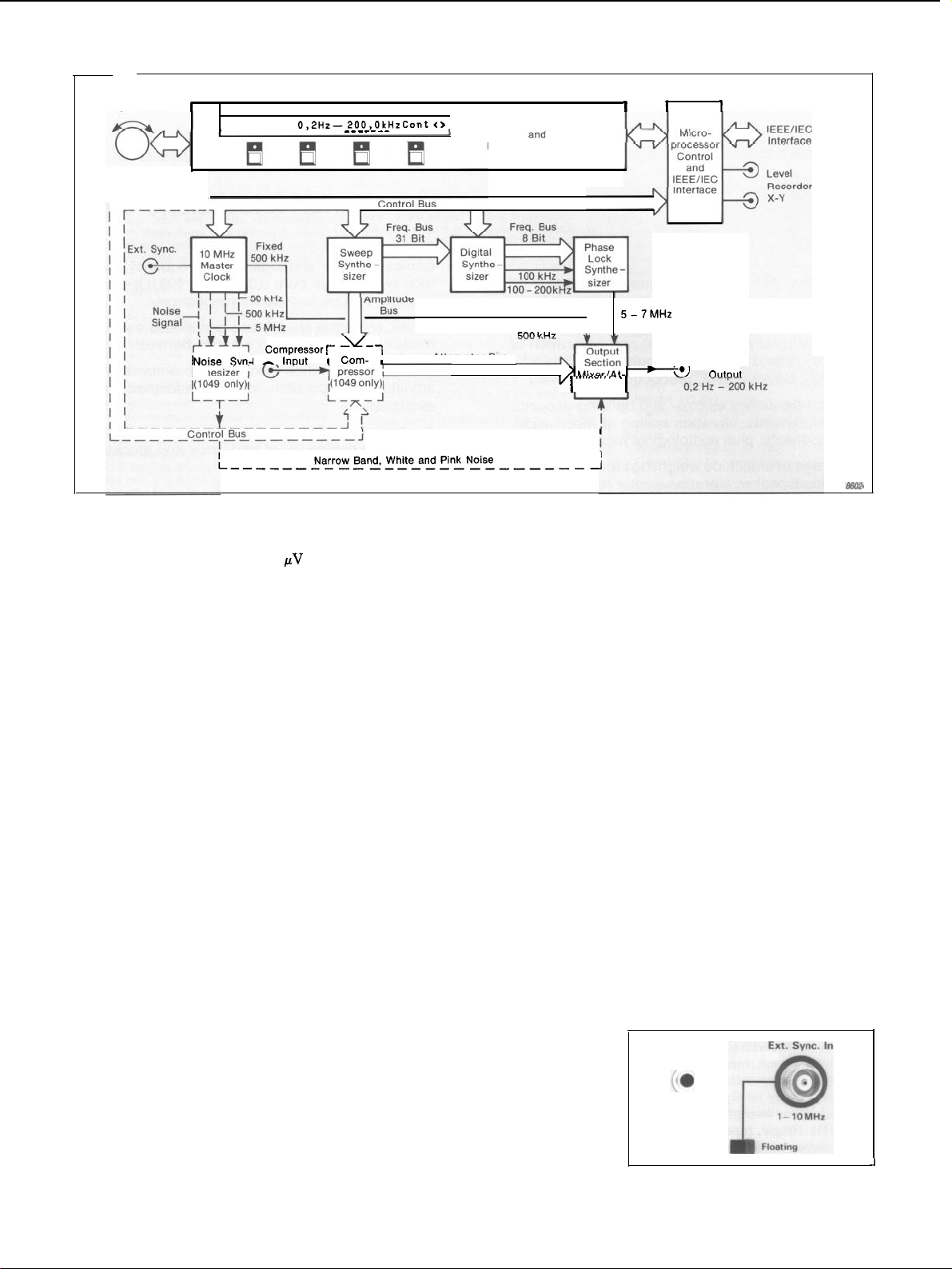
Fig. 1. Simplified block diagram of the B&K Sine/Noise Generator
Outputs levels from 100
5
V RMS may be chosen to 3 digits,
Inout
Narrow Band White and Pink
to
permitting either a constant amplitude or an amplitude-weighted, fre-
IEEE/IEC system controller is used
for automatic control of the Generators, they may be coupled with a digital plotter.
Attenuator
quency sweep to be obtained. With
the latter up to 1024 amplitudes may
be stored, which enable the Generators to simulate the output of record
reproducer pick-ups, tape heads and
electrical circuits etc. Also, equalization characteristics can be stored for
maintaining a constant sound pressure
or vibration output with loudspeakers
and vibration exciters.
In addition to the above, the Type
1049 has a number of extra facilities.
These include a logarithmic amplitude
sweep, as well as narrow-band random, white and pink noise outputs.
Also, a compressor circuit is built in as
an alternative means of obtaining a
constant sound or vibration level output when a loudspeaker or vibration
exciter is employed with the genera-
All functions and parameters may
be selected or entered by the front
panel
pushkeys
or via the IEEE/IEC
digital interface bus of the Generators.
In addition, there is an analogue
“speeder” knob for fast and precise
continuous adjustment of parameters.
tor. In this case, however, external
feedback is employed to provide active regulation of the generator output
which has the benefit that it automatically takes into account the response
of the exciter under actual test condi-
tions.
Front panel set-up conditions are indicated on a 40-character line display,
from which as many as four functions
Description
and their individual parameters may
be monitored simultaneously.
A simplified block diagram of the
B&K Generators Types 1049 and
If desired, nine sets of front panel
set-up conditions may be stored and
instantly recalled for performing frequently used excitation test and measurement sequences, as is normally
called for in service and production
testing of products. For automatic
plotting of swept-frequency measurements and analyses, special provision
is made for synchronizing level and
Y recorders. Alternatively, where an
1051 is shown in
main sections, namely a Master Clock,
a Digital Frequency Synthesizer, a
Phase Lock Synthesizer, a Sweep Synthesizer and an Output Section, all of
which operate under the guidance of a
Microprocessor Section which takes
care of the user communication via
front
the
IEEE/IEC interface of the Genera-
X-
tors. In addition, Type 1049 features a
Fixed
Bus
ten /Amp
I
Noise
Type
1049 and Sine Generator Type 1051
Fig.1.
They have 6
panel
controls
I
and
Variable
A
Generator
Noise Generator and Compressor,
which greatly increase its range of
applications, especially for acoustic
and vibration measurements.
Frequency Synthesizer
The Generators employ a
heterodyne synthesis technique where a
500
kHz
fixed frequency is mixed with
a 500 to 700
kHz
variable frequency to
produce an 0,001 Hz to 200
swept-frequency,
sine-wave output
with frequency resolution of 1
The 500
kHz
fixed frequency is obtained from a Master Clock, while the
500 to 700
kHz
variable frequency is
derived from the 5 to 7 MHz output of
a Phase Lock Synthesizer.
The Master Clock is based on a stable 10 MHz crystal oscillator whose
relative accuracy is transferred to the
output frequency. If an even greater
accuracy is required the internal oscillator can be phase locked with an
external reference which may be coupled to an External Synchronization
i
Chassis
Fig. 2. External Synchronization Input of
the 1049 and 1051 Generators
kHz
mHz.
2
Page 3
Input socket on the rear panel. See
Fig. 2.
For a 5 to 7 MHz variable frequency
proportional to the generator output
frequency, a 31 bit frequency control
output from the Sweep Synthesizer is
utilized. To achieve a wide sweep
range while maintaining a high accuracy and resolution, the Sweep Synthesizer output is split into two components. The lowest 23 bits are used
to produce a 100 to 200
kHz
variable
control frequency proportional to the
mHz
Hz and
frequency setting of the
Generators, while the remaining 8 bits
are used to produce a
69,9
MHz control frequency propor-
kHz
tional to the
setting.
49,9
to
the mixed signal, a 280
filter is employed.
Before application to the outputs of
the Generators the filtered sine-wave
signal is fed to an attenuator and
amplifier for amplitude conditioning.
The output attenuator gives an overall
attenuation of 16 bits enabling the
fraction and exponent of the output
level to be accurately set within 3
digits from 100
the front panel controls and interface
bus of the Generators.
The Output Amplifier provides two
low impedance signal outputs, which
are made available at a BNC socket on
the front and rear panels. These may
be matched with 50
The respective control frequencies
are generated by a digital synthesis
and a divide by “N” phase lock loop.
They are then summed by another
to suit different test system grounding
requirements, may be isolated or connected to chassis by means of a slider
switch on the rear panel. See Fig.3.
phase lock loop to produce a 50 to
70 MHz control frequency which after
1O:l
application to a
frequency divider
in the Phase Lock Synthesizer is fed
to the Output Section where the final
stages of frequency conversion take
place. The use of two phase lock loops
for producing 50 to 70 MHz control
frequency, ensures that phase noise is
kept to a minimum.
In the design of the Generators,
particular attention has been paid to
obtaining very low signal distortion
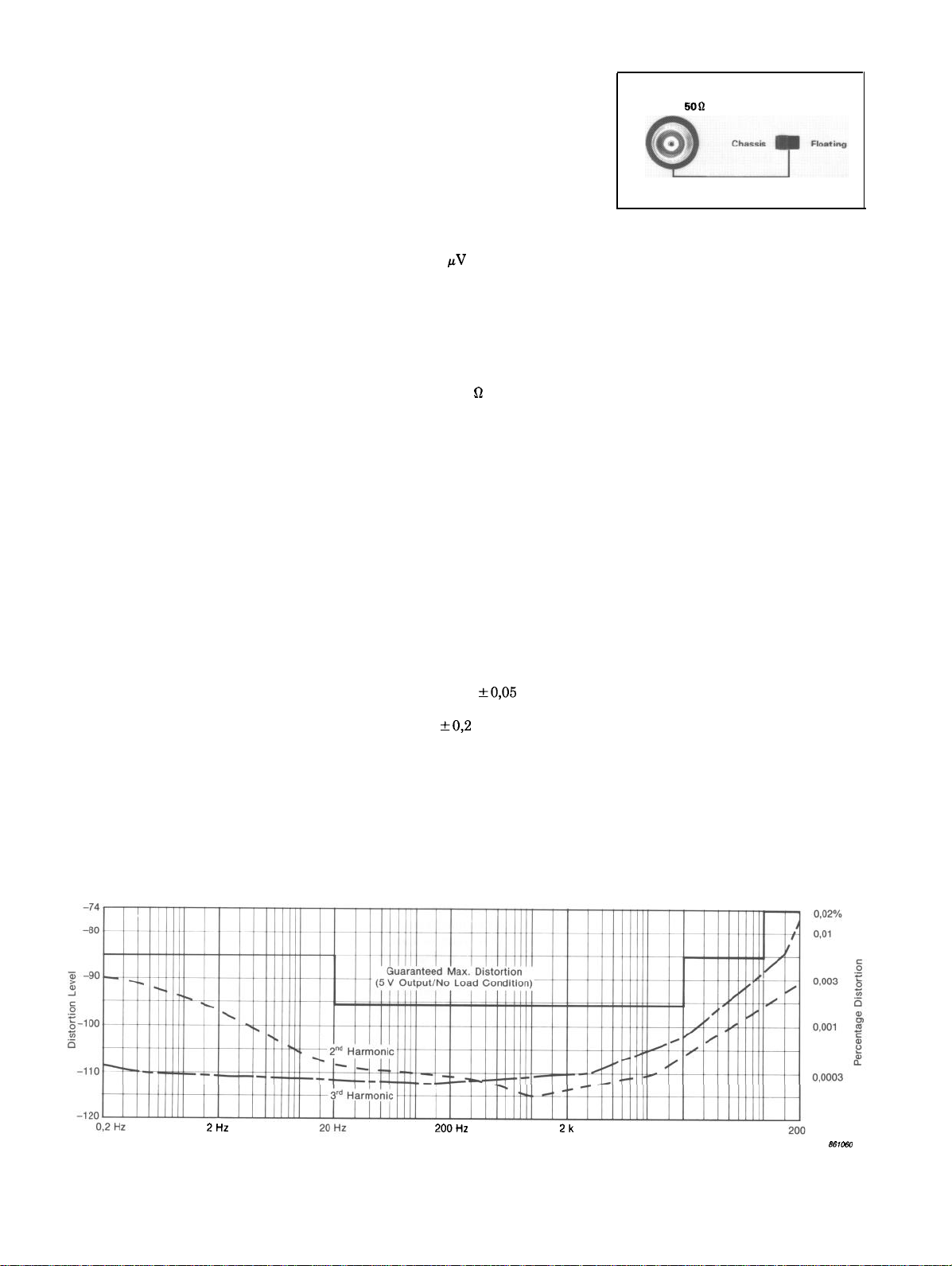
and good amplitude linearity. As indicated in Fig. 4 the maximum harmonic
and spurious distortion is guaranteed
better than -96 dB at frequencies between 20 Hz and 20
and third harmonic distortion components typically
Output Section
From the Phase Lock Synthesizer
the 5 to 7 MHz control frequency is
10:l
applied to a second
frequency
divider which is included at the input
of the mixer stage of the Output Section. The output is then mixed with
kHz
the 500
output of the Master
Clock to produce a sine-wave signal
whose frequency corresponds directly
to the frequency indicated on the display of the Generators. For removing
unwanted side-band components in
The amplitude linearity of the output is better than
quencies between 20 Hz and 20
decreasing to
200
kHz.
plitude falls by 20 dB per decade, but
by utilizing the “Memory Learn” function of the Generators to maintain a
constant output level of 300
less, a flat amplitude characteristic
can be maintained at all frequencies
down to 0,001 Hz.
kHz
low-pass
to 5,00 V RMS via
signal lines and
kHz,
with second
-1l0dB
down at 1
dB
kHz.
at fre-
kHz,
dB at
0,2
Hz and
At lower frequencies the am-
mV
or
output
Fig. 3. BNC Output and Chassis/Floating
switch of the 1049 and 1051
Sweep Synthesizer
The Sweep Synthesizer includes a
ramp register which produces a 31 bit
output representing the frequency setting of the Generators. The frequency
may be set by an input either from the
front panel keyboard or via the interface bus of the Generators. For a frequency sweep, however, an internal
clock signal is used, enabling either
“Linear” or “Logarithmic” frequency
sweeps to be chosen with sweep rates
from 0,001 Hz/s to
0,001
mDecade/s
to 2 Decade/s, re-
999,9 kHz/s
and
spectively.
With linear and logarithmic frequency sweeps, six or more complete
frequency decades can be covered in a
single range. The logarithmic sweep
range extends from
200
kHz,
while the linear sweep range
is from 0,001 Hz up to 200
0,2
Hz up to
kHz,
however, either can be independently set
to any lower or upper frequency limit
within these ranges if so desired.
In addition to the above, “Up”,
“Down”, “Up/Down”, “Single”, “Repetitive” (1 to 99) and “Continuous”
sweeps modes may be chosen. Also
there is a “Pause” function whereby a
preset delay of between 0 and 100 s
may be included between each consecutive sweep.
Fig. 4. Typical and
frequency range from 2 Hz to 200 kHz
maximum
20k
Frequency Hz
guaranteed distortion levels produced by the 1049 and 1051 Generators (5 V output, no load condition) in the
0.0001
k
3
Page 4
A convenient feature is that the
Generators automatically compute the
time for a single sweep. The sweep
time is indicated directly on the front
panel display and automatically takes
into account the particular frequency
limits and sweep rate chosen. With
single and repetitive Up/Down sweeps
a minimum sweep time of 8 ms can be
achieved, while with sweeps including
pause or single sweeps in one direc-
tion, sweep times as short as
62,5
are possible.
Because the frequency sweep of the
1049 and 1051 is rate based a higher
sweep accuracy can be maintained.
With generators which are programmed with respect to time the sweep
accuracy is generally lower, particularly with logarithmic sweeps.
Amplitude Memory
Besides a ramp register for frequency synthesis, the Sweep Synthesizer
contains an amplitude register for
controlling the Output Section Attenuator.
For manual setting of the output
level, the amplitude register accepts a
numeric input from the front panel
keyboard or a digital input applied
over the interface bus of the Genera-
tors. The input may be applied direct-
ly to the amplitude register or, if the
“Memory Learn” function is used, via
the internal memory of the Generators. In the latter case, up to 1024
amplitudes can be stored for successive frequencies within any desired frequency range of the Generators, and
when recalled enable almost any type
of single or repetitive, amplitude
weighted, frequency sweep to be generated.
The “Memory Learn” function is of
particular benefit for swept frequency
sound and vibration measurements.
When one of the Generators is employed to drive a loudspeaker or vibration exciter, for example, its output
level can be weighted according to the
dynamic response of the loudspeaker
or vibration exciter so that a constant
sound pressure or vibration level output is maintained over the entire frequency range of interest.
To save entry of each individual
level manually, the “Memory Learn”
function includes automatic ampli-
tude interpolation between consecu-
tive amplitudes input. Alternatively,
amplitudes may be entered as a voltage signal via the Compressor Input of
the 1049.
Additional Features
Type 1049
Noise Generator
In the Sine/Random Generator
Type 1049 wide band, pseudo random
noise of very even spectral density is
generated by two long shift registers
followed by a low- and high-pass filter.
The noise signal has a symmetrical
gaussian
4,5 with upper frequency limit, line
spacing and sequence length depending on the shift register clock frequency. See “Specifications”.
-0,5 dB lower and upper frequencies
of the filters, nine combinations of
white noise can be obtained, ranging
from 2, 20 or 200 Hz up to 2, 20 or
200
shev types giving less than 0,l
ripple and an 18 dB/octave low- and
high-frequency roll-off. For a pink
noise output over the same frequency
ranges, the white noise signal is fed
through a -3 dB/octave filter before
being applied to the attenuator and
amplifier stages of the Output Section.
band noise output, the white noise
signal is fed to a balanced modulator
circuit. This produces two DC to
1,25 kHz
phase of 0 and
to two identical low-pass filters. The
filters are
which have a high frequency attenuation slope of 18
table cut-off frequency of exactly half
the particular noise bandwidth chosen
on the Generator.
signals are mixed and summed to
produce two complementary signals
which on an amplitude basis represent
each half of the narrow-band noise
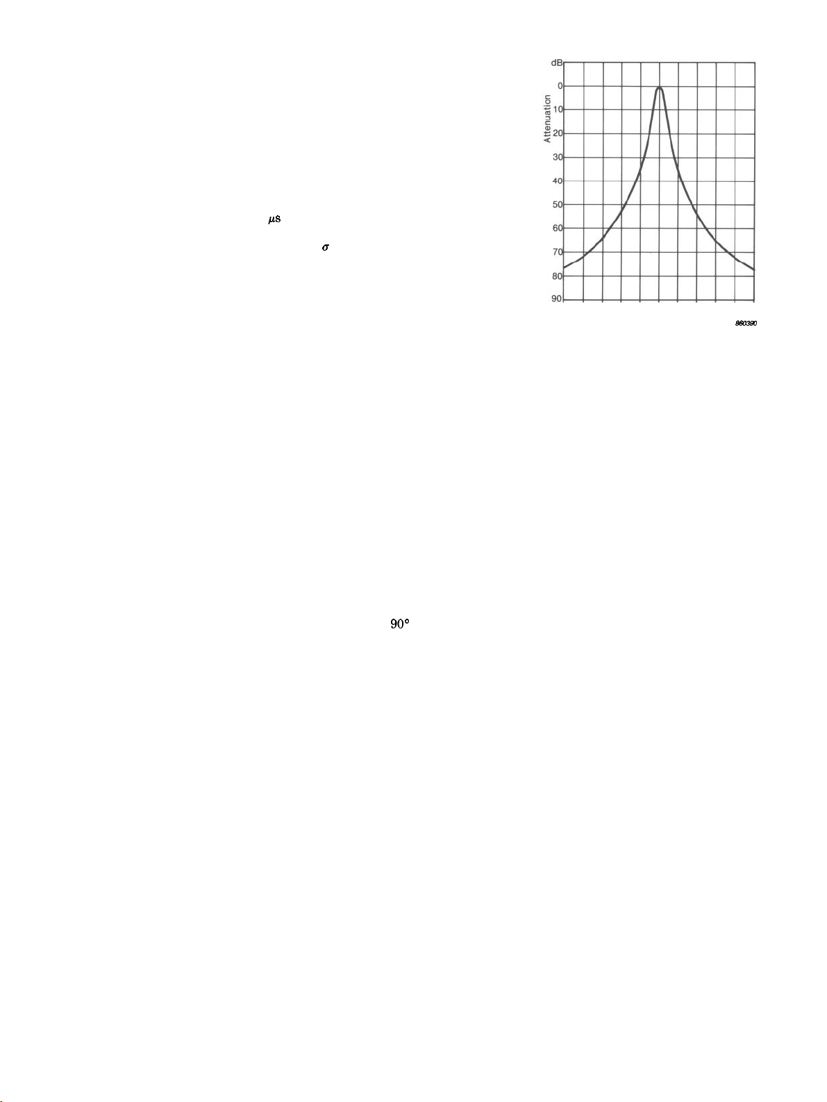
characteristic shown in Fig. 5, but with
centre frequency of 500
signals are then combined and fed to
the 500 to 700
Output Section where they are converted to a swept-frequency, narrowband, noise output operating over the
same sweep range as the sine-wave
output of the Generator.
the narrow-band, white and pink noise
generated by the 1049, the noise is
attenuated by 12
respect to the sine output. The
amplitude distribution up to
selecting
B
Y
kHz.
The filters are
the
appropriate
3-pole Chebi-
For a swept-frequency, narrow-
noise signals with relative
which are applied
3-pole
Butterworth type
dB/octave
with selec-
From the low-pass filters the two
kHz.
The two
kHz
mixer stage of the
Because of the high crest factor of
dB
(factor of 4) with
gener-
dB
-10 -6 -6 -4 -2 0
Bandwidths from centre frequency
Fig. 5. Pass band of the 1;
and 316 Hz narrow-band noise
bandwidths of the 1049
ator
automatically accounts for this,
2
3,16;
4 6
10;
31,6;
8 10
100
so that the exact output level in the
noise as well as the sine modes is displayed.
Compressor
As an alternative means of maintaining a constant output level with a
loudspeaker or vibration exciter, the
1049 includes a Compressor. This enables a “live” control signal from an
external preamplifier and measurement transducer to be used to automatically regulate and weight the output level of the Generator according to
the dynamic characteristics of the
loudspeaker or vibration exciter under
actual test conditions.
The Compressor comprises an Input
Attenuator and RMS Detector, followed by a VCO and Voltage Comparator. The VCO is used to produce a
variable-frequency clock signal which
is proportional to the rate of change of
the input signal and is fed to the amplitude sweep register for automatic
control of the Output Attenuator. The
decision as to whether an increasing or
decreasing amount of compression is
needed to maintain a constant excitation level is made by the Comparator,
which actuates the up/down input of
the amplitude register.
The Compressor is equally adept at
regulating the random noise as well as
sine-wave outputs of the 1049 and
gives no regulation error when dwelling at a single frequency. In both
modes regulation over a 118 dB range
is achieved, relative to a maximum
output level of 5 V RMS.
4
Page 5
The amount of compression is adjustable over a wide range using the
Input Attenuator and either the input
level or the amount of compression
can be monitored directly on the 1049.
For regulating low frequency signals
without distorting the signal waveform, as well as counteracting excitation peaks of loudspeakers and vibration exciters, there is a choice of eight
compressor speeds ranging from
1000 dB/s.
0,3
to
Amplitude Sweep
Also available with the 1049 is a
logarithmic amplitude sweep. This
may be chosen in place of a
sweep and is useful for investigating
the electrical limiting and delimiting
characteristics of audio recording and
reproducing equipment, plus studying
the dynamic behaviour of loudspeakers, earphones and telephone handsets. For these applications, either the
random noise or sine output may be
employed and the output level swept
up and down with a sweep rate be-
0,Ol
tween
As with the Compressor, the amplitude sweep is obtained by utilizing the
amplitude register of the Sweep Synthesizer to automatically step the Output Section Attenuator of the 1049. In
this case, however, a separate clock
signal is applied whose frequency
determines the particular sweep rate
selected. The amplitude resolution of
the sweep is better than 0,l
and 999 dB/s.
frequency
dB.
Monitoring and
Set-Up Adjustments
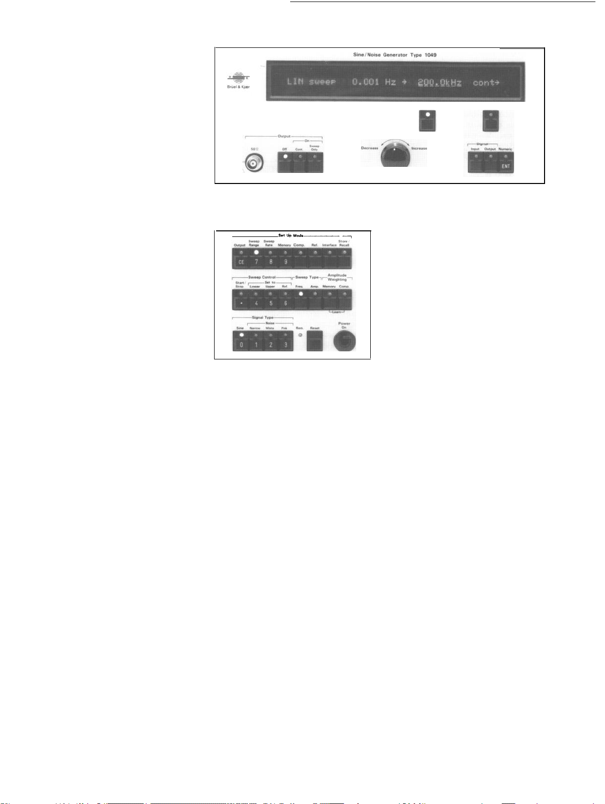
Display and Field Entry
For convenient setting-up and monitoring of control settings, frequency
sweep and output voltage limits etc.,
the front panel is furnished with a
character vacuum fluorescent line display plus a keyboard for selection of
set-up and operating modes (see
Figs.6 and 7). Depending on the par-
ticular set-up and operating mode
chosen, the display is capable of indicating as many as four control settings
simultaneously which also makes it
useful for monitoring control parameters during the course of measurements.
Just below the display are four Field
Select keys for selecting control settings to be changed. These may be
used either to select and set a particular control setting directly, enabling a
linear sweep to be changed to a
40-
loga-
Fig. 6. Vacuum fluorescent line display, plus the field select and speeder controls of the 1049
and 1051
Fig. 7. The Setup Mode, Sweep and
keys of the 1049
rithmic sweep for example, or for increasing the number of digits by which
the frequency may be entered using
the numeric
the front panel. Alternatively, the fre-
quency and amplitude limits may be
altered by employing the Speeder
knob which is located beneath the
Field Select keys.
The Speeder emulates the function
of the coarse and fine tuning knobs of
analog types of generator. Turning the
knob a fraction to the left or right
gradually decreases or increases the
displayed value for the function selected with the Field Select keys,
while a proportionately larger turn
increases the speed at which the
displayed value is altered.
Operating Set-Ups
When first switched on the Genera-
tors are automatically set to the control settings selected during previous
use. The settings are stored in a continuous memory which is capable of
storing 9 complete sets of front panel
settings or setups so that a number of
exciter control programmes may be
kept on hand for performing frequent-
ly repeated swept frequency tests and
measurements.
pushkeys
on the right of
Signal
The individual setups may be instantly recalled whenever desired,
simply by entering their set-up number. Provided that the memory back-
up battery is kept charged by subject-
ing the Generators from between 2 to
4 hours use per week, then the set-ups
may be retained indefinitely. See the
“Specifications” section.
If required an entire setup may be
copied in another setup so that only a
limited number of control settings
changes need be made to obtain a new
setup suited to a specific test or task.
Where more than 9 setups are required, they may be stored externally
using a digital tape or disk station and
input over the digital interface of the
Generators.
Interfacing
Digital Interface
The digital interface of the 1049 and
1051 conforms with the IEEE Std.
488-1978, and is fully compatible with
the IEC 625-l standard. It may be
interconnected with as many as 15
separate instruments at one time, thus
enabling numerous, fully integrated,
ATE (automated test equipment)
systems to be built which may be
operated via a desk-top calculator,
computer or purpose built controller.
The interface has a full Talker (T5)
and Listener (L3) capability, permitting remote sensing and selection of
the generator controls, plus printing of
the control status. As with other B
instruments,
easy to interpret acronyms as well as
complete control names for commands, thus enabling users to setup
their own fully automatic control
sequences with the minimum of programming experience.
the interface accepts
& K
5
Page 6
Recorder Interface
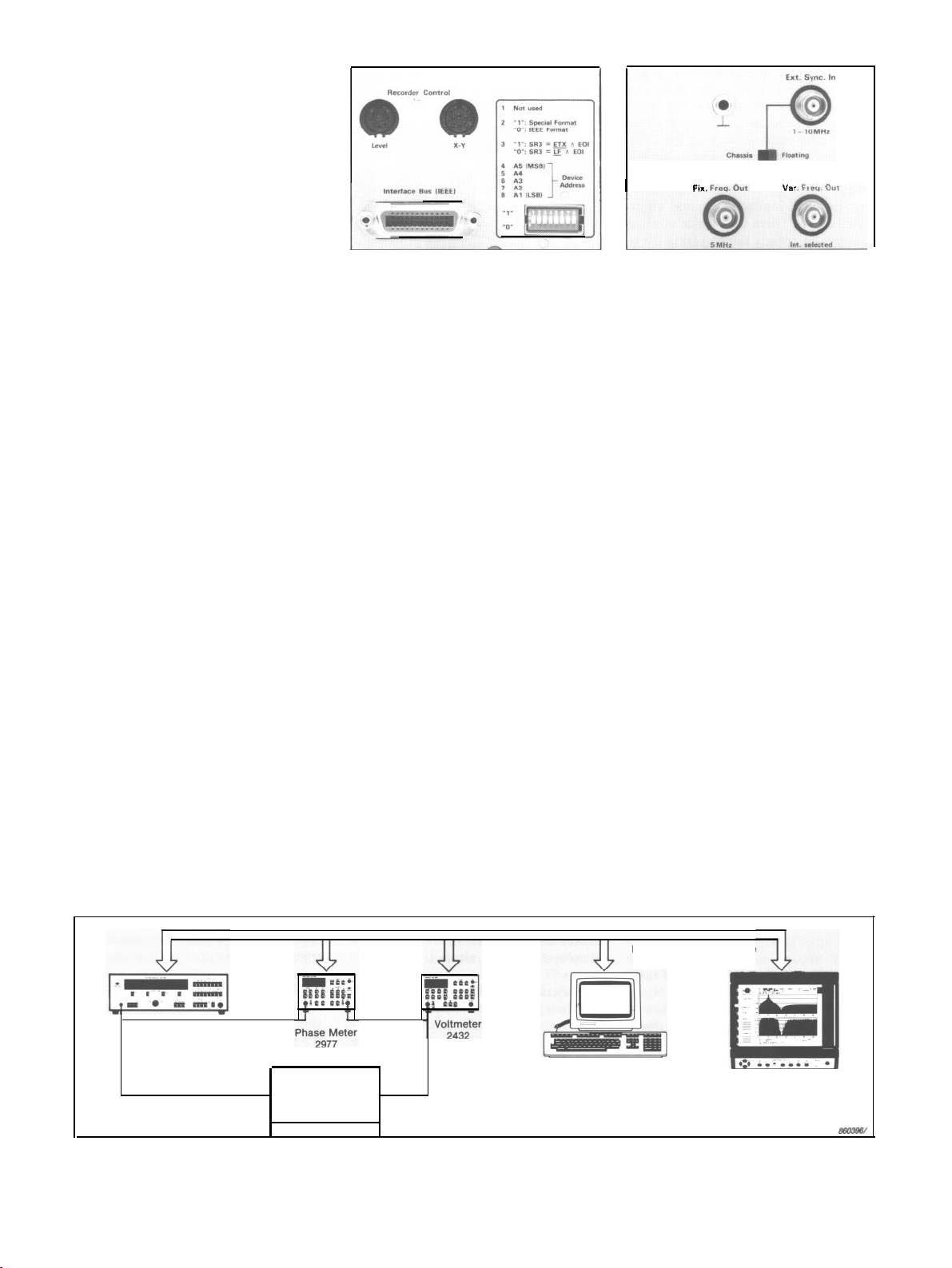
For graphic recording of swept frequency tests and measurements analog outputs are available for coupling
level or X-Y recorders. These are
shown in Fig.8 and provide the necessary control voltages for
synchronous
recording over a maximum of six frequency decades with either the B&K
Level Recorder Type 2307 or X-Y
Recorder Type 2308.
With X-Y Recorders, recordings can
be made on linearly or logarithmically
graduated paper, irrespective of which
type of frequency sweep is chosen on
the Generators. Also plotting of forward and reverse frequency sweeps is
possible and for tape recorder and
acoustic investigations the X-Y synchronization can be delayed between 0
and 1 s in 10 ms steps to coincide with
the arrival of the measured signal. For
continuous monitoring of measurements the wide choice of sweep rates
of the Generators enable the X-Y output to be used to control an oscilloscope.
Auxilliary Outputs
Supplementing the sine-wave and
noise outputs of the Generators is a
square wave output. This provides a
1
mHz
to 200
kHz
TTL signal corresponding with the frequency setting of
the Generators which will be found
ideal for pulse testing of electronic
measuring, recording and reproducing
equipment.
Also available with the Generators
are a fixed frequency (5 MHz) and a
Fig. 8. The Recorder and Digital Interface
connectors of the 1049 and 1051
variable frequency (5 - 7
MHz/50 70 MHz user selected) output which
may be used as clock references for
external equipment.
Synchronization Input
For locking the internal clock of the
Generators with an external source, a
Synchronisation
Input is provided
which accepts a 10 MHz signal or an
appropriate
sub-harmonic.
See
“Specifications”.
Examples of Use
Because of their high performance
capability and extreme operating flexibility, the Sine/Noise Generator Type
1049 and Sine Generator Type 1051
can be used for a very wide range of
applications.
Fig. 9. The Fixed and Variable Freq. Out-
puts, plus the External Synchroni-
zation Znput of the 1049 and 1051
Their wide frequency and dynamic
ranges, high accuracy, resolution and
stability, plus extensive remote control possibilities via a standard
IEEE/IEC digital interface, make
them an ideal ATE signal source for
electronic design and development
work, quality control, production test
and service of a wide variety of electrical products. In addition, the noise
output and compressor facilities of the
1049 will find extensive applications
in electro-acoustic and building acoustic investigations, as well as in vibration testing of mechanical components
and structures.
For use of the 1049 and 1051 as part
of a larger measurement system
& Kjær
markets a range of analogue
Brüel
and digital equipment. These include
the Digital Voltmeter Type 2432, Dig-
IEEE/lEC
Interface
Sine Generator
1049/1051
,
Electronic
Device under
Test
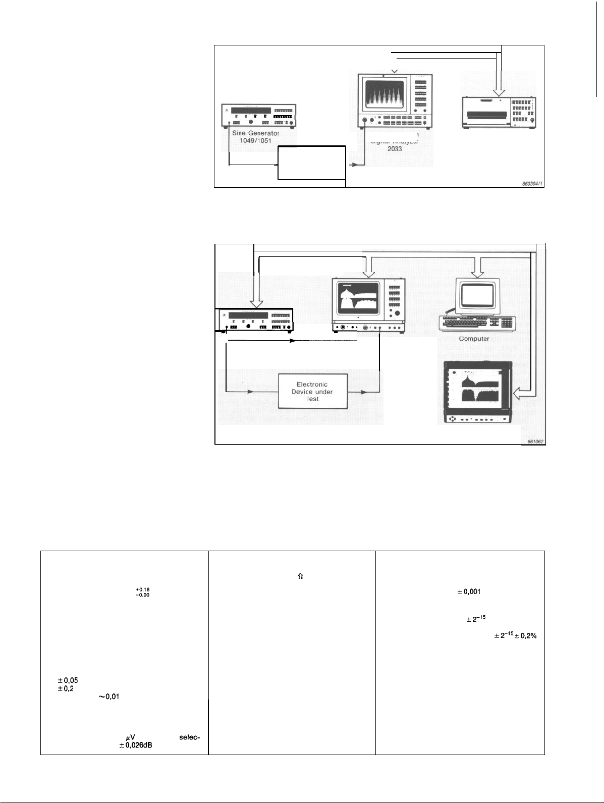
Fig.
10. Automatic test arrangement for frequency response measurements (amplitude and phase) on electronic equipment. Using their internal memory for preconditioning, the 1049 and 1051 Generators can simulate a record pick-up, tape head, preamplifier equalization
network output etc.
Computer
Cable
Graphics Plotter
2319
Page 7
ital
Phase Meter Type 2977, High
Resolution Signal Analyzer Type 2033
and Dual Channel Signal Analyzers
Type 2032 and 2034 - all of which are
especially designed for a wide variety
of response measurements and fre-
quency analyses. For storage and
documentation of results the Digital
Cassette Recorder Type 7400, plus
Graphics Recorder and Plotter Type
2313 and 2319 are available. Some
typical examples of the use of these
instruments with the Generators are
shown in Figs.10 to 12.
As with the Generators, all the
digital equipment mentioned can be
controlled via a computer or purpose
built system controller which features
an IEEE/IEC interface. This makes
them ideal for use in laboratory, production and environmental testing
where very many performance tests
and calibration checks have to be
carried out which are of a repetitive
nature. Here it is useful that tests are
carried out on an automatic basis using a computer or system controller to
control the entire test setup. Also, a
computer can be used for reformatting
measured data to produce a hardcopy
readout of frequency, phase and amplitude responses etc., with a graphics
recorder or plotter. In more advanced
systems a computer may be used to
decide on whether test results are
within acceptable limits as well as to
diagnose faults.
For further details on the B&K
equipment mentioned, please consult
the B&K Short-Form or Master
Cata-
logues.
IEEE/IEC
Interface Cable
Electronic
Device under
Test
1
High-Resolution
Signal
Analyzer
Graphics Recorder
2313 + Application
Package
BZ
7002
Fig. 11. Harmonic distortion measurements using the 1049 or 1051 Generator with the 2033
High-Resolution Signal Analyzer
IEEE/IEC
Interface Cable
Dual Channel
Sine Noise Generator
1049
Fig. 12. Automatic test arrangement using the 1049 Sine/Noise
Signal Analyzer
2032/2034
Graphics
2319
Generator
Plotter
with the 2032 or
2034 Dual Channel Signal Analyzer for transfer function and distortion measurements on electronic equipment. Using the amplitude sweep function of the 1049 the
attach and release time of compressor/expander circuits
and
other non
linear
equip-
ment may be measured
SINE GENERATOR:
Frequency Range:
generator can be used at frequencies down
to 0,001 Hz. See “Amplitude Linearity”
Frequency Resolution: 1 mHz
Frequency Stability:
40°C with <5 ppm aging per year
Harmonic and Spurious Distortion:
(-96 dB
within 20 Hz to 20
<-85 dB
within
<-75 dB
Phase and A.M. Noise:
over 200
rejection band centered on output frequency
Amplitude Linearity:
GENERATOR OUTPUTS:
Via BNC sockets on front and rear panel
Output Voltage: 100
table to 3-digits with
within 100
kHz
dB
from 20 Hz to 20
dB from
-3 dB
limit
attenuation slope down to 0,001 Hz
0,2
Hz to
2OOkHz.
The
Spec.
<25
ppm from 10 to
kHz
to 200
<-85 dB
to 5 V RMS
kHz
kHz
kHz
measured
kHz
kHz
relative atten-
0,2
Hz to 100
range with 5 V output and 1 Hz
0,2
Hz to 200
Hz with 20 dB/decade
Specifications
uator accuracy. Output readout based on
load condition
Output Impedance: 50
Grounding: Chassis/Floating (0,1 V max.)
OUTPUT On/Oft
<O,1
Fast:
Slow:
output signal 60
AMPLITUDE MEMORY:
1024 amplitudes can be memorized within
any given frequency range and later recalled
for successive single or repetitive amplitude
weighted frequency sweeps. Amplitudes may
be input numerically via the front panel
keys, digitally via the IEEE/lEC interface or
as a voltaae input to the 1049 compressor.
Includes automatic amplitude interpolation
between consecutive amplitudes input
FREOUENCY SWEEP:
Linear/Logarithmic with or without amplitude
weighting from amplitude memory
ms rise and decay time
-30 ms for raising and suppressing
1049/1
dB
051
no-
push-
Sweep Limits: from
table to 4 digits. In extended range 0,001 Hz
kHz
to 200
reached within the resolution of the programmed stop frequency
Sweep Rate:
Sweep Resolution:
Sweep Modes: Up, Down, Up and Down,
gle, Repetitive 1 - 99 times and Continuous
are selectable
Amplitude Weighting: 1024 amplitude levels
can be played back during the frequency
sweep. See “AMPLITUDE MEMORY”
linear sweep. The limits will be
Linear: 0,001 Hz/s to
table to 4 digits with
Logarithmic: 0,001 mDec/s to 2,000 Dec/s
selectable to 4 digits with
per Dec/s accuracy
Linear:
<0,244
Hz at rate
Logarithmic:
Dec/s
or frequencies <1
outside the above limits
<1 mHz
0,2
Hz to 200
at rate
>4,788
<1 mHz
Hz
999,9
accuracy
<4,768
kHz/s
at rate
kHz.
kHz,
selec-
kHz/s selec-
kHz/s or
<8,089m-
0,244 Hz
Sin-
Spec.
7
Page 8
Sweep Pause:
repetitive sweeps, selectable with 10 or
100 ms resolution and 1 ms accuracy
Pause Output: Output may be set “On” or
“Off” between repetitive sweeps
Control Limits: Sweep on may be individually
preset to reference or any preset lower and
upper frequency or amplitude limit dependent
on sweep type
Sweep lime: Computes and displays time
for single sweep between particular lower
and upper limit and sweep rate selected.
Minimum single sweep time is 8 ms for repetitive Up/Down sweeps and
including pause or single sweeps in one
rection
LINE DISPLAY:
40-character, vacuum fluorescent, line
play with 4 display fields for entry and
age of generator control settings, as well as
simultaneous monitoring of generator output
frequency, output voltage, compressor
age, etc.
TEST PROGRAMMES:
Non volatile memory for storage of front panel control settings. Enables 9 user-defined
control sequences to be stored and instantly
recalled for electronic, electro-acoustic and
vibration test work. For continuous storage of
control settings the Generators must be
0,00
to
100,0
s pause between
dis-
stor-
volt-
sub-
di-
jected to 2 to 4 hours use per week.
AUXILIARY INPUTS/OUTPUTS:
Via separate BNC sockets on rear panel
Square Output: TTL square wave output of
generator frequency from 1
Ext. Sync. In: For phase locking internal
clock with external signal source
Input Freq: 10 MHz down to tenth sub-har
-monic
Input Voltage:
Tuning Range:
Ground: Chassis/Floating (0,1 V max)
Fix. Freq. Out: 5 MHz square-wave output
reference frequency
Output Voltage:
Output Impedance: 200
Var. Freq. Out: User selected 5 to 7 MHz or
50 to 70 MHz output depending on generator
0,6
100 ppm
0,6
mHz
to 200
to 30 V Peak-to-Peak
V Peak-to-Peak
kHz
frequency
Output Voltage:
Output Impedance: 25
Sweep Start: TTL output for trigger
ing
0,6
V Peak-to-Peak
record-
RECORDER INTERFACE:
Level Recorder: 7-pin DIN socket providing
remote control of start, stop, automatic stop
and pen lift
8-pin
DIN
socket
X-Y Recorder:
mote control of pen lift and X-deflection
Voltage Ramp: 0 to 10 V for X-deflection 12
bit D/A Converter. Linearity 10 bit. 200 Hz
sample frequency
Ramp Voltage Limits:
Lin. or Log. voltage ramp selectable for either
Lin. or Log. frequency sweep
Lin. Ramp: 0 to 10 V for any lower or upper
frequency limit from 0 Hz to 200
fixed limits of 0 Hz to 200 Hz, 0 Hz to 2 kHz.
0 Hz to 20
Log. Ramp: 0 to 10 V ramp for any lower or
upper frequency limit from
200
2 Hz to 2
to 200
Amp. Ramp (1049 only): 0 V to 10 V for
any lower or upper amplitude limit from
40 to
kHz
and 0 Hz to 200
kHz
or fixed limits of
kHz,
20 Hz to 20
kHz
140 dBpV
Ramp Delay:
resolution down to
IEEE/IEC
Conforms to IEEE 488 and IEC 625-l
dards. Connection into an IEC interface
tern is made using cable A0 0264 or cable
A0
0194 and Adaptor A0 0195. Connection
into an IEEE interface system is made using
cable
Functions Implemented: Source Handshake
1).
(SH
(T 5).
Listener (L 3). Service Request (SR
Remote Local (RL
vice Clear (DC
troller (C 0)
Data Ouput: Generator frequency, output
el etc., plus all front panel control settings
0,00
to 1
0,O1 s
DIGITAL INTERFACE:
A0
0265.
Acceptor Handshake (AH
1),
Parallel Poll (PP 0),
1).
Device Trigger (DT I), Con-
providing
0,2
Hz to 200
kHz
and 80 to
,OO s
selectable with
and 200 Hz
kHz
0,2
l),
kHz
Hz to
kHz,
stan-
sys-
Talker
lev-
re-
or
De-
Remote Control: All functions and instrument
front panel settings can be remotely
trolled via the digital interface.
/frequency can be set with full resolution in
less than 20 ms Binary (30 ms ASCII) format
IS0
Code:
7 bit code
con-
Amplitude-
GENERAL
Warm-Up lime: -20 minutes
Temperature Range:
Operation: 10 to 40°C (50 to 104°F)
Max. Humidity: 90% RH (non condensing) at
30°C
Electromagnetic Compatibility: Complies
with Class B Device of the American FCC
Rules
Power Requirements: Complies with IEC 348
Safety Class II
Supply Voltage: 100; 115; 127; 200: 220;
240 V AC (50 to 60 Hz)
Consumption: 50 VA
Cabinet: Supplied as Model A (light-weight
metal cabinet) or Model C (as A but with
flanges for standard 19 in rack)
Dimensions: Metal cabinet, excluding knobs
and feet
Height: 133 mm
Width: 430 mm
Depth: 320 mm
Weight:
Type 1049:
Type 1051:
ACCESSORIES INCLUDED:
1 xMains
1
1
2
2x500 mAA
Instruction Manual
ACCESSORIES AVAILABLE:
Service Manual
Interface Cable (2 m), IEC 625-l
(25-way)
Interface Cable (2 m), IEEE-488 A0
X-Y Recorder
ControlCable
Level Recorder
Plug
xBNC
x IEEE Std. 488
Connector
Bus
x250 mAA
to
ControlCable
RackMounting
(5,2
in)
(16,9
in)
(12,6
in)
11,6
kg
(25,5
11,1 kg
Cable
. . . . . . . . . . . . . . . . . . . . . . . . . . . . . . . . . . . . . . . . JP
Fuse
Fuse . . . . . . . . . . . .
IEEE
488 . . . . . . . . . . . . . . . . . . . . . . . . . . . .
(1
,55
(1,5
Flanges . . . . . . . . . . . . . . . . . . . . . . . .
lb)
(24,5
lb)
. . . . . . . . . . . . . . . . . . . . . . . . . . . . . . . . . AN
Kit . . . . . . . . . . . . . . . .
. . . . . . . . . . . . . . . . . . . . . . . . . . . . . . . . . . . VF
UA
VF
AO0
m) . . . . . . . . .
m)
. . . . . . . . . . . . . . . . . . . . . . . . . . . . AQ
AQ 0034
KS
0020
0035
0814
0031
0023
0264
0265
0035
0023
Additional Specifications 1049
NOISE GENERATOR:
Generator Type: Pseudo Random
Distribution: Symmetrical Gaussian
tude distribution up to
Line Spacing and Sequence Length:
Spurious Distortion: As for Sine Generator
dB
+12
Spectral Flatness: kO.5 dB within freq. range
Output Voltage: As for Sine Generator -12
Narrow-Band Random Mode:
Centre Frequency: As for Sine Generator
WORLD HEADQUARTERS: DK 28.50
450 2066
(1) 645720 10 Federal
Japan 03
(08) 71 12730
Republic of Korea
4,5
of Germany (04106) 4055 Great
554 0605 Norway 02-787096 Portugal (1) 6592561659280
65
ampli-
61
Noise Bandwidth:
316 Hz. Actual -3dB bandwidth
rower than noise bandwidth
1: 3,16;
Filter Types: 3-pole Butterworth
4,6%
Filter Type and Ripple: d-pole Chebishev
<0.1 dB
Pink Noise Mode: As for White Noise Mode,
dB
but with -10 dB/decade attenuation above 2;
20 and 200 Hz lower limits
less
ripple
Denmark Telephone
9745
7139303 USA
(011) 246
(01) 954
481 7000 Local
10;
31,6;
100 and
4,7% nar-
AMPLITUDE SWEEP:
Rate:
0,O1
to 0,1 dB and
Switching: Amplitude sweep and compressor regulation
range switching at the following levels:
Speed:
1000 dB/s
Input Attenuator: 0,10 to
1%. 3 digit,
Input Detector: RMS
to 999 dB/s with resolution down
to
causes small
0,3; 1;
3; 10; 30; 100; 300; and
0,O1
V resolution
Freq. Response: 2 Hz to 200
Telex 37316 bruka dk Fax
Canada (514)
Holland 03402 39994 Hong Kong 5 487486 Italy (02) 5244 141
and service
Finland (90) 80 17044
2258533 Span (91)
accuracy
transients due to
2,50
1405
1000
V accuracy
kHz
0,2
dB
 Loading...