

Page 1
Page 1
Remote Camera Panel
Operating Instructions
V.6.1 – 27/03/2018
Page 2

Page 2
Contents
Introduction Page 3
Power & Data Page 4
Tally Inputs Page 4
Monitor Switching Page 4
Multiple Panels Page 4
Assignable Menus Page 5
Configuration Page 5
Main Controls Page 6
Camera Selection Page 6
Joystick Control Page 6
Other Functions Page 7
Pinouts Page 8
Page 3
Page 3
Introduction
The Remote Camera Panel Mk3 offers operational control of a variety of cameras
from various manufacturers. Up to 4 cameras (from a total of 99) can be controlled
from one panel.
The camera type is selected from the menu and the parameters particular for that
camera then become available. For example: Sony cameras have a ‘GREEN Gain’
adjustment but most other makes have only BLUE and RED Gain.
Current Camera types;
Sony
JVC
Ikegami
Hitachi
Panasonic
Bradley
AltaSens (4k)
Others becoming available by customer demand
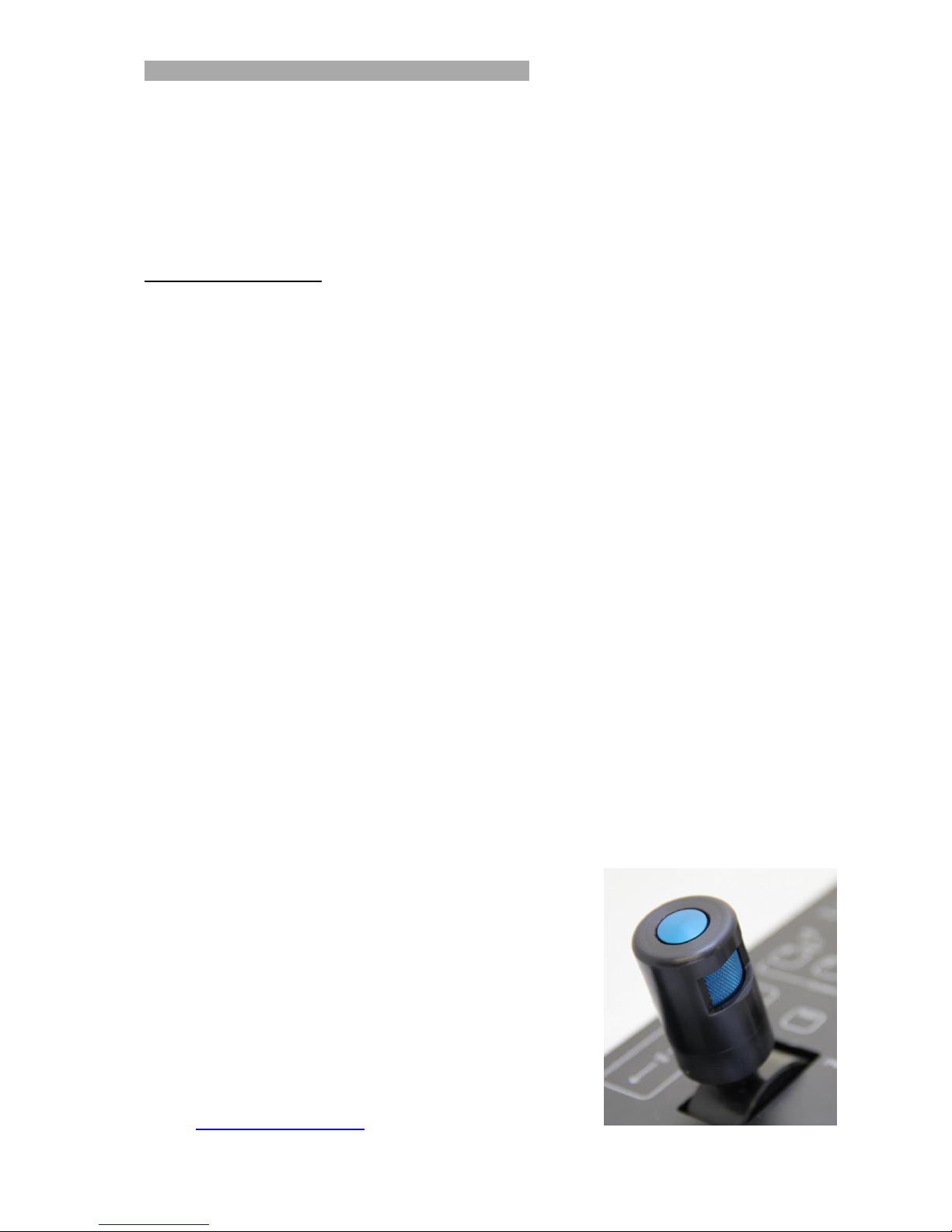
It is supplied with a standard ‘touch-down’ joystick. A continuous wheel iris knob with a
separate touch-down knob for master pedestal can be supplied to order.
The panel is designed to fit into a standard engineering desk with offset connectors
and fixing holes under the overlay which can be easily punctured to add the required
screws.
The unit employs our proprietary membrane panel technology with user adjustable
backlighting and individual illumination of all buttons and knobs.
BR Remote Ltd.
Units 14 - 20 Setley Ridge Vineyard
Lymington Road
Brockenhurst
Hampshire
SO42 7UF
UK
Tel: +44 1590 622440
Web: www.br-remote.com
Page 4
Page 4
Power & Data
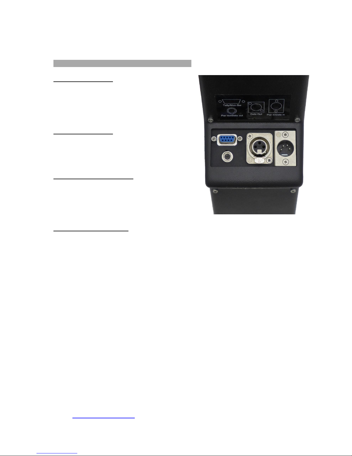
Power is supplied to the unit via the male XLR4 socket on the underside. 12 - 16 volts
DC. The unit generates RS485 data which is output on the XLR3 socket. The cable
length for the RS485 output can be up to 1km using good quality balanced cable for
the data pair.
Tally Inputs
Tally inputs are provided which can be triggered by contact closure (switch or relay)
or by connecting the appropriate pin to GND (pin 9) with an ‘open collector’ circuit.
The 9pin Dsub connects both the tally inputs and also the ‘touch down’ outputs.
Holding the appropriate tally pin to GND will generate a ‘Tally On’ command to the
camera. Removing the GND generates a ‘Tally Off’ command to the camera. A ‘tell tale’ red indicator will illuminate on the panel.
Monitor Switching
Also on this 9pin Dsub are open collector to GND outputs for monitor switching.
Operating the Touch Down switch will ground the pin associated with the selected
camera. Use pin 9 for GND connection.
A green indicator will illuminate on the panel when the touch-down is held.
Multiple Panels
Multiple panels can be cascaded using the Hirose 4pin connector. Both power and
data are distributed via this connector. Connect power to panel 1, then using a Hirose
to XLR cable connect to panels 2, 3, 4 etc. All the data finally appears on the output
of the last panel in the cascade.
Refer to page 8 for pin assignments.
Page 5
Page 5
Assignable Menus
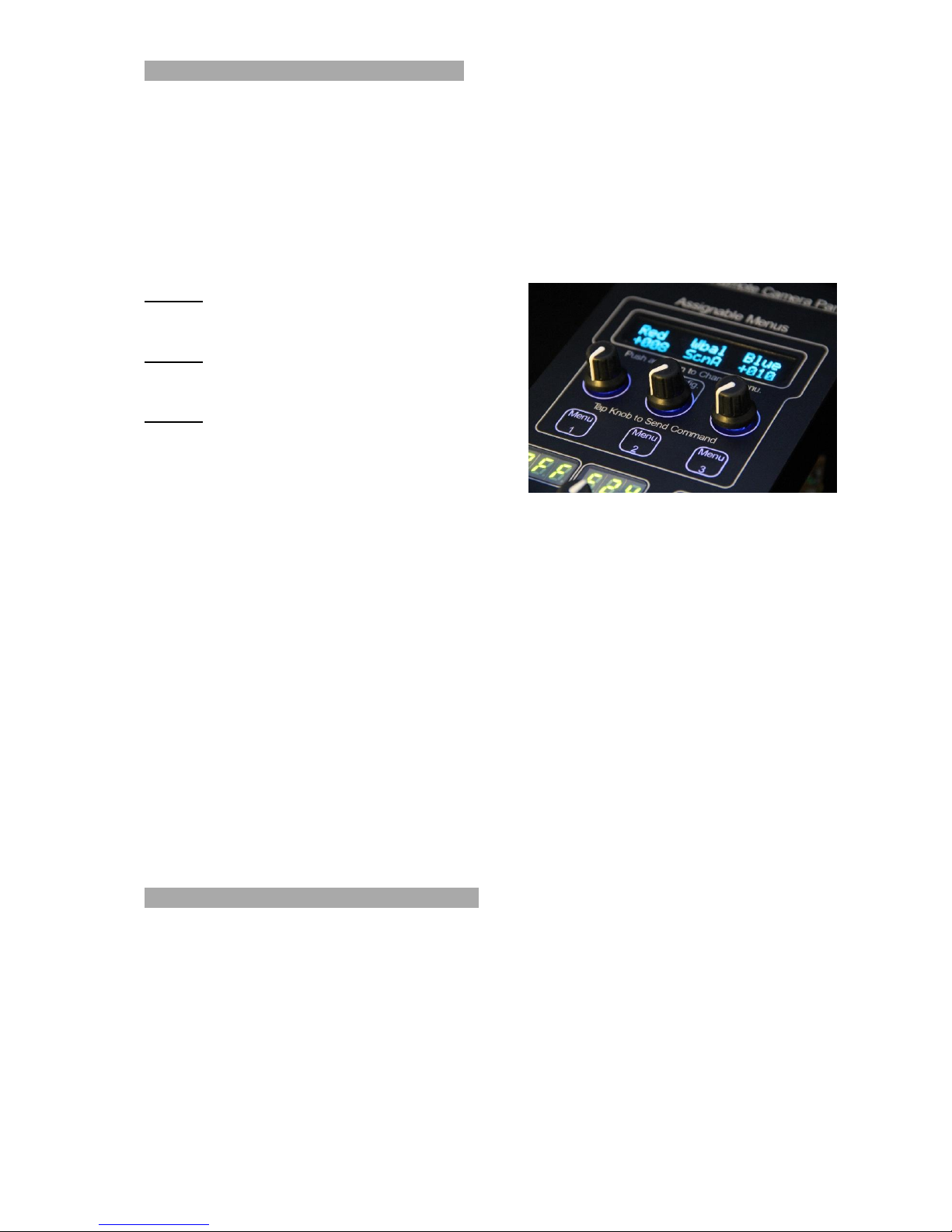
The unique feature of the panel is the Assignable Menus. There are 3 menus, each
with 3 adjustable parameters. The 3 menus are selected by simply pushing down the
appropriate menu button.
Any knob in any menu can be assigned to any available parameter enabling the
operator to customise the 3 menus. As supplied, some of the parameters are as
follows;
Menu 1
Red Gain, White Balance, Blue Gain
Menu 2
Red Pedestal, -----, Blue Pedestal
Menu 3
Detail, -----, Gamma
To assign a different parameter to a knob simply push down on the knob and rotate it
to change the function. When the knob is released the knob now controls the
parameter shown. If the function requires a switch action a brief touch down on the
knob toggles the switch action.
Numeric values are sent as the knob is rotated. Other values e.g. White Balance
Modes are only sent when the knob is pushed.
The panel sends unidirectional commands to the cameras but memorises all the sent
values for the 4 cameras selected and recalls these values when each camera is
selected. It also automatically stores these values whilst powered off and recalls all
values and the knob settings when powered up.
Because all the functions are software generated, additional functions can be added
as required and updates are simply a matter of replacing one, plug-in chip.
The display also shows the Master Pedestal level when adjusted.
Configuration
The centre assignable knob has additional configuration parameters. The additional
settings are;
Camera Model Sony, Ikegami, Panasonic, Hitachi, JVC, Bradley, etc.
Backlight Adjustment Level 1 - 10 for low light visibility
SDI/HDSDI format Some cameras support multiple formats
Tally Light setup Enables or inhibits tally light commands
Zoom Focus generator Allows temporary control of zoom & focus for line up
Change Head Nos. Changes the current ID No. to a different No.
Page 6
Page 6
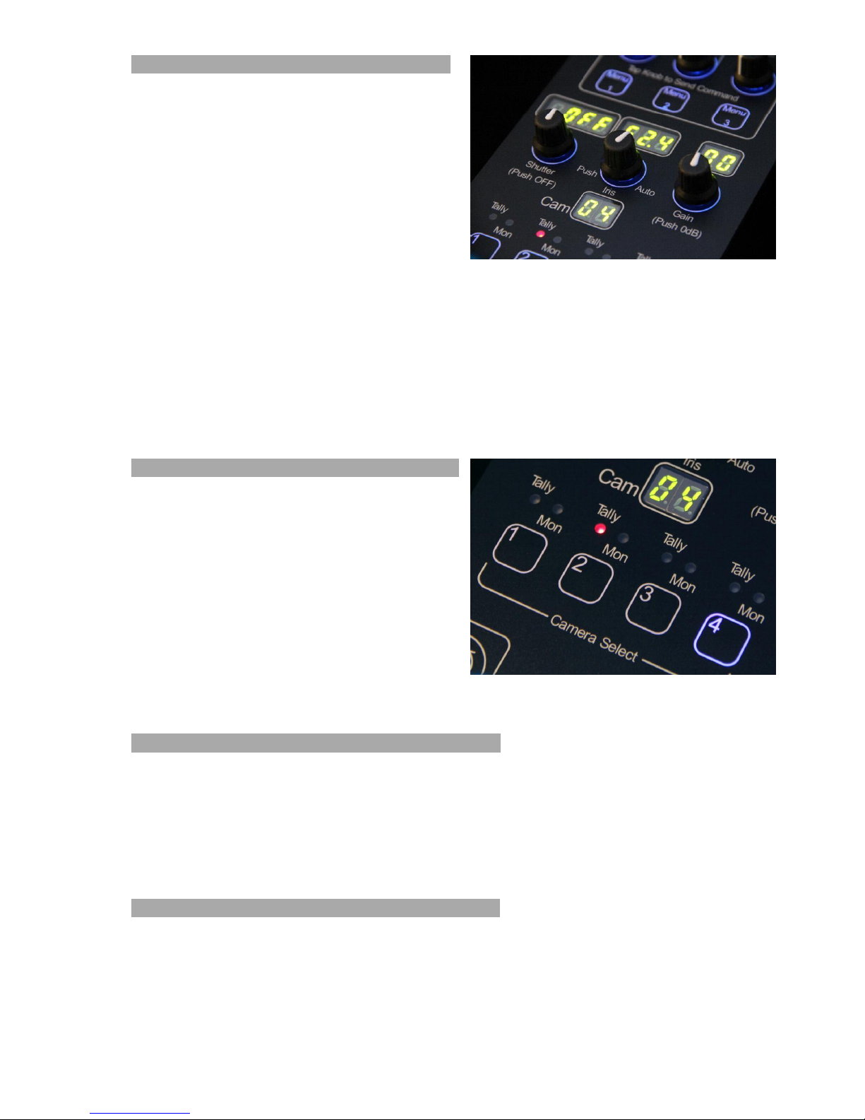
Shutter, Iris, Gain
Situated in the central section of the panel are
the controls and displays for Shutter, Iris, and
Master Gain.
Each of the knobs can be rotated or pushed
down. Rotation adjusts the value which is
then displayed by the LEDs.
Touch down on the ‘Shutter’ knob switches
the shutter OFF. (1/50 or 1/60 sec in most
cameras)
On the latest models, a brief touch down on the ‘Iris’ knob toggles control of the Iris
or ND Filter from the Iris Joystick. Iris can always be controlled with the centre knob.
Push and hold on the ‘Iris’ knob switches the camera to Auto Iris (if supported). The
Iris display will show if BARS are selected.
Touch down on the ‘Gain’ knob switches the gain to 0dB.
Camera Selection and Display
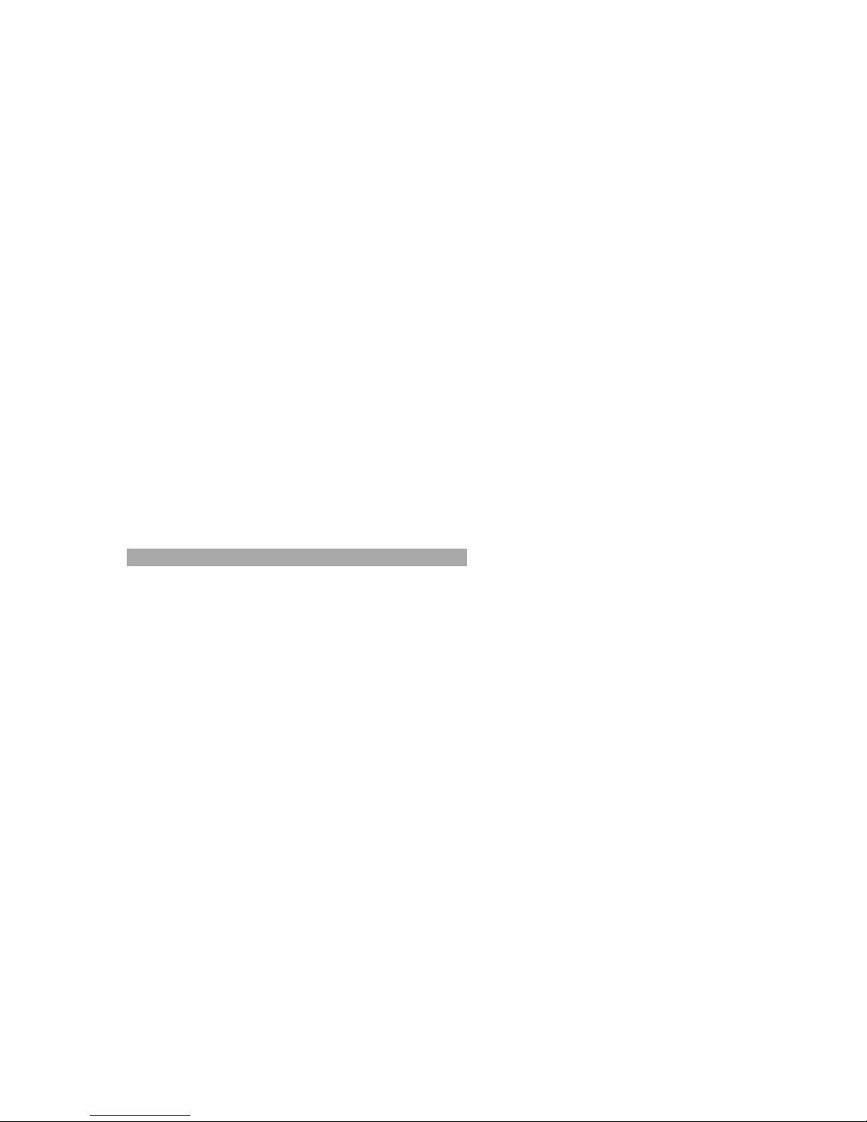
The ‘Camera Select’ buttons are used to
select one of 4 cameras. The selected
camera is displayed in the LED display. Any
4 sequential cameras in the range 1 - 99 can
be controlled by the panel.
Internal DIP switches select the first camera in
the range as a binary number. For example; if
switches 1 & 3 are ON this the binary
representation of 5. The panel will then
control cameras 5 - 8.
Tally Indicators & Monitor Switching LEDs
Above each camera select button are 2 indicators – Tally and Monitor. A RED
indicator shows when a tally input has been received. A ‘Tally On’ command is sent
to the camera when the tally is received. When the tally is removed a ‘Tally Off’
command is sent to the camera. A GREEN indicator shows if the joystick touch down
is operated.
Joystick Control
The joystick offers iris and pedestal control with ‘touch down’. When moved, the
appropriate value is displayed on the LED display. A friction adjustment is provided
underneath the panel.
This joystick can have several functions;
Page 7
Page 7
1. Normal manual Iris control
2. Micro Gain override when in Auto Iris. (In 0.1dB increments for smooth exposure
control).
3. ND Filter control (If the ND filter is fitted to the camera).
The ND Filter (if fitted) if selected by a brief touch down on the Iris knob. The ND filter
is continuously variable and can be used to control the exposure whilst keeping the
iris at a fixed value.
The sensitivity of the iris control is adjusted with the ‘Iris Gain’ knob. Holding this
knob down for 3 seconds locks the panel from accidental operation. The LED displays
will be blanked out and show ‘locked’ in the main OLED display. Hold down again for
3 seconds to unlock the panel.
The iris centre position is adjusted using the central ‘Iris’ knob.
Master Pedestal is adjusted by rotating the blue knob. The value is shown on the
OLED display at the top of the panel.
There is also a ‘Bars’ button immediately above the joystick. Press this for 2 seconds
to select colour bars ON. A short press selects colour bars OFF.
Currently Available Controls
Iris, Iris Range, Auto Iris
Master Pedestal, Gain, Shutter, Bars
Gamma, Aperture Correction (Detail)
Scene Files A, B, C, D.
White Balance - Scene, PUSH, Auto Tracing, 5600K, 3200K
Auto Black Balance
Red, Green and Blue Gain
Red, Green and Blue Pedestal
Output Standards (1080i/p/50,1080i/p/60, 720p/50, 720p/60, PAL 4:3/16:9, NTSC
4:3/16:9)
Filter Wheel, Camera Menu Access
Sync phase adjustments
Tally output to cameras
Remote Relay Switching
InfraRed On/Off
Iris Control Sensitivity, Panel Lock, ND Filter
Camera Model selection
Camera select (any 4 sequential cameras up to 99)
Backlight Intensity
Tally Inputs, Monitor select via GPIO
Zoom / Focus Generator
Change Head Numbers
Page 8
Page 8
Other functions can be adjusted via the camera menu displays. Additional functions,
not supported on the standard panel, can be included in the assignable function
menus by arrangement with BR Remote.
Connections & Pinouts
XLR4 - Power input
Pin 1 = GND
Pin 2 = Data A (RS485)
Pin 3 = Data B (RS485)
Pin 4 = +12v
XLR3 - Data Output
Pin 1 = GND
Pin 2 = Data A (RS485)
Pin 3 = Data B (RS485)
Hirose 4 - Cascade output
Pin 1 = GND
Pin 2 = Data A (RS485)
Pin 3 = Data B (RS485)
Pin 4 = +12v
9 pin Dsub - Tally inputs
Pin 1 = Cam 1 - Tally input (hold to GND for Tally ON)
Pin 2 = Cam 1 - Touch Down output. Open collector to GND**
Pin 3 = Cam 2 - Tally input (hold to GND for Tally ON)
Pin 4 = Cam 2 - Touch Down output. Open collector to GND**
Pin 5 = Cam 3 - Tally input (hold to GND for Tally ON)
Pin 6 = Cam 3 - Touch Down output. Open collector to GND**
Pin 7 = Cam 4 - Tally input (hold to GND for Tally ON)
Pin 8 = Cam 4 - Touch Down output. Open collector to GND**
Pin 9 = Common for Tally inputs (GND)
Contact closure or ‘Open Collector’ switching can be used for Tally.
Removing the GND from the tally inputs will trigger a ‘Tally OFF’ command to the
camera.
.BR Remote Ltd.
Units 14 - 20 Setley Ridge Vineyard
Lymington Road
Brockenhurst
Hampshire
SO42 7UF
UK
Tel: +44 1590 622440
Web: www.br-remote.com
 Loading...