

Page 1

Read this guide thoroughly.
It contains important safety information.
Minimum recommended operator’s age: 16 years old.
Keep this Operator’s Guide in the watercraft.
2015
OPERATOR’S
Includes Safety, Watercraft and
Maintenance Information
GUIDE
2015
SERIES
SERIES
SPARK
TM
2 1 9 0 0 1 3 9 5
SPARK
Original Instructions
Page 2
WARNING
Disregarding any of the safety precautions and instru ctions contained in
this Operator’s G uide,
SAFETY DVD
video and on-product safety labels
could cause injury including the possibility of death!
CALIFORNIA PR OPOSITION 65 WARNING
WARNING
This vehicle contains or emits chemicals known to the state of California to
cause cancer and birth defects or other reproductive harm.
In Canada, products are distributed by Bombardier Rec reational Products Inc.
(BRP).
In USA, products are distributed by BRP US Inc.
This is a non-exhaustive list of trademarks that are the property of Bombardier
Recreational Products Inc. or its affiliates:
ACE
TM
iTC
TM
Sea-Doo
®
iBR
TM
O.T.A.S.
TM
SPARK
TM
iControl
TM
Rotax
®
XPS
TM
smo2015-005 en JT
®™ and the BRP logo are trademarks of Bombardier Recreational Products Inc. or i ts affiliates.
©2014 Bombardi
er Recreational Products Inc. and BRP US Inc. All rights reserved.
Page 3

FOREWORD
Dieses Handbuch ist möglicherweise in Ihrer Landessprache
Deutsch
verfügbar. Bitte wenden Sie sich an Ihren Händler oder besuchen Sie:
www.operatorsguide.brp.com.
English
Español
Français
日本語
Nederlands
Norsk
Português
Suomi
Svenska
This guide may be available in your language. Check with your dealer or
go to: www.operatorsguide.brp.com.
Es posible que este manual esté disponible en su idioma. Consulte a su
distribuidor o visite: www.operatorsguide.brp.com.
Ce guide peu t être disponible dans votre lang ue. Vérifier avec votre
concessionnaire ou aller à: www.operatorsguide.brp.com.
このガイドは、言語によって翻訳版が用意されています。.
ディーラーに問い合わせるか、次のアドレスでご確認ください:
www.operatorsguide.brp.com.
Deze handleiding kan beschikbaar zijn in uw taal. Vraag het aan uw dealer
of ga naar: www.operatorsguide.brp.com.
Denne boken kan finne s tilgjengelig på ditt eget språk. Kontakt din
forhandler eller gå til: www.operatorsguide.brp.com.
Este manual pode estar disponível em seu idioma. Fale com sua
concessionária ou visite o site: www.operatorsguide.brp.com.
Käyttöohjekirja voi olla saatavissa omalla kielelläsi. Tarkista jälleenmyyjältä
tai käy osoitteessa: www.operatorsguide.brp.com.
Denna bok kan finnas tillgänglig på ditt språk. Kontakta din återförsäljare
eller gå till: www.operatorsguide.brp.com.
Congratulations on your purchase
of a new Sea-Doo
®
personal watercraft (PWC). It is backed by the BRP
warranty and a network of authorized
Sea-Doo personal watercraft dealers
ready to provide the parts, service or
accessories you may require.
Your dealer is committed to your satisfaction. He has taken training to perform the initial setup and inspection of
your watercraft as well as completed
the final adjustment before you took
possession. If you need more complete servicing information, please ask
your dealer.
At delivery, you were also informed of
the warranty coverage and signed the
PREDELIVERY CHECK LIST
to ensure
your new watercraft was prepared to
your entire satisfaction.
Know Before you Go
To learn how to reduce the risk for you
or other persons being inju red or killed,
read the following sections before you
operate the watercraft:
–
SAFETY INFORMATION
–
WATERCRAFT INFORMATION
Read and understand all safety labels
on your watercraft and watch attentively your
Failure to follow the warnings contained in this Operator's Guide can
result in serious injury or death.
BRP highly recommends that you take
a safe boating course. Please check
with your dealer or local authorities for
availability in your area.
In certain areas, an operator competency card is mandatory to operate a
pleasure craft.
SAFETY DVD
video.
.
_______________
1
Page 4
FOREWORD
WARNING
Get familiar with this PWC; it may
exceed the performance of other
PWCs you have ridden.
Safety Messages
This Operator’s Guide utilizes the following symbols and words to emphasize particular information:
The safety alert symbol
a potential injury hazard.
indicates
WARNING
Indicates a potential hazard which,
if not avoided, could result in serious injury or death.
CAUTION Indicates a poten-
tially hazardous situation which, if
not avoided, could result in minor or
moderate injury.
The information contained in this d ocument is correct at the time of publication. However, BRP maintains a policy of continuous improvement of its
products without imposing upon itself
any obligation to install them on products previously manufactured. Due
to late changes, some differences between the m a nu facture d product and
the descriptions and/or specifications
in this guide may occur. BRP reserves
the right at any time to discontinue or
change specifications, designs, features, models or equipment without
incurring any obligation upon itself.
This Operator's Guide and the
DVD
video should remain with the wa-
tercraft when it's sold.
SAFETY
NOTICE
which, if not followed, could severely damage watercraft components or other property.
Indicates an instruction
About this Operator's
Guide
This Operator's Guide has been prepared to acquaint the owner/operator
or passenger with this personal watercraft and its various controls, maintenance and safe riding instructions.
Keep this Operator's Guide in the watercraft as you can refer to it for operation, instructing others, maintenance
and troubleshooting.
Note that this guide is available in several languages. In the event of any discrepancy, the English version shall prevail.
Ifyouwanttoviewand/orprintan
extra copy of your Operator's Guide,
simply visit the following web s ite
www.operatorsguide.brp.com.
_______________
2
Page 5

TABLE OF CONTENTS
FOREWORD .......................................................................... 1
Know Before you Go............................................................. 1
Safety Messages................................................................. 2
About this Operator's Guide .................................................... 2
SAFETY INFORMATION
GENERAL PRECAUTIONS.......................................................... 8
Avoid Carbon Monoxide Poisoning ............................................. 8
Avoid Gasoline Fires and Other Hazards ....................................... 8
Avoid Burns from Hot Parts ..................................................... 8
Accessories and Modifications ................................................. 8
SPECIAL SAFETY MESSAGES .................................................... 9
Reminders Regarding Safe Operation.......................................... 9
Water Sports (Towing with the Watercraft) (3UP Models Only)............. 13
Hypothermia..................................................................... 14
Safe Boating Courses........................................................... 15
ACTIVE TECHNOLOGIES (iCONTROL).......................................... 16
Introduction...................................................................... 16
iTC (intelligent Throttle Control) ................................................ 16
iBR (intelligent Brake and Reverse System) (Models with iBR) ............. 17
SAFETY EQUIPMENT.............................................................. 18
Required Safety Equipment.................................................... 18
Additional Recommended Equipment ........................................ 20
PRACTICE EXERCISES............................................................. 21
Where to Practice Exercises ................................................... 21
Practice Exercises .............................................................. 21
Important Factors Not to Neglect.............................................. 22
NAVIGATION RULES............................................................... 23
Operating Rules ................................................................. 23
FUELING ............................................................................. 25
Fueling Procedure............................................................... 25
Fuel Requirements.............................................................. 26
TRAILERING INFORMATION ..................................................... 27
IMPORTANT ON-PRODUCT LABELS............................................ 28
Watercraft Safety Labels ....................................................... 28
Compliance Labels.............................................................. 32
PRE-RIDE INSPECTION ............................................................ 36
What to Do Before Launching the Watercraft ................................ 36
What to Do After Launching the Watercraft .................................. 39
_______________
3
Page 6

TABLE OF CONTENTS
WATERCRAFT INFORMATION
CONTROLS .......................................................................... 42
1) Handlebar ..................................................................... 43
2) Engine START/STOP Button................................................. 43
3) Engine Cut-Off Switch ....................................................... 43
4) Throttle Lever................................................................. 44
5) iBR Lever (intelligent Bra ke and Reverse) (M odels w ith iBR) ............. 44
6) Mode Button.................................................................. 45
MULTIFUNCTION GAUGE (LCD) ................................................. 46
Multifunction Gauge Description .............................................. 46
Navigating the Multifunction Display .......................................... 48
EQUIPMENT......................................................................... 49
1) Glove Box ..................................................................... 50
2) Safety Equipment Kit Storage Compartment .............................. 50
3) Storage Bin (Convenience Package)........................................ 50
4) Seat............................................................................ 51
5) Passenger Handholds........................................................ 52
6) Boarding Step (Convenience Package) ..................................... 52
7) Boarding Platform ............................................................ 53
8) Front and Rear Eyelet ........................................................ 53
9) Bilge Drain Plug............................................................... 54
10) Sponsons.................................................................... 54
BREAK-IN PERIOD.................................................................. 55
Operation During Break-In Period.............................................. 55
OPERATING INSTRUCTIONS..................................................... 56
Boarding the Watercraft ........................................................ 56
How to Start Engine............................................................. 60
How to Stop the Engine ........................................................ 60
How to Steer the Watercraft ................................................... 61
How to Engage Neutral (Models with iBR).................................... 62
How to Engage Forward (Models with iBR)................................... 62
How to Engage and Use Reverse (Models with iBR)......................... 62
How to Engage and Use Braking (Models with iBR) ......................... 63
General Operating Recommendations........................................ 65
OPERATING MODES (ROTAX ACE 900 HO) .................................... 67
Touring Mode.................................................................... 67
Sport Mode ...................................................................... 67
SPECIAL PROCEDURES ........................................................... 70
Jet Pump Water Intake and Impeller Cleaning................................ 70
Capsized Watercraft ............................................................ 71
Submerged Watercraft ......................................................... 72
Water-Flooded Engine.......................................................... 72
Towing the Watercraft in Water................................................ 72
_______________
4
Page 7

TABLE OF CONTENTS
MAINTENANCE INFORMATION
MAINTENANCE SCHEDULE...................................................... 76
MAINTENANCE PROCEDURES .................................................. 80
Engine Oil........................................................................ 80
Engine Coolant .................................................................. 81
Steering Alignment ............................................................. 83
Central Body..................................................................... 83
Battery ........................................................................... 87
Ignition Coils..................................................................... 90
Spark Plugs ...................................................................... 91
Exhaust System ................................................................. 91
Heat Exchanger and Water Intake Grate ...................................... 92
Sacrificial Anode................................................................. 93
Fuses............................................................................. 93
WATERCRAFT CARE ............................................................... 95
Post-Operation Care ............................................................ 95
Watercraft Cleaning............................................................. 95
STORAGE AND PRESEASON PREPARATION.................................. 96
Storage........................................................................... 96
Preseason Preparation ......................................................... 98
TECHNICAL INFORMATION
WATERCRAFT IDENTIFICATION ............................................... 100
Hull Identification Number ................................................... 100
Engine Identification Number................................................ 100
ENGINE EMISSIONS INFORMATION.......................................... 101
Manufacturer's Responsibility ............................................... 101
Dealer's Responsibility ....................................................... 101
Owner Responsibility ......................................................... 101
EPA Emission Regulations ................................................... 101
SPECIFICATIONS ................................................................. 102
TROUBLESHOOTING
TROUBLESHOOTING GUIDELINES ........................................... 106
MONITORING SYSTEM ......................................................... 111
Fault Indicators and Message Display Information......................... 111
Beeper Code Information .................................................... 113
_______________
5
Page 8

TABLE OF CONTENTS
WARRANTY
BRP LIMITED WARRANTY – USA ANDCANADA:2015SEA -DOO
®
PERSONAL
WATERCRAFT .................................................................... 116
US EPA EMISSION-RELATED WARRANTY ................................... 120
CALIFORNIA AND NEW YORK EMISSION CONTROL WARRANTY
STATEMENT FOR MODEL YEAR 2015 SEA-DOO
®
PERSONAL
WATERCRAFT..................................................................... 123
BRP INTERNATIONAL LIMITED WARRANTY: 2015 SEA-DOO
®
PERSONAL
WATERCRAFT..................................................................... 127
BRP LIMITED WARRANTY FOR THE EUROPEAN ECONOMIC AREA,
THE COMMONWEALTH OF THE INDEPENDENT STATES, TURKEY: 2015
SEA-DOO
®
PERSONAL WATERCRAFT........................................ 132
CUSTOMER INFORMATION
PRIVACY INFORMATION........................................................ 138
CHANGE OF ADDRESS/OWNERSHIP......................................... 139
_______________
6
Page 9

SAFETY
INFORMATION
________
SAFETY INF
ORMATION
________
7
Page 10

GENERAL PRECAUTIONS
Avoid Carbon Monoxide
Poisoning
All engine exhaust contains carbon
monoxide, a deadly gas. Breathing carbon monoxide can cause headaches,
dizziness, drow siness, nausea, confusion and eventually death.
Carbon monoxide is a colorless, odorless, tasteless gas that may be present
even if you do not see or smell any engine exhaust. Deadly levels of carbon
monoxide can collect rapidly, and you
can quickly be overcome and unable
to save yourself. Also, deadly levels of
carbon monoxide can linger for hours
or days in enclosed or poorly ventilated
areas. If you experience any symptoms of carbon monoxide poisoning,
leave the area immediately, g et fresh
air and seek medical treatment.
To prevent serious injury or death from
carbon monoxide:
– Never run the watercraft in poorly
ventilated or partially enclosed areas s uc h as watercraft houses, seawalls or other boats in close proximity. Ev en if you try to ventilate
engine exhaust, carbon monoxide
can r ap idly reach dangerous levels.
– Never run the watercraft outdoors
where engine exhaustcan be drawn
into a building through openings
such as windows and doors.
– Never stand behin d the watercraft
while the engine is running. A person standing behind a running engine may inhale high concentrations
of exhaust fumes. Inhalation of concentrated exhaust fumes that contain carbon monoxide can result in
CO poisoning, serious health problems and death.
flame many feet away from the engine. To reduce the risk of fire or explosion, follow these instructions:
– Use only an approved red gasoline
container to store fuel.
– Strictly adhe r e to the instructions in
FUELING
– Never start watercraft if gasoline or
gasoline vapor odors is present in
theenginecompartment.
– Never start or o perate th e engine if
the fuel cap is not properly secured.
– Do not carry gasoline containers in
the storage bin (if equipped) or anywhereelseonthewatercraft.
Gasoline is poisonous and can cause
injury or death.
– Never siphon gasoline w ith your
mouth.
– If you sw allo w gasoline, get any in
your eyes, or inhale gasoline vapors,
see a doctor immediately.
If gasoline is spilled on you, wash
thoroughly with soap and water and
change your clothes.
section.
Avoid Burns fro m Hot Parts
Certain components may become hot
during operation. Avoid contact during and shortly after operation to avoid
burns.
Accessories and
Modifications
Do not make unauthorized modifications, or use accessories that are not
approved by BRP. Since these changes
have not b ee n tested by BRP, they
may increase the risk of accidents or
injuries, and they can make the w atercraft illegal for use on wate r.
Avoid Gasoline Fires and
Other Hazards
Gasoline is extremely flammable and
highly explosive. Fuel vapors can
spread and be ignited by a spark or
________
8
SAFETY IN
See your authorized Sea-Doo dealer
for available accessories for your watercraft.
FORMATION
________
Page 11

SPECIAL SAFETY MESSAGES
Reminders Regarding Safe
Operation
The performance of this watercraft
may significantly exceed that of other
watercraft you may have operated.
Make sure you read and understand
the content of this Operator's Guide
to become completely familiar with
the controls and operation of the watercraft before embarking on your first
trip, or taking on a passenger(s). If you
have not had the opportunity to do so,
practice driving solo in a suitable traffic free a rea to bec ome accusto med
to the feel and response of each control. Be fully familiar with all controls
before accelerating above idle speed.
Do not assume that all PWCs handle
identically. Each model differs, often
substantially.
Always keep in mind that as the throttle lever is returned to the idle position,
less directional control is available. To
turn the wa tercraft, both steering and
throttle are necessary. Do not release
throttle when tr ying to steer away from
objects. Your need throttle to steer. If
the engine is shut off, directional control is lost.
Although most watercraft have no
means of braking, advancement in
technologies now permit us to offer
some models that are equipped with
a braking system called the iBR
tem. Practice braking maneuvers in
a safe traffic-free area to be c ome familiar with handling under braking and
with stopping distances under various
operating conditions.
TM
sys-
WARNING
Stopping distance will vary d
pending on initial speed, load,
wind, number of riders and water
conditions. The amount
power commanded by the operator using the iBR lever (intelligent
Brake and Reverse) wi
stopping distance.
of braking
ll also affect
e-
When braking, riders must brace themselves against the deceleration force
to prevent from moving forward on the
watercraft and losing bala nce.
When o perating an iBR equipped watercraft, be aware that other boats following or operating in close proximity
may not be able to stop as quickly.
When at speed and the brake is first
applied, a plume of w ater will shoot up
in the a ir behind t he watercraft which
may cause the operator of a following
watercraft to momentarily loos e sight
of your PWC. It is important to inform
the operator of a watercraft who intends to follow in a convoy formation,
of the braking and m aneuvering capability of your PWC, what the plum e of
water indicates, and that a greater distance should be maintained between
watercraft.
When actuating the iBR control lever
while the watercraft has some forward speed, the braking mode will
engage and generate a deceleration
proportional to the iBR lever position.
The more you pull in the iBR lever, the
greater the braking force becomes.
Be careful to gradually actuate the iBR
lever to adjust the intensity o f the braking force, and to simultaneously release the throttle lever.
The brake feature of the iBR system
cannot prevent your PWC from drifting due to current or wind. It has no
braking effect on the rearward motion.
Also note that your engine must be
runningtobeabletousethebrake.
The personal watercraft jet thrust can
cause injur y. The jet pump m ay pick up
debris and throw it rearward causing a
risk of injuring people, damaging the jet
pump, or other property.
Observe the instructions on all safety
labels. They are there to help assure
that you have a safe and enjoyable outing.
________
SAFETY INF
ORMATION
________
9
Page 12

SPECIAL SAFETY MESSAG ES
Do not store any objects in areas that
are not designed specifically for storage.
Riding with passenger(s), pulling
tubes, a skier, or a wake boarder makes
the PWC handle differently and requires greater skill.
All PWC models come equipped with
tow eyelets that can be used for mooring and as tie-down points when trailering, can be used to attach a tow rope
for a skier, tube or wake boarder. Do
not use these attachment points or any
other portion of the watercraft to tow
a para-sail or any other craft. Personal
injury or severe damage may occur.
Combustion engines need air to operate; consequently this PWC cannot
be totally watertight. Any maneuvers
such as turning constantly in tight circles, plunging the bow through waves,
or capsizing the watercraft, that cause
the air in let openings t o be under water may cause severe engine problems
due to water ingestion. Refer to
ERATING INSTRUCTIONS
and the
in this Operator's Guide.
Engine exhaust contains carbon
monoxide (CO), which can cause serious health problems or death if inhaled
in sufficient quantities. Do not operate
the PWC in a confined area or allow
CO to accumulate around the PWC,
or in enclosed or sheltered areas such
as when docked, or when rafting. Be
aware of the risk of CO emanations
from exhaust of other PWCs.
Know the waters in which the watercraft is to be operated. Current, t
rapids, hidden obstacles, wakes and
waves etc. can affect safe operation.
It is not advisable to operate th
tercraft in rough waters or inclement
weather.
In shallow water, proceed with caution
and at very low speeds. Grounding or
abrupt stops may result in
WARRANTY
section contained
subsection
injury and
OP-
ides,
ewa-
watercraft damage. Debris may also
be picked up and thrown rearward by
the jet pump onto people or property.
Keep the tether cord attached to the
operator's PFD or wrist (wrist strap
required) at all times and keep it free
from snagging on the handlebars to
help ensure the engine stops should
the operator fall off. After riding, remove the tether cord from the engine
cut-off switch to avoid unauthorized
use by children or others. If the operator falls off the watercraft and the
tether cord is not attached as recommended, the watercraft engine will not
stop.
Ride within your limits and lev el of riding ability.
Always ride responsibly and safely.
Use common sense and courtesy.
Respect the environment and the
rights of other users of the waterways.
As the operator and owner of a PWC,
you are responsible for damage by the
wake of your PWC. Do not let anyone
throw refuse overboard.
While your watercraft has the capacity of operating at high speeds, it
is strongly recommended that high
speed operation only be applied when
ideal conditions exist and are permitted. Higher speed operation requires a
higher degree of skill and increases the
risk of severe injuries.
The forces generated on the body of
riders while turning, negotiating waves
or wakes, operating in choppy waters,
or falling off the watercraft, especially
at higher speeds, may cause injury in
cluding the possibility of broken bones
or more serious bodily injuries. Remain flexible and avoid sharp turn
PWCs are not designed for night-time
operation.
Avoid riding in very rough waters or
practicing extreme maneuvers
jumping wakes or waves .
s.
like
-
10
_______
SAFETY I
NFORMATION
________
Page 13

SPECIAL SAFETY MESSAGES
Before Getting Underway
For safety reasons and proper care, always perform the pre-ride inspection
as specified in your Operator's Guide
before operating your watercraft.
Do not exceed the payload or pas senger capacities for your watercraft.
Overloading can affect maneuverability, stability and performance. Also ,
heavy seas reduce capacity. A payload
or person capacity plate is not an excuse for failure to use common sense
or good judgment.
Regularly inspect the PWC, hull, engine, safety equipment, and all other
boating gear and keep them in safe operating condition.
Be sure you have the minimum required safety equipment, PFDs and
any additional gear needed for your
cruise.
Operator and Passenger Awareness
Read and understand all safety labels
on the Sea-Doo PWC, the Operator's
Guide, all other safety documents, and
watch the
operating the PWC.
Respect applicable laws. Check local
and federal boating laws applicable
to the waterways where you intend
to use your watercraft. Learn the local navigation rules. Know and understand the applicable navigation system
(suchasbuoysandsigns).
Remember that sun, wind, fatigue or
illness may impair your judgement and
reaction time.
Operation of this PWC by a person under 16 years of age, or a person with a
disability that imp airs vision, reaction
time, judgment, or operation of the
controls is NOT recommended.
SAFETY DVD
video before
Ensure that all lifesaving equipment,
including fire ex tinguisher (not suppliedwithvehicle),areinsafeoperating condition and easily accessible.
Show all passengers where this equipment is stored on the PWC, and make
sure they know how to use it.
Keep an eye on the weather. Check local weather broadcasts before departure. Be alert to changing conditions.
Keep accurate and up-to-date charts of
the boating area on board. Before getting underway, check water conditions
in the planned boating area.
Ensure there is enough fuel on board
for the planned trip. Always verify fuel
level before use and during the ride.
Apply the principle of 1/3 of the fuel
to reach your destination, 1/3 to return, and keep 1/3 in reserve. Allow
for changes due to adverse weather or
other delays.
Always properly use the tether cord
when operating the watercraft and ensure that all passengers are familiar
with its use.
Ensure that any operator and all passengers know how to swim and how
to reboard the PW C from the water.
Boarding in deep water can be strenuous. Practice in chest-deep water
before operating or embarking your
watercraft in deep water. Ensure that
any operator and all passengers wear a
PFD at all times and take extra precautions when boating.
Never turn handlebar while someone
is near the rear of watercraft. Keep
away from steering moving parts (nozzle, iBR gate, linkages, etc.).
Do not start the engine or operate the
watercraft if anyone is in the water
nearby, or near the rear of the watercraft
________
SAFETY INF
Be aware of the iBR gate movement
when starting the engine, shutti
down the engine or using the iBR lever.
Automatic movement of the gate may
squeeze fingers or toes of peop
ing a hold on the back or your PWC.
ORMATION
________
ng
le tak-
11
Page 14

SPECIAL SAFETY MESSAG ES
The operator and passenger(s) should
be properly seated and have a firm grip
on a handhold before starting the watercraft, and at all times when the watercraft is in motion. All passenger(s)
shouldbeinstructedtousethehandholds provided, or to hold on to the
waist of the person in front of them.
Eachpassengermustbeabletosimultaneously place both feet firmly flat
against each footwell when properly
seated. When going over waves, or in
rough water, passenger(s) may raise
their b od y slightly off the se at to absorb the shocks with their legs.
When braking or decelerating, riders
must brace themselves against the deceleration force to prevent from moving forward on the watercraft and losing balance.
WhenacceleratingonaPWCwithpassenger(s), whether from a complete
stop or while underway, always do so
progressively. Fast acceleration may
cause your passenger(s) to lose their
balance and fall rearward off the watercraft. Make sure that your passenger(s) are aware o f or can anticipate
any rapid acceleration.
Severe internal injuries can occur if
water is forced into body cavities as a
result of falling into w ater or being near
a jet thrust nozzle. Consequently, the
wearingofawetsuitbottomishighly
recommended.
Keep away from the intake grate while
the engine is running. Items such
as long hair, loose clothing, or PF
straps can become entangled in moving parts.
D
Before reboarding, make sure engine
is off and the tether cord is remove d
from the engine cut-off switch.
To prevent accidental starting, always
remove the tether c ord from the engine cut-off switch when swimmers
are boarding, nearby, or during removal
of any weeds or debris from the intake
grate.
On a PWC, nev er place your feet and
legs in the water to aid turning.
Operation by Minors
Minors should always be supervised
by an adult whenever operating a watercraft. Laws regarding the minimum
age and licensing requirements of minors may vary from one jurisdiction to
another. Be sure to contact the local
boating authorities for information regarding the legal operation of a PWC in
the intended jurisdiction of use. BRP
recommends a minimum operator age
of 16 years old.
Drugs and Alcohol
Never use with drugs or alcohol. Like
driving a car, driving a watercraft requires the operator to be sober, attentive and alert. Operating a watercraft
while intoxicated or under the influence of drugs is not only dangerous,
but it is also a Federal offense carrying a significant penalty. These laws
are vigorously enforced. The use of
drugs and alcohol, singly or in combination, decreases reaction time, impedes judgment, impairs vision, and
inhibits your ability to safely operate a
watercraft.
If the throttle lever is depressed while
braking, the iBR system will disable the
throttle command by the user. Wh
releasing the iBR lever while the throttle lever is still depressed, the throttle command will regain co
generate an acceleration after a short
delay. Release throttle lever if acceleration is not needed.
12
_______
en
ntrol and
SAFETY I
WARNING
Alcohol consumption and boatingdonotmix! Operatingwith
the use of drugs or alcohol endangers the lives of your passengers,
other boaters, and yourself. Federal laws prohibit operating a watercraft with the use of drugs or
alcohol.
NFORMATION
________
Page 15

SPECIAL SAFETY MESSAGES
Water Sports (Towing
with the Watercraft) (3UP
Models Only)
WARNING
Avoid personal injury! Your PWC
is not designed for and should not
be used for pulling another craft,
parasails, kites, gliders, or any device which can become airborne.
Use your watercraft only for water
sports it was designed for.
Water skiing, wakeboarding, or riding
a towed inflatable apparatus are some
of the more popular water sports. Taking part in any water sport requires
increased safety awareness by the participant and the watercraft operator. If
you have never towed someone behind your PWC before, it is a good idea
to spend some hours as an observer,
working with and learning from an experienced operator. It is also important
to be aware of the skill and experience
of the person being towed.
Everyone participating in a water sport
should observe these guidelines:
– Riding with passenger(s) or pulling
a tube, skier or wakeboarder makes
the watercraft handle differently
and requires greater skill.
– Always respect the safety and com-
fort of your passenger(s) and person
being tow ed on skis, wa keboard or
other water products.
– Always carry an observer when
pulling a tube, skier or wakeboarder
to observe the person being towed
and inform the operator about the
participants' hand signals. The operator must focus his attention on
operating the watercraft and the
waters ahead.
– Proceed with only as much speedas
required and follow the observers'
instructions.
– When pulling a tube, skier, or a wake
boarder, do not make tight sharp
turns or use the braking system
unless absolutely necessary. Remember that although this PWC
is manoeuvrable and has stopping
capabilities (models w ith iBR), the
person in tow may not be able to
avoid an obstacle, or the PWC with
which it is being towed.
– Allow only capable swimmers to
take part in any water sport.
– Always wear an approved personal
flotation device (PFD). Wearing
a properly designed PFD helps a
stunned or unconscious person stay
afloat.
– Be considerate to others you share
the water with.
– Both the operator and observer
shouldmonitorthelocationofthe
tow rope when participating in watersports. A slack tow rope can become entangled with a person(s) or
objects on the PWC or in the water, particularly when making a tight
turn or c ircling, and cause serious
personal injury.
– Do not tow a person in an y water
sport on a short tow rope such that
the person inhales exhaust fumes
in concentration. Inhalation of co
centrated exhaust fumes, which
contain carbon monoxide, can result in CO poisoning, personal in
and death.
– Use a tow rope of sufficient length
andsize,andmakesureitisadequately secured to your wa
Always store tow rope when not in
use. While some watercraft are
equipped or can be fitt
specially designed towing mechanism, avoid installing a tow pole
on a PWC. It can becom
should someone fall on it.
– Give immediate attention to a per-
son who has fallen. He or she is
vulnerable in t
may not be seen by other boaters.
he water alone and
tercraft.
ed with a
eahazard
n-
jury
________
SAFETY INF
ORMATION
________
13
Page 16
SPECIAL SAFETY MESSAG ES
– Approachapersoninthewaterfrom
the lee side (opposite the direction
of the wind). Turn off the motor before coming close to the person.
– Participate in water sports only
in safe areas. Stay away from
other boats, channels, beaches,
restricted areas, swimmers, and
heavily traveled waterways and underwater obstructions.
– Turn off the engine and anchor the
watercraft before swimming.
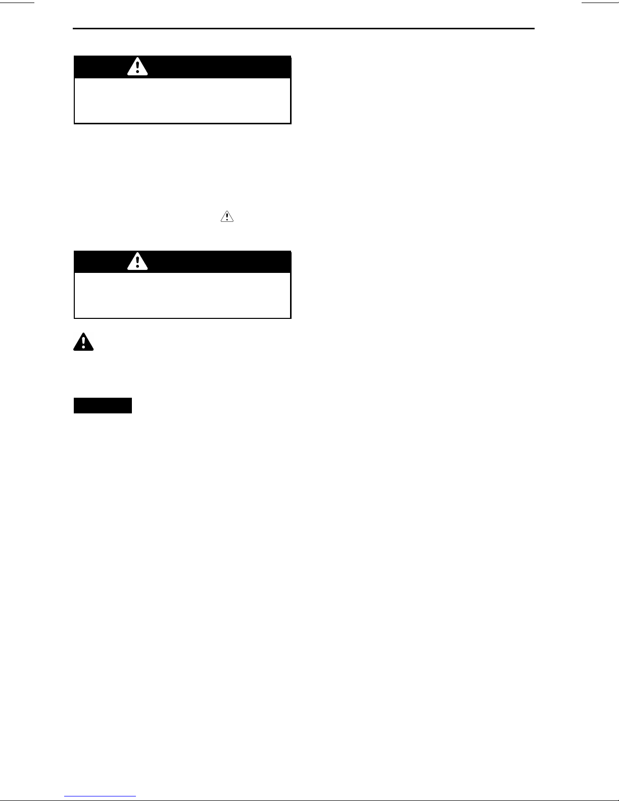
– Swim only in areas design ated as
safe for swimming. These are usually marked with a swim area buoy.
Do not swim alone or at night.
F00A2LY
straps can become entangled in moving parts resulting in serious injury or
drowning. In shallow water, shells,
sand, pebbles or other objects could
be drawn up by the jet pump and be
thrown rearward.
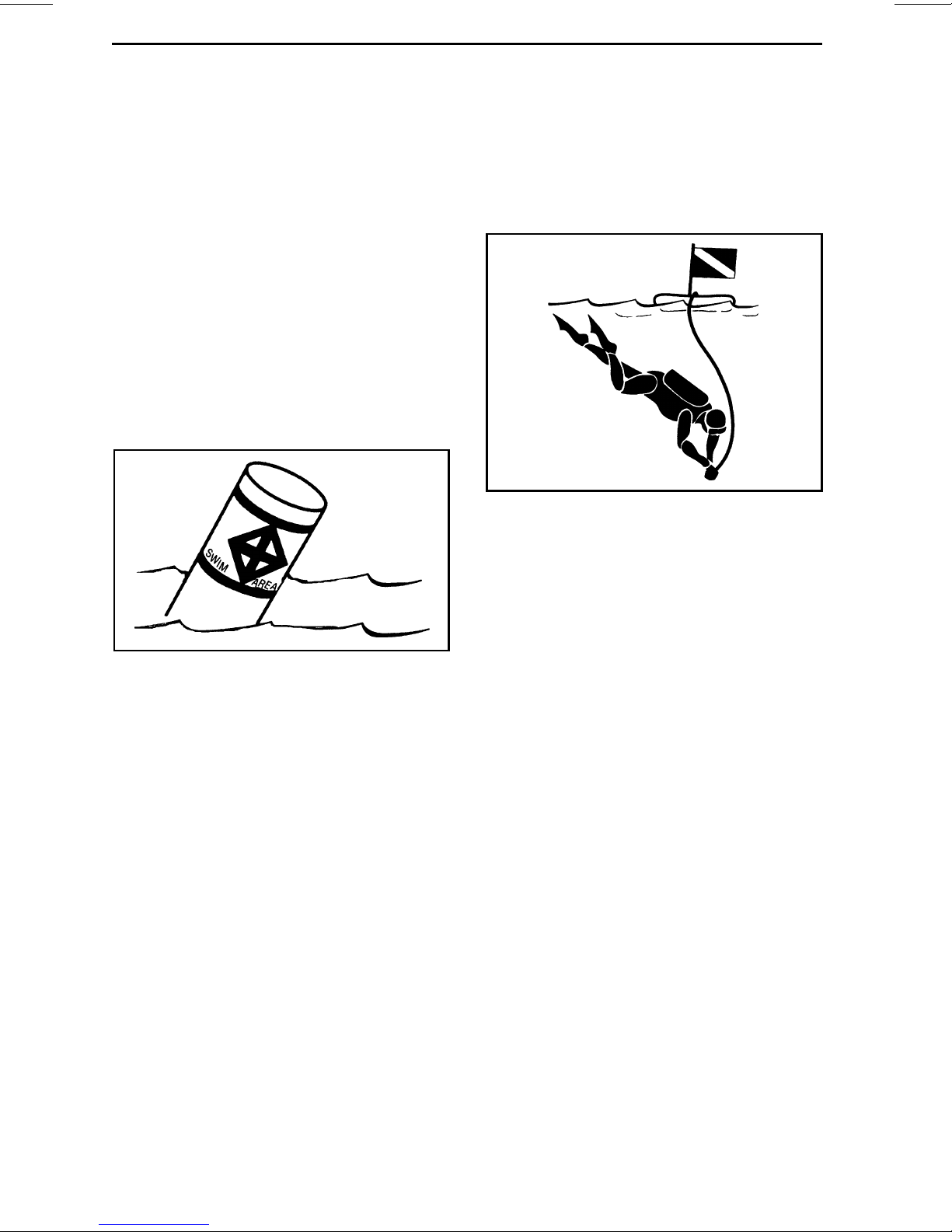
F00A2MY
DIVER DOWN FLOAT
For more information on approved, legal and safe practice of water sports,
please contact the local legal authority
on water sports safety for the area you
plan to practice in.
SWIM AREA BUOY
– Do not water ski between sunset
andsunrise. Itisillegalinmostareas.
– Do not drive the watercraft directly
behind a water skier, tuber or wakeboarder. At 40 km/h (25 MPH) per
hour, the watercraft will overtake a
person who falls in the water 60 m
(197 ft) in front of your waterc
about 5 seconds.
– Shut off the engine and remove the
tether cord from the engine cut-off
switch when anyone is in the
nearby.
– Stay at least 45 m (148 ft) away
from areas marked by a diver down
float.
Avoid personal injury! Do not allow
anyone near the propu
intake grate, even when the engine
is off. Items such as long hair, loose
clothing or person
lsion sy stem or
al flotation device
raft in
water
Hypothermia
Hypothermia, the loss of body heat
resulting in a subnormal body temperature, is a significant cause of death in
boating accidents. After an individual
has succu m bed to hypothermia, he or
she will lose consciousness and then
drown.
PFDs can increase survival time because of the insulation they provide.
Naturally, the warmer the water, the
less insulation one w ill require. When
operating in cold water (below 4°C
(40°F)) consideration should be gi
to using a coat or jacket style PFD as
they cover more body area than the
vest style PFDs.
ven
14
_______
SAFETY I
NFORMATION
________
Page 17

Some points to remember about hypothermia protection:
– While afloat in the water, do not at-
tempt to swim unless it is to reach
a nearby watercraft, fellow survivor, or a floating object onto which
you can lean or climb. Unnecessary swimming increases the rate
of body heat loss. In cold water,
drown-proof methods that require
putting your head in the water are
not recommended. Keep your head
out of the water. This will greatly
lessen heat loss and increase your
survival time.
– Maintain a positive attitude about
your survival and rescue. This will
improve your chances of extending
your survival time until you can be
rescued. Your will to live does make
a difference!
– If there is more than one person
in the water, huddling together is
recommended. This action tends to
reduce the rate of heat loss and thus
increase the survival time.
– Always wear your PFD. It won't help
you fight off the effects of hypothermia if you don't have it on when you
go into the water.
SPECIAL SAFETY MESSAGES
Safe Boating Courses
Many countries recommend or require
a boating safety course. Check with
your local competent authorities.
Check local and federal boating laws
applicable to the waterways where
you intend to use your watercraft.
Learn the local navigation rul
and understand the applicable navigation system (such as buoys and signs).
________
es. Know
SAFETY INF
ORMATION
________
15
Page 18

ACTIVE TECHNOLOGIES (iCONTROL)
Introduction
NOTE: Some functions or features described in this section may not apply to
every PWC model, or may be available
as an option.
iControl
tems) provides an environment
whereby the operator can control
many systems without taking his
hands off the handlebars.
All controls are at the operator's finger
tips and activated by pressing a button
or pulling a lever. The operator's a tten tion can thus remain focused on the
water and driving the watercraft.
Each control is electronic and provides
a command signal to an electronic
module whose function is to assure
proper operation of its system within
set parameters.
The various systems grouped under
iControl are the:
–iTC
– iBR (intelligent Brake and Reverse)
– O.T.A.S. (Off Throttle Assisted
These systems function together to
provide features such as braking, improved watercraft response to o perator inputs, increased m aneu ve rab ility
and control.
It is extremely important for operators
to read all information contained in this
Operator's Guide so as to become familiar with this watercraft, its systems,
controls, capabilities an d limitations.
TM
(intelligent Control sys-
TM
(intelligent Throttle Control)
(if equipped)
Steering).
iTC (intelligent Throttle
Control)
The system uses an electronic throttle
control (ETC) that provides command
signals to the ECM (Engine Control
Module). With this system, there is no
need for a traditional throttle cable.
The iTC allows the following operating
modes:
– Touring mode
– Sport mode
– O.T.A.S.
Touring M ode (Rotax ACE 900 HO)
In to uring mode, available engine
power and acceleration is reduced
when accelerating from a complete
stop and when operating in the low
engine power range under certain conditions.
When throttle is applied, the e ngine
will progressively accelerate throug h
its operating range whereby full power
eventually becomes available. If the
engine is throttled down sufficiently
and for a long enough period of time,
engine power and acceleration will
again be reduced.
Sport Mode (Rotax ACE 900 HO)
In sport mode, maximum engine
power is available throughout the engine operational range.
Refer to
subsection for detailed instructions.
O.T.A.S.
(Off-Throttle Assisted Steering)
The O.T.A.S.
Steering) is also controlled by the iT C.
The O.T.A.S. (Off-Throttle Assisted
Steering) system provides additional
maneuverability in off-throttle situations.
The OTAS system is electronically activated w hen the operator initia tes a
full turn and releases the throttle at the
same time.
Limitations
The O.T.A.S. system cannot help you
maintain control or prevent collisions
in all situations.
TM
.
MULTIFUNCTION GAUGE
TM
System
TM
(Off Throttle Assisted
16
_______
SAFETY I
Refer to
subsection for details.
NFORMATION
OPERATING INSTRUCTION S
________
Page 19

ACTIVE TECHNOLOGIES (iCONTROL)
iBR (intelligent Brake and
Reverse System) (Models
with iBR)
This watercraft uses an electronically
controlled braking and reverse system
called the iBR system (intelligent Brake
and Reverse).
The iBR module controls the position
of the iBR gate to provide:
– Forward
– Reverse
–Neutral
–Braking.
The operator commands the position
of the iBR gate using either the throttle
lever for forward position, or the iBR
lever for neutral, reverse, and for the
braking function.
NOTE: The iBR lever can only be used
to command a change in the gate position if the engine is running.
It cannot prevent your watercraft from
drifting in current or wind.
Using the iBR system significantly reduces the stopping distance of this
watercraft and can increase its maneuverability as it can be used in a straight
line, in a turn, at high or low speeds, or
to propel the wa te rc ra ft in reverse for
docking or maneuvering in very close
quarters.
Under ideal conditions, experienced
operators were consistently able to
reducethestoppingdistanceofawatercraft equipped with an iBR system
by ap prox imately 3 3%, from an initial
speed of 80 km/h (50 MPH).
Limitations
Even when equipped with an iBR system, watercraft d o not have th e ability
of land based vehicles.
Stopping distance will vary notably depending on initial speed, load, wind,
current, water conditions and the
amount of braking.
The iBR system has no effect on the
rearward motion.
________
SAFETY INF
ORMATION
________
17
Page 20
SAFETY EQUIPMENT
Required Safety
Equipment
The operator and the passenger(s)
must wear an approved Personal Flotation Device (PDF) that is suitable for
PWC use.
Operator and passenger(s) should
have ready access to shatterproof
glasses should riding conditions or
personal preference warrant.
Wind, water spray and speed may
cause a person's eyes to water and
create blurred vision.
As the owner of the watercraft, you
are responsible for assuring that all
required safety equipment is aboard.
You should also consider supplying additional equipment as needed for your
safety and that of your passengers.
Check state and local regulations about
required safety equipment.
Safety equipment required b y regulations is mandatory. If local regulations
require additional equipment, it must
be approved by a competen t authority.
Minimum requirements include the
following:
– Personal flotation devices (PFDs)
– A buoyant heaving line of 15 m
(50 ft) minimum
– A watertight flashlight or approved
flares
– Signaling device
– Sound producing devices (airhorn or
whistle).
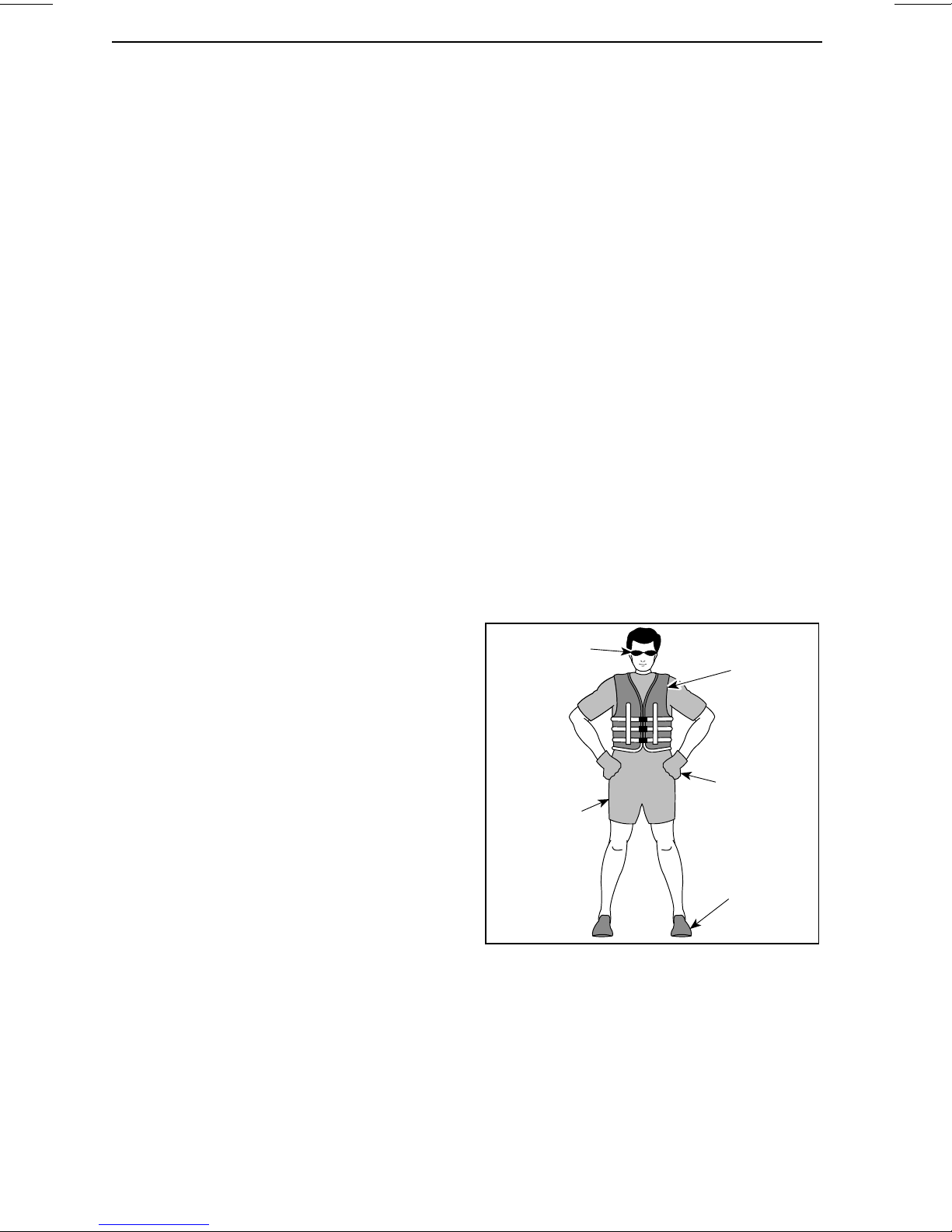
Recommended Protective G ear
The operator and passenger(s) of
PWCs must wear protective gear, including:
– A wet suit bottom, or thick tightly
woven and snug fitting clothing that
provides equivalent protection. As
an example, thin bike shorts would
not be appropriate. Severe internal injuries can occur if water is
forced into body cavities as a result of falling in the water or being near jet thrust nozzle. Normal
swimwear does not adequately protect against forceful entry of water
into the lower male or female body
opening(s).
– Footwear, gloves, safety goggles
or glasses are also recommended.
Some type of lightweight, flexible
foot protection is recommended.
This will help reduce possible injury,
should you step on sharp underwater objects.
Eye
protection
Wet suit
or wet suit
bottom
Vest-type
personal
flotation
device
Gloves
Foot
protection
18
_______
SAFETY I
F00A12A
NFORMATION
________
Page 21
SAFETY EQUIPMENT
Personal Flotation Devices (PFDs)
Each person on a recreational watercraft must wear a personal flotation
device (PFD) at all times. Ensure that
these PFDs meet your country's regulations.
A PFD provides buoyancy to help keep
the head and face above the water, and
to help maintain a satisfactory body position while in the water. Body weight
and age should be considered when
selecting a PFD. The buoyancy provided by the PFD should support your
weight in water. The size of the PFD
should be appropriate for the wearer.
Body weight and chest size are common methods used to size PFDs. It is
your responsibility to ensure that you
have the proper number and types of
PFDs on board to comply with federal
and local regulations, and that your
passengers know where they are and
how to use them.
PFD Types
There are five types of approved PFDs.
PFD Type I, Wearable, has the greatest
required buoyancy. Its design allows
for turning most unconscious persons
in the water from face down positionto
a vertical or slightly backward, face-up
position. It can greatly increase the
chances of survival. Type I is most
effective for all waters, especially offshore when rescue m ay be delayed. It
is also the most effective in rough waters.
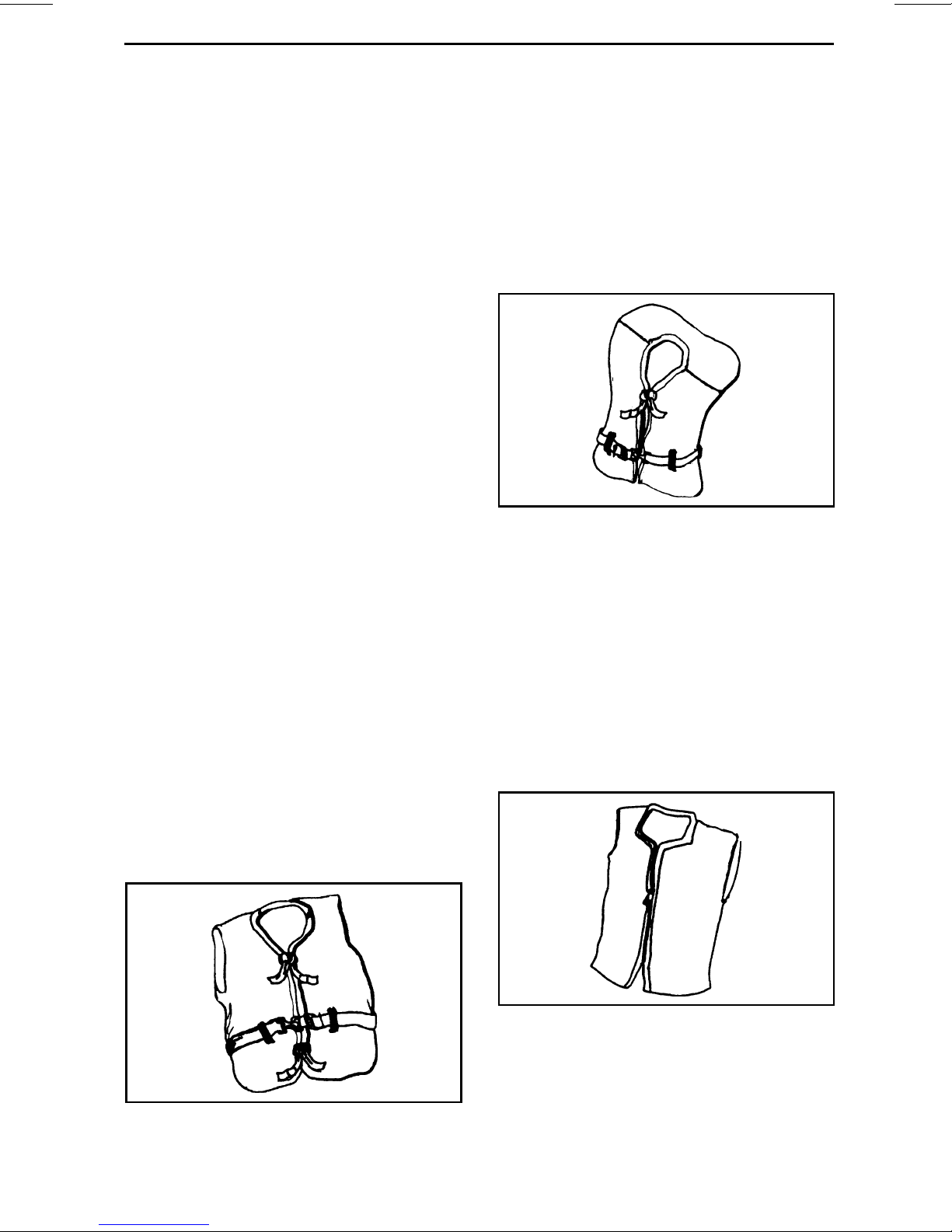
PFD Type II, Wearable, turns its
wearer in the same way as Type I, but
not as effectively. The Type Il does not
turn as many persons under the same
conditions as a Type I. You may prefer
to use this PFD where there is a probability of quick rescue such as in areas
where other people are commonly involved in wa ter activities.
F00A2DY
TYPE II — WEARABLE
PFD Type III, Wearable, allows wearers to place themselves in a vertical
or slightly backward position. It does
not turn the wearer. It maintains the
wearer in a vertical or slightly backward position and has no tendency
to turn the wearer face down. It has
the same buoyancy as a Type Il PFD
and may be appropriate in areas where
other people are commonly involved in
water activities.
F00A2CY
TYPE I — WEARABLE
________
SAFETY INF
F00A2EY
TYPE III — WEARABLE
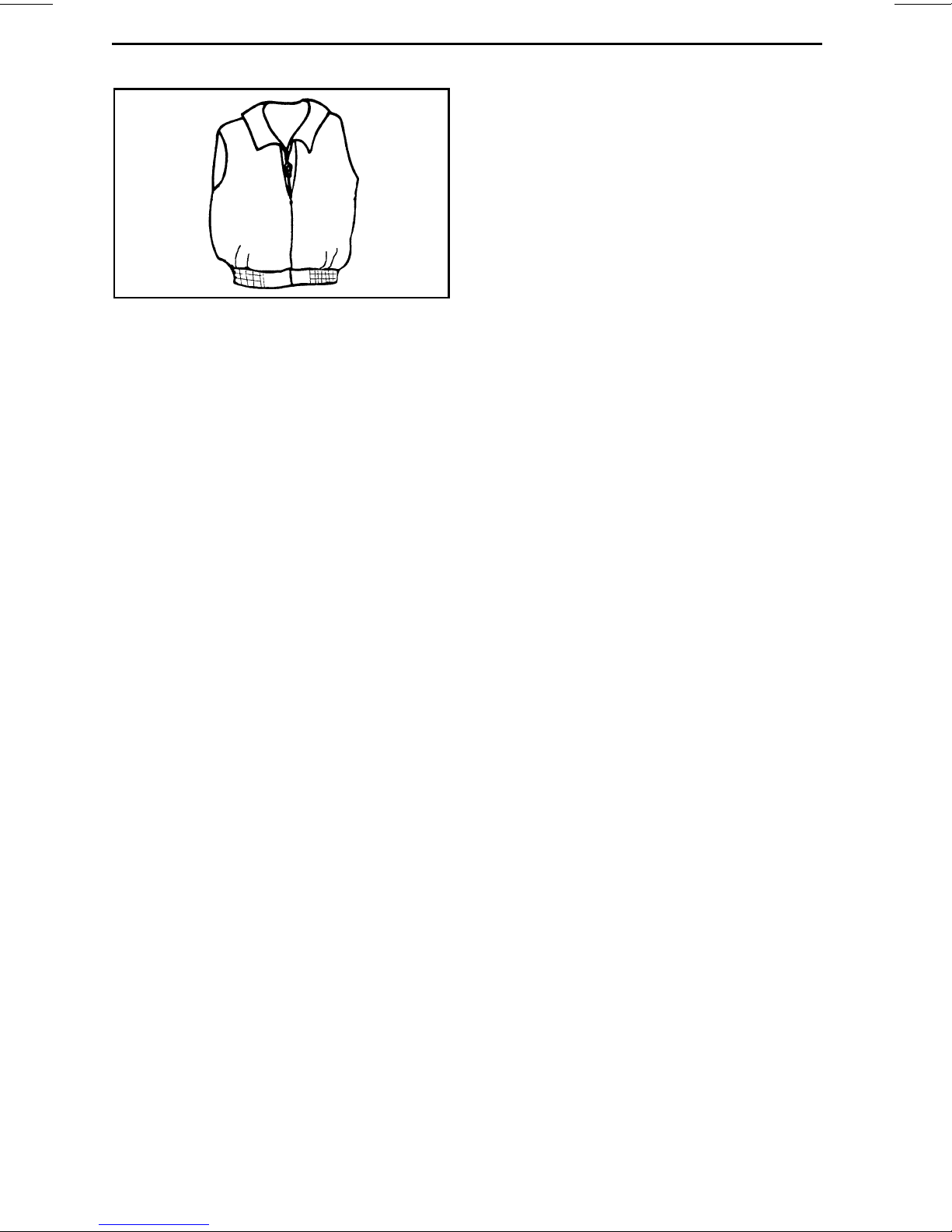
PFD Type V, Wearable, must be worn.
When inflated, it provides buoyancy
equivalent to Type I, I
When it is deflated, however, it may
not support some people.
ORMATION
________
lorIIIPFDs.
19
Page 22
SAFETY EQUIPMENT
Weighing the Risks vs Benefits
In order to decide whether or not you
should wear a helmet, it is best to consider the particular environment you
will be riding in, as well as other factors such as personal experience. Will
therebealotoftrafficonthewater?
What is your riding style?
F00A2GY
TYPE V — WEARABLE
Helmets
Some Important Considerations
Helmets are designed to offer some
degree of protection in case of impacts to the head. In most motorized
sports, the benefits of wearing a helmet clearly outweigh the drawbacks.
However, in the case of motorized watersports such as riding personal watercraft, this is not necessarily true as
there are some particular risks associated with the water.
Benefits
A helmet helps to reduce the risk of
injury in case of a head impact against
a hard surface such as another craft in
the case of a collision. Similarly, a helmet with a chin gu ard might help prevent injuries to the fac e, jaw or teeth.
Risks
On the other hand, in some situations
when falling off the waterc ra ft, helmets have a tendency to catch the
water, like a “bucket”, and put severe
stresses on the neck or spine. This
could result in choking, severe or permanent neck or spine injury or death.
The Bottom Line
Since ea ch option minimizes so me
risks, but increases others, before
each ride you must decide whether
to wear or not wear a helmet based on
your particular situation.
If you decide to wear a helmet, you
must then decide what type is the
most appropriate for the circumstances. Look for helmets that meet
DOT or Snell standards, and if possible, choose one designed for motorized watersports.
Additional Recommended
Equipment
It is recommended that you acquire
additional equipment for safe, enjoyable cruisin g . This list, which is not all
inclusive, includes items you should
consider acquiring.
– Local map
– First aid kit
– Tow rope
–Flares
– Mooring cords.
A cellular telephone in a waterproof
bag or container has also been found
to be beneficial to boaters when in distress or just for contacting someone
on shore.
Helmets may also interfere with peripheral vision and hearing, or increase
fatigue whic h, could contribute to increase the r isk of a c ollision.
20
_______
SAFETY I
NFORMATION
________
Page 23

PRACTICE EXERCISES
It is always a good idea to practic e and
get familiar with all controls, fun ction s
and handling characteristics of your
watercraft before venturing on the water.
Always secur e the tether cord to the
engine cut-off switch and the clip to
yourPFDorawriststrap.
Where to Practice
Exercises
Find a suitable area to practice the exercises. Ensure the area meet the following requirements:
– No traffic
– No obstacles
– No swimmers
– No current
– Ample space to maneuver
– Water depth is adequate.
Watercraft Equipped with iBR
Practice stopping the watercraft in
a straight line at various speeds and
braking force.
Remember that watercraft speed,
load, water conditions, current and
wind also affect stopping distances.
Reverse (Watercraft Equipped with
iBR)
Practice reverse operation to learn
how the watercraft operates in reverse
andreactswithsteeringinputs.
NOTE: Always perform this exe rcise
at slow speeds.
Avoiding an Obstacle
Practice obstacle avoidance (choose a
virtual point on the water) by steering
the watercraft and maintaining throttle.
Practice Exercises
Practice alone the following exercises.
Tur nin g
Practice turning in circles in both directions at slow speed. When comfortable with the exercise, increase
difficulty by making some figure 8.
When this is m astered, repeat the
above exercises but at increased
speed.
Stopping Distances
Watercraft not Equipped with iBR
Practice stopping the watercraft in a
straight line at different speeds.
Remember, water drag is the main
factor which reduces the watercraft
speed and thus the stopping distance.
NOTE: The watercraft speed, load,
current and wind also play an important
role in affecting stopping d istances.
Repeat exercise, but this time release
throttle while turning.
NOTE: With this exercise, you will
learn that you need throttle to steer the
watercraft in a different direction.
Docking
Watercraft not Equipped with iBR
NOTE: You can use the start and stop
button to reduce the docking speed.
Practice docking using the throttle and
steering to become familiar with the
response of the P WC and to develop
good control skills.
Watercraft Equipped with iBR
Practice docking using the throttle, iBR
lever and the steering to become familiar with the response of the PWC, an d
to d ev elop good control s kills.
NOTE: Remember that steering direction is reversed when backing.
________
SAFETY INF
ORMATION
________
21
Page 24

PRACTICE EXERCISES
Important Factors Not to
Neglect
In addition, always remember that the
following conditions have a d ire ct impact on how your watercraft will behave and respond to different inputs:
– Loads
– Currents
–Wind
– Water conditions.
Make sure to be alert to these conditions, and adapt accordingly. If possible, practice further in these conditions.
For delicate maneuvers, the best advice is always to try to reduce y our
speed to a minim um.
22
_______
SAFETY I
NFORMATION
________
Page 25
NAVIGATION RULES
Operating Rules
Operating a watercraft ca n be compared with driving on unmarked highways and roads. To prevent c ollis ions
or avoid other boaters, a system of operating rules must be followed. It’s not
only common sense... it’s the law!
Generally keep to your right and safely
avoid collision s by keeping a safe distance from other water craft, boats,
people and objects.
The follow in g illustration identifies different parts of a boat that are used
as directional reference points, the
bow being the front of the boat. The
port side o f boat (left side ) is visually
identifiable by a RED light off the bow,
and the starboard side (right side) by a
GREEN light.
smo2012-003-200
TYPICAL
Like a street traffic light, if you see a
RED light, STOP, give the right of way.
The other boat is to your right and it has
the right of way.
If you see a GREEN light, pass with
caution. The other boat is to your left,
you have the right of way.
Meeting Head-On
Keep right.
Bow
Port
1
F00A13Y
TYPICAL - DIRECTIONAL REFERENCE
POINTS
1. RED light
2. GREEN light (yield zone)
Stern
Starboard
2
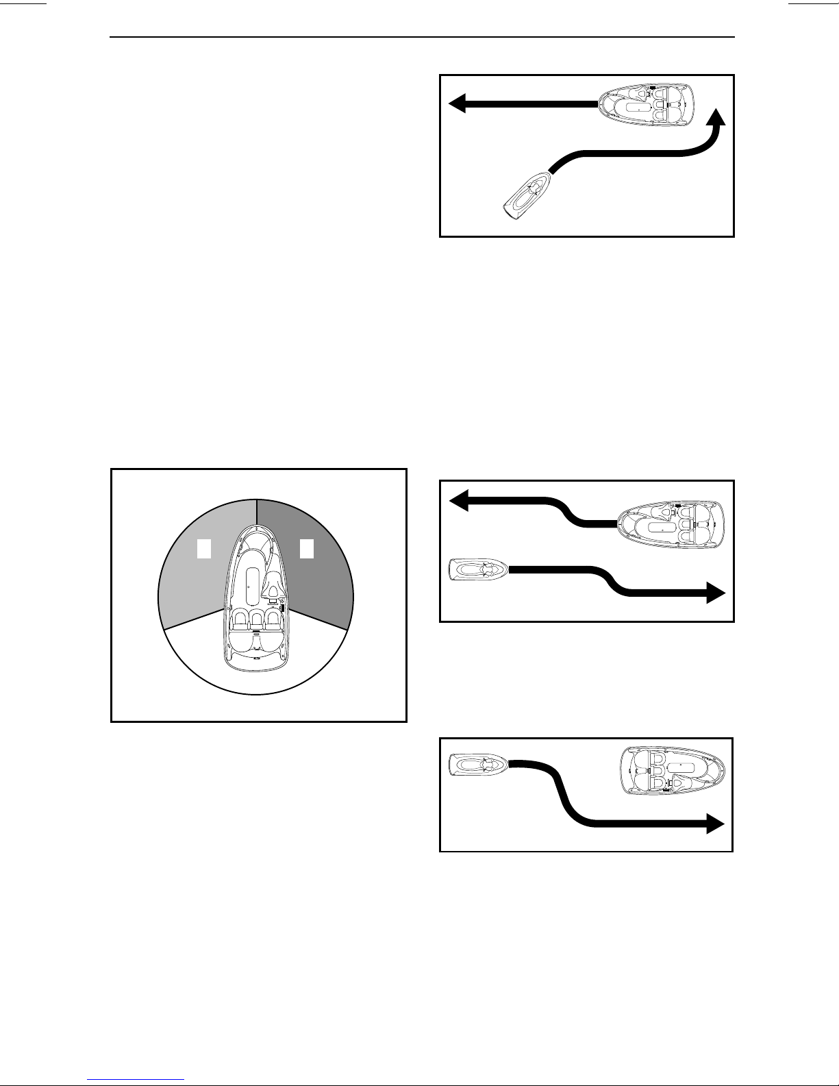
Crossing
Give the righ t of way to a watercraft
ahead and to your right. Never cross
in front of a boat, you should see his
RED light, he should see your GREEN
light (he has the right of way).
Personal watercraft (PWC) do not have
these colored lights, but the rule still
applies.
smo2012-003-201
TYPICAL
Passing
Give the right of way to other crafts and
keep clear.
smo2012-003-202
TYPICAL
Navigation System
Navigational aids, such as signs or
buoys, can assist y ou in identifying safe waters. Buoys will indicate
whether you should keep to the right
(starboard) or to the left (port) of the
________
SAFETY INF
ORMATION
________
23
Page 26

NAVIGATION RULES
buoy, or to which channel you can continue. They may also indicate whether
you are entering a restricted or controlledareasuchasanowakeorlow
speed zone. They may also indicate
hazards or pertinent boating information. Markers may be located on shore
or on the water. They can also indicate speed limits, no power c raft or
boating, anchorage and other useful
information. (The shape of each type
of marker will provide assistance).
Make sure you know and understand
the navigation system applicable to
the waterways where you intend to
use the watercraft.
Collision Avoidance
Do not release the throttle when trying to steer away from an obstacle.
Engine power and jet pump thrust is
required to steer the watercraft.
Always keep a constant lookout for
other water users, other boats or objects, especially when turning. Be alert
for conditions that may limit your visibility or block your visio n of others.
Respect the rights of other recreationists and/or bystanders and always
keep a safe distance from all other
watercraft, boats, people and objects.
Models with iBR
Unlike most other watercraft, this
PWC has a braking sy stem (iBR).
When o perating an iBR equipped watercraft, be aware that other boats following or operating in close proximity
may not be able to stop as quickly.
When at speed and the brake is first applied, a plume of water will shoot up in
the a ir behind the watercraft indicating
a braking manoeuvre.
It is important to inform the operator of
a watercraft who intends to follow in
a convoy formation of the braking and
maneuvering capability of your PWC,
what the plume of water indicates, and
that a greater distance should be maintained between both of you.
Stopping distance will vary depending
on initial speed, load, wind and water
conditions.
Although the pr eferable maneuver to
avoid an obstacle istosteer away while
applying throttle, the iBR can also be
used by fully braking and turning in the
appropriate direction to avoid the obstacle.
Do not wake or wave jump, ride the
surf line or attempt to spray or splash
others with your watercraft. You may
misjudge the ability of the watercraft
or your own riding skills and strike a
boat, watercraft or person.
This watercraft has the capability o f
turning more sharply than other boats,
however, unless in an emergency, do
not negotiate sharp, high speed turns.
Such m aneuvers make it hard for others to avoid you or understand where
you are going. Also, you and/or your
passenger(s) could be thrown f
watercraft.
24
_______
rom the
SAFETY I
NFORMATION
________
Page 27
FUELING
Fueling Procedure
WARNING
Fuel is flammable and explosive
under certain conditions. Always
work in a well ventilated area. Do
not smoke or allow open flames or
sparks in the vicinity.
1. Turn off engine.
WARNING
Always stop the engine before refueling.
2. Do not allow anyone to remain on
the watercraft.
3. Tie watercraft securely to the fueling pier.
4. Have a fire extinguisher (not supplied with vehicle) close at hand.
5. Remove the seat. Refer to
EQUIPMENT
6. Locate fuel tank cap.
section.
SEAT
in
WARNING
To prevent fuel back-flow, fill tank
slowly so the air can escape from
the fuel tank.
9. Stop filling immediately after the release of the gas pump nozzle handle
and wait a moment before removing the spout. Do not retract the gas
pump nozzle to put more fuel in fuel
tank.
WARNING
Do not overfill or top off the fuel
tank and l eave the watercraft in the
sun. As temperature increases,
fuel expands and may overflow.
10. Reinstall fuel tank c ap and tighten
it clockwise until you hear a ratchet
sound.
WARNING
Always wipe off any fuel spillage
from the watercraft.
smo2014-005-004_a
1. Fuel tank cap
7. Slowly unscrew the fuel cap counterclockwise.
WARNING
Fuel tank may be pressu
vapors may be released while removing the fuel tank cap.
8. Insert the gas pump spout into the
filler neck and f
ill up the fuel tank.
rized, fuel
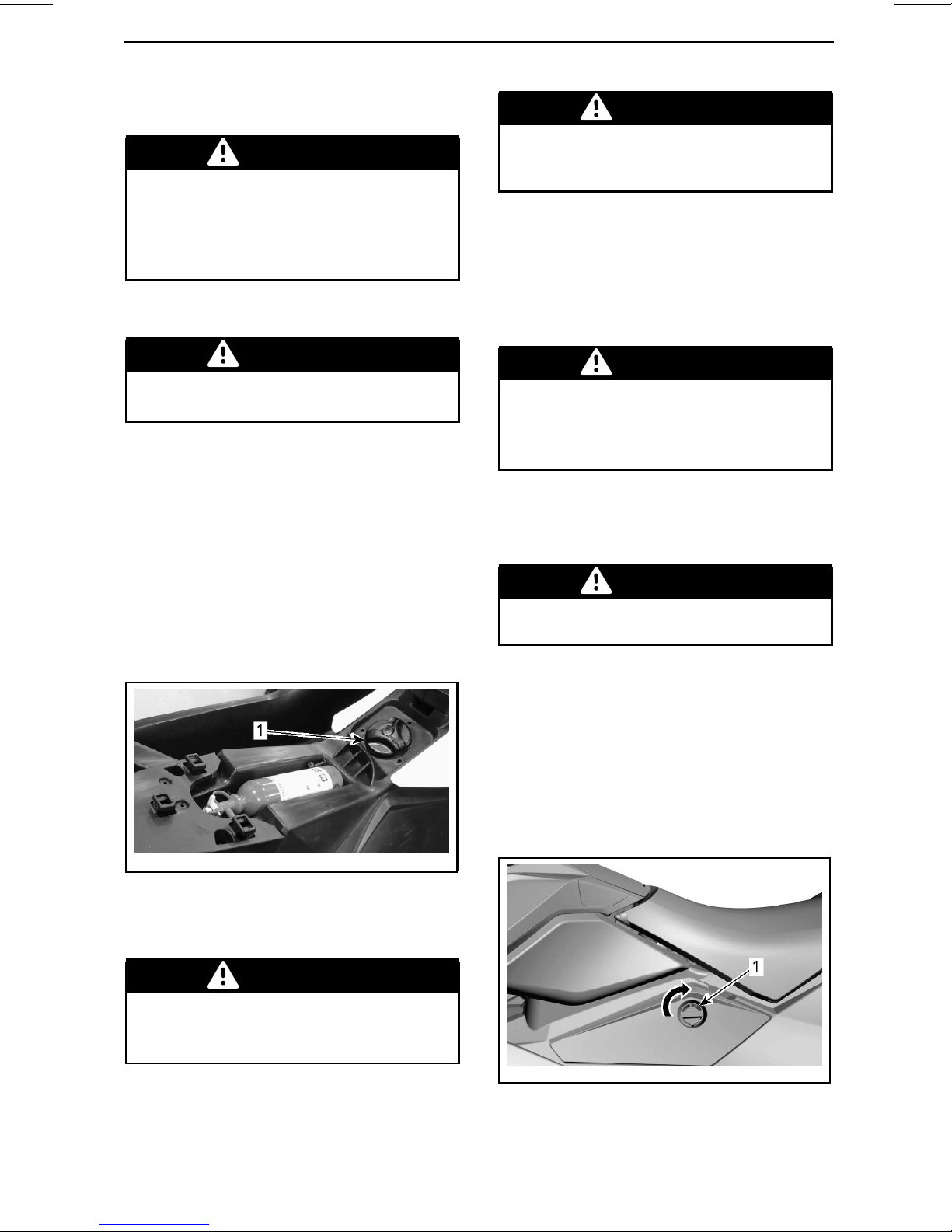
11. After refueling, always ensure
thereisnogasolinevaporodor
inside the engine compartment.
12. To access the engine compartment, turn the LH access cover
knob 1/4 turn clockwise, then pull
out to unsnap the rear portion and
slide rearward to remove.
smo2015-005-005_a
LH A CCESS COVER
1. To unlock, turn the knob 1/4 turn clockwise
________
SAFETY INF
ORMATION
________
25
Page 28

FUELING
WARNING
Do not start watercraft if gasoline
or gasoline vapor odor is present.
13. Reinstall the LH access cover in
reverse of removal procedure and
lock the knob by turning it 1/4 turn
counterclockwise.
smo2015-005-005_b
LH A CCESS COVER
1. To lock, turn the knob 1/4 turn
counterclockwise
14. To reinstall the seat, refer to
in
EQUIPMENT
section.
Fuel Requirements
SEAT
Alcohol fuel blending varies by country and region. Your vehicle has been
designed to operate using t he recommended fuels, however, be aware of
the following:
– Use of fuel containing alcohol above
the percentage specified by government regulations is not recommended and can result in the following problems in the fuel system
components:
• Starting and operating difficulties.
• Deterioration of rubber or plastic
parts.
• Corrosion of metal parts.
• Damage to internal engine parts.
– Inspect frequently for the presence
of fuel leaks or other fuel system
abnormalities if you suspect the
presence of alcohol in gasoline exceeds the current government regulations.
– Alcohol blended fuels attract and
hold moisture which may lead to
fuel phase separation and can result
in engine performance problems or
engine damage.
NOTICE
line. Gasoline will oxidize; the result is loss of octane, volatile compounds, and the production of gum
and varnish deposits which can
damage the fuel system.
Always use fresh gaso-
Recommended Fuel
Use common unleaded gasoline with
an AKI (RON+MON)/2 octane ratin g of
87, or an RO N octane rating of 91.
NOTICE
other fuels. Engine or fuel system
damages may occur with the use of
an inadequate fuel.
Never experiment with
Inside North America
NOTICE
pumps labeled E85.
Use of fuel labeled E15 is prohibited by
U.S. EPA Regulations.
Do NOT use fuel from fuel
26
_______
SAFETY I
NFORMATION
________
Page 29
TRAILERING INFORMATION
NOTICE
wood bunks including bunk width
should be adjust ed to provide support throughout the full length of the
hull. The ends of both trailer wood
bunks should not exceed the length
of the watercraft.
Ensure the trailer whe els are positioned so that the center of gravity of
the watercraft is s lightly ahead of the
wheels to properly support the weight
of the watercraft.
The span of the trailer
WARNING
Never tip this watercraft on end for
transporting. We recommend that
you carry the watercraft in its normal operating position.
Check the applicable laws and regulations in your area concerning towing
a trailer, especially for the following
items:
– Brake system
– Tow vehicle weight
– Mirrors.
NOTICE
tie-downs over the seat or grab handle as they could be permanently
damaged. Do not use pump or reverse gate to route ropes and tie
downs as they could be permanently damaged. Wrap ropes or
tie-downs with rags or similar protectors where they can come into
contact with the watercraft body.
Do not route ropes or
WARNING
Make sure seat is securely latched
prior to trail ering.
A Sea-Doo cover can protect the watercraft, particularly when driving on
dirt roads, to prevent dirt entry through
the air inlet openings.
WARNING
When trailering the watercraft,
NEVER leave any equipment on
the watercraft.
Take the following precautions when
towing the watercraft:
– Respect tow vehicle maximum
weight ca pa city and the tongue
weight capacity as recommended
by manufacturer.
– Tie the watercraft to both front and
rear (bow/stern) eyelets so that it is
firmly secured on t he trailer. Use additional tie-downs if necessa
– Ensure fuel tank cap, storage
front cover (if equipped), glove box
cover and seat are properly latched.
– Observe trailering safety precau-
tions.
ry.
bin
________
SAFETY INF
ORMATION
________
27
Page 30
IMPORTANT ON-PRODUCT LABELS
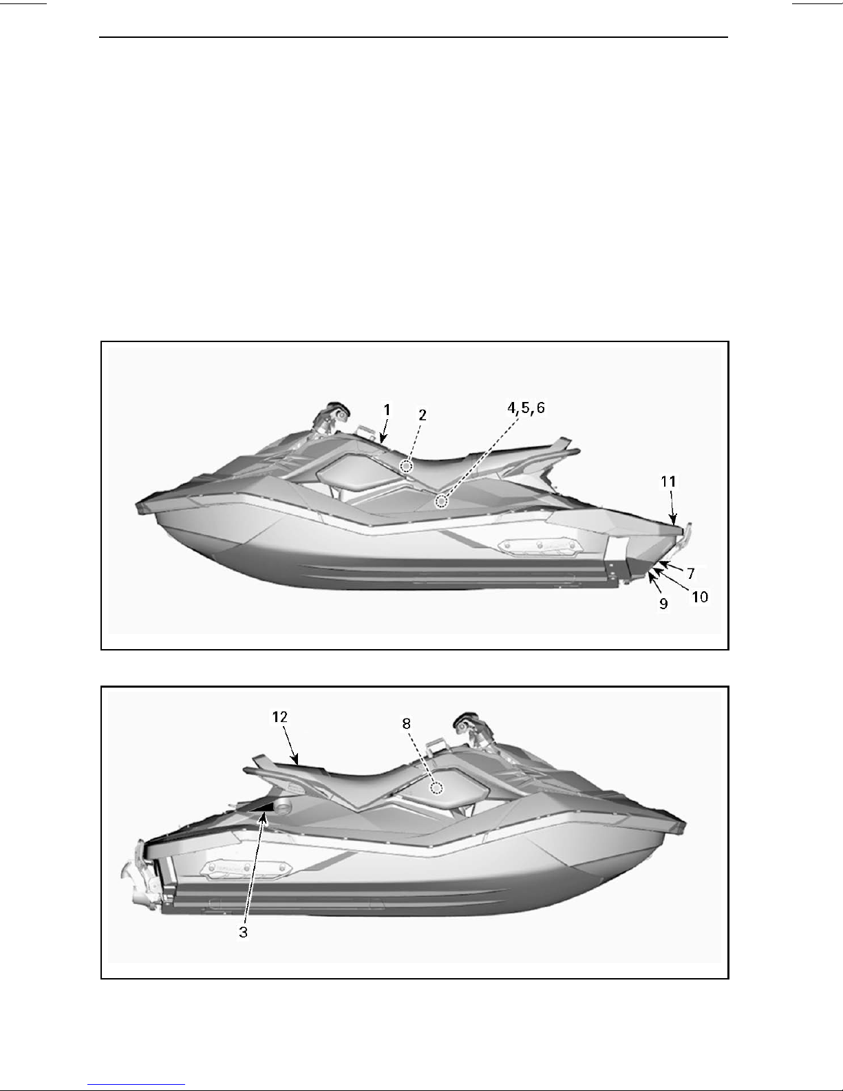
Watercraft Safety Labels
These labels are affixed to the vehicle for the safety of the operator, passenger(s)
or bystanders.
The labels illustrated on the following pages are o n your watercraft. If missing or
damaged, they can be replaced free of charge. See an authorized Sea-Doo dealer.
Please read the following labels carefully before operating this watercraft.
NOTE: The first illustration of the watercraft indicates the approxim ate locations
of the various labels. A dotted line indicates that the label is not on the outer surface,andthattheseatoracoverofsometypemustbeopenedtoseethelabel.
NOTE: In the event of any discrepancy between this guide and the vehicle, the
safety labels on the vehicle have precedence over the labels in this guide.
smo2014-005-061_a
TYPICAL - 3UP - WITH iBR A ND CONVENIENCE PACKAGE SHOWN
smo2014-005-059_b
TYPICAL
28
_______
SAFETY I
NFORMATION
________
Page 31

IMPORTANT ON-PRODUCT LABELS
Collisions result in more INJURIES AND DEATHS than any other type of accident for personal
watercr af t (PWC ).
TO AVOID COLLISIO NS: SCA N CONSTANTLY for poeple, o bjec ts, and
other watercraft. Be alert for conditions that limit your visibilit y or block
your vision of others.
OPERATE DEF ENSIVELY at sa fe speeds and keep a s afe distance away fr om people, objec ts, and others
watercraft. • Do not follow directly behind PWCs or other boats. • Do not go near others to spray or splash them
wit h water. • Avoid sharp t urns or ot her maneuv ers that make it h ard for ot hers to avoid you or understand where
you are goin g.• Avoid areas w ith submerg ed object s or shallow water.
TAKE EARLY ACTION to avoid collisions. Remember, generally PWCs and other boats do not have brakes.
DO NO T RELE ASE TH ROTT LE WHE N TRYING T O ST EER away fro m obje cts - you ne ed throt tle to s teer. Alw ays check
throt tle and st eering controls f or proper opera tion bef ore star ting PWC. Fol low navigati on rules an d province / st ate
and local law s that appl y to PWC s. See oper ator’s guide f or more inf ormation.
To reduce t he risk of S EVERE IN JURY OR DEAT H: WE AR A PER SONAL FL OTATION DEV ICE (PFD ).
All r iders mus t wear a Coas t Guard appr oved PFD that is sui table for personal wat ercraf t (PWC ) use.
WE AR PRO TECT IVE CL OTHING. Se vere int ernal inj uries can occur if water is forced int o body cavi ties as
a resu lt of fall ing into water or bei ng near jet thrust no zzle. Normal swi mwear does n ot
adequate ly protect agains t forceful water en try into lo wer body openin g(s) of mal es or
females. All r iders mus t wear a wet suit bot tom or clothing that pr ivides equivalent
protection (see operat or’s guide) . Foot wear, glove s, and goggles / gl asses are
recommended.
KNO W BOATIN G LAWS. BRP r ecommends a minimum o perator age of
16 year s old. Kno w the opera tor age and t raining requirement s for your pr ovince /
state . A boating safet y course is r ecommended and may be required in y our province /
state.
ATTACH E NGINE SHUT-O FF CORD (L ANYA RD) to PF D and keep it free from
handl ebars so th at engine s tops if operator falls o ff. Af ter riding, remov e cord from
PWC to avoid unaut horized u se by ch ildren or o thers.
RIDE WITHIN YOUR LIMI TS A ND AVOID AG GRESS IV E MANEUV ERS to reduce t he risk of
loss of con trol, eject ion, and col lision. T his is a high p erformance b oat - not a to y. Sharp
turns or ju mping wake s or waves can increase the ris k of back / spinal injury (paralysis) ,
facial inju ries, and b roken legs, ank les, and o ther bone s. Do not jump wak es or waves .
DO NO T APPLY T HROT TLE WH EN ANY ONE IS AT RE AR OF PW C - turn engi ne off or ke ep
engine at id le. Water and / or debris exi ting jet t hrust no zzle can cause severe i njury.
KEEP AWAY F ROM INTAK E GRATE w hile engine is on . Items
such as long hair, loo se clothi ng, or PFD straps can become
ent angled in moving par ts resulting in s evere inj ury or
drowning.
NEVE R RIDE AF TER CONSUMING DR UGS OR AL COHOL .
RE AD AND FOLLO W OPE RATOR ’S GUIDE .
219904030
LABEL 1
________
SAFETY INF
ORMATION
219904030
________
29
Page 32

IMPORTANT ON-PRODUCT LABELS
A219904029D
LABEL 2
• After refueling, always open the
access cover to ensure there is no
gasoline vapor odor inside the
engine compartiment.
• Gasoline vapor may
explosion.
gas tank.
• Keep the
craft away
from open
and
sparks.
• Do not start watercraft
if liquid gasoline or gasoline
vapor odor is present.
• Always replace access
cover before starting.
• Après avoir fait le plein toujours ouvrir le
pas d’émanation d’essence dans le
compartiment moteur.
• Les émanations d’essence
peuvent provoquer des
incendies ou des
explosions.
•Éviter de trop
remplir le
réservoir
d’essence.
• Garder la
motomarine
à l’écart des
et des
étincelles.
• Ne pas démarrer la
motomarine en présence
d’essence liquide ou
• Toujours remettre le couvercle d’accès en
place avant de démarrer la motomarine.
émanation d’essence.
219904029
219904062B
LABEL 3
F18L0NY
LABEL 4
30
_______
SAFETY I
• Remove battery from boat before charging.
• Do not overcharge battery.
• Improper charging of battery can cause explosion.
• Certain components in the engine compartment
may be very hot. Direct contact may result in skin burn.
219904283
LABEL 5
NFORMATION
219904062
219904283
________
Page 33

IMPORTANT ON-PRODUCT LABELS
smo2009-002-111_a
LABEL10-MODELSWITHiBR
F00A2TY
LABEL 6
Heat exchanger in the hull may become
very hot. Avoid any contact with heat
exchanger as burns may occur.
• Make sure engine is off.
• Grab inlet grate and
step on bumper.
• Roll PWC.
219904060B
LABEL 7
219904254
LABEL 11
219904060
smo2014-005-087_a
LABEL12-STAMPEDONREAROFSEATOF
2UP MODELS
219903079
LABEL 8
Moving parts can crush and cut. Keep hands and feet clear.
219904396
LABEL 9- MODELS WITH iBR
________
SAFETY INF
ORMATION
________
31
Page 34

IMPORTANT ON-PRODUCT LABELS
Compliance Labels
smo2014-005-061_b
TYPICAL
smo2014-005-062_b
TYPICAL
32
_______
SAFETY I
NFORMATION
________
Page 35

IMPORTANT ON-PRODUCT LABELS
219902679
LABEL 1 - EMISSION CONTROL LABEL
2
160
352
160
352
2
160
352
160
352
XXXXXXXXX
MAXIMUM CAPACITIES
ABOVE INFORMATION ALSO
APPLIES IN THE
smo2015-005-001_a
LABEL 2 - 2UP MODELS - (WATERCRAFT
OUTSIDE NORTH AMERICA)
U.S.A.
XXXXXXXXX
MAXIMUM CAPACITIES
ABOVE INFORMATION ALSO
APPLIES IN THE
smo2015-005-002_a
LABEL 2 - 2UP MODELS - CANADIAN
COMPLIANCE NOTICE (CAN MODELS
ONLY)
U.S.A.
CAN ICES-2
/ NMB-2”
________
SAFETY INF
ORMATION
________
33
Page 36

IMPORTANT ON-PRODUCT LABELS
3
205
450
205
450
XXXXXXXXX
MAXIMUM CAPACITIES
ABOVE INFORMATION ALSO
APPLIES IN THE
smo2015-005-004_a
LABEL 2 - 3UP MODELS - CANADIAN
COMPLIANCE NOTICE (CAN MODELS
ONLY)
U.S.A.
CAN ICES-2
/ NMB-2”
3
205
450
205
450
XXXXXXXXX
MAXIMUM CAPACITIES
ABOVE INFORMATION ALSO
APPLIES IN THE
smo2015-005-003_a
LABEL 2 - 3UP MODELS - (WATERCRAFT
OUTSIDE NORTH AMERICA)
U.S.A.
34
_______
SAFETY I
ASSEMBLED IN MEXICO
219904272
LABEL 3 - TYPICAL
NFORMATION
219904272
________
Page 37

EMISSION CONTROL INFORMATION
THIS ENGINE IS CERTIFIED TO OPERATE ON
UNLEADED GASOLINE AND CONFORMS TO
U.S. EPA & CALIFORNIA EMISSION / EVAP
REGULATIONS FOR MARINE SI ENGINES.
ENGINE FAMIL Y
ENGINE DISPLACEMENT
EXHAUST EMISSION
CONTROL SYSTEM
RENSEIGNEMENTS SUR LE DISPOSITIF ANTIPOLLUTION
CE MOTEUR EST CERTIFIÉ POUR FONCTIONNER À L'ESSENCE SANS
PLOMB ET IL RÉPOND AUX NORMES DE L'EPA DES É.-U. &
RÉGLEMENTATIONS CALIFORNIENNES POUR LES MOTEURS MARINS À
ALLUMAGE COMMANDÉ.
VOIR GUIDE DU CONDUCTEUR POUR LES SPÉCIFICATIONS D’ENTRETIEN
219904642
FEL
POWER
SEE OPERATOR’S GUIDE FOR MAINTENANCE SPECIFICATIONS
BOMBARDIER RECREATIONAL PRODUCTS INC.
FAMILLE DE MOTEUR
LIMITE DES ÉMISSIONS
DE LA FAMILLE
CYLINDRÉE
SYSTÈME DE CONTRÔLE
DES ÉMISSIONS
PUISSANCE
LABEL 4
AUSTRALIAN BUILDERS PLATE
Imported by BRP Australia Pty Ltd
DATE 2014
Max persons 3 = 205 kg
Max load = 205 kg
Buoyancy Basic Flotation
IMPORTANT ON-PRODUCT LABELS
219904642
WARNING
Alteration of the boat’s hull or permanent
fittings may invalidate the particulars on
this plate.
Information determined - ISO 13590
219904420
219904420
LABEL 5 - 3UP MODELS IN AUSTRALIA
ONLY
________
SAFETY INF
ORMATION
________
35
Page 38

PRE-RIDE INSPECTION
WARNING
Perform a pre-ride inspection before each ride to detect potential problems
during operation. The pre-ride inspection can help you monitor wear and
deterioration before they become a problem. Correct any problems that
you discover to reduce the risk of a breakdown or crash.
Before performing the pre-ride inspection, read and understand the
section.
CONTROLS
What to Do Before Launching the Watercraft
WARNING
Engine should be off and the tether cord cap should always be removed
from the engine cut-off switch prior to verifying any of the following points.
Only start watercraft once all items h ave been checked and operate properly.
Check the items listed in the following table before launching the watercraft.
ITEM OPERATION
Hull Inspect.
Jet pump water intake Inspect/clean.
Drain plug Tighten.
Fuel tank Refill.
Engine compartment
Check for any visible fluid leaks and
gasoline vapor odor.
✓
Engine oil level
Engine coolant level
Heat exchanger condition Inspect.
Steering system Check o peration.
Throttle lever
iBR lever (models with iBR)
Storage bin front cover (if equipped),
glove box cover and seat
Engine cut-off switch and engine
START/STOP button
36
_______
SAFETY I
Check/refill.
Check/refill.
Check operation.
Check operation.
Ensure they are closed and latched.
Check operation.
NFORMATION
________
Page 39

Hull
Inspect hull for cracks and other damages.
Jet Pump Water Intake
Remove weeds, shells , debris or anything else that could restrict the flow of
water and damage the propulsion unit.
Clean as necessary. If any obstruction
cannot be removed, refer to an authorized Sea-Doo dealer for servicing.
NOTE: There is a reinforcement plate
on LH side of hull to maintain symmetry so the hydrodynamics of PWC are
not affected.
PRE-RIDE INSPECTION
smo2014-005-005_a
TYPICAL
1. Bilge drain plug
Step 1: Untighten
Step 2: Tighten
WARNING
Ensure bilge drain plug is properly
secured prior to launching the watercraft in water.
smo2014-005-045_a
TYPICAL
1. Water intake
2. Heat exchanger
3. Reinforcement plate
Drain Plug
Secure bilge d rain plug.
Fuel Tank
Fill the fuel tank.
WARNING
Strictly adhere to instructions detailed in
Engine Compartment
Inspect the engine compartment for
fuel vapor od or.
FUELING PROCEDURE
.
WARNING
Should any leak or gasoline odor
be present, do not apply electrical power or start the engine.You
should seek service from an authorized Sea-Doo dealer, repair shop,
or person of your own choosing
for maintenance, repair, or replacement. Please refer to the
EPA EMISSIONS-RELATED WARRANTY
mation about warranty claims.
contained herein for infor-
US
________
SAFETY INF
ORMATION
________
37
Page 40

PRE-RIDE INSPECTION
To access the engine compartment,
turn the LH access cover knob 1/4 turn
clockwise, then pull out to unsnap the
rear portion and slide rearward to remove.
smo2015-005-005_b
LH A CCESS COVER
1. To lock, turn the knob 1/4 turn
counterclockwise
Engine Oil
smo2015-005-005_a
LH A CCESS COVER
1. To unlock, turn the knob 1/4 turn clockwise
smo2014-005-002
ENGINE COMPARTMENT - LH ACCESS
COVER REMOVED
Reinstall the LH access cover in the reverse of the removal procedure and
lock the knob by turnin g it 1/4 turn
counterclockwise.
Ensure oil level is w ithin specification
as described in
CEDURES
MAINTENANCE PRO-
section.
Engine Coolant
Ensure coolant lev e l is within specification as de scribed in
PROCEDURES
section.
MAINTENANCE
Check for coolant leaks on engine, in
bilge and from heat exchanger.
CAUTION When operating
the engine with the watercraft out
of the water, the engine and heat
exchanger may become very hot.
Avoid any contact with hot engine
parts and the heat exchanger as
burns may occur.
Steering System
If s te erin g is misaligned , follow alignment instructions in
PROCEDURES
section.
MAINTENANCE
38
_______
SAFETY I
Assisted by another person, check
steering operation for free movement.
When the handlebar is horizontal,
the jet pump nozzle should be in the
straight ahead position. Turn the handlebar from left to right and make sure
nozzle turns.
NFORMATION
________
Page 41

PRE-RIDE INSPECTION
WARNING
Check handlebar and corresponding steering nozzle operation before starting. Never turn handlebar while someone is near the rear
of the watercraft. Keep away from
steering moving parts (nozzle, iBR
gate (models with iBR), linkages
etc.).
Throttle Lever
Check the Electronic Throttle Control
lever (ETC) for free and smooth operation. It should return to its initial position immediately after it is released.
WARNING
Check throttle lever operation before starti ng the e ngine. If any friction is felt in the throttle lever, refer
to an authorized Sea-Doo dealer.
iBR Lever (Models with iBR)
Check the iBR lever for free and
smooth operation. It should return
to its initial position immediately after
it is released.
WARNING
Engine Cut-Off Switch and Engine
START/STOP Button
Install the tether cord cap on the engine cut-off switch.
Press the engine START/STOP button to start the engine, then stop it by
pressing the engine START/STOP button a second time.
NOTE: The engine will always start if
the tether cord c ap is properly install.
The ECU will power down after 3 minutes, but if you push the start button, it
will wake-up and start.
Restart the engine, then stop it by removing the tether cord from the engine
cut-off switch.
WARNING
Should the tether cord cap be
looseorfailtoremainontheengine cut-off switch, replace the
tether cord immediately in order
to avoid unsafe use. If removing
the tether cord cap from the engine cut-off switch or pressing the
engine START/STOP button does
not stop the engine, do not use the
watercraft. See your authorized
Sea-Doo dealer.
Check iBR lever operation before
starting the engine. If any friction
is felt in the iBR lever, refer to an
authorized Sea-Doo dealer.
Storage bin (Convenience Package),
Glove Box and Seat
Ensure the storage bin front cover (if
equipped), glove box cover, and seat
are closed and latched.
WARNING
Ensure the seat, glove box cover,
and storage bin front cover (if
equipped) are securely latched.
________
SAFETY INF
What to Do After
Launching the Watercraft
Check the item listed in the following
table after launching the watercraft
and before going for a ride.
ITEM OPERATION
Multifunction
gauge
Intelligent Brake
and Reverse
System (iBR)
(models with
iBR)
ORMATION
________
Check operation
Check operation
✓
39
Page 42

PRE-RIDE INSPECTION
Multifunction Gauge
1. Press engine START/STOP button
andinstallthetethercordcaponthe
engine cut-off switch.
2. As the multifunction gauge cycles
through its self-test function , ensure all indications come on.
WARNING
Always attach the tether cord clip
to your PFD or to the wrist (wrist
strap required).
iBR System (Models with iBR)
NOTICE
space ahead and behind watercraft
to safely carry out the iBR system
test to avoid a collision. Watercraft
will move during test.
1. Remove the moorings securing the
watercraft to the dock.
2. Start the engine and ensure the watercraft does not move.
3. On the left handlebar, depress the
iBR lever completely in, t he watercraft should move slowly backwards.
4. Release the iBR lever, there should
not be any reverse thrust.
Ensure there is sufficient
WARNING
Always ensure proper iBR system
operation before taking the watercraft out for a ride.
40
_______
SAFETY I
NFORMATION
________
Page 43

WATERCRAFT
INFORMATION
_______________
41
Page 44

CONTROLS
NOTE: Some vehicle safety labels are not show n on illustrations. For information
on vehicle safety labels, refer to
WATERCRAFT SAFETY LABELS
subsection.
smo2014-005-050_a
TYPICAL - MODE LS WITHOUT iBR
smo2014-005-051_a
TYPICAL - MODELS WITH iBR
42
______________
Page 45

CONTROLS
1) Handlebar
The handlebar controls the direction of
the watercraft. During forward operation, turning the handlebar to the right
steers the watercraft to the right and
inversely.
smo2014-005-052_a
TYPICAL
1. Handlebar
WARNING
Check handlebar and corresponding steering nozzle operation before starting. Never turn handlebar while someone is near the rear
of the watercraft. Keep away from
the propulsion system.
Waking Up the Electrical System
Press the engine START/STOP button
once witho ut installing the tether cord
on the engine cut-off switch.
This will power up the electrical system; the multifunction gauge will cycle
through a self-test function and will
then go blank after a few seconds.
The electrical system will stay pow ered up for approximately 3 minutes
after the engine START/STOP button
was depressed.
NOTE: If the engine START/STOP button is pressed and held without the
tether cord installed, the multifunction gauge displays will stay on as long
as the engine START/STOP button is
held.
3) Engine Cut-Off Switch
The engine cut-off switch is located on
the RH side of the multifunc tio n g auge.
2) Engine START/STOP
Button
The engine START/STOP button is located on the LH handlebar.
smo2014-005-052_b
TYPICAL
1. Engine START/STOP button
Engine Starting and Stopping
Refer to
subsection for detailed instructions.
OPERATING INSTRUCTION S
smo2014-005-052_c
TYPICAL
1. Engine cut-off switch
To allow engine starting, the tether
cord cap must be securely snapped
onto the engine cut-off switch.
WARNING
Always attach the tether cord clip
to the operator's personal flotation device (PFD) or wrist (wrist
strap required).
_______________
43
Page 46

CONTROLS
smo2014-005-093_a
TYPICAL
1. Tether cord cap on the engine cut-off switch
2. Tether cord clip secured to operator's PFD
To stop engine, pull the tether cord cap
from the engine cut-off switch.
WARNING
Should the engine be stopped, the
brake function (models with iBR)
and watercraft directional control
is lost.
WARNING
smo2014-005-052_d
TYPICAL
1. Throttle lever
The throttle lever is spring loaded and
should return to rest position (idle)
when not pressed.
5) iBR Lever (intelligent
Brake and Reverse)
(Models w ith iBR)
The iBR lever on the LH handlebar can
electronically command:
– Reverse
–Neutral
–Braking.
NOTE: A minimum of 25% lever travel
is required to activate iBR functions.
Always disconnect the tether cord
when the watercraft is not in operation in order to prevent accidental
engine starting or to avoid unauthorized use by others, child ren,
and to prevent theft.
4) Throttle Lever
The throttle lever on the RH handlebar electronically controls the engine
speed.
To increase or maintain watercraft
speed, pull on the throttle lever with
your finger.
To decrease watercraft speed, release
the throttle lev er.
smo2014-005-053 _a
TYPICAL - iBR LEVER
1. iBR lever
2. Lever rest position
3. 25% stroke required to activate iB
4. Operating range
R function
At speeds below 7 km/h (5 MPH),
pulling the iBR lever in will e
ngage re-
verse.
At speeds above 7 km/h (5 MPH),
pulling the iBR lever in w ill engage the
brake.
44
______________
Page 47

When the iBR lever is released after
braking or reverse operation, neutral is
engaged.
WARNING
If the throttle lever is still pulled in
when releasing the iBR lev er, forward movement will be initiated
after a short delay. If forward acceleration is not desired, release
the throttle lever.
CONTROLS
Refer to
subsection for detailed instructions.
NOTE: Braking power is relative to iBR
lever position.
OPERATING INSTRUCTION S
6) Mode Button
The MODE button is located directly
below the multifunction gauge.
smo2014-005-052_e
TYPICAL
1. MODE button
Rotax ACE 900
It is used to scroll through the multifunction displays.
Rotax ACE 900 HO
It is used to activate or deactivate
SPORT mode and to scroll t hrou g h
the multifunction displays.
Refer to
subsection for details.
MULTIFUNCTION GAUGE
_______________
45
Page 48

MULTIFUNCTION G AUGE (LCD)
The multifunction gauge (LCD) is located above the glove box.
Multifunction Gauge
Description
1
34657
smo2014-005-095_a
1. Multifunction display
2. Fuel level display
3. Low fuel level indicator
4. Check engine indicator
5. Engine temperature indicator
6. Low oil pressure indicator
7. Maintenance reminder indicator
Rotax ACE 900 HO
2
Models with iBR
10
smo2014-005-015_b
10. iBR fault indicator
11. GPS satellites synch
1) Multifunction Display
The multifunction display is used to:
– Display the WELCOME message
on power up.
– Activating and setting modes of op-
eration.
– Display scrolling messages of func-
tion activation or system faults.
– Display fault messa ges.
11
smo2014-005-015_a
TYPICAL
8. Touring mode indicator
9. Sport mode indicator
2) Fuel Level Display
Bar gauge continuously indicates the
level of fuel in the fuel tank while riding.
1
2
98
3
smo2014-005-095_b
1. Fuel level display
2. Top segment
3. Bottom segment
When the fuel tank is full, 8 segments
(bars) of the indicator are turned on.
46
______________
Page 49

MULTIFUNCTION GAUGE (LCD)
Whenthefueltankisalmostempty,
the two bottom segments flash and
the low fuel indicator lamp starts flashing.
3) Low Fuel Level Indicator
When this indicator starts flashing, it indicates that there is approximately 12 L
(3.2 U.S. gal.) of f ue l left in fuel tank.
4) Check Engine Indicator
When this indicator is ON, it indicates
an engine fault, look for a message at
the LCD display.
When this indicator b lin ks, it indicate s
that the LIMP HOME mode is activated.
When the check engine indicator
comes on, you may seek service from
an authorized Sea-Doo dealer, repair
shop, or person of your own choosing
for maintenance, repair, or replacement. Please refer to the
US EPA
EMISSIONS-RELATED WARRANTY
contained herein for information about
warranty claims.
Refer to
for more details.
5) Engine Temperature Indicator
TROUBLESHOOTING
section
When this indicator is ON, it indicates
low oil pres sure, look for a message at
the LCD display.
7) Maintenance Reminder Indicator
The maintenance reminder indicator
comes ON when required maintenance is due.
When the m aintenance reminder indicator comes on, you may seek service
from an authorized Sea-Doo dealer,
repair shop, or person of your own
choosing for maintena nce, repair, or replacement. Please refer to the
US EPA
EMISSIONS-RELATED WARRANTY
contained herein for information about
warranty claims.
8) Touring Mode Indicator (Rotax
ACE 900 HO)
When the TOURING m ode indicator is
ON, the default TOURING mode is active.
NOTE: TOURING mode indicator will
turn off once SPORT mode is activated
and will come on again when SPORT
mode is deactivated.
9) Sport Mode Indicator (Rotax ACE
900 HO)
The SPORT mode indicator is normally
off.
When sport mode is selected, the
SPORT mode indicator will come on
and stay on until sport mode is deactivated, or the watercraft is shut down.
When this indicator is ON, it indicates
that engine or exhaust system may be
overheating.
6) Low Oil Pressure Indicator
10) iBR Fault Indicator (Models with
iBR)
_______________
47
Page 50

MULTIFUNCTION GAUGE (LCD)
The iBR fault indicator comes ON
when a fault in the iBR sys tem has
been detected.
Refer to
section for details.
11) GPS Active Indicator (Models
with iBR)
A GPS incorporated in the multifunction gauge provides the speed in the
multifunction display.
This is confirmed when the GPS active
indicator is visible in the digital screen.
TROUBLESHOOTING
sub-
Navigating the
Multifunction Display
WARNING
Do not adjust display while riding,
you could lose control.
Selecting Functions
When the electrical system is powered up and the cluster has completed
itsselftestfunction,aWELCOME
ABOARD SEA-DOO scrolling message will appear for a few seconds.
After the welcome message, the multifunction display will display the last
selected option.
NOTE: You can skip the welcome
message by press ing the MODE button.
NOTE: To change the unit of measurement or the language displayed, see
your authorized Sea-Doo dealer.
1. To selec t the various options avail-
able through the multifunction display, press quickly the MODE button repeatedly until the desired display options is visible:
– SPEED
–RPM
–HOUR
Display O ption Description
Speed
The SPEED can be displayed in km/h
or MPH depending on the unit of measurement setting.
Models with iBR
The speed indication is based on a GPS
(Global Positioning System) incorporated within the multifunction gauge.
If for some reason the GPS signal is
lost, a default mode is used whereby,
the speed is calculated using information received from other systems
to provide an estimated watercraft
speed.
RPM
The RPM is displayed as a numerical
value.
Hour
The HOUR is used to display the a ccumulated engine hours.
The multifunctio n display is also used
to display a menu for the selection of
various functions which permit changing the numerical display indication,
system modes of operation (Rotax
ACE 900 HO), and active system fault
messages.
48
______________
Page 51

EQUIPMENT
NOTE: Illustrations may not be accurate for every model and are only provided as
a visual guide.
NOTE: Some vehicle safety labels are not show n on illustrations. For information
on vehicle safety labels, refer to
WATERCRAFT SAFETY LABELS
subsection.
smo2014-005-059_a
TYPICAL - 2UP MODEL
smo2014-005-060_a
TYPICAL - 3UP MODEL
_______________
49
Page 52

EQUIPMENT
1) Glove Box
A small storage compartment for personal articles, and the
video, located at front of seat.
NOTE: Glove box is not watertight.
Push tab forward to open glove box.
SAFETY DVD
smo2014-005-042_a
1. RH side panel
smo2014-005-006_a
1. Glove box
2. Tab
2) Safety Equipment Kit
Storage Compartment
A small area to store safety equipment
kit or emerge ncy kit only (not supplied
with vehicle).
NOTICE
for general storage. Do not store
any other items in this area. Storing
other items in this area can damage
the vehicle.
To open this storage compartment,
manually release and remove the RH
side panel.
This area is not intended
smo2014-005-043
TYPICAL - RH SIDE PANEL REMOVED
3) Storage Bin
(Convenience Package)
A convenient area to c arry personal articles.
To open the storage bin front cover,
release the lid hooks on each side.
Always close and latch cove r when riding.
50
______________
Page 53

smo2014-005-011_a
TYPICAL
1. Front cover
2. Lid hooks
EQUIPMENT
smo2014-005-092_a
TYPICAL - SEAT LATCH
1. Seat latch handle
Removing the seat provides access
to the rear storage compartment (3UP
models only), operator's guide, the fire
extinguisher (not supplied with vehicle) and the fuel cap.
WARNING
Never carry any loose, heavy,
sharp, or breakable objects in the
storage bin. Do not exceed maximum load capac ity; 2.5 kg (5 lb).
Never operate the watercraft with
the storage bin front cover open.
This is not a watertight compartment.
4) Seat
The seat latch is located under the back
end of the seat.
Toremovetheseat,pushuponthe
latch handle. Release the latch handle
and slide the seat backward.
smo2014-005-004_c
TYPICAL - SEAT REMOVED
1. Fire extinguisher
2. Fuel cap
smo2014-005-086_a
TYPICAL - FLIP SIDE OF REMOV
1. Operator's guide
ED SEAT
_______________
51
Page 54

EQUIPMENT
To install the seat, position the seat in
place and push the seat forward until
the latch clicks.
Pull up on the rear portion of the seat to
ensure it is properly latched.
5) Passenger Handholds
The seat strap provides a handhold for
a passenger to hold on to when riding.
The sides of the molded grab handle at
the rear of the seat also provide a handhold for a passenger.
NOTICE
grab handle to tow anything or to lift
the w atercraft.
Never use the molded
smo2014-005-047_a
TYPICAL
1. Boarding step
WARNING
The engine must be shut off before
attempting to board the watercraft
using the boarding step.
smo2014-005-017_a
TYPICAL - PASSENGER HANDHOLD S
1. Seat strap
2. Molded grab handle
The rear portion of the molded grab
handle also provides a handhold for the
skier/wakeboarder spotter (3up models) or for boarding the watercra ft from
the water.
6) Boarding Step
(Convenience Package)
A convenient step used for boarding
the watercraft from the water.
Pull down the step with your hand and
hold until a knee is put on the step.
smo2014-005-013_a
BOARDING STEP HELD DOWN FOR
BOARDING FROM WATER
52
______________
Page 55

NOTICE
– Never use the step for boarding a
watercraft that is out of wat er.
– Never use the step for pulling,
towing, diving or jumping, or
any other purpose other than as a
boarding step.
– Only one person at a time on the
step.
– Only board the step with a knee,
not a foot.
Models with iBR
EQUIPMENT
WARNING
Be aware of the iBR gate movement when starting the engine,
shutting down the engine or using
the iBR lever. Automatic movement of the gate may squeeze fingers or toes of people taking a hold
on the back or your PWC.
7) Boarding Platform
The rear deck area serves as the boarding platform.
smo2014-005-058_a
TYPICAL - 3UP MODEL
1. Boarding platform
8) Front and Rear Eyelet
Eyelets can be used for mooring, towing a water skier (3UP models), wakeboarder or tuber (3UP models), and as
tie-down points when trailering your
watercraft.
Front Eyelet
smo2014-005-018 _a
TYPICAL - 2UP MODEL
1. Boarding platform
smo2014-005-019_a
TYPICAL
1. Front eyelet
_______________
53
Page 56

EQUIPMENT
Rear Eyelet
smo2014-005-090_b
TYPICAL
1. Rear eyelet
9) Bilge Drain Plug
Unscrew drain plug whenever watercraft is on the trailer. This will allow
water accumulated in the bilge to be
evacuated and helps to reduce condensation.
10) Sponsons
Two fixed sponsons, one on each side
at the rear of the hull, assist in watercraft stability. The sponsons are not
adjustable.
smo2014-005-046_a
1. Sponson
smo2014-005-005_a
TYPICAL
1. Drain plug
Step 1: Untighten
Step 2: Tighten
NOTICE
Ensure drain plug is properly secured prior to launching the
watercraft in water.
54
______________
Page 57

BREAK-IN PERIOD
Operation During Break-In
Period
A break-in period of 5 operating hours
is recommended before running the
watercraft at sustained full throttle.
During this period, maximum throttle
should not exceed 1/2 to 3/4 opening.
However, brief f ull acceleration and
speed variations contribute to a good
break-in.
NOTICE
throttle accelerations or operation,
prolonged cruising speeds are detrimental during the break-in period.
Continued wide open
_______________
55
Page 58

OPERATING INSTRUCTIONS
WARNING
Always perform the
SPECTION
watercraft. Be sure to read the
before operating this
SAFETY INFORMATION
WATERCRAFTINFORMATION
tions and be thoroughly familiar
with the iControl technology.
Should any control or instruction not be
fully understood, refer to an authorized
Sea-Doo dealer.
PRE-RIDE IN-
and the
sec-
Boarding the Watercraft
As with any watercraft, boarding
should be done carefully and engine
must not be running.
WARNING
Engine must be OFF and tether
cord must be removed when
boarding the watercraft or when
using the boarding step. Never
use propulsion system components as a supporting point to
board the watercraft.
smo2014-005-070
Boarding from Water
Ensure there is at least 90 cm (3 ft) of
water underneath the lowest rear portion of the hull.
Take into account that the hull will be
lower in the water when all passengers are aboard. Be certain to maintain
the specified depth so sand, pebbles
and rocks will not be drawn up in the
propulsion system.
Models with iBR
WARNING
Never use the iBR gate as a step
or support to board the watercraft.
Be careful not to bump yourself on
the gate when boarding.
Boarding from a Dock
When boarding from a dock, slowly
place one foot on the watercraft foo
board nearest the dock while holding
the handlebar, and at the same time,
transfer the body weight to the ot
side in order to balance the watercraft.
Then bring the other foot over
and place it on the other footboard.
Push the watercraft away from the
dock.
her
the seat
smo2014-005-100_a
A. Maintain at least 90 cm (3 ft) underneath
the low est rear portion of the hull when all
passengers are aboard
t-
NOTICE
ing the watercraft in shallower water
may damage the propulsion system.
Operator Alone
Starting the engine or rid-
Models Without a Boarding Step
1. Using one hand, grab the rear handle.
56
______________
Page 59

2. With the other hand on the boarding
platform, lift your body until you can
lay one knee on the boarding platform.
OPERATING INSTRUCTIONS
smo2014-005-073
Sit astride the seat.
Models with a Boarding Step
smo2014-005-071
3. Lay the other knee on the boarding
platform.
smo2014-005-072
4. Take hold of the seat strap to help
maintain your balance and step forward onto the footboards on either
side of the seat.
Using one hand, lower the boarding
step.
Using the other hand, take hold of the
edge of the boarding platform, then
pull yourself up so that you can knee
onto the boarding step.
NOTICE
– Never use propulsion system
components to board.
– Only board the step with a knee,
not a foot.
Reachforwardwithonehandandtake
hold of the molded handle behind the
seat, then knee onto the boarding step.
smo2014-005-074
Holdingontothehandlebehindthe
seat, step up onto the boarding platform.
_______________
57
Page 60

OPERATING INSTRUCTIONS
smo2014-005-075
WARNING
Engine must be OFF and tether
cord must be removed when
boarding the watercraft or when
using the boarding step. Never
use propulsion system components as a supporting point to
board the watercraft.
In choppy water, while in the water,
the passenger may hold the watercraft steady to help the operator climb
aboard.
smo2014-005-072
Take hold of the seat strap to help maintain your balance and step forward
onto the footboards on either side of
the seat.
smo2014-005-073
Sit astride the seat.
Operator with a Passenger
smo2014-005-076
The passenger then climbs onto the
watercraft while the operator maintains balance by sitting as close as possible to the console.
smo2014-005-077
The operator climbs on the watercraft
in the same way as explained previously.
58
______________
Page 61

smo2014-005-078
OPERATING INSTRUCTIONS
smo2014-005-079
smo2014-005-080
_______________
59
Page 62

OPERATING INSTRUCTIONS
How to Start Engine
WARNING
Before starting the engine, the operator and passenger(s) should always:
– Be properly seated on the water-
craft
– Have a firm grip on a handhold
or hold on to the waist of the personinfrontofthem
– Wear appropriate protective
clothing including a PFD approved by local authorities and
a w et suit bottom.
– OnmodelswithnoiBR,thePWC
will move forward as soon as
engine is started.
NOTICE
90 cm (3 ft) of water under the lowest rear portion of the hull when all
passengers are aboard prior to starting the engine. Otherwise damage
to the propulsion system components m ay occur.
1. Attach the tether cord clip to your
PFDortothewrist(wriststraprequired).
2. Firmly grip the handlebar with your
left hand and place both feet on the
footboards.
3. Install the tether cord on the engine
cut-off switch.
4. Depress the engine START/STOP
button to crank the engine.
5. Release engine START/STOP button immediately after engine is
started.
Ensure there is at least
NOTICE
START/STOP button more than
10 seconds to avoid starter overheating. A rest period should be observed between the cranking cycles
to allow the starter to cool down.
Do not hold engine
How to Stop the Engine
Models with iBR
WARNING
To maintain watercraft directional
control, the engine should be
running until the watercraft is
stopped.
Models Without iBR
WARNING
The engine must stop running for
the watercraft to come to a full
stop.
All Models
The engine m ay be shut off using one
of two methods:
– Pressing the engine START/STOP
button, or
– Removing the tether cord from the
engine cut-off switch.
WARNING
Never leave the tether cord on the
engine cut-off switch when disembarking watercraft to prevent
theft, accidental engine starting,
and to avoid unauthorized use by
children or others.
WARNING
The tether cord clip should always
be attached to the op
sonal flotation device or to the
wrist (wrist strap required) when
starting or opera
craft.
60
______________
ting the water-
erators per-
Page 63

OPERATING INSTRUCTIONS
How to Steer the
Watercraft
smo2014-005-081_a
Turning the handlebar pivots the jet
pump nozzle which controls the watercraft direction. Turning the handlebar
to the right will turn the watercraft to
the right, turning the handlebar to the
left turns the watercraft to the left.
The throttle should be applied to turn
the watercraft.
WARNING
Throttle should be applied and
handlebar turned to change the direction of the watercraft. Steering
efficiency will differ depending on
the amount of throttle applied, the
number of passengers, the load,
the water co nditions and t he environmental factors such as the
wind.
Unlike a car, a watercraft needs some
throttle to turn. Practice in a safe area
applying the throttle and turning away
from an imaginary object. T his is a
good collision avoidance technique.
WARNING
Directional control is reduced
when the throttle is released and
lostwhentheengineisof
f.
The watercraft behaves differently
with a passenger and requires greater
skill. The passenger(s) should always
grip the seat strap, the molded grab
handle, or the waist of the person
ahead of them. Reduce speed and
avoid sharp turns. Avoid choppy water
conditions when carrying a passenger.
Tight Turns and Other Special
Maneuvers
Any tight turns or special maneuvers
that will cause the air inlet openings to
be kept under water for a prolonged
time, water will seep into the bilge.
Combustion engines need air to operate; consequently this watercraft cannot be totally watertig ht.
NOTICE
are kept under water, such as turning
constantly in tight circles, plunging
the bow through waves, or capsizing the watercraft, water may seep
into the bilge, which may cause severe damage to internal parts of the
engine. Refer to the
section contained in this guide.
O.T.A.S.
(Off-Throttle Assisted Steering)
The O.T.A.S. (Off-Throttle Assisted
Steering) system provides additional
maneuverability in off-throttle situations.
If the d river releases the throttle t o idle
when initiating a full turn, the O .T.A.S.
system will be electronically activated,
and will slightly increase engine speed
to allow completion of the turn.
When the handlebar is brought back
towards its center position, the throt
tle reverts to idle.
We recommend that you fa m iliarize
yourself with this feature during your
first ride.
If the air inlet openings
WARRANTY
TM
System
-
_______________
61
Page 64

OPERATING INSTRUCTIONS
How to Engage Neutral
(Models with iBR)
WARNING
The drive shaft and impeller are
always turning when the engine is
running, even in neutral position.
Keep away from the propulsion
system of the watercraft.
When the watercraft is first started,
the iBR system automatically sets the
neutral position by default.
To engage neutral from forward position, tap the iBR lever.
To engage neutral from reverse position, release the iBR lever and throttle
lever.
How to Engage Forward
(Models with iBR)
To engage forward from neutral position, tap on the throttle lever. The
watercraft will accelerate forward.
How to Engage and Use
Reverse (Models with iBR)
Reverse can only be engaged between
idle speed and the threshold forward
speed of 7 km/h (4 MPH).
To engage reverse position, the iBR
lever on the LH handlebar must be
pulled in at least 25% of the lever
travel.
smo2014-005-053 _a
TYPICAL - iBR LEVER
1. iBR lever
2. Lever released position
3. Approximate 25% position
4. Operating range
To engage forward from reverse position, release the iBR lever, then tap the
throttle lever.
To re-engage forward from braking, simultaneously pull in the throttle lever
while releasin g the iBR lever. The watercraft will accelerate forward after a
short delay.
smo2014-005-063_a
TYPICAL - ENGAGING NEUTRAL
1. Throttle lever
When operating the iBR lever in reverse mode, the throttle lever can
be used to control engine RPM, and
thus the amount of reverse thrust produced.
By modulating throttle lever, reverse
thrust can be more precisely controlled. Too much RPM will create
water turbulence and reduce reverse
efficiency.
NOTE: Engine power will be limited
whenever the iBR lever position is
changed.
Release the iBR lever to end reverse
operation.
To stop rearward motion after iBR lever
release, apply enough throttle to stop
rearward movement.
WARNING
The brake function has no effect
when travelling in reverse.
62
______________
Page 65

OPERATING INSTRUCTIONS
Available engine power is limited in
reverse mode, which limits reverse
speed.
WARNING
Only use reverse at slow speed
and for the shortest time possible.
Always ensure the path behind
is clear of objects, obstacles and
people.
When operating in reverse, turn the
handlebar in the opposite direction
that you want to move the rear of the
watercraft.
For example, to steer the rear of the
watercraft to port (left), turn the handlebar to starboard (right).
How to Engage and Use
Braking (Models with iBR)
WARNING
– The engine must be running to
be able to use the brake.
– The brake is only applicable
when operating in forward
movement, it has no effect on
rearward motion.
– The brake cannot prevent your
PWC from drifting due to current or wind.
The braking function can only be engaged during forward operation at or
above the threshold speed of 7 km/h
(4 MPH).
Braking is engaged and controlled
when the iBR lever on the LH handlebar is pulled in at least 25% of its travel.
smo2014-005-082_a
TYPICAL - STEERING DIRECTION REVERSED
WHEN BACKING
CAUTION Steering direction
in reverse is opposite of forward.
To steer the stern to port (left) in reverse, turn the handlebar to starboard (right). To steer the stern to
starboard (right), turn the handlebar to port (left). Reverse operation
should be practiced in open waters
in order to become full y familiar with
the controls and watercraft handling
characteristics before operating in
close quarters.
_______________
smo2014-005-053 _a
TYPICAL - iBR LEVER
1. iBR lever
2. Lever released position
3. Approximate 25% position
4. Operating range
WARNING
Braking should be practiced in
open waters and at gradually increasing speeds in order to become fully familiar with the controls and watercraft handling characteristics.
When iBR lever is applied, the throttle
lever command is overridden and engine throttle control is now dependant
63
Page 66

OPERATING INSTRUCTIONS
on th e iBR lever position. Braking can
thus be modulated by using only the
iBR lever.
Watercraft deceleration is proportional
to the braking force. The more the iBR
lever is pulled in, the g reater the braking force applied.
NOTE: Be careful to gr adually ac tuate
the iBR lever to adjust intensity of the
braking force and simultaneously release the throttle lever.
CAUTION When braking, riders must brace themselves against
the deceleration force to prevent
from moving forward on the watercraft and losing balance. The operator should always keep both hands
on the handlebars, and all passengers should maintain a firm grip of a
handhold or the waist of the person
infrontofthem.
WARNING
Stopping distance will vary depending on initial speed, load,
wind, number of riders, water conditions, and the amount of braking
power commanded by the operator. Always adjust your riding
style accordingly.
When the watercraft slows to less
than 7 km/h (4 MPH), braking mode
ends and reverse mode is engaged.
Release the iBR lever once the watercraft is stopped. Otherwise, a rearward movement will be initiated.
CAUTION As the watercraft
slows to a stop, the wake created
by the watercraft will catch up and
tend to push the watercraft forward.
Ensure there are no obstacles or
bathers in the direction of travel.
If the throttle lever is still pulled in
when releasing the iBR lever, the watercraft will accelerate forward after a
short delay. Acceleration will be proportional to the throttle lever position.
WARNING
If forward acceleration is not desiredwhenthebrakeleverisreleased, release the throttle lever.
When at speed and the brake is first
applied, a plume of w ater will shoot up
in the a ir behind t he watercraft which
may cause the operator of a following
watercraft to momentarily loos e sight
of your PWC.
WARNING
– It is important to inform the
operator of a watercraft who
intends to follow in a convoy
formation, of the braking and
maneuvering capability of your
PWC, what the plume of water
indicates, and that a greater distance m ust be maintained between watercraft.
– Be aware that other boats fol-
lowing or operating in close
proximity may not be able to
stop as quickly.
Braking in a Turn
Braking can be initiated during a turn
using the iBR lever as previously described. Get ready to maintain yo
balance while the wake is crossing
your PWC.
CAUTION As the watercraft
slows to a stop while braking in a
turn, the wake created by t
craftwillcatchupandtendtopush
the watercraft sideways. Be prepared to maintain balan
wake crossed the watercraft.
he water-
ce as the
ur
64
______________
Page 67

General Operating
Recommendations
Rough Water or Poor Visibility
Operation
Avoid operation in these conditions. If
youmustdoso,proceedwithcaution
using minimum speed.
Crossing Waves
OPERATING INSTRUCTIONS
The operator must grip the handlebar
firmly and keep both feet on the footboards.
The passenger must grip the handholds with both hands and keep both
feet on the footboards.
Reduce speed.
Always be prepared to steer and main-
tain your balance as necessary.
When going over waves, raise your
body slightly off the seat to absorb the
shocks with your legs.
When crossing wakes, always keep a
safe distance from watercraft ahead.
WARNING
When crossing wakes, slow down.
Operator and passenger(s) should
brace themselves and adopt a
semi-standing position to help
absorb the bumps. Do not jump
waves or wakes.
Stopping/Docking
When the throttle is released, the watercraft is slowed by water drag against
the hull. The stopping distance will
vary depending on the watercraft size,
weight, speed, water surface condition, presence and direction of wind
and current.
smo2014-005-083
The operator should practice in open
waters at various speeds to become
familiar with the stopping distances
under different conditions.
Models Without iBR
WARNING
The engine must stop running for
the watercraft to come to a full
stop.
Models with iBR
WARNING
Always practice braking in open
waters ensuring there are no watercraft or boats in your immediate
vicinity, especially astern. Other
users of the waterways may not be
able to maneuver or stop in time
to avoid you should you unexpectedly come to a full stop in front of
them.
The iBR system can also be used for
slowing down or for stopping the
watercraft more quick ly, and for increasing maneuverability especially
when docking. Stopping using the
iBR system in a straight line and in a
turn should be practiced extensively
to bec ome familiar with the handling
characteristics of the watercraft under
partial or full braking conditions.
_______________
65
Page 68

OPERATING INSTRUCTIONS
When at speed and the brake is first
applied, a plume of w a ter will shoot
up in the air behind the watercraft and
may cause the operator of a following
watercraft to momentarily loos e sight
of your PWC.
WARNING
It is important to inform the operator of a watercraft who intends to
follow in a convoy formation of the
braking and maneuvering capability of your PWC, what the plume of
water indicates, and that a greater
distance should be maintained between both of you.
The operator should also practice dockingwithanimaginarydockusingthe
various controls available (iBR lever
and throttle lever).
Release t he throttle at a sufficient distance before the expected landing
area.
Drive slowly towards the beach and
shut off the engine before the water is
less than 90 cm (3 ft) deep under the
lowest rear portion of the hull. Then
pull the watercraft to the beach.
NOTICE
shallow water may result in damage
to the propulsion system components. Always shut off the engine
before the water is less than 90 cm
(3 ft) deep, and never use reverse or
braking.
Riding the watercraft in
Reduce speed to idle.
Maneuver using a combination of the
iBR lever and throttle lever, shifting
to neutral, reverse, or forward as required.
Remember that when operating in reverse, steering direction is reversed.
Turning the handlebars to the left will
move the stern to the right when bac k ingup,andvice-versa.
WARNING
Directional control is reduced
when the throttle is released
and/or when engine is off. Steering direction is reve r sed when operating the watercraft in reverse.
Beaching
NOTICE
run the watercraft to the beach.
It is not recommended to
smo2014-005-083
66
______________
Page 69

OPERATING MODES (ROTAX ACE 900 HO)
Touring Mode
By default, the watercraft is in TOURING mode of operation when first
started.
A TOURING mode indicator is ON in
the m ultifunction gauge to confirm the
active mode of operation.
TOURING MODE INDICATOR
2. Depress and hold the MODE button
foratleast3/4ofasecond.
smo2014-005-052_e
TYPICAL
1. Mode button
Two beeps will be heard and the following message will be displayed in
the multifunction gauge:
Sport Mode
When selected, SPORT MODE provides for instant throttle response and
more rapid accelerations th an TOURING MODE.
A SPORT mode indicator is ON in the
multifunction gauge to confirm the active mode of operation.
Once activated, SPORT MODE will remain active until it is deactivated by the
operator, or the engine is shut down
whereby it defaults back to TOURING
MODE.
Activating Sport Mode
To activate sport m ode, carry out the
following:
WARNING
When activating sport mode, be
sure to maintain situational awareness of other watercraft, obstacles,
or persons in the water.
MESSAGE DISPLAYED
ENTERING SPORT MODE INCREASED ACCELERATION INSTRUCT PASSENGERS TO HOLD PRESS_MODE_BUTTON
WARNING
Ensure passengers are advised
that sport mode provides for increased accelerations and that
they are to hold on tightly.
3. Press the MODE button again to
acknowledge the message and activate sport mode.
One beep will be heard and a sc rolling
SPORT MODE ACTIVATED message
will momentarily confirm that sport
mode has been activated.
1. Start engine.
_______________
67
Page 70

OPERATING MODES (ROTAX ACE 900 HO)
MESSAGE DISPLAYED
SPORT MODE ACTIVATED
NOTE: After a few seconds, the gauge
will revert to its normal display.
4. Ensure the SPORT mode indicator is
turned on.
SPORT MODE INDICATOR
NOTE: The SPORT mode indicator will
comeonandstayonaslongassport
mode is active. If the throttle is not
fully released a nd the engine is not at
idle, SPORT mode cannot be activated.
The following message will then appear in the multifunction gauge.
MESSAGE DISPLAYED
SPORT MODE - RETURN TO IDLE TO
ACTIVATE
Release the throttle. Once the engine
has returned to idle, SPORT mode will
be activated.
Deactivating Sport Mode
To deactivate sport mode, carry out the
following:
WARNING
When deactivating sport mode, be
sure to maintain situational awareness of other watercraft, obstacles,
or persons in the water.
1. Depress and hold the MODE button
for 3/4 of a second.
NOTE: The following message will
scroll in the multifunction display:
SPORT M ODE DEACTIVATED.
68
______________
smo2014-005-052_e
TYPICAL
1. MODE button
Page 71

NOTE: The following message will
scroll in the multifunction display:
SPORT M ODE DEACTIVATED.
MESSAGE DISPLAYED
SPORT MODE DEACTIVATED
NOTE: After a few seconds, the multifunction gauge will revert to its normal
display.
2. Ensure the TOURING mode indic ator is on.
OPERATING MODES (ROTAX ACE 900 HO)
TOURING MODE INDICATOR
_______________
69
Page 72

SPECIAL PROCEDURES
Jet Pump Water Intake and
Impeller Cleaning
WARNING
Keep away from intake grate while
engine is running. Items such as
long hair, loose clothing or personal flotation device straps can
become entangled in moving
parts.
Weeds, shells or debris can get caught
on the in take grate, drive shaft and/or
impeller. A clogged water intake m ay
cause troubles such as:
– Cavitation: Engine speed is high
but watercraft moves slowly due to
reduced jet thrust, jet pump components may be damaged.
– Overheating: Since the jet pump
operation controls the flow of w ater to cool the exhaust system, a
clogged intake will cause the exhaust to overheat and damage exhaust components.
A weed clogged area can be cleaned as
follows:
WARNING
If it is necess ary to reach in to remove any foreign object caught in
the propulsion system, the tether
cord MUST BE REMOVED from the
engine cut-off switch
Models with iBR
If the aforementioned metho d does
not work, the following can be performed:
– With engine running and before ap-
plying throttle, pull the iBR lever in
to select reverse operation and vary
throttle quickly several times.
– Repeat procedure if necessary.
All Models
If system is still blocked, move the watercraft out of the water for cleaning.
Refer to
ING
.
On-Beach Water Cleaning
ON-BEACH WATER CLEAN-
WARNING
The tether cord MUST BE REMOVED from the engine cut-off
switch to prevent accidental engine starting before cleaning the
propulsion system components.
Place a cardboard or a carpet beside
the watercraft to prevent sc ratching
when turning the watercraft for cleaning.
Rotate the watercraft to any side for
cleaning.
In-Water Cleaning
Rock the watercraft several times
while repeatedly pressing engine
START/STOP button for short periods
without starting the engine. Most of
the time, this will remove the blockage. Start engine and make sure watercraft operates properly.
70
______________
Page 73

smo2014-005-049
TYPICAL - 2UP MODEL WITHOUT iBR
SPECIAL PROCEDURES
To turn the watercraft upright, ensure
the engine is off and the tether cord
is NOT ontheenginecut-offswitch.
Then grab the inlet grate, step on a
side bumper rail, and use your weight
to rotate the watercraft towards you.
NOTE: A label on the stern near the
flushing connector provides instructions on how to turn the watercraft
right side up. The label is upside down
sothatitcanbereadwhenthewatercraft is overturned.
Clean the water intake area. If the system is still clogged, refer to an authorized Sea-Doo dealer for servicing.
NOTICE
for damage. Refer to an authorized
Sea-Doo dealer for repair as necessary.
Inspect water intake grate
Capsized Watercraft
The watercraft is designed so that it
should not turn over easily. Two sponsons mounted on the side of the hull,
assist watercraft stability. If it turns
over, it will remain capsized.
WARNING
When watercraft is capsized, do
not attempt to restart the engine.
Operator and passengers should
always wear approved personal
flotation devices.
CAUTION Heat exchanger
in the hull may become very hot.
Avoid any contact with the heat
changer as burns may occur.
ex-
smo2014-005-066_a
When the watercraft is returned to its
normal operating position, the engine
can be started normally.
NOTE: It is recommended to ride the
vehicle for approximately 5 minutes
with engine speed lower than 5000
RPM to e vac ua te any water that might
have been accumulated in the bilge.
Never exceed 5000 RPM. If not, water
could get inside the eng ine.
NOTICE
capsized for more than 5 minutes,
do not attempt to crank the e ngine
to avoid water ingestion that would
damage the engine. See an authorized Sea-Doo dealer as soon as possible.
NOTICE
crank, do not attempt to start it anymore. Otherwise, the engine could
be damaged. See an authorized
Sea-Doo dealer as soon as possible.
If the watercraft has been
If the engine does not
_______________
71
Page 74

SPECIAL PROCEDURES
As soon as possible, check for presenceofwaterinthebilge. Drainas
necessary when back to the shore.
Submerged Watercraft
To limit damages to the engine, perform the following procedure as soon
as possible.
Drain bilge.
If it was submerged in salt water, spray
bilge and all components with fresh
waterusingagardenhosetostopthe
salt corroding effect.
NOTICE
the engine. Water trapped in intake
manifold would flow towards the
engine and possibly cause severe
engine damage.
Bring t he watercra ft to an autho rized
Sea-Doo dealer as soon as possible to
have it serviced.
Never try to crank or start
NOTICE
fore you have the engine serviced,
the greater the damage to the engine will be. Failure to have the engine properly serviced may cause
severe engine damage.
The longer the delay be-
Towing the Watercraft in
Water
Special precautions should be taken
when towing a Sea-Doo watercraft in
water.
The maximum recommended towing
speed is 21 km/h (13 MPH).
Ifyouhavetotowthewatercraft,
clamp the water supply hose in the
engine compartment.
To access the water supply hose, turn
the LH access cover knob 1/4 turn
clockwise, then pull out to unsnap the
rear portion and slide rearward to remove.
NOTICE
fore you have the engine serviced,
the greater the damage to the engine will be.
The longer the delay be-
Water-Flooded Engine
NOTICE
the engine. Water trapped in intake
manifold would flow towards the
engine and possibly cause severe
engine damage.
Bring t he watercra ft to an autho rized
Sea-Doo dealer as soon as possible to
have it serviced.
Never try to crank or start
smo2015-005-005_a
LH A CCESS COVER
1. To unlock, turn the knob 1/4 turn clockwise
WARNING
Some components in the engine
compartment may be hot. To
avoid injury, wait for engine to cool
down.
72
______________
Page 75

CAUTION Make sure the hos e
is properly clamped before towing
the watercraft. If hose is not properly clamped when engine is not
running, water will accumulate in
the exhaust system, will enter the
engine and cause damages.
SPECIAL PROCEDURES
NOTICE
Failure to follow these
instructions may result in damage
to the engine. If you must tow a
stranded watercraft in water, be sure
not to exceed the maximum towing
speed of 21 km/h (13 MPH).
smo2014-005-023_a
1. Water supply hose
Reinstall the LH access cover in the reverse of the removal procedure and
lock the knob by turnin g it 1/4 turn
counterclockwise.
smo2015-005-005_b
LH A CCESS COVER
1. To lock, turn the knob 1/4 turn
counterclockwise
_______________
73
Page 76

SPECIAL PROCEDURES
This page is
intentionally blank
74
______________
Page 77

MAINTENANCE
INFORMATION
_______________
75
Page 78

MAINTENANCE SCHEDULE
Maintenance is very important for keeping the watercraft in a safe operating condition. The watercraft should be serviced as per the maintenance schedule.
A repair shop or person of the owner's choosing may maintain, replace, or repair emission control devices and systems. These instructions do not require
components or service by BRP or authorized Sea-Doo dealers. Although an authorized Sea-Doo dealer has an in -depth technical knowledge and tools to service
the Sea-Doo personal watercraft, the emission-related warranty is not conditioned on the use of an authorized Sea-Doo dealer or any other establishment
with which BRP has a commercial relationship. For emission-related w arranty
claims, BRP is limiting the diagnosis and repair of emission-related parts to the
authorized Sea-Doo dealers. For more information, please refer to the
EMISSION-RELATED WARRANTY
owner’s responsibility. A warranty claim may be denied if, among other things,
the owner or operator caused the problem through improper maintenance or use.
You must follow the instructions for fuel requirements in the fueling section of
this manual. Even if gasoline containing greater than ten volume percent ethanol
is read ily available, the US EPA issued a prohibition against the use of gasoline
containing greater than 10 vol% ethanol that applies to this vehicle. The use of
gasoline containing greater than 10 vol% ethanol with this engine may harm the
emission control system.
contained herein. Proper maintenance is the
US EPA
Disregard the information pertainin g to the follo wing systems if the watercraft is
not equipped with these features:
– iBR (intelligent Brake and Reverse )
Carry out all maintenance as listed in the schedule whenever the hours or time of
each column is reached.
NOTE: As an example, at 200 hours or 2 years, complete all items in this colum n
and ALSO in the EVERY 100 hours or 1 year column.
WARNING
Failure to properly maintain the watercraft accor
schedule and procedures can make it unsafe to operate.
The maintenance schedule does not exempt the pre-
ding to the maintenance
ride inspection.
76
______________
Page 79

MAINTENANCE SCHEDULE
A: ADJUST
C: CLEAN
I: INSPECT
L: LUBRICATE
FIRST50HOURS OR 1 YEAR
EVERY 100 HOURS OR 1 YEAR
EVERY 200 HOURS OR 2 YEARS
R: REPLACE
O: OPERATOR
TO BE PERFORMED BY
RS:REPAIRSHOP
PART/TASKNOTE
ENGINE
Engine oil and filter R RS
Rubber mounts I RS
Corrosion protection
(spray an anti-corrosion lubricant
to metallic components in engine
(1)
L
compartment)
Engine rinsing C
PTO sleeve and seals
(3)
(2)
I, L,
R
(1) Every 10 hours
in sa lt water use.
(2) Daily rinsing
after salt water use.
(3) Replace oil seal and
O
two water seals at 200 hours
(irrespective of number of
O
years). See NOTE 1 at the
end of maintenance schedule
RS
table.
EXHAUST SYSTEM
Exhaust system I, C
(4)
O/RS
COOLINGSYSTEM
Hose and fasteners I RS
Coolant
I
(5)
R
RS
FUEL SYSTEM
iTC lever
Fuel cap, filler neck, fuel tank, fuel tank
straps, fuel lines and connections
(6)
I, L O/RS
II
(7)
RS
Fuel system leak test I I RS
Throttle body and connecting so
intake manifold
cket to
IRS
AIR INTAKE SYS TEM
Air intake silencer I RS
Flame arrestor I RS
ELECTRONIC MANAGEMENT SYSTEMS
(4) Daily flushing after s alt
waterordirtywateruse.
(5) Replace coolant every 300
hours or 5 years
(6)SeeNOTE2attheendof
maintenance schedule table.
(7) After 100 hours of use or
at storage period whichever
comes first.
—
Fault messages I RS
—
_______________
77
Page 80

MAINTENANCE SCHEDULE
A: ADJUST
C: CLEAN
I: INSPECT
L: LUBRICATE
R: REPLACE
O: OPERATOR
RS:REPAIRSHOP
PART/TASKNOTE
ELECTRICAL SYSTEM
Spark plugs I R RS
Electrical connections and fastening
(ignition system, starting system, fuel
injectors, fuse box etc.)
Engine cut-off switch I I RS
Monitoring beeper I I O/RS
Battery and fasteners I
STEERINGSYSTEM
Steering cable and connections I I RS
FIRST 50 HOURS OR 1 YEAR
EVERY 100 HOURS OR 1 YEAR
EVERY 200 HOURS OR 2 YEARS
TO BE PERFORMED BY
II RS
(8) Inspect once a month.
(8)
O/RS
Steering nozzle bushings I I RS
O.T.A.S.
PROPULSION SYSTEM
Rubber boot (drive shaft) I RS
Impeller boot I RS
Impeller shaft seal, sleeve and O-ring I
Drive shaft/impeller splines I, L RS
Drive shaft/PTO splines I, L RS
Sacrificial anode I
Impeller and impeller wear ring clearance I RS
Pump mounts I RS
(9)
II RS
(7)
(10)
RS
O/RS
(9) Inspect operation.
(7) After 100 hours of
use or at storage period
whichever comes first.
(10) Inspect each month (more
often after salt water use) and
change when necessary.
78
______________
Page 81

MAINTENANCE SCHEDULE
A: ADJUST
C: CLEAN
I: INSPECT
L: LUBRICATE
R: REPLACE
O: OPERATOR
RS:REPAIRSHOP
PART/TASKNOTE
iBR SYSTEM (intelligent Brake and Reverse)
iBR lever
iBR gate backlash I I RS
iBR support plates I I RS
iBR friction sleeves I I RS
iBR connecting arm, sleeve and screws I I RS
iBR nut I I RS
iBR boot I I RS
iBR gate bushings I I RS
iBR air chamber I
(6)
FIRST50HOURS OR 1 YEAR
EVERY 100 HOURS OR 1 YEAR
EVERY 200 HOURS OR 2 YEARS
I, L O/RS
(11)
RS
TO BE PERFORMED BY
(6)SeeNOTE2attheendof
maintenance schedule table.
(11) Verify if there is water
inside the air chamber. If
water is present, it means
that the iBR nut has a leak and
needs to be replaced.
iBR protective guard I I RS
HULL AND BODY
Hull I O
Ride plate, heat exchanger, water intake
grate and reinforcement plate
NOTE 1: Inspect for possible leak or damage on oil seal or two water seals, and PTO sleeve surface.
Lubricate grease chamber between the two water seals.
NOTE 2: The iTC and iBR levers should be inspected by depressing and releasing the levers to check for
freedom of movement. If any friction is felt, the lever must be taken apart, cleaned, inspected for
wear and lubricated, refer to an authorized Sea-Doo dealer.
IO
—
_______________
79
Page 82

MAINTENANCE PROCEDURES
NOTE: Some vehicle safety labels are
not shown on illustrations. Fo r information on vehicle safety labels, refer
to
WATERCRAFT SAFETY LABELS
subsection.
This section includes instructions for
basic maintenance procedures.
WARNING
Turn off the engine and follow
these maintenance procedures
when performing maintenance.
If you d o not follow proper maintenance procedures you can be
injured by hot parts, m oving parts,
electricity, chemicals or other hazards.
WARNING
Should removal of a locking device
(e.g. lock tabs, self-locking fasteners, etc.) be required, always replace with a new one.
NOTICE
rag, tool, etc., in the engine compartment or in the bilge.
Engine Oil
Recommended Engine Oil
Use XPS 4-STROKE SYNTH. BLEND
OIL (SUMMER) (P/N 293 600 121) or
XPS 4-STROKE SYNTHETIC OIL (ALL
CLIMATE) (P/N 293 600 112). (If the
recommended XPS
not available, use 5W40 or 10W40 API
SERVICE SN synthetic oil).
Engine Oil Level
NOTICE
and refill if necessary. Do not overfill. Operating the engine with an
improper level may severely damage engine.
Never leave any object,
TM
engine oil is
Check level frequently
CAUTION Certain compo-
nents in the engine compartment
may be very hot. Direct contact may
result in skin burn.
Oil level can be checked with watercraft either in or out of water.
OutofWater
NOTICE
CAUTION When operating
the engine out of water, the heat
exchanger may become very hot.
Avoid any contact with the heat exchanger as burns may occur.
1. Raise trailer tow pole, then block in
position when bumper ra il is level.
2. Install a garden hose on the exhaust
system flushing connector. Refer
to
EXHAUST SYSTEM
tion and follow the procedure.
CAUTION
– Never run engine without supply-
ing water to th e exhaust system.
Failure to cool exhaust system
may severely damage it.
– Never run engine longer than
2 m inutes. Drive line seal has no
cooling when watercraft is out
of water. Also, extreme heat will
damage engine.
3. With the engine already at normal
operating condition, let engine idle
for 30 seconds then stop engine.
4. Wait at least 30 seconds for the oil to
settle in the engine.
Watercraft must be level.
in this sec-
InorOutofWater
5. To check level, remove access
cover located on rear of RH side of
watercraft by turning counterclockwise.
80
______________
Page 83

MAINTENANCE PROCEDURES
smo2014-005-027_a
1. Maximum
2. Minimum
3. Operating range
9. Add oil to ensure the level is between marks as required.
NOTE: Do not overfill.
smo2014-005-024_a
TYPICAL
1. RH access cover
6. Unscrew dipstick, pull it out and
wipe clean.
NOTE: Inner side of RH access cover
is equipped with an extension to facilitate dipstick unscrewing.
smo2014-005-025_a
1. RH access cover - extension side
2. Dipstick
7. Reinstall dipstick, push in completely.
8. Remove dipstick again and read
oil level. It should be between the
MAX and MIN marks.
To add oil:
– Place a funnel in the oil neck open-
ing.
– Add the recommen ded oil to the
proper level.
NOTE: Every time oil is added in the
engine, the complete procedure explained in this section must be carried
out again. Otherwise, you will obtain a
false oil level reading.
10. Properly reinstall dipstick and RH
access cover.
Engine Oil Change and Oil Filter
Replacement
The oil change and filter replacement
may be performed by an authorized
Sea-Doo dealer, repair shop, or person
of your own choosing.
Engine Coolant
Recommended Engine Coolant
Always use LONG LIFE ANTIFREEZE
(P/N 219 702 685) or equivalent. If
the recommended coolant is not available, use a low silicate, extended
life ethylene-glycol premixed coolant
(50%-50%) specifically formulated
for internal combustion aluminum engines.
To prevent antifreeze deterioration, always use the same brand and gra de.
Never mix different brands or grades
unless cooling system is completely
flushed and re fille d.
_______________
81
Page 84

MAINTENANCE PROCEDURES
Engine Coolant Level
WARNING
Check coolant level with engine
cold. Never add coolant in cooling
system when engine is hot.
CAUTION Certain compo-
nents in the engine compartment
may be very hot. Direct contact may
result in skin burn.
To access the expansion tank, turn the
LH access cover knob 1/4 turn clockwise, then pull out to unsnap the rear
portionandsliderearwardtoremove.
With watercraft on a level surf ace,
add coolan t until it is visible without
exceeding the COLD level mark in
coolant reservoir when engine is cold.
smo2014-005-029_a
1. Cold level mark
NOTE: The watercraft is level when
it is in water. When on a trailer, raise
trailer tow pole and block in th is position when bumper rail is level.
smo2015-005-005_a
LH A CCESS COVER
1. To unlock, turn the knob 1/4 turn clockwise
Locate the expansion tank cap.
smo2014-005-028_a
1. Expansion tank cap
Add premixed coolant to adjust coolant
level between marks as required. Use
a funnel to avoid spillage. Do not overfill.
Properly reinstall and tighten expansion tank cap, then reinstall the LH
access cover in the reverse of removal
procedure and lock the knob by turning
it 1/4 turn counterclockwise.
smo2015-005-005_b
LH A CCESS COVER
1. To lock, turn the knob 1/4 turn
counterclockwise
82
______________
Page 85

MAINTENANCE PROCEDURES
NOTE: A cooling system that fre-
quently requires coolant is an indication of leaks or engine problems. See
an authorized Sea-Doo dealer.
Engine Coolant Replacement
Coolant replacement should be performed by an authorized Sea-Doo
dealer.
Steering Alignment
1. Manually release and remove the
LH side knee pad.
NOTE: This area is intended only to access the steering cable assembly. Do
not use this area for storage purposes.
3. Put the jet pump nozzle in straight
position.
4. Unscrew nut to turn handlebar to
the right.
5. Screw nut to turn handlebar to the
left.
6. When steering alignm e n t is com plete, clip the steering cable by
pushing the ring back down and reinstalling the LH side knee pad.
Central Body
Central Body Removal
When necess ary, remove the central
body as follows:
WARNING
Neverattempttoliftthecentral
body alone. Lift only with assistance or use an a ppropriate lifting
device. Lifting alone can cause serious injury.
smo2014-005-032_a
1. LH Side knee pad
2. Unclip the steering cable by pushing
theringuptowardsthenut.
smo2014-005-033_a
STEERING CABLE UNCLIPPED
1. Ring
2. Nut
1. Turn the LH access cover knob 1/4
turn clockwise, then pull out to unsnap the rear portion and slide rearward to remove.
smo2015-005-005_a
LH A CCESS COVER
1. To unlock, turn the knob 1/4 turn clockwise
2. Disconnect the steering connector.
_______________
83
Page 86

MAINTENANCE PROCEDURES
smo2014-005-034_a
1. Connector
3. Manually release and open the LH
side knee pad and disconnect steering cable assembly.
4. Remove two screws from the cable
assembly.
smo2014-005-091_a
1. Cable assembly screws
smo2014-005-032_a
1. LH side knee pad
5. Remove nut, bolt, and washer to
disconnect rod from steering column.
smo2014-005-064_a
1. Nut and washer
2. Bolt
3. Rod
6. Remove two self-tapping screws
from each rear panel trim at rear of
vehicle.
smo2014-005-044_a
TYPICAL - LH SIDE KN
1. Steering cable assembly
84
______________
EE PAD REMOVED
7. To remove the rear panel trims, slide
trims towards the outside of PWC.
Page 87

smo2014-005-090_a
1. Rear panel trims
8. Remove seat. Refer to
EQUIPMENT
subsection.
SEAT
in
9. Remove three self-tapping screws
around the fuel cap
MAINTENANCE PROCEDURES
smo2014-005-089_c
1. Self-tapping screws
12. Remove ten M6 nuts and screws
from both sides of central body.
smo2014-005-004_b
1. Screws
10. Remove five self-tapping screws
at front of central body.
NOTE: If equipped w ith a storage bin,
open the storage bin first. Refer to
STORAGE BIN
smo2014-005-089_b
1. Self-tapping screws
subsection.
11. Remove six self-tapping screws at
rear of central body.
smo2014-005-089_a
1. Nuts and screws
13. Carefully lift the central body off
the hull using a lifting belt.
NOTE: When lifting central body, wrap
belt around handlebars. Wrapping belt
elsewhere on central body to lift it may
cause damages.
Central Body Installation
1. Properly place central body align-
ment tabs on hull.
smr2014-041-017_a
CENTRAL BODY - STARBOARD SIDE VIEW
1. Grooved alignment tab on c entral body
2. Ribinhull
_______________
85
Page 88

MAINTENANCE PROCEDURES
2. Install screws adjacent to alignment
tabs first to ensure alignment tabs
remain properly engaged.
smr2014-041-002_a
1. Screws adjacent to alignment tabs
3. Install two screws on rear support.
5. Install and tighten screws on front
and rear of central body to the recommended torque.
smo2014-005-089_b
1. Self-tapping screws
smr2014-041-003_a
1. Screws on rear support
4. Install screws and tighten nuts on
both sides of central body to the
recommended torque.
smo2014-005-089_a
1. Nuts and screws
TIGHTENING TORQUE
M6 nuts
3.5 N•m ± 0.5 N•m
(31 lbf•in ±4lbf•in)
smo2014-005-089_c
1. Self-tapping screws
TIGHTENING TORQUE
Self-tapping
screw
5.5 N•m ± 0.5 N•m
(49 lbf•in ±4lbf•in)
6. Install and tighten self-tapping
screws around the fuel cap to the
recommended torque.
smo2014-005-004_b
1. Screws
86
______________
Page 89

MAINTENANCE PROCEDURES
TIGHTENING TORQUE
Self-tapping
screw
7. Reinstall the seat. Refer to
EQUIPMENT
4.5 N•m ± 0.5 N•m
(40 lbf•in ±4lbf•in)
SEAT
subsection.
in
8. Position rear panel trims in place by
sliding towards the inside of PWC
and install self-tapping screws.
Tighten to the recommended
torque.
10. Connect steering cable in reverse
of removal procedure.
11. Close knee pad and LH access
cover and lock the knob by turning it 1/4 turn counterclockwise.
smo2015-005-005_b
LH A CCESS COVER
1. To lock, turn the knob 1/4 turn
counterclockwise
Battery
smo2014-005-090_a
1. Rear panel trims
TIGHTENING TORQUE
Self-tapping
screw
5.5 N•m ± 0.5 N•m
(49 lbf•in ±4lbf•in)
9. Connect the steering connector.
Battery Access
Turn the LH access cover knob 1/4 turn
clockwise, then pull out to unsnap the
rear portion and slide rearward to remove.
smo2015-005-005_a
LH A CCESS COVER
1. To unlock, turn the knob 1/4 turn clockwise
smo2014-005-034_a
1. Connector
_______________
87
Page 90

MAINTENANCE PROCEDURES
Battery Removal
WARNING
The BLACK (-) battery cable must
always be disconnected first and
reconnected last. Never charge
or boost battery while installed in
watercraft.
1. Disconnect the BLACK (-) battery cable.
2. Slide the RED rubber protector off
the RED (+) cable terminal and disconnect it from the battery post.
3. Reinstall bolts to secure retaining
nuts during removal.
4. Detach retaining strap.
smr2014-033-011_a
CENTRAL BODY REMOVED FOR CLARITY
PURPOSE
1. BLACK (-) cable
2. RED (+) cable
3. Retaining strap
5. Remove battery from vehicle.
smr2014-033-012
Battery Cleaning
Clean the battery casing, cables and
battery posts using a solution of baking
soda and water.
Remove corrosion from battery cable
terminals and battery posts using a
firm wire brush.
Battery top should be cleane d with a
soft brush and any grease-cutting soap
or baking soda solution.
Rinse with clear water then dry well.
Battery Inspection
Visually inspec t battery casing for
cracks, leaks or other possible damages.
Discoloration, warping or raised top, indicates that the battery has overheated
or been overcharged.
If the casing is damaged, replace battery and thoroughly clean battery tray
and surrounding area with a water and
baking soda solution.
NOTICE
Should any electrolyte
spillage occur, im mediately wash off
area with a solution of baking soda
and water, then rinse thoroughly.
88
______________
CAUTION Should the battery
casing be damaged, wear a suitable
pair of non-absorbent gloves when
removing the battery by hand.
Inspect the battery posts for security of
mounting.
Page 91

MAINTENANCE PROCEDURES
Battery Storage
NOTICE
Battery storage is critical
for battery life. Regularly charging
the battery during storage will prevent cell sulfation. Keeping the battery in vehicle for storage m ay lead
to contacts degradation/corrosion
and case damage if freezing occurs.
A discharged battery will freeze and
crack in areas where freezing conditions are experienced. Electrolyte
leakage will damage surrounding
parts. Always remove battery from
vehicle for storage and regularly
recharge it to keep an optimal condition.
Clean battery te rminals and cable connections using a wire brush.
Apply a light coat of dielectric grease
on terminals.
Clean battery casing using a solution of
baking soda and water.
Rinse battery with clear water and dry
well using a clean cloth.
Store battery in a cool dry place. Suc h
conditions reduce self-discharging and
keep fluid evaporation to a minimum.
Keep battery away from dew, high
moisture and direct sunlight.
Recharge frequency depends on battery condition and storage temperature. Maintain battery as per following
table.
NOTE: The battery must always be
stored in fully a charged state.
AMBIENT
TEMPERATURE
Below 16°C (60°F)
Above 16°C
(60°F)
CHARGING
FREQUENCY
Every month
Every 2 weeks
Charging a Battery
WARNING
Never charge or boost the battery
while installed in the watercraft.
WARNING
Always wear safety glasses and
charge the battery in a ventilated
area. Never charge or boost a battery while installed on a vehicle.
Do not open the sealed caps during charging. Do not place battery
near an open flame.
NOTICE
hot to the touch, stop charging and
allow it to cool before continuing.
NOTE: Sealed VRLA batteries have an
internal safety valve. If battery pressure increases due to overcharging,
the valve opens to release excess pressure, preventing battery damage.
Carryoutabattery
METER TEST
section, then proceed as described
here.
An automatic charger is the fastest and
most convenient way for error-proof
charging.
When using a constant current
charger, charge battery according to
the chart below.
Battery Voltage Below 12.8 V and
Above11.5V
YTX20L-BS TIME CHARGE
STANDARD
CHARGING
(RECOMMENDED)
If the battery becomes
UNLOADED VOLT-
as described in this sub-
4-9
hours
2A
QUICK
CHARGING
50
minutes
10 A
_______________
89
Page 92

MAINTENANCE PROCEDURES
Battery Voltage Below 11.5 V
A battery with a voltage below 11.5 V
requires a special procedure to
recharge. In charging an over discharged battery, its internal resistance
may be too high to charge at a normal
charging rate.
Set charger to the 10 A charging rate
and monitor charging current for approximately 30 minutes. If there is no
change in charging current or battery
becomes abnormally hot, the battery
is most likely at the end of its se rvice
life and should be replaced.
Battery Installati on
1. Install the battery in the watercraft
and secure it using retaining strap.
WARNING
Always connect battery cables in
the specified order, RED (+) cable
first, BLACK (-) cable last.
– Clean terminals and connectors if
necessary.
– For storage, pull battery or discon-
nect battery cables.
Ignition Coils
Ignition Coil Removal
1. To access the ignition coils, remove
the central body. Refer to
BODY REMOVAL
NOTICE
tion coil before disconnecting the
input connector or the wires may be
damaged. Do not pry up ignition coil
with a screwdriver to avoid damage.
2. Disconnect ignition coil connector.
3. Remove ignition coil retaining
screw.
4. Remove ignition coil from spark plug
by rota ting coils side to side as you
pull up.
Do not remove the igni-
section.
CENTRAL
2. Connect RED (+) cable.
3. Connect BLACK (-) cable last.
4. Apply dielectric grease on battery
posts.
5. Verify cable routing and attachments.
6. Install remaining removed components.
Battery maintenance
These batteries require little maintenance to perform perfectly. Follow
this simple check list for optimum battery performance:
– Check voltage every 3 months using
a voltmeter.
– Keep a battery fully charged to
100% (12.8 V or higher after standing2hours).
– Check and charge b attery if the volt-
age drops below 12.5 V.
– Keep the battery top free of grime.
smr2014-032-001_a
1. Ignition coils
Ignition Coil Installation
1. Align the retaining screw hole of the
ignition coil with the threaded hole
on the valve cover.
2. Install the ignition coil on the spark
plug and push it all the way down
until it rests on the valve cover.
3. Install the retaining screw and
tighten to specification below.
90
______________
Page 93

MAINTENANCE PROCEDURES
IGNITION COIL RETAINING SCREW
Tightening torque 11 N•m (97 l bf•in)
4. Connect ignition coil connector.
Spark Plugs
Spark Plug Removal
1. Disconnect the ignition coil input
connector.
2. Remove ignition coil. Refer to
TION COIL REMOVAL
.
IGNI-
WARNING
Never remove an ignition coil from
a spark plug without disconnecting it from the wiring harness.
Flammable vapors may be present
in the bilge. Should the tether cord
be installed on the engine cut-off
switch, a spark could be generated
at the c oil spark plug end which
could cause an explosion.
Spark Plug In stallation
Prior to installation, ensure the contact
surfaces of the cylinder head and spark
plug are free of grime.
WARNING
Do not adjust gap on this type of
spark plug. The adjustment could
weaken negative electrodes which
may lead to electrode breaking
and severe engine damage.
1. Using a wire feeler gauge, check
electrode gap as specified in
NICAL SPECIFICATIONS
2. Apply LOCTITE 767 (ANTISEIZE LUBRICANT) (P/N 293 800 070) over
the spark plug threads to prevent
possible seizure.
3. Hand screw spark plug into cylinder
head. Then, tighten the spark plug
clockwise to the specified torque
with an approved spark plug socket.
TECH-
.
3. Using a spark plug socket, release
the torque applied to the spark plug.
1
A00E0BA
1. Approved socket
2. Improper socket
2
4. Clean the spark plug and cylinder
headwithpressurizedair.
5. Unscrew spark plug then use the
ignition coil to take spark plug out of
spark plug hole.
SPARK PLUG TORQUE
NGK CR8EB (or
equivalent)
4. Install ignition coil. Refer to
TION COIL INSTALLATION
13 N•m ± 1 N•m
(115 lbf•in ±9lbf•in)
IGNI-
.
Reinstall the central body Refer to
CENTRAL BODY INSTALLATION
sec-
tion.
Exhaust System
Exhaust System Flushing
Flushing the exhaust system with
fresh water is essential to neutralize
corroding effects of salt or other chemical products present in water. It will
help to remove sand, salt, shells or
other particles in wa ter jackets and/or
hoses.
_______________
91
Page 94

MAINTENANCE PROCEDURES
Flushing should be performed when
the watercraft is not expected to be
used further the same day or when the
watercraft is stored f or any extended
time.
WARNING
Perform this operation in a well
ventilated area.
Proceed as follows:
Clean propulsion system by spraying
water in its inlet and outlet and then
apply a coating of XPS Lube or equivalent.
CAUTION When operating the
engine while the watercraft is out of
the water, the heat exchanger may
become very hot. Avoid any contact
with heat exchanger as burns may
occur.
Connect a garden hose to the connector located at the rear of watercraft (on
the port side of the stern). Do not open
water tap at this time.
CAUTION Certain compo-
nents in the engine compartment
may be very hot. Direct contact may
result in skin burn. Do not touch any
electrical parts o r propulsion system
component when the engine is running.
NOTICE
gine. Always start the engine before
opening the water tap. Open water tap immediately after engine is
started to prevent overheating.
Run the engine 90 seconds at idle
speed.
NOTICE
supplying water to the exhaust system wh en watercraft is out of water.
Ensure water flows out of jet pump
while flushing. Otherwise, refer to an
authorized Sea-Doo de ale r for servicing.
Close the water tap, run the engine at
5000 RPM for 5 seconds and stop the
engine.
Never flush a hot en-
Never run engine without
NOTICE
before opening the water tap. If not,
water will get inside the engine.
smo2014-005-069_a
JET NOZZLE REMOVED FOR CLARITY
1. Flushing connector location (with optional
hose adapter shown)
NOTE: An optional quick connect hose
adapter and hose fitting can be used
(P/N 295 100 555). No hose pincher is
required to flush engine.
To flush, start engine then immediately
open the water tap.
Always run the engine
NOTICE
tap before stopping the engine. If
not, water will get inside the engine.
NOTICE
adapter after flushing operation (if
used).
Always close the water
Remove quick connect
Heat Exchanger and Water
Intake Grate
Heat Exchanger and Water Intake
Grate Inspection
Inspect heat exchanger and jet pump
water intake grate for cracks and other
damages. See your Sea-Doo dealer
to have any damaged part repaired or
replaced.
92
______________
Page 95

MAINTENANCE PROCEDURES
WARNING
The tether cord must always be
removed from the engine cut-off
switch prior to inspecting the intake grate.
NOTE: There is a reinforcement plate
on LH side of hull to maintain symmetry so the hydrodynamics of PWC is not
affected.
Sacrificial Anode R emoval
Unscrew sacrificial anode retaining nut
and remove anode.
Sacrificial Anode Installation
Installation is the reverse of the removal procedure.
Torque anode retaining nut as specified
in exploded view.
Fuses
Fuse Removal and Installation
Use the fuse remover/installer included in the fuse box to ease fuse
removal.
Fuse Inspection
If an electrical problem occurs, check
the fuses. If a fuse is burnt, replace by
one of the same rating.
smo2014-005-045_a
1. Water intake
2. Heat exchanger
3. Reinforcement plate
Sacrificial Anode
Sacrificial Anode Inspection
Check for wear. If worn more than half,
replace anode.
smr2014-039-001_a
1. Sacrificial anode location
1
2
3
A15E0KZ
1. Fuse
2. Check if melted
3. Ampere rating
WARNING
Do not use a higher rated fuse
as this can cause severe damage. If a fuse has burnt out, the
source of the malfunction should
be determined and corrected before restarting. See an authorized
Sea-Doo dealer for servicing.
_______________
93
Page 96

MAINTENANCE PROCEDURES
Fuse Location
All fuses are located inside a single
fuse box.
To access the fuse box,turn the knob
1/4 turn clockwise, then pull out to
unsnap the rear portion and slide rearward to remove.
smo2015-005-005_a
LH A CCESS COVER
1. To unlock, turn the knob 1/4 turn clockwise
smo2014-005-041_a
TYPICAL - FUSE BOX COVER REMOVED
1. Fuse box
NOTE: Fuse ratings and positions are
illustrated on the fuse box cover.
To reinstall the fuse box cover and the
LH access cover, do the reverse of the
removal procedure and lock the knob
by turning it 1/4 turn counterclockwise .
The fuse box is located to the left of the
expansion tank.
To remove the fuse box cover, squeeze
and hold locking tabs on both sides of
thefuseboxandpullthecoveroffthe
fuse box.
smo2014-005-002_a
1. Fuse box cover
2. Locking tabs
3. Expansion tank
smo2015-005-005_b
LH A CCESS COVER
1. To lock, turn the knob 1/4 turn
counterclockwise
Fuse Description
FUSE RATING DESCRIPTION
ECM, Cluster, Starter
1
25A
10 A
Solenoid, OTAS and
CAPS
Engine START/STOP
button
94
______________
3 15 A Battery
4
5
30 A
30 A iBR
Charge
Page 97

WATERCRAFT CARE
Remove the watercraft from the water
every day.
Post-Operation Care
Exhaust System Flushing
The exhaust system should be flushed
daily when watercraft is used in sa lt or
foul water.
Refer to
DURES
Additional Care for Foul Water or
Salt Water Operation
When the watercraft is operated in foul
water and particularly in salt water, additional care should be taken to protect
the watercraft and its components.
Rinse watercraft bilge area with fresh
water.
Never use a high pressure washer to
clean the bilge. USE LOW PRESSURE
ONLY (such as a garden hose).
High pressure can cause damages to
electrical or mechanical systems.
CAUTION Allow engine to
cool before performing any maintenance.
NOTICE
care such as: watercraft rinsing, exhaust system flushing and anticorrosion treatment, when watercraft is
used in salt water, will result in damage to the watercraft and its components. Never leave the watercraft
stored in direct sunlight.
MAINTENANCE PROCE-
.
Failure to perform proper
(P/N 219 701 709), or the equivalent,
which does not damage textured plastic.
NOTICE
with strong detergent, degreasing
agent, paint thinner, acetone, or
other strong chemical or petroleum
type cleaner, such as XPS SPRAY
CLEANER & POLISH (P/N 219 701
706), that can damage textured plastic.
Stains may be removed from the seat
using BRP HEAVY DUTY CLEANER
(P/N 293 110 001) or the equivalent,
whichissafeonvinylandmetalsurfaces.
NOTICE
DUTY CLEANER (P/N 293 110 001)
on plastic parts. This product can
damage textured plastic.
Never clean plastic parts
Never use BRP HEAVY
WARNING
Never apply plastic or vinyl protectoronthewetgripfloorboardarea
or seat as the surface will become
slippery and the occupants may
slip off the watercraft.
Respect the environment by ensuring
fuel, oil or cleaning solutions do not
drain into the waterways.
Watercraft Cleaning
Body and Hull
Occasionally, wash the hull and various
body components w ith water and soap
(use only mild detergent). Remove any
marine organisms from engine and/or
hull. Soiled surfaces can be cleaned
with XPS ALL PURPOSE CLEANER
_______________
95
Page 98

STORAGE AND PRESEASON PREPARATION
Storage
WARNING
Because fuel and oil are
flammable, you should have
an authorized Sea-Doo dealer,
repair shop, or person of your
own choosing to inspect the fuel
system integrity as specified in the
periodic inspection chart.
It is recommended that the watercraft
be serviced by an authorized Sea-Doo
dealer, repair shop, or person of your
own choosing, however the following
operations can be performed by you
with a minimum of tools.
NOTE: Carry out the following tasks in
the same order as detailed in this section.
NOTICE
ing the storage period.
Propulsion System
Do not run the engine dur-
Fuel System
Fuel System Protection
XPS FUEL STABILIZER (P/N 413 408
601) (or equivalent) should be added in
the fuel tank to prevent fuel deterioration and fuel system gumming. Follow
stabilizer manufacturers' instructions
for proper use.
NOTICE
to add fuel stabilizer at storage in order to maintain fuel system in good
condition. Fuel stabilizer should
be added prior to engine lubrication and fuel tank top up to ensure
fuel system components protection
against varnish deposits.
Fill up fuel tank completely as explained in
sure there is no water inside fuel tank.
NOTICE
trapped inside fuel tank, severe internal damage will occur to the fuel
injection system.
It is highly recommended
FUELING
Should any water be
section. Make
Jet Pump Cleaning
Clean jet pump by spraying water in its
inlet and outlet and then apply a coat of
XPS LUBE (P/N 293 600 016) or equivalent.
WARNING
Always remove tether cord from
the engine cut-off switch to pr event unexpected e ngine starting
before cleaning the propulsion
system components. Engine must
not be running for this operation.
Jet Pump Inspection
Remove impeller cove r and check if jet
pump is water contaminated; if so, see
your authorized Sea-Doo dealer.
Engine and Exhaust Systems
Exhaust System Flushing
Perform procedure as described in
MAINTENANCE PROCEDURES
Engine Oil and Filter Replacement
The oil change and filter replacement
may be performed by an authorized
Sea-Doo dealer, repair shop, or person
of your own choosing.
Exhaust System Draining
In areas where temperature may
freeze, water trapped in the exhaust
system must be removed.
Using the flushing connector located
on the port (LH) side of the stern, inject
pressurized air at 379 kPa (55 PSI) into
system until there is no more water
flowing from jet pump.
.
96
______________
Page 99

smo2014-005-069_a
JET NOZZLE REMOVED FOR CLARITY
1. Flushing connector (with optional hose
adapter shown)
The following hose can be fabricated to
ease draining procedure.
STORAGE AND PRESEASON PREPARATION
7. Apply a small amount of anti-seize
lubricant on spark plug threads, then
reinstall them in the engine. Refer
to
MAINTENANCE PROCEDURES
8. Install the ignition coils, refer to
MAINTENANCE PROCEDURES
.
Engine Coolant Test
If antifreeze is not replaced, test its
density.
The antifreeze replacement and a density test should be performed by an authorized Sea-Doo de ale r.
NOTE: Antifreeze should be replaced
every 300 hours or e very 5 years to
prevent antifreeze d eterioration.
.
smo2008-001-053_a
1. Flushing connector adapter (P /N 295 500
473)
2. Hose 12.7 mm (1/2 in)
3. Air hose male adapter
NOTICE
Failure to drain the exhaust system may cause severe
damage to the exhaust manifold.
Remove special tools.
Engine Internal Lubrication
1. Remove the central body. Refer
to
CENTRAL BODY REMOVAL
in
MAINTENANCE PROCEDURES
section.
2. Remove ignition coils, refer to
MAINTENANCE PROCEDURES
3. Remove spark plugs, refer to
TENANCE PROCEDURES
4. Spray XPS LUBE (P/N 293 600 016)
or equivalent in spark plug holes.
5. To prevent fuel from being injecte
and to disable the ignition during engine cranking, fully depress throttle
lever and HOLD against handle
6. Press the engine START/STOP but-
tontocranktheengineafew
This will distribute the oil on the
cylinder walls.
.
.
MAIN-
bar.
turns.
NOTICE
Improper antifreeze density may result in freezing of the liquid in the cooling system if the watercraft is stored in an area where
the freezing point is attained. This
could seriously damage the engine.
Electrical System
Battery Removal and Charging
Refer to
PROCEDURES
BATTERYinMAINTENANCE
section.
Engine Compartment
Engine Compartment Cleaning
Clean the bilge using hot water an d a
mild detergent or with bilge cleaner.
Rinse thoroughly.
Lift front end of watercraft to com-
pletely drain bilge through the bilge
drain plug.
Anticorrosion Treatment
Wipe off any residual water in the en-
d
gine compartment.
Spray XPS LUBE (P/N 293 600 016)
or equivalent, or ANTICORROSION
SPRAY (P/N 219 700 304) or equivalent, only over all metallic components
in engine compartment while minimizing overspray.
_______________
97
Page 100

STORAGE AND PRESEASON PREPARATION
NOTE: The LH access panel and RH
access cover should be left partially
open during storage. This will prevent
engine compartment condensation
and possible corrosion.
Body and Hull
Body and Hull Cleaning
Wash the body with a soap and water solution (use only mild detergent).
Rinse thoroughly w ith fresh water. Remove marine orga nisms from the hull.
NOTICE
with strong detergent, de-greasing agent, paint thinner, acetone, or
other strong chemical or petroleum
cleaners.
Body and Hull Repair
If any repairs are needed to body components or to the hull, contact your authorized Sea-Doo de ale r.
Never clean plastic parts
NOTE: Though not required, it is
recommended that an authorized
Sea-Doo dealer perform preseason
maintenance preparation at the same
time that any safety-related factory
campaigns are performed by the authorized Sea-Doo de ale r.
WARNING
Only perform procedures as detailed in the
TENANCE CHART
mended that the assistance of an
authorized Sea-Doo dealer be periodically obtained on other components and systems not covered
in this guide.
NOTICE
ditions seem less than satisfactory,
replace using genuine BRP parts, or
equivalents.
When component con-
PERIODIC MAIN-
.Itisrecom-
Body and Hull Protection
Ifthewatercraftistobestoredoutside,
cover it with an opaque tarpaulin to prevent sun rays and grime from affecting
the plastic components, watercraft finish, as well as preventing dust accumulation.
NOTICE
never be left in water for storage.
Never leave the watercraft stored in
direct sunlight. Never store watercraft in a plastic bag.
The watercraft should
Preseason Preparation
Maintenance preparation must be performed in conjunction with
MAINTENANCE CHART
Ensure to perform all tasks included in
the 100HOURSOR1YEARcolumn
before storage.
PERIODIC
.
Preseason m aintenance preparation
may be performed by an authorized
Sea-Doo d ealer, repair shop or person
of your own choosing.
98
______________
 Loading...