

Page 1
TUNDRA Series
Includes
Safety, Vehicle
and Maintenance Information
OPERATOR’S
GUIDE
2015
TM
Tundra
2015
Read this guide thoroughly.
It contains important safety information.
Minimum recommended operator’s age: 16 years old.
Keep this Operator’s Guide in the vehicle.
5 2 0 0 0 1 4 5 8
Series
Original Instructions
Page 2
WARNING
Disregarding any of the safety precautions and instru ctions contained in
this Operator's G uide,
SAFETY DVD
video and on-product safety labels
could cause injury including the possibility of death!
WARNING
This vehicle may exceed the performance of other vehicle s you may have
ridden. Take tim e to familiariz e yourself with your new vehicle.
In USA, produc ts are distributed by BRP US Inc.
In Canada, products are distributed by Bombardier Recr eational Products Inc.
The following are trademark s of Bombardier R ecreational Pro
ducts Inc . or its sub-
sidiaries.
SKI-DOO
®
RER™
ROTAX
®
TRA™
HPG™
REV-XP™
SC™ XPS™
eDrive™
600 ACE™
D.E.S.S.™ Tundra™
E-TEC
®
mmo2015-007 en JT
®™ and the BRP logo are trademarks of Bombardier Recreational P roducts Inc. or its affiliates.
©2014 Bombardi
er Recreational Products Inc. and BRP US Inc. All rights reserved.
Page 3

FOREWORD
Dieses Handbuch ist möglicherweise in Ihrer Landessprache
Deutsch
verfügbar. Bitte wenden Sie sich an Ihren Händler oder besuchen Sie:
www.operatorsguide.brp.com.
English
Français
Italiano
日本語
Norsk
Русский
Suomi
Svenska
This guide may be available in your language. Check with your dealer or
go to: www.operatorsguide.brp.com.
Ce guide peut être disponible dans votre langue. Vérifier avec votre
concessionaire ou aller à: www.operatorsguide.brp.com.
Questa guida potrebbe essere disponibile nella propria lingua. Contattare
il concessionario o consultare: www.operatorsguide.brp.com.
このガイドは、言語によって翻訳版が用意されています。.
ディーラーに問い合わせるか、次のアドレスでご確認ください:
www.operatorsguide.brp.com.
Denne boken kan finnes tilgjengelig på ditt eget språk. Kontakt din
forhandler eller gå til: www.operatorsguide.brp.com.
Воспользуйтесь руководством на вашем языке. Узнайте
оегоналичииудилераилинастраницепоадресу
www.operatorsguide.brp.com.
Käyttöohjekirja voi olla saatavissa omalla kielelläsi. Tarkistajälleenmyyjältä
tai käy osoitteessa: www.operatorsguide.brp.com
Denna bok kan finnas tillgänglig på ditt språk. Kontakta din återförsäljare
eller gå till: www.operatorsguide.brp.com.
Congratulations on your purchase of a
new Ski-Doo
®
snowmobile. Whatever
model you have chosen, it is backed by
the Bombardier Recreational Products
Inc. (BRP) warranty and a network of
authorized Ski-Doo sn o wmobile dealers ready to provide the parts, service
or accessories you may require.
Your dealer is committed to your satisfaction. He has taken training to perform the initial set-up and inspection
of your snowmobile as well as completed the final adjustment required to
suit your specific weight and riding environment before you took possession
At delivery, you were informed of the
warranty coverage and signed the
PREDELIVERY CHECK LIST
to ensure
your new vehicle was prepared to your
entire satisfaction.
Know Before you Go
To learn how to reduce the risk for you,
your passenger or bystanders being
injured or killed, read th e f ollowing sections before you operate the vehicle:
–
SAFETY INFORMATION
–
VEHICLE INFORMATION
Also read all safety labels on y our
snowmobile and watch attentively
your
SAFETY DVD
We highly recommend that you take
a safety riding course. Please check
with your dealer or local authorities for
availability in your area.
Failure to follow the warnings contained in this Operator's Guide can
result in SER IOUS INJURY or DEATH.
video.
.
_______________
1
Page 4
FOREWORD
Safety Messages
The types of safety messages, what
they look like and how they are used in
this guide are explained as follows:
Thesafetyalertsymbol indicates a
potential injury hazard.
WARNING
Indicates a potential hazard, if not
avoided, could result in serious injury or death.
CAUTION Indicates a hazard
situation which, if not avoided,
could result in minor or moderate
injury.
NOTICE
which, if not followed, could severely damage vehicle components
or other property.
About this Operator's
Guide
Indicates an instruction
Note that this guide is available in several languages. In the event of any discrepancy, the English version shall prevail.
Ifyouwanttoviewand/orprintan
extra copy of your Operator's Guide,
simply visit the following website
www.operatorsguide.brp.com.
The informations contained in this document are correct at the time of publication. BRP, however, maintains a policy of continuous improvement of its
products without imposing upon itself
any obligation to install them on products previously manufactured. Due
to late changes, some differences between the manufactured product an d
the descriptions and/or specifications
in this guide may occur. BRP reserves
the right at any time to disco ntin ue or
change specifications, designs, features, models or equipment without
incurring any obligation u pon itself.
This Operator's Guide and the
DVD
hicle when it's sold.
video should remain with the ve-
SAFETY
This Operator's Guide has been prepared to acquaint the owner/operator
and passenger with this snowmobile
and its various controls, safe riding and
maintenance instructions.
The following terminology in regards
to operator, passenger and vehicle
seat configuration is used as follows
throughout this guide:
– Operator: refers to the person be-
ing behind the controls and driving
the snowmobile.
– Passenger: refers to a person sit-
ting behind the operator.
– 1-UP: refers to a model designed for
an operator only.
– 2-UP: refers to a model designed to
accommodate one passenger.
Keep this Operator's Guide in the vehicle as you can refer to it for things such
as maintenance, troubleshooting and
instructing others.
_______________
2
Page 5

TABLE OF CONTENTS
FOREWORD .......................................................................... 1
Know Before you Go............................................................. 1
Safety Messages................................................................. 2
Aboutthis Operator's Guide .................................................... 2
SAFETY INFORMATION
GENERAL PRECAUTIONS.......................................................... 8
Avoid Carbon Monoxide Poisoning ............................................. 8
Avoid GasolineFires and Other Hazards ....................................... 8
Avoid Burns from Hot Parts ..................................................... 8
Accessories and Modifications ................................................. 8
SPECIAL SAFETY MESSAGES .................................................... 9
ACTIVE TECHNOLOGIES (iTC) (600 ACE)....................................... 13
Introduction...................................................................... 13
iTC (intelligent Throttle Co n trol) ................................................ 13
RIDING THE VEHICLE .............................................................. 14
Pre-Ride Inspection ............................................................. 14
How to Ride ..................................................................... 15
Carrying a Passenger ........................................................... 17
Terrain/Riding Variations ........................................................ 18
Environment..................................................................... 22
TRACTION ENHANCING PRODUCTS ........................................... 25
Manoeuvrability ................................................................. 25
Acceleration ..................................................................... 26
Braking........................................................................... 26
Important Safety Rules ......................................................... 26
Effects of Having a Studded Track on the Life of the Snowmobile .......... 27
Installation of Studs on BRP Approved Tracks................................ 27
Inspection........................................................................ 28
IMPORTANT ON PRODUCT LABELS ............................................ 29
Hang Tag(s) ...................................................................... 29
Vehicle Safety Labels ........................................................... 29
Compliance Labels.............................................................. 36
Technical Information Labels................................................... 37
VEHICLE INFORMATION
CONTROLS, INSTRUMENTS AND EQUIPMENT .............................. 40
1) Handlebar ..................................................................... 42
2) Throttle Lever................................................................. 43
3) Brake Lever ................................................................... 44
4) Parking Brake Lever .......................................................... 44
5) Engine Cut-Off Switch ....................................................... 45
6) Emergency Engine Stop Switch ............................................ 46
_______________
3
Page 6

TABLE OF CONTENTS
CONTROLS, INSTRUMENTS AND EQUIPMENT (cont’d)
7) Ignition Switch (550F)........................................................ 46
8) Choke Lever (550F) .......................................................... 47
9) Multifunction Switch (Sport, LT and Extreme) ............................. 47
10) Shift Lever (600 ACE) ....................................................... 48
11) Rewind Starter Handle ..................................................... 48
12) Operator's Guide............................................................ 48
13) Seat .......................................................................... 49
14) Tool Kit ....................................................................... 50
15) Front and Rear Bumpers ................................................... 50
16) Gauge (550F) ................................................................ 51
17) Gauge (600 ACE and 600 HO E-TEC)...................................... 53
18) Mountain Strap.............................................................. 56
19) Rear Rack (All Models Except Tundra Extreme) .......................... 56
20) Hitch ......................................................................... 56
21) Spare Drive Belt ............................................................. 58
22) Drive Belt Guard............................................................. 58
23) Hood ......................................................................... 59
24) Side Panels .................................................................. 60
25) Passenger Handhold ....................................................... 61
FUEL.................................................................................. 62
Fuel Requirements.............................................................. 62
Vehicle Fueling Procedure...................................................... 63
INJECTION OIL (550F AND 600 HO E-TEC)...................................... 64
RecommendedInjection Oil ................................................... 64
Injection Oil Level Verification.................................................. 64
BREAK-IN PERIOD.................................................................. 65
Operation During Break-In...................................................... 65
OPERATING MODES (600 ACE ONLY)........................................... 66
ECO Mode (Fuel Economy Mode) ............................................. 66
Standard Mode.................................................................. 66
Sport Mode ...................................................................... 66
Navigating Operating Modes .................................................. 66
Learning Key Modes ............................................................ 67
BASIC PROCEDURES .............................................................. 68
Engine Starting Procedure (550F).............................................. 68
Engine Starting Procedure (600 ACE and 600 HO E-TEC) ................... 68
Emergency Starting............................................................. 69
Vehicle Warm-Up................................................................ 70
Shifting in Reverse or Forward................................................. 71
Shutting Off the Engine......................................................... 72
RIDING CONDITIONS AND YOUR SNOWMOBILE ............................ 73
Altitude........................................................................... 73
Temperature..................................................................... 73
Hard Packed Snow.............................................................. 73
_______________
4
Page 7

TABLE OF CONTENTS
SPECIAL OPERATION .............................................................. 74
Towing an Accessory ........................................................... 74
Towing Another Snowmobile .................................................. 74
TUNE YOUR RIDE .................................................................. 75
Rear Suspension Adjustments................................................. 75
Adjustment Tips According toVehicle Behavior .............................. 81
VEHICLE TRANSPORTATION..................................................... 82
MAINTENANCE
BREAK-IN INSPECTION ........................................................... 84
MAINTENANCE SCHEDULE (550F) .............................................. 87
MAINTENANCE SCHEDULE (600 ACE) ......................................... 89
MAINTENANCE SCHEDULE (600 HO E-TEC) ................................... 91
MAINTENANCE PROCEDURES .................................................. 93
Air Filter .......................................................................... 93
Engine Coolant (600 ACE and 600 HO E-TEC) ................................ 94
Engine Oil (600ACE)............................................................ 94
Exhaust System................................................................. 95
SparkPlugs (550F) .............................................................. 95
SparkPlugs (600 ACE and 600 HO E-TEC) .................................... 96
Engine Stopper (600 HO E-TEC) ............................................... 96
Brake Fluid....................................................................... 97
Chaincase Oil .................................................................... 98
Drive Chain ...................................................................... 99
Drive Belt ...................................................................... 101
Drive Pulley .................................................................... 103
Track............................................................................ 104
Suspension .................................................................... 108
Skis ............................................................................. 109
Fuses........................................................................... 109
Lights........................................................................... 110
VEHICLE CARE .................................................................... 114
Post-Operation Care .......................................................... 114
Vehicle Cleaning and Protection ............................................. 114
STORAGE.......................................................................... 115
Engine Lubrication ............................................................ 115
PRESEASON PREPARATION.................................................... 118
VEHICLE IDENTIFICATION ...................................................... 122
Vehicle Description Decal .................................................... 122
Identification Numbers ....................................................... 122
TECHNICAL INFORMATION
_______________
5
Page 8

TABLE OF CONTENTS
EC DECLARATION OF CONFORMITY.......................................... 124
EPA CERTIFIED ENGINES ....................................................... 125
Engine Emissions Information ............................................... 125
SPECIFICATIONS ................................................................. 126
TROUBLESHOOTING
TROUBLESHOOTING GUIDELINES (550F) ................................... 136
TROUBLESHOOTING GUIDELINES (600 ACE)............................... 138
TROUBLESHOOTING GUIDELINES (600 HO E-TEC) ........................ 140
MONITORING SYSTEM (600 ACE AND 600 HO E-TEC) ..................... 142
Pilot Lamps, Messages and Beeper Codes................................. 142
WARRANTY
BRP LIMITED WARRANTY USA AND CANADA: 2015 SKI-DOO
®
SNOWMOBILES .................................................................. 146
BRP INTERNATIONAL LIMITED WARRANTY: 2015 SKI-DOO
®
SNOWMOBILES .................................................................. 150
BRP LIMITED WARRANTY FOR THE EUROPEAN AND THE
COMMONWEALTH OF THE INDEPENDENT STATES (CIS) AREAS
AND TURKEY: 2015 SKI-DOO
®
SNOWMOBILES ............................ 154
CUSTOMER INFORMATION
PRIVACY INFORMATION ........................................................ 160
CHANGE OF ADDRESS/OWNERSHIP......................................... 161
_______________
6
Page 9

SAFETY
INFORMATION
________
SAFETY INF
ORMATION
________
7
Page 10

GENERAL PRECAUTIONS
Avoid Carbon Monoxide
Poisoning
All engine exhaust contains carbon
monoxide, a deadly gas. Breathing carbon monoxide can cause headaches,
dizziness, drowsiness, nausea, c onfusion and eventually death.
Carbon monoxide is a colorless, odorless, tasteless gas that may be present
even if you do not see or smell any engine exhaust. Deadly levels of carbon
monoxide can collect rapidly, and you
can quickly be overcome and unable
to save yourself. Also, deadly levels of
carbon monoxide can linger for hours
or days in enclosed or poorly ventilated
areas. If you experience any symptoms of carbon monoxide poisoning,
leave the area immediately, g et fresh
air and seek medical treatment.
To prevent serious injury or death from
carbon monoxide:
– Never run the vehicle in poorly ven-
tilated or partially enclosed areas
such as garages, carports or barns.
Even if you try to ventilate engine
exhaust with fans or open windows
and doors, carbon monoxide can
rapidly reach dangerous levels.
– Never run the vehicle outdoo rs
where engine exhaustcan be drawn
into a building through openings
such as windows and doors.
Gasoline is poisonous and can cause
injury or death.
– Never siphon gasoline by mouth.
– If you swallow gasoline, get any in
your eye or inhale gasoline vapor,
see your doctor immediately.
If gasoline spills on you, wash with
soap and water and change your
clothes.
Avoid Burns from Hot Pa rts
The exhaust sys tem and engine become hot during operation. Avoid contact during and shortly after operation
to avoid burns.
Accessories and
Modifications
Do not make unauthorized modifications, or use a ttachments or accessories that are not approved by BRP.
Since these changes have not been
tested by BRP, they may increase the
risk of crashes or injuries, and they can
make the vehicle illegal.
Accessory passenger seats approved
by BRP and conforming to SSCC standards may be available for certain models. If such a seat is u sed, you must
follow the guidelines and recommendations in regards to a passenger in
this guide.
Avoid Gasoline Fires and
Other Hazards
Gasoline is extremely flammable and
highly explosive. Fuel vapors can
spread and be ignited by a spark or
flame many feet away from the engine. To reduce the risk of fire or explosion, follow these instructions:
– Use only an approved gasoline con-
tainer to store fuel.
– Strictly adhere to instructions in
ELING PROCEDURE
– Never start or operate the engine if
the fuel cap is not properly installed.
________
8
.
FU-
SAFETY IN
WARNING
Passenger seat must have a strap
or handholds and must meet SSCC
standards.
See your authorized Ski-Doo dealer fo
available accessories for your vehicle.
FORMATION
________
r
Page 11

SPECIAL SAFETY MESSAGES
SEVERE INJURY OR DEATH can result if you do not follow these instructions:
– Always make a pre-ride inspection BEFORE you start the engine.
– Throttlemechanismshould be checked for freemovement and return to idlepo-
sition before starting engine.
– Always attach tether cord eyelet to clothing before starting the engine.
– Never operate the engine without belt guard and brake disk guard securely in-
stalled or, with hood or side panels opened or removed. Never run the engine
without drive belt installed. Running an unloaded engine such as without drive
belt or with track raised, can be dangerous.
– Always engage parking brake before starting the engine.
– Everyoneis a beginner the first timehe sits behind thecontrols ofa snowmobile
regardless of previous experience in driving any other type of vehicle. The safe
use of your snowmobile depends on many conditions such as visibility, speed,
weather, environment, traffic, vehicle condition and the condition of the opera-
tor.
– Basic training is required for the safe operation of any snowmobile. Study your
Operator's Guide paying particular attention to cautions and wa rn ing s. Join
your local snowmobile club: its social activities and trail systems are planned
for both fun and safety. Obtain basic instructions from your snowmobile dealer,
friend, fellow club member or enroll in your state or provincial safety training
program.
– Any new operator must read and understand all safety labels on the snowmo-
bile, the Operator's Guide and watch the
the snowmobile. Only allow a new operator to operate the snowmobile in a
restricted flat area, at least until he is c ompletely familiar with its operation. If
snowmobile operator's training course is offered in your area, have him enroll.
– The performance of some snowmobiles may significantly exceed that o f other
snowmobiles y ou have operated. Therefore, use by novice or inexperienced
operators is not recommended.
– Snowmobiles are used in many areas and in many snow conditions. Not all
models perform the same in similar conditions. Always consult your snowmo-
bile dealer when selecting the snowmobile model for your particular needs and
uses.
– Injury or death may result to the snowmobile operator, passenger or bystander
if the snowmobile is used in risky conditions which are beyond the operator's,
passenger's or snowmobile's capabilities or intended use.
– BRP recommends the operator has at least 16 years old of age.
– The novice operator should become familiar with the snowmobile through prac-
tice on a level area at slow speeds before venturing far afield.
– It is very important to inform any operator, regardless of his experience, of the
handling characteristics of this snowmobile. The snowmobile configuration,
such as ski stance, ski type, suspens ion type, track length, width and type vary
from a model to another. The snowmobile handling is greatly influenced by
these characteristics.
SAFETY DVD
video before operating
________
SAFETY INF
ORMATION
________
9
Page 12

SPECIAL SAFETY MESSAGES
– Know your local laws. Federal, state, provincial and local government agencies
have enacted laws and regulations pertaining to the safe use and operation of
snowmobiles. It is your respon sibility as a snowmobiler to learn and obey these
laws and regu lations. Respect and ob se rvance w ill result in safer snow mobiling
for all. Be aware of the liability property damages and insurance laws regarding
your equipment.
– Speeding can be fatal. In many cases, you cannot react or respond quickly
enough to the unexpected. Always ride at a speed which is suitable to the trail,
weather conditions and your own ability. Know your local rules. Speed limit
maybeineffectandmeanttobeobserved.
– Always keep right hand side of the trail.
– Always keep a safe distance from other snowmobiles and bystanders.
– Remember, promotional material may show risky maneuvers performed by
professional riders under ideal and/or controlled conditions. You should never
attempt any such risky maneuvers if they are beyond your level of r idin g ability.
– Neveruse this vehicle with drugs or alcohol. They slow reactiontime and impair
judgement.
– Your snowmobile is not designed tobe operatedon publicstreets,
ways.
– Avoid road traveling. If you must do so, and it is permitted, reduce speed. The
snowmobileis not designed to operateor turn on paving. When crossinga road,
make a full stop, then look carefully in both directi
angle. Be wary of parked vehicles.
– Snowmobiling at night can be a delightfu l experience but because of reduced
visibility, be extra cautious. Avoid unfamiliar te r rain and be sure your ligh ts are
working. Always carry a flashlight and spare li
– Never remove any original equipment from you
has many built in safety features. Such features include va rio us guards and
consoles, plus reflective materials and safety labels.
– Nature is wonderful but don't let it distract your attention from driving. If you
want to truly appreciate winter's s
the trail so that you don't become a hazard to others.
– Fences represent a very serious threat for both you and your snowmobile. Give
a wide berth to telephone poles or posts.
– Hidden wires unseen from a distance can cause serious accidents.
– Always wear an approved safety helmet, eye protection and a face shield. This
also applies to your passe
– Be aware of inherent risk
and oth er natural or man ma de hazards or obstacles.
– Tailgating another snowm obile should be avoided. If the snowmobile in front of
you slows for any reason, its operator and passenger could be harmed through
your neglect. M ainta
bile in front of you. Depending on the terrain condition, stopping may require a
littlemore spacethan youthink. Play it safe. Be prepared to use evasive driving.
nger.
s associated with riding off trails , such as avalanche
in a safe stopping distance between you and the snowmo-
cenery, stop your snowmobile on the side of
ons before crossing at a 90°
ght bulbs.
r snowmob ile . Each ve hicle
roads or high-
10
_______
SAFETY I
NFORMATION
________
Page 13

SPECIAL SAFETY MESSAGES
– Venturing out alone with your snowmobile could also be hazardous. You could
runout of fuel, have an accident, ordamage your snowmobile. Remember,your
snowmobile is capable of traveling further in half an hour than you may be able
to walk in a day. Use the “buddy system”. Always ride with a friend or member
of your snowmobile club. Even then, tell someone where you are going and the
approximate time you plan to return.
– Meadows sometimes have low areas where water accumulate and freezes
over in winter. This ice is usually glare ice. Attempting to turn or brake on
this surface could cause your vehicle to spin out of control. Never brake or
attempt speeding or turning on glare ice. If you do happen to travel over such a
condition, reduce speed by carefully releasing the throttle.
– Never “jump” with your snowmobile.
– Whileon safari, do not “gun” the throttle. Snow and ice can be thrown back into
the path of a following snowmobile. In addition, when “gunning” the throttle,
the vehicle digs into and leaves an irregular snow surface for others.
– Safaris are both fun and enjo yable but don't show off or overtake othe
group. A less experienced operator might try to do the same as you and fail.
When ridin g with others, limit your abilities to the experience of others.
– In case of an emergency, press down o n the engine emergency stop switch,
then apply brake.
– Always engage parking brake when vehicle is not in use.
– Neverrun the engine in a non-ventilatedarea and/or
– Electric start models only: Neverchargeorboost
snowmobile.
– E-TEC engines: Never attempt any fuel system or electrical system main-
tenance or repair. Any maintenance or repair of these systems must be
performed by an authorized Ski-Doo dealer.
– Ensure the path behind is clear of obstacles
reverse.
– Always remove the tether cord cap and key when vehicle is not in operation
in order to prevent accidental engine starting, to avoid unauthorized use by
children or others or theft.
– NEVER stand behind or near a rotat
severe injuries. To remove packed snow or ice, stop engine, tilt and holdvehicle
on its side and use screwdriver from tool kit.
– Do not stud the track unless it has been approved for studs. At speed, a stud-
ded track that has not been
hicle. See an auth o rized Ski-Doo d ealer for current specific studding availability
and applications.
– You may stud the track on this vehicle model. However,you MUST only use the
BRP approved type stud
conventional studs because the track thickness is thinner then our standard
tracks. The stud could tear off of track and separa te from vehicle.
– Always wear an approved helmet and follow the same dressing guidelines as
those recomme nd
– Make sure that y
tively on the footboards of footrests with good grip, and that you are able to hold
on firmly to the handholds.
ed for the operator and described in this guide.
ou are able to achieve a stable stance, both feet resting posi-
approved for studs c ou ld tear and separate from ve-
for use on Ski-Doo snowmobiles. DO NOT EVER use
ing track. Debris could be projected causing
or bystanders before proceeding in
if vehicle is left unattended.
a battery w hile installed on
rs in the
________
SAFETY INF
ORMATION
________
11
Page 14

SPECIAL SAFETY MESSAGES
– Donot forget, with2-UP models, the operator is responsiblefor the safetyof the
passenger. Always remembe r that the snowmobile handling, stability and braking distance may be affected when riding with a passenger.
– Before riding the vehicle, ask yo ur passen g er to inform you to slowdown or
stop immediately if he feels uncomfortable or insecure during the ride. Keep a
watchful eye on your passenger while riding.
12
_______
SAFETY I
NFORMATION
________
Page 15

ACTIVE TECHNOLOGIES (iTC) (600 ACE)
Introduction
NOTE: Some functions or features described in this section may not apply to
every model, or may be available as an
option.
The throttle is electronic and provides a
commandsignaltoanelectronicmodule w hose function is to assure proper
operation of its system within set parameters.
It is extremely important for operators to read all information contained
in this operator's guide so as to become familiar with this snow mobile,
its systems, con trols , ca pa bilitie s and
limitations.
iTC (intelligent Throttle
Control)
The system uses an electronic throttle
control (ETC) that provides command
signals to the ECM (Engine Control
Module). With this system, there is no
need for a traditional throttle cable.
Sport Mode
In sport mode, maximum engine
power is available throughout the engine operational range.
Refer to
tion for detailed instructions.
Learning Key Modes
The Ski-Doo
torque and speed of the snowmobile
therefore enabling first time users and
less experienced operators to learn
how to operate the snowmobile while
gaining the necessary confidence and
control.
Limitations
The ability of a novice to operate the
snowmobile can be exceeded even
when a learning key is used.
Refer to
tion for details.
OPERATING MODES
TM
learning key limits the
OPERATING MODES
subsec-
subsec-
The iTC allows the following operating
modes:
–ECOmode
– Standard mode
– Sport mode.
ECO Mode
When ECO mode is selected (fuel
economy mode), vehicle torque and
speed are limited whereby an optimal
cruising speed is maintained in order
to reduce fuel consumption.
Refer to
tion for detailed instructions.
Standard Mode
In standard mode, acceleration is reduced when accelerating from a complete stop and when operating in the
low vehicle speed range under certain
conditions.
OPERATING MODES
subsec-
________
SAFETY INF
ORMATION
________
13
Page 16
RIDING THE VEHICLE
Each operator has a responsibility to
ensure the safety of other recreationists or bystanders.
You are responsible for proper operation of your vehicle as well as training
thosewhomyouallowtorideordrive.
There may be noticeable handling and
performance differences from one
snowmobile to the other.
A snowmobile is relatively simple
to operate but like any other vehicle
or mechanical equipment, it can be
hazardous if you or a passenger are
reckless, thoughtless or inattentive.
We encourage you to have an Annual
Safety Inspection of your snowmobile. Please contact an authorized
Ski-Doo dealer for further details. Finally, we urge you to visit an authorized
Ski-Doo dealer periodically for regular and safety maintenance, as well as
snowmobile accessories you may require.
Before venturing on the trails, operate
the snowmobile in a restricted flat area
until you are completely familiar with
its operation and feel comfortable that
you can safely tackle a more demanding task. Have an enjoyable and safe
ride.
3. Verify that skis and steering operate
freely. Check corresponding action
of skis versus handlebar.
4. Check fuel and oil for levels and
leaks. Replenish if necessary and
see an authorized Ski-Doo dealer in
case of any leaks.
5. All storage compartments must be
properly latched and they must not
contain any heavy or breakable objects. Hood and side panels must
be also properly latched.
6. Activate the throttle control lever
several times to check that it operates easily and smoothly. It must return to idle position when released.
7. Activate the brake lever and mak e
sure the brake fully applies before
the brake control lever touche s the
handlebar grip. It m us t fully return
when released.
8. Apply parking brake and check if it
operates properly. Leave parking
brake applied.
After Engine is Started
For proper engine starting procedure, refer to the appropriate
STARTING PROCEDURE
ENGINE
section.
Pre-Ride Inspection
WARNING
The pre-operation check is very
important prior to operating the
vehicle. Always check the proper
operation of critical controls,
safety features and mechanical
components before starting.
Before Starting the Engine
1. Remove snow and ice from body
cluding lights, seat, footrests, controls and instruments.
2. Verify that air filter is free of snow.
14
_______
SAFETY I
1. Check headlights high beam and
low beam, taillight, stop light and
pilot lam ps operation.
NOTE: You may need to detach tether
cord from your clothes to check lights.
In such a case, attach cord as soon
as you get back at the controls of the
snowmobile.
2. Check the engine cut-off switch (by
pulling tether cord cap) and emergency engine stop switch operation.
in-
3. Release parking brake.
4. Refer to the
section and follow instructions.
NFORMATION
VEHICLE WARM UP
________
Page 17

Pre-Ride Check List
RIDING THE VEHICLE
ITEM OPERATION
Body including seat, footrests,
lights, air filter, controls and
instruments
Skis and steering Check for free movement and proper action.
Fuel and oil
Coolant (if applicable) Check for proper level and no leaks.
Storage compartment
Track
Throttle lever
Brake lever
Parking brake
Emergency eng ine stop switch
and engine cut-off switch
(tether cord cap)
Check condition and remove snow or ice.
Check for proper level and no leaks.
Check for proper latching and no heavy or
breakable objects.
Check condition and remove snow or ice.
For studded tracks, see
TRACTION ENHANCING PRODUCTS
Check for proper op eration.
Check for proper op eration.
Check for proper action.
Check for proper action. Tether cord must be
attached to operator clothing eyelet.
INSPECTION
in the
subsection.
✔
Lights
Check for proper op eration.
How to Ride
Riding Gear
Proper snowmobile clothing should
be worn. It should be comfortable
andnottootight. Alwayscheckthe
weather forecast before going on a
ride. Dress for the coldest weather
expected. Thermal underwear next to
theskinalsoprovidesagoodinsulation.
Wear an approved helmet at all times
for safety and comfort. They provide both warmth and reduce injury.
A stocking type cap, balaclava and
face mask should always be carried
or worn. Goggles or a face shield that
attach to the helmet are indispensable.
Hands should be protected by a pair
of snowmobile gloves or mitts w hich
have sufficient insulation and allow use
of thumbs and fingers for opera tion of
controls.
Rubber bottom boots with either a nylon or a leather top, with removable felt
liners are best suited for snowmobiling.
You should keep yourself as dry a s possible when snowmobiling. Wh e n you
come indoors, take your snowmobile
suit and boots off and make certain
they dry properly.
Do not wear a long scarf or loose apparels that could get caught in moving
parts.
Carry colored lens goggles.
________
SAFETY INF
ORMATION
________
15
Page 18

RIDING THE VEHICLE
What to Bring
First aid kit Provided tool kit
Mobile phone Knife
Spare spark plugs
Friction tap e Trail map
Spare drive belt Snack
Rider Pos ition (Forw ard Operation)
Your riding position and balance are
the two basic principles of making you r
snowmobile go where you want it to.
When turning on the side of a hill, you
and your passenger must be ready
to shift body weight to he lp it turn in
the desired direction. Operator and
passenger(s) must never attempt this
maneuvering by placing feet outside of
the vehicle. Experience will teach you
how much lean to put into turns at different speeds and how much you will
have to lean into a slope to maintain
proper balance.
Generally, the riding position for best
balance and control is sitting. However, the posting, kneeling or standing
positions are also used under certain
conditions.
Flashlight
mmo2008-003-001
Posting
A semi-sittin g position with the body
off the seatand thefeet underthe body
in a sort of squatting posture, thus allowing the legs to absorb the shocks
when traveling over uneven terrain.
Avoid abrupt stops.
mmo2008-003-002
Kneeling
WARNING
Do not attempt any maneuvers if
they are beyond your abilities.
Sitting
Feet on the running boards, body midway back on seat is an ideal position
when operating the snowmobile over
familiar, smooth terrain. Knees and
hips shou ld remain flexible to absorb
shocks.
16
_______
SAFETY I
This position is achie ved by placing
one foot firmly on the running board
and the opposite knee on the seat.
Avoid abrupt stops.
mmo2008-003-003
NFORMATION
________
Page 19
RIDING THE VEHICLE
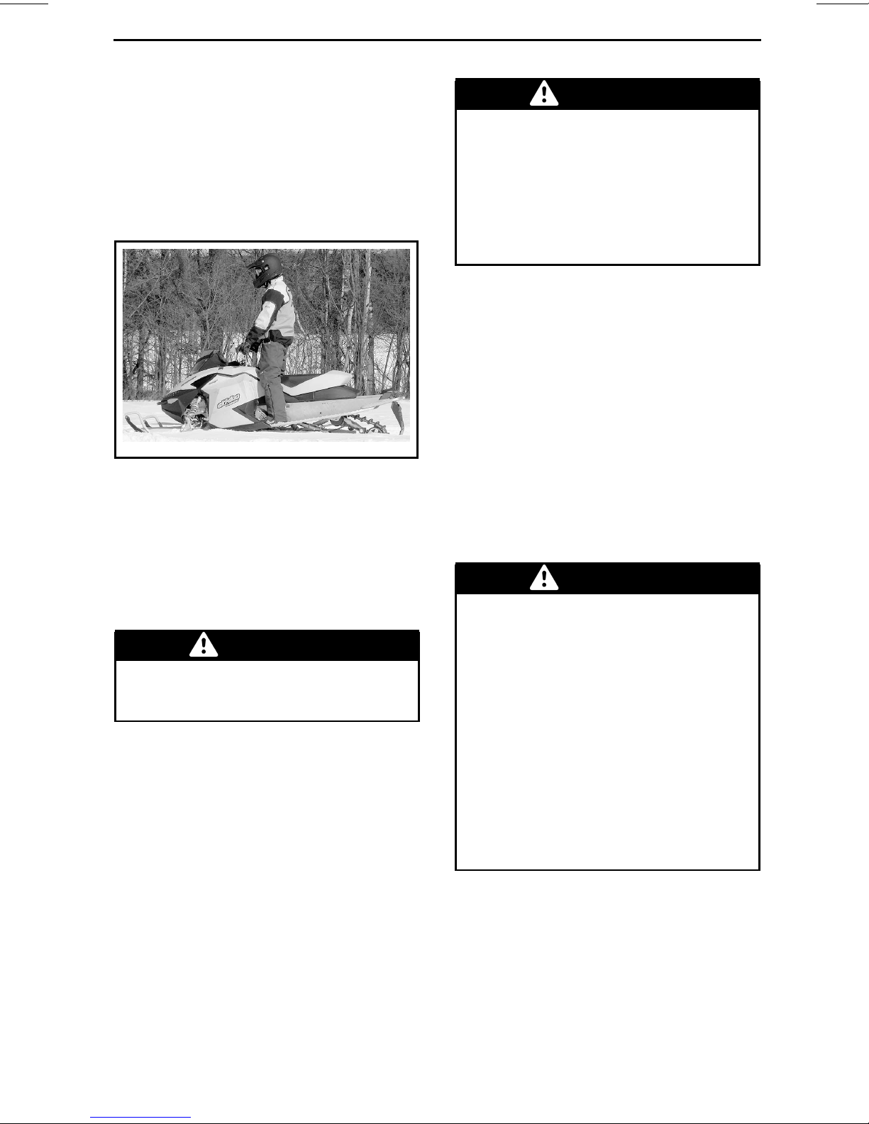
Standing
Place both feet on the running boards.
Knees should be flexed to absorb the
shock from surfa ce bump s. This is an
effective position to see better and
to shift weight as conditions dictate.
Avoid abrupt stop.
mmo2008-003-004
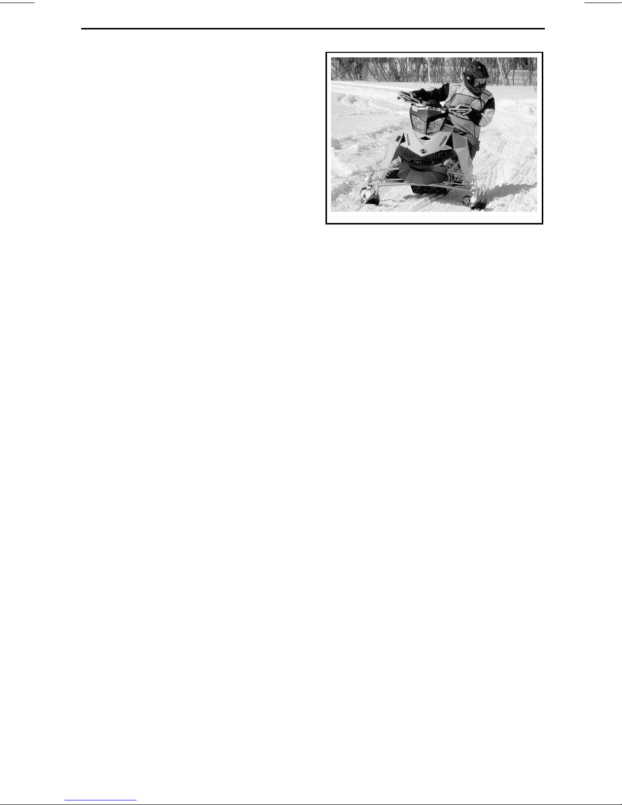
Rider Position (Reverse Operation)
We recommend sitting o n your snowmobile when operating in reverse.
Avoid standing up. Yo ur weight could
shift forward against throttle lever
while operating in reverse, causing
an unexpected acceleration.
WARNING
Unexpected acceleration when
snowmobile operates in reverse
can cause a loss of control.
Carrying a Passenger
Certain snowmobiles are designed
for an operator only (1-UP), and others
can allow one passenger (2-UP). Make
sure to identify and respect the warnings according to your specific model.
Even when a passenger is allowed,
this person m uch be physically fit for
snowmobiling.
WARNING
Any passenger must be able to
firmly lay his feet on the footrests
and keep his hands on the handholds or seat strap at all times
when seated. Respecting those
physical criteria is important to ensure that the passenger is stable
and to reduce the risks of ejection.
On snowmobiles allowing two passengers, if you have an adult and a child for
passenger, BRP recommends that the
child sits in the center location. This
allows an adult sitting in the rear seat
to keep a visual contact with the child
and hold him if n ecessary. In addition,
the child is best protected against the
wind and cold temperature if seated in
the center location.
The operator has a responsibility to ensure the safety of his passenger and
should inform the passenger about
snowmobiling basics.
WARNING
– Passenger must only sit on des-
ignated passenger seats. Never
allow anyone to sit between the
handlebar and the operator.
– Passenger and operators must
always w ear an approved helmets and warm clothing appropriate for snowmobiling. Make
sure that no skin is exposed.
– Once underway, if a passenger
feels uncomfortable or insecure
for any reason, he must right
away inform the operator to
slowdown or stop.
Riding with a passenger on b
ferent than riding alone. The operator
has the benefit of knowing what will
be the next maneuver an
prepare himself accordingly. The operator also benefits from the support of
his grip on the handl
the passenger has to rely on the oper-
ebar. In contrast,
oard is dif-
disableto
________
SAFETY INF
ORMATION
________
17
Page 20
RIDING THE VEHICLE
ator’s careful and safe operation of the
vehicle. In addition, “body english” is
limited with a passenger, and the operator can sometimes see more of the
trail ahead than the passenger. Therefore, smooth starting and stopping are
required with a passenger, and the operator must slow down. The operator
must also warn the passenger about
side hills, bumps, branches, etc. An
unforeseen bump can leave you passenger-less. Remind your passenger
to lean into the turn with you , with ou t
causing the vehic le to topple. Be extremely careful, go more slowly and
check the passenger frequently.
WARNING
When riding with a passenger:
– Braking ability and steering
control are reduced. Decrease
speed and allow extra space to
maneuver.
– Adjust suspension according to
weight.
For complete information on how to
adjust the suspension, please refer to
the
TUNE YOUR RIDE
Use e xtra caution and go even more
slowly with a young passenger. Check
frequentlyto make certain the childhas
a firm grip and is properly positioned
with his feet on the running boards.
Terrain/Riding Variations
Groomed Trail
On a maintained trail, sitting is the
most preferred riding position. Do not
race and, above all, keep to the right
hand side of the trail. Be prepared
for the unexpected. Observe all trail
signs. Do not zigzag from one side of
the trail to the other.
subsection.
Ungroomed Trail
Unless there has been a fresh snowfall you can expect “washboard” and
snowdrift conditions. Taken at excessive speeds, such conditions can be
physically harmful. Slow down. Hold
on the handlebar and assume a posting position. Feet should be under the
body assuming a crouched position to
absorb any jarring effect. On longer
stretches of “washboard” trails, the
kneeling position o f one knee on the
seat can be adopted. This provides a
certain amount of comfort, while at the
same time keeps the body loose and
capable of vehicle control. Beware of
hidden rocks or tree stumps partially
hidden by a recent snowfall.
Deep Snow
In deep “powder” snow, your vehicle
could begin to “bog” down. If this occurs,turninaswideanarcaspossible
and look for a firmer base. If you do get
“bogged”, and it happens to everyone,
do not spin your track as this makes the
vehicle sink deeper. Instead, turn the
engine off, get off and move the back
of the vehicle onto new snow. Then
tramp a clear path ahead of the vehicle. A few feet will generally suffice.
Restartthe engine. Assume the standing position and rock the vehicle gently
as you steadily and slowly apply the
throttle. Depending on whether the
front or rear end of the vehicle is sinking, your feet should be placed on the
opposing end of the running boards.
Never plac e foreign material beneath
the track for support. Do not al
one to stand in front of, or to the rear
of, the snowmobile with the engine
running. Stay away from the t
Personal injury will result if contact is
made with the revolving track.
low any-
rack.
18
_______
SAFETY I
NFORMATION
________
Page 21

RIDING THE VEHICLE
Frozen Water
Traveling frozen lakes and rivers can be
fatal. Avoid waterways. If you are in
an unfamiliar area, ask the local authorities or residents about the ice condition, inlets, outlets, springs, fast moving currents or other hazards. Never
attempt to operate your snowmobile
on ice that may be too weak to support you and the vehicle. Operating
a snowmobile on ice or icy surfaces
can be very dangerous if you do not
observe certain precautions. The very
nature of ice is foreign to good control of a snowmobile or any vehicle.
Traction for starting, turning or stop ping is much less than that on snow.
Thus, these distances can be multiplied manyfold. Steering is minimal,
and uncontrolled spins are an eve r
present danger. When operating on
ice, drive slowly with caution. Allow
yourself plenty of room for stopping
and turning. This is especially true at
night.
Hard Packed Snow
Don't underestimate hard packed
snow. It can be difficult to negotiate
as both skis and track do not have as
much traction. Best advice is to slow
down and avoid rapid acceleration,
turning or braking.
Uphill
There are two types of hills you can encounter - the open hill on which there
are few trees, cliffs or other obstacles,
and a hill that can only be climbed di
rectly. On an open hill, the approach is
to climb it by side hilling or slaloming.
Approachat an angle. Adopt a knee
position. Keep your weight on the uphill side at all times. Maintain a steady,
safe speed. Continue as far as y
in this direction, then switch to an opposite hill angle and riding position.
ling
ou can
A direct climb could present p rob lems.
Choose the standing position, accelerate before you start the climb and then
reduce throttle pressure to prevent
track slippage.
In either case, vehicle speed should be
as fast as the incline demands. Always
slow down as you reach the crest. If
you cannot proceed further, don't spin
your track. Turn the engine off, free the
skis by pulling them out and downhill,
place the rear of the snowmobile uphill
restart the engine and ease it out with
slow even throttle pressure. Position
yourself to avoid tipping over, then descend.
Downhill
Downhill driving requires that you have
full control of your v eh icle at all tim e s.
On steeper hills, keep your cen te r of
gravity low and both hands on the handlebar. Maintain slight throttle pressure and allow the machine to run
downhill with the engine operating.
If a higher than safe speed is reached,
slow down by braking but apply the
brake with frequent light pressure.
Never jam the brake and lock the track.
Side Hill
When crossing a s ide hill or traversing up or downhill, certain procedure s
must be followed. All riders should
lean towards the slope as required for
stability. The preferred operating positions are the kneeling position, with
thekneeofthedownhilllegonthe
-
seat and the foot of the uphill leg on
the running board, or the posting position. Be prepared to shift your weight
quickly as need ed. Side hills and
slopes are not recommended for a beginner or a novice snowmobiler.
Avalanche Hazard
When riding on mountainous te
you should be aware of the risk of
avalanches. Avalanches vary in size
and shapes and generally oc
steep terrain and on unstable snow.
steep
rrain,
cur in
________
SAFETY INF
ORMATION
________
19
Page 22

RIDING THE VEHICLE
New snow, animals, people, wind
and snowmobiles can all trigger
an avalanche. Avoid high marking
or traversing steep terrain when
avalanche conditions are possible.
When in unsta ble snow conditions,
travel should be restricted to lower
angle slopes. Wind formed cornices
should be avoided. Staying off unstable conditions is the key to safe
mountain riding. Probably most important is to be aware of the conditions
and dangers on a daily basis when in
the mountains. Check local avalanche
forecasts and threats each day before
heading out to ride and heed forecasters advice.
You shouldalwayscarry a snow shovel,
probe and avalanche beacon while riding on mountains. We recommend
that all mountain riders take a local avalanche safety training course
to become more familia r with snow
conditions and learn how to properly
use their equipment.
Here are some web sites that can help
you finding important information:
–US:www.avalanche.org
– Europe: www.avalanches.org
– Canada: www.avalanche.ca
Slush
Slush should be avoided at all times.
Always check for slush before starting
across any lake or river. If dark spots
appearinyourtracks,getofftheice
immediately. Ice and water can be
thrown rearward into the path of a following snowmobile. Getting a veh
out of a slush area is strenuous and in
some cases, impossible.
icle
Keep a safe distance behind other
snowmobilers to improve visibility and
reaction time.
Unfamiliar Territory
Whenever you enter an area that is
new to you, drive with extreme caution. Go slow enough to recognize
potential hazards such as fences or
fence posts, brooks crossing your
path, rocks, sudden dips, guy wires
and countless other obstacles w hich
could result in a termination of your
snowmobile ride. Even when following existing tracks, be cautious.
Travel at a speed so you can see what
is around the next bend or over the top
of the hill.
Bright Sunshine
Bright sunny days can considerably
reduce your vision. The glare from
sun and snow may blind you to the extent that you cannot easily distinguish
ravines, ditches or other obstacles.
Goggles with colored lenses should always be worn under these conditions.
Unseen Obstruction
There may be obstructions hidden
beneath the snow. Driving off established trails and in the woods requires reduced speed and increased
vigilance. Driving too fast in an area
can ma ke even minor obstacles very
hazardous. Even hitting a small rock
or stump could throw your snowmobile out of control and cause injury to
its riders. Stay on established trail
to reduce your exposure to hazards.
Be safe, slow down and enjoy the
scenery.
s
Fog or Whiteout Conditions
On land or water, fog or visibility-limiting snow can form . If you have
to proceed into the fog or heavy snow,
do so slowly with your light
watch intently for hazard s. If you are
not sure of your way, do not proceed.
20
_______
sonand
SAFETY I
Hidden Wires
Always be on the lookout for hidden
wires, especially in areas that m ay
have been farmed at one time or an
other. Too many accidents have been
caused by running into wires in the
fields, guy wires next to pole
NFORMATION
________
-
sand
Page 23
roads, and into chains and wires used
as road closures. Slow speeds are a
must.
Obstacles and Jumping
Unplanned jumps of snowdrifts, snowplow ridges, culverts or indistinguishable objects can be dangerous. You
can avoid them by wearing the proper
color lenses or face shields and by operating at a lower speed.
Jumpingasnowmobilecanbeahazardous situation. Be prepared before
landing to absorb the shock and brace
yourself for the impact. Knees must
be flexed to act as shock absorbers.
If the trail does suddenly drop away
from you, crouch (stand) towards the
rear of the vehicle and keep the skis up
and straight ahead. Apply partial throttle and brace yourself for the impact.
Knees must be flexed to act as shock
absorbers.
Tur ni ng
Depending on terrain conditions, there
are two preferred ways to turn or corner a snowmobile. For most snow
surfaces, “body english” is the key to
turning. Leaning towards the inside of
the turn and positioning body weight
on the inside foot will create a “banking” condition beneath the track. By
adopting this position a nd positioning
yourself as far forward as possible,
weight will be transferred to the inside
ski.
On occasion, you will find that the only
way to turn the vehicle about in deep
snow is to pull the snowmobile around.
Do not over-exert yourself. Get ass
tance. Remember to always lift using
your legs as opposed to your back.
is-
RIDING THE VEHICLE
mmo2008-003-005
Road Crossing
In some cases, you will be approaching the road from a ditch or snowbank.
Choose a place where you know you
can climb without difficulty. Use the
standing position and proceed with
only as much speed needed to crest
the bank. Stop completely at the top
of the bank and wait for all traffic to
clear. Judgethedroptotheroadway.
Cross the road at a 90° angle. If you encounter another snowbank on the opposite side, position your feet near the
rear of the vehicle. Remember, your
snowmobile is not designed to operate on bare pavement and steering on
this type of surface is more difficult.
Railroad Crossing
Never ride on railro ad tracks. It is illegal. Railroad tracks and railroad
rights-of-way are private property. A
snowmobile is no match for a train.
Before crossing a railroad track, stop,
look and listen.
Night Rides
The amount of natural and artificial
light at a given time can effect your
ability to see or to be seen. Nighttime
snowmobiling is delightful. It can be
a u nique experience if you acknowledge your reduced visib ility. Before
you start, make certain your lights
are clean and work properly. Drive
at speeds that will allow you to stop
in time when y ou see an unknown or
dangerous object ahead. Stay on es-
________
SAFETY INF
ORMATION
________
21
Page 24

RIDING THE VEHICLE
tablished trails and never operate in
unfamiliar territory. Avoid rivers and
lakes. Guy wires, barbed wire fences,
cabled road entrances and other objects such as tree limbs are difficult
to see at night. Never drive alone. Always carry a flashlight. Keep away
from residential areas and respect the
right of others to sleep.
Riding in a Group
Before starting out, designate a “trail
boss” to lead the party and another person to follow-upat the end of the party.
Ensure that all m em be rs of the party
are aware of the proposed route and
destination. Make certain that you are
carrying all necessary tools and equipment and that you have sufficient fuel
to complete the trip. Never overtake
the trail boss or, for that matter, any
other snowmobile. Use down-the-line
hand signals to indicate hazards or intent of direction change. Assist others
whenever necessary.
ItisalwaysIMPORTANTtokeepa
safe distance between each snowmobile. Always maintain a safe interval
and allow sufficient stopping distance.
Don't be a tailgater. Know the position
of the machine ahead.
Signals
Ifyouintendtostop,raiseeitherhand
straight above your head. A left turn is
indicated by extending your left hand
straight out in the proper direction. For
right turns, extend the left arm and
raise the hand to a vertical positio
forms a right angle at the elbow. Eve ry
snowmobiler should relay any signal to
the ones behind.
Trail Stops
Whenever possible, pull off the trail
when you stop. This will reduce the
hazard to other snowmobilers
the trail.
nsoit
using
Tr ails and Signs
Trail signs are used to control, direct or
regulate the use of snowmobiles on
trails. Become familiar with all signs
used in the area where you are snowmobiling.
Environment
Wildlife compliments your snowmobiling day. Snowmobile tracks provide
firm ground over which animals can
travel from area to area. Do not violate
this privilege by chasing or harassing
wildlife. Fatigue and exhaustion can
lead to animal's death. Avoid areas
posted for the protection or feeding of
wildlife.
If you happen to be fortunate enough
to see an animal, stop your snowmobile and observe quietly.
The guidelines that we support are not
designed to limit your snowmobiling
fun, but to preserve the beautiful freedom that you can experience only on
a snowmobile! These guidelines will
keep snowmobilers healthy,happy and
able to introduce others to what they
know and enjoy about their favorite
winter pastime. So, the next time you
hit the trails on a cool, crisp and clear
winter day, we ask you to remember
that you are paving the way for the future of our sport. Help us lead it down
the right path! From all of us at BR P,
thank you for doing your share.
There is nothing more exhilarating than
snowmobiling. Venturing onto snowmobile trails that cross wild areas is
an exciting and healthy winter sport.
However, as the number of people using these recreational parks incre
so does the potential for damage to the
environment. Abuse o f land, facilities
and resources inevitably leads t
strictions and closures of both private
and public land.
ases,
ore-
22
_______
SAFETY I
NFORMATION
________
Page 25

RIDING THE VEHICLE
In essence, the greatest th r eat to ou r
sport, is all around us. Which leaves
us with one logical choice. When we
snowmobile, we must alway s ride responsibly.
The vast majority respect the law and
the environment. Each of us must set
an example for those who are new to
the sport, young and old alike.
It is in every one's best interest to tread
lightly into our recreational areas. Because, in the long run, to protect the
sportwemustpreserve the environment.
Recognizing the importance of this issueandtheneedforsnowmobilersto
do their share in preserving areas that
make it possible to enjoy our sport,
BRP has developed the “Light Treading Is Smart Sledding” campaign for
snowmobilers.
Light Treading refers to more than the
thread of our tracks. It's a statement
of concern, respect and willingness
to take the lead and take action. It applies to the environment in general, its
proper care and maintenance, its natural inhabitants and all enthusiasts and
the public at large who enjoy the great
outdoors. With this theme, we invite
all snowmobilers to remember that respecting the environment is not only
critical to th e future of our industry but
to future generations.
Light Treading in no way suggests you
should curb your appetite for snowmobiling fun! It simply means tread wit
respect!
The fundamental objective of Light
Treading is one of respect for where
and how you ride a snowmo bile.
You're a light trea der when you fol
the principles below.
Become informed. Obta in maps,
ulations and other information from
the Forest Service or from other public land agencies. Learn th e
follow the m and that goes for speed
limits, too!
rules and
h
low
reg-
Avoid running over young trees,
shrubs, and grasses and don't cut
wood. On flatlands or areas where trail
riding is popular, it's important to ride
only where authorized. Rem em b e r,
there is a link between protecting your
environment and your own safety.
Respect wildlife andbeparticularly
sensitive of animals that are rearing
young or suffering from food shortage.
Stress can sap scarce energy reserves.
Refrainfromridinginareaswhereonly
animals are intended to tread!
Obey gate closures and regulatory
signs and remember, light treaders
don't litter!
Stay out of wilderness areas. They're
closed to all vehicles. K n ow where the
boundaries are.
Obtain permission to travel across
private land. Respect the rights of
landowners and other people's privacy. Remember, snowmobile technology has lowered the noise factor
considerably, but you still shouldn't rev
your engines where quiet “is the order
of the day”.
Snowmobilers know all too well the efforts that have been made throughout
the sport's history to enjoy access to
areas where people can snowmobile
safely and responsibly. This effort continues today, as strong as ever.
Respectingtheareaswhereweride...
wherever they may be... is the only
way to ensure their future enjoyment.
That's one major reason why we know
you'llagree that Light Treadingis smart
sledding! And there are more.
Enjoying the opportunity to see winter
and all its natural maje stic won ders
is an experience cherished by snowmobilers. Light Treading will preserve
this opportunity and will make
sible for us to expose others to the
beauty of winter and the unique thrill of
our sport! Light Treading wi
sport to grow!
it pos-
ll help our
,
________
SAFETY INF
ORMATION
________
23
Page 26

RIDING THE VEHICLE
Finally, Light Treading is the sign of a
smart snowmobiler. You don't have
to leave big tracks or careen t hrough a
virgin fores t to show you can ride. So
whether you're driving a high performance Ski-Doo, a sporty MX Z™ snowmobile or any other make or model,
show you know what you're doing.
Show you know how to send snow flying and ma ke tracks with a light touch!
24
_______
SAFETY I
NFORMATION
________
Page 27
TRACTION ENHANCING PRODUCTS
NOTE: This section is applicable to
snowmobiles equipped with a factory
installed track that has been approved
by BRP for special stu ds installation.
WARNING
Never stud a track that has not
been approved for studs. Installing studs on an unapproved
track could increase the risk of the
track tearing or severing.
WARNING
You may stud the track on this vehicle model. However, you MUST
only use the BRP approved type
stud for u se on these Ski-Doo
snowmobiles. DO NOT EVER
use conventional studs as the
track thickness is thinner then
other standard tracks. The stud
could tear off of track and separate
from vehicle. See an authorized
Ski-Doo dealer for current specific
studding availability and applications.
Using traction enhancing products
such as, more aggressive ski carbide
runners and/or studs on your snowmobile will change its behavior, particularly in terms of manoeuvrability,
acceleration, and braking.
Using traction enhancing products
gives a better grip on packed snow
and ice, but has no noticeable effect
on soft snow. For this reason, driving
a snowmobile equipped with traction
enhancing products requires a certain
adaptation period. If your snowmobile
is equipped with traction enhancing
products, be sure to take plenty of time
to get used to the way it handles when
turning, accelerating, and braking.
drive your snowmobile in a responsible
manner, respecting the environment
and other people’s property.
Manoeuvrability
Using traction enhancing products
such as, more aggressive ski carbide
runners and/or s tuds makes the snowmobile grip the ground better at both
the front and at the rear. The use of
carbide runners is therefore required
to give the skis a better grip, so that the
front and rear of the snowmobile are
in balance. While off-the-shelf carbide
ski runners are adequate, they don’t
necessarily giv e you optimal control,
since that depends on your personal
preferences,your riding style, and how
your suspension is adjusted.
WARNING
If the front and rear of the snowmobile are out of balance due to an
incorrect combination of traction
enhancing products, the snowmobile may tend to oversteer or
understeer, which could lead to a
loss of control.
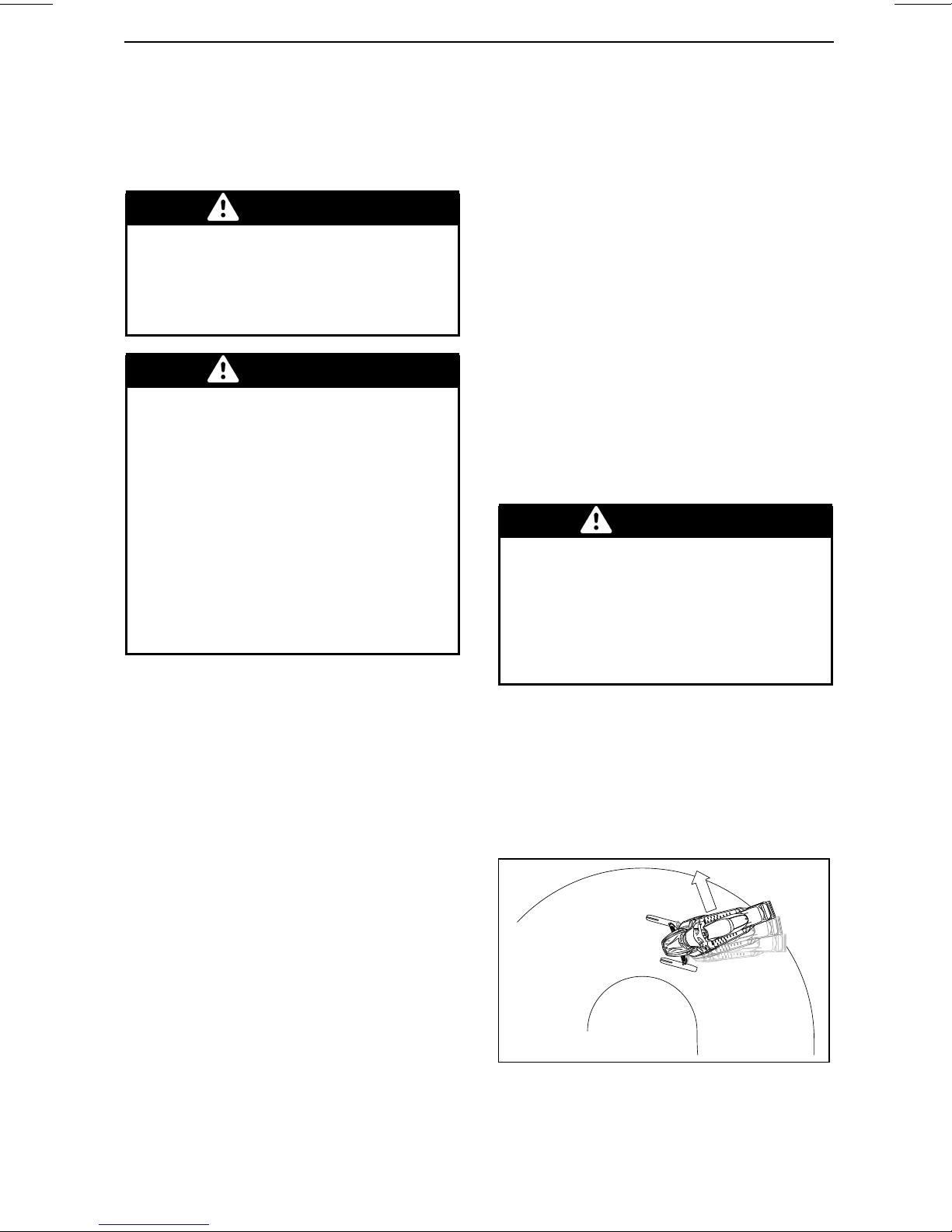
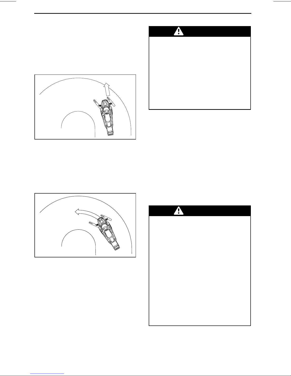
Oversteering
In certain conditions, using more aggressive ski carbide runners without
studs on the rear track could m ake the
snowmobile prone to oversteering,
see illustratio n.
Also, alwa ys check local regulations
concerning the use of traction enhancing products on sn owmobiles. Always
________
SAFETY INF
A33A31A
OVERSTEERING
ORMATION
________
25
Page 28
TRACTION ENHANCING PRODUCTS
Understeering
In certain conditions, the use of studs
onthetrackcouldmakethesnowmobile prone to understeering if the skis
are not equippedwith m ore aggressive
ski carbide runners, se e illustration.
A33A33A
UNDERSTEERING
Controlled Driving
A balanced combination of carbide ski
runners and studs on the track ensures
adequate control and better handling,
see illustratio n.
WARNING
To prevent surprises that could
lead to a loss of control of the
snowmobile:
– Always go e as y on the throttle.
– NEVER try to spin the track to
make the rear of the snowmo-
bile skid.
This could cause debris or ice to be
thrown violently backwards, possibly injuring others n earby or on
snowmobiles behind you.
Braking
As in the case of acceleration, using
studs on the track will give you better
braking capacity on packed snow or
ice but will have no noticeable effect
on soft snow. Braking may thus vary
suddenly under certain conditions.
Be sure to use restraint in braking to
keep from blocking the track in order to
avoid surprises that could lead to a loss
of control.
A33A34A
CONTROLLED DRIVING
Acceleration
Using studs on the track will allow your
sled to accelerate better on packed
snow and ice but will have no noticeable effect on soft snow. This can
cause sudden variations in traction
under certain conditions.
Important Safety Rules
WARNING
To prevent serious injury to individuals near the snowmobile:
– NEVER stand behind or near a
moving track.
– Always use a w ide-base s n ow -
mobile stand with a rear deflec-
tor panel if it is necessary to ro-
tate track.
– When the track is raised off the
ground, only run it at the lowest
possible speed.
Centrifugal force could cause debris, damaged or loose studs,
pieces of torn track, or an entire severed track to be violently
thrown backwards out of the t
nel with tremendous force.
un-
26
_______
SAFETY I
NFORMATION
________
Page 29
TRACTION ENHANCIN G PRODUCTS
Effects of Having a
Studded Track on the
Life of the Snowmobile
The use of traction enhancing products
can increase the load and the stress on
certain snowm obile components, as
well as the vibration level. This can
cause premature wear on parts such
as belts, brake linings, bearings, chain,
chaincase sprocket, and on approved
studded track s, shorten track life. Always proceed with a visual inspection of your track before each use. For
more information, refer to the
section in
MAINTENANCE
TRACK
.
Studs on the track ca n also cause serious damage to your snowmobile if
it is not equipped with the tunnel protectors designed for your particular
model. Damage to the electricalwiring
or perforation of the heat exchangers
are potential haza rds, that could cause
the engine to overheat and be severely
damaged.
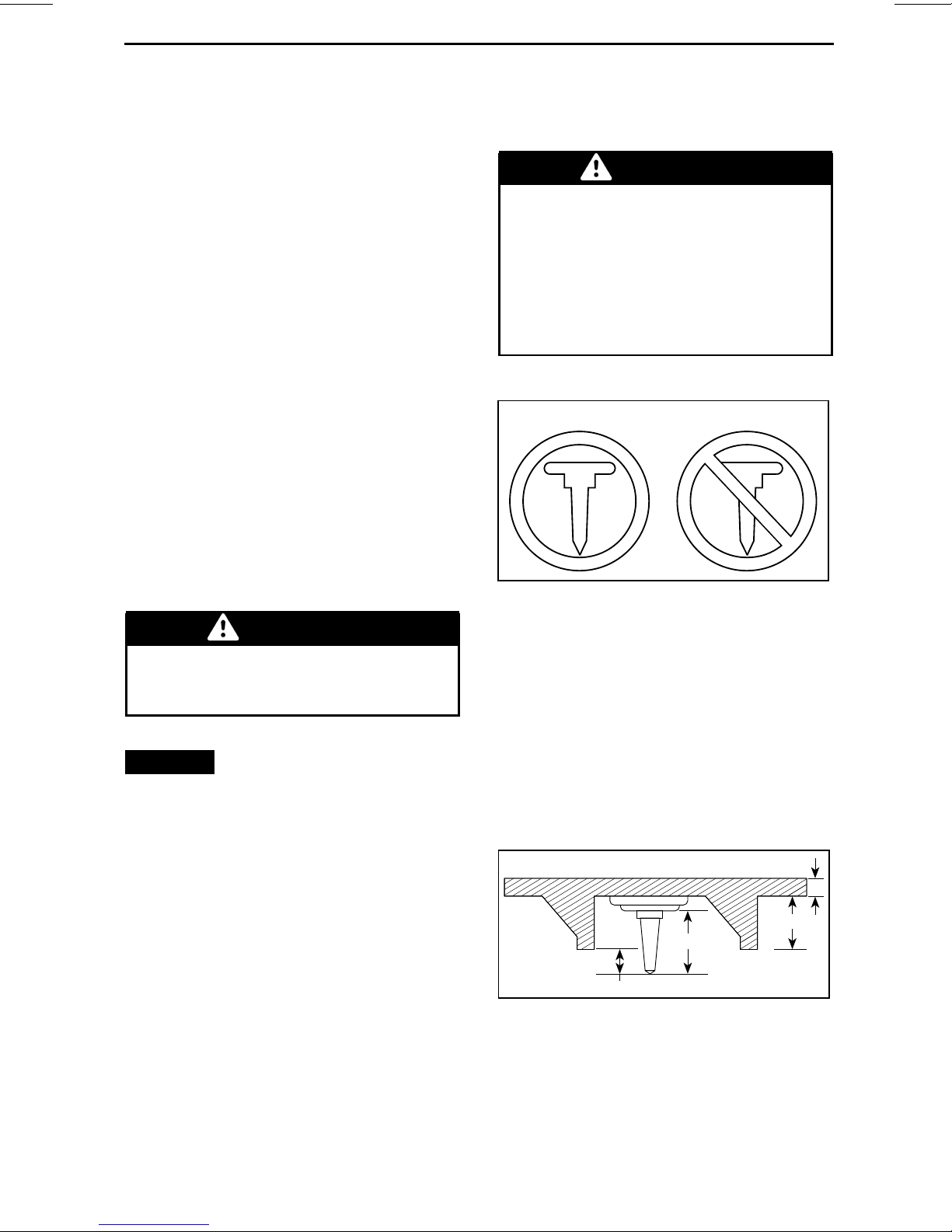
WARNING
Installation of Studs on
BRP Approved Tracks
WARNING
Never stud a track that has not
been approved for studs. Approved tracks can be identified by
a stud symbol (see illustration below) molded into the track surface.
Installing studs on an unapproved
track could increase the risk of the
track tearing or severing.
12
A00A8KA
TRACK SYMBOLS
1. Approved
2. NOT Approved
If tunnel protectors are excessively
worn or not installed, the gas tank
could be punctured, causing a fire.
NOTICE
Ask your dealer for the
appropriate tunnel protectors model
and kit number required for your
snowmobile.
NOTE: Consult the BRP limited war-
ranty to find out wha t warranty limitationsarerelatedtotheuseofstuds.
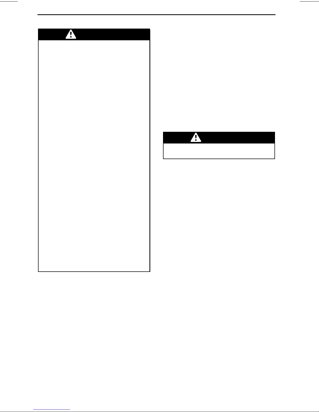
To ensure safe and proper installation,
BRP recommends to have the studs installed b y your dealer.
– Use only the BRP approved special
studs.
– Never use studs that exceed the
height of your snowmobile’s track
profile by more than 9.5 mm (3/8 in).
3
4
1
A33A32A
INSTALLATION OF STUDS
1. Stud size
2. Penetration range
6.4 mm to 9.5 mm (1/4 in to 3/8 in)
3. Track lug height
4. Track belt thickness
2
________
SAFETY INF
ORMATION
________
27
Page 30
TRACTION ENHANCING PRODUCTS
WARNING
– See an authorized Ski-Doo
dealer for current sp ecific studding availability and applications.
– DO NOT EVER use conventional
stud because, the track thickness is thinner then our standard tracks and the stud could
tear off of track and separate
from vehicle.
– Studs should only be installed
in the locations indicated by
molded bulges in the track surface.
– Never stud a track with a profile
of 35 mm (1.375 in) or more.
– The number of studs installed
must always perfectly match
the pattern of molded bulges in
the track.
– Always consult the traction
product manufacturer’s installation instructions and recommendations before having your
dealer install studs and runners.
It is very important to follow
the torque specifications for the
stud bolts.
INSTALLING AN INCORRECT
NUMBER OF STUDS OR AN IMPROPER INSTALLATION CAN INCREASE THE RISK OF THE TRACK
TEARING OR SEVERING.
– Broken studs (studded tracks)
– Bent studs (studded tracks)
– Missing studs
– Studs that are torn o ff the track
– Missing track guide(s)
– Loose studs.
On approved studded tracks, replace
brokenor damagedstuds immediately.
If y ou r track shows signs of deterioration, it must be replaced immediately.
When in doubt, ask your dealer. Always proceed with a visual inspection
of your track before each use.
WARNING
Riding with a damaged track or
studs could lead to loss of control.
Inspection
PROCEED WITH A VISUAL INSPECTION OF YOUR TRACK BEFOR E
EACH USE.
Look for any de f ects, such as:
– Perforations in the track
– Tears in the track (particularly
around traction holes on studded
tracks)
– Lugs that a re broken or torn off, ex-
posing portions of rods
– Delamination of the rubber
–Brokenrods
28
_______
SAFETY I
NFORMATION
________
Page 31

IMPORTANT ON PRODUCT LABELS
Hang Tag(s)
704901107
vmo2006-005-009_en
TYPICAL
Vehicle Safety Labels
The following labels are on your vehicle and they should be considered
permanent parts of the vehicle. If
missing or damaged, the decals can
be replaced free of charge. See an authorized Ski-Doo dealer.
NOTE: The following illustrations used
in this Operator's Guide are a general
representation only. Your model may
differ.
________
SAFETY INF
ORMATION
________
29
Page 32

IMPORTANT ON PRODUCT LABELS
6
5
2
15
1
14
mmo2010-007-003_h
12
mmo2011-003-004_b
13
1
16
7
4
30
_______
SAFETY I
NFORMATION
________
Page 33

IMPORTANT ON PRODUCT LABELS
4
mmo2015-007-007_b
TYPICAL - TUNDRA XTREME
16
2
13
1
14
12
7
1
15
mmo2014-007-001_a
mmo2010-007-004_c
mmo2008-003-069_f
mmo2011-003-006_c
________
SAFETY INF
ORMATION
________
31
Page 34

IMPORTANT ON PRODUCT LABELS
516005280
LABEL 1
DO NOT SIT HERE/
NE PAS SASSEOIR ICI
mmo2008-003-006_a
LABEL 2 - 1 UP MODELS
• NEVER stand behind
or near a rotating track.
Debris could be
projected causing
severe injuries.
• To remove packed
snow/ice, stop engine,
tilt and hold vehicle
on its side and use
wrench tool supplied
with vehicle
516006910
516006910
LABEL 3 - APPLICABLE MODELS
516006117
LABEL 4 - APPL ICABLE MODELS
516005587
LABEL 5
516 006 908
516006908
LABEL 6
516005509
LABEL 7
32
_______
SAFETY I
NFORMATION
________
Page 35

IMPORTANT ON PRODUCT LABELS
516005227
LABEL 8
________
SAFETY INF
516005228
LABEL 9
516005226
LABEL 10 - EUROPEAN MO
ORMATION
________
DELS
33
Page 36

IMPORTANT ON PRODUCT LABELS
AVERTISSEMENT
WARNING
516004568A
LABEL 11
516005511
LABEL 12
mmo2008-003-007
LABEL 15
Always electrically
disconnect
both fuel injectors
prior to testing for
ignition spark.
Otherwise, fuel
vapors may ignite
in presence of a
spark creating a
fire hazard.
516005583A
LABEL 13 - E-TEC ONLY
516005515
LABEL 14- E-TEC ONLY
5583A
mmo2008-008-023
LABEL 16 - ON BRAKE DISC GUARD (BARE
METAL TUNNEL)
AVERTISSEMENT
Ce garde doit TOUJOURS
être en place lorsque le
moteur fonctionne.
WARNING
This guard must
ALWAYS be in place
when engine
is running.
516005525
34
_______
SAFETY I
516005525
LABEL 16 - ON BRAKE DISC GUAR
(PAINTED TUNNEL)
NFORMATION
________
D
Page 37

This shock absorber is pressurized.
WARNING
An explosion may occur if heated
or punctured.
Do not disassemble.
mmo2010-003-101_en
LABEL 17 - ON SHOCK GAS CHARGED
ABSORBERS
IMPORTANT ON PRODUCT LABELS
mmo2013-004-046_a
LABEL18-ONFUELINJECTORS-E-TEC
MODELS
516005521
LABEL19-600ACE
________
SAFETY INF
ORMATION
________
35
Page 38

IMPORTANT ON PRODUCT LABELS
Compliance Labels
3
mmo2010-007-003_i
mmo2011-003-005_f
1
36
_______
SAFETY I
NFORMATION
________
Page 39

IMPORTANT ON PRODUCT LABELS
EPA Compliance Label
EMISSION CONTROL INFORMATION
THIS VEHICLE IS CERTIFIED TO OPERATE ON
UNLEADED GASOLINE AND MEETS XXXX U.S.
EPA REGULATIONS FOR SNOWMOBILE SI ENGINES.
ENGINE FAMILY
PERMEATION FAMILY
ENGINE DISPLACEMENT
EXHAUST EMISSION
CONTROL SYSTEM
RENSEIGNEMENTS SUR LE DISPOSITIF ANTIPOLLUTION
CE VÉHICULE EST CERTIFIÉ POUR FONCTIONNER À
L'ESSENCE SANS PLOMB ET IL RÉPOND AUX NORMES XXXX
DE L'EPA DES É.-U. POUR LES MOTONEIGES À MOTEUR SI.
SEE OPERATORS GUIDE FOR MAINTENANCE SPECIFICATIONS
VOIR GUIDE DU CONDUCTEUR POUR LES SPÉCIFICATIONS DENTRETIENS
BOMBARDIER RECREATIONAL PRODUCTS INC.
516005052
XXXXX.XXXXXX
XXXXXXXXXXXX
XX g/kW-hr HC
FEL
XXX g/k
W-hr CO
XXX.X cm
XXX
COMPLIANCE LABEL 1 - IN ENGINE
COMPARTMENT
FAMILLE DE MOTEUR
FAMILLE DE PERMÉATION
LIMITE DES ÉMISSIONS
DE LA FAMILLE
3
CYLINDRÉE
SYSTÈME DE CONTRÔLE
DES ÉMISSIONS
Technical Information
Labels
516 005 052
mmo2011-003-006_b
516006562
LABEL2-600ACEMODELS
SSCC Label
Safety standards for snowmobiles
have been adopted by the Snowmobile Safety and Certificatio n Committee (SSCC) of which BRP is a proud
participating member. Assurance that
your snowmobile meets these standards is easily checked by locating the
Certification L abel on a right vertical
portion of the vehicle.
The following la bel shows that an independent testing laboratory has verified
compliance with the SSCC safety standards.
PRINTED IN U.S.A.
CERTIFIED
CERTIFIÉ
THIS MODEL HAS BEEN
EVALUATED BY AN INDEPENDENT TESTING LABORATORY AND IT MEETS ALL
SSCC SAFETY STANDARDS
IN EFFECT ON THE DATE OF
ITS MANUFACTURE.
SPONSORED BY THE SNOWMOBILE SAFETY AND CERTIFICATION COMMITTEE, INC.
CE MODÈLE A ÉTÉ ÉVALUÉ
PAR UN LABORATOIRE
D'ESSAIS INDÉPENDANT
ET SATISFAIT TOUTES LES
NORMES DE SÉCURITÉ DU
SSCC EN VIGUEUR À LA
DATE DE FABRICATION.
PARRAINÉ PAR LE COMITÉ DE
SÉCURITÉ DE CERTIFICATION
DE LA MOTONEIGE, INC.
A00A1MA
LABEL 3
mmo2011-003-005_c
The engine of this snowmobile has been developed and
validated using the BRP XPS
BRP strongly recommends the
use of its XPS
TM
approved lubricant at all times.
TM
approved lubricant.
Damages caused by oil which is not suitable for the
engine will not be covered by the BRP limited warranty.
516006689
LABEL 1
516005876
LABEL 2
________
SAFETY INF
ORMATION
________
37
Page 40

IMPORTANT ON PRODUCT LABELS
A
V
I
S
N
O
T
I
C
E
A
V
I
S
N
O
T
I
C
E
A
V
I
S
N
O
T
I
C
E
A
V
I
S
N
O
T
I
C
E
516005503
LABEL 3
A
N
H
T
O
E
L
F
I
OCTANE
87
S
I
M
B
L
E
N
D
(
M
A
X
1
0
%
)
-
)
%
0
1
X
A
M
(
L
O
N
A
H
T
É
E
G
N
A
É
L
mmo2013-002-003
1
9
E
S
U
-
-
A
-
U
T
I
L
I
S
E
R
D
U
9
1
LOCATED ON FUEL CAP - ON 550F AND
600 ACE ENGINES (IN COUN TRIE S USING
PUMP POSTED AKI (RON+MON)/2 OCTANE
RATINGS)
%
0
E
1
T
H
X
OCTANE
A
N
O
L
B
L
E
N
D
A
M
-
%
0
E
1
T
H
X
mmo2013-002-004
A
M
-
A
-
M
É
L
A
N
G
OCTANE
95
E
É
A
N
O
L
B
L
E
N
D
%
0
1
X
A
M
L
O
N
A
H
T
LOCATEDONFUELCAP-ON600HO
E-TEC ENGINE (IN COUNTRIES USING RON
OCTANE RATINGS)
A
mmo2013-002-002
91
%
-
M
É
L
A
N
G
E
A
É
H
T
0
1
X
A
M
L
O
N
LOCATEDONFUELCAP-ON600HO
E-TEC ENGINE (IN COUNTRIES USING
PUMP POSTED AKI (RON+MON)/2 OCTANE
RATINGS)
A
N
H
T
O
E
L
F
B
I
mmo2013-002-005
5
9
E
S
U
-
-
A
-
U
T
I
L
OCTANE
92
I
S
E
R
D
U
9
5
S
L
E
N
D
(
M
A
X
1
0
%
)
-
)
%
0
1
X
A
M
(
L
O
N
A
H
T
É
E
G
I
M
N
A
É
L
LOCATED ON FUEL CAP - ON 5 50F AND 600
ACE ENGINES (IN COUNTRIES USING RON
OCTANE RATINGS)
38
_______
SAFETY I
NFORMATION
________
Page 41

VEHICLE
INFORMATION
_______________
39
Page 42

CONTROLS, INSTRUMENTS A ND EQUIPMENT
NOTE: Some features m ay not apply to your model or could be optional.
15
10
19
11
12
13
24
1
18
23
15
mmo2010-007-003_j
TYPICAL - TUNDRA SPORT 1-UP
15
mmo2015-007-007_a
TYPICAL - TUNDRA XTREME
10
11
12
13
18
1
23
15
24
40
______________
Page 43

mmo2013-007-001_b
2-UP
5
CONTROLS, INSTRUMENTS AND EQUIPMENT
16
7
4
3
9
mmo2010-007-008_c
TYPICAL - 550F MODELS
8
2
6
_______________
41
Page 44

CONTROLS, INSTRUMENTS AND E QUIPMENT
17
4
3
mmo2015-007-006_a
TYPICAL
5
9
6
2
mmo2011-003-005_g
TYPICAL
42
______________
mmo2008-003-069_p
TUNDRA LT
1) Handlebar
The handlebar controls the steering
of the snowmobile. As the handlebar
is rotated to right or left, the skis are
turned right or left to steer the snowmobile.
Page 45

WARNING
Fast reverse while turning, could
result in loss of stability and control.
2) Throttle Lever
Throttle lever is located on the RH side
of ha ndlebar.
CONTROLS, INSTRUMENTS AND EQUIPMENT
Designed to be thumb activated.
When squeezed, it increases the engine speed. When released, engine
speed returns automatically to idle.
(All Except 600 ACE)
mmo2008-008-011_b
TYPICAL
1. Throttle lever
2. To accelerate
3. To decelerate
WARNING
Test the throttle lever operation
each time before starting the engine. The lever must return to the
rest position once released. Otherwise, do not start engine.
mmo2015-008-103_a
TYPICAL
WARNING
Test the throttle lever operation
each time before starting the engine. The lever must return to its
the rest position once released.
Otherwise, do not start engine.
Switching from Thumb to Finger
Throttle Position
CAUTION It is highly recommended to immobilize the snowmobile before attempting any modification to the throttle position as it
could lead to a hazardous situation.
There are mainly three positions to
choose from when going from the
thumb to the finger throttle position
and the best on e will be to the rider's
preference and in direct relation with
the riding style and conditions.
Throttle Lever (600 ACE)
Throttle lever is located on the RH side
of ha ndlebar.
Designed to be either thumb activated
or finger activated. When squeezed, it
increases the engine speed. When
leased, engine speed return s automatically to idle.
re-
mmo2015-008-102_a
THUMB THROTTLE POSITION : PUSH
DOWNWARD TO ROTATE THROTTLE
HOUSING
_______________
43
Page 46

CONTROLS, INSTRUMENTS AND E QUIPMENT
mmo2015-008-100_a
IF WANTED, CONTINUE TO ROTATE THE
THROTTLE HO USING
mmo2015-007-004_a
TYPICAL
1. Brake lever
2. To apply brake
4) Parking Brake Lever
Parking brake leve r is located on the LH
side of handlebar.
mmo2015-008-101
FINGER TH RO TTLE POSITION
CAUTION
– It is HIGHLY recommended to use
gloves and NOT mitts when using
the finger throttle position.
– It is not recommended to use the
finger throttle position while riding in dense off trail areas.
The procedure to go back to the thumb
throttle position is the reverse of the
one shown above.
3) Brake Lever
Brake lever is located on the LH side of
handlebar.
When squeezed, brake is applied.
When released, it automatically returns to the rest position. Braking effect is proportional to the pressure
appliedontheleverandtothetypeof
terrain and its snow coverage.
Parking brake should be used whenever snowmobile is parked.
mmo2015-007-004_b
TYPICAL
1. Parking brake lever
WARNING
Make sure parking brake is fully
disengaged before operating the
snowmobile. When you ride the
vehicle, brake pads that are caused
to drag by a continuous pressure
on the lever may cause damage to
the brake system and cause loss of
braking capacity and/or fire.
44
______________
Page 47

CONTROLS, INSTRUMENTS AND EQUIPMENT
To Engage Parking Brake
Apply and hold brake, then lock brake
lever using the parking brake lever as
shown.
mmo2015-007-004_c
TYPICAL — ENGAGE MECHANISM
Step 1: Apply and hold brake
Step 2: Lock brake lever using parking brake
lever
WARNING
Always attach tether cord eyelet
to clothing before starting the engine.
All Models Except 550F
After engine starting, 2 short beeps
should be heard if a programmed
D.E.S.S. key (tether cord cap) is correctly snapped on engine cut-off
switch. If another beep code is heard,
refer to
D.E.S.S. malfunction codes information.
D.E.S.S. (Digitally Encoded Security
System)
All Models Except 550F
D.E.S.S. stands for Digitally Encoded
Security System.
MONITORING SYSTEM
for
To Release Parking Brake
Squeeze brake lever. Parking brake
lever will automatically return to its
original position.
Always release parking brake before
riding.
WARNING
Make sure parking brake is released before operating the vehicle. If parking brake is left ON
while riding, it may cause damage
to the brake system and cause loss
of braking capacity and/or fire.
5) Engine Cut-Off Switch
The engine cut-off switch (tether cord)
is located to on the LH side of console.
The tether cord cap must be securely
snapped on the engine cut-off switch
to allow vehicle operation.
Pulling the tether cord cap from the
switch shuts the engine off.
The tether cord cap contains an electronic chip which features a unique
permanently memorized digital code.
Your authorized Ski-Doo dealer h as programed the D.E.S.S. of your snowmobile to recognize the D.E.S.S. key in the
tether cord cap to allow vehicle operation.
If another tether cord is used without
programming the D.E.S.S., the engine
will start but will not reach drive pulley
engagement speed to move vehicle.
D.E.S.S. Flexibility
The D.E.S.S. of your snowmobile can
be programmed by your authorized
Ski-Doodealertoacceptupto8different keys.
We recommend the purchase of additional tether cords from your authorized Ski-Doo dealer. If you have
more than one D.E.S.S. equipped
Ski-Doo snowmobile, each can be programmed by your authorized Ski-Doo
dealer to accept the other vehicles
D.E.S.S. keys.
_______________
45
Page 48

CONTROLS, INSTRUMENTS AND E QUIPMENT
RF D.E.S.S. Key Types (600 ACE)
Two types of keys can be used:
–Normalkey
– Learning key.
To ease key type recognition, the key
comes in different colors.
KEY TYPE COLOR
Normal Black
Learning
The Ski-Doo learning key, limits the
speed of the snowmobile and the engine torque, therefore enabling first
time users and less experienced operators to learn how to operate the
snowmobile while gaining the necessary confidence and control.
NOTE: The initial learning key programming can limit the speed
to 40 km/h (25 MPH) or 70 km/h
(43 MPH). Refer to your authorized
Ski-Doo dealer to modify this setting.
Refer to
tion for details.
OPERATING MODES
Green
subsec-
6) Emergency Engine
Stop Switch
The emergency engine s top switch is
located on the RH side of handlebar.
To allow engine starting, the switc h
must be in the ON positio n (UP).
mmo2007-009-038_b
ON POSITION
All operators of the snowmobile
should familiarize themse lve s with the
function of the emergency engine stop
switch by using it several times on first
outing and whenever stopping the engine thereafter. This engine stopping
procedure will become a reflex and will
prepare operators for emergency situations requiring its use.
WARNING
If the switch has been used in an
emergency caused by a suspected
malfunction, the source of the malfunction should be determined
and corrected before restarting
engine. See an authorized Ski-Doo
dealer for servicing.
Use the emergency stop switch to
stop engine in a e mergency situation.
To stop the engine, push switch down
(OFF position).
mmo2007-009-038_a
OFF POSITION
46
______________
7) Ignition Switch (550F)
Ignition switch is located on the RH
side of gauge support.
Page 49

mmo2010-004-002_a
TYPICAL
1. OFF
2. ON
3. START
Tu rn key to ON position to allow manual engin e starting.
On electric start models, turn key to
START position to engage starter.
CONTROLS, INSTRUMENTS AND EQUIPMENT
9) Multifunction Switch
(Sport, LT and Extreme)
Multifunction switch is locate d o n the
LH side of handlebar.
mmo2015-007-003_a
1. Headlights dimmer switch
2. Heated grips switch
3. Heated throttle lever switch
4. Electronic reverse button
Refer to
DURE
ENGINE STARTING PROCE-
in the
BASIC PROCEDURES
section for detailed sta rting procedure.
8) Choke Lever (550F)
The choke lever has 3-positions.
1
2
A06H1KA
1. OFF
2. Position 2
3. Position 3
Refer to
BASIC PROCEDURES
structions on choke use.
3
CHOKE APPLICATION
section for in-
in the
Electronic Reverse/Start Button
600 ACE and 600 HO E-TEC Models
Press to engage electric starter.
Refer to
DURE
ENGINE STARTING PROCE-
in the
BASIC PROCEDURES
section for detailed sta rting procedure.
550F and 600 HO E-TEC M odels
With engine running, press to engage
the electronic reverse. Refer to
VERSE (RER™)
DURES
section for procedure.
in
BASIC PROCE-
Headlights Dimmer Switch
Press to select HI or LOW beam.
Lights are automatically ON when the
engine is running.
Heated Grips Switch
NOTE: On 600 ACE and E-TEC models, the heated grips are e nabled above
2000 RPM.
RE-
Select the switch position according to
the desired heating intensity to keep
your hands at a comfortable temperature.
_______________
47
Page 50

CONTROLS, INSTRUMENTS AND E QUIPMENT
mmo2015-007-003_b
TYPICAL
1. Heated grip switch
2. Hot
3. Warm
4. Off
10) Shift Lever (600 ACE)
Use this lever to shift in forward or reverse.
Heated Throttle Lever Switch
NOTE: On 600 ACE and E-TEC models, the heated throttle lever is enabled
above 2000 RPM.
Select the switch position according to
the desired heating intensity to keep
your thumb at a comfortable temperature.
mmo2015-007-003_c
TYPICAL
1. Heated throttle lever switch
2. Hot
3. Warm
4. Off
mmo2009-005-015_a
1. Reverse shift lever
mmo2009-005-016_a
PULL TO ENGAGE REVERSE GEAR
Refer to
BASIC PROCEDUR ES
OPERATING IN REVERSE
for details.
in
11) Rewind Starter Handle
Auto-rewind type located on right hand
side of snowmobile. To engage mechanism, pull handle slowly until a resistance is felt then pull vigorously.
Slowly release handle.
48
______________
12) Operator's Guide
1-UP Models
Underneath the seat.
Page 51

mmo2007-009-071_b
TYPICAL - SEAT
1. Operator's Guide location
2-UP Models
In the seat storage compartment.
Seat Latch (1-UP Only)
Use to remove seat to access the Op erator's Guide or for maintenance purposes.
CONTROLS, INSTRUMENTS AND EQUIPMENT
mmo2007-009-072_a
1. Seat latch
Pull and hold seat latch, then, pull seat
with a rearward m ovement.
Seat latch is located at the front of the
seat.
mmo2007-009-071_a
SEAT BASE
1. Seat latch
2. Operator's Guide location
13) Seat
Seat Removal
To remove seat, pull front of seat cushion, firmly push seat forward to unload
latch, then pull tab to unlock seat.
mmo2007-009-073_c
TYPICAL
Step 1: Push seat forward
Step 2: Pull and hold seat l atch
Step 3: Pull seat rearward
Seat Installation
NOTICE
Riding the vehicle with
any objects between the seat and
the fuel tank could damage the fuel
tank. NEVER place any objects between seat and fuel tank.
Position seat in place.
Push seat forward until it latch in it
spo-
sition.
_______________
49
Page 52

CONTROLS, INSTRUMENTS AND E QUIPMENT
mmo2007-009-073_b
TYPICAL
Step 1: Position seat in place
Step 2: Push seat forward until it latch
To remove the tool kit support from the
pulley guard, unlock the tab from underneath the pulley guard and pull the
tool kit support upwards to release it.
NOTE: A distinctiv e snap will be felt.
Double check that the seat is secure by
giving it a tug to confirm proper latching.
mmo2007-009-074
TYPICAL - SEAT INSTALLED
WARNING
Make sure seat is securely latched
before riding.
mmo2011-003-001_a
TYPICAL
1. Tool kit
15) Front and Rear
Bumpers
To be used whenever snowmobile requires manual lifting.
CAUTION Use proper lifting
techniques, notably using your legs
force. Do not attempt to lift either
end of the vehicle if it is above your
limits. Use appropriate lifting device or have assistance to share lifting stress if possible.
14) Tool Kit
A tool kit containing tools for basic
maintenance is supplied with the vehicle.
The tool kit support is located in engine
compartment on pulley guard.
NOTICE
cured properly to avoid contact with
CVT (continuously variable transmission).
50
______________
Make sure tool kit is se-
mmo2010-007-010_a
FRONT
1. Front bumper
Page 53

mmo2015-007-001_a
TYPICAL - REAR
1. Rear bumper
CONTROLS, INSTRUMENTS AND EQUIPMENT
NOTICE
Do not use skis to pull or
lift snowmobile.
16) Gauge (550F)
WARNING
Reading the gauge digital display
can distract from the operation of
the vehicle, particularly from constantly scanning the environment.
Gauge Description
mmo2010-004-004
LH PORTION OF GAUGE
2) Tachometer (RPM)
Measures engine revolution per
minute (RPM). Multiply by 1000 to obtain the actual revolutions.
mmo2011-002-001_c
1. Speedometer
2. Tachometer
3. Digital display
4. Pilot lamps
NOTE: The gauge is factory preset
in Imperial units but it is possible to
change it to metric units, contact an
authorized Ski-Doo dealer for unit settings.
1) Speedometer
Measures vehicle speed (in miles per
hour or kilometers per hour depending
on the setting).
mmo2011-002-002
RH PORTION OF GAUGE
3) Digital Displ ay
mmo2008-003-013_h
1. Digital display
_______________
51
Page 54

CONTROLS, INSTRUMENTS AND E QUIPMENT
The multifunction display is used to:
– Display the WELCOME message
on power up
– Display the KEY recognition mes-
sage
– Provide various indications as se-
lected by the operator
– Activating or changing various func-
tions or modes of operation
– Display scrolling messages of func-
tion activation or system faults
– Display fault codes.
4) Pilot Lamps and Messages
PILOT
LAMP(S)ONBEEPER DESCRIPTION
Injection oil level is
low. Stop vehicle
—
—
Long
beeps
repeating
slowly
—
in a safe place then,
replenish injection
oil reservoir.
Low fuel level.
Replenish fuel
tank as soon as
possible.
Reverse is
selected.
High beam
headlights are
selected.
Gauge Features
mmo2011-002-002_a
1. Pilot lamps
See table below for pilot lamps information.
AVAILABLE INDICATIONS IN
DIGITAL DISPLAY
FUNCTIONS
A) Odometer
B) Fuel level X
X = An X indicates a standard feature
550F
X
A) Odometer
Records the total distance t ravelled (in
miles or kilometers depending on the
setting).
The odometer is displayed on the digital display.
B) Fuel Level
Bar gauge that continuously indicates
the amount of fuel left in the fuel tank.
Displayed on the digital display.
52
______________
Page 55

mmo2008-003-020_a
FUEL LEVEL
1. Operating range
17) Gauge (600 ACE and
600 HO E-TEC)
CONTROLS, INSTRUMENTS AND EQUIPMENT
mmo2008-003-014
LH PORTION OF GAUGE
2) Tachometer (RPM)
WARNING
Reading the gauge digital display
can distract from the operation of
the vehicle, particularly from constantly scanning the environment.
Gauge Description
mmo2008-003-013_g
ANALOG/DIGITAL GAUGE (STANDARD)
1. Speedometer
2. Tachometer (RP M)
3. Gauge digital display
4. Gauge pilot lamps
5. Gauge SET (S) button
Measures engine revolution per
minute (RPM). Multiply by 1000 to obtain the actual revolutions.
mmo2008-003-019
RH PORTION OF GAUGE
3) Digital Displ ay
NOTE: The gauge is factory preset
in Imperial units but it is possibl
change it to metric units, contact an
authorized Ski-Doo dealer for unit settings.
1) Speedometer
Measures vehicle speed (in miles per
hourorkilometersperhourd
on the setting).
eto
mmo2008-003-013_h
1. Digital display
epending
_______________
53
Page 56

CONTROLS, INSTRUMENTS AND E QUIPMENT
The multifunction display is used to:
– Display the WELCOME message
on power up
– Display the KEY recognition mes-
sage
– Provide various indications as se-
lected by the operator
– Activating or changing various func-
tions or modes of operation
– Display scrolling messages of func-
tion activation or system faults
– Display fault codes.
WARNING
Never adjust or set functions on
the multifunction gauge while riding the vehicl e.
PILOT
LAMP(S) ON
BEEPER DESCRIPTION
Two stroke engine: Injection oil level is low. Stop
vehicle in a safe place then, replenish injection oil
4short
beeps every
5minutes
reservoir.
Four stroke engine: Low engine oil pressure. Stop
vehicle in a safe place then, check oil level. Fill to
proper level. If oil level was correct, discontinue use
and contact an authorized Ski-Doo dealer.
4) Pilot Lamps and Messages
mmo2008-003-024_a
TYPICAL — PILOT LAMPS
See table below for usual pilot lamps
information. Refer to
SYSTEM
for details on malfunction pi-
MONITORING
lot lamps.
—
Long beeps
repeating slowly
3 short beeps Reverse did not engage, try again.
—
Low fuel level. One (1) bar left in fuel le v el display.
Replenish fuel tank as soon as possible.
Reverse is selected.
High beam headlights are selected.
5) SET (S) Button
Button used to navigate, adjust or reset gauge multifunction display.
In order to memorize settings, eng ine
must be running.
NOTE: SET(S)buttononthemultifunction switch has the same functions and can also be used.
54
______________
Page 57

Gauge Features
CONTROLS, INSTRUMENTS AND EQUIPMENT
AVAILABLE INDICATIONS IN DIGITAL D ISP LAY
FUNCTIONS
A) Odometer
B) Trip meter “A” or “B” N.A. X X
C) Trip hour meter
D) Fuel level X X X
E) E-TEC engine storage mode
X = An X indicates a standard feature
N.A. = Not Available
550F 600 HO E-TEC 600 ACE
XXX
N.A. X X
N.A. X N.A.
A) Odometer
Records the total distance travelled.
Press the SET (S) button to select
odometer mode.
mmo2008-003-013_c
1. Trip meter (TRIP A/TRIP B) mode
mmo2008-003-013_c
1. Odometer mode
B) Trip Meter “A” or “B”
Trip meters records distance travelled
since it has been res et.
Press the SET (S) button to select trip
meter (TRIP A/TRIP B) mode.
Press and hold the SET (S) button to reset.
mmo2008-003-013_d
C) Trip Hour Meter
Records vehicle running time when
the electrical system is activated since
it has been reset.
Press the SET (S) button to select trip
hour meter (HrTRIP) mode.
_______________
55
Page 58

CONTROLS, INSTRUMENTS AND E QUIPMENT
mmo2008-003-013_c
1. Trip hour meter (H rTRIP) mode
WARNING
This strap is not for towing, lifting
or other purpose than temporary
use as a grab handle when a leverage is needed at very low speeds.
19) Rear Rack (All Models
Except Tundra
Extreme)
Press and hold the SET (S) button to reset.
mmo2008-003-013_d
D) Fuel Level
Bar gauge that continuously indicates
the amount of fuel left in the fuel tank.
WARNING
All objects in rear rack must be
properly latched. Do not carry
any breakable objects. Excessive
weight in rack may reduce steering ability. Always readjus t suspension according to the load.
The capacity of this rack is limited, the MAXIMUM cargo load
is 25 kg (55 lb). Ride at very low
speed when loaded. Avoid speed
over bumps.
20) Hitch
Tundra LT
Use the hitch in conjunction with a tow
bar to tow an accessory.
NOTE: Refer to decal on vehicle for
towing weight capacities.
mmo2008-003-020_a
FUEL LEVEL
1. Operating range
E) E-TEC Engine Storage Mode
Displays OIL when the storage mode
procedure is initiated.
18) Mountain Strap
Usethemountainstraptohelpw
transfer when riding at low speed.
56
______________
WARNING
Never tow an accessory with a
rope. Always use a rigid t ow bar.
Usingaropewouldresultinacollision between the object and the
snowmobile and possibly in a tip
over in case of a rapid deceleration
or on a downward slope.
Hitch (Tongue Type)
To attach an equipment tothe hitch, secure the accessory tow bar to the hitch
tongue using a lockable pin.
eight
Page 59

mmo2011-002-100_b
HITCH (TONGUE TYPE)
1. Tongue
Hitch (C Type)
To attach an equipment to the hitch:
Detach hitch from its support by re-
moving the hairpin.
CONTROLS, INSTRUMENTS AND EQUIPMENT
Secure rod to hitch using hairpin previously removed.
mmo2008-003-072_a
TYPICAL
1. Hairpin
2. Rod
mmo2008-003-070_a
HITCH (C TYPE)
1. Hitch
2. Hairpin
Remove rod from hitch th en attach
rigid tow bar to hitch using the same
rod.
NOTICE
To avoid damages to the
vehicle, always release hitch from its
support. Ensure hitch moves freely
when towing an accessory.
mmo2008-003-073_a
HITCH MOVES FREELY WHEN TOWING
To avoid noise from hitch when not in
use, secure hitch to its support by u
s-
ing the hairpin.
mmo2008-003-071_a
TYPICAL
1. Rod
_______________
57
Page 60

CONTROLS, INSTRUMENTS AND E QUIPMENT
mmo2008-003-074_a
HITCH NOT IN USE
1. Hitch
2. Support
3. Hairpin
22) Drive Belt Guard
Drive Belt Guard Removal
WARNING
NEVER operate engine:
– Without shields and belt guard
securely in stalled.
– With hood and/or side panels
opened or removed.
NEVER attempt to make adjustments to moving parts while engine is running.
21) Spare Drive Belt
A spare drive belt (not p rovided with
thevehicle)canbestoredintheLH
side of engine compartment.
Install belt in the holder as shown.
mmo2010-007-022_a
LH SIDE - BELOW AIR FILTER
1. Spare drive belt
2. Holder
NOTICE
curely. Avoid contact with moving
or hot parts.
Install spare drive belt se-
1. Remove the tether cord cap and
key.
2. Remove hood and LH side panel,
see procedure in this subsection.
3. Remove tool kit.
4. Remove retaining pin.
mmo2008-003-063_a
1. Retaining pin
5. Lift rear portion of guard then release from front tabs by pivoting the
guard outwards.
58
______________
Drive Belt Guard Installation
When reinstalling drive belt guard,
position its cutaway toward front of
snowmobile.
1. Place the front LH slot of the guard
over the longest tab.
2. Pivot the guard inward to engage
the short est tab in the RH slot.
Page 61

mmo2009-003-010_a
1. Tabs
CONTROLS, INSTRUMENTS AND EQUIPMENT
mmo2008-003-063_a
1. Retaining pin
23) Hood
3. Position the grommet over the retaining rod. It may be necessary
to slightly lift the console to make
room.
mmo2009-003-011_a
1. Retaining rod
4. Position rear portion of the belt
guard over the retainer and secure it
using the retaining pin.
NOTE: Belt guard is purposely made
slightly oversize to maintain te nsion on
its pins and retainers preventing undue
noise and vibration. It is importan
tthat
this tension be maintained when reinstalling.
WARNING
Never operate engine with hood
removed from vehicle.
Hood Removal
1. Unlatch both front rubber ties, then
rotate them in order to clear hood
and side panels tabs.
mmo2010-007-012_b
1. Front rubber tie
2. Detach rear of hood from console.
3. Slide hood towards front.
Hood Installation
1. Insert the hood front tab into the
bottom pan slot while sliding hood
towards rear.
_______________
59
Page 62

CONTROLS, INSTRUMENTS AND E QUIPMENT
24) Side Panels
WARNING
Never operate engine with side
panels opened or removed from
vehicle.
Side Panel Removal
mmo2010-007-015_a
1. Hood front tab
2. Bottom pan slot
2. To secure rear of hood to the console, position the rear hood slots
over the console tabs, then push
down.
mmo2010-007-016_a
1. Rear hood slot
2. Console tab
1. Unlatch front, upper and lower rubber ties.
mmo2010-007-012_b
1. Front rubber tie
3. Position hood outer tabs under the
front rubber ties, then latch rubber
ties.
mmo2010-007-017_a
1. Hood outer tab
2. Front rubber tie
60
______________
mmo2010-007-018_a
1. Lower ru bber tie
2. Upper rubber tie
2. Pull panel backwards.
Side Panel Installation
1. Insert lower front tab into the bottom pan slot.
Page 63

mmo2010-007-019_a
LH SIDE SHOWN
1. Lower front tab
2. Bottom pan slot
2. While pushing the panel towards
front, insert rear lower tab and front
upper tab into the bottom pan slots.
CONTROLS, INSTRUMENTS AND EQUIPMENT
25) Passenger Handhold
2-UP Models
Seat handhold provides a grip for the
passenger.
mmo2010-007-020_a
LH SIDE SHOWN
1. Rear lower tab
2. Bottom pan slot
mmo2010-007-021_a
LH SIDE SHOWN
1. Bottom pan slots
2. Upper tab
3. Latch front, upper and lower rubber
ties.
_______________
61
Page 64

FUEL
Fuel Requirements
NOTICE
line. Gasoline will oxidize; the r esult is loss of octane, volatile compounds, and the production of gum
and varnish deposits which can
damage the fuel system.
Alcohol fuel blending varies by country and region. Your vehicle has been
designed to operate using the recommended fuels, however, be aware of
the following:
– Use of fuel containing alcohol above
the percentage specified by government regulations is not recommended and can result in the following problems in the fuel system
components:
• Starting and operating difficulties.
• Deterioration of rubber or plastic
parts.
• Corrosion of metal parts.
• Damage to internal engine parts.
– Inspect frequently for the presence
of fuel leaks or other fuel system
abnormalities if you suspect the
presence of alcohol in gasoline exceeds the current government regulations.
– Alcohol blended fuels attract and
hold moisture which may lead to
fuel phase separation and can result
in engine performance problems or
engine damage.
Recommended Fuel
Use unleaded gaso lin e containing MAXIMUM 10% ethanol. The gasoline
must have the following minimum octane requirements:
Always use fresh gaso-
MINIMUM
FUEL TYPE ENGINE
550F
600 ACE
Fuel with NO
ethanol
600 HO
E-TEC
Fuel which
may contain
up to 10%
MAX ethanol
NOTICE
Never experiment with
550F
600 ACE
600 HO
E-TEC
OCTANE
RATING
87 AKI
(R+M)/2
92 RON
91 AKI
(R+M)/2)
95 RON
91 AKI
(R+M)/2
95 RON
other fuels. Engine or fuel system
damages may occur with the use of
an inadequate fuel.
Inside North-America
NOTICE
pumps labeled E85.
Use of fuel labeled E15 is prohibited by
U.S. EPA Regulations.
Fuel Antifreeze Additives
When using oxygenated fuel, additional gas line antifreeze or water absorbing additives are not required and
should not be used. When using non
oxygenated fuel, isopropyl b ase gas
line antifreeze can be used in a proportion of 150 ml (5 U.S. oz) of gas line antifreezeaddedto40L(10.6U.S.gal.)
of gas.
NOTE: Use only methyl hydrate free
gas line antifreeze.
Do NOT use fuel from fuel
62
______________
Page 65

FUEL
Vehicle Fueling Procedure
WARNING
– Fuel is flammable and explosive
under certain conditions.
– Never use an open flame to
check fuel level.
– Never smoke or allow flame or
spark in vicinity.
– Alwaysworkinawell-ventilated
area.
1. Stop engine.
WARNING
Always stop engine before refueling.
2. Have operator and passenger get
off veh icle.
4. Insert the spout into the filler neck.
5. Pour fuel slowly so that air can escape from the tank and prevent fuel
flow back. Be careful not to spill
fuel.
6. Stop filling whe n the fuel reaches
the botto m of filler neck. Do not
overfill.
WARNING
Never top up the fuel tank before
placing the vehicle in a warm area.
As temperature increases, fuel expands and may overflow.
7. Fully tighten fuelreservoircap clockwise.
WARNING
Always wipe off any fuel spillage
from the vehicle.
WARNING
Do not allow anyone seated on the
vehicle while fueling.
3. Unscrew slowly the fuel reservoir
cap counterclockwise to remove it.
mmo2008-008-004_a
TYPICAL
1. Fuel tank cap
WARNING
NOTE: Do not sit or lean on seat when
fuel tank cap is not properly installed.
If a differential pressure condition
is noticed (whistling sound heard
when loosening fue
have vehicle inspected and/or repaired before further operation.
l reservoir cap)
_______________
63
Page 66

INJECTION OIL (550F A ND 600 HO E-TEC)
Recommended Injection Oil
RECOMMENDED INJECTION OIL
ENGINES
550F
600 HO E-TEC
NOTICE
using the recommended BRP XPS™ oil. BRP strongly recommends the use
of its recommended XPS oil at all times. Damages caused by oil which is not
suitable for the engine will not be covered by the BRP limited warranty.
NOTICE
The engine of this snowmobile has been developed and validated
Check level and refill every time you refuel.
Injection Oil Level
Verification
The injection oil reservoir is located
behind the RH side panel. See
TROLS, INSTRUMENTS AND EQUIPMENT
Always maintain a s ufficient amount of
recommended injection oil in the injection oil reservoir.
for opening procedure.
XPS INJECTION OIL
(P/N 293 600 117)
To Add Injection Oil
Remove injection oil reservoir cap.
Add injection oil. Do not overfill.
CON-
NOTE: Do not exceed the maximum
level tab in the oil tank neck.
Reinstall cap and fully tighten.
NOTICE
reservoir cap with fuel tank cap.
XPS SYNTHETIC
2-STROKE OIL (P/N 293
600 132)
Do not mismatch oil
mmo2010-004-011_a
TIPICAL
1. Oil reservoir
2. 3/4 level
3. 1/2 level
4. 1/4 level
NOTICE
erytimeyourefuel.
Check level and refill ev-
WARNING
Wipe off any oil spills. Oil is highly
flammable when heated.
64
______________
Page 67

BREAK-IN PERIOD
Operation During Break-In
All Models
A break-in period of 10 operating hou rs
or 500 k m (300 mi) is required for the
vehicle.
After the break-in period, the vehicle
should be inspected by an authorized
Ski-Doo dealer. Refer to
NANCE
Engine
During the break-in period:
– Avoid prolonged full throttle opera-
tion
– Avoid sustained accelerations
– Avoid prolonged cruising speeds
– Avoid engine overheatin g.
However, brief accelerations and
speed variations contribute to a good
break-in.
section.
MAINTE-
– Avoid pulling a load
– Avoid high speed cruising.
During the first few hours of break-in,
the engine management system controls some engine parameters which
will slightly reduce the engine performance.
E-TEC Models
During a predetermined period, the
engine management system controls
some engine parameters.
The duration is based on fuel volume.
It will take approximately two fuel
tanks to complete the break-in.
During this period:
– The engine performance and behav-
ior will not be optimal.
– The fuel and oil consumption will be
higher.
Drive Belt
A new drive belt requires a break in period of 50 km (30 mi).
During the break-in period:
– Avoidstrong acceleration and decel-
eration
_______________
65
Page 68

OPERATING MODES (600 A CE ONLY)
WARNING
Whenever changing operating
mode, make sure to maintain situational awareness while riding.
ECO Mode
(Fuel Economy Mode)
When ECO mode is selected (fuel
economy mode), vehicle torque and
speed are limited whereby an optimal
cruising speed is maintained in order
to reduce fuel consumption.
Once activated, ECO mode will remain
active until it is deactivated by the operator.
Standard Mode
A Standard mode indicator is O N in the
multifunction gauge to confirm the active mode of operation.
Sport Mode
WARNING
Ensure passenger is advised to
hold on tightly before activating
Sport mode. Sport mode provides
increased acceleration.
When selected, Sport mode provides
for instan t throttle response and more
rapid accelerations than Standard or
ECO mode.
Once activated, Sport mode will remain active until it is deactivated by the
operator.
To increase power, press the switch
upwards. To decrease power, press
the switch downwards.
mmo2015-008-002_a
TYPICAL - LH SIDE OF FUEL TANK
1. Mode switch
ToactivateStandardmodewhenin
Sport mode, press bottom end of
switch once.
To activate ECO mode when in Sport
mode, press bottom end of switch
twice.
To activate ECO mode when in Standard mode, press bottom end of
switch once.
WARNING
Ensure passenger is advised to
hold on tightly before activating
Sport mode. Sport mode provides
increased acceleration.
To activate Sport mode when in Standard mode, press top end of switch
once.
To activate Sport mode when in ECO
mode, press top end of switch twice.
Navigating Operating
Modes
Use ECO/Standard/SportMode switch
to navigate between power levels,
from ECO (reduced power) to Standard (full power) to Sport (increased
response).
66
______________
ToactivateStandardmodewhenin
ECO mode, press top end of switch
once.
WARNING
When adjusting modes, be sure to
maintain situational awareness of
other snowmobiles, obstacles, or
persons .
Page 69

OPERATING MODES (600 ACE ONLY)
Learning Key Modes
The learning key provides a mode of
operation whereby engine torque and
speed are limited.
NOTE: The initial learning key programming can limit the speed
to 40 km/h (25 MPH) or 70 km/h
(43 MPH). Refer to your authorized
Ski-Doo dealer to modify this setting.
There are 3 levels available for the
learning key mode.
Changing Learning Key Settings
To change learning key setting, carry
out the following:
1. Press the START/electronic reverse
button to wake up the electrical system and install the NORMAL key on
theenginecut-offswitch.
2. Wait for the information center to
complete its self-test and display
the key recognition message.
5. After a few seconds, the setting is
automatically confirmed and saved.
NOTE: The key speed setting is applicable to any key of the same type used
on a specific snowmobile. The same
key type used on a different snowmobile may therefore have a different key
speed setting.
NOTE: Vehicle performance may vary
depending on riding conditions.
3. Press the SET buttonuntil ACCEL. is
visible in the digital screen of the information center.
4. Use the heated grip switch to toggle
the key setting between 1 and 3.
mmo2014-004-002_a
TYPICAL
1. Heated grip switch
2. Increase
3. Decrease
NOTE: Setting 1 is the lowest available torque , while setting 3 is th e highest available torque for lear
ning key.
_______________
67
Page 70

BASIC PROCEDU RES
Engine Starting Procedure
(550F)
Procedure
1. Apply parking brake.
2. Recheck throttle control lever operation.
3. Putyourhelmeton.
4. Ensure that the tether cord cap is installed on the engine cut-off switch
and that the cord attached to your
clothing eyelet.
5. Ensure that the emergency engine
stop switch is in the ON position
(UP).
6. If engine is cold, activate the choke
according to the temperature. Refer to
CEDURE (550F)
7. Start engine as explained below.
CHOKE APPLICATION PRO-
further.
Choke Application Procedure
Initial Cold Starting when
Temperature is Below -10°C
(14°F)
NOTE: Do not operate the throttle
lever with the choke lever on.
Set the choke lever to position 3.
NOTE: After the engine is started, let
engine warm up at fast idle until engine
speed drops. Then, close off choke to
ensure proper air-fuel mixture.
1
2
A06H1KA
3
WARNING
Never depress throttle while starting engine.
Manual Start
Tu rn ignition key to ON position.
Grab rewind starter handle, pull handle
slowly until a resistance is felt, then
hold handle firmly and pull vigorously
to start engine.
Electric Start
Turn key clockwise until starter engages.
NOTICE
starter for more than 10 seconds at
a time. A rest period should be observed between the cranking cycles
to allow electric starter to cool down.
8. Release parking brake.
NOTE: For an initial cold start, do not
release parking brake. Perform the
VEHICLE WARM-UP
plained below.
Do not engage electric
procedure a
sex-
1. OFF
2. Position 2
3. Position 3
Initial C old Starting When
Temperature is Above -10°C
(14°F)
Set the choke lever to position 2.
NOTE: If engine does not start a fter a
few attempts, set choke lever to position 3.
After the engine is started, close off
choke to ensure proper a ir-fuel mixture.
Engine Starting
Procedure (600 ACE and
600 HO E-TEC)
Procedure
1. Apply parking brake.
2. Recheck throttle control lever operation.
3. Putyourhelmeton.
68
______________
Page 71

BASIC PROCEDURES
4. Ensure that the tether cord cap is installed on the engine cut-off switch
and that the cord is attached to your
clothing eyelet.
5. Ensure that the emergency engine
stop switch is in the ON position
(UP).
6. Depress the START/RER button.
7. Release button immediately when
engine has started.
WARNING
Never depress throttle while starting engine.
NOTICE
starter for more than 10 seconds at
a time. A rest period should be observed between the cranking cycles
to allow electric starter to cool down.
8. Release parking brake.
NOTE: For an initial cold start, do not
release parking brake. Perform the
VEHICLE WARM-UP
plained below.
Do not engage electric
procedure as ex-
WARNING
Do not wind starting rope around
your hand. Hold rope by the handle only. Do not start the snowmobile by the drive pulley unless it is
atrueemergencysituation. Have
the snowmobile repaired as soon
as possible.
mmo2008-005-008_a
Attach one end of emergency rope to
rewind handle.
NOTE: The spark plug socket can be
used as an emergency handle.
Emergency Starting
600 ACE and 550F Models
Do not attempt an emerge n cy starting
procedure. Have the battery charged
or replaced.
600 HO E-TEC M odel
The engine can be started with the
emergency starter rope supplied with
the tool kit.
Remove belt guard.
mmo2008-005-007
Attach the other end of emergency
rope to the starter clip supplied i
tool kit.
nthe
_______________
69
Page 72

BASIC PROCEDURES
WARNING
When starting the snowmobile
in an emergency situation, using
drive pulley, do not reinstall the
belt guard and return slowly to
have snowmobile repaired.
Vehicle Warm-Up
mmo2008-005-009
Hook up clip on drive pulley.
mmo2008-005-012_a
1. Clip installation location
Wind the rope tightly around drive pulley. When pulled, pulley must rotate
counterclockwise.
Before every ride, vehicle has to be
warmed up as follows.
1. Start engine as explained in
STARTING PROCEDURE
ENGINE
above.
2. Allow engine to warm up one or two
minutes at idle speed.
NOTICE
It is not recommended to
let engine running at idle speed for
more than 10 minutes.
3. Disengage parking brake.
4. Apply throttle until drive pulley en-
gages. Drive at low speed the first
two or three minutes.
NOTICE
If vehicle does not move
when throttle is applie d, stop engine, remove tether cord cap from
the engine cut-off switch, then do
the following.
– Check if skis are stuck on the
ground. Lift one ski at a time by
the handle, then put it down.
– Check if track is stuck on the
ground. Lift rear of snowmobile
enough to clear track from the
ground, then drop.
– Check rear suspension for hard
snow or ice accumulation that
could interfere with track rotation. Clean the area.
mmo2008-005-014_a
Pull the rope using a sharp, crisp pull so
the rope comes free of the drive pulley.
Start engine as per usual manual starting.
70
______________
CAUTION Use proper lifting
techniques, notably using your legs
force. Do not attempt to lift the either end of the vehicle if it is above
your limits.
Page 73

BASIC PROCEDURES
WARNING
Make sure tether cord cap and key
are removed before standing in
front the vehicle, getting close to
the track or rear suspension components.
NOTE: On E-TEC models, warm-up is
controlled by the engine management
system. During this period (up to 10
minutes depending on ambient temperature), engine RPM is limited.
Shifting in Reverse or
Forward
WARNING
When shifting in reverse, wait until the reverse alarm sounds and
the pilot lamp comes on in the
analog/digital gauge before operating throttle. The reverse speed is
not limited. Always proceed with
caution as fast reverse could result
in loss of vehicle stability. Come
to complete stop before depressing engaging the reverse. Always
remain seated and apply the brake
before shifting. Ensure the path
behind is clear of obstacles or bystanders before proceeding.
Reverse (Manual Shift)
Shifting in Reverse
To engage reverse gear,proceed as follows:
1. Bring vehicle to a complete stop.
2. Apply and hold brake. Remain
seated, refer to
(REVERSE OPERATION)
ture information.
3. With engine at idle speed, pu
reverse sh ift lever all the w ay out.
4. Gently depress throttle l
RIDER POSITION
for pos-
ll the
ever.
Shifting in Forward
To engage forward gear, proceed as
follows:
1. Bring vehicle to a complete stop.
2. Apply and hold brake.
3. With engine a t idle speed, push the
reverse sh ift lever all the way in.
4. Gently depress throttle lever.
Reverse (RER)
When the engine is running, depressing the RER button will slow down engineRPM to almost astop and advance
the ignition timing to invert crankshaft
rotation.
– Engine will autom atically shift into
forward when restarting after stopping or stalling.
– Shifting procedure will take place
only when the engine is running.
– Ifengine is running at a speed above
4300 RPM, the function of the RER
button is disabled.
– It is recommended to warm up the
engine to its normal operating temperature before shifting.
Shifting in Reverse
1. Bring vehicle to a complete stop.
2. Apply and hold brake. Remain
seated, refer to
(REVERSE OPERATION)
ture information.
3. With engineat idle speed, press and
release the RER button.
4. Wait until reverse beeper sounds,
then gently depress throttle lever.
Shifting in Forward
1. Bring vehicle to a complete stop.
2. Apply and hold brake.
3. Press and release the RER butto n.
4. RER pilot lamp will stop.
5. Apply throttleslowly an
low drive pulley to engage then accelerate carefu lly.
RIDER POSITION
for pos-
devenly. Al-
_______________
71
Page 74

BASIC PROCEDURES
Shutting Off the Engine
Release throttle lever and wait until engine has returned to idle speed.
Shutoff the engineusing either ignition
switch (key), engine stop switch or by
pulling off the tether cord cap from the
engine cut-off switch.
WARNING
Always remove the tether cord
cap and key when vehicle is not in
operation in order to prevent accidental engine starting, theft or use
by unauthorized persons.
72
______________
Page 75

RIDING CONDITIONS AND Y OUR SNOWMOBILE
Altitude
All models covered in this Operator's
Guide are calibrated for SEA LEVEL
operation.
If your snowmobile is to be used at an
altitude above 600 m (2,000 ft), have it
calibrated accordingly by an authorized
Ski-Doo dealer.
NOTICE
calibration would decrease performanceandmaycauseseriousdamage to the snowmobile.
An inappropriate altitude
Temperature
550F Models
This engine has been calibrated for
-20°C (-4°F). It can be operated at
warmer w in ter temperatures without
risk of problems.
For temperatures colder than -20°C
(-4°F), carburetors must be re-calibrated. Refer to an authorized Ski-Doo
dealer.
NOTICE
at high speed in a trail, on hard
packed surfaces or ice put more
stress on the lugs, which tend to
heat. To avoid potential degradation or damage to the track, reduce
your speed, then minimize the distance you ride on those surfaces.
For general instructions on maintenance of tracks, refer to the
MAINTENANCE
Running this type of track
TRACK
.
in
NOTICE
if carburetors are not re-calibrated
for temperatures below -20°C (-4°F).
Engine damage will occur
600 ACE and 600 HO E-TEC Models
No adjustment is required. The engine
management system adapts engine
parameters to temperature changes.
Hard Packed Snow
Tundra Extreme
This snowmobile is equipped with a
high lug profile track which is provide s
an optimum operation on loose snow.
BRP does not recommend to ride a
snowmobile equipped with high lug
profile track at high speed in a trail, on
hard packed surfaces or ice for an extended period of time.
Intheeventthatyouhaveto,reduce
your speed, th en minimize the distance you ride on those surfaces.
_______________
73
Page 76

SPECIAL OPERATION
Towing an Accessory
Always use a rigid tow bar to tow an accessory. Any towed accessory should
have reflectors on both sides and at the
rear. Check local laws for brake light(s)
requirements.
WARNING
Never tow an accessory with a
rope. Always use a rigid t ow bar.
Usingaropewouldresultinacollision between the object and the
snowmobile and possibly in a tip
over in case of a rapid deceleration
or on a downward slope.
Towing Another
Snowmobile
If a snowmobile is disabled and must
be towed use a rigid tow bar. Remove
the drive belt from disabled snowmobile, refer to
TENANCE PROCEDURES
and tow at moderate speed.
NOTICE
belt of the snowmobile that is to be
towed to prevent damage to its belt
and drive system.
In an emergency situationonly,if a rigid
tow b ar is not available, a rope can be
used. Proceed with extra caution. In
some areas, it may be ille gal to do so.
Check with state or local authorities.
Remove the drive belt, attach the rope
to the ski legs (spindles), hav e someone sit onthe towedsnowmobile to activate the brake, and tow at low speed.
NOTICE
age to the steering system, never
attach the tow rope to the ski loops
(handles).
DRIVE BELT
Always re move the drive
In order to prevent dam-
in the
MAIN-
subsection
WARNING
Never ride at high speed when
towing a disabled snowmobile.
Proceed slowly with extra caution.
74
______________
Page 77

TUNE YOUR RIDE
Snowmobile handling and comfort depend upon suspension adjustments.
WARNING
Suspension adjustment could affect vehicle handling. Always take
time to familiarize yourself with
the vehicle's behavior after any
suspension adjustment have been
made. Always a djust LH and RH
suspension components to the
same setting.
Choice of suspension adjustments
vary with carrying load, operator's
weight, personal preference, riding
speed and field condition.
NOTE: Some adjustmentsmay notapply to your snowmobile.
WARNING
Before proceeding with any suspension adjustment, remember:
– Park in a safe place.
– Remove the tether cord cap and
key.
– Use appropriate lifting device or
have assistance to share lifting
stress. If a liftin g device is not
used, use proper lifting techniques, notably using your legs
force.
– Do not attempt to lift the front or
rear of vehicle if it is above your
limits.
– Support front of vehicle off the
ground with a suitable device
before adjusting suspension.
– Support rear of vehicle off the
ground with a wide-base snowmobile stand with a rear deflector panel.
– Make sure support device is sta-
ble and secure.
The best way to set up the suspension is to customize each adjustment
one at a time. Various adjustments
are interrelated. It may be necessary
to readjust center spring after adjusting front springs for instance. Test run
the snowmobile under the same conditions; trail, speed, snow, operator
riding position, etc. Proceed methodically until you are satisfied.
Following are guidelines to fine-tune
suspension. Use suspension adjustment tool provided in the tool kit.
Rear Suspension
Adjustments
mmo2007-009-005_a
TYPICAL SC-5M™ REAR SUSPE N S ION
1. Rear spring cams
2. Center sp ring and shock absorber
3. Stopper strap
4. Rear shock absorber
mmo2008-005-018_a
TYPICAL SC-5U REA R SUSPENSION
1. Rear spring cams
2. Center sp ring and shock absorber
3. Stopper strap
4. Rear shock absorber
5. Rear suspension extension adjustments
NOTICE
suspension, check track tension and
adjust if necessary.
Stopper Strap Length
Stopper strap length has an effect on
the amount of weight the center spring
has to carry especially during acceleration, therefore on the front end uplift.
Whenever adjusting rear
_______________
75
Page 78

TUNE YOUR RIDE
Stopper strap length also has an effect
on center spring travel.
ACTION RESULT
Lighter ski pressure
under acceleration
Increasing
stopper
strap length
Decreasing
stopper
strap length
More center spring
travel
More bump absorption
capability
Heavier ski pressure
under acceleration
Less center spring travel
Less bump absorption
capability
76
mmo2015-007-102_b
STOPPER STRAP POSITION (LONGEST)
1. 1st hole from end
2. Towards rear
3. Tip of strap touching strap axis
4. Two holes left open between screw head
and nut
5. Towards front
______________
Page 79

TUNE YOUR RIDE
mmo2015-007-101_b
STOPPER STRAP POSITION (MEDIUM)
1. Free hole
2. 2nd h ole from end
3. Towards rear
4. Tip of strap touching strap axis
5. Two holes left open between screw head
and nut
6. Towards front
mmo2015-007-103_b
STOPPER STRAP POSITION (SH ORT)
1. Free holes
2. 3rd hole from end
3. Towards rear
4. Tip of strap touching strap axis
5. Two holes left open between screw head
and nut
6. Towards front
NOTE: Always install stopper strap
bolt as close as possible to the lower
shaft.
NOTE: Decreasing the stopper strap
length may reduce comfort. If too
much weight tran sfer is felt, try to correct it by adjusting the coupling blocks
first.
When operating the snowmo bile in
deep snow,it may be necessary to vary
stopper strap length and/or ridin
g position, to change the angle at which the
track rides on the snow. Operator's familiarity with the various adju
stments
as well as snow conditions will dictate
the most efficient com b in atio n.
Generally, a longer stopper strap setting gives better performance in deep
snow on a flat landscape.
_______________
77
Page 80

TUNE YOUR RIDE
Rear Spring Preload
Rear spring preload has a n effect on
comfort, ride height and load compensation.
Also, adjusting rear spring preload
shifts more or less weight to the snowmobile front end. As a result, more or
less weight is a pp lie d to the skis. This
has an effect on performance in deep
snow, steering effort and handling.
Slight suspension bottoming occurring
under the worst riding conditions indicates a good choice of spring preload.
ACTION RESULT
Firmer rear suspension
Higher rear end
Increasing
preload
Decreasing
preload
More bump absorption
capability
Heavier steering
Softer rear suspension
Lower rear end
Less bump absorption
capability
Lighter steering
C
B
mmo2006-003-022_a
TYPICAL — PROPER ADJUSTMENT
A. Suspension fully extended
B. Suspension has collapsed with operator,
passenger(s) and load added
C. Distance between dimension “A” and “B”,
see table below
CWHATTODO
50 to 75 mm
(2 to 3 in)
More than
75 mm (3 in)
Less than
50 mm (2 in)
No adjustment required
Adjusted too soft,
increase preload
Adjusted too firm,
decrease prel oad
A
NOTE: If the specification is unattainable with the original springs, see an
authorized Ski-Doo dealer for o t he r
available springs.
Better performance and
handling in deep snow
Refer to the following to determine if
preload is c orrect.
78
______________
NOTICE
To increase spring
preload, always turn the left side
adjustment cam in a clockwise direction, and the right side cam in a
counterclockwise direction.
CAUTION Never set preload
cams directly from position 5 to 1 or
directly from po s ition 1 to 5.
The adjustment cams have 5 different
settings, 1 being the softest.
Page 81

mmr2012-337-001_a
TYPICAL — LH SIDE
1. Adjust spring preload
TUNE YOUR RIDE
ACTION RESULT
Lighter steering
More bump absorption
capability
Increasing
preload
Decreasing
preload
Better deep sno w starts
Better deep snow
performance and
handling
Heavier steering
Less bump absorption
capability
Better trail handling
mmr2012-337-002_a
TYPICAL — RH SIDE
1. Adjust spring preload
Center Spring Preload
Center spring preload has an effect on
steering effort, handling and bump absorption.
Also, since center spring preload adjustment puts more or less pressure
on the front of the track, it has an effect on the performance in deep snow.
mmo2010-003-014_a
CAM TYPE - MOTION CONTROL SHOCK
ABSORBER
1. Spring preload adjustment cam
2. Increase preload
3. Decrease preload
NOTE: For cam type preload adjuster,
use the suspension adjustment tool
provided in the tool kit.
Rear Suspension Extension Spring
Preload (SC-5U)
Adjust by turning the preload cam.
_______________
79
Page 82

TUNE YOUR RIDE
mbl2012-004-001_b
1. Preload cam
ACTION RESULT
More track surface on
Increasing
preload
Decreasing
preload
the ground
Less extension lift
Better reverse capability
especially in deep snow
More extension lift
Rear Suspension Extension
Stabilizer Cam
CAM SETTING RESULT
Allows free
movement of
the suspension
Away from stop
block
Leaningonstop
block
extension on its
entire stroke
General use
Good reverse
capability
Locks the
suspension
extension in
linewiththe
suspension rails
Better traction,
full track contact
surface
Better towing
capability
SC-5U Only
To change stabilizer cam setting, pull
lock off, then turn cam.
mbl2012-004-001_a
1. Stop block
2. Stabilizer cam
3. Lock
80
______________
Page 83

Adjustment Tips According to Vehicle Behavior
PROBLEM CORRECTIVE MEASURES
Check ski alignment
Front suspension darting
– Increase center sprin g preload.
– Reduce rear spring preload.
TUNE YOUR RIDE
Steering feels too heavy at steady
speeds
Steering feels too heavy during
acceleration
Too much ski lift during cornering
or acceleration
Rear of snowmobile seems too
stiff
Rear of snowmobile seems too
soft
Rear suspensi on is frequently
bottoming
Snowmobile seems to pivot
around its center
– Increase center sprin g preload.
– Reduce rear spring preload.
– Lengthen limiter strap .
– Shorten limiter strap.
– Increase rear spring preload.
Reduce rear spring preload.
Increase rear spring preload.
– Increase rear sprin g preload.
– Increase center sp ring preload.
– Lengthen limiter strap.
– Reduce center spring preload.
– Increase rear sprin g preload.
– Shorten limiter strap.
Track spins too much at start
Rear of track sinks when
operating in reverse
– Lengthen limiter strap.
– Decrease suspension extension spring preload.
– Adjust suspension extension stabilizer cam in
a position other than "locked".
_______________
81
Page 84

VEHICLE TRA NSPORTATION
Make sure that oil reservoir and fuel
tank caps are properly installed.
Tilt bed trailers can easily be equipped
with a winch mechanism to afford maximum safety in loading. Simple as it
may seem, never drive your snowmobile onto a tilt bed trailer or any other
kind of trailer or vehicle. Many serious
accidents have resulted from driving
up and over a trailer. Anchor your vehicle securely, front and rear, even on
short hauls. Be certain all equipment is
securely fastened. Cover your snowmobile when trailering to prevent road
grime from causing damage.
Be certain your trailer meets state or
provincial requirements. Ensure the
hitch and safety chains are secure and
the brake, turn indicators and clearance lights all function.
82
______________
Page 85

MAINTENANCE
_______________
83
Page 86

BREAK-IN INSPECTION
Wesuggest thatafter thefirst 10 hours or 500 km (300 mi)of operation,whichever
comes first, your vehicle be inspected by an authorized Ski-Doo dealer. The
break-in inspection is very important and must not be neglected.
NOTE: The break-in inspection is at the expense of the vehicle owner.
We recommend that this inspection be signed by an authorized Ski-Doo dealer.
Date of inspection Authorized dealer signature
Dealer name
BREAK-IN INSPECTION (550F)
Inspect exhaust system and check for leaks
Inspect fuel lines and connections
Inspect throttle cable
Inspect drive belt
Visually inspect drive pulley
Tighten drive pulley retaining screw to specified torque
Inspect driven pulley
Adjust and align track
Change chaincase oil
Adjust drive chain
Check brake fluid level
Inspect brake hose, pads and disk
Inspect steering mechanism
Inspect skis and runners
Inspect front suspension
Inspect rear suspension (including stopper straps and slider shoes)
Adjust oil injection pump
Inspect spark plugs
84
______________
Page 87

BREAK-IN INSPECTION (600 ACE)
Inspect engine seals and g askets for leaks
Change engine oil and filter
Inspect exhaust system and check for leaks
Check coolant level
Inspect fuel lines and connections
Inspect throttle cable
Inspect drive belt
Visually inspect drive pulley
Tighten drive pulley retaining screw to specified torque
Inspect driven pulley
Checkdrivenpulleypreload
Adjust and align track
BREAK-IN INSPECTION
Change chaincase oil
Adjust drive chain
Check brake fluid level
Inspect brake hose, pads and disk
Inspect steering mechanism
Inspect skis and runners
Inspect front suspension
Inspect rear suspension (including stopper straps and slider shoes)
_______________
85
Page 88

BREAK-IN INSPECTION
BREAK-ININSPECTION(600HOE-TEC)
Inspect exhaust system and check for leaks
Check coolant level
Inspect fuel lines and connections
Inspect throttle cable
Inspect drive belt
Visually inspect drive pulley
Tighten drive pulley retaining screw to specified torque
Inspect driven pulley
Adjust and align track
Change chaincase oil
Adjust drive chain
Check brake fluid level
Inspect brake hose, pads and disk
Inspect steering mechanism
Inspect skis and runners
Inspect front suspension
Inspect rear suspension (including stopper straps and slider shoes)
86
______________
Page 89

MAINTENANCE SCHEDULE (550F)
Maintenance is very important for keeping your vehicle in safe operating condition.
Proper main tenance is the owner's responsibility. The vehicle should be serviced
as per the maintenance schedule.
The maintenance schedule does not exempt the pre-ride inspection.
WARNING
Failure to properly maintain the vehicle according to the maintenance
schedule can make it unsafe to operate.
EVERY 1 500 KM (1,000 MI)
Adjust drive chain
Check chaincase oil level
EVERY 3 000 KM (2,000 MI) OR 1 YEAR
(WHICHEVER COMES FIRST)
Inspect engine rubber mounts
Inspect exhaust system and check for leaks
Visually inspect and clean drive pulley
Tighten drive pulley retaining screw to specified torque
Clean driven pulley
Adjust and align track
Inspect brake hose, pads and disk
Inspect steering mechanism
Inspect front suspension
Inspect rear suspension (including stopper straps and slider shoes)
Lubricate rear suspension (lubricate whenever the vehicle is used in wet conditions
(rain, puddles)
_______________
87
Page 90

MAINTENANCE SCHEDULE (550F)
EVERY 6 000 KM (4,000 MI) OR 2 YEARS
(WHICHEVER COMES FIRST)
Replace in-tank fuel strainer
Replace brake fluid
Inspect throttle cable
Cleanandlubricaterewindstarter
EVERY 10 000 KM (6,000 MI) OR 3 YEARS
(WHICHEVER COMES FIRST)
Replace injection oil filter
88
______________
Page 91

MAINTENANCE SCHEDULE (600 ACE)
Maintenance is very important for keeping your vehicle in safe operating condition.
Proper main tenance is the owner's responsibility. The vehicle should be serviced
as per the maintenance schedule.
The maintenance schedule does not exempt the pre-ride inspection.
WARNING
Failure to properly maintain the vehicle according to the maintenance
schedule can make it unsafe to operate.
EVERY 1 500 KM (1,000 MI)
Adjust drive chain
EVERY 3 000 KM (2,000 MI) OR 1 YEAR
(WHICHEVER COMES FIRST)
Visually inspect and clean drive pulley
Tighten drive pulley retaining screw to specified torque
Clean driven pulley
Checkdrivenpulleypreload
Adjust and align track
Inspect brake hose, pads and disk
Inspect steering mechanism
Inspect front suspension
Inspect rear suspension (including stopper straps and slider shoes)
Lubricate rear suspension. Lubricate w henever the vehicle is used in wet conditi ons
(rain, puddles)
EVERY 6 000 KM (4,000 MI) OR AT PRE-SEASON
(WHICHEVER COMES FIRST)
Change engine oil and filter
_______________
89
Page 92

MAINTENANCE SCHEDULE (600 ACE)
EVERY 6 000 KM (4,000 MI) OR 2 YEARS
(WHICHEVER COMES FIRST)
Replace fuel pump outlet filter
Replace brake fluid
Inspect throttle cable
EVERY 10 000 KM (6,000 MI) OR 3 YEARS
(WHICHEVER COMES FIRST)
Replace spark plugs
Replace engine coolant
EVERY 5 YEARS
90
______________
Page 93

MAINTENANCE SCHEDULE (600 HO E-TEC)
Maintenance is very important for keeping your vehicle in safe operating condition.
Proper main tenance is the owner's responsibility. The vehicle should be serviced
as per the maintenance schedule.
The maintenance schedule does not exempt the pre-ride inspection.
WARNING
Failure to properly maintain the vehicle according to the maintenance
schedule can make it unsafe to operate.
EVERY 1 500 KM (1,000 MI)
Adjust drive chain
EVERY 3 000 KM (2,000 MI) OR 1 YEAR
(WHICHEVER COMES FIRST)
Inspect engine rubber mounts
Inspect exhaust system and check for leaks
Adjust engine stopper
Visually inspect and clean drive pulley
Tighten drive pulley retaining screw to specified torque
Clean driven pulley
Adjust and align track
Inspect brake hose, pads and disk
Inspect steering mechanism
Inspect front suspension
Inspect rear suspension (including stopper straps and slider shoes)
Lubricate rear suspension. Lubricate w henever the vehicle is used in wet conditi ons
(rain, puddles)
EVERY 6 000 KM (4,000 MI) OR 2 YEARS
(WHICHEVER COMES FIRST)
Inspect fuel pump strainer and replace if necessary
Replace brake fluid
Inspect throttle cable
_______________
91
Page 94

MAINTENANCE SCHEDULE (600 HO E-TEC)
EVERY 10 000 KM (6,000 MI) OR 3 YEARS
(WHICHEVER COMES FIRST)
Replace spark plugs
Inspect oil injection pump strainer and clean if needed
EVERY 5 YEARS
Replace engine coolant
Replace in-line fuel filter
92
______________
Page 95

MAINTENANCE PROCEDURES
This section includes instructions for
basic maintenance procedures. If you
have the nece s sary mechanical skills
and the required tools, you can perform thes e procedures. If not, see
your authorized Ski-Doo dealer.
Other important items in the maintenance schedule that are more difficult
and require special tools are best performed by your authorized Ski-Doo
dealer.
mmo2010-007-012_a
1. Air filter
WARNING
Turn off the engine, remove tether
cord cap and follow these maint enance procedures whe n p erforming maintenance. If you do not
follow proper maintenance procedures you c an be injured by hot
parts, moving parts, electricity,
chemicals or other hazards.
WARNING
Should removal of a locking device
(e.g. lock tabs, self-locking fasteners, etc.) be required when undergoing disassembly/assembly,
always replace with a new one.
NOTICE
buretors are calibrated differently.
Never switch carburetors around.
LH and RH hand side car-
NOTICE
age, never operate with a damaged
or missing a ir filter.
AirFilterRemoval
1. Refer to
MENTS AND EQUIPMENT
move hood and LH side panel.
2. Release all 5 air filter retaining clips.
mmo2010-007-013_a
1. Retaining clip
2. Air filter
To prevent engine dam-
CONTROLS, INSTRU-
and re-
Air Filter
Air Filter Verification
Ensure the air filter is properly in stalled,
clean and in good condition.
AirFilterCleaning
Rinse air filter with fresh water. Allow
to dry completely before installation.
Air Filter Installation
1. Push air filter onto air intake silencer
and secure using all 5 clips.
NOTE: If some clips do not engage
properly, the filter may not be positioned correctly onto the air intake silencer.
_______________
93
Page 96

MAINTENANCE PROCEDURES
Engine Coolant (600 ACE
and 600 HO E-TEC)
WARNING
Never open coolant tank cap when
engine is hot.
Engine Coolant level Verification
Check coolant level at room temperature with the cap removed. Liquid
shouldbe at cold level line (enginecold)
of coolant tank.
NOTE: When checking level at low
temperature it may be slightly lower
then the mark.
If additional coolant is necessary or if
entire system has to be refilled, refer
to an authorized Ski-Do o dealer.
Engine Oil (600 ACE)
Recommended Engine Oil
ENGINE
600 ACE
NOTICE
mobile has been developed and
validated using the recommended
BRP X PS™ oil. BRP strongly recommends the use of its recommended XPS oil at all times. Damages caused by oil which is not suitable for the engine will not be covered by the BRP limited warra nt y.
If the recommended oil is not available,
use SAE 0W40 synthetic-basedoil that
meets or exceeds the requirements
for API service classificatio n SM
The engine of this snow-
RECOMMENDED
ENGINE OIL
XPS 4-STROKE
SYNTHETIC OIL
(ALL CLIMATE)
(P/N 293 600 112)
mmo2011-003-002_a
TYPICAL
1. Coolant tank
2. COLD LEVEL line
Recommended Engine Coolant
Always use ethylene-glycol antifreeze
containing corrosion inhibitors specifically for internal combustion aluminum
engines.
Cooling system must be filled with
LONG LIFE ANTIFREEZE (P/N 219
702 685) or with distilled water and antifreeze solution (50% distilled w ater,
50% antifreeze).
Engine Oil Level Verification
NOTICE
ride and refill if necessary. Do
not overfill. Operating the engine
with an improper level may severely damage engine. Wipe off any
spillage.
Make sure theengine is at normal operating temperature.
NOTE: The engine reaches its normal
operating temperature when the rear
radiator gets warm.
Place vehicle on a level surface and
proceed as follows to check oil level:
1. Let engine run at idle for approximately 30 seconds.
2. Stop engine.
3. Remove the drive belt guard, refer to
AND EQUIPMENT
Check level before each
CONTROLS, INSTRUMENTS
.
94
______________
4. Remove dipstick from the filler tu be ,
then wipe it clean.
Page 97

MAINTENANCE PROCEDURES
5. Completely insert dipstick in the
filler tube.
6. Remove dipstick and check the
oil level. Oil level should be between t he MIN. and MAX. marks
as shown, add if necessary.
MAX.
1
MIN.
mmo2009-005-027_a
1. Oil level between MIN. and MAX.
WARNING
Spark Plu gs (550F)
Spare Spark Plug Storage
A sp ac e is provided in the tool kit to
keep spare spark plugs dry and prevent shocks that might affect the adjustment or break them.
NOTE: Spare spark plugs are not supplied with snowmobile.
Spark Plug Removal
1. Remove drive belt guard, refer to
CONTROLS, INSTRUMENTS AND
EQUIPMENT
2. Carefully remo ve spark plug wire
cap with a twisting and pulling motion.
3. Using a proper socket or the spark
plug socket and screwdriver pin
from tool kit, unscrew spark plug
a few turns without removing it.
.
Wipe off any oil spills. Oil is highly
flammable when heated.
Exhaust System
Exhaust System Verification
The muffler tail pipe should be centered with the exit hole in the bottom
pan. Exhaust system must be f ree of
rust or leaks. Ma ke sure that all parts
are securely in place.
Check retaining springs condition and
replace if necessary.
The exhaust system is designed to reduce noise and to improve the total
performance of the engine. Modification may be in violation of local laws.
NOTICE
component is removed, modified
or damaged, severe engine damage
may result.
If any exhaust system
mmo2008-008-009
1. 19 mm socket
2. Screwdriver rod
4. Clean spark plugs and cylinder
heads.
NOTICE
Severe engine damage
can occur if grime particles enter the
combustion chamber.
5. Remove spark plug.
Spark Plug Installation
1. Measure spark plug gap.
NOTE: The gap is not adjustable. If
gap is incorrect, replace spark plugs.
NOTICE
Do not attempt to adjust
gap on these spark plugs.
_______________
95
Page 98

MAINTENANCE PROCEDURES
ENGINE
550F 0.45 mm (.018 in)
SPARK PLUG GAP
(NOT ADJUSTABLE)
2. Apply LOCTITE 767 (ANTISEIZE
LUBRICANT) (P/N 293 800 070) on
spark plug threads.
3. Screw spark plugs into cylinder
head by hand until it bottoms.
4. Perform the final tightening using
the appropriate tools from the tool
kit or with a torque wrench and a
proper socket.
– Witha torquewrench (preferred):
tighten to 27 N•m ± 2 N•m
(20lbf•ft ±1lbf•ft).
– With the socket from the tool
kit: tighten 1/2 turn for a new
spark plug and 1/10 turn for a
used spark plug.
5. Connect spark plug wires.
mmo2010-009-007_a
1. Drive pulley
2. Engine stopper screws
3. Engine stopper
4. Insert a 0.5 mm (.02 in) feeler gauge
in the engine stopper opening (see
illustration).
Spark Plugs (600 ACE and
600 HO E-TEC)
Spark plugs inspection or replacement
must be done by an authorized Ski-Doo
dealer.
Engine Stopper
(600 HO E-TEC)
Engine Stopper Adjustment
The engine stopper is located on the
LH front engine support, in front of the
drive p ulley.
1. Remove tether cord cap from engine cut-off switch.
2. Remove drive belt guard, refer to
CONTROLS, INSTRUMENTS AND
EQUIPMENT
3. Loosen the three screws retaining
the engine stopper to the engine
support just enough to allow a vertical play (1/2 to one turn).
in this section.
mmo2010-009-001_a
1. Opening
2. Feeler gauge
5. Place feeler gauge between engine
stopper and rubber stop block (on
engine).
NOTE: Do not insert the feeler gauge
too de ep, as it will pass over the bump
at the surface of the rubber stop block
and alter adjustment. See illu
stration.
96
______________
Page 99

MAINTENANCE PROCEDURES
mmo2010-009-002_a
1. Rubber stop block
2. Bump
3. Feeler gauge
6. Tighten screws to 10 N•m ± 2 N•m
(89 lbf•in ±18lbf•in) following the
illustrated sequence, taking care not
to pinch the feeler gauge.
NOTICE
Brake fluid can damage
painted and plastic parts. Handle
with care. Rinse thoroughly in case
of spillage.
Brake Fluid Level Verification
Place vehicle on a level surface.
Checkbrakefluid(DOT4)inreservoir
for proper level. Add fluid (DOT 4) as
required.
mmo2010-009-007_b
TIGHTENING SEQUENCE
NOTICE
Serious pulley damage
can occur if the engine stopper and
its screws are not properly installed.
Brake Fluid
Recommen ded Flu id
Use only DOT 4 brake fluid from a
sealed container. An opened container
may be contamina ted or may have absorbed moisture from the air.
WARNING
UseonlyDOT4brakefluidfroma
sealed container. To avoid serious
damage to the braking system, do
not use fluids other than the recommended one, nor mix different
fluids for topping up.
mmo2008-008-012_d
TYPICAL
1. Brake fluid reservoir
mmo2008-008-018_a
1. Minimum
2. Maximum
3. Operating range
CAUTION Avoid getting brake
fluidonskinoreyes-itmaycause
severe burns. In case of conta
ct
skin, wash thoroughly. In case of
contact with the eyes, immediately
rinse with plenty of water f
or at least
10 minutes and then consult a doctor immediately.
_______________
97
Page 100

MAINTENANCE PROCEDURES
Chaincase Oil
Recommended Chaincase Oil
RECOMMENDED CHAINCASE OIL
XPS SYNTHETIC CHAINCASE
OIL (P/N 413 803 300)
NOTICE
snowmobile has been developed
and validated using the XPS™ Synthetic chaincase oil. BRP strongly
recommends the use of its XPS
Synthetic chaincase oil at all times.
Damages caused by oil which is not
suitable for the chaincase will not
be covered by the BRP limited warranty.
Access to Chaincase
Remove RH side pa nel, refer to
TROLS, INSTRUMENTS AND EQUIPMENT
The chaincase of this
CON-
.
Remove metal particlesfrom magnetic
check plug.
Models with Mechanical Reverse
mmo2011-003-017_a
TYPICAL - WITH MECHANICAL REVERSE
1. Check plug
NOTE: On mechanical reverse models, make sure to use the check plug
located on the chaincase cover.
All Models
Oil level must reach the threaded hole.
Chaincase Oil Level Verification
With the vehicle on a level surface,
check the oil level by removing the
check plug.
Models with RER
mmr2008-047-002_a
TYPICAL - WITH RER
1. Magnetic check plug
NOTE: It is normal to find metallic particles stuck to magnetic check plug. If
bigger pieces of metal are found, remove the chaincase cover and inspect
thechaincaseparts.
Chaincase Filling Procedure
Remove the check plug.
Remove the filler cap on the chaincase
cover.
mmo2009-003-009_a
TYPICAL - TOP OF CHAINCASE
1. Filler cap
Pour recommended oil in chaincase by
the filler hole until oil comes out by th
check plug hole.
Reinstall check plug and torque to
specification.
e
98
______________
 Loading...