

Page 1

User’s Guide
Page 2

http://www.boat-fuel-economy.com/evinrude-icommand-for-sale
Page 3
IMPORTANT: This User’s Guide outlines the functionality and usage of the I-Command™ Integrated Perfor-
mance System. Before using the I-Command Digital gauge, first read and understand ALL of the supplied
product literature, as well as the boat’s user’s guide and outboard’s operator’s guide. This User’s Guide
should be stored onboard for reference.
The photographs, illustrations, and display screens used in this Guide might not depict actual models, figures,
data fields, equipment, or software versions, but are intended as representative views for reference only. The
continuing accuracy of this Guide cannot be guaranteed.
† NMEA 2000 is a registered trademark of the National Marine Electronics Association or its subsidiaries.
The following trademarks are the property of Bombardier Recreational Products Inc. or its affiliates.
Evinrude
®
I-Command
Johnson
®
E-TEC
™
™
S.A.F.E.™ (Speed Adjusting Failsafe Electronics)
BRP US Inc. / Outboard Engines Division
After Sales Support
P.O. Box 597
Sturtevant, WI 53177
© 2008 BRP US Inc. All rights reserved.
TM, ® and the BRP logo are registered trademarks of Bombardier Recreational Products Inc. or its affiliates.
1
Page 4
About This Guide
IMPORTANT: Read this User’s Guide carefully before
using the I-Command Digital gauge. This User’s
Guide should be kept onboard at all times during
operation.
Need Assistance?
For any questions regarding the boat or outboard
operation, please refer to the boat’s user’s guide, or
outboard’s operator’s guide for support information.
For questions or problems regarding the I-Command
Digital gauge, contact your dealer.
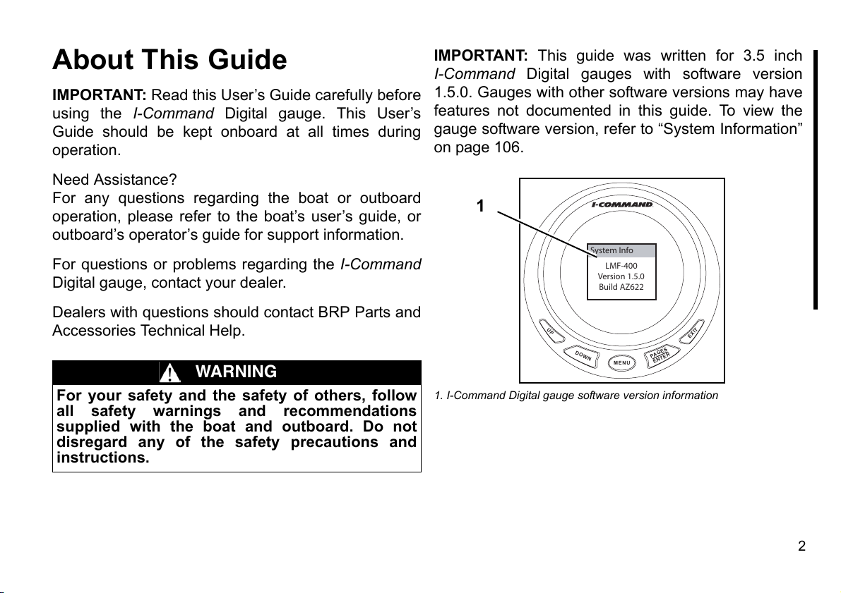
IMPORTANT: This guide was written for 3.5 inch
I-Command Digital gauges with software version
1.5.0. Gauges with other software versions may have
features not documented in this guide. To view the
gauge software version, refer to “System Information”
on page 106.
1
System Info
LMF-400
Version 1.5.0
Build AZ622
Dealers with questions should contact BRP Parts and
Accessories Technical Help.
WARNING
For your safety and the safety of others, follow
all safety warnings and recommendations
supplied with the boat and outboard. Do not
disregard any of the safety precautions and
instructions.
UP
DOWN
MENU
1. I-Command Digital gauge software version information
PA
ENTER
EXIT
GES
2
Page 5
TABLE OF CONTENTS
Installation
Description . . . . . . . . . . . . . . . . . . . . . . . . . . . . . . .5
Instruments . . . . . . . . . . . . . . . . . . . . . . . . . . . . . . .6
Network Devices . . . . . . . . . . . . . . . . . . . . . . . . . . .9
Network Setup . . . . . . . . . . . . . . . . . . . . . . . . . . . .14
Basic Setup and Operation
Power Up . . . . . . . . . . . . . . . . . . . . . . . . . . . . . . . .16
Boat Setup . . . . . . . . . . . . . . . . . . . . . . . . . . . . . . .17
Engine Data . . . . . . . . . . . . . . . . . . . . . . . . . . . . . .19
Information Displays . . . . . . . . . . . . . . . . . . . . . . . .20
Screen Settings . . . . . . . . . . . . . . . . . . . . . . . . . . . .22
Change Units . . . . . . . . . . . . . . . . . . . . . . . . . . . . .26
Customizing Displays
Display Fuel Economy . . . . . . . . . . . . . . . . . . . . . .30
Add New Page . . . . . . . . . . . . . . . . . . . . . . . . . . . .32
Customizing Displays . . . . . . . . . . . . . . . . . . . . . . .38
Lock Pages . . . . . . . . . . . . . . . . . . . . . . . . . . . . . . .42
Accessing a Locked Page . . . . . . . . . . . . . . . . . . . .44
Removing Pages . . . . . . . . . . . . . . . . . . . . . . . . . . .46
Page Scrolling . . . . . . . . . . . . . . . . . . . . . . . . . . . . .48
Pop-Ups . . . . . . . . . . . . . . . . . . . . . . . . . . . . . . . . .50
Stay-on Time . . . . . . . . . . . . . . . . . . . . . . . . . . . . . .52
Sleep Mode . . . . . . . . . . . . . . . . . . . . . . . . . . . . . . .54
Advanced Setup and Operation
Configure Fluid Level Sensor . . . . . . . . . . . . . . . . 58
Fuel and Fluid Level Sensor Calibration . . . . . . . . 61
Fuel Management . . . . . . . . . . . . . . . . . . . . . . . . . 64
Configure Sensors . . . . . . . . . . . . . . . . . . . . . . . . . 70
Change Ranges . . . . . . . . . . . . . . . . . . . . . . . . . . . 74
Winterize . . . . . . . . . . . . . . . . . . . . . . . . . . . . . . . . 76
Audio Settings . . . . . . . . . . . . . . . . . . . . . . . . . . . . 79
Reset Values . . . . . . . . . . . . . . . . . . . . . . . . . . . . . 80
Sonar Alarms . . . . . . . . . . . . . . . . . . . . . . . . . . . . . 82
Troubleshooting
Gauge Flashes Four Dashes . . . . . . . . . . . . . . . . . 86
Engine Warnings . . . . . . . . . . . . . . . . . . . . . . . . . . 87
Evinrude E-TEC Engine Warnings . . . . . . . . . . . . 88
Network Troubleshooting Chart . . . . . . . . . . . . . . . 90
Updating Gauge Software
Software Updates . . . . . . . . . . . . . . . . . . . . . . . . . 94
Reference Information
Abbreviation Tables . . . . . . . . . . . . . . . . . . . . . . . . 102
Abbreviations Key . . . . . . . . . . . . . . . . . . . . . . . . . 104
System Information . . . . . . . . . . . . . . . . . . . . . . . . 106
Product Warranty
Warranty Statement . . . . . . . . . . . . . . . . . . . . . . . . 107
3
Page 6

Installation
4
Page 7
Description
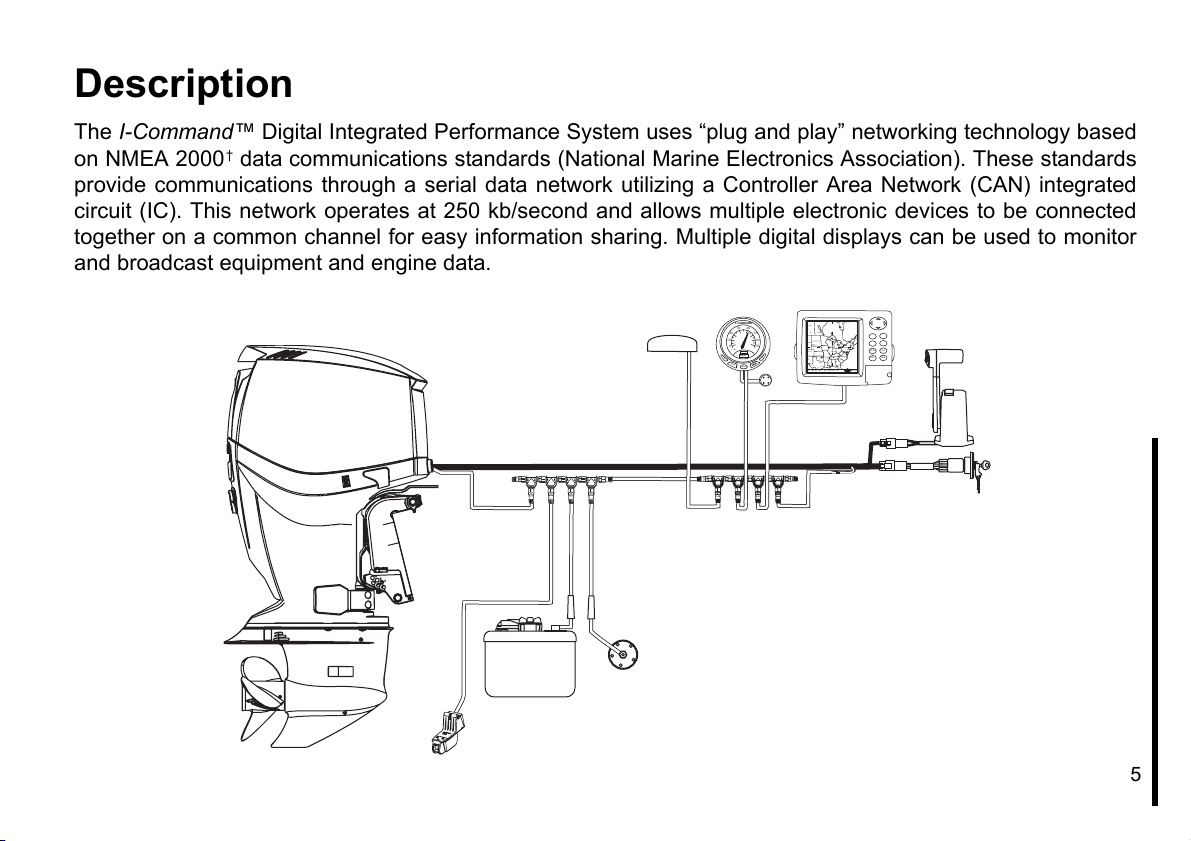
The I-Command™ Digital Integrated Performance System uses “plug and play” networking technology based
on NMEA 2000† data communications standards (National Marine Electronics Association). These standards
provide communications through a serial data network utilizing a Controller Area Network (CAN) integrated
circuit (IC). This network operates at 250 kb/second and allows multiple electronic devices to be connected
together on a common channel for easy information sharing. Multiple digital displays can be used to monitor
and broadcast equipment and engine data.
20 50
10 60
0 70
x 100
U
P
D
OWN
30 40
RPM
4257
MENU
Canada
Winnipeg
Quebec
United
Toronto
States
Chicago
New York
MENU EXIT
Indianapolis
Denver
T
XI
E
S
GE
PasoPaso
R
PA
TE
N
E
N
Dallas
Houston
42°21,770’ W 87°49.7 15’
ENT PWR
Memphis
Jacksonville
2000 mi
5
Page 8

Instruments
Spacing of Instruments
The minimum distances between instruments on a panel should be as follows:
•3 13/16 (112 mm) center to center for 3 1/2 in. instruments
•3 1/4 in. (95.5 mm) center to center for 3 1/2 in. instruments to 2 in. instruments
•2 5/8 in. (77 mm) center to center for 2 in. instruments
Panel Thickness
Instruments can be mounted in panels up to 1 in. thick.
Hole Sizes
IMPORTANT: Check space behind panel to be sure adequate clearance for instruments exists before drilling
panel.
3 1/2 in. Multifunction Gauge
Cut 3 3/8 in. (99 mm) diameter hole in panel for 3 1/2 in. instruments.
Fastening to Panel
Insert instrument into panel hole. Install bracket and tighten nuts finger tight.
6
Page 9
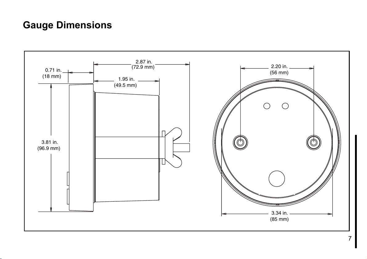
Gauge Dimensions
0.71 in.
(18 mm)
3.81 in.
(96.9 mm)
2.87 in.
(72.9 mm)
1.95 in.
(49.5 mm)
2.20 in.
(56 mm)
3.34 in.
(85 mm)
7
Page 10
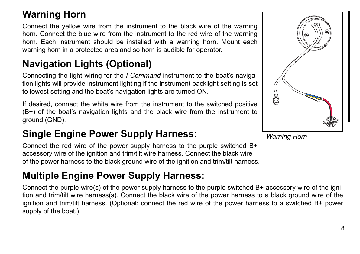
Warning Horn
Connect the yellow wire from the instrument to the black wire of the warning
horn. Connect the blue wire from the instrument to the red wire of the warning
horn. Each instrument should be installed with a warning horn. Mount each
warning horn in a protected area and so horn is audible for operator.
Navigation Lights (Optional)
Connecting the light wiring for the I-Command instrument to the boat’s naviga-
tion lights will provide instrument lighting if the instrument backlight setting is set
to lowest setting and the boat’s navigation lights are turned ON.
If desired, connect the white wire from the instrument to the switched positive
(B+) of the boat’s navigation lights and the black wire from the instrument to
ground (GND).
Single Engine Power Supply Harness:
Connect the red wire of the power supply harness to the purple switched B+
accessory wire of the ignition and trim/tilt wire harness. Connect the black wire
of the power harness to the black ground wire of the ignition and trim/tilt harness.
Warning Horn
Multiple Engine Power Supply Harness:
Connect the purple wire(s) of the power supply harness to the purple switched B+ accessory wire of the igni-
tion and trim/tilt wire harness(s). Connect the black wire of the power harness to a black ground wire of the
ignition and trim/tilt harness. (Optional: connect the red wire of the power harness to a switched B+ power
supply of the boat.)
8
Page 11
Network Devices
Also see the “Network Specification Diagram” on page 10.
Buss Length
The distance between any two points on the network must not exceed 100 meters (328 ft.).
Measure the distance from the Tee-connector to the last device at each end of the network. Device cable
lengths at the ends of the network must be included in the total network buss length calculation.
Devices
Devices may be installed in any order. When installing temperature, pressure and fluid level sensors, install
one device at a time. Configure the device, see “Advanced Setup and Operation” on page 57, then repeat this
process for each sensor device being installed.
Device Cable Lengths
•Must not exceed 6 meters (19 ft.) for single device cable lengths
•Must not exceed 78 meters (256 ft.) for total device cable lengths
Maximum Number of Devices
A maximum of 50 devices can be attached to a network.
IMPORTANT: There should be no “open” or unused network device connectors. Remove unused network
device connectors.
9
Page 12
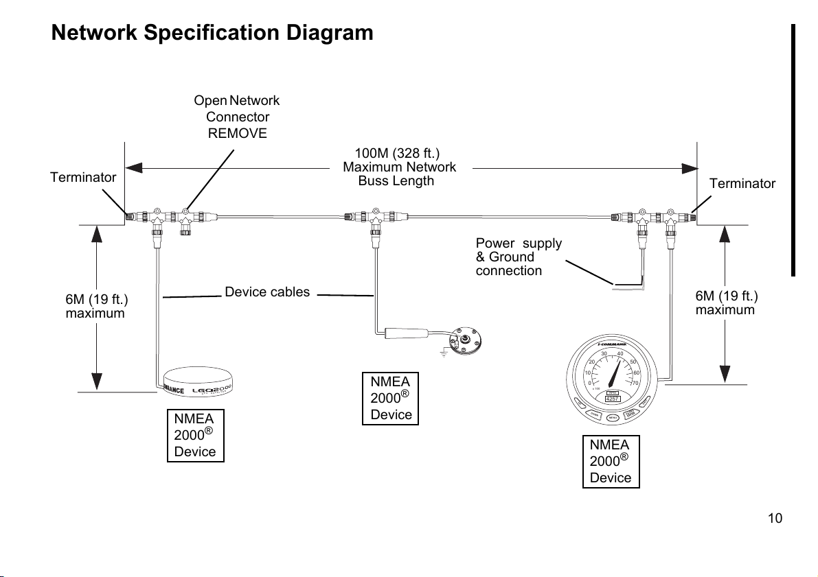
Network Specification Diagram
Open Network
Connector
REMOVE
100M (328 ft.)
Terminator
6M (19 ft.)
maximum
P
G
NMEA
®
2000
Device
Device cables
R
E
V
I
E
C
E
R
S
Maximum Network
Buss Length
NMEA
®
2000
Device
Power supply
& Ground
connection
30 40
20 50
10 60
0 70
x 100
RPM
4257
UP
DOWN
MENU
NMEA
2000
Device
Terminator
6M (19 ft.)
maximum
EXIT
PAGES
ENTER
®
10
Page 13
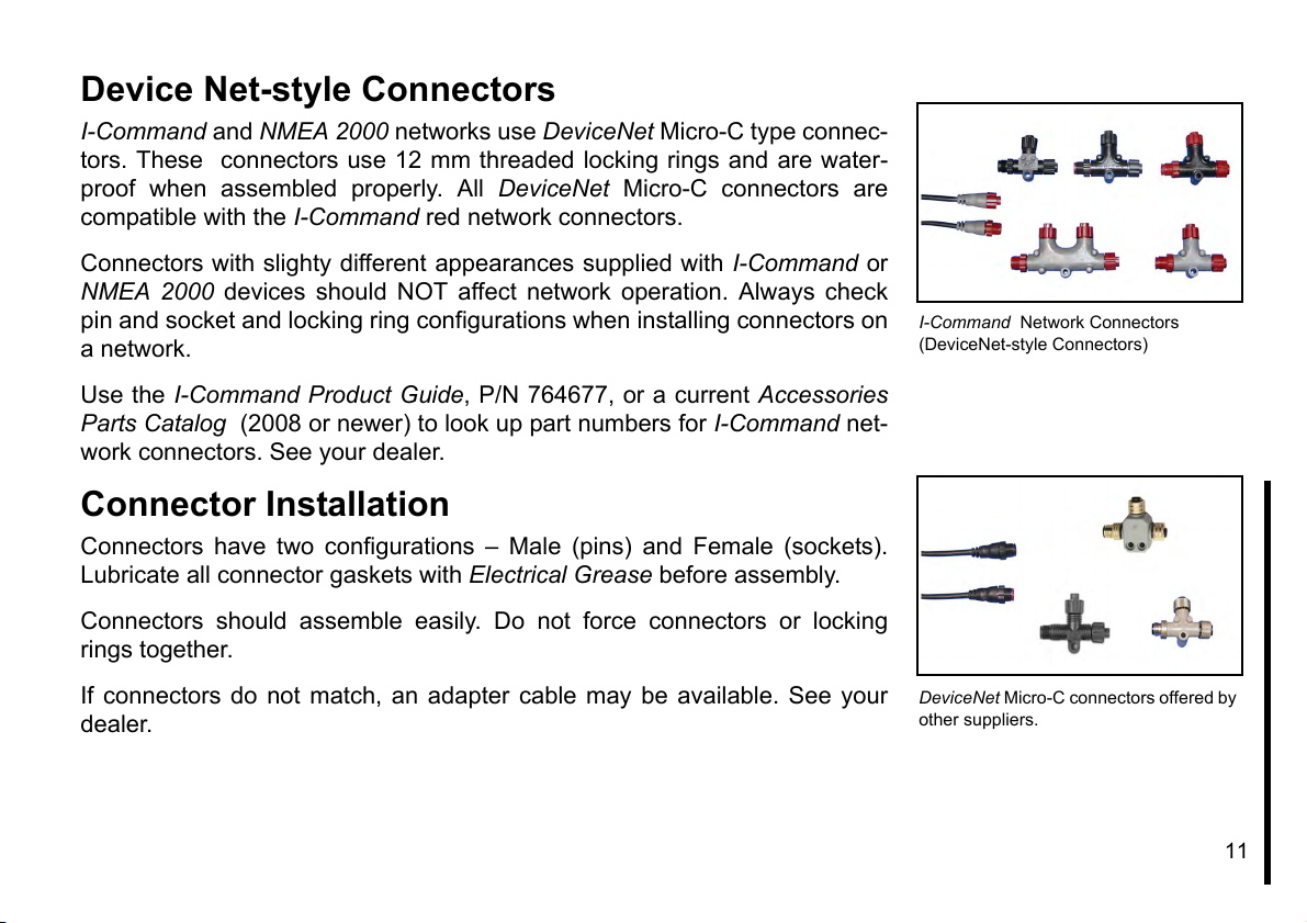
Device Net-style Connectors
I-Command and NMEA 2000 networks use DeviceNet Micro-C type connec-
tors. These connectors use 12 mm threaded locking rings and are water-
proof when assembled properly. All DeviceNet Micro-C connectors are
compatible with the I-Command red network connectors.
Connectors with slighty different appearances supplied with I-Command or
NMEA 2000 devices should NOT affect network operation. Always check
pin and socket and locking ring configurations when installing connectors on
a network.
Use the I-Command Product Guide, P/N 764677, or a current Accessories
Parts Catalog (2008 or newer) to look up part numbers for I-Command net-
work connectors. See your dealer.
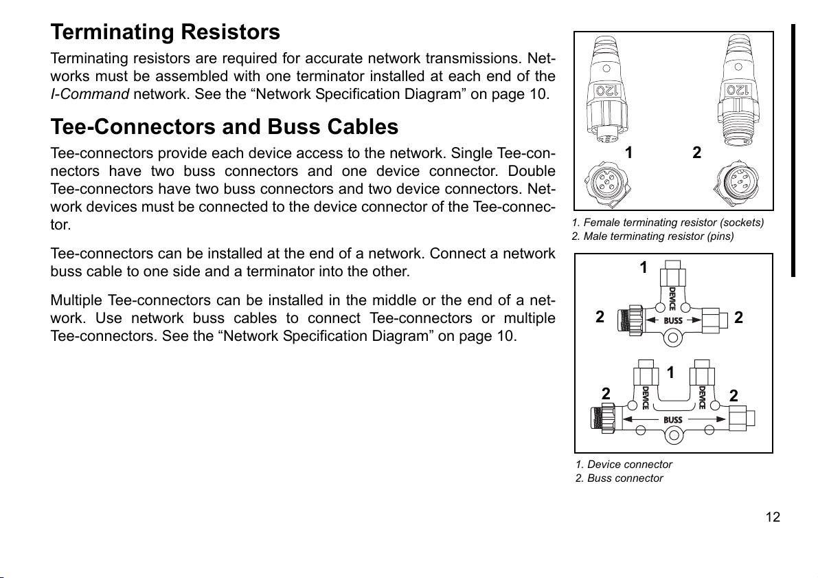
Connector Installation
Connectors have two configurations – Male (pins) and Female (sockets).
Lubricate all connector gaskets with Electrical Grease before assembly.
Connectors should assemble easily. Do not force connectors or locking
rings together.
I-Command Network Connectors
(DeviceNet-style Connectors)
If connectors do not match, an adapter cable may be available. See your
dealer.
DeviceNet Micro-C connectors offered by
other suppliers.
11
Page 14
Terminating Resistors
BUSS
DEVICE
DEVICE
DEVICE
BUSS
Terminating resistors are required for accurate network transmissions. Net-
works must be assembled with one terminator installed at each end of the
I-Command network. See the “Network Specification Diagram” on page 10.
Tee-Connectors and Buss Cables
Tee-connectors provide each device access to the network. Single Tee-con-
nectors have two buss connectors and one device connector. Double
Tee-connectors have two buss connectors and two device connectors. Net-
work devices must be connected to the device connector of the Tee-connec-
tor.
Tee-connectors can be installed at the end of a network. Connect a network
buss cable to one side and a terminator into the other.
Multiple Tee-connectors can be installed in the middle or the end of a net-
work. Use network buss cables to connect Tee-connectors or multiple
Tee-connectors. See the “Network Specification Diagram” on page 10.
1
1. Female terminating resistor (sockets)
2. Male terminating resistor (pins)
2
1
2
2
1
2
1. Device connector
2. Buss connector
2
12
Page 15
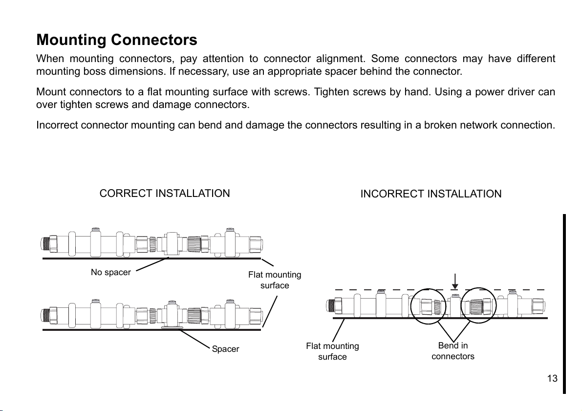
Mounting Connectors
When mounting connectors, pay attention to connector alignment. Some connectors may have different
mounting boss dimensions. If necessary, use an appropriate spacer behind the connector.
Mount connectors to a flat mounting surface with screws. Tighten screws by hand. Using a power driver can
over tighten screws and damage connectors.
Incorrect connector mounting can bend and damage the connectors resulting in a broken network connection.
CORRECT INSTALLATION
No spacer
Spacer
Flat mounting
surface
Flat mounting
surface
INCORRECT INSTALLATION
Bend in
connectors
13
Page 16

Network Setup
IMPORTANT: Set “ENGINE OPTIONS” on Evinrude E-TEC outboards
before power is applied to the I-Command Network.
Engine Options
Use Evinrude Diagnostics software to set “ENGINE OPTIONS”.
Settings include:
•Set multi engine identity (engine count and engine position)
•Calibrate trim sensor
•Water pressure transducer (ONLY if equipped with water pressure
transducer that is installed on engine block, P/N 5006214)
See your dealer if set “ENGINE OPTIONS” has not been completed.
Evinrude Diagnostics software, set engine
options
14
Page 17
Basic Setup and Operation
15
Page 18
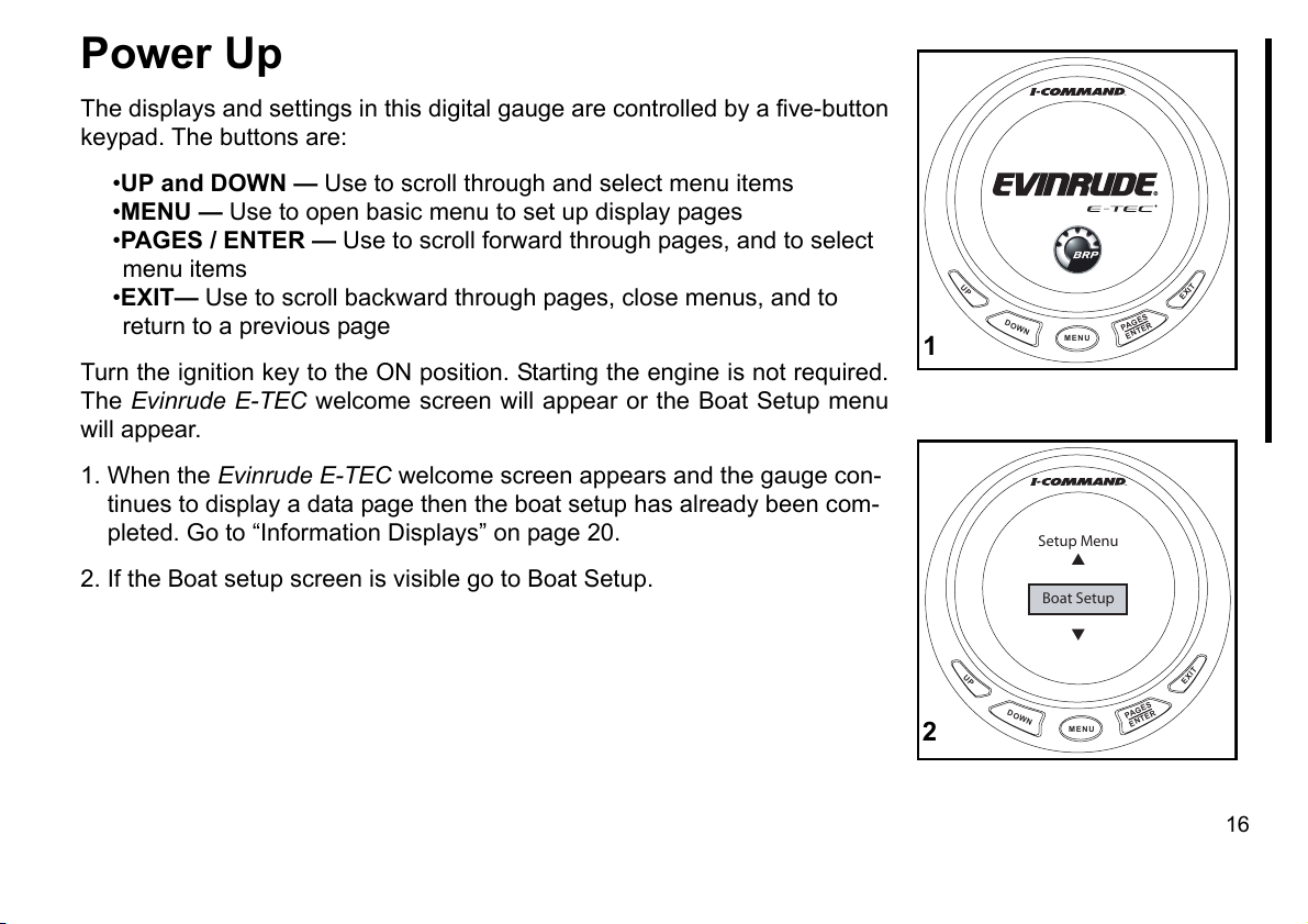
Power Up
The displays and settings in this digital gauge are controlled by a five-button
keypad. The buttons are:
•UP and DOWN — Use to scroll through and select menu items
•MENU — Use to open basic menu to set up display pages
•PAGES / ENTER — Use to scroll forward through pages, and to select
menu items
•EXIT— Use to scroll backward through pages, close menus, and to
return to a previous page
Turn the ignition key to the ON position. Starting the engine is not required.
The Evinrude E-TEC welcome screen will appear or the Boat Setup menu
will appear.
1. When the Evinrude E-TEC welcome screen appears and the gauge con-
tinues to display a data page then the boat setup has already been com-
pleted. Go to “Information Displays” on page 20.
2. If the Boat setup screen is visible go to Boat Setup.
UP
DOWN
DOWN
MENU
Setup Menu
Boat Setup
MENU
1
UP
2
PA
ENTER
PA
GES
GES
ENTER
EXIT
EXIT
16
Page 19
Boat Setup
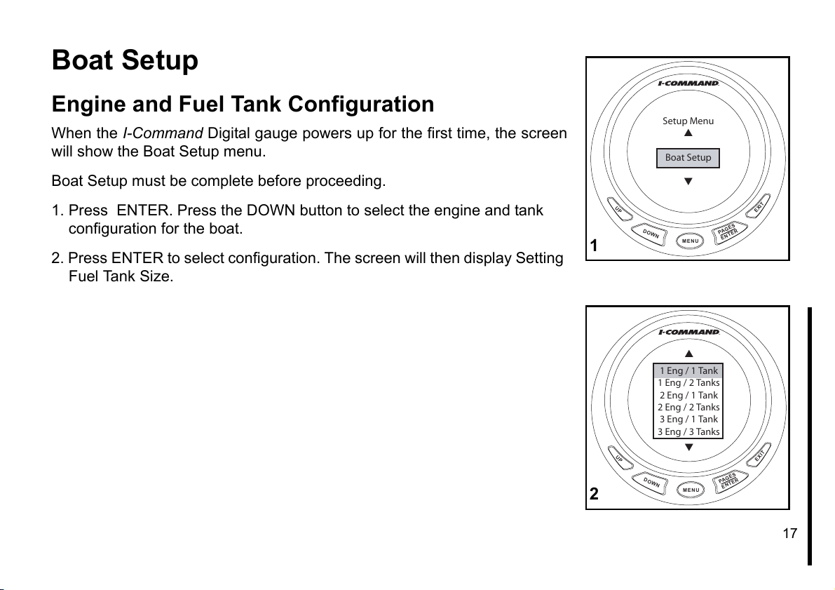
Engine and Fuel Tank Configuration
When the I-Command Digital gauge powers up for the first time, the screen
will show the Boat Setup menu.
Boat Setup must be complete before proceeding.
1. Press ENTER. Press the DOWN button to select the engine and tank
configuration for the boat.
2. Press ENTER to select configuration. The screen will then display Setting
Fuel Tank Size.
Setup Menu
Boat Setup
UP
DOWN
1 Eng / 1 Tank
1 Eng / 2 Tanks
2 Eng / 1 Tank
2 Eng / 2 Tanks
3 Eng / 1 Tank
3 Eng / 3 Tanks
DOWN
MENU
MENU
1
UP
2
PAGES
ENTER
PAGES
ENTER
EXIT
EXIT
17
Page 20
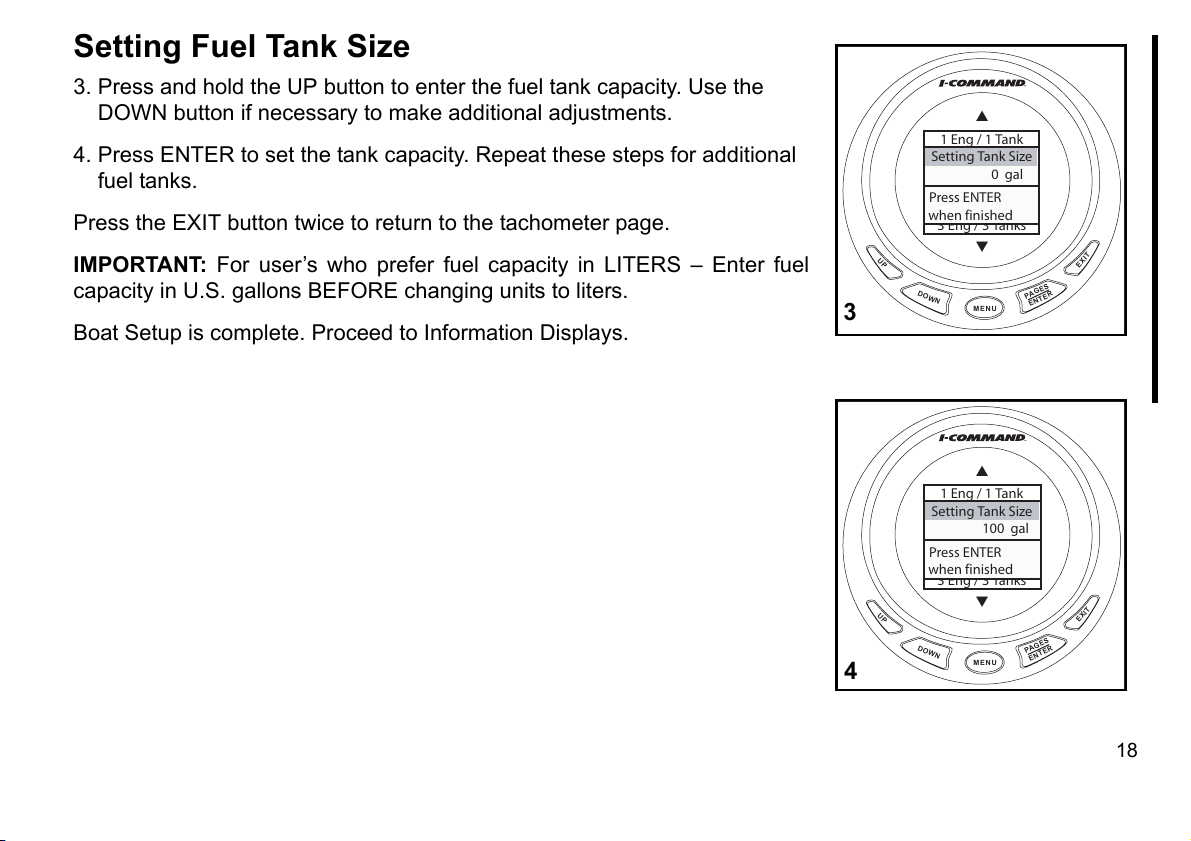
Setting Fuel Tank Size
3. Press and hold the UP button to enter the fuel tank capacity. Use the
DOWN button if necessary to make additional adjustments.
4. Press ENTER to set the tank capacity. Repeat these steps for additional
fuel tanks.
Press the EXIT button twice to return to the tachometer page.
IMPORTANT: For user’s who prefer fuel capacity in LITERS – Enter fuel
capacity in U.S. gallons BEFORE changing units to liters.
Boat Setup is complete. Proceed to Information Displays.
1 Eng / 1 Tank
1 Eng / 2 Tanks
Setting Tank Size
2 Eng / 1 Tank
0 gal
2 Eng / 2 Tanks
Press ENTER
3 Eng / 1 Tank
when finished
3 Eng / 3 Tanks
DOWN
MENU
PAGES
ENTER
EXIT
UP
3
1 Eng / 1 Tank
1 Eng / 2 Tanks
Setting Tank Size
2 Eng / 1 Tank
100 gal
2 Eng / 2 Tanks
Press ENTER
3 Eng / 1 Tank
when finished
3 Eng / 3 Tanks
DOWN
MENU
PAGES
ENTER
EXIT
UP
4
18
Page 21
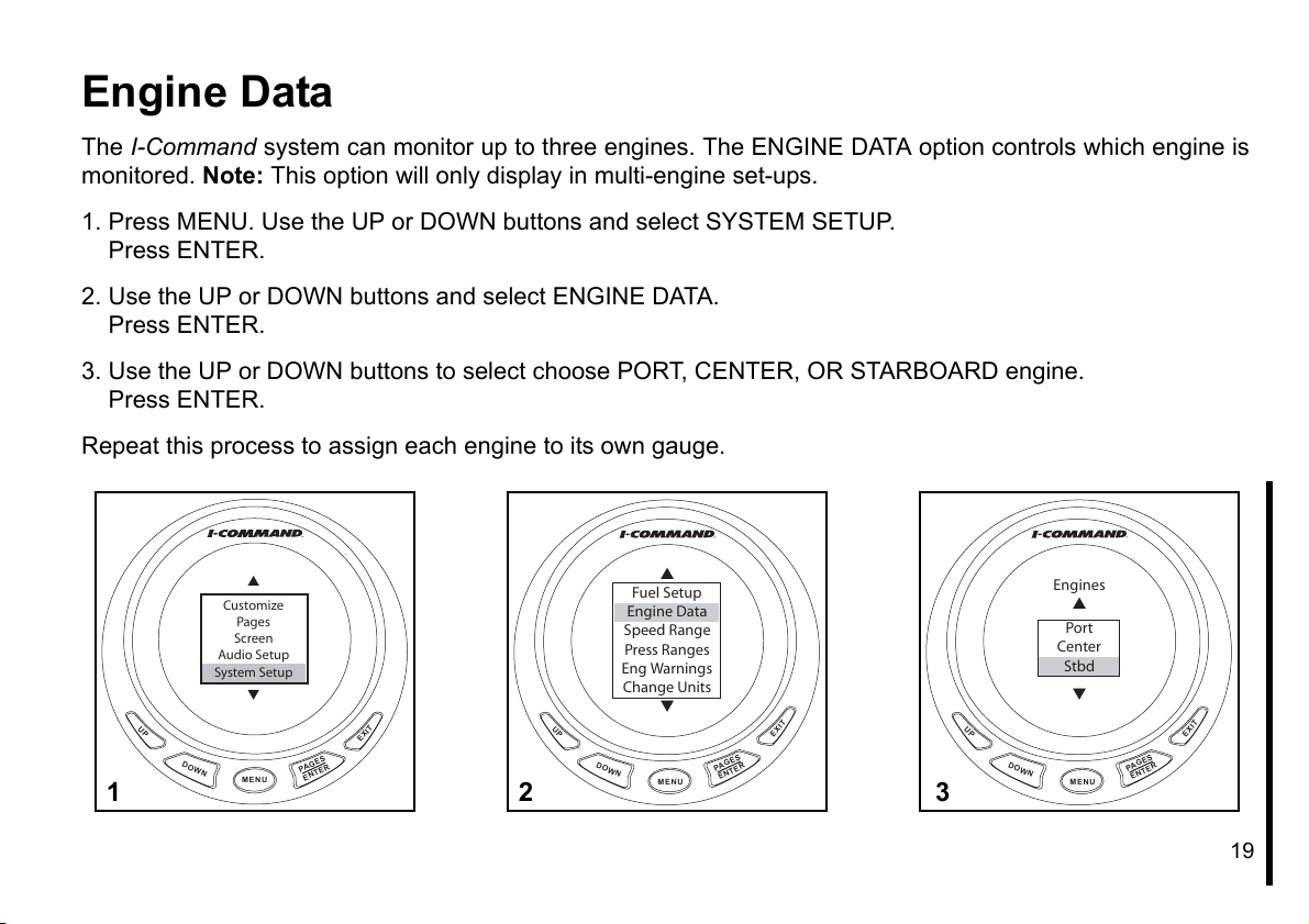
Engine Data
The I-Command system can monitor up to three engines. The ENGINE DATA option controls which engine is
monitored. Note: This option will only display in multi-engine set-ups.
1. Press MENU. Use the UP or DOWN buttons and select SYSTEM SETUP.
Press ENTER.
2. Use the UP or DOWN buttons and select ENGINE DATA.
Press ENTER.
3. Use the UP or DOWN buttons to select choose PORT, CENTER, OR STARBOARD engine.
Press ENTER.
Repeat this process to assign each engine to its own gauge.
Customize
Pages
Screen
Audio Setup
System Setup
UP
DOWN
MENU
PA
ENTER
EXIT
ES
G
1
UP
2
Fuel Setup
Engine Data
Speed Range
Press Ranges
Eng Warnings
Change Units
DOWN
MENU
PA
ENTER
Engines
Port
Center
Stbd
EXIT
ES
G
UP
DOWN
3
MENU
PA
ENTER
EXIT
ES
G
19
Page 22
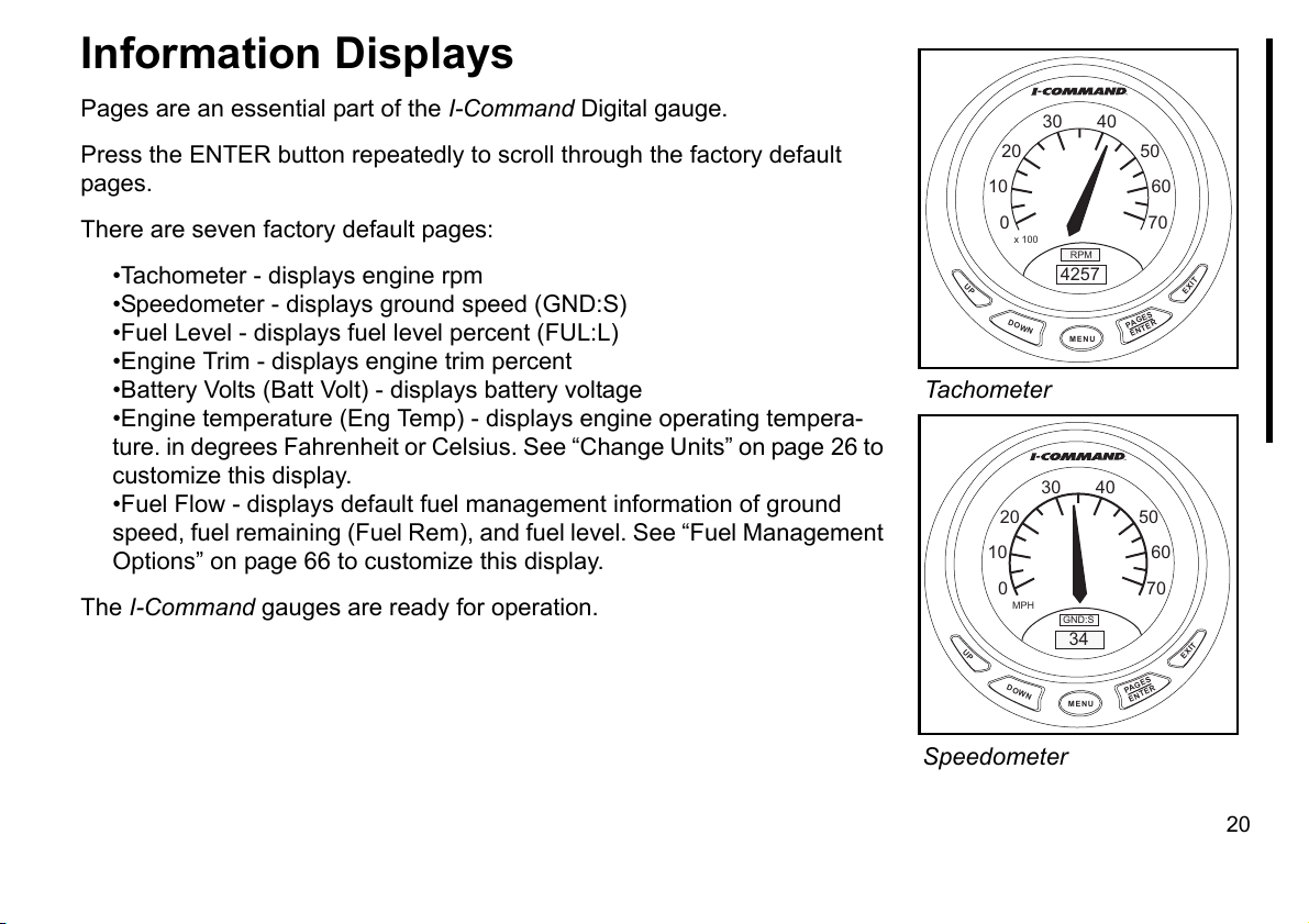
Information Displays
Pages are an essential part of the I-Command Digital gauge.
Press the ENTER button repeatedly to scroll through the factory default
pages.
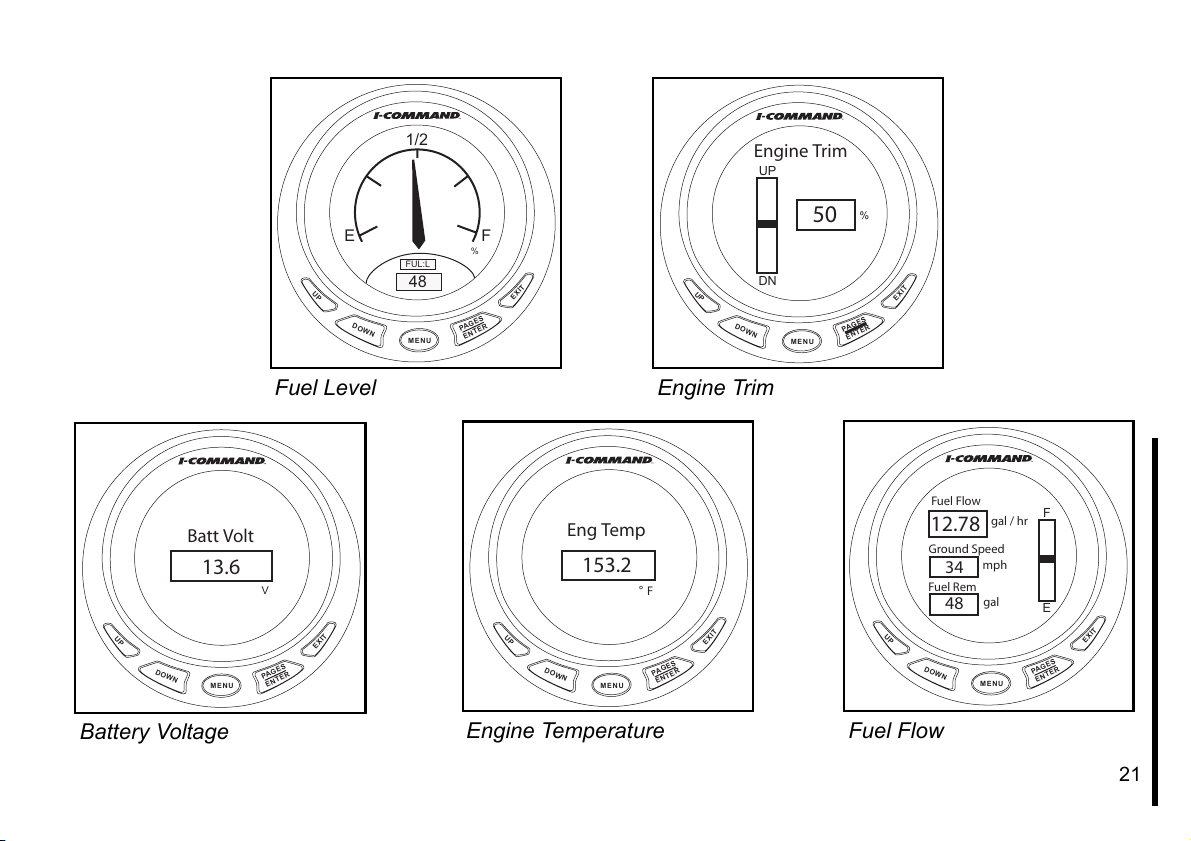
There are seven factory default pages:
•Tachometer - displays engine rpm
•Speedometer - displays ground speed (GND:S)
•Fuel Level - displays fuel level percent (FUL:L)
•Engine Trim - displays engine trim percent
•Battery Volts (Batt Volt) - displays battery voltage
•Engine temperature (Eng Temp) - displays engine operating tempera-
ture. in degrees Fahrenheit or Celsius. See “Change Units” on page 26 to
customize this display.
•Fuel Flow - displays default fuel management information of ground
speed, fuel remaining (Fuel Rem), and fuel level. See “Fuel Management
Options” on page 66 to customize this display.
The I-Command gauges are ready for operation.
20 50
10 60
0 70
x 100
UP
DOWN
Tachometer
20 50
10 60
0 70
MPH
UP
DOWN
30 40
RPM
4257
MENU
30 40
GND:S
34
MENU
PA
PA
GES
ENTER
GES
ENTER
EXIT
EXIT
Speedometer
20
Page 23
1/2
E F
FUL:L
UP
DOWN
48
MENU
PAGES
ENTER
Engine Trim
UP
%
DOWN
DN
MENU
EXIT
UP
50
PA
ENTER
%
EXIT
ES
G
Batt Volt
13.6
UP
DOWN
MENU
Battery Voltage
Fuel Level
V
EXIT
GES
PA
ENTER
Eng Temp
153.2
° F
UP
DOWN
MENU
Engine Temperature
Engine Trim
EXIT
GES
PA
ENTER
UP
DOWN
Fuel Flow
Fuel F low
12.78
Ground Speed
mph
34
Fuel R em
gal
48
MENU
gal / hr
PAGES
ENTER
F
E
EXIT
21
Page 24
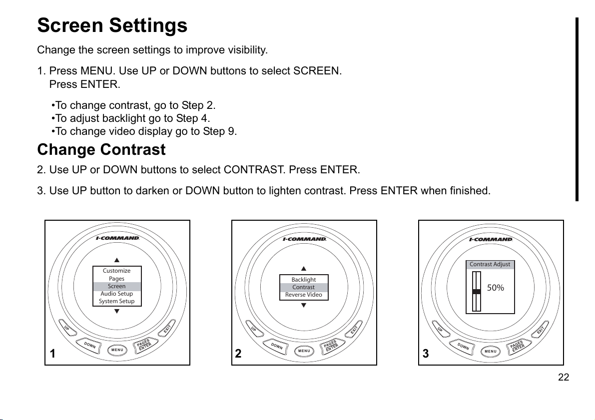
Screen Settings
Change the screen settings to improve visibility.
1. Press MENU. Use UP or DOWN buttons to select SCREEN.
Press ENTER.
•To change contrast, go to Step 2.
•To adjust backlight go to Step 4.
•To change video display go to Step 9.
Change Contrast
2. Use UP or DOWN buttons to select CONTRAST. Press ENTER.
3. Use UP button to darken or DOWN button to lighten contrast. Press ENTER when finished.
Customize
Pages
Screen
Audio Setup
System Setup
UP
DOWN
1
MENU
PA
ENTER
EXIT
ES
G
UP
2
Reverse Video
DOWN
Backlight
Contrast
MENU
PA
ENTER
EXIT
ES
G
UP
3
Contrast Adjust
DOWN
50%
MENU
PA
ENTER
EXIT
GES
22
Page 25
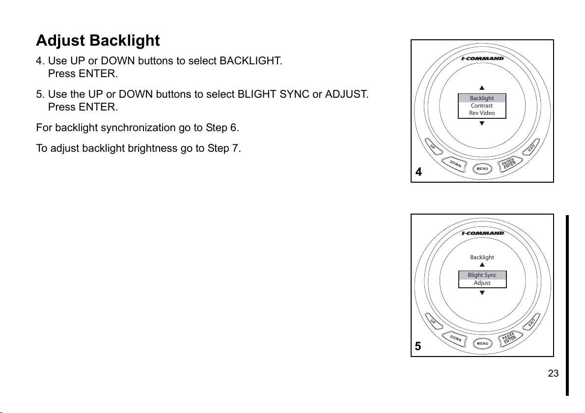
Adjust Backlight
4. Use UP or DOWN buttons to select BACKLIGHT.
Press ENTER.
5. Use the UP or DOWN buttons to select BLIGHT SYNC or ADJUST.
Press ENTER.
For backlight synchronization go to Step 6.
To adjust backlight brightness go to Step 7.
Backlight
Contrast
Rev Video
UP
DOWN
4
MENU
Backlight
Blight Sync
Adjust
PA
ENTER
EXIT
GES
UP
DOWN
5
MENU
PAGES
ENTER
EXIT
23
Page 26
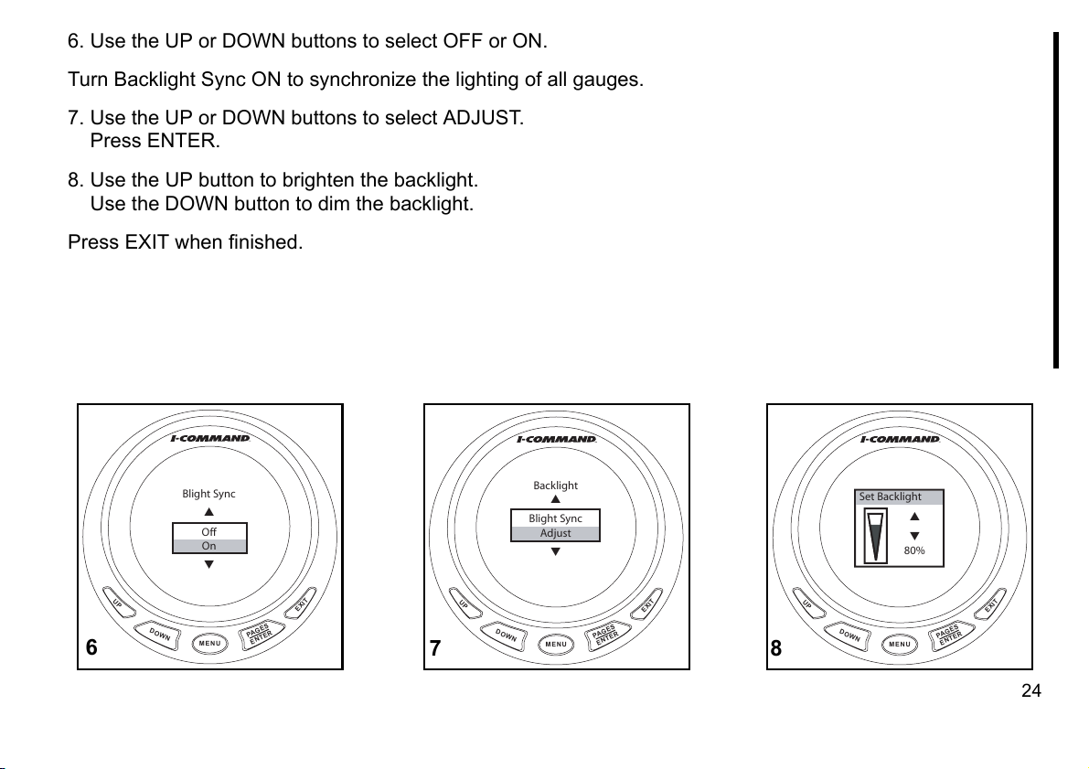
6. Use the UP or DOWN buttons to select OFF or ON.
Turn Backlight Sync ON to synchronize the lighting of all gauges.
7. Use the UP or DOWN buttons to select ADJUST.
Press ENTER.
8. Use the UP button to brighten the backlight.
Use the DOWN button to dim the backlight.
Press EXIT when finished.
DOWN
Backlight
Blight Sync
Adjust
MENU
PA
ENTER
Set Backlight
80%
EXIT
GES
UP
DOWN
8
MENU
PA
ENTER
EXIT
GES
Blight Sync
Off
On
UP
DOWN
6
MENU
PA
ENTER
EXIT
GES
UP
7
24
Page 27
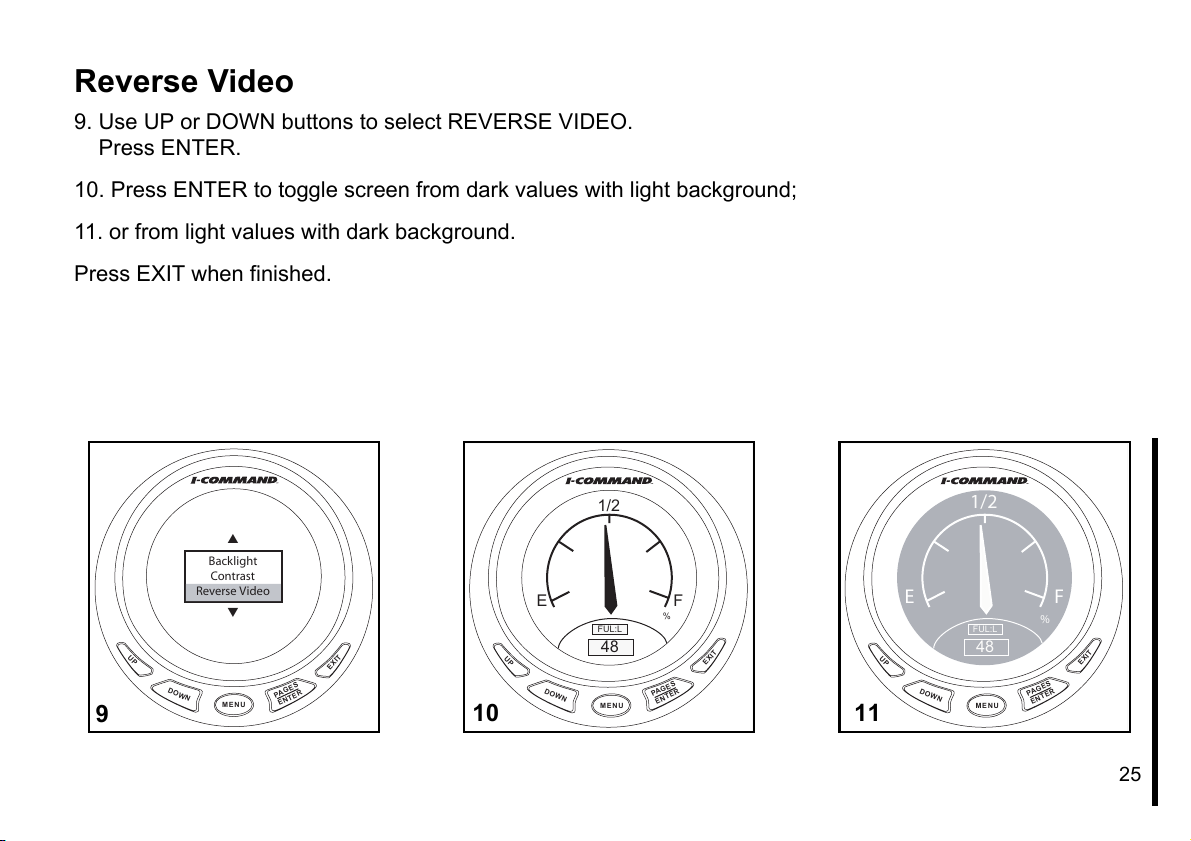
Reverse Video
9. Use UP or DOWN buttons to select REVERSE VIDEO.
Press ENTER.
10. Press ENTER to toggle screen from dark values with light background;
11. or from light values with dark background.
Press EXIT when finished.
DOWN
1/2
FUL:L
48
MENU
PA
ENTER
%
EXIT
ES
G
1/2
Backlight
Contrast
Reverse Video
UP
DOWN
9
MENU
PA
ENTER
EXIT
ES
G
10
E F
FUL:L
DOWN
48
MENU
UP
PA
%
ES
G
ENTER
EXIT
E F
UP
11
25
Page 28
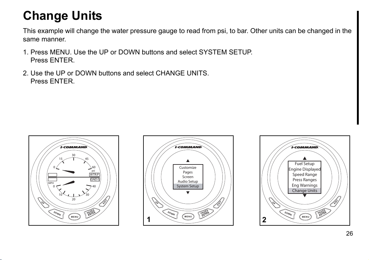
Change Units
This example will change the water pressure gauge to read from psi, to bar. Other units can be changed in the
same manner.
1. Press MENU. Use the UP or DOWN buttons and select SYSTEM SETUP.
Press ENTER.
2. Use the UP or DOWN buttons and select CHANGE UNITS.
Press ENTER.
30
15 45
0 60
MPH
0 40
10 30
UP
DOWN
20
MENU
PA
ENTER
psi
WTR:P
GND:S
GES
EXIT
Customize
Pages
Screen
Audio Setup
System Setup
UP
DOWN
1
MENU
PA
ENTER
EXIT
GES
UP
2
Fuel Setup
Engine Displayed
Speed Range
Press Ranges
Eng Warnings
Change Units
DOWN
MENU
PAGES
ENTER
EXIT
26
Page 29
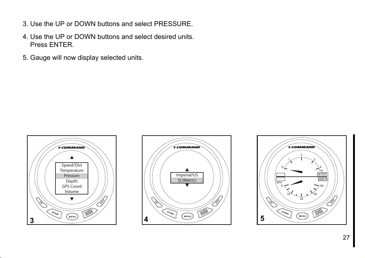
3. Use the UP or DOWN buttons and select PRESSURE.
4. Use the UP or DOWN buttons and select desired units.
Press ENTER.
5. Gauge will now display selected units.
Speed/Dist
Temperature
Pressure
Depth
GPS Coord
Volume
DOWN
MENU
PA
ENTER
EXIT
GES
UP
3
UP
4
DOWN
Imperial/US
SI (Metric)
MENU
PA
ENTER
EXIT
ES
G
5
0 4
MPH
0 40
UP
DOWN
2
1 3
10 30
20
MENU
WTR:P
PAGES
ENTER
bar
GND:S
EXIT
27
Page 30
Setup Notes
28
Page 31

Customizing Displays
29
Page 32

Display Fuel Economy
1. Press the ENTER button repeatedly to scroll to the Fuel Flow page.
The center data box is Ground Speed.
2. Press MENU.
Use the UP or DOWN buttons to select CUSTOMIZE.
Press ENTER.
Fuel F low
12.78
Ground Speed
34
Fuel R em
48
UP
DOWN
DOWN
MENU
Customize
Pages
Screen
Audio Setup
System Setup
MENU
1
UP
2
gal / hr
mph
gal
PAGES
ENTER
PA
ENTER
F
E
EXIT
EXIT
GES
30
Page 33

3. Use UP or DOWN buttons to select CENTER DATA.
Press ENTER.
4. Press UP or DOWN button to select FUEL ECONOMY.
Press ENTER.
5. Press EXIT twice to return to fuel manager page.
Fuel Economy (MPG) is now activated.
UP
Fuel F low
12.78
Fuel Economy
3.56
Fuel R em
48
DOWN
mpg
gal
MENU
gal / hr
PA
ENTER
F
E
EXIT
GES
Top Data
Center Data
Bottom Data
UP
DOWN
3
MENU
PAGES
ENTER
EXIT
UP
DOWN
4
Fuel Flow
Fuel Economy
F Consumption
Fuel Remaining
MENU
PA
ENTER
EXIT
GES
5
31
Page 34

Add New Page
Page displays can be presented in analog or digital format as single, dual, or
quad displays.
In addition to analog or digital gauge displays, seven other pages can be
added. They are:
•Trim Tabs - requires sending unit
•GPS Position - requires GPS module
•Rudder - requires sending unit
•Clock - requires GPS module
•Fuel Manager (labeled as Fuel Flow, also a default page)
•Engine Trim (also a default page)
•Engine Diagnostics
•Synchronizer – displays RPM for up to three engines, allowing users to
synchronize the engines for smoother performance.
Note: Only supported in multi-engine setups.
This example will add an Engine Diagnostics page.
1. Press MENU.
Use UP or DOWN buttons to select PAGES.
Press ENTER.
2. Press ENTER to select ADD PAGE.
Customize
Pages
Screen
Audio Setup
System Setup
UP
DOWN
Add Page
Remove Page
Page Scrolling
Popups Setup
DOWN
MENU
MENU
1
UP
2
GES
PA
ENTER
PA
ENTER
EXIT
EXIT
ES
G
32
Page 35

3. Use the UP or DOWN buttons to select Diagnostics.
Press ENTER.
4. Press ENTER again to confirm.
5. The Engine Diagnostic page will now display.
Trim Tabs
GPS Position
Rudder
Clock
Engine Trim
Diagnostics
DOWN
MENU
PAGES
ENTER
EXIT
UP
4
UP
3
Trim Tabs
Adding Page
GPS Position
Press ENTER
Rudder
to Add
Clock
Diagnostics
Engine Trim
Diagnostics
DOWN
MENU
Eng Diagnostics
Engine OK
PAGES
ENTER
EXIT
UP
DOWN
5
MENU
PAGES
ENTER
EXIT
33
Page 36

Add Analog Page
Analog page displays allow the following data combinations:
•Alt Voltage •GPS Speed
(speed over ground)
•Atmospheric Pressure •Paddle Wheel Speed (speed over water)
•Battery Voltage •Pitot Speed
•Engine Temp •Tachometer
•Fluid Level •Temperature
•Fuel Pressure •Engine Water Pressure
•Engine Oil Pressure •Engine Boost Pressure
•Transmission Oil Pressure
This example adds a dual analog gauge display. Single analog or quad ana-
log displays may be added by selecting those options.
1. Press MENU.
Use UP or DOWN buttons to select PAGES.
Press ENTER.
2. Press ENTER to select ADD PAGE.
Customize
Pages
Screen
Audio Setup
System Setup
UP
DOWN
Add Page
Remove Page
Page Scrolling
Popups Setup
DOWN
MENU
MENU
1
UP
2
PAGES
ENTER
PA
ENTER
EXIT
EXIT
ES
G
34
Page 37

3. Press UP button to select DUAL ANALOG.
Press ENTER.
4. Press ENTER again to confirm.
The Dual Analog gauge will now display.
To change the items displayed on any single, dual or quad analog gauge,
see “Customizing Displays” on page 38.
Single Analog
Dual Analog
Quad Analog
Single Digital
Dual Digital
Quad Digital
UP
3
E F
%
MPH
0 40
UP
DOWN
4
DOWN
MENU
1/2
10 30
20
MENU
PAGES
ENTER
PAGES
ENTER
EXIT
FUL:L
GND:S
EXIT
35
Page 38

Add Digital Page
Digital page displays allow the following data combinations:
•Alt Voltage •Fuel Remaining
•Atmospheric Pressure •GPS Speed (speed over ground)
•Battery Voltage •Paddle Wheel Speed (speed over water)
•Depth •Pitot Speed
•Engine Temperature •Tachometer
•Fuel Economy •Temperature
•Fuel Flow •Total Engine Hours
•Fuel Range •Throttle Percentage
•Fuel Consumption •Engine Water Pressure
•Fuel Used •Engine Oil Pressure
•Trip Fuel Used •Fuel Pressure
•Seasonal Fuel Used •Engine Boost Pressure
•Transmission Oil Pressure •Time
This example adds a quad digital gauge display. Single analog or dual digital
displays may be added by selecting those options.
1. Press MENU.
Use UP or DOWN buttons to select PAGES.
Press ENTER.
2. Press ENTER to select ADD PAGE.
Customize
Pages
Screen
Audio Setup
System Setup
UP
DOWN
Add Page
Remove Page
Page Scrolling
Popups Setup
DOWN
MENU
MENU
1
UP
2
PAGES
ENTER
PA
ENTER
EXIT
EXIT
ES
G
36
Page 39

3. Use UP or DOWN buttons to select QUAD DIGITAL.
Press ENTER.
4. Press ENTER again to confirm.
The Quad Digital gauge will now display.
To change the items displayed on any single, dual or quad digital gauge, see
“Customizing Displays” on page 38.
Single Analog
Dual Analog
Quad Analog
Single Digital
Dual Digital
Quad Digital
DOWN
MENU
RPM
Throttle Pct
Eng Hrs
Time
MENU
PA
%
Hrs
PAGES
ENTER
GES
ENTER
EXIT
EXIT
UP
3
UP
DOWN
4
37
Page 40

Customizing Displays
Changing Display Defaults
When adding pages, each single, dual or quad page has a default display. Use the CUSTOMIZE menu to
change which items are displayed on a page.
1. Press ENTER multiple times to scroll to page to customize.
Press MENU.
2. Use UP or DOWN buttons to select CUSTOMIZE.
Press ENTER.
3. Use UP or DOWN buttons to select GAUGE (if analog), or DATA BOX (if digital).
Press ENTER.
1/2
E F
%
MPH
0 40
10 30
DOWN
20
MENU
UP
1
PA
ENTER
FUL:L
GND:S
ES
G
EXIT
UP
2
DOWN
Customize
Pages
Screen
Audio Setup
System Setup
MENU
PA
ENTER
Top Gauge
Bottom Gauge
EXIT
GES
UP
DOWN
3
MENU
PA
ENTER
EXIT
GES
38
Page 41

4. Use UP or DOWN buttons to select desired display item.
Press ENTER.
5. Press EXIT once to return to Step 3 and change remaining items.
Press EXIT multiple times to return to display.
Display change will now appear.
Alt Voltage
Batt Voltage
Engine Temp
Eng Water Press
Fuel Pressure
UP
DOWN
4
MPH
UP
MENU
10 20
0 30
0 40
10 30
20
DOWN
MENU
PAGES
ENTER
WTR:P
G
PA
ENTER
EXIT
psi
GND:S
EXIT
ES
5
39
Page 42

Configure Time Display
1. Press MENU.
Use UP or DOWN buttons to select SYSTEM SETUP.
Press ENTER.
2. Use UP or DOWN buttons to select TIME CONFIG.
Press ENTER.
3. Use UP or DOWN buttons to select:
HOUR FORMAT, go to Step 4.
SHOW SECONDS, go to Step 5.
TIME ZONE go to Step 6.
Customize
Pages
Screen
Audio Setup
System Setup
UP
DOWN
1
MENU
PA
ENTER
EXIT
GES
2
Sonar Alarms
Eng/Tank Cfg
Time Config
Reset Values
Lock Pages
NMEA Info
UP
DOWN
MENU
PAGES
ENTER
EXIT
Time
Hour Format
Show Seconds
Time Zone
UP
DOWN
3
MENU
PAGES
ENTER
EXIT
40
Page 43

4. Use UP or DOWN buttons to select 12 or 24 hour display option.
Press ENTER.
5. Use UP or DOWN buttons to select YES or NO.
Press ENTER.
6. Use UP or DOWN buttons to select Time Zone.
Press ENTER.
7. Press EXIT multiple times to return to time display.
DOWN
GMT -3
GMT -2
GMT -1
GMT
GMT +1
GMT +2
MENU
PAGES
ENTER
EXIT
Show Seconds
No
Yes
UP
DOWN
5
MENU
PAGES
ENTER
EXIT
UP
6
Hour Format
24 hrs
12 hrs
UP
DOWN
4
MENU
Time
PAGES
ENTER
EXIT
13 : 35 : 47
pm
UP
DOWN
7
MENU
PA
ENTER
EXIT
GES
41
Page 44

Lock Pages
Viewing Pass Code
This feature prevents unauthorized users from changing select gauge settings. If you have the PASS CODE,
skip to step 4.
1. Press MENU. Use UP or DOWN buttons to select SYSTEM SETUP. Press ENTER.
2. Select NMEA INFO and press ENTER.
3. The PASS CODE is the last four digits of the SERIAL NUMBER.
For easy reference, write gauge serial number here: ______________
Press EXIT to return to the MENU.
Customize
Pages
Screen
Audio Setup
System Setup
UP
DOWN
1
MENU
PA
ENTER
EXIT
GES
UP
DOWN
2
Sonar Alarms
Eng/Tank Cfg
Time Config
Reset Values
Lock Pages
NMEA Info
MENU
PAGES
ENTER
EXIT
NMEA Info
Address: 10
Instance: 0
Serial Number:
6 5 4 3 2 1
NMEA Ver: 1.2.0
Bus Volt: 12.8
UP
DOWN
3
MENU
PA
ENTER
EXIT
GES
42
Page 45

Lock Pages
4. Use the UP or DOWN buttons to select LOCK PAGES.
Press ENTER.
5. Use the UP or DOWN buttons to change the active digit.
Use the MENU button to select the next digit.
Press ENTER to submit PASS CODE.
6. Use the UP or DOWN buttons to scroll through the list. Press the MENU button to view the next list.
Press ENTER to select page(s) to be locked. An "x" will appear in the box when a page is selected.
Press EXIT when selection is complete.
Sonar Alarms
Eng/Tank Cfg
Time Config
Reset Values
Lock Pages
NMEA Info
DOWN
MENU
PA
ENTER
EXIT
GES
UP
5
UP
4
Eng/Tank Cfg
Time Config
Enter Pass-Code
Reset Values
Lock Pages
0 0 0 0
NMEA Info
System Info
DOWN
MENU
UP
6
PA
ENTER
EXIT
ES
G
Eng/Tank Cfg
Locked Pages
Time Config
Customize
Reset Values
Pages
Lock Pages
x Fuel Setup
Eng/Tank Setup
NMEA Info
MENU key for more
System Info
DOWN
MENU
PA
ENTER
EXIT
ES
G
43
Page 46

Accessing a Locked Page
Locking pages prevents an unauthorized user from changing select gauge settings.
1. Press MENU.
Use UP or DOWN buttons to select SYSTEM SETUP.
2. Select desired page and press ENTER.
3. Enter the gauge PASS CODE.
Use the UP or DOWN buttons to change the active digit.
Use the MENU button to select the next digit.
Press ENTER to submit PASS CODE.
Customize
Pages
Screen
Audio Setup
System Setup
UP
DOWN
13
MENU
PA
ENTER
EXIT
GES
UP
DOWN
2
Fuel Setup
Speed Range
Press Ranges
Eng Warnings
Change Units
Bus Devices
MENU
PA
ES
G
ENTER
EXIT
UP
Fuel Setup
Speed Range
Press Ranges
Enter Pass-Code
Eng Warnings
0 0 0 0
Change Units
Bus Devices
DOWN
MENU
EXIT
PAGES
ENTER
44
Page 47

4. An incorrect entry will result in an INVALID PASS CODE message.
Press ENTER to start over.
5. Correct entry of pass code allows access to pages.
Use UP or DOWN buttons to select desired items and make changes.
6. When finished, press ENTER to return to gauge display.
DOWN
1/2
FUL:L
100
MENU
PAGES
ENTER
%
EXIT
Fuel Setup
Speed Range
Press Ranges
Pass-Code
Eng Warnings
Invalid
Change Units
Bus Devices
DOWN
MENU
PAGES
ENTER
EXIT
UP
4
UP
5
Refill Tank
Partial Fill
Eco Speed Src
Fuel Rem Src
Rst Trip Fuel
Rst Seasonal
DOWN
MENU
E F
UP
6
PA
ENTER
EXIT
GES
45
Page 48

Removing Pages
1. Press the ENTER button repeatedly to scroll to the page to be removed.
Press MENU.
2. Use UP or DOWN buttons to select PAGES.
Press ENTER.
20 70
x10
DOWN
DOWN
10 35
0 0
20 70
10 35
0 0
MENU
Customize
Pages
Screen
Audio Setup
System Setup
MENU
PAGES
ENTER
PAGES
ENTER
Volts
ALR:VBATT:V
WTR:P
EXIT
EXIT
Volts
WTR: T
°F psi
UP
1
UP
2
46
Page 49

3. Use UP or DOWN buttons to select REMOVE PAGE.
Press ENTER.
4. A confirmation message will appear.
Press ENTER to remove page.
The display will return to the next page.
Add Page
Remove Page
Page Scrolling
Popups Setup
UP
DOWN
3
UP
4
MENU
Removing Page
Press ENTER
to Remove
current Page
DOWN
MENU
PA
ENTER
PA
ENTER
EXIT
GES
EXIT
GES
47
Page 50

Page Scrolling
Pages can be viewed by manual or automatic scrolling.
Manual
To scroll through pages manually, use the ENTER and EXIT buttons to view
pages.
Automatic
To scroll through pages automatically, a viewing interval must be selected.
1. Press MENU.
Use the UP or DOWN buttons to select PAGES.
Press ENTER.
2. Use the UP or DOWN buttons, select PAGE SCROLLING.
Press ENTER.
Customize
Pages
Screen
Audio Setup
System Setup
UP
DOWN
1
MENU
PAGES
ENTER
EXIT
Add Page
Remove Page
Page Scrolling
Popups Setup
UP
DOWN
2
MENU
PAGES
ENTER
EXIT
48
Page 51

3. Use the UP or DOWN buttons to select SET TIME.
Press ENTER.
4. Use the UP or DOWN buttons to set time.
Select an interval between one and sixty seconds.
Press ENTER to set automatic scrolling interval.
Note: To turn off automatic page scrolling, repeat the first two steps. When
the Page Scrolling menu appears, select OFF. Then press ENTER.
Page Scrolling
Off
Set Time
UP
DOWN
3
MENU
Set Time
Add Page
Remove Page
5 sec
Page Scrolling
Press ENTER
Popups Setup
when finished
PA
ENTER
EXIT
GES
UP
DOWN
4
MENU
PAGES
ENTER
EXIT
49
Page 52

Pop-Ups
The Pop-Up feature alerts users when changes occur in a monitored cate-
gory (RPM, Engine Trim, Trim Tabs or Rudder). Pop-ups appear when a
user-specified incremental measurement is met. When an increment
changes, the main page for the category will pop up on the main display for
a preset duration. See “Stay-on Time” on page 52 to set the pop-up dura-
tion.
Setting a Pop-Up
This example illustrates setting the RPM Pop-Up. Engine trim, trim tabs and
rudder can be set up similarly.
1. Press MENU.
Use UP or DOWN buttons to select PAGES.
Press ENTER.
Customize
Pages
Screen
Audio Setup
System Setup
UP
DOWN
MENU
PAGES
ENTER
EXIT
1
2. Use the UP or DOWN button to select POPUPS SETUP.
Press ENTER.
Add Page
Remove Page
Page Scrolling
Popups Setup
UP
DOWN
2
MENU
PAGES
ENTER
EXIT
50
Page 53

3. Use the UP or DOWN button to select RPM.
Press ENTER.
4. Use the UP or DOWN button to select OFF to turn off the RPM pop-up, or select SET THRESHOLD.
Press ENTER.
5. The threshold for RPM ranges from 50 to 3,000 RPM. Set the desired RPM value that activates the pop-up
by using the UP or DOWN buttons.
Press ENTER when finished.
RPM
Engine Trim
Trim Tabs
Rudder
Stay On Time
UP
DOWN
MENU
PAGES
ENTER
EXIT
3
UP
4
Set Threshold
DOWN
RPM
Off
MENU
Set Threshold
Add Page
Remove Page
100 rpm
Page Scrolling
Press ENTER
Popups Setup
when finished
UP
DOWN
5
MENU
PA
ENTER
EXIT
GES
PAGES
ENTER
EXIT
51
Page 54

Stay-on Time
1. Press MENU.
Use UP or DOWN buttons to select PAGES.
Press ENTER.
2. Use the UP or DOWN button to select POPUPS SETUP.
Press ENTER.
Customize
Pages
Screen
Audio Setup
System Setup
UP
DOWN
1
MENU
PAGES
ENTER
EXIT
Add Page
Remove Page
Page Scrolling
Popups Setup
UP
DOWN
2
MENU
PAGES
ENTER
EXIT
52
Page 55

3. Use the UP or DOWN buttons to select STAY-ON TIME.
Press ENTER.
4. The stay-on time ranges between two and fifteen seconds. Set the
desired stay-on time using the UP or DOWN buttons.
Press ENTER when finished.
Note: The stay-on time selected applies to all monitored categories.
RPM
Engine Trim
Trim Tabs
Rudder
Stay On Time
UP
DOWN
3
MENU
Set Time
Add Page
Remove Page
5 sec
Page Scrolling
Press ENTER
Popups Setup
when finished
PAGES
ENTER
EXIT
UP
DOWN
4
MENU
PAGES
ENTER
EXIT
53
Page 56

Sleep Mode
Sleep mode allows the I-Command gauge to enter a power-save status to
keep from overdrawing the boat power source.
1. Press MENU.
Use Up or DOWN buttons to select SYSTEM SETUP.
Press ENTER.
2. Use the UP or DOWN button to select SLEEP.
Press ENTER.
Customize
Pages
Screen
Audio Setup
System Setup
UP
DOWN
1
MENU
PA
ENTER
EXIT
GES
Engine Warnings
Change Units
Bus Devices
Sleep Mode
Sonar Alarms
Eng/Tank Cfg
DOWN
MENU
PAGES
ENTER
EXIT
UP
2
54
Page 57

3. Use the UP or DOWN buttons to select ON or OFF.
Press ENTER. Guage will return to last display.
Sleep Mode
Off
On
UP
DOWN
3
MENU
PA
ENTER
EXIT
ES
G
12
11 1
10 2
9 3
8 4
7 5
UP
DOWN
6
MENU
PAGES
ENTER
EXIT
55
Page 58

Customizing Notes
56
Page 59

Advanced Setup and Operation
57
Page 60

Configure Fluid Level Sensor
This example illustrates Fluid Level Sensor Configuration for the second of two fuel tanks. Fluid level sensors
for other fluid tanks will configure similarly.
1. Press MENU. Use the UP or DOWN buttons and select SYSTEM SETUP.
Press ENTER.
2. Use the UP or DOWN buttons and select BUS DEVICES
Press ENTER.
3. The gauge will search for devices.
DOWN
Eng Warnings
Change Units
Bus Devices
Sleep Mode
Sonar Alarms
Eng/Tank Cfg
MENU
PA
ENTER
EXIT
GES
Customize
Pages
Screen
Audio Setup
System Setup
UP
DOWN
12
MENU
PA
ENTER
EXIT
GES
UP
Eng Warnings
Message
Change Units
Bus Devices
Searching
Sleep Mode
Bus
Sonar Alarms
Devices...
Eng/Tank Cfg
DOWN
MENU
PA
ENTER
EXIT
GES
UP
3
58
Page 61

4. Use the UP or DOWN buttons and select UNCFG F LEV.
Press ENTER.
5. Press ENTER to configure Fluid Level Sensor.
6. Use the UP or DOWN buttons to select FUEL.
Press ENTER.
Water Temp
Fuel Tank 1
UnCfg F Lev
Water Press
Oil Tank
Storage Device
DOWN
MENU
PAGES
ENTER
EXIT
UP
5
UP
4
Water Temp
Configuring
Fuel Tank 1
UnCfg F Lev
Press ENTER
Water Press
to Configure
Oil Tank
Fluid Lev Snsr
Storage Device
DOWN
MENU
EXIT
GES
PA
ENTER
UP
DOWN
6
Oil
Black Water
Fuel
Fresh Water
Waste Water
Live Well
MENU
PA
ENTER
EXIT
GES
59
Page 62

7. Use the UP or DOWN buttons and select the tank.
Press ENTER.
8. The gauge will change the tank setting and return to the BUS DEVICES
list.
Proceed to “Fuel and Fluid Level Sensor Calibration” on page 61.
Select Tank
Tank 1
Tank 2
UP
DOWN
7
UP
MENU
Select Tank
Message
Tank 1
Changing
Tank 2
Device
Settings
DOWN
MENU
PA
PA
GES
ENTER
GES
ENTER
EXIT
EXIT
8
60
Page 63

Fuel and Fluid Level Sensor Calibration
Fluid level sensors use the tank sending unit to calculate remaining fuel, oil,
water etc. Calculation is based on sending unit accuracy, capacity entered
during setup, and liquid level in the tank. Use the FIVE POINT calibration to
achieve best accuracy.
•Two-Point calibrates EMPTY and FULL levels.
•Three-Point calibrates EMPTY, 50% and FULL levels.
•Five-Point calibrates EMPTY, 25%, 50%, 75% and FULL levels.
WARNING
Running out of fuel could cause the operator of the boat to have
diminished or no control of the vessel, presenting a risk of personal
injury to the operator, passengers, and people who are nearby.
This example illustrates a 2-Point Calibration. Follow the on-screen prompts
if a Three or Five-Point Calibration is desired.
1. Press MENU. Use the UP or DOWN buttons and select SYSTEM SETUP.
Press ENTER.
2. Use the UP or DOWN buttons and select BUS DEVICES
Press ENTER.
Customize
Pages
Screen
Audio Setup
System Setup
UP
DOWN
DOWN
MENU
Eng Warnings
Change Units
Bus Devices
Sleep Mode
Sonar Alarms
Eng/Tank Cfg
MENU
1
UP
2
PA
ENTER
PA
ENTER
EXIT
GES
EXIT
GES
61
Page 64

3. The gauge will search for devices.
4. Use the UP or DOWN buttons to select the device to be calibrated.
Press ENTER.
5. Use the UP or DOWN buttons and select CALIBRATE.
Press ENTER.
6. Use the UP or DOWN buttons to select the number of points for the cali-
bration.
Press ENTER.
Eng Warnings
Message
Change Units
Bus Devices
Searching
Sleep Mode
Bus
Sonar Alarms
Devices...
Eng/Tank Cfg
DOWN
MENU
PA
ENTER
EXIT
GES
UP
3
Water Temp
Fuel Tank 1
Fuel Tank 2
Water Press
Oil Tank
Storage Device
DOWN
MENU
PAGES
ENTER
EXIT
UP
UP
DOWN
54
Level Wrng
UnConfigure
ReConfigure
Calibrate
Reset Cal
Reset Values
MENU
GES
PA
ENTER
EXIT
Num of Points
2
3
5
UP
DOWN
6
MENU
PA
ENTER
EXIT
GES
62
Page 65

7. Select EMPTY LEVEL.
Press ENTER.
8. Be sure the tank is EMPTY.
Press ENTER.
9. Select FULL LEVEL.
Press ENTER.
10. Fill the tank.
Press ENTER.
Empty Level
Full L evel
UP
DOWN
7
MENU
PA
ENTER
EXIT
ES
G
Calibrating
Empty Level
Set Tank to
Full L evel
Full L evel
Press ENTER
DOWN
MENU
EXIT
GES
PA
ENTER
DOWN
Empty Level
Full L evel
MENU
PA
ENTER
EXIT
GES
UP
Calibrating
Empty Level
Set Tank to
Full L evel
Empty Level
Press ENTER
UP
DOWN
8
MENU
PA
GES
ENTER
EXIT
UP
910
63
Page 66

Fuel Management
Select Fuel Remaining Source
Perform the following procedure on each gauge. The default setting is FLUID LEV SNSR.
1. Press MENU. Use the UP or DOWN buttons and select SYSTEM SETUP.
Press ENTER.
2. Use the UP or DOWN buttons and select FUEL SETUP.
Press ENTER.
3. Use the UP or DOWN buttons and select FUEL REM SRC.
Press ENTER.
Customize
Pages
Screen
Audio Setup
System Setup
UP
DOWN
1
MENU
PA
ENTER
EXIT
ES
G
UP
DOWN
2
Fuel Setup
Engine Displayed
Speed Range
Press Ranges
Eng Warnings
Change Units
MENU
PA
GES
ENTER
EXIT
UP
3
Refill Tank
Partial Fill
Eco Speed Src
Fuel Rem Src
Rst Trip Fuel
Rst Seasonal
DOWN
MENU
EXIT
PAGES
ENTER
64
Page 67

Use the UP or DOWN buttons to make selection. Review the following to
determine which choice will work best in your application.
FLUID LEV SNSR (Fluid Level Sensor) -
4. Fluid level sensor requires installation of a fuel tank level converter which
uses the fuel tank sending unit to calculate remaining fuel. Calculation is
based on sending unit accuracy, capacity entered during setup, and fuel
consumed from tank. Use the FIVE POINT calibration (see “Fuel and
Fluid Level Sensor Calibration” on page 61) to achieve the best accuracy.
ENG/FFLOW (Engine Fuel Flow) -
5. Engine fuel flow requires installation of memory module kit. Uses Out-
board’s EMM software to calculate fuel consumption. Total fuel use is cal-
culated based on EMM fuel tables and subtracted from fuel tank capacity
entered during setup.
A GPS antenna and memory module kit must be installed to track seasonal
fuel, trip fuel, fuel range, and economy.
IMPORTANT: Fuel flow data from the EMM is required. User must enter
amount of fuel added at each fill up (see “Refill Tank” on page 67) or perform
the “Partial Fill” procedure (see “Partial Fill” on page 67). A GPS antenna
must be installed for fuel management features to be functional.
Eng/Fflow
Fluid Lev Snsr
UP
DOWN
Eng/Fflow
Fluid Lev Snsr
DOWN
MENU
MENU
4
UP
5
PAGES
ENTER
PAGES
ENTER
EXIT
EXIT
65
Page 68

Fuel Management Options
Use the following steps to access fuel management options.
1.Press MENU.
Use UP or DOWN buttons to Select SYSTEM SETUP.
Press ENTER.
2. Use UP or DOWN buttons to select FUEL SETUP.
Press ENTER.
3. Use the UP or DOWN buttons to select REFILL TANK or PARTIAL FILL.
Press ENTER.
Customize
Pages
Screen
Audio Setup
System Setup
UP
DOWN
1
MENU
PA
ENTER
EXIT
ES
G
UP
2
Fuel Setup
Engine Displayed
Speed Range
Press Ranges
Eng Warnings
Change Units
DOWN
MENU
PA
ENTER
Refill Tank
Parti al Fill
Eco Speed Src
Fuel Rem Src
Rst Trip Fuel
Rst Seasonal
EXIT
ES
G
UP
DOWN
3
MENU
PA
ENTER
EXIT
GES
66
Page 69

Refill Tank
1. Choose the Refill Tank option to recalibrate the fuel tank level after it has
been filled to full capacity.
Press the ENTER button after fuel tank has been filled.
Note: Only supported when the memory module is used as the fuel remain-
ing source.
Partial Fill
2. Choose the Partial Fill option to maintain the accuracy of the level by
allowing users to input fuel added to the tank.
Use the UP button to enter the quantity of fuel added to the fuel tank.
Use the UP or DOWN button to make adjustments.
Press ENTER when finished.
Note: Only supported when the memory module is used as the fuel remain-
ing source.
Refill Tank
Refill Tank
Parti al Fill
Eco Speed Src
Press ENTER
Fuel Rem Src
after refilling
Rst Trip Fuel
the fuel tank
Rst Seasonal
DOWN
Refill Tank
Adding Fuel
Parti al Fill
Eco Speed Src
0.00 gal
Fuel Rem Src
Press ENTER
Rst Trip Fuel
when finished
Rst Seasonal
DOWN
MENU
MENU
EXIT
GES
PA
ENTER
EXIT
GES
PA
ENTER
UP
1
UP
2
67
Page 70

Economy Speed Source
1. The Economy Speed Source option allows selection of the speed mea-
surement source.
Notes:
•Water Speed (Paddle Wheel) is best suited for low speeds.
•Pitot Speed will work best at high speeds.
•Ground Speed (GPS) works well at both high and low speeds.
Use the UP or DOWN buttons to select the desired option.
Press ENTER when finished.
Eco Speed Src
Water Speed
Pitot Speed
Ground Speed
UP
DOWN
1
MENU
PA
ENTER
EXIT
GES
68
Page 71

Reset Trip Fuel
1. The Reset Trip Fuel option resets a trip fuel usage total.
Press ENTER to reset the seasonal fuel total to zero.
Reset Seasonal Fuel
2. Fuel usage can be tracked for trips and even entire seasons. The reset
seasonal option allows a reset of the total seasonal fuel usage.
Press ENTER again to reset the seasonal fuel total to zero.
Note: For multi-engine applications, select the appropriate engine to reset,
or select A
LL ENGINES to simultaneously reset all engines.
Refill Tank
Rst Trip Fuel
Parti al Fill
Eco Speed Src
Press ENTER
Fuel Rem Src
to reset
Rst Trip Fuel
Trip Fuel
Rst Seasonal
DOWN
DOWN
MENU
Refill Tank
Rst Seasonal
Parti al Fill
Eco Speed Src
Press ENTER
Fuel Rem Src
to reset
Rst Trip Fuel
Seasonal Fuel
Rst Seasonal
MENU
PA
ENTER
PA
ENTER
EXIT
GES
EXIT
GES
UP
1
UP
2
69
Page 72

Configure Sensors
Temperature Sensor
1. Press MENU. Use the UP or DOWN buttons and select SYSTEM SETUP.
Press ENTER.
2. Use the UP or DOWN buttons and select BUS DEVICES.
Press ENTER.
3. The gauge will search for devices.
DOWN
Eng Warnings
Change Units
Bus Devices
Sleep Mode
Sonar Alarms
Eng/Tank Cfg
MENU
PA
ENTER
Eng Warnings
Message
Change Units
Bus Devices
Searching
Sleep Mode
Bus
Sonar Alarms
Devices...
Eng/Tank Cfg
EXIT
GES
UP
DOWN
3
MENU
PA
GES
ENTER
EXIT
Customize
Pages
Screen
Audio Setup
System Setup
UP
DOWN
1
MENU
PA
ENTER
EXIT
GES
UP
2
70
Page 73

4. Use the UP or DOWN buttons and select UNCFG TEMP.
Press ENTER.
5. Press ENTER to configure Temperature Sensor.
6. Use the UP or DOWN buttons to make selection.
Press ENTER.
7. The gauge will change the device setting and return to the BUS DEVICES
list.
Press EXIT three times to return to gauge display.
Water Temp
Fuel Tank 1
UnCfg Temp
Water Press
Oil Tank
Storage Device
DOWN
MENU
PA
ENTER
EXIT
GES
UP
4
DOWN
Water Temp
Outside Temp
Inside Temp
Engine Room
Live Well
Bait Well
MENU
PAGES
ENTER
EXIT
Water Temp
Message
Outside Temp
Changing
Inside Temp
Device
Engine Room
Settings
Live Well
Bait Well
DOWN
MENU
PA
ENTER
EXIT
GES
UP
7
Water Temp
Configuring
Fuel Tank 1
UnCfg F Lev
Press ENTER
Water Press
to Configure
Oil Tank
Temp Sensor
Storage Device
UP
DOWN
5
MENU
PA
ENTER
EXIT
ES
G
UP
6
71
Page 74

Configure Pressure Sensor
1. Press MENU. Use the UP or DOWN buttons and select SYSTEM SETUP.
Press ENTER.
2. Use the UP or DOWN buttons and select BUS DEVICES.
Press ENTER.
3. The gauge will search for devices.
Customize
Pages
Screen
Audio Setup
System Setup
UP
DOWN
1
MENU
PA
ENTER
EXIT
ES
G
UP
DOWN
2
Eng Warnings
Change Units
Bus Devices
Sleep Mode
Sonar Alarms
Eng/Tank Cfg
MENU
PA
ENTER
Eng Warnings
Message
Change Units
Bus Devices
Searching
Sleep Mode
Bus
Sonar Alarms
Devices...
Eng/Tank Cfg
EXIT
GES
UP
DOWN
3
MENU
PA
ENTER
EXIT
GES
72
Page 75

4. Use the UP or DOWN buttons and select UNCFG PRESS.
Press ENTER.
5. Press ENTER to configure Pressure Sensor.
6. Use the UP or DOWN buttons to make selection.
Press ENTER.
7. The gauge will change the device setting and return to the BUS DEVICES
list.
Press EXIT three times to return to gauge display.
Water Temp
Configuring
Fuel Tank 1
UnCfg F Lev
Press ENTER
Water Press
to Configure
Oil Tank
Press Sensor
Storage Device
DOWN
MENU
PA
G
ENTER
EXIT
ES
UP
6
UP
Fuel Pressure
Trns Oil Press
Pitot Speed
Eng Bst Press
Eng Oil Press
Eng Water Press
DOWN
MENU
EXIT
GES
PA
ENTER
Water Temp
Fuel Tank 1
UnCfg Press
Water Press
Oil Tank
Storage Device
UP
4
UP
75
DOWN
MENU
Fuel Pressure
Message
Outside Temp
Changing
Inside Temp
Device
Engine Room
Settings
Live Well
Eng Water Press
DOWN
MENU
EXIT
GES
PA
ENTER
EXIT
GES
PA
ENTER
73
Page 76

Change Ranges
This example will change the water pressure gauge to read from 0 – 60 psi, to 0 – 30 psi. Speed ranges and
other pressure ranges can be changed in the same manner.
1. Press the ENTER button repeatedly to scroll to the page to be chnaged.
2. Press MENU. Use the UP or DOWN buttons and select SYSTEM SETUP.
Press ENTER.
3. Use the UP or DOWN buttons and select PRESS RANGES.
Press ENTER.
30
15 45
0 60
MPH
0 40
10 30
DOWN
20
MENU
UP
1
WTR:P
PAGES
ENTER
psi
GND:S
EXIT
UP
2
DOWN
Customize
Pages
Screen
Audio Setup
System Setup
MENU
PA
ENTER
EXIT
ES
G
UP
3
Fuel Setup
Engine Displayed
Speed Range
Press Ranges
Eng Warnings
Change Units
DOWN
MENU
PA
ENTER
EXIT
GES
74
Page 77

4. Use the UP or DOWN buttons and select ENG WATER PRESS.
Press ENTER.
5. Use the UP or DOWN buttons and select desired pressure range.
Press ENTER.
6. Gauge will now display selected range.
Eng Water Press
Eng Oil Press
Fuel Press
Eng Bst Press
Trans Oil Press
DOWN
MENU
PAGES
ENTER
EXIT
UP
4
UP
5
DOWN
0-15 psi
0-30 psi
0-60 psi
0-80 psi
0-100 psi
MENU
PA
ENTER
EXIT
GES
UP
6
10 20
0 30
%
MPH
0 40
10 30
20
DOWN
MENU
WTR:P
PAGES
ENTER
psi
GND:S
EXIT
75
Page 78

Winterize
I-Command digital gauges (with software version 1.4.0 or higher) provide a winterize feature for 2008 or
newer V4 and V6 models only.
Engine must be running to use this option. Refer to Outboard Operator's Guide for complete procedure and
Safety Precautions.
1. Press MENU. Use the UP or DOWN buttons and select SYSTEM SETUP.
Press ENTER.
2. Use the UP or DOWN buttons and select BUS DEVICES.
Press ENTER.
3. The gauge will search for devices.
DOWN
Eng Warnings
Change Units
Bus Devices
Sleep Mode
Sonar Alarms
Eng/Tank Cfg
MENU
PA
ENTER
Eng Warnings
Message
Change Units
Bus Devices
Searching
Sleep Mode
Bus
Sonar Alarms
Devices...
Eng/Tank Cfg
EXIT
GES
UP
DOWN
3
MENU
PA
ENTER
EXIT
GES
Customize
Pages
Screen
Audio Setup
System Setup
UP
DOWN
1
MENU
PA
ENTER
EXIT
GES
UP
2
76
Page 79

4. Use the UP or DOWN buttons and select engine to winterize.
Press ENTER.
5. The gauge will display WINTERIZE menu.
Press ENTER.
6. Press ENTER again.
Water Temp
Fuel Tank 1
Evinrude Port
Evinrude Center
Evinrude Stbd
Storage Device
DOWN
MENU
PA
GES
ENTER
EXIT
UP
4
UP
DOWN
Winterize
MENU
PA
ENTER
GES
EXIT
Winterization
Press ENTER
Winterize
to Start
the Process
UP
DOWN
MENU
PAGES
ENTER
EXIT
65
77
Page 80

7. The gauge will display WINTERIZATION message.
8. When prompted, engage NEUTRAL only button on throttle and
advance THROTTLE ONLY to at least 50%.
9. Gauge will display WINTERIZATION IN PROGRESS message.
10. Gauge will display WINTERIZATION IS COMPLETE message.
Winterization
Receiving Data
Winterize
to Start
the Process
Press EXIT to return to BUS DEVICES menu.
Repeat steps 4 through 10 for other engines (multi-engines set up only).
Winterization
Advance
Winterize
Throttle
to 50%
UP
DOWN
8
MENU
PA
ENTER
EXIT
GES
UP
9
Winterization
Winterization
Winterize
in Progress
DOWN
MENU
EXIT
GES
PA
ENTER
7
10
UP
DOWN
MENU
Winterization
Winterization
Winterize
is Complete
UP
DOWN
MENU
PA
ENTER
PA
ENTER
EXIT
GES
EXIT
GES
78
Page 81

Audio Settings
The I-Command Digital gauge will emit audible sounds during operation. The key sounds can be turned OFF
or ON.
1. Press MENU.
Use the UP or DOWN buttons to select AUDIO SETUP.
Press ENTER.
2. Use the UP or DOWN buttons to select KEY SOUNDS.
Press ENTER.
3. Use the UP or DOWN buttons to select ON or OFF setting.
Press ENTER when finished.
Customize
Pages
Screen
Audio Setup
System Setup
UP
DOWN
MENU
PA
ENTER
EXIT
ES
G
1
UP
2
DOWN
Key Sounds
MENU
PA
ENTER
EXIT
GES
UP
3
DOWN
Key Sounds
Off
On
MENU
PA
ENTER
EXIT
GES
79
Page 82

Reset Values
RESET VALUES will not clear Engine/Tank configuration or the sensor set-
tings that were previously calibrated or configured.
1. Press MENU.
Use UP or DOWN buttons to select SYSTEM SETUP.
Press ENTER.
2. Use UP or DOWN buttons to select RESET VALUES.
Press ENTER.
Customize
Pages
Screen
Audio Setup
System Setup
UP
DOWN
1
MENU
PA
ENTER
EXIT
GES
Sonar Alarms
Eng/Tank Cfg
Time Config
Reset Values
Lock Pages
NMEA Info
DOWN
MENU
PAGES
ENTER
EXIT
UP
2
80
Page 83

3. Use UP or DOWN buttons to select PAGES, SETTINGS or ALL.
Press ENTER.
Select PAGES to reset the seven factory default pages.
Select SETTINGS to reset Fuel Remaining Source, Fuel Economy Speed
Source, Keypad Sounds, Sleep Mode, Fluid Level Warnings and Sonar
Alarms.
Select ALL to reset both.
4. A confirmation message will appear.
Press ENTER to continue.
Sel Option
Pages
Settings
All
UP
DOWN
3
MENU
PAGES
ENTER
EXIT
Sel Option
Resetting Values
Press ENTER
to reset
All values
UP
DOWN
4
MENU
PA
ENTER
EXIT
GES
81
Page 84

Sonar Alarms
Sonar alarms are available to aid in avoiding underwater objects or shallow
operating conditions. A transducer or triducer is required for sonar alarm
functionality.
This example will set the shallow sonar alarm.
1. Press MENU.
Use UP or DOWN buttons to select SYSTEM SETUP.
Press ENTER.
2. Use UP or DOWN buttons to select SONAR ALARMS.
Press ENTER.
Customize
Pages
Screen
Audio Setup
System Setup
UP
DOWN
1
MENU
PA
ENTER
EXIT
GES
Change Units
Bus Devices
Sleep Mode
Sonar Alarms
Eng/Tank Cfg
Time Config
DOWN
MENU
PAGES
ENTER
EXIT
UP
2
82
Page 85

3. Use UP or DOWN buttons to select SHALLOW (or DEEP) alarm.
Press ENTER.
4. Use UP or DOWN buttons to select SET DEPTH (or OFF).
5. Use UP button to set depth. Use UP or DOWN buttons to make adjustments.
Press ENTER to save selection.
To set DEEP alarm, press EXIT one and go to Step 3.
To turn sonar alarms OFF, press EXIT and go to Step 4.
Press EXIT four times, when finished.
DOWN
Shallow
Off
Set Depth
MENU
PA
ENTER
Shallow
Set Depth
4
Off
ft
Set Depth
Press ENTER
when finished
EXIT
GES
UP
DOWN
5
MENU
PA
ENTER
EXIT
ES
G
Sonar Alarms
Shallow
Deep
UP
DOWN
MENU
PA
ENTER
EXIT
GES
3
UP
4
83
Page 86

Advanced Setup Notes
84
Page 87

Troubleshooting
85
Page 88

Gauge Flashes Four Dashes
DEVICE
BUSS
1. If the I-Command digital display flashes four dashes (– – – –) it indicates
the gauge is not receiving signal from one or more devices.
2. A Network Test Kit, P/N 765023 is available to assist in troubleshooting
network problems. If desired, order the tester kit through your dealer.
Troubleshoot network problems using process of elimination.
•Make sure devices are configured. See “Advanced Setup and Opera-
tion” on page 57.
•If multiple displays are flashing, check common items such as cables
and tees.
•Remove components from the network one at a time to isolate which
one may have failed.
•Look for damaged parts. Check connectors for corrosion.
•Swap known good components (sensor, cables or tees) to isolate the
faulty component.
•Reconnect the good component to the network and the remove the next
one in line.
•Continue this process for each device, cable or tee connector on the
network until the faulty part is found.
Note: Once components are reconnected, if the digital display continues to
flash, turn power to the network OFF and back ON to reset the gauge(s).
Volts
13.6 56.2
WTR: T
°F psi
x10
UP
DOWN
1
2
N2K Bus
Tester
+
+
-
+
H
L
L
BUSS
20 70
10 35
0 0
20 70
10 35
0 0
MENU
L
-
-
S
H
H
+
+
DEVICE
PAGES
ENTER
Volts
ALR:VBATT:V
WTR:P
– – – –– – – –
EXIT
86
Page 89

Engine Warnings
The I-Command gauges monitor engine conditions and display warnings in the event of a malfunction. Refer
to the outboard Operator’s Guide if any engine warnings are displayed.
WARNING MESSAGE
DISPLAYED
A “Check Engine” condition may be activated when a critical engine con-
dition occurs, or when a service is required:
Check Engine
Over Temperature
Low Oil Level A low oil level has been detected in the oil tank. Fill tank.
Low System Voltage A low voltage condition has been detected. See your dealer.
Rev Limit Exceeded The RPM limit has been exceeded. Reduce throttle.
Throttle Position Sensor A throttle position sensor fault has been detected. See your dealer.
Power Reduction EMM has activated S.A.F.E.
Neutral Start Protection Attempt to start engine while in gear. Shift to neutral.
Engine Shutting Down EMM has activated engine shutdown.
· A “Critical” condition will activate S.A.F.E. (RPM reduction) - Seek assis-
tance to return to safe harbor immediately and see your dealer.
· A minor service issue will NOT activate S.A.F.E. - See your dealer as
soon as practical.
Engine or EMM above temperature range. Check cooling water to water
intakes.
POSSIBLE CAUSE / PROCEDURE
87
Page 90

Evinrude E-TEC Engine Warnings
The I-Command gauges monitor engine conditions and display warnings in the event of a malfunction. The
following table lists warnings that are specific to Evinrude E-TEC models. Refer to the outboard Operator’s
Guide if any engine warnings are displayed.
WARNING MESSAGE DISPLAYED POSSIBLE CAUSE / PROCEDURE
Throttle position sensor fault detected
Sensor malfunction see dealer
Analog 5V supply overload detected
Exhaust pressure circuit fault detected
RPM reductn activated see dealer
System Voltage below expected range
System Voltage above expected range
Winterization Mode activated Auto-winterization routine activated
Overheat RPM reductn activated see manual EMM temperature above expected range
Low battery voltage see manual Battery voltage below expected range
Engine shutdown, EMM above max temperature
Overheat Eng Shutdwn see manual
Engine shutdown, engine above max temperature
No Oil Shutdwn see manual Engine shutdown, excessive no oil fault
No Oil RPM reductn check oil Oil solenoid open circuit
Water in Fuel, service soon Water in fuel detected
88
Page 91

WARNING MESSAGE DISPLAYED POSSIBLE CAUSE / PROCEDURE
No Oil RPM reductn see dealer Oil pressure pulses in manifold not detected
No Oil RPM reductn see dealer Oil system prime failure
Sensor malfunction service soon
Engine temperature sensor, Air temperature sensor, Oil
pressure circuit or Water pressure circuit fault detected
Overheat RPM reductn chk water and manual Engine temperature above range
Injector malfunction see dealer Fuel injector open or short circuit detected
Engine Shutdown see dealer
Possible fuel leak. Seek assistance to return to harbor,
see dealer immediately.
Starter solenoid circuit open-circuit
Solenoid malfunction see dealer
Water injection solenoid open circuit
Ignition malfunction see dealer Ignition primary open circuit detected
Fuel pump malfunction see dealer Fuel pump open circuit detected
Power valve malfunction see dealer Exhaust valve solenoid open circuit
89
Page 92

Network Troubleshooting Chart
DESCRIPTION POSSIBLE CAUSE / PROCEDURE
Vessel: Requires input from the device which supplies the data.
Check that the device is present and connected to the network.
Verify the device within the Bus Devices menu. See “Gauge
Four dashes “----” displayed on LCD
Flashes Four Dashes” on page 86.
Outboard: Check engine position setting for both the display
and outboard. Use Evinrude Diagnostics software for outboard
setting (multi-engine applications). Check EMM cable connec-
tions to network and outboard.
I-Command System does not power up
Power Supply Harness has blown fuse
I-Command instrument display is
erratic
No speed display
Speed-Over-Ground (SOG) does not
display
Speed-Over-Water (SOW) does not
display
Check Power Supply Harness, fuses and switched B+ from igni-
tion harness. Check all connections
Network current draw is exceeding 3A. Check all connections
and wiring. Disconnect accessory connections to network. Iso-
late possible overloads or shorted accessory or display. Follow
troubleshooting steps in “Gauge Flashes Four Dashes” on
page 86.
Check for installation of two terminators in system. Check net-
work buss cable and device connections. See “Terminating
Resistors” on page 12.
Requires input from NMEA 2000 speed transducer and/or GPS
receiver.
Requires input from NMEA 2000 GPS receiver.
Requires input from NMEA 2000 speed transducer.
See Note below.
90
Page 93

DESCRIPTION POSSIBLE CAUSE / PROCEDURE
Water depth does not display Requires input from NMEA 2000 depth transducer.
Sea water temperature does not
display
Requires input from NMEA 2000 temperature transducer.
Requires fuel level sensor. See “Configure Fluid Level Sensor”
Fuel tank level does not display
on page 58 and “Fuel and Fluid Level Sensor Calibration” on
page 61.
No “Fuel Manager”
No “Fuel Economy” display for Fuel
Management
Requires memory module and setup of the I-Command display.
See “Fuel Management” on page 64.
Requires input from NMEA 2000 GPS receiver. Also see “Dis-
play Fuel Economy” on page 30.
Requires input from oil tank sender. Each oil tank uses an out-
Oil tank level does not display
board position specific converter. See “Configure Fluid Level
Sensor” on page 58.
Requires input from a water pressure transducer. See “Config-
Engine water pressure does not
display
ure Pressure Sensor” on page 72.
If using P/N 5006214 water pressure sensor (threaded into
engine block), use Evinrude Diagnostics Software set EMM. See
“Engine Options” on page 14.
Water pressure related fault codes
observed after initial setup
Note: I-Command device must be connected to device connector (center) of Tee-connector. Check condition of all
Tee-connector(s). Inspect pins and sockets of Tee-connectors and device connectors carefully.
Damaged or shorted connectors can damage 3 amp fuse.
Check for incorrect water pressure transducer connections at
engine.
91
Page 94

Troubleshooting Notes
92
Page 95

Updating Gauge Software
93
Page 96

Software Updates
Software for I-Command gauges can be updated with GPS Head Unit Kit, P/N 764592, or any Lowrance unit
using an SD card. Update files are available from www.evinrude.com. Transfer files to an SD memory card,
using a card reader and PC. When transfer is complete, insert the SD card into the card slot of the head unit.
Check Device Data
1. Press PWR button to turn on unit
Unit will display a map screen. Press EXIT to turn off any pop-up screens.
2. Press MENU button twice. Use the arrow keys to select NMEA 2000 (some units may display
NETWORKING).
3. Press the ENT button. The next menu will appear. Use the arrow keys to select Bus Setup.
Press the ENT button.
1
Canada
Winnipeg
United
States
Denver
Dallas
PasoPaso
Houston
42°21,770’ W 87°49.7 15’
N
Screen
Sounds
Alarms
Route Planning
My Trails
GPS Setup
System Setup
Quebec
Toronto
Chicago
New York
Indianapolis
Memphis
Jacksonville
MENU EXIT
ENT PWR
2000 mi
NMEA 2000
Sun/Moon Calculations
Trip Calculator
Timers
Browse Files
2
Screen
Sounds
Alarms
Route Planning
My Trails
GPS Setup
System Setup
NMEA 2000
Sun/Moon Calculations
Trip Calculator
Timers
Browse Files
Bus Setup
Fuel Management
NMEA 2000 Alarms
Waypoint Sharing
Backlight Synchronization
3
94
Page 97

4. A list of all NMEA 2000 device on the network will display.
Use the arrow keys to select the device to check.
Press ENT button.
5. The device information will display. Use the software number to determine if an update is needed.
6. Press EXIT until the map screen appears.
NMEA 2000 Bus Configuration Diagnostics
NMEA 2000 Devices
1.) EP-15: Fuel Level PORT
2.) EP-15: Fuel Level STBD
3.) EP-15: Oil Level
4.) EP-70R: Speed
5.) EP-80R: Temp
6.) EP-85R: Storage Device
7.) EP-90R: Pressure
8.) LCG-3000
9.) LMF-400 Evinrude
Engine & Tank Config.
1 Engine(s) / 2 Tanks Set Configuration
Tank Select Tank Size
Port 52.0 gal
4 5
Device Configuration: LMF-400 Evinrude
Device Information
Lowrance
Software: 1.4.0 AZ571
Model: 1.0.0
Address: 10
S/N: 451546
Instance: 0
Status: OK
Device Name
LMF-400 Evinrude
Advanced Options Calibrate
Device Data
6
Canada
Winnipeg
United
States
Denver
Dallas
PasoPaso
Houston
42°21,770’ W 87°49.7 15’
N
Quebec
Toronto
Chicago
New York
Indianapolis
Memphis
Jacksonville
MENU EXIT
ENT PWR
2000 mi
95
Page 98

Update Software
1. Press MENU button twice. Use the arrow keys to select BROWSE FILES.
2. Press the ENT button. The list of update files on the SD memory card will appear.
Press the ENT button.
Use the arrow keys to select the correct update file.
Press the ENT button.
3. Use the arrow keys to select UPDATE.
Press the ENT button
Screen
Sounds
Alarms
Route Planning
My Trails
GPS Setup
System Setup
NMEA 2000
Sun/Moon Calculations
Trip Calculator
Timers
Browse Files
1
Browse Files
Files
Lmf200_Ev_Upd_’130KB
Lmf400_Ev_Upd_’157KB
MMC / SD Card Information
Browse Files
Files
Lmf200_Ev_Upd_’130KB
Lmf400_Ev_Upd_’157KB
File Information
Name
Lmf400_Ev_Upd_V150
Type :
Lowrance Update File
Size:
157KB
Date:
July 25, 2008
Delete Update
MMC / SD Card Information
2 3
96
Page 99

4. Use the arrow keys to select YES.
Press the ENT button.
5. A status bar will display the update progress.
6. When the update has finished loading, a REPROGRAM SUCCESSFUL message will display.
Confirm the software update by repeating the steps in “Check Device Data” on page 94.
Browse Files
Software Update
451546/10 0% Ready
Updating LMF-400
Warning
Are you sure you want to update
?
these devices?
Yes No
Software Update
Updating LMF-400
451546/10 45% Ready
Files
Lmf200_Ev_Upd_’130KB
Lmf400_Ev_Upd_’157KB
File Information
Name
Lmf400_Ev_Upd_V150
Reprogram
Type :
Lowrance Update File
Reprogram successful!
i
Size:
157KB
Date:
July 25, 2008
Delete Update
MMC / SD Card Information
4
5
6
97
Page 100

Troubleshooting Failed Updates
1. If a gauge “times out” or does not successfully update, it will display a blank or white screen.
2. An error message will display if a device times out.
If either of these conditions occur, turn OFF power to the network. Disconnect the all the gauges from the net-
work at their tee connectors. Note which gauge(s) have a blank screen. Turn power back ON.
IMPORTANT: Read the remainder of this section BEFORE continuing.
Repeat the steps in “Update Software” on page 96.
3. After Step 4 of Update Software, an additional message will display.
Use the arrow keys to select YES.
Press the ENT button.
Software Update
Updating LMF-400
Error
Some devices timed out and may not
have finished reprogramming.
OK
UP
DOWN
MENU
1
PA
GES
ENTER
EXIT
2
Software Update
Updating LMF-400
Warning
No units have been found to
?
reprogram. Do you want to try
anyway?
Yes No
3
98
 Loading...