

BRP EVINRUDE ICON Series Instructions Manual
Outboard Engines
EVINRUDE® ICON™ CONCEALED SIDE MOUNT REMOTE CONTROL KIT,
P/N 764990/765412
APPLICATION
Use this instruction sheet when installing the above remote control kits on 2008 and newer Evinrude
E-TEC
®
outboards, equipped with the ICON system. DO NOT install on any other models.
SAFETY INFORMATION
The following symbols and/or signal words
may be used in this document:
DANGER
Indicates a hazardous situation which, if
not avoided, will result in death or serious
injury.
WARNING
Indicates a hazardous situation which, if
not avoided, could result in death or serious injury
CAUTION
Indicates a hazardous situation which, if
not avoided, could result in minor or moderate personal injury.
NOTICE
not followed, could severely damage engine
components or other property.
These safety alert signal words mean:
ATTENTION!
BECOME ALERT!
YOUR SAFETY IS INVOLVED!
For safety reasons, this kit must be installed by an
authorized Evinrude
instruction sheet is not a substitute for work
experience. Additional helpful information may be
found in other service literature.
Indicates an instruction which, if
®
/Johnson® dealer. This
DO NOT perform any work until you have read and
understood these instructions completely.
Torque wrench tightening specifications must
strictly be adhered to.
Should removal of any locking fastener (lock tabs,
locknuts, or patch screws) be required, always
replace with a new one.
When replacement parts are required, use
Evinrude/Johnson Genuine Parts or parts with
equivalent characteristics, including type, strength
and material. Use of substandard parts could result
in injury or product malfunction.
Always wear EYE PROTECTION AND
APPROPRIATE GLOVES when using power tools.
Unless otherwise specified, engine must be OFF
when performing this work.
Always be aware of parts that can move, such as
flywheels, propellers, etc.
Some components may be HOT. Always wait for
engine to cool down before performing work.
If you use procedures or service tools that are not
recommended in this instruction sheet, YOU
ALONE must decide if your actions might injure
people or damage the outboard.
This instruction sheet may be translated into other
languages. In the event of any discrepancy, the
English version shall prevail.
TO THE INSTALLER: Give this sheet and the
operating instructions to the owner. Advise the
owner of any special operation or maintenance
information contained in the instructions.
TO THE OWNER: Save these instructions in your
owner’s kit. This sheet contains information
important for the use and maintenance of your
engine.
Printed in the United States.
© 2010 BRP US Inc. All rights reserved.
TM, ® and the BRP logo are registered trademarks of Bombardier Recreational Products Inc. or its affiliates.
DSS09421I REV 2 1 of 14
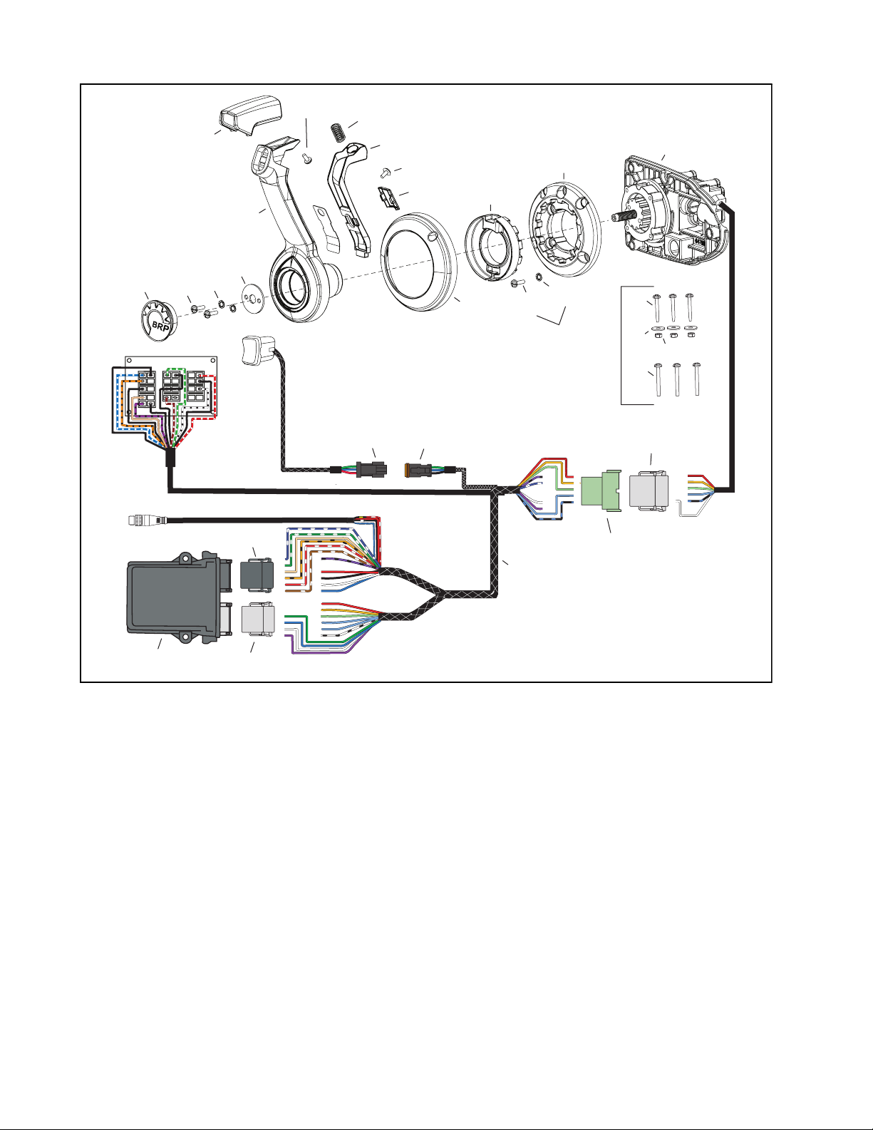
ICON CONCEALED SIDE MOUNT REMOTE CONTROL
27
RPM NEUTRAL
26
START/
STOP
17
25
44,45
28
46
16
24
18
20
29,30, 31
19
21
37,38,39
22
15
23
14
1
11
13
12
3
2
4
5
6
7,8,9,10
12
1
12
2
11
3
10
9
8
7
P-3
4
5
6
1
11
2
10
3
P-4
9
4
8
5
7
6
47
40,42,43
P-2
P-1
41,42,43
7
33,34,35,36
6
8
5
9
4
10
3
11
2
12
1
12
1
11
2
10
3
9
4
8
5
7
6
32
EPC4406
2 of 14

ICON CONCEALED SIDE MOUNT REMOTE CONTROL
y
p
p
g
g
pping
plug
g
g
plug
plug
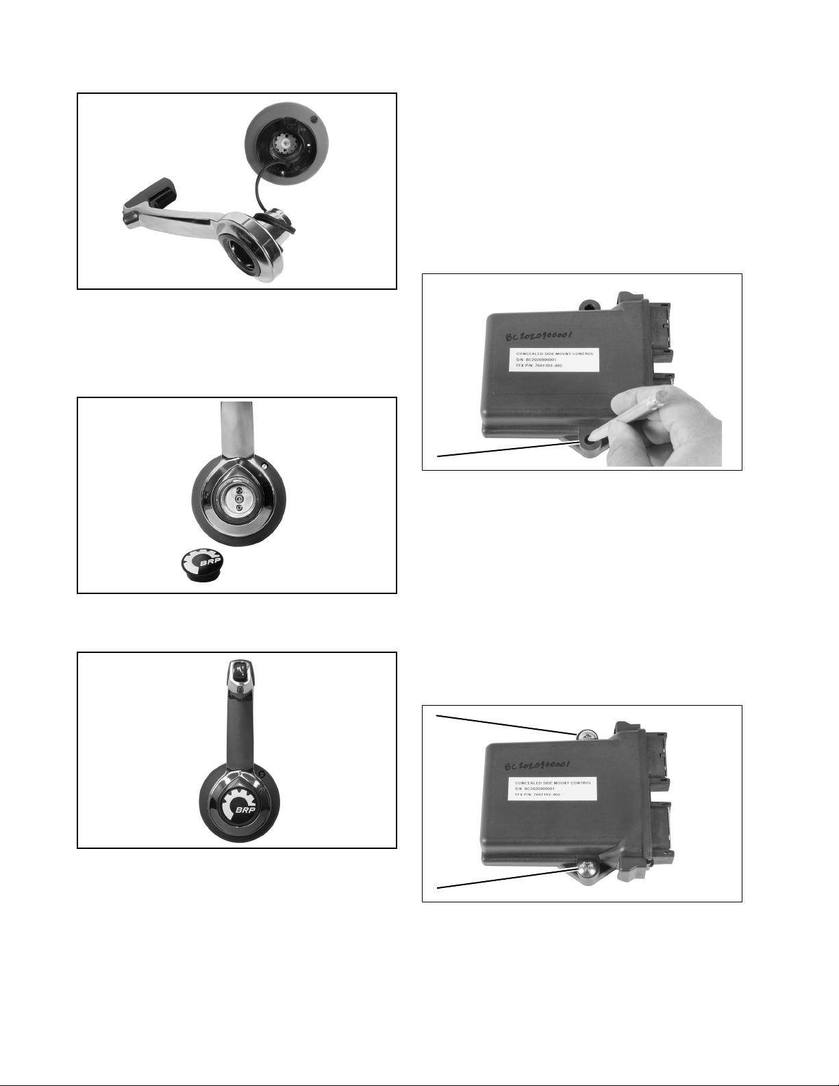
Ref P/N Name of Part QtyRef P/N Name of Part Qt
1 765412 CONTROL, Concealed Side Mount 1 28 5007485 **TRIM & TILT Switch 1
2 764610 *HARDWARE KIT, Installation 1 29 514686 ***CONNECTOR, 3
3 N/A **SCREW, 1/4x20 330512682***LOCK WEDGE, 3
4 N/A **WASHER, Mountin
5 N/A **LOCKNUT, Mountin
6 N/A **SCREW, #12 self ta
7 3011715 *CONNECTOR, 12 Socket
331 514679 ***TERMINAL, pin 3
332 765411 HARNESS, Remote Control 1
3333011717 *CONNECTOR, 12 pin rcpt1
1 3 4 3011718 *LOCKWEDGE, 12 pin rcpt1
83011714 *TERMINAL, Socket 6 35 3 011711 *TERMINAL, Pin 9
9514858 *SEAL, Plu
10 3 011716 *LOCKWEDGE, 12 Socket
6 3 6514858 *SEAL, Plu
1 3 7514685 *CONNECTOR, 3 Socket plug (Trim/Tilt)1
11 764606 *MOUNTING BASE 1 38 514681 *LOCKWEDGE, 3 Socket
12 765641 *RETAINER KIT 1 39514680 *TERMINAL, Socket 3
13 N/A **WASHER 4 40 - *CONNECTOR, 12 Socket plug (Black) 1
14 N/A **SCREW 4 41 - *CONNECTOR, 12 Socket plug (Gray) 1
15 764605 *CONTROL COVER 1 42 - *LOCKWEDGE, 12 Socket plug 2
16 764601 *CONTROL LEVER Assy 1 43 - *TERMINAL, Socket 21
17 764602 **GRIP KIT 1 44 765355 *CONNECTOR, Switch Panel 3
18 N/A ***SCREW (M5 x 0.8 x 10) 1 45 365356 *TERMINAL 10
19 764603 ** NEUTRAL LEVER KIT 1 46 765378 SWITCH KIT, Start/Stop, Neutral, RPM 1
20 N/A ***SPRING 1 - - (see R igging/Switch Kits - ICON)
21 N/A ***SCREW (M5 x 0.8 x 10) 1 47 765413 CONTROL MODULE, ICON 1
22 N/A ***CAP, Lock holder 1
23 N/A ***LOCK HOLDER 1
24 764604 ***RETAINER KIT, Throttle arm 1
25 N/A ****WASHER 2
26 N/A ****SCREW (M6 x 1.0 x 18) 2
NS
NS
NS
NS
NS
- *HARDWARE KIT, Control Module 1
- **SCREW, Module mounting (1/4x20) 2
- **WASHER, Mounting 2
- **LOCKNUT, Mounting 2
- **SCREW, #12 self tapping 2
27 353627 **RELEASE BUTTON (Cover) 1
in 1
in 1
3
1
3 of 14
INSTALLATION PROCEDURE
Refer to the ICON System Quick Connection
Guide, P/N 765409 for ICON System Diagram.
Disconnect the battery cables at the battery.
part of the boat throughout the control handle
travel.
NEUTRAL
FWD
15°
REV
15°
Test remote control operation after installation is
complete.
WARNING
Failure to properly install and test remote
control operation may result in remote
control malfunction and the loss of boat
control.
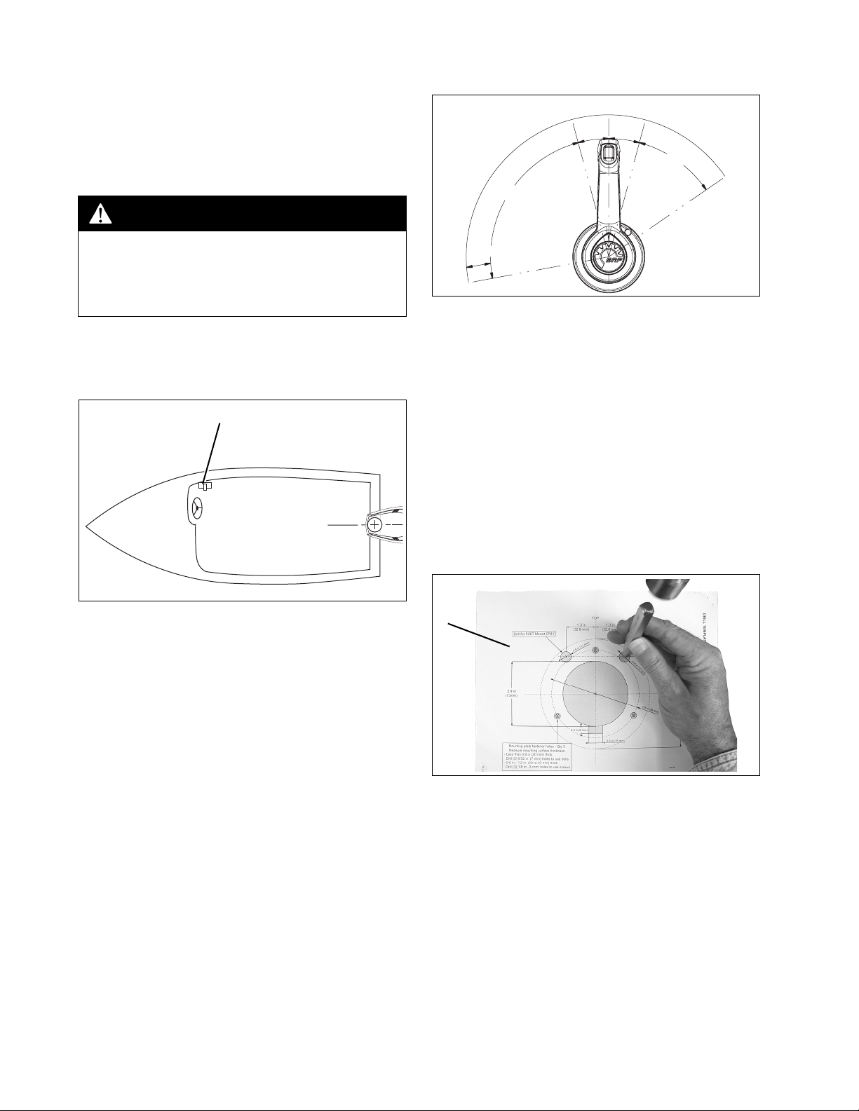
Mounting Location
Select an appropriate location based on the boat
configuration.
1
40.5°
85.5°
4 in (102 mm)
007973
There must be sufficient clear space behind the
control for the housing and cable routing.
Mounting Holes
Refer to ICON CONCEALED SIDE MOUNT
REMOTE CONTROL - DRILL TEMPLATE on
page 13.
IMPORTANT: Make sure the mounting location
has all the required clearances before drilling or
cutting.
Position template. Use center punch and mark
the centers of drill locations.
1. Side console 006152A
IMPORTANT: The mounting location must be a
flat surface and must be strong enough to provide a rigid support. Strengthen mounting surface as necessary. Remote control cannot be
installed if thickness of mounting surface exceeds 1.2 in. (30 mm).
Refer to ICON CONCEALED SIDE MOUNT
REMOTE CONTROL PROFILE DRAWING on
page 11.
Place remote control at proposed location and
check clearance around remote control handle at
full throttle in FORWARD and then at full throttle
in REVERSE. There must be at least 4 in. (102
mm) of clearance between the handle and any
1
1. Template 006338
Cut along the outer line of shaded area. Use
appropriate cutting tools. A 2 7/8 in.(73mm) hole
saw can be used for main through hole.
4 of 14
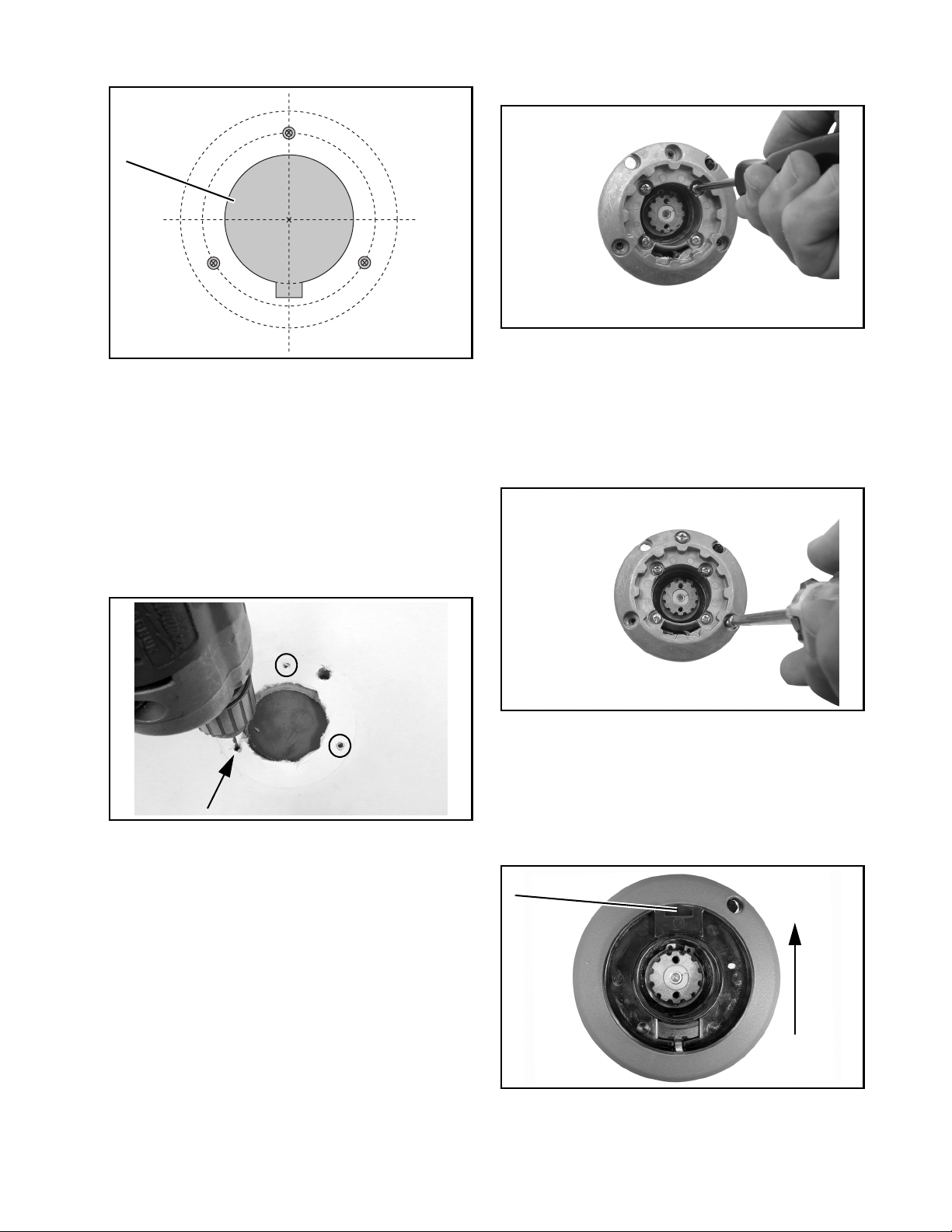
Notch bottom of hole for trim and tilt wiring.
1
control. Install four washers and screws and
tighten screws to 35 in./lbs.(4 N·m).
006340
1. Shaded area 006303
Select proper fasteners and drill bit size.
Determine thickness of mounting surface.
• Less than 0.8 in. (20 mm) thickness: Drill
three (3) 9/32 in. (7 mm) diameter holes to
use 8 mm bolts and nuts and washers provided.
• 0.8 in. - 1.2 in. (20 - 30mm) thickness: Drill
three (3) 1/8 in. (3 mm) holes to use screws
provided.
Drill three holes at mounting hole locations.
Align mounting plate with holes and secure to
mounting surface. Use bolts and nuts if surface
thickness is less than 0.8 in. (20mm) thick and
screws for surface thicknesses between 0.8
(20mm) and 1.2 in. (30mm) thick. Tighten screws
or bolts and nuts to 53-71 in./lbs.(6-8 N·m).
006341
IMPORTANT: Make sure remote control assembly is secure and does not move during operation.
006339
Mounting Control
Position remote control behind mounting
surface. Align mounting plate with remote
Position lock ring in mounting plate. Orient notch
for neutral lock lever UP as shown.
1
UP
1. Notch, lock ring 006374
5 of 14
Route trim/tilt switch wiring. Make two (2) loops
of trim wire around lever as shown
006349
Position remote control lever on splines of
remote control. Install retaining washer and
screws and washers to secure lever to output
shaft of remote control.
Mounting Control Module
Select an appropriate mounting location within
within 30 in. (76 cm) of the remote control due to
wire harness length.
The mounting location must provide:
• protection from the weather
• access for cable connections and wiring
• a flat surface which is rigid enough to prevent
control module movement
Position the control module. Mark mounting tabs
to install control module.
1
1. Mounting tab 007963
Install cover.
006351
006352
Select proper fasteners and drill bit size.
Determine thickness of mounting surface.
• Less than 0.8 in. (20 mm) thickness: Drill two
(2) 9/32 in. (7 mm) diameter holes to use
8 mm bolts and nuts and washers provided.
• 0.8 in. - 1.2 in. (20 - 30mm) thickness: Drill
two (2) 1/8 in. (3 mm) holes to use screws
provided.
Install control module and secure with two
screws or bolts and nuts. Tighten screws or bolts
and nuts to 53-71 in./lbs.(6-8 N·m).
1
1
1. Screws 007964
6 of 14
ICON Network Buss Cables
ICON network buss cables use a proprietary
6-pin threaded, Molex-type connector.
1. ICON buss cable connectors 007882
To assemble the connectors:
• Use the large tabs and small tabs to carefully
align buss cable connectors.
• Carefully align pins and sockets of connectors. Do NOT force connectors together.
• Tighten locking rings of buss connectors finger tight. Do NOT use locking rings to force
connectors together.
1
IMPORTANT: Do not force connectors or lock-
ing rings. Properly aligned connectors assemble
easily.
Do not use Electrical Grease on ICON buss
cable connectors.
2
1. Large tabs
2. Small tabs
Do not rotate connectors until they align. This
could result in a mismatched connection. It is
possible for each pin to enter a socket even if the
tabs are misaligned. Look at the tabs to ensure
connector alignment prior to making the
connection.
007883
7 of 14
ICON Concealed Side Mount Remote Control Connections
Connect remote control buss cable to ICON hub. If the installation requires a buss cable extension,
use no more than one extension. Connect P-1 and P-2 Deutsch connectors from harness to Control
Module. Push connectors together until latched. Connect P-3 Deutsch connector from harness to P-4
Deutsch connector of remote control. Push connectors together until latched. Apply a light coat of
Electrical Grease onto the seal of the Deutsch connector for the trim and tilt switch. Push connectors
together until latched.
RPM NEUTRAL
M
9
B
A
M
START/
STOP
10
4
3
1
P-2
1
2
P-1
3
2
4
5
P-3
A B C
8
7
3
P-4
A B C
6
2. Deutsch connector, P-1 from harness to control module
3. Deutsch connector, P-2 from harness to control module
4. Control module
5. Deutsch connector, P-3 from harness to remote control
6. Deutsch connector, P-4 from remote control to harness
7. Seal, Deutsch connector
8. Deutsch connector, trim and tilt
9. Buss cable, master power/key switch to ICON hub
10. Network power cable to battery
0079741. Buss cable, remote control to ICON hub
Check operation and movement of control lever. Make sure remote control shift and throttle functions
operate smoothly. Refer to REMOTE CONTROL OPERATION TESTS on page 9.
8 of 14
Control Lever Throttle Friction Adjustment
Try to restart the outboard. Outboard should not
start.
Check control lever friction. When properly
adjusted, the control lever should have low
friction to allow easy movement in FORWARD
throttle range, and not allow vibration to change
throttle setting.
Remove the cover from the remote control lever.
Use a 5/32 in. (4 mm) hex tool to adjust friction
adjustment screw. Turn adjustment screw
clockwise to increase the friction or
counterclockwise to reduce the friction.
2
1
1. Cover
2. Throttle friction adjustment screw
006351A
Shift into NEUTRAL and restart outboard.
Shift into REVERSE gear. Turn outboard OFF
while remote control is in REVERSE.
Try to restart the outboard. Outboard should not
start.
Emergency Stop Test
Check emergency stop function. Push clip of
emergency stop lanyard onto master power
switch/key switch.
Start the outboard(s). Refer to ICON User’s
Guide.
RUN
OFF
1
REMOTE CONTROL OPERATION TESTS
NOTICE
water supply to the outboard’s cooling system. Cooling system and/or powerhead damage could occur. Be sure the water intake
screens are below the water surface.
DO NOT run outboard without a
Check Start in Gear Protection
WARNING
Make certain starter will not operate when
the outboard is in gear. The start-in-gear
prevention feature is required by the
United States Coast Guard to help prevent
injuries.
Refer to the current Evinrude ICON Concealed
Side Mount Remote Control User’s Guide or
outboard’s operator’s guide for start procedure
and remote control operation.
Start the outboard and shift into FORWARD
gear.
1. Clip of emergency stop lanyard 007895
1
1
2
1. Clip of emergency stop lanyard 007896
With outboard(s) running, remove emergency
stop lanyard. Outboard must STOP. If outboard
does not stop, check master power/key switch
and wiring. Repair as needed.
Reinstall clip on master power/key switch.
Turn outboard OFF while remote control is in
FORWARD.
9 of 14
 Loading...