

Page 1
Main Menu
Page 2

Page 3

BRP US Inc.
Technical Publications
250 Sea Horse Drive
Waukegan, Illinois 60085 United States
† AMP, Superseal 1.5, Super Seal, Power Timer, and Pro-Crimper II
are registered trademarks of Tyco International, Ltd.
† Amphenol is a registered trademark of The Amphenol Corporation.
† Champion is a registered trademark of Federal-Mogul Corporation.
† Deutsch is a registered trademark of The Deutsch Company.
† Dexron is a registered trademark of The General Motors Corporation.
† Fluke is a registered trademark of The Fluke Corporation
† GE is a registered trademark of The General Electric Company.
† GM is a registered trademark of The General Motors Corporation.
† Locquic and Loctite are registered trademarks of The Henkel Group.
† Lubriplate is a registered trademark of Fiske Brothers Refining Company.
† NMEA is a registered trademark of the National Marine Electronics Association.
† Oetiker is a registered trademark of Hans Oetiker AG Maschinen.
† Packard is a registered trademark of Delphi Automotive Systems.
† Permatex is a registered trademark of Permatex.
† STP is a registered trademark of STP Products Company.
† Snap-on is a registered trademark of Snap-on Technologies, Inc.
The following trademarks are the property of BRP US Inc. or its affiliates:
Evinrude
Johnson
Evinrude
®
®
®
E-TEC
®
Nut Lock™
Screw Lock™
Ultra Lock™
FasTrak™ Gel-Seal II™
S.A.F.E.™ Moly Lube™
SystemCheck™
Triple-Guard
®
Grease
I-Command™ DPL™ Lubricant
Evinrude
Evinrude
Evinrude
®
/ Johnson ® XD30™ Outboard Oil 2+4 ® Fuel Conditioner
®
/ Johnson ® XD50™ Outboard Oil
®
/ Johnson ® XD100™ Outboard Oil
Carbon Guard™
HPF XR™ Gearcase Lubricant
Twist Grip™
Printed in the United States.
© 2008 BRP US Inc. All rights reserved.
TM, ® Trademarks and registered trademarks of Bombardier Recreational Products Inc. or its affiliates.
Page 4

TABLE
OF
CONTENTS
INTRODUCTION . . . . . . . . . . . . . . . . . . . . . . . . . . . . . . . . . . . 3
1 SPECIAL TOOLS . . . . . . . . . . . . . . . . . . . . . . . . . . . . . . 15
2 INSTALLATION AND PREDELIVERY . . . . . . . . . . . . . . 27
3 MAINTENANCE . . . . . . . . . . . . . . . . . . . . . . . . . . . . . . . 73
4 ENGINE COVER SERVICE . . . . . . . . . . . . . . . . . . . . . . 89
5 ENGINE MANAGEMENT MODULE (EMM) . . . . . . . . . . 93
6 SYSTEM ANALYSIS . . . . . . . . . . . . . . . . . . . . . . . . . . . 111
7 ELECTRICAL AND IGNITION . . . . . . . . . . . . . . . . . . . . 125
8 FUEL SYSTEM . . . . . . . . . . . . . . . . . . . . . . . . . . . . . . . 165
9 OILING SYSTEM . . . . . . . . . . . . . . . . . . . . . . . . . . . . . 189
10 COOLING SYSTEM . . . . . . . . . . . . . . . . . . . . . . . . . . . 207
11 POWERHEAD . . . . . . . . . . . . . . . . . . . . . . . . . . . . . . . . 217
12 MIDSECTION . . . . . . . . . . . . . . . . . . . . . . . . . . . . . . . . 259
13 GEARCASE . . . . . . . . . . . . . . . . . . . . . . . . . . . . . . . . . 281
GEARCASE – STANDARD ROTATION . . . . . . . . . . . . 295
GEARCASE – COUNTER ROTATION . . . . . . . . . . . . . 317
14 TRIM AND TILT . . . . . . . . . . . . . . . . . . . . . . . . . . . . . . . 329
SAFETY . . . . . . . . . . . . . . . . . . . . . . . . . . . . . . . . . . . . . . . S–1
INDEX . . . . . . . . . . . . . . . . . . . . . . . . . . . . . . . . . . . . . . . . . .I–1
TROUBLE CHECK CHART . . . . . . . . . . . . . . . . . . . . . . . . T–1
DIAGRAMS
EMM SERVICE CODE CHART
2
Page 5

INTRODUCTION
INTRODUCTION
CONTENTS
ABBREVIATIONS USED IN THIS MANUAL . . . . . . . . . . . . . . . . . . . . . . . . . . . . . . . . . . . . . . . . . . . . . . . .6
UNITS OF MEASUREMENT . . . . . . . . . . . . . . . . . . . . . . . . . . . . . . . . . . . . . . . . . . . . . . . . . . . . . . . . . . . .6
LIST OF ABBREVIATIONS . . . . . . . . . . . . . . . . . . . . . . . . . . . . . . . . . . . . . . . . . . . . . . . . . . . . . . . . . . . . .6
ENGINE EMISSIONS INFORMATION . . . . . . . . . . . . . . . . . . . . . . . . . . . . . . . . . . . . . . . . . . . . . . . . . . . . .7
MANUFACTURER’S RESPONSIBILITY . . . . . . . . . . . . . . . . . . . . . . . . . . . . . . . . . . . . . . . . . . . . . . . . . . . .7
DEALER’S RESPONSIBILITY . . . . . . . . . . . . . . . . . . . . . . . . . . . . . . . . . . . . . . . . . . . . . . . . . . . . . . . . . . .7
OWNER’S RESPONSIBILITY . . . . . . . . . . . . . . . . . . . . . . . . . . . . . . . . . . . . . . . . . . . . . . . . . . . . . . . . . . .7
EPA EMISSION REGULATIONS . . . . . . . . . . . . . . . . . . . . . . . . . . . . . . . . . . . . . . . . . . . . . . . . . . . . . . . . .7
MODEL DESIGNATION . . . . . . . . . . . . . . . . . . . . . . . . . . . . . . . . . . . . . . . . . . . . . . . . . . . . . . . . . . . . . . . .8
MODELS COVERED IN THIS MANUAL . . . . . . . . . . . . . . . . . . . . . . . . . . . . . . . . . . . . . . . . . . . . . . . . . . .9
IDENTIFYING MODEL AND SERIAL NUMBERS . . . . . . . . . . . . . . . . . . . . . . . . . . . . . . . . . . . . . . . . . . . . . .9
SERVICE SPECIFICATIONS . . . . . . . . . . . . . . . . . . . . . . . . . . . . . . . . . . . . . . . . . . . . . . . . . . . . . . . . . . .10
STANDARD TORQUE SPECIFICATIONS . . . . . . . . . . . . . . . . . . . . . . . . . . . . . . . . . . . . . . . . . . . . . . . .14
PRODUCT REFERENCE AND ILLUSTRATIONS . . . . . . . . . . . . . . . . . . . . . . . . . . . . . . . . . . . . . . . . . . .14
3
Page 6
SAFETY INFORMATION
Before working on any part of the outboard, read the SAFETY section at the end of this manual.
This manual is written for qualified, factory-trained
technicians who are already familiar with the use
of Evinrude
ual is not a substitute for work experience. It is an
organized guide for reference, repair, and maintenance of the outboard(s).
This manual uses the following signal words identifying important safety messages.
®
/Johnson® Special Tools. This man-
DANGER
Indicates an imminently hazardous situation which, if not avoided, WILL result in
death or serious injury.
WARNING
Indicates a potentially hazardous situation
which, if not avoided, CAN result in severe
injury or death.
Always follow common shop safety practices. If
you have not had training related to common shop
safety practices, you should do so to protect yourself, as well as the people around you.
It is understood that this manual may be translated into other languages. In the event of any discrepancy, the English version shall prevail.
To reduce the risk of personal injury, safety warnings are provided at appropriate times throughout
the manual.
DO NOT make any repairs until you have read the
instructions and checked the pictures relating to
the repairs.
Be careful, and never rush or guess a service procedure. Human error is caused by many factors:
carelessness, fatigue, overload, preoccupation,
unfamiliarity with the product, and drugs and alcohol use, to name a few. Damage to a boat and
outboard can be fixed in a short period of time, but
injury or death has a lasting effect.
CAUTION
Indicates a potentially hazardous situation
which, if not avoided, MAY result in minor
or moderate personal injury or property
damage. It also may be used to alert
against unsafe practices.
IMPORTANT: Identifies information that will
help prevent damage to machinery and appears
next to information that controls correct assembly
and operation of the product.
These safety notices mean:
ATTENTION!
BECOME ALERT!
YOUR SAFETY IS INVOLVED!
When replacement parts are required, use
Evinrude/Johnson Genuine Parts or parts with
equivalent characteristics, including type, strength
and material. Using substandard parts could
result in injury or product malfunction.
Torque wrench tightening specifications must be
strictly followed. Replace any locking fastener
(locknut or patch screw) if its locking feature
becomes weak. Definite resistance to turning
must be felt when reusing a locking fastener. If
replacement is specified or required because the
locking fastener has become weak, use only
authorized Evinrude/Johnson Genuine Parts.
If you use procedures or service tools that are not
recommended in this manual, YOU ALONE must
decide if your actions might injure people or damage the outboard.
Page 7

DANGER
Contact with a rotating propeller is likely to result in serious injury or death. Assure the
engine and prop area is clear of people and objects before starting engine or operating boat.
Do not allow anyone near a propeller, even when the engine is off. Blades can be sharp and
the propeller can continue to turn even after the engine is off. Remove propeller before servicing and when running the outboard on a flushing device.
DO NOT run the engine indoors or without adequate ventilation or permit exhaust fumes to
accumulate in confined areas. Engine exhaust contains carbon monoxide which, if inhaled,
can cause serious brain damage or death.
WARNING
Wear safety glasses to avoid personal injury, and set compressed air to less than 25 psi (172
kPa).
The motor cover and flywheel cover are machinery guards. Use caution when conducting
tests on running outboards. DO NOT wear jewelry or loose clothing. Keep hair, hands, and
clothing away from rotating parts.
During service, the outboard may drop unexpectedly. Avoid personal injury; always support
the outboard’s weight with a suitable hoist or the tilt support bracket during service.
To prevent accidental starting while servicing, disconnect the battery cables at the battery.
Twist and remove all spark plug leads.
The electrical system presents a serious shock hazard. DO NOT handle prima ry or secondary
ignition components while outboard is running or flywheel is turning.
Gasoline is extremely flammable and highly explosive under certain conditions. Use caution
when working on any part of the fuel system.
Protect against hazardous fuel spray. Before starting any fuel system service, carefully
relieve fuel system pressure.
Do not smoke, or allow open flames or sparks, or use electrical devices such as cellular
phones in the vicinity of a fuel leak or while fueling.
Keep all electrical connections clean, tight, and insulated to prevent shorting or arcing and
causing an explosion.
Always work in a well ventilated area.
Replace any locking fastener (locknut or patch screw) if its locking feature becomes weak.
Definite resistance to tightening must be felt when reusing a locking fastener. If replacement
is indicated, use only authorized replacement or equivalent.
Page 8

INTRODUCTION
ABBREVIATIONS USED IN THIS MANUAL
ABBREVIATIONS USED IN THIS MANUAL
Units of Measurement List of Abbreviations
A Amperes
amp-hr Ampere hour
fl. oz. fluid ounce
ft. lbs. foot pounds
HP horsepower
in. inch
in. Hg inches of mercury
in. lbs. inch pounds
kPa kilopascals
ml milliliter
mm millimeter
N·m Newton meter
P/N part number
psi pounds per square inch
RPM revolutions per minute
°C degrees Celsius
°F degrees Fahrenheit
ms milliseconds
µs microseconds
Ω Ohms
VVolts
VAC Volts Alternating Current
VDC Volts Direct Current
ABYC American Boat & Yacht Council
ATDC after top dead center
AT air temperature sensor
BPS barometric pressure sensor
BTDC before top dead center
CCA cold cranking amps
CPS crankshaft position sensor
EMM Engine Management Module
ICOMIA International Council of Marine
Industry Associations
MCA marine cranking amps
MWS modular wiring system
NMEA National Marine Electronics Assoc.
NTC negative temperature coefficient
PTC positive temperature coefficient
ROM read only memory
S.A.F.E.™ speed adjusting failsafe electronics
SAC start assist circuit
SAE Society of Automotive Engineers
SYNC synchronization
TDC top dead center
TPS throttle position sensor
WOT wide open throttle
WTS water temperature sensor
6
Page 9

INTRODUCTION
ENGINE EMISSIONS INFORMATION
ENGINE EMISSIONS
INFORMATION
Maintenance, replacement, or repair of the
emission control devices and systems may be
performed by any marine SI (spark ignition)
engine repair establishment or individual.
Manufacturer’s Responsibility
Beginning with 1999 model year outboards, manufacturers of marine outboards must determine
the exhaust emission levels for each outboard
horsepower family and certify these outboards
with the United States of America Environmental
Protection Agency (EPA). An emissions control
information label, showing emission levels and
outboard specifications, must be placed on each
outboard at the time of manufacture.
Dealer’s Responsibility
When performing service on all 1999 and more
recent Evinrude/Johnson outboards that carry an
emissions control information label, adjustments
must be kept within published factory specifications.
Replacement or repair of any emission related
component must be executed in a manner that
maintains emission levels within the prescribed
certification standards.
Dealers are not to modify the outboard in any
manner that would alter the horsepower or allow
emission levels to exceed their predetermined
factory specifications.
Exceptions include manufacturer’s prescribed
changes, such as altitude adjustments, for example.
Owner’s Responsibility
The owner/operator is required to have outboard
maintenance performed to maintain emission levels within prescribed certification standards.
The owner/operator is not to, and should not allow
anyone to, modify the outboard in any manner
that would alter the horsepower or allow emissions levels to exceed their predetermined factory
specifications.
Tampering with the fuel system to change horsepower or modify emission levels beyond factory
settings or specifications will void the product warranty.
EPA Emission Regulations
All new 1999 and more recent Evinrude/Johnson
outboards are certified to the EPA as conforming
to the requirements of the regulations for the control of air pollution from new watercraft marine
spark ignition outboards. This certification is contingent on certain adjustments being set to factory
standards. For this reason, the factory procedure
for servicing the product must be strictly followed
and, whenever practical, returned to the original
intent of the design. The responsibilities listed
above are general and in no way a complete listing of the rules and regulations pertaining to the
EPA requirements on exhaust emissions for
marine products. For more detailed information on
this subject, you may contact the following locations:
VIA U.S. POSTAL SERVICE:
Office of Mobile Sources
Engine Programs and Compliance Division
Engine Compliance Programs Group (6403J)
401 M St. NW
Washington, DC 20460
VIA EXPRESS or COURIER MAIL:
Office of Mobile Sources
Engine Programs and Compliance Division
Engine Compliance Programs Group (6403J)
501 3rd St. NW
Washington, DC 20001
EPA INTERNET WEB SITE:
www.epa.gov
7
Page 10
INTRODUCTION
MODEL DESIGNATION
MODEL DESIGNATION
PREFIX
STYLE:
J = Johnson
E = Evinrude
HORSEPOWER
LENGTH:
= 15” Std.
L = 20” Long
Y = 22.5” Special
X = 25” X-long
Z = 30” XX-long
MODEL RUN
or SUFFIX
B E 200 DP X SE E
DESIGN FEATURES:
AP = Advanced Propulsion
B = Blue Paint
C = Counter Rotation
D = Evinrude E-TEC™
E = Electric Start w/Remote Steering
F = Direct-Injection
G = Graphite Paint
H = High Output
J = Jet Drive
M = Military
P = Power Trim and Tilt
R = Rope Start w/Tiller Steering
S = Saltwater Edition
T = Tiller Steering
TE = Tiller Electric
V = White Paint
W = Commercial Model
MODEL YR:
I= 1
N= 2
T= 3
R= 4
O= 5
D= 6
U= 7
C= 8
E= 9
S= 0
Ex: SE = 2009
8
Page 11
INTRODUCTION
MODELS COVERED IN THIS MANUAL
MODELS COVERED IN
THIS MANUAL
This manual covers service information on all
200.1 and 210 cubic inch, 90° V Evinrude E-TEC
models.
Model Shaft Color G earcase
E200DHLSEB 3.3 L 20” BL .54 L2
E200HSLSEA 3.3 L 20” WH .54 L2
E200HVLSEC 3.3 L 20” WH .54 M2
E200DHXSEA 3.3 L 25” WH .54 M2
E200HCXSEA 3.3 L 25” WH .54 M2 CR
E225DPLSEB 3.3 L 20” BL .54 M2
E225DHLSEB 3.3 L 20” BL .58 L2
E225HSLSEC 3.3 L 20” WH .58 L2
E225DHXSEM 3.3 L 25” BL .58 L2
E225DPXSEB 3.3 L 25” WH .54 M2
E225DCXSEB 3.3 L 25” WH .54 M2 CR
E225DPZSEB 3.3 L 30” WH .54 M2
E225DCZSEB 3.3 L 30” WH .54 M2 CR
E250DPLSEB 3.3 L 20” BL .54 M2
E250DPXSEB 3.3 L 25” WH .54 M2
E250DCXSEB 3.3 L 25” WH .54 M2 CR
E250DPZSEB 3.3 L 30” WH .54 M2
E250DCZSEB 3.3 L 30” WH .54 M2 CR
E250HSLSES 3.4 L 20” WH .58 L2
E250HSLSEF 3.4 L 20” WH .58 L2
E250DHLSEC 3.4 L 20” BL .58 L2
E250DHLSEF 3.4 L 20” BL .58 L2
E250DHXSEC 3.4 L 25” BL .58 L2
E250DHXSEF 3.4 L 25” BL .58 L2
E250HGLSES 3.4 L 20” SM .58 L2
E250HGLSEF 3.4 L 20” SM .58 L2
E250HGXSES 3.4 L 25” SM .58 L2
E250HGXSEF 3.4 L 25” SM .58 L2
E300DSLSES 3.4 L 20” WH .54 M2
E300DSLSEF 3.4 L 20” WH .54 M2
E300DPXSEC 3.4 L 25” WH .54 M2
E300DPXSEF 3.4 L 25” WH .54 M2
E300DPZSEC 3.4 L 30” WH .54 M2
E300DPZSEF 3.4 L 30” WH .54 M2
E300DCXSEC 3.4 L 25” WH .54 M2 CR
E300DCXSEF 3.4 L 25” WH .54 M2 CR
E300DCZSEC 3.4 L 30” WH .54 M2 CR
E300DCZSEF 3.4 L 30” WH .54 M2 CR
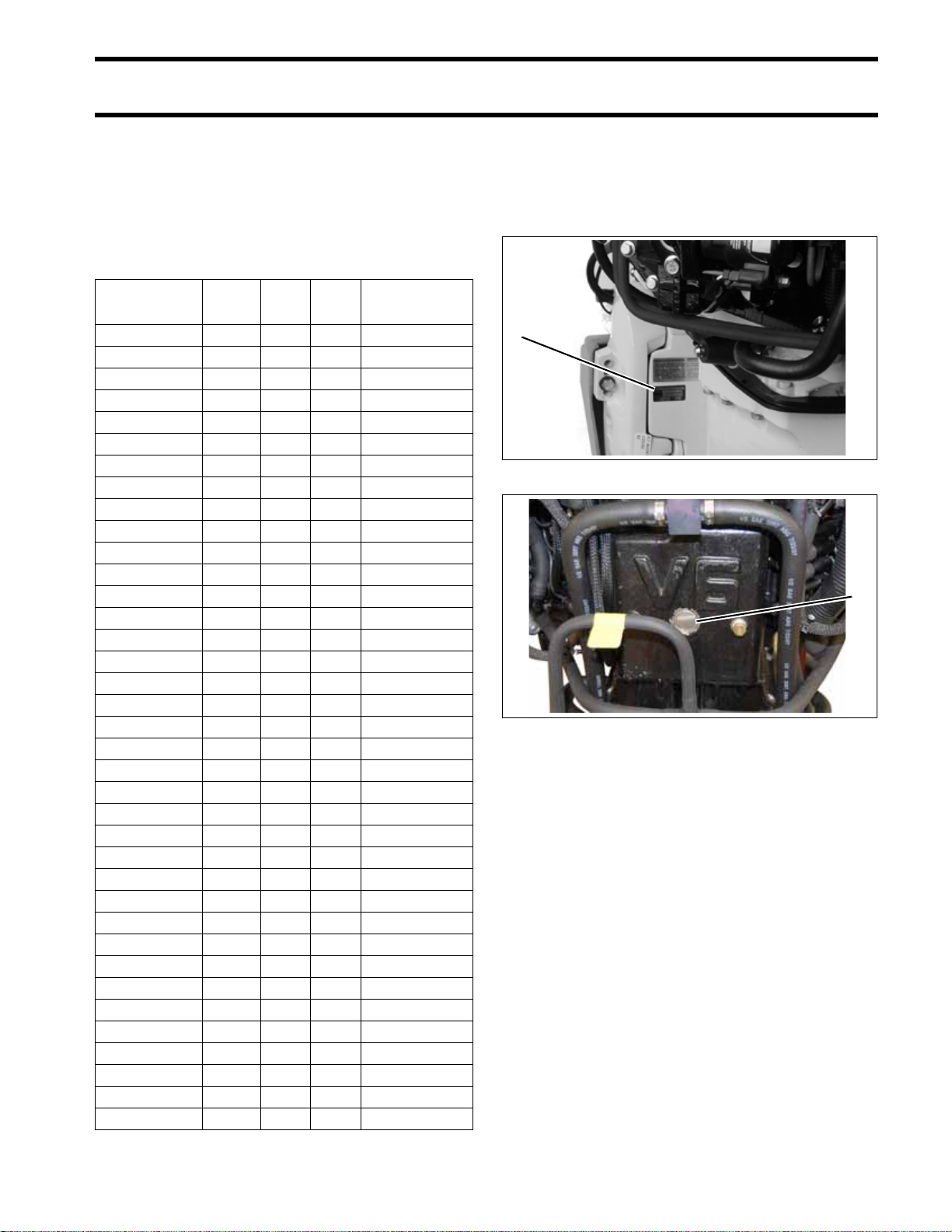
Identifying Model and Serial Numbers
Outboard model and serial numbers are located
on the swivel bracket and on the powerhead.
®
1
1. Model and serial number 000449
1
1. Serial number 006828
9
Page 12

INTRODUCTION
SERVICE SPECIFICATIONS
SERVICE SPECIFICATIONS
HP 200 225 250
Full Throttle
Operating Range
200 HP
Power
Idle RPM in Gear 500 ± 50
Test Propeller
Weight
(may vary depending
on model)
Lubrication
ENGINE
Minimum (High) Fuel Pressure
Minimum Fuel Lift Pump Pressure
FUEL
Maximum Fuel Inlet Vacuum 4 in. Hg. (13.5 kPa)
Engine Type 90° V 6-Cylinder Loop-Charged
Displacement
Bore 3.854 in (97.89 mm)
Stroke 2.858 in. (72.60 mm)
Standard Bore
Top Crankshaft Journal 1.6199 to 1.6204 in. (41.15 to 41.16 mm)
Center Crankshaft Journals 2.1870 to 2.1875 in. (55.55 to 55.56 mm)
Bottom Crankshaft Journal 1.5747 to 1.5752 in. (40.0 to 40.01 mm)
Rod Crankpin 1.4995 to 1.5000 in. (38.09 to 38.106 mm)
Piston Ring End Gap, Both 0.022 to 0.028 in. (0.57 to 0.72 mm)
Fuel/Oil Ratio EMM Controlled
Starting Enrichment EMM Controlled
Preferred Fuel Regular unleaded gasoline
Acceptable Fuel See Fuel Requirements on p. 58 for additional information.
@ IDLE RPM – 500 ± 50
@ IDLE RPM – 500 ± 50
Minimum Octane 87 AKI (R+M)/2 or 90 RON
Additives
(149 kw)
@ 5150 RPM
Standard Rotation Models: P/N 436080 or P/N 396277
Counter Rotation Models: P/N 436081 or P/N 398674
3.8535 to 3.8545 in. (97.87 to 97.90 mm)
To bore oversize, add piston oversize dimension to standard bore
2+4
Use of other additives may result in engine damage.
See Fuel Requirements on p. 58 for additional information.
4500–5800 RPM
225 HP
(168 kw)
@ 5150 RPM
20 in. (L) Models: 503 lbs. (228 kg)
25 in. (X) Models: 524 lbs. (238 kg)
30 in. (Z) Models: 530 lbs. (240 kg)
Evinrude/Johnson XD100 Oil
Refer to Oil Requirements on p. 59
200.1 cu. in. (3279 cm
22 to 28 psi (152 to 193 kPa)
3 psi (21 kPa)
®
Fuel Conditioner, Fuel System Cleaner
250 HP (187 kw)
3
)
@ 5150 RPM
10
Page 13

Minimum Battery
Requirements
Alternator Dual Voltage 50 Amp with Voltage Regulator and Battery Isolation
Tachometer Setting 6 pulse (12 pole)
ELECTRICAL
Charging Isolator Integral, Terminal on Engine Harness
Engine Fuse P/N 967545 – 10 A
Thermostat 143°F (62°C)
Maximum Temperature 190°F (88°C)
INTRODUCTION
SERVICE SPECIFICATIONS
HP 200 225 250
675 CCA (845 MCA); or
750 CCA (940 MCA) below 32°F (0°C)
(Use a 107 amp-hr battery for extreme applications.)
COOLING
Crankshaft Position Sensor Air Gap Fixed
IGNITION
GEARCASE
Water pressure 11 psi minimum @ 5000 RPM
Type Capacitor Discharge
Firing Order 1-2-3-4-5-6
Ignition Features EMM Controlled
RPM Limit 6050
Spark Plug
Gear Ratio
Lubricant HPF XR Gearcase Lubricant
Capacity
Shift Rod Height
Shift Cable Stroke 1.125 to 1.330 in. (28.6 to 33.8 mm) measured between NEUTRAL and FORWARD
Lubrication
Refer to Emission Control Information Label
†
Champion
“L2” Type Gearcase – 200 HP: 14:26 (.538) (1.86:1)
“L2” Type Gearcase – 225 HP: 14:24 (.583) (1.71:1)
“M2” Type – Counter Rotation: 35.8 fl. oz. (1060 ml)
20 in. (L) Models: 21 29/32 (556.25 mm) ± one-half turn
25 in. (X) Models: 26 29/32 (683.25 mm) ± one-half turn
30 in. (Z) Models: 31 29/32 (810.25 mm) ± one-half turn
QC8WEP @ 0.028 ± 0.003 in. (0.71 mm)
“M2” Type Gearca se: 13:24 (.542) (1.85:1)
Refer to GEARCASE TYPES on p. 285
“M2” Type Gearcase: 38.9 fl. oz. (1150 ml)
“L2” Type Gearcase: 32.5 fl. oz. (960 ml)
Refer to GEARCASE TYPES on p. 285
Power Trim/Tilt & Power Steering Fluid or
GM Dexron
†
II Automatic Transmission Fluid
Fluid Capacity 21 fl. oz. (622 ml)
Trim Range 0° to 21°
Tilt Range 22° to 75°
Tilt UP Stall Pressure 1500 psi (10342 kPa)
POWER TRIM/TILT
Tilt IN Stall Pressure 800 psi (5516 kPa)
11
Page 14

INTRODUCTION
SERVICE SPECIFICATIONS
HP 250 H 300
Full Throttle
Operating Range
Power
Idle RPM in Gear 500 ± 50
Test Propeller
Weight
(may vary depending
on model)
Lubrication
ENGINE
Minimum (High) Fuel Pressure
Minimum Fuel Lift Pump Pressure
FUEL
Maximum Fuel Inlet Vacuum 4 in. Hg. (13.5 kPa)
Engine Type 90° V 6-Cylinder Loop-Charged
Displacement 210.0 cu. in. (3441 cc)
Bore 3.854 in (97.89 mm)
Stroke 3.000 in. (76.20 mm)
Standard Bore
Top Crankshaft Journal 1.6199 to 1.6204 in. (41.15 to 41.16 mm)
Center Crankshaft Journals 2.1870 to 2.1875 in. (55.55 to 55.56 mm)
Bottom Crankshaft Journal 1.5747 to 1.5752 in. (40.0 to 40.01 mm)
Rod Crankpin 1.4995 to 1.5000 in. (38.09 to 38.106 mm)
Piston Ring End Gap, Both 0.022 to 0.028 in. (0.57 to 0.72 mm)
Fuel/Oil Ratio EMM Controlled
Starting Enrichment EMM Controlled
Preferred Fuel Regular unleaded gasoline
Acceptable Fuel See Fuel Requirements on p. 58 for additional information.
@ IDLE RPM – 500 ± 50
@ IDLE RPM – 500 ± 50
Minimum Octane 87 AKI (R+M)/2 or 90 RON
Additives
4500–6000 RPM 5000–6000 RPM
250 HP
(187 kw)
@ 5250 RPM
Standard Rotation Models: P/N 436080 or P/N 396277
Counter Rotation Models: P/N 436081 or P/N 398674
20 in. (L) Models: 507 lbs. (230 kg)
25 in. (X) Models: 528 lbs. (239 kg)
30 in. (Z) Models: 534 lbs. (242 kg)
Evinrude/Johnson XD100 Oil
Refer to Oil Requirements on p. 59
3.8535 to 3.8545 in. (97.87 to 97.90 mm)
To bore oversize, add piston oversize dimension to standard bore
22 to 28 psi (152 to 193 kPa)
3 psi (21 kPa)
®
Fuel Conditioner, Fuel System Cleaner
2+4
Use of other additives may result in engine damage.
See Fuel Requirements on p. 58 for additional information.
300 HP
(234 kw)
@ 5500 RPM
12
Page 15

Minimum Battery
Requirements
Alternator Dual Voltage 50 Amp with Voltage Regulator and Battery Isolation
Tachometer Setting 6 pulse (12 pole)
ELECTRICAL
Charging Isolator Integral, Terminal on Engine Harness
Engine Fuses P/N 967545 – 10 A
Thermostat 143°F (62°C)
Maximum Temperature 190°F (88°C)
INTRODUCTION
SERVICE SPECIFICATIONS
HP 250 H 300
675 CCA (845 MCA); or
750 CCA (940 MCA) below 32°F (0°C)
(Use a 107 amp-hr battery for extreme applications.)
COOLING
Crankshaft Position Sensor Air Gap Fixed
IGNITION
GEARCASE
Water pressure 11 psi minimum @ 5000 RPM
Type Capacitor Discharge
Firing Order 1-2-3-4-5-6
Ignition Features EMM Controlled
RPM Limit 6050
Spark Plug
Gear Ratio
Lubricant HPF XR Gearcase Lubricant
Capacity
Shift Rod Height
Shift Cable Stroke 1.125 to 1.330 in. (28.6 to 33.8 mm) measured between NEUTRAL and FORWARD
Lubrication
Refer to Emission Control Information Label
†
Champion
“M2” Type – Counter Rotation: 35.8 fl. oz. (1060 ml)
20 in. (L) Models: 21 29/32 (556.25 mm) ± one-half turn
25 in. (X) Models: 26 29/32 (683.25 mm) ± one-half turn
30 in. (Z) Models: 31 29/32 (810.25 mm) ± one-half turn
QC8WEP @ 0.028 ± 0.003 in. (0.71 mm)
“M2” Type Gearca se: 13:24 (.542) (1.85:1)
“L2” Type Gearcase: 14:24 (.583) (1.71:1)
Refer to GEARCASE TYPES on p. 285
“M2” Type Gearcase: 38.9 fl. oz. (1150 ml)
“L2” Type Gearcase: 32.5 fl. oz. (960 ml)
Refer to GEARCASE TYPES on p. 285
Power Trim/Tilt & Power Steering Fluid or
GM Dexron
†
II Automatic Transmission Fluid
Fluid Capacity 21 fl. oz. (622 ml)
Trim Range 0° to 21°
Tilt Range 22° to 75°
Tilt UP Stall Pressure 1500 psi (10342 kPa)
POWER TRIM/TILT
Tilt IN Stall Pressure 800 psi (5516 kPa)
13
Page 16
INTRODUCTION
STANDARD TORQUE SPECIFICATIONS
STANDARD TORQUE
SPECIFICATIONS
Size In. Lbs. Ft. Lbs. N·m
No. 6 7–10 0.58–0.83 0.8–1.1
No. 8 15–22 1.25–1.83 1.7–2.5
No. 10 24–36 2–3 2.7–4.0
No. 12 36–48 3–4 4.0–5.4
1/4 in. 60–84 5–7 7-9.5
5/16 in. 120–144 10–12 13.5–16.5
3/8 in. 216–240 18–20 24.5–27
7/16 in. 336–384 28–32 38–43.5
IMPORTANT: These values apply only when
a specific torque for a specific fastener is not
listed in the appropriate section. When tightening two or more screws on the same part, DO
NOT tighten screws completely, one at a time.
WARNING
PRODUCT REFERENCE AND ILLUSTRATIONS
BRP US Inc. reserves the right to make changes
at any time, without notice, in specifications and
models and also to discontinue models. The right
is also reserved to change any specifications or
parts, at any time, without incurring any obligation
to equip same on models manufactured prior to
date of such change. Specifications used are
based on the latest product information available
at the time of publication.
The continuing accuracy of this manual cannot be
guaranteed.
All photographs and illustrations used in this manual may not depict actual models or equipment,
but are intended as representative views for reference only.
Certain features or systems discussed in this
manual might not be found on all models in all
marketing areas.
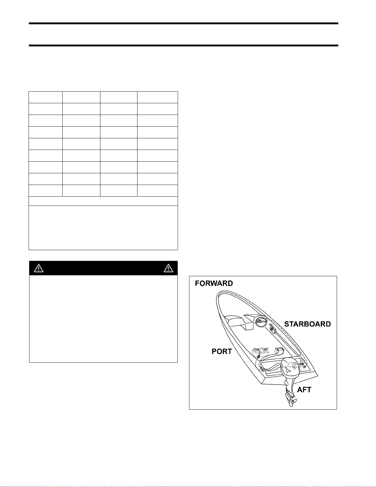
All service technicians must be familiar with nautical orientation. This manual often identifies parts
and procedures using these terms.
Torque wrench tightening specifications
must be strictly adhered to. Replace any
locking fastener (locknut or patch screw)
if its locking feature becomes weak. Definite resistance to turning must be felt
when reusing a locking fastener.
If replacement is specified or required
because the locking fastener has become
weak, use only authorized Evinrude/
Johnson Genuine Parts.
Nautical Orientation 006411
14
Page 17

SPECIAL TOOLS
SPECIAL TOOLS
TABLE OF CONTENTS
DIAGNOSTIC TOOLS . . . . . . . . . . . . . . . . . . . . . . . . . . . . . . . . . . . . . . . . . . . . . . . . . . . . . . . . . . . . . . . .16
UNIVERSAL TOOLS . . . . . . . . . . . . . . . . . . . . . . . . . . . . . . . . . . . . . . . . . . . . . . . . . . . . . . . . . . . . . . . . .16
ELECTRICAL / IGNITION TOOLS . . . . . . . . . . . . . . . . . . . . . . . . . . . . . . . . . . . . . . . . . . . . . . . . . . . . . . .18
FUEL /OIL SYSTEM TOOLS . . . . . . . . . . . . . . . . . . . . . . . . . . . . . . . . . . . . . . . . . . . . . . . . . . . . . . . . . . .19
POWERHEAD TOOLS . . . . . . . . . . . . . . . . . . . . . . . . . . . . . . . . . . . . . . . . . . . . . . . . . . . . . . . . . . . . . . . .19
GEARCASE TOOLS . . . . . . . . . . . . . . . . . . . . . . . . . . . . . . . . . . . . . . . . . . . . . . . . . . . . . . . . . . . . . . . . .20
TRIM AND TILT TOOLS . . . . . . . . . . . . . . . . . . . . . . . . . . . . . . . . . . . . . . . . . . . . . . . . . . . . . . . . . . . . . .23
SHOP AIDS . . . . . . . . . . . . . . . . . . . . . . . . . . . . . . . . . . . . . . . . . . . . . . . . . . . . . . . . . . . . . . . . . . . . . . . .24
1
15
Page 18
SPECIAL TOOLS
DIAGNOSTIC TOOLS
DIAGNOSTIC TOOLS
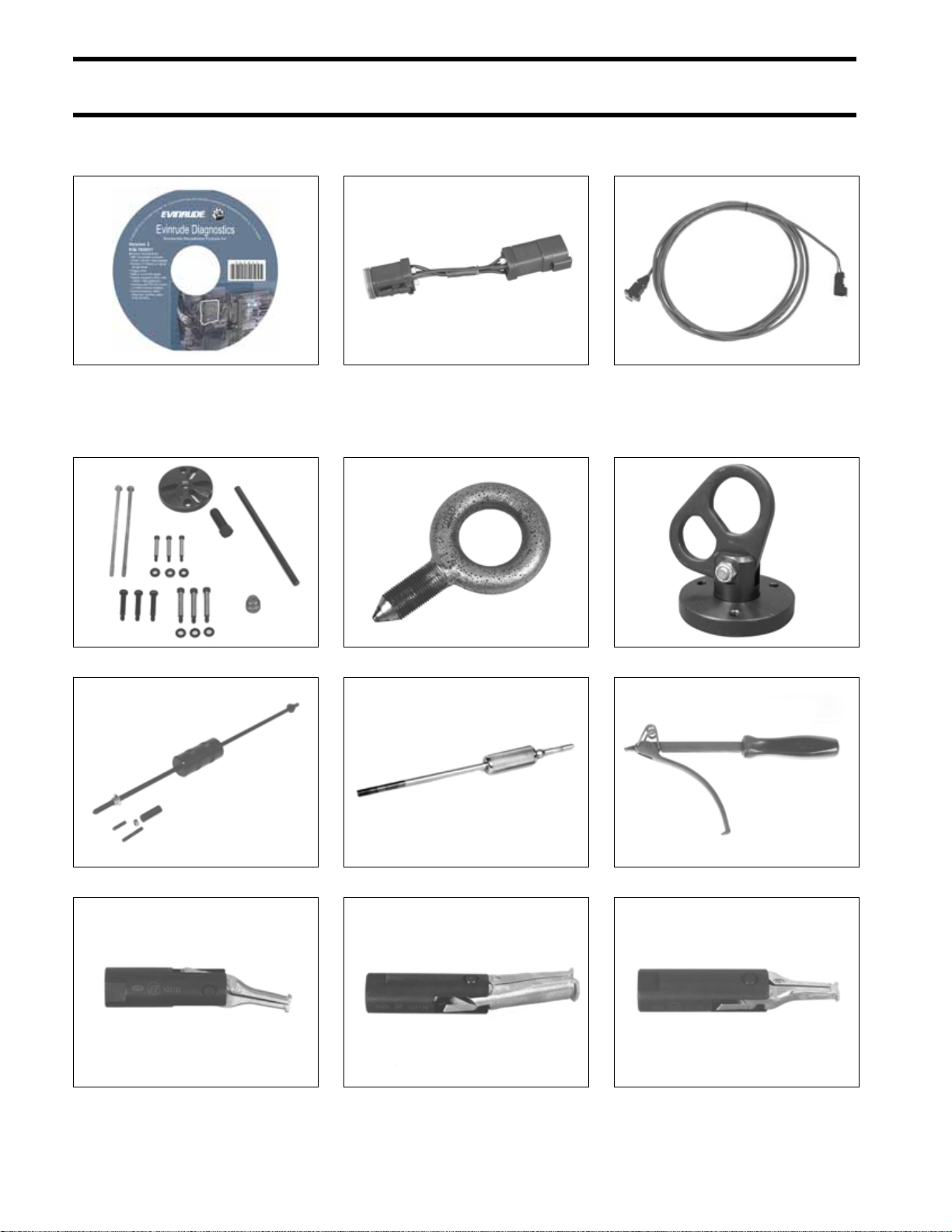
Diagnostic Software P/N 765011 765011 Bootstrap tool P/N 586551 002276 Interface cable P/N 437955 45583
UNIVERSAL TOOLS
Universal Puller Set P/N 378103 32885
Slide hammer P/N 391008 CO1577
Small puller jaws P/N 432131 23150
Lifting eye P/N 321537 23701
Slide hammer P/N 432128 15345
Large puller jaws P/N 432129 23148
Lifting ring assembly P/N 396748 000669
Flywheel holder P/N 771311 42938
Bearing puller jaws P/N 432130 23149
16
Page 19
SPECIAL TOOLS
UNIVERSAL TOOLS
1
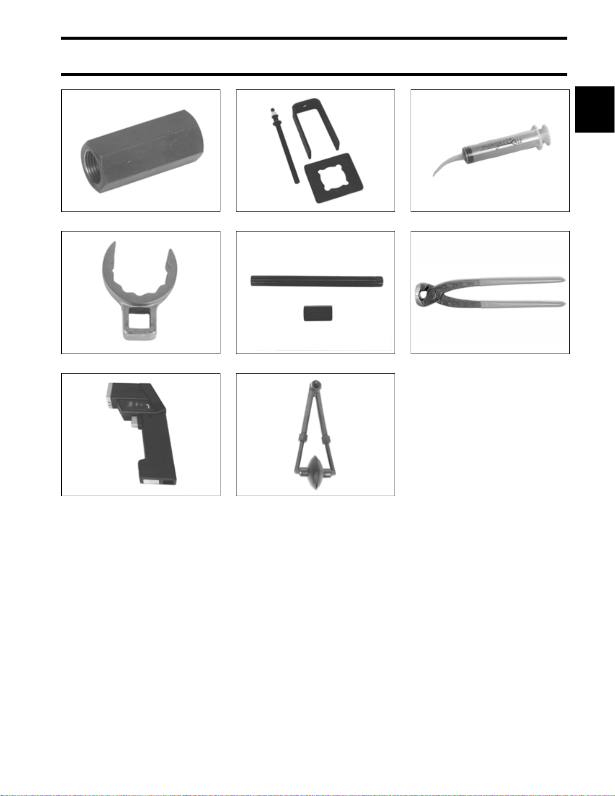
Slide hammer adapter P/N 390898 15356
Tilt tube nut wrench P/N 342680 46879
Temperature gun P/N 772018 45240
Puller Bridge – 432127 23146
Tilt tube service kit P/N 434523 33249
Fresh water flusher P/N 500542 50110
Syringe P/N 346936 50243
†
pincers, P/N 787145
Oetiker
001081
17
Page 20
SPECIAL TOOLS
ELECTRICAL / IGNITION TOOLS
ELECTRICAL / IGNITION TOOLS
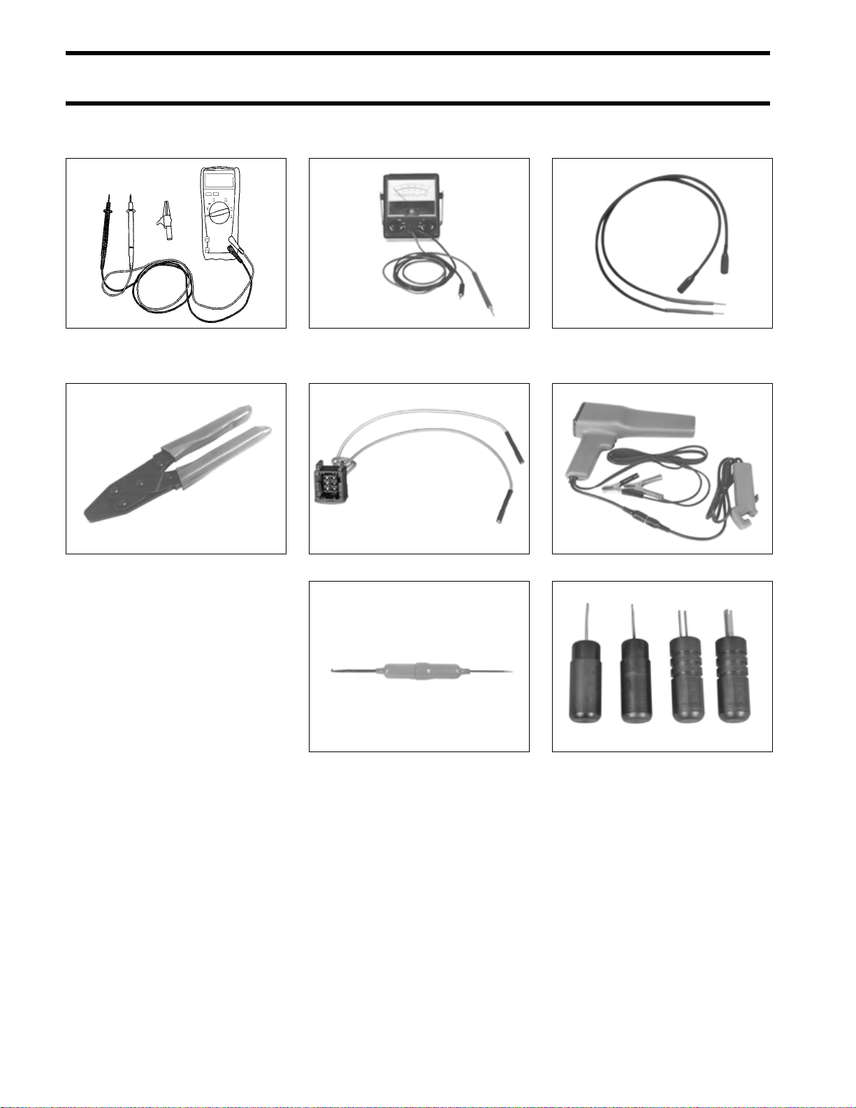
Digital multimeter
Ohms resolution 0.01
Purchase through local supplier
Crimping pliers P/N 322696 30387
DRC7265
Peak reading voltmeter
P/N 507972
Stator Test Adapter P/N 5006211 004222
49799
Test probe kit P/N 342677 45241
Tachometer/timing light P/N 507980 49789
18
Connector tool P/N 342667 42004
†
connector tools
AMP
Primary Lock Tool P/N 777077
Secondary Lock Tool P/N 777078
Release Tool P/N 351413
Lock Installer P/N 777079
002277
Page 21
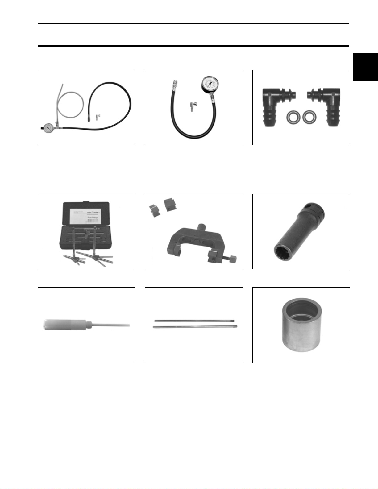
FUEL /OIL SYSTEM TOOLS
SPECIAL TOOLS
FUEL /OIL SYSTEM TOOLS
1
Fuel pressure gauge (60 PSI)
P/N 5007100
90° fitting, P/N 353322
005339
Fuel pressure gauge (15 PSI)
P/N 5006397
90° fitting, P/N 353322
POWERHEAD TOOLS
Cylinder bore gauge P/N 771310 45303
Rod cap alignment fixture
P/N 396749
004560
21596
Injector test fitting kit
P/N 5005844
Torquing socket P/N 346187 50242
002465
Piston stop tool P/N 342679
Replacement tip P/N 5006098
46543
Guide rods
P/N 383175
000828
Crankshaft bearing and sleeve
installer P/N 338649
21953C
19
Page 22

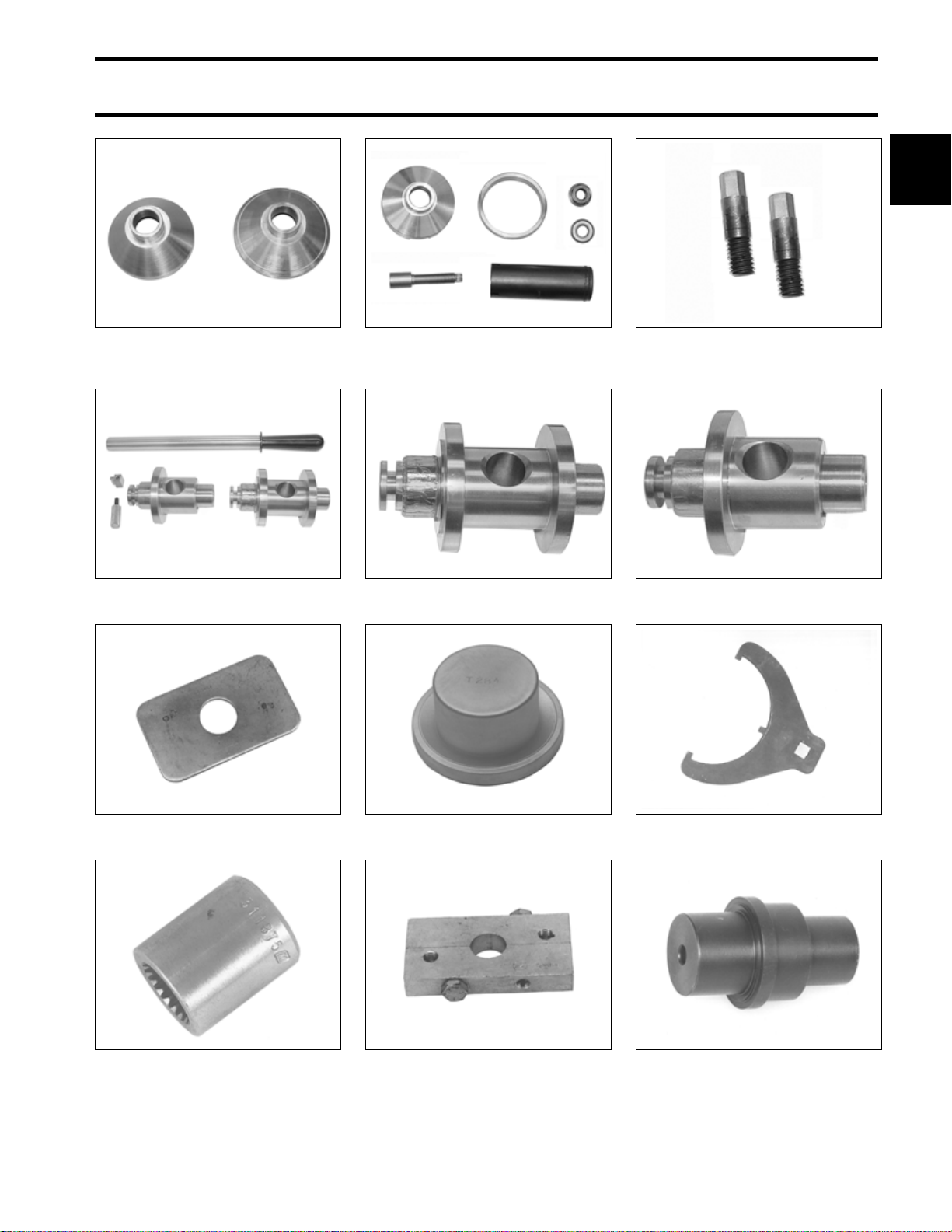
SPECIAL TOOLS
GEARCASE TOOLS
1 2
Wrist pin pressing tool
P/N 396747
23668
1. Wrist pin retaining ring driver
2. Wrist pin cone P/N 331913
GEARCASE TOOLS
P/N 396747
DR1641
Seal installation tool P/N 325453 23651
Universal Driveshaft Shimming Tool
P/N 5005925
1. Lower Driveshaft Shimming Bolt
(S2 gearcase) P/N352878
Gearcase filler
P/N 501882
1
002601
49790
Universal Pinion Bearing Remover
and installer kit P/N 5005927
Gearcase pressure tester
P/N 507977 (Stevens P/N S-34)
Gearcase vacuum tester
P/N 507982 (Stevens P/N V-34)
002805
49794
Universal shift rod height gauge
P/N 389997
Pressing fixture P/N 354059 006782
32872
20
Page 23
SPECIAL TOOLS
GEARCASE TOOLS
1
Prop shaft bearing housing
installers P/N 354058 (L2)
P/N 354057 (M2)
Gearcase Alignment Gauge Kit
P/N 5006349
006783
004315
Prop shaft bearing housing
remover/puller P/N 354060
Gauging Head, “M2” Type
Gearcases, P/N 5007749
006784
006822
Prop shaft bearing housing
alignment pins P/N 354140
Gauging Head, “L2” Type
Gearcases, P/N 5007750
006788
006823
Backing plate P/N 325867 23621
Driveshaft socket P/N 311875 23261
Bearing Installation Tool
P/N 339778
Driveshaft Puller P/N 390706 32884
32519
Spanner wrench P/N 432400 15358
Prop shaft bearing installer
P/N 432401
15355
21
Page 24
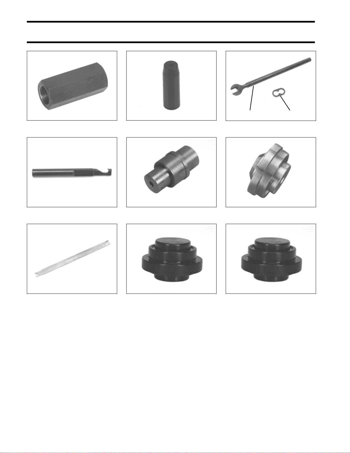
SPECIAL TOOLS
GEARCASE TOOLS
Slide hammer adapter P/N 432398 15356
Driveshaft seal protector
P/N 318674
23692
1 2
1. Pinion nut holder P/N 334455
2. Wrench retainer P/N 341438
40371
Lower Driveshaft Puller P/N 342681 47257
Pinion nut starting tool P/N 342216 40372
Prop shaft bearing installer
P/N 339750
Prop shaft housing seal installer
P/N 336311
32880
32973
Seal installation tool P/N 330268 32924
Seal installation tool P/N 354056 006824
22
Page 25
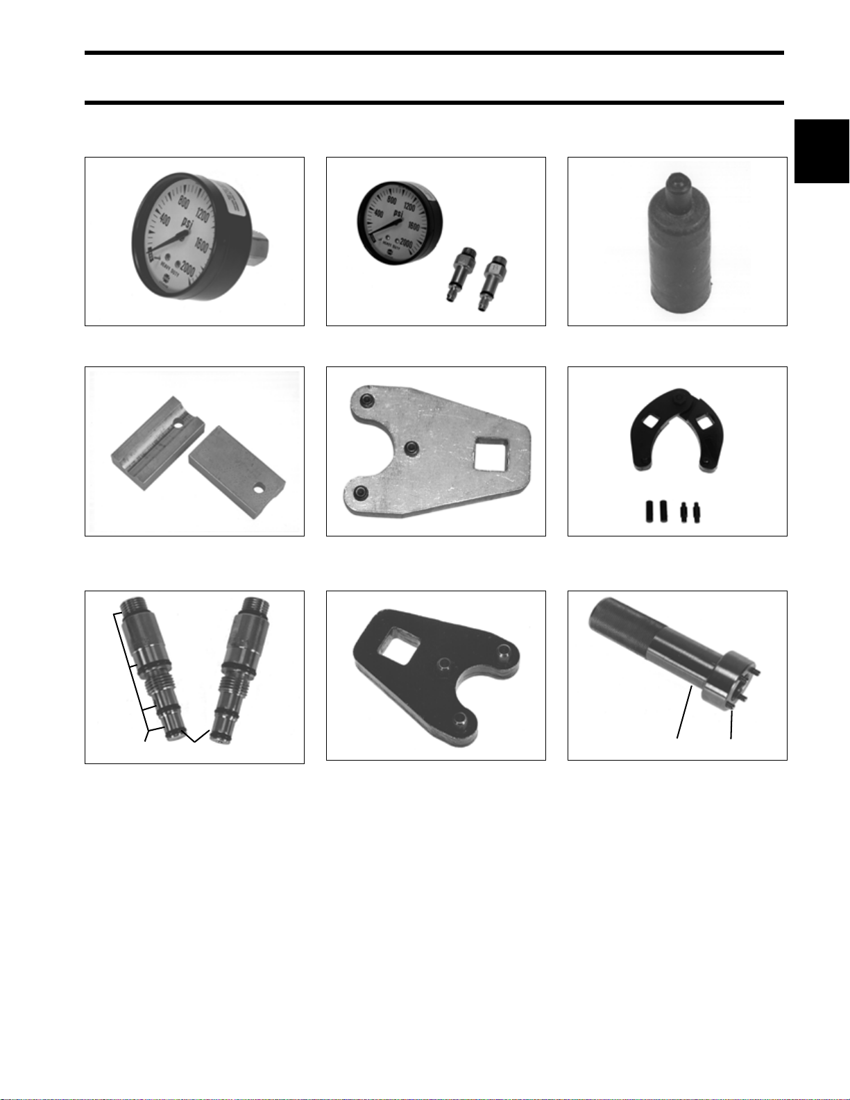
TRIM AND TILT TOOLS
SPECIAL TOOLS
TRIM AND TILT TOOLS
1
Gauge and collar assembly
P/N 983975
Hydraulic cylinder rod holder
P/N 983213
33023
23665
Trim/tilt service kit P/N 390010 33013
Tilt cylinder end cap remover
P/N 352932, for single-piston
tilt systems
005340
Tilt cylinder seal protector
P/N 326005
Spanner wrench P/N 912084 32213
23694
2 1
1. Trim/tilt service kit P/N 434524
2. Replacement o-ring kit for
adapter tips P/N 434729
27340
Tilt cylinder end cap remover
P/N 326485, for three-piston
tilt systems
33741
12
1. Trim cylinder end cap
remover/installer P/N 436710
2. Replacement tip for 436710
33742A
23
Page 26
SPECIAL TOOLS
SHOP AIDS
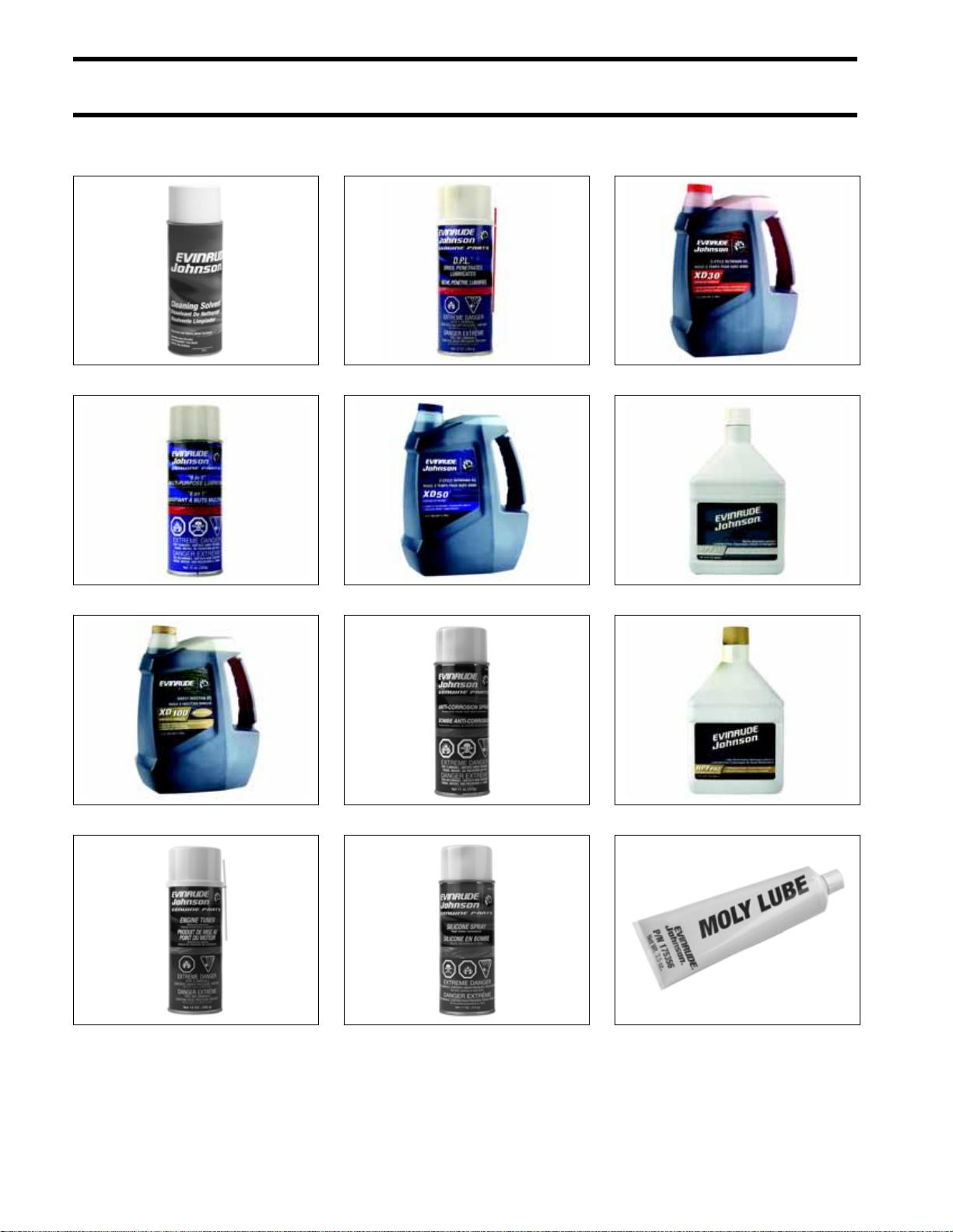
SHOP AIDS
Cleaning Solvent P/N 771087
“6 in 1” Multi-Purpose Lubricant P/N 777192
Oil - XD100™ P/N 764357
D.P.L. Spray P/N 777183
Oil - XD50™ P/N 764354
Anti-Corrosion Spray P/N 777193
Oil - XD30™ P/N 764349
HPF XR™ Gear Lube P/N 778749
HPF PRO Gearcase Lube P/N 778755
Engine Tuner P/N 777185
24
Silicone spray P/N 775630
Moly Lube P/N 175356
Page 27
SPECIAL TOOLS
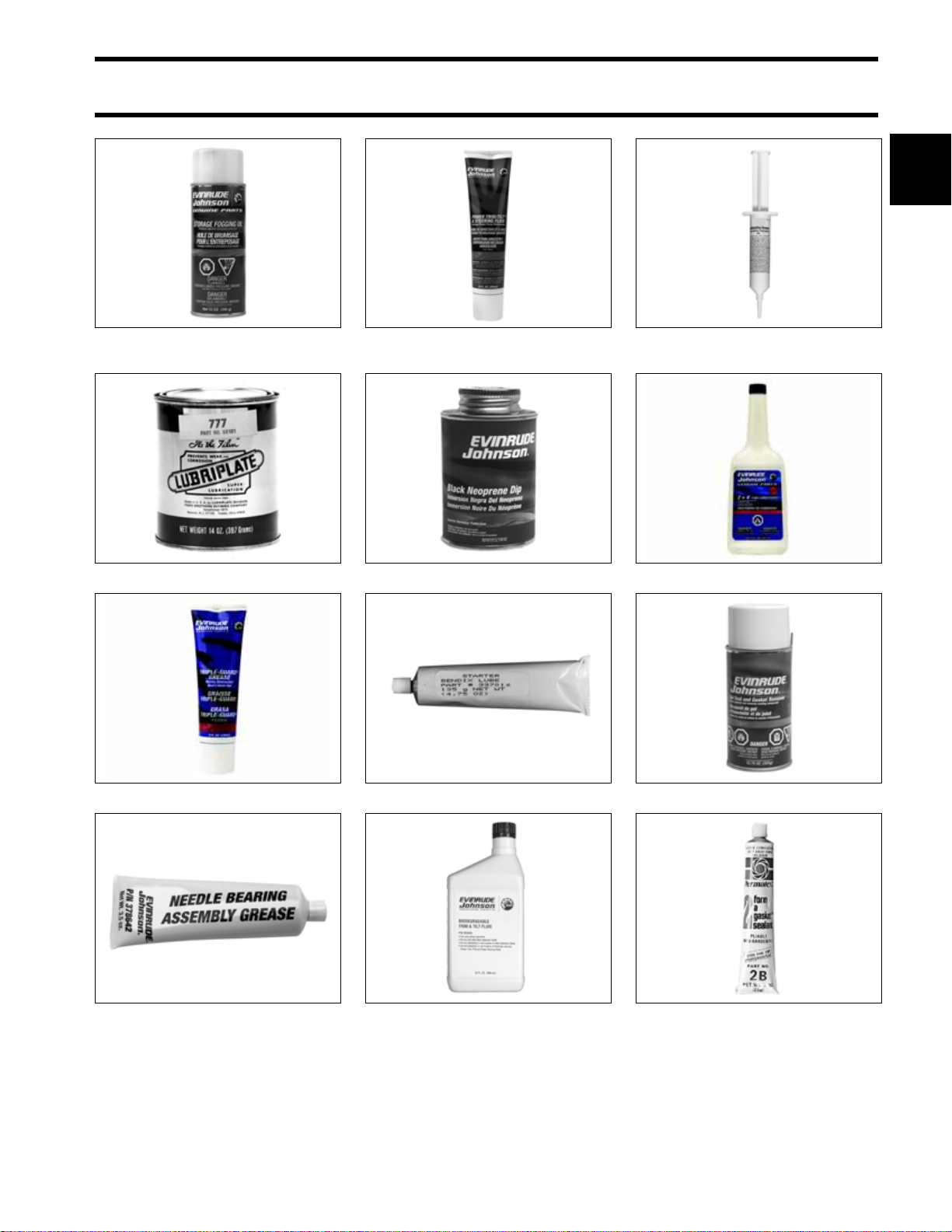
SHOP AIDS
1
Storage Fogging Oil
P/N 777186
Lubriplate† 777 P/N 317619
Power Trim/Tilt and Power Steering Fluid
P/N 775612
Black Neoprene Dip P/N 909570
Electrical Grease P/N 503243
2 + 4™ Fuel conditioner P/N 775613
Triple-Guard® Grease P/N 508298
Needle Bearing Grease, P/N 378642
Starter Bendix Lube P/N 337016
Biodegradeable TNT Fluid
P/N 763439
Gel-Seal and Gasket Remover P/N 771050
†
Permatex
No. 2, P/N 910032
25
Page 28
SPECIAL TOOLS
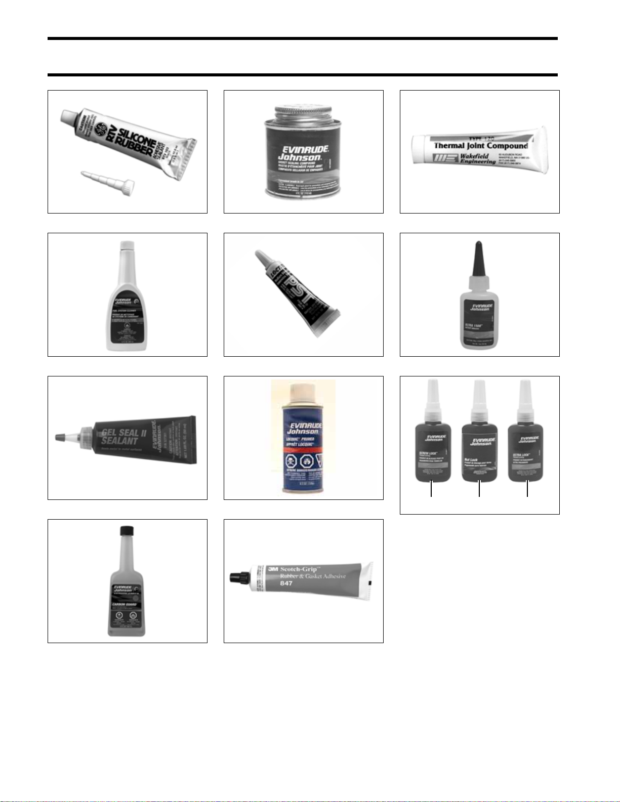
SHOP AIDS
RTV Silicone Sealant P/N 263753
Fuel System Cleaner P/N 763681
Gel·Seal II P/N 327361
Gasket Sealing Compound P/N 508235
Pipe Sealant with Teflon P/N 910048
Locquic Primer P/N 772032
Thermal Joint Compound P/N 322170
Instant Bonding Adhesive P/N 509955
1 2 3
1. Screw Lock P/N 500417
2. Nut Lock P/N 500421
3. Ultra Lock P/N 500423
†
Purple 222 equivalent
(Loctite
(Loctite Blue 242 Equivalent)
(Loctite Red 271 Equivalent)
Carbon Guard™ P/N 775629
26
Adhesive 847 P/N 776964
Page 29

INSTALLATION AND PREDELIVERY
INSTALLATION AND PREDELIVERY
TABLE OF CONTENTS
BOAT RIGGING . . . . . . . . . . . . . . . . . . . . . . . . . . . . . . . . . . . . . . . . . . . . . . . . . . . . . . . . . . . . . . . . . . . . .28
REMOTE CONTROLS . . . . . . . . . . . . . . . . . . . . . . . . . . . . . . . . . . . . . . . . . . . . . . . . . . . . . . . . . . . . . . .28
BATTERY INSTALLATION . . . . . . . . . . . . . . . . . . . . . . . . . . . . . . . . . . . . . . . . . . . . . . . . . . . . . . . . . . . .29
BATTERY SWITCHES AND MULTIPLE BATTERIES . . . . . . . . . . . . . . . . . . . . . . . . . . . . . . . . . . . . . . . . . .30
AUXILIARY BATTERY CHARGING . . . . . . . . . . . . . . . . . . . . . . . . . . . . . . . . . . . . . . . . . . . . . . . . . . . . . .32
FUEL SYSTEM REQUIREMENTS . . . . . . . . . . . . . . . . . . . . . . . . . . . . . . . . . . . . . . . . . . . . . . . . . . . . . . .35
OILING SYSTEM SET-UP . . . . . . . . . . . . . . . . . . . . . . . . . . . . . . . . . . . . . . . . . . . . . . . . . . . . . . . . . . . . .37
CABLE AND HOSE INSTALLATION . . . . . . . . . . . . . . . . . . . . . . . . . . . . . . . . . . . . . . . . . . . . . . . . . . . . .40
OUTBOARD INSTALLATION . . . . . . . . . . . . . . . . . . . . . . . . . . . . . . . . . . . . . . . . . . . . . . . . . . . . . . . . . .44
HULL PREPARATION . . . . . . . . . . . . . . . . . . . . . . . . . . . . . . . . . . . . . . . . . . . . . . . . . . . . . . . . . . . . . . .44
TRANSOM MEASURING AND DRILLING . . . . . . . . . . . . . . . . . . . . . . . . . . . . . . . . . . . . . . . . . . . . . . . . . .46
LIFTING THE OUTBOARD . . . . . . . . . . . . . . . . . . . . . . . . . . . . . . . . . . . . . . . . . . . . . . . . . . . . . . . . . . . .49
STEERING SYSTEMS . . . . . . . . . . . . . . . . . . . . . . . . . . . . . . . . . . . . . . . . . . . . . . . . . . . . . . . . . . . . . . .49
OUTBOARD MOUNTING . . . . . . . . . . . . . . . . . . . . . . . . . . . . . . . . . . . . . . . . . . . . . . . . . . . . . . . . . . . . .51
OUTBOARD RIGGING . . . . . . . . . . . . . . . . . . . . . . . . . . . . . . . . . . . . . . . . . . . . . . . . . . . . . . . . . . . . . . . .52
CABLE, HOSE, AND WIRE ROUTING . . . . . . . . . . . . . . . . . . . . . . . . . . . . . . . . . . . . . . . . . . . . . . . . . . . . 52
CONTROL CABLE INSTALLATION . . . . . . . . . . . . . . . . . . . . . . . . . . . . . . . . . . . . . . . . . . . . . . . . . . . . . .53
ELECTRICAL HARNESS CONNECTIONS . . . . . . . . . . . . . . . . . . . . . . . . . . . . . . . . . . . . . . . . . . . . . . . . . 55
WATER PRESSURE GAUGE . . . . . . . . . . . . . . . . . . . . . . . . . . . . . . . . . . . . . . . . . . . . . . . . . . . . . . . . . .55
CANBUS CONNECTIONS . . . . . . . . . . . . . . . . . . . . . . . . . . . . . . . . . . . . . . . . . . . . . . . . . . . . . . . . . . . .56
FUEL AND OIL PRIMING . . . . . . . . . . . . . . . . . . . . . . . . . . . . . . . . . . . . . . . . . . . . . . . . . . . . . . . . . . . . .58
FUEL REQUIREMENTS . . . . . . . . . . . . . . . . . . . . . . . . . . . . . . . . . . . . . . . . . . . . . . . . . . . . . . . . . . . . . .58
FUEL SYSTEM PRIMING . . . . . . . . . . . . . . . . . . . . . . . . . . . . . . . . . . . . . . . . . . . . . . . . . . . . . . . . . . . . .59
OIL REQUIREMENTS . . . . . . . . . . . . . . . . . . . . . . . . . . . . . . . . . . . . . . . . . . . . . . . . . . . . . . . . . . . . . . .59
OIL INJECTION RATE . . . . . . . . . . . . . . . . . . . . . . . . . . . . . . . . . . . . . . . . . . . . . . . . . . . . . . . . . . . . . . .60
BREAK-IN OILING . . . . . . . . . . . . . . . . . . . . . . . . . . . . . . . . . . . . . . . . . . . . . . . . . . . . . . . . . . . . . . . . .61
OIL SUPPLY PRIMING . . . . . . . . . . . . . . . . . . . . . . . . . . . . . . . . . . . . . . . . . . . . . . . . . . . . . . . . . . . . . .61
BEFORE START-UP . . . . . . . . . . . . . . . . . . . . . . . . . . . . . . . . . . . . . . . . . . . . . . . . . . . . . . . . . . . . . . . . .63
RUNNING CHECKS . . . . . . . . . . . . . . . . . . . . . . . . . . . . . . . . . . . . . . . . . . . . . . . . . . . . . . . . . . . . . . . . . .64
ENGINE MONITORING SYSTEM . . . . . . . . . . . . . . . . . . . . . . . . . . . . . . . . . . . . . . . . . . . . . . . . . . . . . . . .64
FUEL SYSTEM . . . . . . . . . . . . . . . . . . . . . . . . . . . . . . . . . . . . . . . . . . . . . . . . . . . . . . . . . . . . . . . . . . . .64
EMERGENCY STOP / KEY SWITCH . . . . . . . . . . . . . . . . . . . . . . . . . . . . . . . . . . . . . . . . . . . . . . . . . . . . .64
START-IN-GEAR PREVENTION . . . . . . . . . . . . . . . . . . . . . . . . . . . . . . . . . . . . . . . . . . . . . . . . . . . . . . . . 64
TACHOMETER PULSE SETTING . . . . . . . . . . . . . . . . . . . . . . . . . . . . . . . . . . . . . . . . . . . . . . . . . . . . . . .65
WATER PUMP OVERBOARD INDICATOR . . . . . . . . . . . . . . . . . . . . . . . . . . . . . . . . . . . . . . . . . . . . . . . . .65
BREAK-IN . . . . . . . . . . . . . . . . . . . . . . . . . . . . . . . . . . . . . . . . . . . . . . . . . . . . . . . . . . . . . . . . . . . . . . . 65
PROPELLERS . . . . . . . . . . . . . . . . . . . . . . . . . . . . . . . . . . . . . . . . . . . . . . . . . . . . . . . . . . . . . . . . . . . . . .66
PROPELLER SELECTION . . . . . . . . . . . . . . . . . . . . . . . . . . . . . . . . . . . . . . . . . . . . . . . . . . . . . . . . . . . .66
PROPELLER HARDWARE INSTALLATION . . . . . . . . . . . . . . . . . . . . . . . . . . . . . . . . . . . . . . . . . . . . . . . .67
FINAL ADJUSTMENTS . . . . . . . . . . . . . . . . . . . . . . . . . . . . . . . . . . . . . . . . . . . . . . . . . . . . . . . . . . . . . . .68
TILT LIMIT SWITCH ADJUSTMENT . . . . . . . . . . . . . . . . . . . . . . . . . . . . . . . . . . . . . . . . . . . . . . . . . . . . . .68
TRIM SENDING UNIT ADJUSTMENT . . . . . . . . . . . . . . . . . . . . . . . . . . . . . . . . . . . . . . . . . . . . . . . . . . . .69
TRIM TAB ADJUSTMENT . . . . . . . . . . . . . . . . . . . . . . . . . . . . . . . . . . . . . . . . . . . . . . . . . . . . . . . . . . . .70
DUAL-OUTBOARD ALIGNMENT . . . . . . . . . . . . . . . . . . . . . . . . . . . . . . . . . . . . . . . . . . . . . . . . . . . . . . .71
NOTES . . . . . . . . . . . . . . . . . . . . . . . . . . . . . . . . . . . . . . . . . . . . . . . . . . . . . . . . . . . . . . . . . . . . . . . . . . . .72
2
27
Page 30
INSTALLATION AND PREDELIVERY
BOAT RIGGING
BOAT RIGGING
Remote Controls
Control Selection
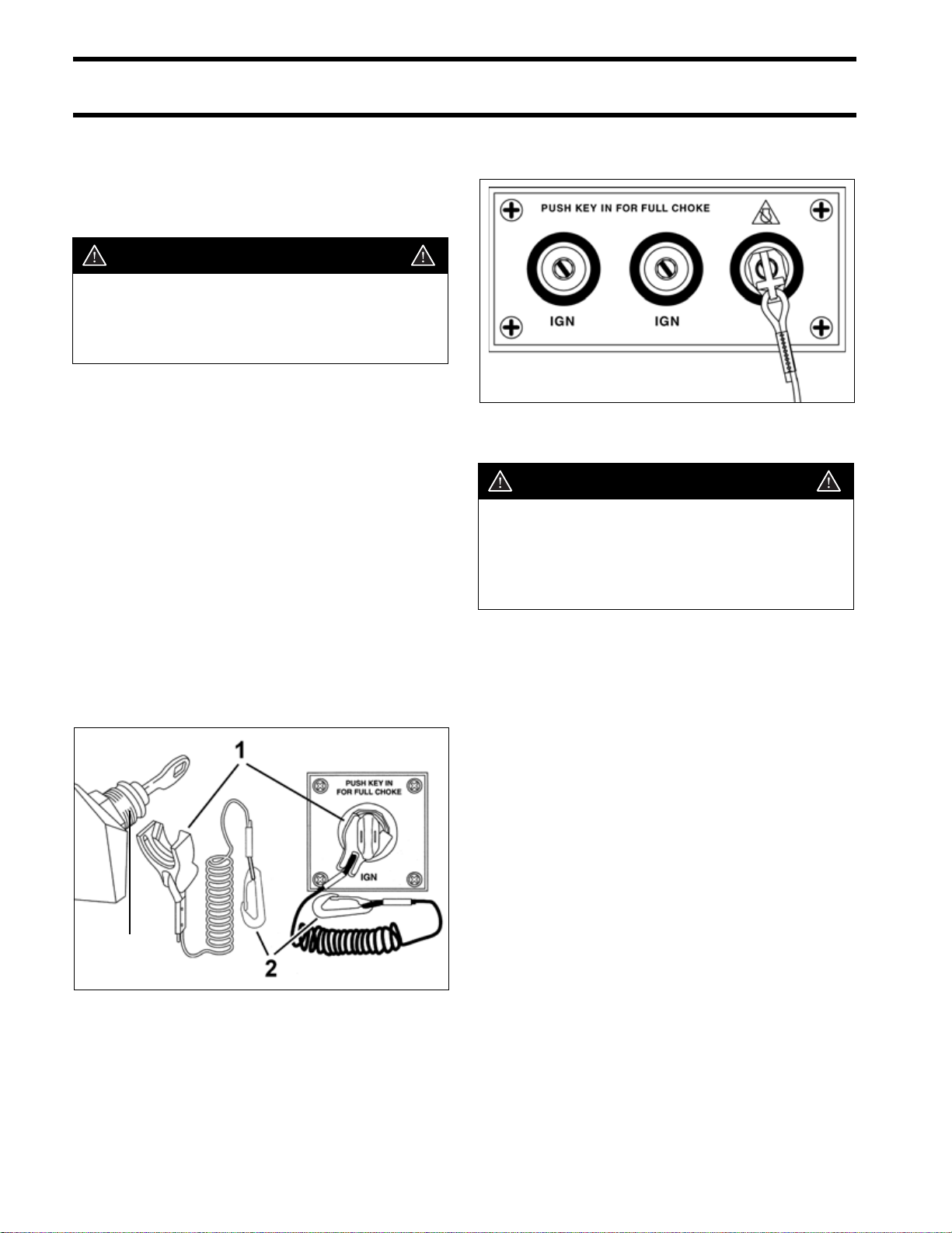
WARNING
The remote control used must have startin-gear prevention. This feature can prevent injuries resulting from unexpected
boat movement when the outboard starts.
Remote control styles and applications are
described in the Evinrude/Johnson Genuine Parts
and Accessories Catalog. Plan the installation of
all remote controls carefully. Read the outboard's
Operator's Guide and the remote control's installation instructions prior to installation.
The remote control and wiring harness used must
have the following features:
• Start-in-gear prevention
• Emergency stop / key switch
• Shift stroke must measure 1.125 to 1.330 in.
(28.6 to 33.8 mm) between NEUTRAL and
FORWARD
• Throttle stroke must PUSH for open
• All wiring must be compatible with Modular Wir-
ing System (MWS) components
• Dual-outboard controls require separate key
switches with a single emergency stop switch.
Dual-outboard key switches with emergency stop
switch
DRC40118
WARNING
Always install and recommend use of an
emergency stop/key switch. Doing so will
reduce the risk of personal injury or death
should the operator fall away from the controls or out of the boat.
Engine Monitoring System
IMPORTANT: Outboards with remote controls
must be equipped with an I-Command system, a
SystemCheck gauge, or an equivalent engine
monitor. Operating the outboard without an
engine monitor will void the warranty for failures
related to monitored functions.
3
1. Emergency stop clip
2. Safety lanyard
3. Key switch with emergency stop feature
28
Refer to ENGINE MONITORING SYSTEM on
p. 101.
002817
Page 31

INSTALLATION AND PREDELIVERY
BOAT RIGGING
Control Installation
Plan the installation of remote controls carefully,
following all instructions provided with the remote
control.
Make sure the following items are checked:
• Correct length, type and quality of control
cables and wiring harnesses
• Proper routing of cables and harnesses
• Slack in front of the outboard for remote control
cables
• Positioning and securing of cables and har-
nesses along their lengths to prevent movement
or damage.
Typical transom-mounted outboard installations
require a 12 in. (30 cm) cable loop at the front of
the outboard when the cables are routed from the
side of the splash well.
Battery Installation
Each outboard requires its own starting battery.
Select a battery that meets or exceeds the minimum requirements.
Minimum 12 Volt Battery Recommendations
Outboard Model Battery Rating
115–300 HP 675 CCA (845 MCA), or
750 CCA (940 MCA)
below 32°F (0°C)
107 amp-hr in extreme
applications
Location and Preparation
Proper installation will prevent battery movement
while underway.
• Secure all batteries in protected locations.
• Place battery as close to the outboard as possi-
ble.
• Battery location must provide access for peri-
odic maintenance.
• Use battery mounting trays or battery boxes on
all battery installations.
• Connections and terminals must be covered
with an insulator.
• Battery connections must be clean and free
from corrosion.
• Read and understand the safety information
supplied with the battery before installation.
2
123
1. Surface side-mount remote control
2. Cable support
3. 12 in. (30 cm) cable loop at front of outboard
DR4277
IMPORTANT: Cables of the proper length,
style, and quality that are correctly installed and
adjusted will eliminate most control-related operational problems.
WARNING
Keep the battery connections clean, tight,
and insulated to prevent their shorting or
arcing and causing an explosion. If the battery mounting system does not cover the
connections, install protective covers.
Check often to see that connections stay
clean and tight.
29
Page 32

INSTALLATION AND PREDELIVERY
BOAT RIGGING
Connections
IMPORTANT: Connect the battery positive (+)
cable to the battery positive (+) post FIRST. Connect the battery negative (–) cable to the battery
negative (–) post LAST.
Install a starwasher on the threaded battery post.
Stack cables from the outboard, then cables from
accessories. Finish this connection with a hex nut.
3
2
1
Marine Style Battery Post
1. Starwasher
2. Hex nut
3. Terminal Insulator
DR5103
IMPORTANT: Do not use wing nuts to fasten
ANY battery cables. Wing nuts can loosen and
cause electrical system damage not covered
under warranty.
Tighten all connections securely. Apply Triple-
Guard grease to prevent corrosion.
Battery Cable Requirements
Evinrude outboards are shipped with stranded
copper battery cables for typical installations in
which the starting battery is positioned close to
the transom.
Specialized outboard installations with extended
length battery cables require an increased wire
size. Refer to the following table.
IMPORTANT: Inadequate battery cables can
affect the performance of an outboard’s high
amperage start circuit and the cranking speed of
the outboard. DO NOT use aluminum wire cables.
Use ONLY AWG stranded copper wire cables.
40–250 HP
1 to 10 Ft.
(.3 to 3 m)
11 to 15 Ft.
(3.4 to 4.6 m)
16 to 20 Ft.
(4.9 to 6.1 m)
4 Gauge
2 Gauge
1 Gauge
Battery Switches and Multiple Batteries
A multiple battery setup, including marine battery
selector switches, can provide flexibility in single
and dual outboard installations.
30
Refer to Battery and Switch Wiring Diagrams
on p. 33 for various battery connection options.
The battery selection function can be used for
emergency starting if a primary battery becomes
discharged.
The OFF position of the battery selector switch
can be used to minimize battery discharge during
periods of non-use.
Page 33

INSTALLATION AND PREDELIVERY
BOAT RIGGING
Typical battery functions
IMPORTANT: Never connect an external bat-
tery isolator to the stator of an Evinrude E-TEC.
Primary
• Used as starting battery under normal operating
conditions.
• Red (+) cable connected to battery selector
switch.
• Primary battery is charged by connection to
main red (+) outboard battery cable.
Dual outboard installations can utilize the opposing outboard's primary battery as a secondary battery for emergency starting only.
Secondary
• Used as back-up starting battery under abnor-
mal operating conditions.
• Red (+) cable connected to battery selector
switch.
• Secondary battery is charged independently
from primary battery.
Accessory
• Not used as starting battery.
• Isolated from outboard start function.
• No red (+) cable connected to battery selector
switch.
Secondary and accessory batteries are often
charged by an isolated battery charging circuit.
Refer to Auxiliary Battery Charging on p. 32.
Battery Switch Requirements
Battery switches must meet the following requirements.
• The switch must be approved for marine use.
• The switch should be a “make before break”
design to protect the charging system from a
no-load condition.
• Switch amperage rating should be adequate for
the outboard it will be used on.
• Use one battery switch for each outboard
installed.
• Use the appropriate sized wire and terminals for
all connections.
• Use AWG stranded copper wire.
Battery Switch Location
• Always locate battery switch as close to the bat-
teries as possible.
• Locate switch so that it cannot be accidently
bumped or switched.
• Refer to the battery switch manufacturer’s
installation instructions for specific information
related to the installation of switch.
• Fasten all battery switches to solid surfaces.
• Route wiring as directly as possible.
• Support the battery switch as needed to prevent
abrasion.
• Use appropriate wiring and connectors.
• Seal all connections and terminals with liquid
neoprene or electrical sealer to prevent corrosion.
IMPORTANT: Insulate all battery positive (+)
terminals to prevent shorting.
2
31
Page 34

INSTALLATION AND PREDELIVERY
BOAT RIGGING
Battery Switch Operation
• Select the primary battery for normal operation.
• Secondary batteries should only be selected for
emergency starting.
• ALL or BOTH switch position is for emergency
starting only.
Provide operator with the documentation supplied by the battery switch manufacturer. Make
sure that the operator is informed of proper
battery switch operation.
IMPORTANT: The negative (–) terminals of a
multiple 12-volt battery installation must be connected together.
3
Auxiliary Battery Charging
Evinrude E-TEC V4–V6 outboards are equipped
with isolated battery charging capability. The isolated charge connection must only be used to
charge a single 12-volt battery or two 12-volt batteries wired in parallel.
IMPORTANT: Never connect an external bat-
tery isolator to the stator of an Evinrude E-TEC
outboard.
Accessory Charge Lead Kit, P/N 5006253, is
routed from a connector on the outboard’s electrical panel to the accessory battery.
1
1 2
1. Starting battery (primary)
2. Accessory battery (secondary)
3. Cable connecting negative (–) battery terminals
DRC7284
1. Accessory battery charge connector 003912
IMPORTANT: The accessory charging kit must
never be connected to any battery of a 24-volt
electrical system.
32
Page 35

Battery and Switch Wiring Diagrams
O
t
O
INSTALLATION AND PREDELIVERY
BOAT RIGGING
ne outboard: Battery disconnec
S
ON
OFF
+
#1
PRIMARY
000135rev1
ne outboard: One primary starting
battery; one secondary battery
S
BOTH
2
OFF
+
SECONDARY
+
#1
PRIMARY
1
2
#2
Two outboards: Two starting batteries for each outboard
#1
S
BOTH
2
1
OFF
+
#1
SECONDARY
Positive (+) Battery cables
Negative (–) Battery cables
Accessory charge wires, P/N 5006253
50 amp Fuse
+
SECONDARY
+
#1
PRIMARY
1
#2
1
BOTH
2
OFF
#2
S
2
+
#2
PRIMARY
000134N
33
Page 36

INSTALLATION AND PREDELIVERY
BOAT RIGGING
Two outboards: One primary starting battery for each outboard; one isolated accessory battery
+
#1
PRIMARY
1
BOTH
OFF
#1
1
S
BOTH
2
OFF
S
2
+
ACCESSORY
#2
+
#2
PRIMARY
Two outboards: One primary starting battery for each outboard; two isolated accessory batteries
+
#1
PRIMARY
#1
S
BOTH
2
1
OFF
+
#1
ACCESSORY
Positive (+) Battery cables
Negative (–) Battery cables
Accessory charge wire, P/N 5006253
50 AMP Fuse
+
#2
ACCESSORY
#2
S
BOTH
2
1
OFF
+
#2
PRIMARY
000086N
34
Page 37

INSTALLATION AND PREDELIVERY
BOAT RIGGING
Fuel System Requirements
Overview
Boat fuel systems must meet minimum specifications to insure the proper delivery of fuel to the
outboard.
The guidelines established by the ABYC and U.S.
Coast Guard should always be followed.
• Permanent fuel tanks must be properly vented
outside of the hull.
• Remote fuel tank gas fills must be grounded.
• Permanent fuel tank pickups should have the
correct anti-siphon valve installed to prevent
fuel flow if a leak occurs in the fuel distribution
system. Refer to ABYC Standard H-24.
Fuel Hose
All fuel hoses must be designated as fuel hose
and approved for marine use.
• Use only fuel lines (or copper tubing) that meet
the outboard minimum I.D. requirement.
• “USCG Type A1” fuel hose must be used
between permanent fuel tanks and motor well
fittings on inaccessible routings.
• Use “USCG Type B1” for fuel hose routings in
motor well areas.
• Permanently installed fuel hoses should be as
short and horizontal as possible.
• Use corrosion-resistant metal clamps on per-
manently installed fuel hoses.
• Multi-outboard applications require separate
fuel tank pickups and hoses. (A fuel selector
switch may be used for “kicker” motors as long
as it has enough flow capacity for the larger outboard.)
Fuel System Primer
Outboards require a priming system capable of
refilling the fuel system after periods of non-use.
Primer bulbs that meet the outboard's minimum
inside diameter fuel line requirements are used on
most outboards.
Install the primer bulb in the fuel supply hose as
follows:
• The primer bulb should be installed in an acces-
sible location.
• The arrow on the primer bulb must point in the
direction of fuel flow.
• The fuel primer bulb must be positioned in the
fuel supply hose so the primer bulb can be held
with the arrow pointing “up” during priming.
1
1. Arrow indicates direction of fuel flow 000124
An alternative to a primer bulb is a U.S. Coast
Guard approved marine primer pump. Electric
primer pumps offer the convenience of outboard
priming from a dash-mounted momentary switch.
2
35
Page 38

INSTALLATION AND PREDELIVERY
BOAT RIGGING
Fuel Filters
Boat-mounted fuel filters and water-separating
fuel filter assemblies must meet the required fuel
flow and filter specification. The filter must be
mounted to a rigid surface above the “full” level of
the fuel tank and accessible for servicing.
Fuel Filter Assembly, P/N 174176, meets all
requirements for a water-separating fuel filter.
1 2 3
Typical Fuel Supply Configuration
1. Primer bulb
2. Water separating fuel filter
3. Anti-siphon valve, in fuel pick-up of tank
DRC6797
IMPORTANT: Avoid using “in-line” fuel filters.
The filter area and flow characteristics may not be
adequate for high horsepower outboards.
Portable Fuel Tanks
Do not use portable fuel tanks for outboards larger
than 115 HP. Inadequate fuel flow to high horse-
0070
power outboards can result in serious powerhead
damage.
Outboard Fuel System Recommendations
Component 25 HP – 130 HP Models 135 HP – 250 HP Models
Fuel tank pickup tube 5/16 in. (7.9 mm) min. I.D. 3/8 in. (9.5 mm) min. I.D.
Fuel fittings 1/4 in. (6.4 mm) min. I.D. 9/32 in. (7.1 mm) min. I.D.
Fuel supply hoses 5/16 in. (7.9 mm) min. I.D. 3/8 in. (9.5 mm) min. I.D.
ALL MODELS
Fuel tank pickup screen 100 mesh, 304 grade stainless steel wire, 0.0045 in. wire diameter,
1 in. (25 mm) long
Antisiphon valve 2.5 in. (63.5 mm) Hg maximum pressure drop at 20 gph (76 l/hr)
flow
Remote fuel filter 0.4 in. Hg maximum pressure drop at 20 gph (76 l/hr) flow,
150 in.
Maximum fuel pump lift height Fuel pump should not be located more than 30 in. (76.2 cm) above
bottom of fuel tank
2
(1290 cm2) of filter area
36
Page 39

INSTALLATION AND PREDELIVERY
BOAT RIGGING
Oiling System Set-Up
Location
IMPORTANT:
of the oil tank carefully. The oil tank is vented to
the atmosphere. To avoid serious powerhead
damage, be sure the oil tank is installed in a location that does not allow constant exposure to sunlight, rain, bilge water or spray.
Select a mounting location that provides:
• A solid place to mount the tank;
• A dry location that prevents exposure to rain or
spraying water;
• Access for adding oil;
• Access to oil-primer bulb; and
• Interference-free hose and wire routing to out-
board.
If necessary, the oil tank can be mounted further
from the outboard than the supplied hoses and
harness allow. The maximum length of oil supply
hose that can be fitted to the oil tank is 25 ft.
(7.6 m).
Consider the installation location
• Replacement hose must be designated for fuel
or oil use and approved for marine use.
• Extend wiring harness with 16 gauge AWG
wire.
• Protect connections with heat shrink tube.
• Maintain wire color and polarity when extending
harness.
An appropriately sized battery box may be used to
conceal and protect the oil tank, if desired.
IMPORTANT: Be sure box includes drain holes
so it does not fill with water and contaminate oil.
2
IMPORTANT: Do not add hose to an existing oil
supply hose.
If the oil tank requires a longer oil supply hose:
• Oil supply hose between the primer bulb and
outboard must be replaced with one continuous
length of 1/4 in. (6.4 mm) hose.
• Maximum length of hose is 25 ft. (7.6 m).
000074
Mounting
Place tank in selected position. Mark one line
under groove in tank bottom and lines at each end
of tank.
1
2
1. Center line of oil tank
2. Ends of tank
Make sure hole locations provide enough clearance for fastening screws. Screws should not contact or penetrate hull.
2
44737
37
Page 40

INSTALLATION AND PREDELIVERY
BOAT RIGGING
Place floor bracket on center line between end
lines. Use the inner bracket holes as guides to drill
two 5/32 in. (4 mm) pilot holes.
COB5381
3 GALLON (11.4 L) TANK
Place rods into floor bracket and secure floor
bracket with lag bolts.
1
1
1.8 GALLON TANK
Place rods into floor bracket and secure floor
bracket with lag bolts.
1
2
1. Rods
2. Lag bolts
Place oil tank onto floor bracket. If cover is not
pre-assembled, route oil supply hose and harness
through the cover and position cover on the oil
tank. Attach spring-loaded rods to cover.
1
2
22149A
2
1. Rods
2. Lag bolts
2
22241B
Place oil tank onto floor bracket. Assemble crossbar onto hook rods, install flat washers and locknuts. Tighten locknuts to securely hold tank.
1
48704
1. Crossbar DRC7418
38
Page 41

Oil Tank Profiles
INSTALLATION AND PREDELIVERY
BOAT RIGGING
1.8 Gallon Tank
P/N 176995
Remote Oil Fill Kit (Optional)
The remote oil fill kit (P/N 176461) provides a
deck-mounted fill tube, cap, a tank-mounted tube,
and nut that replace the original oil tank cap
assembly.
3 Gallon Tank
P/N 176996
2
Installation Recommendations
• Select a location on the deck of the boat that is
above the oil tank fill cap.
• Select a deck location which allows the required
length of 1½ in. I.D. fill hose to route as directly
and as vertically as possible.
• Avoid inappropriate hose routings that could
distort the fill tube or tank tube.
• Refer to installation instructions provided with
remote oil fill kit.
A slanted area of the deck will allow water to
drain away from the fill and is best suited for
the installation.
DRC8123
Additional Items Required
• 1½ in. I.D. fill hose cut to required length. Fill
hose (P/N 123956) is available in 25 ft. (7.6 m)
lengths.
• Two corrosion resistant 2 in. (50 mm) hose
clamps.
39
Page 42

INSTALLATION AND PREDELIVERY
BOAT RIGGING
Cable and Hose Installation
Before installation, identify all required wiring,
cables, and hoses:
• Throttle and shift cables
• Instrument harnesses
• Battery cables and switches
• Oil tank sender harness
• Fuel supply hose
• Primer bulb or primer pump
• Oil supply hose
Determine whether any additional wiring or hoses
will be needed for accessory gauges or batteries:
• Speedometer pick-up hose
• Mechanical water pressure gauge hose
• Accessory battery charging kit
• CANbus adapter harnesses
• CANbus water pressure sensor kit
• CANbus oil level sensor kit
12345
Cable and Wire Harness Routing
WARNING
Improper installation and routing of outboard controls could wear, bind, and damage components, causing loss of control.
Remote control cables, wiring, and hoses must
follow a similar path into the lower motor covers.
Select the best routing for the specific application.
All cables, wiring, and hoses must be long enough
to provide adequate slack. Check clearances at all
possible combinations of trim angles and steering
positions.
6 7 8 9
Typical outboard installation
1. Oil tank
2. Anti-siphon valve
3. Water separating fuel filter
4. Starting battery
5. Accessory battery
6. Flexweave protective sleeve
7. Access cover
8. Primer bulb
9. Battery switch
Typical Small Splash Well DRC7799
DRC6487
Typical Large Splash Well DRC7797
40
Page 43

INSTALLATION AND PREDELIVERY
BOAT RIGGING
Fuel Hose
The fuel hose may be routed outside of the protective sleeve or conduit. Electric primers or manual primers may not require this consideration.
Typical Engine Bracket DRC7798A
Protective Sleeve/Conduit
Make sure all cables, wiring, and hoses have
been identified and fitted to the appropriate
lengths. Refer to OUTBOARD RIGGING on p. 52.
Next, bundle the components that route to the outboard with appropriate shielding, such as an
expandable “flexweave” sleeve or a flexible conduit.
Route fuel hoses with enough slack to allow the
primer bulb arrow to point “up” during use.
Install the primer bulb with the arrow pointing in
the direction of fuel flow to the outboard.
Connect the fuel supply hose from the fuel tank to
the fuel supply line at the outboard.
IMPORTANT: Do not permanently fasten this
connection until the boat's fuel system has been
primed.
Oil Supply Hose
Evinrude E-TEC V4–V6 outboards use a single oil
supply hose connected to the outboard and to the
boat-mounted oil tank.
• Route the hose from the oil tank to the ¼ in. (6.4
mm) fitting of the oil supply line at the lower
motor cover.
• Install the hose on the fitting using the proper
†
size Oetiker
clamp.
2
Flexible conduit installation 005138
Battery Cables
Evinrude outboards are equipped with premium
quality battery cables that should be long enough
for most installations.
When routing battery cables, be sure to:
• Route cables through the protective sleeve.
• Use the most direct path to route the battery
cables to the battery or battery switch.
1. Fuel supply hose and fuel fitting - 3/8 in. (9 mm)
2. Oil supply hose and fitting - 1/4 in. (6 mm)
21
003963
41
Page 44

INSTALLATION AND PREDELIVERY
BOAT RIGGING
†
Oetiker
Use Oetiker† clamps for making hose connections. These clamps provide corrosion resistance,
minimize the potential for abrasion of rigging components, and provide solid, permanent connections.
The selection and installation of an Oetiker clamp
is essential in the proper sealing of hose connections. The clamp identification numbers appear in
millimeters on the side of the clamp, near the top
of the ear. Refer to Oetiker Stainless Steel Step-
less Clamps chart for actual dimensions.
Clamp Servicing
1
WARNING
1. Clamp identification numbers 000093
DO NOT re-use Oetiker clamps. Fuel leakage could contribute to a fire or explosion.
The nominal size of the clamp should be chosen
so that, when it is assembled on the connecting
part, the outside diameter of the hose lies approximately in the middle of the clamping range of the
clamp.
Oetiker Stainless Steel Stepless Clamps
CLAMP NO. NOMINAL O.D. INCHES MILLIMETERS
Replacement Clamp I.D. Inches MM Open Closed Open Closed
346930 95 3/8 9.5 0.374 0.307 9.5 7.8
348838 105 13/32 10.5 0.413 0.346 10.5 8.8
349516 113 7/16 11.3 0.445 0.378 11.3 9.6
347107 133 1/2 13.3 0.524 0.425 13.3 10.8
347108 138 17/32 13.8 0.543 0.449 13.8 11.3
346931 140 34/64 14 0.551 0.453 14 11.5
346785 145 9/16 14.5 0.571 0.472 14.5 12
346786 157 5/8 15.7 0.618 0.52 15.7 13.2
348839 170 11/16 17 0.669 0.571 17 14.5
346150 185 23/32 18.5 0.728 0.602 18.5 15.3
346151 210 13/16 21 0.827 0.701 21 17.8
346152 256 1 25.6 1.008 0.882 25.6 22.4
346153 301 1 3/16 30.1 1.185 1.063 30.1 26.9
349759 316 1 1/4 31.6 1.244 1.122 31.6 28.4
349729 410 1 5/8 41 1.614 1.492 41 37.9
42
Page 45

INSTALLATION AND PREDELIVERY
BOAT RIGGING
Clamp Installation
A constant stress should be applied to close the
ear clamps. This method ensures a positive stress
on the hose and does not result in excessive compression or expansion of the band material.
IMPORTANT: Use only Oetiker recommended
tools to close Oetiker stepless clamps.
Oetiker pincers are available in the
Evinrude/Johnson Genuine Parts and Accessories Catalog (P/N 787145).
Clamp Removal
Method 1: Position Oetiker pincers across clamp
ear and cut clamp.
2
000108
Method 2: Lift end of stepless clamp with screwdriver.
DP0886
• Position correct size clamp over hose.
• Install hose on fitting.
• Close clamp ear fully with Oetiker pincers (pli-
ers).
12
1. Open clamp
2. Closed clamp
000092
000090
Method 3: Use Oetiker pincers (pliers) to grip
clamp. Pull clamp off of connection and discard.
000091
43
Page 46

INSTALLATION AND PREDELIVERY
OUTBOARD INSTALLATION
Control Cable Identification
IMPORTANT: Control cable function must be
identified before rigging outboard.
Identify each control cable:
• Put the control handle into NEUTRAL position.
The throttle cable casing guide will retract completely and the shift cable casing guide will go to
the midpoint of its travel.
1
2
1. Shift cable casing guide extended to midpoint
2. Throttle cable casing guide retracted
Extend the control cables and lubricate them with
Triple-Guard grease.
DP0811
OUTBOARD
INSTALLATION
Hull Preparation
Maximum Capacity
WARNING
Do not overpower the boat by installing an
outboard that exceeds the horsepower
indicated on the boat’s capacity plate.
Overpowering could result in loss of control.
Before installing outboard:
• Refer to the boat manufacturer's certification
label for maximum horsepower rating.
• Refer to ABYC Standards to determine the
maximum horsepower capacity for boats without certification labeling.
44
30501
1029A
Mounting Surface
Inspect transom surface before drilling mounting
holes.
• The transom should meet ABYC Standards.
• The transom must be flat.
• The transom angle should be approximately 14
degrees.
• Check transom strength and height.
The stern brackets must contact the flat surface of
the transom. Modify trim that prevents the stern
brackets from resting against the transom surface.
Do not modify stern brackets.
Page 47

WARNING
DO NOT install an outboard on a curved or
irregular surface. Doing so can wear, bind,
and damage components, causing loss of
control.
Transom Clearances
Make sure the transom and splash well area provide adequate clearances:
• The top edge of the transom should be wide
enough to allow full steering travel. The ABYC
standard for most single outboard installations
is 33 in. (84 cm).
• Check cable and hose routing clearances.
• Make sure there is clearance for mounting bolts
and washers. Check the inside area of the transom for obstructions before drilling holes.
INSTALLATION AND PREDELIVERY
OUTBOARD INSTALLATION
Transom Brackets and Jack Plates
When mounting an outboard on boats equipped
with transom brackets or jack plates, refer to the
manufacturer's recommendations.
• Confirm maximum weight and horsepower
capacities.
• Jack plate assemblies must provide a one-piece
mounting surface to support the outboard.
DR5704
2
Water Flow
Inspect the hull area directly in front of the mounting location.
• Boat-mounted equipment should not create tur-
bulence in the water flow directly in front of the
outboard's gearcase. Turbulence or disruptions
in the water flow directly in front of the gearcase
will affect engine cooling and propeller performance.
• Avoid locating outboard centerlines within 3 in.
(76 mm) of bottom strakes on dual-outboard
installations.
Mounting Hardware
WARNING
Use all mounting hardware supplied with
the outboard to help ensure a secure
installation. Substituting inferior hardware
can result in loss of control.
The required outboard mounting bolts, backing
plates, washers, and nuts are used to attach the
outboard to the frame of the shipping pallet.
Refer to the outboard's parts catalog for alternate
length mounting bolts or replacement parts.
• Use only Evinrude/Johnson Genuine Parts or
parts of equivalent type, strength, and material.
• Use the mounting hardware provided with out-
board whenever possible.
45
Page 48

INSTALLATION AND PREDELIVERY
OUTBOARD INSTALLATION
Transom Measuring and Drilling
Hull Centerline
Use the chines of the boat as reference points to
locate the centerline of the boat transom.
Use a straightedge to draw a line connecting the
port and starboard chines.
Use a framing square to accurately place a vertical line on the transom. The centerline of the hull
should be in line with the keel, and perpendicular
to the midpoint of the line connecting the chines.
IMPORTANT: Some steering systems may
require additional spacing. Refer to steering system manufacturer for recommendations.
The top edge of the transom should be more than
twice the width of the dual-outboard centerline
spacing dimension. Bracket installations may not
require this consideration.
Measure the transom for dual-outboard spacing
after the centerline of the hull is established.
Divide the spacing dimension by two. Use the
resulting number to space the outboard centerlines from the hull centerline.
EXAMPLE: A 26 in. (660 mm) dual-outboard
spacing would result in two outboard centerlines,
each 13 in. (330 mm) from the hull centerline.
1234
1. Chine
2. Strake
3. Keel
4. Hull centerline
DR5568
Dual-Outboard Centerlines
The following table lists standard ABYC centerline
spacing between outboards in dual installations:
V4 and V6 26 in. (660 mm)
Some applications may require changes in this
dimension to avoid strakes, to adjust for transom
height, or for performance reasons. Best performance can be determined only through testing.
Refer to boat manufacturer for recommendations.
If the standard spacing does not allow full steering
travel in a particular installation, it may be necessary to increase the spacing.
1 2 3
1. Port centerline
2. Hull centerline
3. Starboard centerline
DRC5527B
46
Page 49

INSTALLATION AND PREDELIVERY
OUTBOARD INSTALLATION
Transom Height
Make sure the transom height matches the length
of the outboard to be installed.
• A 19 to 21 in. (48.3 to 53.3 cm) transom height
uses a 20 in. (50.8 cm) shaft outboard.
• The shaft length of the outboard being installed
should come close to matching the transom
height of the boat.
Determine transom height by measuring from the
top edge of the transom, along the centerline.
For dual-outboard installations, transom height
should be measured at the outboard centerlines.
Use a straightedge as a reference to extend the
bottom of the boat.
Position the straightedge along centerline. The
distance from the top edge of the straightedge to
the top edge of the transom is the actual transom
height.
1
Position drill fixture on top of transom or bracket
and align indicator points with centerline.
2
Transom drill fixture P/N 434367 (heavy duty) 24496
The indicators are affected by the squareness of
the top edge of the transom. If either side of the
fixture must be raised more than ¼ in. (6 mm)
above the transom's top surface to make both
indicators align, the transom must be modified.
IMPORTANT: DO NOT assume that the top
edge of the transom is straight. Position the drill
fixture based on measurements aligning it to the
bottom of the hull.
2
1. Top edge of transom
2. Actual transom height
DR5541
Transom Drilling Locations
All models use the standard ABYC 4-Bolt mounting pattern.
Transom drill fixture, P/N 434367 or P/N 385368,
may be used as a guide for correct hole placement. If drill fixture is unavailable, refer to Drilling
and Hardware Diagrams on p. 48 for measurements.
IMPORTANT: Maintain at least 1.75 in. (45 mm)
of transom surface above the top mounting bolts.
Before drilling any mounting holes:
• Make sure the hole locations provide enough
clearance for mounting bolts and washers.
• Check the inside area of the transom for
obstructions.
• Check transom height(s) at centerlines.
Drill four ½ in. (13 mm) mounting holes in the
appropriate locations.
IMPORTANT: Be sure to drill the required holes
perpendicular to transom surface.
47
Page 50

INSTALLATION AND PREDELIVERY
OUTBOARD INSTALLATION
Drilling and Hardware Diagrams
IMPORTANT: This is not a template.
2''
(50.8mm)
8"
(203.2mm)
2
6 7/16"
(136.5mm)
1
6 7/16"
(136.5mm)
3
90˚
90˚
7
8
9
5
10
11
12
6
2
2"
(50.8mm)
3
8"
(203.2mm)
4
3
4 15/16"
(125.4mm)
4 15/16"
(125.4mm)
3
1
Quantity
1. Center of Transom 5. Bolt * 4
2. Top of Transom 6. 318272 Plate 2 327053 3 in. (76 mm)
3. 1/2” Bolt Hole Locations 7. 318273 Retainer 2 318573 3 1/2 in. (89 mm)
4. Outside of Transom 8. 319886 Screw 4 313327 4 in. (102 mm)
9. 307238 Washer 2 336676 4 1/2 in. (114 mm)
10. 320248 Washer 4 331578 5 in. (127 mm)
11. 313623 Nut 4 321577 6 in. (152 mm)
12. 318572 Cap 4
* Choose from the following bolt sizes:
000133m
48
Page 51

INSTALLATION AND PREDELIVERY
OUTBOARD INSTALLATION
Lifting the Outboard
Lifting Fixtures
WARNING
To avoid personal injury, make sure the
lifting capacity of the hoist is at least twice
the weight of the outboard.
DO NOT allow the lift hook or chain from
the hoist to come in contact with any part
of the engine during lifting.
Remove shipping carton.
The mounting hardware used to attach the out-
board to the pallet is reused to fasten outboard to
boat transom.
Use correct Lifting Fixture to lift outboard:
Model Lifting Fixture
90° V6 P/N 396748
Steering Systems
Mechanical Cables
All Evinrude outboards equipped with tilt tubes are
compatible with mechanical steering systems that
meet ABYC Standard P-17. Single-cable mechanical steering systems can be used on single or
dual-outboard installations if an ABYC-approved
steering link is used.
Dual-cable mechanical steering helps provide firm
steering control at high speeds.
Extend the steering cable and lubricate the inner
core before installation.
2
Position lifting tool on flywheel and seat the three
screws completely.
1
2
1. Lifting fixture
2. 1 3/4 in.screws
Fasten appropriate chain hook to eye of tool.
Carefully hoist outboard with chain and unbolt outboard mounting brackets from frame.
002419
ABYC-approved mechanical steering cable. 5873
IMPORTANT: Install steering cable through tilt
tube before mounting outboard on transom.
Tighten nut securely.
WARNING
DO NOT use cable over pulley steering on
40 HP and larger outboards.
49
Page 52

INSTALLATION AND PREDELIVERY
OUTBOARD INSTALLATION
Manual Hydraulic Steering
Manual hydraulic steering systems use hydraulic
fluid to transfer motion and load from the helm to
the outboard.
Use only a hydraulic steering system designed for
the specific application. Refer to the steering system manufacturer’s specifications for recommended applications.
Typical manual hydraulic steering 004948
Drag Links
Use the correct drag link to allow full steering
travel:
Model Drag Link
90° V6 P/N 175125
Install cable wiper nut on tilt tube and connect
drag link to the correct location on the steering
arm. For single engine, single cable applications,
the drag link should be installed in the rear hole.
1
2
IMPORTANT: Some hydraulic steering systems
require additional centerline spacing in dual-outboard installations. Refer to steering system manufacturer’s recommendations and to Dual-
Outboard Centerlines on p. 46.
1. Drag link connection
2. Wiper nut
1
2
3
1. Rear Location (D)–Steering drag link connection
2. Middle Location (P)–Power steering connection
(Refer to manufacturer’s instructions for hydraulic
steering systems.)
3. Front Location (T)–Bar connection (multiple outboard installations)
002097
DRC7162
50
Page 53

INSTALLATION AND PREDELIVERY
OUTBOARD INSTALLATION
Outboard Mounting
IMPORTANT: Some rigging components, such
as steering cables, must be fitted to the outboard
before the outboard is mounted to the transom.
Determine what equipment will be installed before
mounting.
Mounting Height
Boat performance depends on outboard mounting
height.
Generally, the anti-ventilation plate of the gearcase should align with the bottom of the hull. Conventional V-hulls often perform well with the antiventilation plate approximately 1 in. (25 mm)
above the bottom of the hull.
Boats that exceed 50 MPH may benefit from
higher outboard heights. Consult the boat manufacturer for specific outboard mounting height
information for a particular hull.
Test outboard and boat performance at different
heights until the best performance is achieved.
IMPORTANT: Be sure that outboard water
pressure is not adversely affected by the mounting height of the outboard.
Mounting Bolt Installation
IMPORTANT: Use a marine sealant rated for
above or below waterline use. RTV silicone is not
approved for below waterline use. Polyurethane
sealants are not easily removed and may damage
outboard or boat mounting surfaces.
Apply marine sealer under hex heads of bolts, on
the mounting plates, and to the bolt shanks.
Assemble transom mounting plates on mounting
bolts.
Install the mounting bolts through the transom
from the inside of the boat.
2
DR5536
Position the square aluminum transom mounting
plates (when applicable) so the retainer holes are
horizontal.
Position hex head of bolt with flats toward holes in
the mounting plates. Install retainer over hex head
of the bolt and secure it with screws provided.
Install all washers and nuts. Tighten to a torque of
40 ft. lbs. (54 N·m).
WARNING
If either side of the transom deforms or
cracks when the bolts are tightened to
their recommended torque, the transom
construction may not be adequate or may
be deteriorated. Structural failure of the
transom could result in loss of boat control
and injury to the occupants.
0078A
51
Page 54

INSTALLATION AND PREDELIVERY
OUTBOARD RIGGING
OUTBOARD RIGGING
CAUTION
To prevent accidental starting while servicing, disconnect the battery cables at the
battery. Twist and remove all spark plug
leads.
Cable, Hose, and Wire Routing
Remove two screws and bracket that fasten the
grommet to lower motor cover.
1
Refer to the following diagram to ensure proper
positioning of rigging components in grommet.
1. Fuel supply hose
2. Fuel supply hose--alternate location
3. Oil supply hose
4. Oil tank sending unit harness
5. Battery cables
6. Main wire harness (MWS)
7. Shift cable
8. Throttle cable
9. Accessory charge wires
10. CANbus harness
11. Water pressure hose
12. Speedometer hose
000095
1. Grommet retaining bracket 003964
Route all hoses, control cables, and wiring
through a protective sleeve or conduit into the
boat and through the grommet.
The fuel hose may be routed through the protective sleeve or through an alternate hole in the
lower motor cover grommet.
To route the fuel hose outside the sleeve, trim the
material covering the alternate fuel hose slot in
the grommet.
1
1. Alternate fuel hose location 003970
1
1. Alternate fuel hose location 003971
The main wiring harness, battery cables, oil tank
sending unit harness, and any CANbus cables
should be routed along the same path to the star-
52
Page 55

INSTALLATION AND PREDELIVERY
OUTBOARD RIGGING
board side of the powerhead. Secure all cables
with clamps.
003974
IMPORTANT: After installation, make sure
there is enough clearance for all cables to avoid
binding or chafing through all engine steering and
tilting angles.
Control Cable Installation
Refer to Control Cable Identification on p. 44.
• Use long nose pliers to insert straight section of
clip into linkage pin hole.
1
2
1. Straight section
2. Angled section
DP0818
DP0817
• Push the clip towards the hole while lifting on
the curved end with the pliers.
• Be sure retainer clip fully engages the pin.
• Lock the retainer by moving the angled section
behind the straight section.
2
Remove remote control cable trunnion covers and
cable attachment hardware.
1
1. Trunnion covers 005037
Cable Retainer Clip Installation
When installing retainer clips on control arm linkage pins, clips should be locked and must not be
bent or deformed.
For proper installation, review the following steps:
• Place washer on pin.
• Position retainer clip with straight section on the
bottom and angled section on the top.
1
Locked Retainer Clip
1. Angled section behind straight section
DP0817A
Shift Cable Installation and Adjustment
Place the shift cable on the shift lever pin and
install the washer and retainer clip.
IMPORTANT: Do not bend or deform clip.
Confirm that the remote control, gearcase, shift
linkage, and shift cable are in NEUTRAL.
Hold the shift linkage in NEUTRAL.
Push and pull on the shift cable and observe the
cable slack. Position the casing guide in the center of the slack.
Adjust shift cable trunnion to align with center of
the trunnion block. Place cable trunnion in trunnion block.
53
Page 56

INSTALLATION AND PREDELIVERY
OUTBOARD RIGGING
Install trunnion cover and screw. Tighten retaining
screw to a torque of 60 to 80 in. lbs. (7 to 9 N·m).
21
1. Shift cable retainer clip and washer
2. Shift cable trunnion
005038
Throttle Cable Installation and Adjustment
With remote control lever in NEUTRAL, pull firmly
on firmly on throttle cable casing to remove slack.
Place throttle cable on throttle lever pin and install
washer and retainer clip.
Place throttle cable on throttle lever pin and install
washer and retainer clip.
1
1. Throttle linkage, idle stop against crankcase 003968
Adjust the throttle cable trunnion to align with the
trunnion block. Place the cable trunnion in the
trunnion block.
IMPORTANT: Move control handle to FOR-
WARD and pull back slowly to NEUTRAL. Make
sure the engine throttle lever is against the stop. If
not, remove slack by adjusting cable trunnion.
1
1. Throttle cable retainer clip and washer 003967
With remote control lever in NEUTRAL, pull firmly
on firmly on throttle cable casing to remove slack.
Install the trunnion cover and screw. Tighten the
retaining screw to a torque of 60 to 80 in. lbs. (7 to
9 N·m).
1
1. Trunnion cover and screw, throttle cable 005039
54
Page 57

INSTALLATION AND PREDELIVERY
OUTBOARD RIGGING
Electrical Harness Connections
Remove harness connector cover.
003972
Before installing electrical connectors, check that
the seal is in place. Clean off any dirt from connectors. Apply a light coat of Electrical Grease
to the seal.
™
Install battery cables on starter solenoid and main
ground stud.
12
1. Positive (+) battery connection
2. Ground (–) connection
003975
IMPORTANT: BE SURE all harnesses and
wires are not pinched, cannot contact flywheel,
and do not interfere with moving throttle or shift
linkages.
Replace harness connector cover.
2
1
1. Seal 42079A
Connect outboard main wire harness to boat main
wire harness. Secure connectors in bracket. Refer
to the diagram inside of the electrical cover.
1
1. Harness connections 003973
Water Pressure Gauge
If a mechanical water pressure gauge is used,
install the water pressure hose fitting in the cylinder block. Use Pipe Sealant with Teflon,
P/N 910048, on the threads of the hose fitting.
Refer to installation instructions supplied with
gauge.
Route the water pressure hose around the starboard side of the powerhead along the same path
as the battery cables.
1
1. Water pressure hose fitting 005035
55
Page 58

INSTALLATION AND PREDELIVERY
OUTBOARD RIGGING
CANbus Connections
If the outboard will be used with I-Command, or
other NMEA 2000 compliant CANbus instruments,
the following connections will supply information
to the network.
Connect the EMM CANbus connector to the CANbus Network Harness.
1
1. EMM CANbus connector 004265
Use a CANbus Ignition Harness, in place of the
standard MWS harness, to connect the outboard
to the key switch and trim/tilt control. Seal unused
SystemCheck connector with 6-Pin Connector
Seal, P/N 586076.
If installing a Deutsch-style I-Command network,
connect the purple wire from the CANbus Ignition
Harness to the CANbus network harness. This
connection supplies power to the network when
the key switch is on. Quick Connect-style network
does NOT use this connection.
2
4
1
3
1. CANbus Ignition connector
2. Trim/Tilt connector
3. SystemCheck connector (with seal)
4. CANbus power supply connector
Route the harnesses around the starboard side of
the powerhead along the same path as the battery
cables.
006862
56
Page 59

INSTALLATION AND PREDELIVERY
OUTBOARD RIGGING
If a CANbus water pressure gauge is used, install
Water Pressure Transducer Kit, P/N 5006214, in
the cylinder block.
1
1. Water pressure transducer 005036
install the transducer lead in the engine wiring
harness connector.
Use Evinrude Diagnostics software to activate
CANbus control functions in the EMM. From the
Settings screen, select Engine Options.
2
Engine Options Screen 006542
2
1
3
1. Water pressure transducer lead
2. Engine harness connector
3. Cap
If a CANbus oil level gauge is used, an optional
CANbus oil level sender must be installed in the
oil tank. Connect the oil level sensor harness to
the boat CANbus network.
004120
57
Page 60

INSTALLATION AND PREDELIVERY
FUEL AND OIL PRIMING
FUEL AND OIL PRIMING
Fuel Requirements
WARNING
Gasoline is extremely flammable and
highly explosive under certain conditions.
Improper handling of fuel could result in
property damage, serious injury or death.
Always turn off the outboard before fueling.
Never permit anyone other than an adult to
refill the fuel tank.
Do not fill the fuel tank all the way to the
top or fuel may overflow when it expands
due to heating by the sun.
Remove portable fuel tanks from the boat
before fueling.
Always wipe off any fuel spillage.
Do not smoke, allow open flames or
sparks, or use electrical devices such as
cellular phones in the vicinity of a fuel leak
or while fueling.
When using alcohol-extended fuels, be aware of
the following:
• The boat’s fuel system may have different
requirements regarding the use of alcohol fuels.
Refer to the boat’s owner guide.
• Alcohol attracts and holds moisture that can
cause corrosion of metallic parts in the fuel system.
• Alcohol blended fuel can cause engine perfor-
mance problems.
• All parts of the fuel system should be inspected
frequently and replaced if signs of deterioration
or fuel leakage are found. Inspect at least annually.
IMPORTANT: Always use fresh gasoline. Gas-
oline will oxidize, resulting in loss of octane and
volatile compounds, as well as the production of
gum and varnish deposits which can damage the
outboard.
Additives
IMPORTANT: The only fuel additives approved
®
for use in Evinrude outboards are 2+4
tioner and Evinrude/Johnson Fuel System
Cleaner. Use of other fuel additives can result
in poor performance or engine damage.
fuel condi-
Minimum Octane
Evinrude/Johnson outboards are certified to operate on unleaded automotive gasoline with an
octane rating equal to or higher than:
• 87 (R+M)/2 AKI, or
• 90 RON
Use unleaded gasoline that contains methyl tertiary butyl ether (MTBE) ONLY if the MTBE con-
tent does not exceed 15% by volume.
Use alcohol-extended fuels ONLY if the alcohol
content does not exceed:
• 10% ethanol by volume
• 5% methanol with 5% cosolvents by volume
Evinrude/Johnson 2+4 Fuel Conditioner will
help prevent gum and varnish deposits from forming in fuel system components and will remove
moisture from the fuel system. It can be used continuously and should be used during any period
when the outboard is not being operated on a regular basis. Its use will reduce spark plug fouling,
fuel system icing, and fuel system component
deterioration.
Evinrude/Johnson Fuel System Cleaner will
help keep fuel injectors in optimal operating condition.
58
Page 61

INSTALLATION AND PREDELIVERY
FUEL AND OIL PRIMING
Fuel System Priming
Vent Line Clamp
In compliance with Federal Regulations, all outboards with a fuel vapor separator must be
shipped with a vent line clamp installed. This
clamp must be removed before priming the fuel
system or starting the outboard for the first time.
004223
IMPORTANT: Failure to remove the clamp may
cause fuel starvation and poor running qualities.
Priming the Fuel System
Observe all fuel lines, both in the boat and on the
outboard. Repair any fuel leaks.
WARNING
Failure to check for fuel leaks could allow a
leak to go undetected, resulting in fire or
explosion and may cause personal injury
or property damage.
Oil Requirements
Evinrude/Johnson XD100, XD50, or XD30 outboard oils are recommended for use in Evinrude
E-TEC outboards. If these oils are not available,
you must use a TC-W3 certified oil.
Evinrude/Johnson XD100 outboard oil is highly
recommended for all conditions and applications.
Engine Lubricant Below 32°F (0°C)
If the outboard will be operated in temperatures
below freezing (32°F, 0°C), use Evinrude/Johnson
XD100.
IMPORTANT: For new outboards, test low oil
warning before filling oil tank.
2
WARNING
Fuel vapors are highly flammable. Perform
the following procedure in a well ventilated
area. Extinguish all smoking materials and
make certain no ignition sources are
present.
Insert the fuel supply hose from the fuel tank into
a suitable container. Squeeze the fuel primer bulb
or activate the boat-mounted electric fuel primer
until fuel flows from the fuel hose.
Once fuel flow is observed, connect fuel supply
hose from fuel tank to hose fitting on outboard.
Secure hose with Oetiker clamp.
Use the primer to fill the outboard’s fuel system.
The high-pressure fuel circuits and injectors will
prime as the outboard is cranked with the starter.
Turn key switch to ON. The engine monitor warning display should show “LOW OIL.”
Add enough oil to raise level to at least one-quarter capacity.
The “LOW OIL” warning should not display.
IMPORTANT: Failure to follow these recom-
mendations could void the outboard warranty if a
lubrication-related failure occurs.
Refer to ENGINE MONITORING SYSTEM on
p. 101.
59
Page 62

INSTALLATION AND PREDELIVERY
FUEL AND OIL PRIMING
Oil Injection Rate
The Engine Management Module (EMM) controls
the oil injection rate based on engine RPM. This
rate can be adjusted for the type of oil being used,
and also for powerhead break-in. Use Evinrude
Diagnostics software to access these features.
The Set Oil Type option controls the injection rate
for the oil being and typical operating conditions.
The TC-W3 oil type setting is the standard setting
for all outboards. Set TC-W3 for:
• Operation with all TC-W3 outboard oils includ-
ing XD30, XD50, or XD100.
• Applications requiring maximum lubrication.
• Extreme applications (racing or harsh condi-
tions)
The XD100 setting provides an option to run the
outboard at a reduced oil injection rate. This setting REQUIRES the use of Evinrude XD100 outboard lubricant and is not recommended for all
applications.
Powerhead oil programming labels are provided
to identify EMM oil programming. Install the correct label to alert user to specific oil requirements.
12
1. Evinrude/Johnson XD30 outboard lubricant (TC-W3)
YELLOW label
2. Evinrude/Johnson XD100 outboard lubricant (Premium)
BLUE label (Installed)
An XD100 Outboard Oil Decal, P/N 352369, is
available to label boats equipped with outboards
that have been programmed for the reduced oil
injection ratio.
004119
Use the XD100 setting for:
• Conventional use (runabouts, cruisers)
• Moderate applications
1
1. Oil control setting 006805
CAUTION
Running an Evinrude E-TEC outboard on
other grades of oil while set to the XD100
oil ratio will result in increased engine
wear and shortened outboard life.
XD100 Outboard Oil Decal 004522
Install decals in a highly visible location, such as
one of the following:
• Dashboard/deck of boat, next to key switch
• Deck of boat, next to the remote oil fill
• Deck of boat, next to oil tank assembly
• Oil tank cover
• Cover of oil tank compartment
• Attach to oil tank or oil fill cap.
IMPORTANT: Make sure the engine label and
boat decals match EMM programming.
60
Page 63

INSTALLATION AND PREDELIVERY
FUEL AND OIL PRIMING
Break-In Oiling
IMPORTANT: DO NOT add oil in the fuel tank
on Evinrude E-TEC models.
The Engine Management Module (EMM) will auto-
matically supply extra oil to the engine during the
first two hours of operation above 2000 RPM.
Follow these steps for outboard set-up:
• Use Evinrude Diagnostics software to make
sure the break-in program has been started.
Refer to Oil Control Settings on p. 106.
• The oil tank should be filled and the oil level
marked for reference.
IMPORTANT: The operator must monitor the oil
tank level to confirm oil consumption. This may
require several hours of operation above idle.
Oil Supply Priming
WARNING
Oil Distribution Manifold Priming
Squeeze the oil primer bulb to flow oil from the
hose connection, through the filter, to the oil
pump.
Visually inspect filter to ensure that all air has
been purged.
Continue squeezing the primer until oil flows
through the distribution manifold into the oil distribution hoses and to the crankcase fittings. All air
must be eliminated from oil lines.
Use Evinrude Diagnostics software to make sure
the EMM is programmed for the type of oil being
used.
Start the outboard and use the oil priming function
in the software for a minimum of 90 seconds to
make sure the system is completely primed.
2
Always use caution while working around
machinery with moving parts. The following set-up procedures require running
tests that are performed with the outboard’s motor cover removed.
Oil Hose Priming
Insert the end of the oil supply hose (from the oil
tank) into a suitable container.
Squeeze the oil primer bulb to flow oil from the oil
tank.
Once oil flow is observed, connect the oil tank
hose to the outboard’s oil supply hose and secure
with 14.5 mm Oetiker clamp.
Dynamic Tests Screen
1. Prime Oil button
1
006814
61
Page 64

INSTALLATION AND PREDELIVERY
FUEL AND OIL PRIMING
Observe oil flow through the oil distribution hoses.
1
1. Oil distribution hoses (7) 004224
Make sure that oil flows through the rear oil distribution manifold to the cylinder block fittings.
1
Small bubbles are acceptable. Large bubbles
must be eliminated through continued priming.
1
32
1. Oil distribution hose
2. Small bubbles
3. Large bubbles
004398
IMPORTANT: All clear “blue” oil distribution
hoses on the powerhead should fill with oil as the
air is purged from the lines.
Repair any fuel or oil leaks.
The oiling system can also be primed using the
Self-Winterizing feature if diagnostics software is
not available. Refer to STORAGE on p. 86.
1. Rear oil distribution manifold 006863
62
Page 65

INSTALLATION AND PREDELIVERY
BEFORE START-UP
BEFORE START-UP
Gearcase Lubricant
With outboard in vertical position, check the gearcase lubricant level:
• Remove the lubricant level plug. Lubricant must
be even with the bottom of the threaded hole.
• A clean tie strap can be used as a “dip stick” if
the lubricant level is not obvious.
• Add HPF XR gearcase lubricant as needed.
1
1. Gearcase lubricant level 000072
Oil Level
Trim and Tilt Fluid
Make sure trim and tilt reservoir is full before running outboard:
• Tilt the motor up and engage the tilt support.
• Remove filler cap and check fluid level.
2
1
1. Filler cap DR22834
• Three Ram System–Add Power Trim/Tilt Fluid
or GM Dexron II, as needed, to bring level to the
bottom of the fill plug threads.
Install the fill plug and tighten to a torque of 45 to
55 in. lbs. (5 to 6 N·m).
Make sure oil tank contains an adequate supply of
the correct lubricant for the outboard and that the
LOW OIL warning has been tested. Refer to Oil
Requirements on p. 59.
When starting the outboard for the first time, refer
to Oil Supply Priming on p. 61.
WARNING
Correct fluid level must be maintained to
ensure operation of the impact protection
built into the unit.
63
Page 66

INSTALLATION AND PREDELIVERY
RUNNING CHECKS
RUNNING CHECKS
WARNING
DO NOT run outboard without a water supply to the outboard’s cooling system. Cool ing system and/or powerhead damage
could occur.
DANGER
DO NOT run the engine indoors or without
adequate ventilation or permit exhaust
fumes to accumulate in confined areas.
Engine exhaust contains carbon monoxide
which, if inhaled, can cause serious brain
damage or death.
DANGER
Contact with a rotating propeller is likely to
result in serious injury or death. Assure
the engine and prop area is clear of people
and objects before starting engine or operating boat. Do not allow anyone near a propeller, even when the engine is off. Blades
can be sharp and the propeller can continue to turn even after the engine is off.
Fuel System
Perform running checks of the fuel system by following these steps:
• Squeeze fuel primer bulb until hard or activate
electric primer. Observe all fuel hoses and connections. Repair any leaks.
• Start outboard. Inspect all hoses and connec-
tions. Repair any leaks or misrouted hoses
immediately.
Emergency Stop / Key Switch
Check emergency stop function. With outboard
running at IDLE, pull safety lanyard from emergency stop switch. Outboard must stop immediately.
Remote Control Operation
Make sure that control can be easily moved into
all gear and throttle settings. Do not shift remote
control when outboard is not running.
Start-In-Gear Prevention
WARNING
Make certain that the starter will not operate when the outboard is in gear. The startin-gear prevention feature is required by
the United States Coast Guard to help prevent personal injuries.
Engine Monitoring System
Attach emergency stop lanyard.
Turn key switch to ON. Warning horn should
sound for 1/2 second.
All SystemCheck warning lights should turn on at
the same time, then turn off one at a time.
64
Start outboard and shift to FORWARD.
Turn outboard OFF while control is in FORWARD.
Try to restart the outboard. Outboard should not
start.
Shift back to NEUTRAL and restart outboard.
Shift to REVERSE. Turn outboard OFF while con-
trol is in REVERSE.
Try to restart the outboard. Outboard should not
start.
Page 67

INSTALLATION AND PREDELIVERY
RUNNING CHECKS
Tachometer Pulse Setting
Confirm accuracy of tachometer reading.
• Adjust dial on back of tachometer to required
setting (the outboard should not be running).
Outboard Model Tachometer Setting
40–300 HP 6 Pulse or 12 Pole
Water Pump Overboard Indicator
A steady stream of water should flow from the
overboard indicator.
Operating Temperature
An outboard run at idle speed should achieve a
temperature based on the engine’s thermostatic
control. In general, the powerhead temperature
should reach at least 104°F (40°C) after five minutes of idling. Check that the powerhead reaches
idle temperature. Refer to specific SERVICE
SPECIFICATIONS on p. 10.
Idle Speed
Make sure the outboard idles within the specified
idle RPM range. If the outboard is run on a flushing device, the idle speed and quality may not be
representative of actual in water use.
Break-In
When the outboard is delivered, refer the customer to the break-in information in the Opera-
tor’s Guide.
The Engine Management Module (EMM) automatically supplies extra oil to the engine during
the first two hours of operation, above 2000 RPM.
2
1
1. Water pump overboard indicator DRC4952
Use the diagnostics software to confirm that the
break-in program has been started. Refer to Oil
Control Settings on p. 106.
65
Page 68

INSTALLATION AND PREDELIVERY
PROPELLERS
PROPELLERS
Propeller Selection
CAUTION
Selection of the wrong propeller could
reduce engine service life, affect boat performance, or cause serious damage to the
powerhead.
Water testing with various propeller designs and
sizes is the best method of propeller selection.
The correct propeller, under normal load conditions, will allow the engine to run near the midpoint of the RPM operating range at full throttle.
Refer to SERVICE SPECIFICATIONS on p. 10.
5
1
3
When selecting a propeller, consider the following:
• Use an accurate tachometer to determine the
engine’s full-throttle RPM.
• The outboard should be trimmed for top speed.
• Select a propeller that suits the customer’s
application and allows the engine to run near
the midpoint of the full-throttle operating range
when the boat has a normal load.
• Occasionally, one propeller will not cover a wide
range of boat applications — water skiing to
high speed performance boating. In such cases,
it might be necessary to have a propeller for
each situation.
• Refer to the Evinrude/Johnson Genuine Parts
and Accessories Catalog for propeller styles
and sizes.
• Right-hand propellers are considered standard
rotation propellers. When propelling a boat forward, the propeller rotates in a right-hand
(clockwise) direction as viewed from the rear.
• Left-hand propellers are considered counter-
rotation propellers. When propelling a boat forward, the propeller rotates in a left-hand (counterclockwise) direction as viewed from the rear.
6
2
1. Percentage of horsepower (kw)
2. Engine RPM
3. Horsepower curve
4. Full throttle operating range
5. Midpoint of full throttle operating range, horsepower rating in kilowatts (kw)
6. Engine is overloaded at full throttle
7. Engine is overspeeding at full throttle
4
7
DR1261
IMPORTANT: If the propeller blades have too
much pitch, the engine will operate below its normal range at full throttle. Power will be lost, and
powerhead damage could occur. If the propeller
blades have too little pitch, the engine will operate
above its normal range and damage from overspeeding could occur.
21
1. Right-hand rotation (clockwise)
2. Left-hand rotation (counterclockwise)
WARNING
For dual-outboard installations, always
check to be sure propellers are installed on
the correct engines before aggressively
operating the boat.
000033
66
Page 69

Propeller Hardware Installation
INSTALLATION AND PREDELIVERY
PROPELLERS
WARNING
When servicing the propeller, always shift
the outboard to NEUTRAL, turn the key
switch OFF, and twist and remove all spark
plug leads so the engine cannot be started
accidentally.
Apply Triple-Guard grease to the entire propeller
shaft before installing the propeller.
Install thrust bushing onto propeller shaft with
shoulder of thrust bushing facing aft. Taper of
bushing must match taper of propshaft.
Install propeller on propeller shaft by aligning
splines and pushing until seated on the thrust
bushing.
IMPORTANT: Depending on propeller style, dif-
ferent thrust bushings, spacers, and cotter pin
keepers are used. See the Evinrude/Johnson
Genuine Parts book for a complete listing and
descriptions.
1
2
3
4
Models without cotter pin “keeper”
1. Thrust bushing
2. Spacer
3. Cotter pin
4. Propeller Nut
Wedge a block of wood between propeller blade
and the anti-ventilation plate.
CO2917
2
Install the spacer, engaging the propeller shaft
splines.
1
2
3
4
5
Models with cotter pin “keeper”
1. Thrust Bushing
2. Spacer
3. Propeller Nut
4. Cotter Pin
5. Keeper
DR4028
001992
Install the propeller nut and torque to:
• With Keeper – 70 to 80 ft. lbs. (95 to 109 N·m)
• Without Keeper – 120 to 144 in. lbs. (13.6 to
16.3 N·m)
If cotter pin holes in the propeller nut (without
keeper) and propeller shaft are not aligned,
tighten the nut until they are in line. Do not loosen.
Insert a new cotter pin through the propeller nut
and shaft, or propeller nut keeper and shaft. Bend
its ends over the nut to secure the assembly.
IMPORTANT: After fastening propeller nut,
make sure outboard is in NEUTRAL and carefully
spin propeller. Propeller must turn freely and
should not spin off center. If propeller appears to
wobble, check for possible bent propeller shaft.
67
Page 70

INSTALLATION AND PREDELIVERY
FINAL ADJUSTMENTS
FINAL ADJUSTMENTS
Tilt Limit Switch Adjustment
WARNING
If the outboard does not clear all boat parts
when tilted fully or turned side to side,
safety related parts could be damaged in
the course of such outboard movement.
Injuries could result from loss of boat control.
Adjust the tilt limit switch on all new outboard
installations.
Check the clearance between outboard(s) and the
boat’s motor well and transom area. Tilt outboard(s) to highest point of clearance and turn the
steering system lock to lock.
If the outboard contacts the boat's motor well
when fully tilted, adjust the tilt limit cam to reduce
full-tilt position.
Place the outboard in normal operating position.
Rotate the LOWER adjustment tab UP to reduce
the maximum tilt. Rotate the UPPER adjustment
tab DOWN to increase the maximum tilt position.
2
1
1. Lower adjustment tab
2. Upper adjustment tab
Check the adjustment by tilting the outboard fully.
Repeat this procedure until the tilt limit switch
stops the outboard's upward travel before it contacts the motor well.
DR4268
IMPORTANT: The tilt limit cam will not prevent
the outboard from overriding the adjustment if the
outboard is tilted manually.
DR3916
To prevent damage to equipment, provide additional motor well clearance when it is needed.
Consider either changing the outboard mounting
position or modifying the boat if the possibility for
interference and damage exists.
WARNING
Adjusting the tilt limit cam will NOT prevent the outboard from tilting fully and
contacting the motor well if the gearcase
hits an object at high speed. Such contact
could damage the outboard and boat and
injure boat occupants.
68
Page 71

INSTALLATION AND PREDELIVERY
FINAL ADJUSTMENTS
Trim Sending Unit Adjustment
Tilt the outboard and engage the tilt support.
Temporarily install a thrust rod, P/N 436541, in the
number 3 hole.
29072
Loosen the sending unit screws, to allow the
sending unit to pivot.
Observe the trim gauge. If the needle does not
show center position, tilt the outboard up and
adjust the sending unit by pivoting it up or down.
2
1
1. Needle at center position 000662
Lower the outboard against the thrust rod to check
adjustment. Repeat adjustment, if necessary.
After adjustment is correct, tilt the outboard up,
tighten the two sending unit screws, and remove
the thrust rod.
1
1. Screws 27339
Disengage the tilt support. Lower the outboard
against the thrust rod.
WARNING
When the outboard is returned to the customer, the trim limiter rod must be
installed and in the same location as it
was when the motor was brought in for
service. Leaving the trim limiter rod out, or
changing the adjustment, could allow the
motor to unexpectedly trim in too far and
cause loss of control.
69
Page 72

INSTALLATION AND PREDELIVERY
FINAL ADJUSTMENTS
Trim Tab Adjustment
WARNING
Improper trim tab adjustment can cause
difficult steering and loss of control.
A propeller will generate steering torque when the
propeller shaft is not running parallel to the
water’s surface. The trim tab is adjustable to compensate for this steering torque.
1
1. Trim tab screw COA3663
IMPORTANT: A single trim tab adjustment will
relieve steering effort under only one set of speed,
outboard angle and load conditions. No single
adjustment can relieve steering effort under all
conditions.
WARNING
To prevent accidental starting while servicing, twist and remove all spark plug leads.
If the boat pulls to the left or right when its load is
evenly distributed, adjust the trim tab as follows:
• With the engine OFF, loosen the trim tab screw.
If the boat pulled to the right, move rear of the
trim tab slightly to the right. If the boat pulled to
the left, move rear of the trim tab slightly to the
left.
• Tighten the trim tab screw to a torque of 35 to
40 ft. lbs. (47 to 54 N·m).
Test the boat and, if needed, repeat the procedure
until steering effort is as equal as possible.
Outboards with High Transom Heights
The trim tab may be above the surface of the
water when the outboard is trimmed out. Steering
effort might increase. Lower the trim setting to
submerge the trim tab and to reduce steering
effort.
Dual Standard Rotation Outboards
Move both trim tabs equally and in the same
direction.
Dual Outboards, One Counter and One
Standard Rotation
Set both trim tabs to the center position.
70
Page 73

INSTALLATION AND PREDELIVERY
FINAL ADJUSTMENTS
Dual-Outboard Alignment
Dual outboards must be connected with a tie bar
and adjusted to align the outboards for correct
water flow to the gearcases and propellers.
Incorrect outboard alignment could cause one or
more of the following:
• Propeller ventilation
• Reduction of top speed
• Improper boat tracking
• Engine overheat and powerhead damage
Follow the instructions provided by the tie-bar
manufacturer for tie bar installation and adjustment.
Measure Alignment
The “toe-in” (gearcase leading edges closer
together than propeller shaft centers) or “toe-out”
(gearcase leading edges farther apart than propeller shaft centers) is determined as follows:
• Position outboards straight with the anti-ventila-
tion plates parallel with the bottom of the boat.
• Measure between propeller shaft centers.
Alignment Adjustment
Various boat/motor combinations respond differently to dual-outboard alignments. Each application must be thoroughly tested until the ideal
combination of performance, steering, and cooling
is found.
A common practice is to set-up the outboards parallel, or with a small amount of “toe-out,” and
adjust inward until best results are achieved.
• A typical set-up with 2-stroke outboards
mounted directly on the transom often runs best
with a slight amount of “toe-in.”
• Outboards mounted behind the transom on
motor brackets usually require “parallel” alignment or “toe-out.”
Adjust the outboard alignments by adjusting tie
bar. Follow the tie bar manufacturer’s adjustment
procedures.
Check steering operation. Make sure that the
steering system operates properly at various trim
angles.
Confirm Alignment
To confirm proper alignment, perform the following steps:
• Water test the boat.
• Monitor the water pressure for both outboards.
• Run the boat at various trim angles.
• Perform steering maneuvers and vary the throt-
tle settings.
• Monitor boat and outboard performance.
2
6365
• Measure between leading edges of gearcase.
6340
A sudden loss of water pressure or excessive propeller ventilation on one or both outboards may
indicate a misalignment of the gearcases. Reset
the outboard alignment and retest.
71
Page 74

INSTALLATION AND PREDELIVERY
NOTES
NOTES
Technician’s Notes Related Documents
Bulletins
Instruction Sheets
Other
72
Page 75

MAINTENANCE
MAINTENANCE
TABLE OF CONTENTS
INSPECTION AND MAINTENANCE SCHEDULE . . . . . . . . . . . . . . . . . . . . . . . . . . . . . . . . . . . . . . . . . . .74
ANTI-CORROSION PROTECTION . . . . . . . . . . . . . . . . . . . . . . . . . . . . . . . . . . . . . . . . . . . . . . . . . . . . . .75
SACRIFICIAL ANODES . . . . . . . . . . . . . . . . . . . . . . . . . . . . . . . . . . . . . . . . . . . . . . . . . . . . . . . . . . . . . .75
TESTING PROCEDURE – CONTINUITY . . . . . . . . . . . . . . . . . . . . . . . . . . . . . . . . . . . . . . . . . . . . . . . . . . .75
METALLIC COMPONENT PROTECTION . . . . . . . . . . . . . . . . . . . . . . . . . . . . . . . . . . . . . . . . . . . . . . . . . .75
EXTERIOR FINISHES . . . . . . . . . . . . . . . . . . . . . . . . . . . . . . . . . . . . . . . . . . . . . . . . . . . . . . . . . . . . . . .75
COOLING SYSTEM . . . . . . . . . . . . . . . . . . . . . . . . . . . . . . . . . . . . . . . . . . . . . . . . . . . . . . . . . . . . . . . . . .76
FLUSHING . . . . . . . . . . . . . . . . . . . . . . . . . . . . . . . . . . . . . . . . . . . . . . . . . . . . . . . . . . . . . . . . . . . . . . .76
WATER INTAKE SCREENS . . . . . . . . . . . . . . . . . . . . . . . . . . . . . . . . . . . . . . . . . . . . . . . . . . . . . . . . . . .77
ADDITIONAL MAINTENANCE . . . . . . . . . . . . . . . . . . . . . . . . . . . . . . . . . . . . . . . . . . . . . . . . . . . . . . . . .77
LUBRICATION . . . . . . . . . . . . . . . . . . . . . . . . . . . . . . . . . . . . . . . . . . . . . . . . . . . . . . . . . . . . . . . . . . . . . .78
STEERING SYSTEM . . . . . . . . . . . . . . . . . . . . . . . . . . . . . . . . . . . . . . . . . . . . . . . . . . . . . . . . . . . . . . . .78
SWIVEL BRACKET AND TRAILERING BRACKET . . . . . . . . . . . . . . . . . . . . . . . . . . . . . . . . . . . . . . . . . . .78
TILT TUBE . . . . . . . . . . . . . . . . . . . . . . . . . . . . . . . . . . . . . . . . . . . . . . . . . . . . . . . . . . . . . . . . . . . . . . .78
THROTTLE AND SHIFT LINKAGE . . . . . . . . . . . . . . . . . . . . . . . . . . . . . . . . . . . . . . . . . . . . . . . . . . . . . . 79
PROPELLER SHAFT . . . . . . . . . . . . . . . . . . . . . . . . . . . . . . . . . . . . . . . . . . . . . . . . . . . . . . . . . . . . . . . .79
GEARCASE LUBRICANT . . . . . . . . . . . . . . . . . . . . . . . . . . . . . . . . . . . . . . . . . . . . . . . . . . . . . . . . . . . . .79
TRIM AND TILT . . . . . . . . . . . . . . . . . . . . . . . . . . . . . . . . . . . . . . . . . . . . . . . . . . . . . . . . . . . . . . . . . . .81
BATTERY AND BATTERY CONNECTIONS . . . . . . . . . . . . . . . . . . . . . . . . . . . . . . . . . . . . . . . . . . . . . . .82
FUEL AND OIL SYSTEMS . . . . . . . . . . . . . . . . . . . . . . . . . . . . . . . . . . . . . . . . . . . . . . . . . . . . . . . . . . . . .82
FUEL FILTER . . . . . . . . . . . . . . . . . . . . . . . . . . . . . . . . . . . . . . . . . . . . . . . . . . . . . . . . . . . . . . . . . . . . .82
OIL FILTERS AND OIL RESERVOIR . . . . . . . . . . . . . . . . . . . . . . . . . . . . . . . . . . . . . . . . . . . . . . . . . . . . .83
AIR SILENCER . . . . . . . . . . . . . . . . . . . . . . . . . . . . . . . . . . . . . . . . . . . . . . . . . . . . . . . . . . . . . . . . . . . .83
HOSES AND CONNECTIONS . . . . . . . . . . . . . . . . . . . . . . . . . . . . . . . . . . . . . . . . . . . . . . . . . . . . . . . . . .83
SPARK PLUGS . . . . . . . . . . . . . . . . . . . . . . . . . . . . . . . . . . . . . . . . . . . . . . . . . . . . . . . . . . . . . . . . . . . . .84
INDEXING . . . . . . . . . . . . . . . . . . . . . . . . . . . . . . . . . . . . . . . . . . . . . . . . . . . . . . . . . . . . . . . . . . . . . . .84
EXHAUST PRESSURE FITTING . . . . . . . . . . . . . . . . . . . . . . . . . . . . . . . . . . . . . . . . . . . . . . . . . . . . . . . .85
OPERATION TEST . . . . . . . . . . . . . . . . . . . . . . . . . . . . . . . . . . . . . . . . . . . . . . . . . . . . . . . . . . . . . . . . .85
CLEANING . . . . . . . . . . . . . . . . . . . . . . . . . . . . . . . . . . . . . . . . . . . . . . . . . . . . . . . . . . . . . . . . . . . . . . .85
STORAGE . . . . . . . . . . . . . . . . . . . . . . . . . . . . . . . . . . . . . . . . . . . . . . . . . . . . . . . . . . . . . . . . . . . . . . . . .86
FUEL SYSTEM TREATMENT . . . . . . . . . . . . . . . . . . . . . . . . . . . . . . . . . . . . . . . . . . . . . . . . . . . . . . . . . .86
INTERNAL ENGINE TREATMENT . . . . . . . . . . . . . . . . . . . . . . . . . . . . . . . . . . . . . . . . . . . . . . . . . . . . . . .86
ADDITIONAL RECOMMENDATIONS . . . . . . . . . . . . . . . . . . . . . . . . . . . . . . . . . . . . . . . . . . . . . . . . . . . . .87
PRE-SEASON SERVICE . . . . . . . . . . . . . . . . . . . . . . . . . . . . . . . . . . . . . . . . . . . . . . . . . . . . . . . . . . . . . .87
OUTBOARD MOUNTING BOLTS . . . . . . . . . . . . . . . . . . . . . . . . . . . . . . . . . . . . . . . . . . . . . . . . . . . . . . . 87
GEARCASE LUBRICANT . . . . . . . . . . . . . . . . . . . . . . . . . . . . . . . . . . . . . . . . . . . . . . . . . . . . . . . . . . . . .87
BATTERY(S) . . . . . . . . . . . . . . . . . . . . . . . . . . . . . . . . . . . . . . . . . . . . . . . . . . . . . . . . . . . . . . . . . . . . .87
POWER TRIM AND TILT . . . . . . . . . . . . . . . . . . . . . . . . . . . . . . . . . . . . . . . . . . . . . . . . . . . . . . . . . . . . .87
OPERATIONAL CHECKS . . . . . . . . . . . . . . . . . . . . . . . . . . . . . . . . . . . . . . . . . . . . . . . . . . . . . . . . . . . . .87
SUBMERGED ENGINES . . . . . . . . . . . . . . . . . . . . . . . . . . . . . . . . . . . . . . . . . . . . . . . . . . . . . . . . . . . . . .88
ENGINE DROPPED OVERBOARD (NOT RUNNING) . . . . . . . . . . . . . . . . . . . . . . . . . . . . . . . . . . . . . . . . . .88
ENGINE DROPPED OVERBOARD (RUNNING) . . . . . . . . . . . . . . . . . . . . . . . . . . . . . . . . . . . . . . . . . . . . . .88
ENGINE DROPPED OVERBOARD (IN SALT WATER) . . . . . . . . . . . . . . . . . . . . . . . . . . . . . . . . . . . . . . . . .88
PROLONGED SUBMERSION (FRESH OR SALT WATER) . . . . . . . . . . . . . . . . . . . . . . . . . . . . . . . . . . . . . .88
3
73
Page 76

MAINTENANCE
INSPECTION AND MAINTENANCE SCHEDULE
INSPECTION AND MAINTENANCE SCHEDULE
Routine inspection and maintenance is necessary to prolong outboard life. The following chart provides
guidelines for inspection and maintenance to be performed by an authorized Dealer.
IMPORTANT: Outboards used in rental, commercial, or other high hour applications require more fre-
quent inspections and maintenance. Adjust schedule for operating and environmental conditions.
Engine
Care
Description
Product
Engine Monitor self-test and warning horn, check
Emergency stop circuit and lanyard, check operation
Controls, steering and tilting; check operation
Engine mounting hardware, re-tighten (40 ft. lbs.)
Fasteners, tighten any loosened components
Water intake screens, check condition
Cooling system; check water pump indicator / water pressure
Anticorrosion anodes, check condition
Gearcase, check condition
Propeller, check condition
Fuel and oil systems, inspect and repair leaks
(2)
Check battery connections and condition
Access EMM information, resolve any service codes
Electrical and ignition wires, inspect for wear or chafing
Fuel filter, replace
Oil filters, replace
Gearcase lubricant, replace A
Spark plugs, inspect or replace
Thermostats, inspect and check operation
Grease fittings, lubricate
(2)
(2)
(3)
Power trim/tilt and fluid level, inspect B
Propeller shaft splines, inspect and lubricate
Starter pinion shaft, inspect and lubricate
(3)
(3)
Control cables, inspect and adjust
Steering cable, inspect and lubricate C
Water pump, inspect / replace
(more often if water pressure loss or overheating occurs)
Every 300 hours
Routine
Inspection
or every three
years
(1)
3
3
3
3
3
3
3
3
3
3
3
3
3
3
3
3
3
3
3
C
3
3
C
D
3
3
3
3
3
(1) Average recreational use. Commercial use, heavy use, or use in salt or polluted water requires more frequent inspection and maintenance.
(2) Emission-related component
(3) Annually in salt water applications
A HPF XR Gearcase Lubricant
HPF Pro in high performance or commercial applications
B Power Trim/Tilt Fluid (Three ram hydraulic systems)
Biodegradeable TNT Fluid (Single ram hydraulic systems)
C Triple-Guard Grease
D Starter Bendix Lube Only, P/N 337016
74
Page 77

MAINTENANCE
ANTI-CORROSION PROTECTION
ANTI-CORROSION
PROTECTION
Sacrificial Anodes
Galvanic corrosion occurs in fresh or salt water.
Salt, brackish, and polluted water can accelerate
corrosion. “Sacrificial” anodes are intended to protect the underwater metal components of the outboard from galvanic corrosion.
Outboards are equipped with three sacrificial
anodes.
1
3
Testing Procedure – Continuity
Connect ohmmeter leads between engine ground
and anode surface.
3
1
1. Meter lead to anode 000677
The meter should show little or no resistance. If
resistance is high, check the following:
• Remove the anode and clean the area where
the anode is installed.
• Clean the mounting screws.
• Install the anode and test again.
2
1. Stern bracket anode
2. Propeller shaft bearing housing anode
(inside of gearcase housing)
3. Gearcase housing anode
Visually inspect anodes and metal components
below water level. Erosion of anodes is normal
and indicates the anodes are functioning properly.
DR5082
IMPORTANT: Anodes that are not eroding may
not be properly grounded. Anodes and the mounting screws must be clean and tight for effective
corrosion protection.
For best anode performance:
• Replace all anodes that have eroded or disinte-
grated to two-thirds of their original size.
• Do not paint or apply protective coatings to
anodes or anode fasteners.
• Avoid using metal-based antifouling paint on the
boat or outboard.
Metallic Component Protection
Protect metal components on outboards from corrosion. Use the following products to minimize
corrosion.
• Anti-Corrosion Spray provides a heavy, waxy
coating to protect components.
• “6 in 1” Multi-Purpose Lubricant provides a thin
film of anti-corrosion protection.
Exterior Finishes
Maintain the outboard’s exterior finish to prevent
corrosion and reduce oxidation.
• Use automotive wax to protect the outboard’s
exterior finish from oxidation.
• Clean regularly using clean water and mild
detergent soap.
• Touch-up damage to painted surfaces promptly.
• Protect moving components with appropriate
lubricants.
75
Page 78

MAINTENANCE
COOLING SYSTEM
COOLING SYSTEM
Check the condition of cooling system components regularly:
• water intake screens
• water pump
• all internal water passages
• thermostats
• all external water hoses and fittings
• vapor separator cooling passages and fittings
• EMM cooling passages and fittings
• overboard water pressure indicator.
Flushing
Flush the outboard with fresh water following each
use in brackish, salt, or polluted water to minimize
the accumulation of scale and silt deposits in cooling system passages.
The outboard can be flushed on the trailer or at
dockside; running or not running.
Remove plug and nozzle (overboard indicator)
from the flushing port.
004263
Thread garden hose into flushing port.
IMPORTANT: The outboard must be located in
a well ventilated area with appropriate ground
drainage during the flushing procedures.
Keep water inlet pressure between 20 to 40 psi
(140 to 275 kPa).
Flushing — Outboard Running
WARNING
To prevent injury from contact with rotating propeller, remove the propeller before
flushing.
Refer to Propeller Hardware Installation on
p. 67.
Place outboard in VERTICAL (DOWN) position in
a well ventilated area.
004264
Shift the outboard to NEUTRAL with the propeller
removed.
Turn water supply on.
START outboard. Run it at IDLE only.
Shut OFF the outboard. Turn off water supply and
remove garden hose.
Reinstall plug and nozzle. Position the plug and
nozzle to allow the water stream to be seen from
the helm.
Leave the outboard in VERTICAL (DOWN) position long enough for the powerhead to drain completely.
76
Reinstall propeller.
Page 79

MAINTENANCE
COOLING SYSTEM
Flushing — Outboard Not Running
Outboard can be in VERTICAL (DOWN) or
TILTED (UP) position.
Remove plug and nozzle (overboard indicator)
from the flushing port.
Thread garden hose into flushing port.
Turn water supply ON.
Flush outboard for at least five minutes.
Turn off water supply and remove garden hose.
Reinstall plug and nozzle. Position the plug and
nozzle to allow the water stream to be seen from
the helm.
Position outboard in VERTICAL position (DOWN)
long enough to allow the powerhead to drain completely.
Water Intake Screens
Inspect condition of water intake screens. Clean
or replace as needed.
Confirm function of overboard water pressure indicator.
Clean or replace plug and nozzle as needed.
2
1
TYPICAL
1. Water intake screen
2. Overboard water pressure
drc4952arev
Additional Maintenance
• Check Engine Monitor function.
• Check operation or visually inspect thermostats
and pressure relief valve. Clean or replace as
needed.
• Check that all water passages, hoses, and fit-
tings for both the EMM and the vapor separator
flow water freely.
• Replace water pump.
3
77
Page 80

MAINTENANCE
LUBRICATION
LUBRICATION
Steering System
WARNING
Failure to regrease as recommended
could result in steering system corrosion.
Corrosion can affect steering effort, making operator control difficult.
Grease the stainless steel output end of the steering cable with Triple-Guard grease.
Use an appropriate cleaning solvent to remove
corrosion and dirt from output end of cable prior to
coating it with grease. Make sure wiper nut is
installed and not damaged.
Swivel Bracket and Trailering Bracket
Lubricate the swivel bracket with Triple-Guard
grease.
Apply grease until the grease begins to flow from
the upper or lower swivel bracket areas.
Coat the pivot points of the trailering bracket with
Triple-Guard grease.
1
32
1. Grease fitting
2. Pivot points
3. Lower swivel bracket area
DR5073
2
1. Steering cable
2. Wiper nut
1
DR29546
Tilt Tube
Lubricate the tilt tube grease fittings with TripleGuard grease.
1 1
1. Tilt tube fittings DR38798
78
Page 81

MAINTENANCE
LUBRICATION
Throttle and Shift Linkage
Disconnect the battery cables at the battery.
Remove cable trunnion cover. Carefully, remove
throttle and shift cables from trunnion block.
IMPORTANT: DO NOT disturb cable trunnion
adjustments.
Shift remote control into FULL THROTTLE/
REVERSE position to fully extend the plastic casing guides.
Apply Triple-Guard grease to:
• Pivot and slide area of the shift interrupt switch
bracket
• Cable attachment pins of both the throttle and
shift levers
• Brass inner casings of both the throttle and shift
cables.
3
Propeller Shaft
Debris from the water can become lodged around
propeller shaft. Frequent inspection can minimize
potential gearcase damage.
WARNING
When servicing the propeller, always shift
the outboard to NEUTRAL, turn the key
switch OFF, and disconnect the battery
cables at the battery.
Remove propeller. Refer to Propeller Hardware
Installation on p. 67.
Inspect bushing and blade surfaces. Replace
damaged or worn propellers.
Clean propeller shaft. Inspect propeller shaft
seals. Replace damaged or worn seals.
Apply Triple-Guard grease to entire length of propeller shaft prior to installing propeller.
Reinstall propeller hardware and propeller.
3
1
2
1. Attachment pins, throttle and shift cables
2. Shift shaft grease fitting
3. Brass inner casings, throttle and shift cables
Shift the remote control to the NEUTRAL/IDLE
position.
Install control cables.
Check proper throttle and shift function.
DRC6500R
Gearcase Lubricant
Draining
WARNING
Gearcase lubricant may be under pressure
and/or hot. If plug is removed from a
recently operated outboard, take precautions to avoid injury.
IMPORTANT: Always check the fill level of the
gearcase lubricant at the upper plug before
79
Page 82

MAINTENANCE
LUBRICATION
removing the lower, drain/fill plug. A tie strap can
be used to check lubricant level.
1
1. Tie strap 000072
Remove the lubricant level plug, then the lubricant
drain/fill plug, and drain the lube from the gearcase into a container.
1
amount of water from normal water vapor condensation within the gearcase.
Refer to GEARCASE LEAK TEST on p. 286.
Overheated lubricant will have a black color and
burned odor.
Internal gearcase inspection is recommended
when lubricant is contaminated or shows signs of
failure.
Filling
Refer to the INSPECTION AND MAINTENANCE
SCHEDULE on p. 74 for service frequency and
recommended lubricants.
Secure the gearcase in a vertical position.
Remove the lubricant level plug and the lubricant
drain/fill plug.
Slowly fill the gearcase with gearcase lube
through the drain/fill hole until it appears at the oil
level hole. Filling the gearcase too quickly can
cause air pockets and the gearcase may not fill
completely. Clean plug seal area and install the
lubricant level plug and new seal, then the lubricant drain/fill plug and new seal. Tighten them to
a torque of 60 to 84 in. lbs. (7 to 9.5 N·m).
2
1. Lubricant level plug
2. Lubricant drain/fill plug
39514
Inspection
Inspect the lube and the magnets on the plugs for
metal chips. The presence of metal fuzz can indicate normal wear of the gears, bearings, or shafts
within the gearcase. Metal chips can indicate
extensive internal damage.
Inspect the lubricant for water contamination.
Water can make the lubricant milky in appearance. However, normal aeration can also cause
the same appearance.
To check for water contamination, put lubricant
into a glass container. Allow the oil to settle for a
minimum of one hour to determine if there is an
abnormal amount of water in the oil. Some gearcase lubricants are designed to mix with a small
1
2
1. Lubricant level plug
2. Lubricant drain/fill plug
002386
IMPORTANT: The recommended gear lubri-
cants are formulated for marine applications. Do
not use automotive gear lubricants, engine oils, or
any other oil or grease.
80
Page 83

Trim and Tilt
Check reservoir fluid level every three years or
every 300 operating hours.
• System capacity is approximately 21 fl. oz. (620
ml).
• Tilt the outboard and engage the tilt support.
MAINTENANCE
LUBRICATION
1
1. Tilt support bracket 002279
• Remove the fill plug.
• Three Ram System–Add Power Trim/Tilt Fluid
or GM Dexron II, as needed, to bring level to the
bottom of the fill plug threads.
1
Three Ram Trim System
1. Fill cap
004277
• Install the fill plug and tighten to a torque of 45
to 55 in. lbs. (5 to 6 N·m).
• Disengage tilt support.
• Cycle the unit at least five complete cycles to
purge all air from the system. When cycling the
unit, hold the trim switch ON an additional 5 to
10 seconds after the unit reaches the end of its
travel before activating the switch in the opposite direction.
WARNING
Correct fluid level must be maintained to
ensure operation of the impact protection
built into the unit.
3
81
Page 84

MAINTENANCE
BATTERY AND BATTERY CONNECTIONS
BATTERY AND BATTERY
CONNECTIONS
Check battery connections frequently. Periodically
remove battery to clean and service connections.
WARNING
Battery electrolyte is acidic—handle with
care. If electrolyte contacts any part of the
body, immediately flush with water and
seek medical attention.
• Confirm that battery meets the minimum engine
requirements.
• Connections must be clean and tight.
• Observe all wiring connections prior to disas-
sembly.
Disconnect battery negative (–) cable first and the
battery positive (+) cable last.
Clean all terminals, battery posts, and connectors
with a solution of baking soda and water. Use a
wire brush or battery terminal tool to remove corrosion buildup. Rinse and clean all surfaces.
FUEL AND OIL SYSTEMS
Routine replacement of filters reduces the possibility of foreign material restricting the incoming
fuel or oil supplies.
Replacement filter elements are available through
Evinrude/Johnson Genuine Parts.
Fuel Filter
Evinrude E-TEC 90° V outboards are equipped
with a water-sensing, water-separating fuel filter.
Refer to FUEL COMPONENT SERVICING on
p. 178.
1
1. Water-separating fuel filter 005022
Reinstall battery and tighten all connections
securely. Refer to Battery Installation on p. 29.
IMPORTANT: DO NOT secure battery cables
with wing nuts.
Coat all connections with Triple-Guard grease and
insulate to prevent shorts or spark arcing.
WARNING
Keep battery connections clean, tight, and
insulated to prevent their shorting or arcing and causing an explosion. If the battery mounting system does not cover the
connections, install covers.
82
Page 85

MAINTENANCE
FUEL AND OIL SYSTEMS
Oil Filters and Oil Reservoir
Perform visual inspections to identify oiling system
leaks. Make certain the oil tank is filled and oil
supply is not contaminated.
Evinrude E-TEC V model outboards are equipped
with two serviceable oil filters: one is located in the
oil injection tank, and one is located in the oil supply line before the oil lift pump.
Sample oil from bottom of oil injection tank. Confirm that oil is free of water or other contaminants..
21
1. Filter, oil supply line
2. Filter, oil injection tank
004250
42785
Air Silencer
The air silencer on Evinrude outboards maximizes
air flow while minimizing noise.
3
004218
Routine cleaning of the air silencer is recommended to remove any accumulation of debris.
Hoses and Connections
Check condition of all hoses and connections in
both the fuel and oil systems:
• Visually inspect all components.
• Observe all clamps, hoses, and connections
while outboard is running.
• Replace all damaged components.
• Repair all leaks.
WARNING
Failure to check for fuel leakage could
allow a leak to go undetected, resulting in
fire or explosion.
83
Page 86

MAINTENANCE
SPARK PLUGS
SPARK PLUGS
Spark plugs should be removed and examined
periodically. Replace worn, fouled or damaged
spark plugs.
Use only recommended spark plugs with the correct gap setting.
Spark Plug, Champion
QC8WEP @ 0.028 ± 0.003 in. (0.76 mm)
• Remove spark plugs and inspect condition.
• Set spark plug gap on new, replacement spark
plugs.
• Mark spark plugs for ground electrode orienta-
tion.
• Apply Electrical Grease to the ribbed portion of
the spark plug ceramic and to the opening of
the spark plug cover to prevent corrosion.
• Install spark plugs using “indexing” procedure.
Indexing
Spark plug indexing positions the ground electrode of the spark plug opposite the fuel injector
nozzle.
Put an ink mark on the ceramic of the spark plug
in line with the OPEN side of the ground electrode. This mark will be used to orient the spark
plug with the OPEN side of the ground electrode
facing the fuel injector.
Apply Triple-Guard grease to the gasket surface
of the spark plug. Install spark plug and tighten to
a torque of 15 ft. lbs. (20 N·m).
If the mark is in unshaded area do not tighten anymore.
21
Spark Plug Indexing Diagram
1. Unshaded area
2. Shaded area
If the mark is in the shaded area, reset torque
wrench to 30 ft. lbs. (41 N·m) and continue to turn
until the mark is in the unshaded area.
If the mark does not reach the unshaded area
before the torque of 30 ft. lbs. (41 N·m) is reached,
the spark plug cannot be indexed for that cylinder.
Try another spark plug and repeat the steps
above.
004294
2
1. Ink mark
2. Open side
84
1
000758
Page 87

MAINTENANCE
EXHAUST PRESSURE FITTING
EXHAUST PRESSURE
FITTING
The exhaust pressure fitting is threaded into the
adapter housing and protrudes into the inner
exhaust.
1
1. Exhaust pressure fitting 005026
A hose is routed from this fitting to the EMM. Due
to carbon accumulation in the exhaust, this fitting
must be periodically de-carbonized or replaced.
Operation Test
Use the Evinrude Diagnostics software Monitor
screen to confirm:
• barometric pressure reading; and
• changes in exhaust pressure reading.
With key ON, outboard NOT running, make sure
the barometric pressure reading reflects actual
atmospheric conditions.
With key ON, outboard NOT running, the exhaust
pressure sensor reading should be close to zero.
With the outboard running, make sure the exhaust
pressure reading changes with throttle setting.
This reading will vary, based on actual outboard
exhaust pressure conditions.
If the exhaust pressure readings are not as
described, clean or replace exhaust pressure fittings.
1
2
Engine Monitor Screen
1. Barometric pressure reading
2. Exhaust pressure reading
006958
Cleaning
Cleaning with Engine Tuner maintenance product
can dissolve carbon build-up.
Spray Engine Tuner through the fitting and allow it
to soak for four to six hours.
WARNING
3
If barometric pressure reading is inaccurate,
remove exhaust/barometric pressure hose from
EMM. Retest and observe engine Monitor screen.
If barometric pressure reading is accurate with
hose removed, replace hose and diaphragm
assembly. and inspect exhaust fitting for restriction.
Wear safety glasses to avoid personal
injury, and set compressed air pressure to
less than 25 psi (172 kPa).
Use compressed air to blow through the fitting.
Limit the air pressure to 25 psi (170 kPa). Confirm
movement of air through fitting.
IMPORTANT: Fitting does restrict air move-
ment.
Replace exhaust pressure fittings that are
blocked and cannot be decarbonized.
85
Page 88

MAINTENANCE
STORAGE
STORAGE
IMPORTANT: DO NOT start outboard without a
water supply to the outboard’s cooling system.
Cooling system and/or powerhead damage could
occur.
Fuel System Treatment
Stabilize the boat’s fuel supply with Evinrude/
Johnson 2+4 Fuel Conditioner following the
instructions on the container.
Internal Engine Treatment
Remove the propeller, attach garden hose to
flushing port and turn on water.
Evinrude E-TEC models are designed to be selfwinterizing using either of the following methods:
IMPORTANT: Engine MUST be in NEUTRAL
throughout these procedures.
Throttle Control Method
• Advance throttle control to 1/2 throttle (50%)
position and then start the outboard. All four SystemCheck lights will turn on and the out-
board will run at idle speed.
• After approximately 15 seconds, the System-
Check lights will go off. Move throttle to IDLE
position. SystemCheck lights will light again.
• Wait another 15 seconds. SystemCheck lights
will go off. At this point, advance throttle to
FULL (in neutral). SystemCheck lights will flash,
indicating that outboard is in winterize mode.
• Outboard will automatically go to fast idle and
fog itself. Allow outboard to run until it shuts
itself off (about one minute).
Software Control Method
Winterization can also be run using Evinrude
Diagnostics software. With the outboard running,
start the process at the Settings/Adjustments
screen and follow the instructions.
1
1. Winterization start button 006806
005149
After the outboard shuts itself off, turn key switch
OFF, then detach garden hose.
IMPORTANT: When finished, leave the out-
board in vertical position long enough to completely drain the powerhead.
IMPORTANT: If SystemCheck lights do not
flash, or outboard runs above fast idle, immediately turn off outboard and start the procedure
again.
86
Page 89

MAINTENANCE
PRE-SEASON SERVICE
Additional Recommendations
• Top off oil reservoir.
• inspect the fuel filter. If there is debris in the fuel
filter, it must be replaced.
• Replace gearcase lubricant.
• Remove and inspect propeller.
• Clean and grease propeller shaft.
• Blow water from gearcase speedometer pickup
system (gearcase speedometer models only).
• Lubricate all grease fittings and linkages.
• Inspect outboard, steering system, and con-
trols. Replace all damaged and worn components. Refer to manufacturer’s and lubrication
recommendations.
• Touch up painted surfaces as needed. Coat
outer painted surfaces with automotive wax.
• Remove battery(s) from boat. Store in a cool,
dry location. Periodically charge battery(s) while
stored. Refer to manufacturer’s maintenance
recommendations when servicing batteries.
• Store outboard in upright (vertical) position.
• Check for fuel leakage.
WARNING
PRE-SEASON SERVICE
If the outboard was removed from the boat for
storage, make sure it is reinstalled with factory
specified hardware. Refer to the INSTALLATION
AND PREDELIVERY section for proper set-up.
Outboard Mounting Bolts
• Check and re-tighten outboard mounting bolts
to a torque of 40 ft. lbs. (54 N·m).
Gearcase Lubricant
• Check the lubricant level.
• Inspect gearcase for leaks. If leak is apparent,
pressure and vacuum test gearcase.
• Repair gearcase as needed.
Battery(s)
• Replace batteries that cannot be charged.
Power Trim and Tilt
• Remove filler cap and check fluid level.
• Inspect the power trim and tilt unit for leaks.
Repair as needed.
3
Failure to check for fuel leakage could
allow a leak to go undetected, resulting in
fire or explosion.
Operational Checks
• Steering system
• Remote controls
• SystemCheck gauge
• All other accessories and instrumentation
Check Oil Injection Tank
•
Inspect the oil tank for leaks.
Check Fuel System
• Inspect entire fuel system for leaks prior to start-
ing outboard.
• Repair all leaks.
Water Pump
• Make sure a steady stream of water flows from
overboard indicator.
WARNING
Failure to check for fuel leakage could
allow a leak to go undetected, resulting in
fire or explosion.
87
Page 90

MAINTENANCE
SUBMERGED ENGINES
SUBMERGED ENGINES
Once an outboard has been submerged in fresh
or salt water, it must be serviced within three (3)
hours of recovery. Immediate service can minimize the corrosive affect that air has on the polished surfaces of the crankshaft, connecting rods,
and internal powerhead bearings.
IMPORTANT: If outboard cannot be started or
serviced immediately, it should be resubmerged in
fresh water to avoid exposure to the atmosphere.
Engine Dropped Overboard (Not Running)
Disconnect the battery cables at the battery.
Rinse powerhead with clean water.
Remove spark plug leads and spark plugs.
Place outboard in horizontal position (cylinder
heads down). Slowly rotate flywheel in a clockwise rotation to work all water out of powerhead.
IMPORTANT: If sand or silt may have entered
the outboard, DO NOT attempt to start it. Disassemble and clean.
Disassemble all electrical connectors. Clean connectors and terminals, and treat with water displacing electrical spray. Apply Electrical Grease to
terminals prior to reassembly. Coat all exposed
solenoid terminals and engine grounds with Black
Neoprene Dip.
Clean and inspect all electrical components.
Replace damaged or corroded components prior
to returning the outboard to service. Electric starters should be disassembled, cleaned, flushed
with clean water, and treated with water displacing
electrical spray prior to reassembly.
Disconnect fuel supply hose from outboard. Drain
and clean all fuel hoses, filters, and fuel tanks.
Disconnect oil supply hose and oil return hose
from outboard. Drain and clean all oil hoses, filters, and oil tank assemblies.
Refill fuel tank with fresh fuel and oil tank with recommended oil.
Prime oil system and fuel system. Refer to FUEL
AND OIL PRIMING on p. 58. Make sure all oil
injection hoses are clean and filled with oil.
Make sure high pressure fuel system does not
contain water. Flush as needed.
Inject a small amount of outboard lubricant into
spark plug holes and install new spark plugs.
Refer to Spark Plug Indexing on p. 84.
Reinstall all removed or disconnected parts.
Use Evinrude Diagnostics software to:
• Start break-in oiling
• Check fuel pump operation
• Check injector operation (fuel and oil)
• Check timing (once outboard is running at full
operating temperature)
Run outboard below 1500 RPM for one-half hour.
Engine Dropped Overboard (Running)
Follow the same procedures as Engine Dropped
Overboard (Not Running). However, if there is
any binding when the flywheel is rotated, it may
indicate a bent connecting rod and no attempt
should be made to start the outboard. Powerhead
must be disassembled and serviced immediately.
Engine Dropped Overboard (In Salt Water)
Follow the same procedures used for Engine
Dropped Overboard (Not Running) and Engine
Dropped Overboard (Running). Disassemble
and clean outboards that have been submerged in
salt water for prolonged periods of time. Clean or
replace electrical components as necessary.
Prolonged Submersion (Fresh or Salt Water)
Outboards that have been dropped overboard and
not recovered immediately, must be serviced
within three hours of recovery. Follow the same
procedures used for Engine Dropped Overboard
(Not Running) and Engine Dropped Overboard
(Running).
88
Page 91

ENGINE COVER SERVICE
ENGINE COVER SERVICE
TABLE OF CONTENTS
UPPER COVER SERVICE . . . . . . . . . . . . . . . . . . . . . . . . . . . . . . . . . . . . . . . . . . . . . . . . . . . . . . . . . . . . .90
LATCH HOOK INSTALLATION . . . . . . . . . . . . . . . . . . . . . . . . . . . . . . . . . . . . . . . . . . . . . . . . . . . . . . . . .90
UPPER COVER CAP REPLACEMENT . . . . . . . . . . . . . . . . . . . . . . . . . . . . . . . . . . . . . . . . . . . . . . . . . . . .90
LOWER COVER SERVICE . . . . . . . . . . . . . . . . . . . . . . . . . . . . . . . . . . . . . . . . . . . . . . . . . . . . . . . . . . . .91
LOWER COVER REMOVAL . . . . . . . . . . . . . . . . . . . . . . . . . . . . . . . . . . . . . . . . . . . . . . . . . . . . . . . . . . .91
LOWER COVER INSTALLATION . . . . . . . . . . . . . . . . . . . . . . . . . . . . . . . . . . . . . . . . . . . . . . . . . . . . . . .91
LATCH HANDLE INSTALLATION . . . . . . . . . . . . . . . . . . . . . . . . . . . . . . . . . . . . . . . . . . . . . . . . . . . . . . .92
TRIM SWITCH INSTALLATION . . . . . . . . . . . . . . . . . . . . . . . . . . . . . . . . . . . . . . . . . . . . . . . . . . . . . . . . .92
4
89
Page 92

ENGINE COVER SERVICE
UPPER COVER SERVICE
UPPER COVER SERVICE
Latch Hook Installation
Place hook into position on bracket.
006962
Apply Ultra-Lock to screw threads. Tighten screws
to a torque of 60 to 84 in. lbs. (7 to 9.5 N·m).
Upper Cover Cap Replacement
Place new upper cap into position.
006815
Tighten self-tapping screws to a torque of 24 to 36
in. lbs. (2.7 to 4 N·m).
006963
1
1
1. Upper cap screws 006964
90
Page 93

ENGINE COVER SERVICE
LOWER COVER SERVICE
LOWER COVER
SERVICE
Lower Cover Removal
Remove lower engine cover screws.
1
1
1. Lower cover screws 004122
Loosen port side cover slightly, and disconnect
trim/tilt switch connector. Then, remove port and
starboard covers.
Lower Cover Installation
Install the lower engine covers and tighten all
screws to a torque of 24 to 36 in. lbs. (3 to 4 N·m).
1
1
4
1. Lower cover screws 004122
Connect trim/tilt switch connector.
005246
005246
91
Page 94

ENGINE COVER SERVICE
LOWER COVER SERVICE
Latch Handle Installation
Apply a light coat of Triple-Guard grease to latch
handle shaft. Insert handle into lower cover.
1
1. Triple-Guard grease 006827
Apply Ultra-Lock to screw threads. Place spring
washer and hook into position and tighten screw
to a torque of 180 in. lbs. (20 N·m).
Trim Switch Installation
Place switch into position through cover.
006746
Install nut on switch. Tighten nut to a torque of 10
to 16 in. lbs. (1 to 2 N·m).
92
006821
006747
Install electrical connector. Refer to CONNEC-
TOR SERVICING on p. 160.
006748
Page 95

ENGINE MANAGEMENT MODULE (EMM)
ENGINE MANAGEMENT MODULE (EMM)
TABLE OF CONTENTS
DESCRIPTION . . . . . . . . . . . . . . . . . . . . . . . . . . . . . . . . . . . . . . . . . . . . . . . . . . . . . . . . . . . . . . . . . . . . . .94
EMM INPUTS AND OUTPUTS DIAGRAM . . . . . . . . . . . . . . . . . . . . . . . . . . . . . . . . . . . . . . . . . . . . . . . .95
INTERNAL SENSORS . . . . . . . . . . . . . . . . . . . . . . . . . . . . . . . . . . . . . . . . . . . . . . . . . . . . . . . . . . . . . . . .96
EMM TEMPERATURE SENSOR . . . . . . . . . . . . . . . . . . . . . . . . . . . . . . . . . . . . . . . . . . . . . . . . . . . . . . . .96
55 V CIRCUIT SENSOR . . . . . . . . . . . . . . . . . . . . . . . . . . . . . . . . . . . . . . . . . . . . . . . . . . . . . . . . . . . . . .96
12 V CIRCUIT SENSOR . . . . . . . . . . . . . . . . . . . . . . . . . . . . . . . . . . . . . . . . . . . . . . . . . . . . . . . . . . . . . .96
BAROMETRIC PRESSURE SENSOR . . . . . . . . . . . . . . . . . . . . . . . . . . . . . . . . . . . . . . . . . . . . . . . . . . . .97
EXHAUST PRESSURE SENSOR . . . . . . . . . . . . . . . . . . . . . . . . . . . . . . . . . . . . . . . . . . . . . . . . . . . . . . . 97
EXTERNAL SENSORS . . . . . . . . . . . . . . . . . . . . . . . . . . . . . . . . . . . . . . . . . . . . . . . . . . . . . . . . . . . . . . .97
AIR TEMPERATURE SENSOR . . . . . . . . . . . . . . . . . . . . . . . . . . . . . . . . . . . . . . . . . . . . . . . . . . . . . . . . .97
ENGINE TEMPERATURE SENSOR . . . . . . . . . . . . . . . . . . . . . . . . . . . . . . . . . . . . . . . . . . . . . . . . . . . . . .97
SHIFT INTERRUPT SWITCH . . . . . . . . . . . . . . . . . . . . . . . . . . . . . . . . . . . . . . . . . . . . . . . . . . . . . . . . . .98
OIL PRESSURE SENSOR . . . . . . . . . . . . . . . . . . . . . . . . . . . . . . . . . . . . . . . . . . . . . . . . . . . . . . . . . . . .98
THROTTLE POSITION SENSOR . . . . . . . . . . . . . . . . . . . . . . . . . . . . . . . . . . . . . . . . . . . . . . . . . . . . . . . .99
CRANKSHAFT POSITION SENSOR . . . . . . . . . . . . . . . . . . . . . . . . . . . . . . . . . . . . . . . . . . . . . . . . . . . . .99
KNOCK SENSOR – 3.4 L MODELS . . . . . . . . . . . . . . . . . . . . . . . . . . . . . . . . . . . . . . . . . . . . . . . . . . . . . .99
INTERNAL EMM FUNCTIONS . . . . . . . . . . . . . . . . . . . . . . . . . . . . . . . . . . . . . . . . . . . . . . . . . . . . . . . . .100
START ASSIST CIRCUIT (SAC) . . . . . . . . . . . . . . . . . . . . . . . . . . . . . . . . . . . . . . . . . . . . . . . . . . . . . . .100
ROM VERIFICATION . . . . . . . . . . . . . . . . . . . . . . . . . . . . . . . . . . . . . . . . . . . . . . . . . . . . . . . . . . . . . . .100
IDLE CONTROLLER . . . . . . . . . . . . . . . . . . . . . . . . . . . . . . . . . . . . . . . . . . . . . . . . . . . . . . . . . . . . . . .100
RPM LIMITER . . . . . . . . . . . . . . . . . . . . . . . . . . . . . . . . . . . . . . . . . . . . . . . . . . . . . . . . . . . . . . . . . . . .100
SHIFT INTERRUPT . . . . . . . . . . . . . . . . . . . . . . . . . . . . . . . . . . . . . . . . . . . . . . . . . . . . . . . . . . . . . . . .100
ENGINE MONITOR AND WARNING SYSTEMS . . . . . . . . . . . . . . . . . . . . . . . . . . . . . . . . . . . . . . . . . . . . .100
FAULT CODE CREATION AND STORAGE . . . . . . . . . . . . . . . . . . . . . . . . . . . . . . . . . . . . . . . . . . . . . . .100
ENGINE MONITORING SYSTEM . . . . . . . . . . . . . . . . . . . . . . . . . . . . . . . . . . . . . . . . . . . . . . . . . . . . . .101
S.A.F.E. WARNING SYSTEM . . . . . . . . . . . . . . . . . . . . . . . . . . . . . . . . . . . . . . . . . . . . . . . . . . . . . . . . .102
SHUTDOWN MODE . . . . . . . . . . . . . . . . . . . . . . . . . . . . . . . . . . . . . . . . . . . . . . . . . . . . . . . . . . . . . . . . .102
DIAGNOSTIC SOFTWARE FUNCTIONS . . . . . . . . . . . . . . . . . . . . . . . . . . . . . . . . . . . . . . . . . . . . . . . .103
COMMUNICATION . . . . . . . . . . . . . . . . . . . . . . . . . . . . . . . . . . . . . . . . . . . . . . . . . . . . . . . . . . . . . . . .103
STATIC INFORMATION . . . . . . . . . . . . . . . . . . . . . . . . . . . . . . . . . . . . . . . . . . . . . . . . . . . . . . . . . . . . .103
DYNAMIC INFORMATION . . . . . . . . . . . . . . . . . . . . . . . . . . . . . . . . . . . . . . . . . . . . . . . . . . . . . . . . . . .104
STORED SERVICE CODES (FAULTS) . . . . . . . . . . . . . . . . . . . . . . . . . . . . . . . . . . . . . . . . . . . . . . . . . . .104
HARD FAULTS . . . . . . . . . . . . . . . . . . . . . . . . . . . . . . . . . . . . . . . . . . . . . . . . . . . . . . . . . . . . . . . . . . .104
PERSISTENT FAULTS . . . . . . . . . . . . . . . . . . . . . . . . . . . . . . . . . . . . . . . . . . . . . . . . . . . . . . . . . . . . .104
STATIC TESTS . . . . . . . . . . . . . . . . . . . . . . . . . . . . . . . . . . . . . . . . . . . . . . . . . . . . . . . . . . . . . . . . . . .104
DYNAMIC TESTS . . . . . . . . . . . . . . . . . . . . . . . . . . . . . . . . . . . . . . . . . . . . . . . . . . . . . . . . . . . . . . . . .105
OIL CONTROL SETTINGS . . . . . . . . . . . . . . . . . . . . . . . . . . . . . . . . . . . . . . . . . . . . . . . . . . . . . . . . . . .106
IGNITION TIMING . . . . . . . . . . . . . . . . . . . . . . . . . . . . . . . . . . . . . . . . . . . . . . . . . . . . . . . . . . . . . . . . .107
TPS CALIBRATION . . . . . . . . . . . . . . . . . . . . . . . . . . . . . . . . . . . . . . . . . . . . . . . . . . . . . . . . . . . . . . . .107
FUEL INJECTOR SERVICING . . . . . . . . . . . . . . . . . . . . . . . . . . . . . . . . . . . . . . . . . . . . . . . . . . . . . . . . .108
REPORTS . . . . . . . . . . . . . . . . . . . . . . . . . . . . . . . . . . . . . . . . . . . . . . . . . . . . . . . . . . . . . . . . . . . . . .108
SOFTWARE REPLACEMENT . . . . . . . . . . . . . . . . . . . . . . . . . . . . . . . . . . . . . . . . . . . . . . . . . . . . . . . . .109
EMM TRANSFER . . . . . . . . . . . . . . . . . . . . . . . . . . . . . . . . . . . . . . . . . . . . . . . . . . . . . . . . . . . . . . . . .109
EMM SERVICING . . . . . . . . . . . . . . . . . . . . . . . . . . . . . . . . . . . . . . . . . . . . . . . . . . . . . . . . . . . . . . . . . . .110
5
93
Page 96

ENGINE MANAGEMENT MODULE (EMM)
DESCRIPTION
DESCRIPTION
The Engine Management Module (EMM) is a
water-cooled engine controller. It controls many
outboard systems including alternator output for
the 12 V and 55 V circuits. Operating voltage is
supplied to the EMM by the stator.
This section discusses the functions of the EMM
and its various internal and external sensors. It
also describes using Evinrude Diagnostics soft-
ware to retrieve and adjust service information
stored in the EMM
EMM Functions
The EMM controls the following processes and
functions:
• Alternator output; 55 V and 12 V
• Start Assist Circuit (SAC) voltage boost
• Fuel and ignition timing and duration
• Fuel injector activation
• Oil injector pump activation
• Electric fuel pump control
• Idle speed control
• RPM limiter
• Electrical circuit monitoring
• Service code creation and storage
• Warning system activation
• ROM verification, self-test
• Choke-less cold starting
• Anti-knock compensation
• Output of diagnostic data
• Tachometer signal
• RPM profile and engine hours
• Oiling ratios
• Shift interrupt function
EMM Connections
IMPORTANT: EMM connections and wiring
must be clean and tight. Improper electrical connections can damage the EMM. DO NOT run the
outboard with loose or disconnected wiring.
Make sure EMM connections are clean and tight.
• Engine wire harness to EMM connectors; J1-A,
J1-B, J2
• Stator to EMM connections; one 6-pin AMP and
J2 connector.
1
2
3
1. J2 connector
2. J1-A connector
3. J1-B connector
004197
LED Indicators
The EMM has LED indicators located next to the
electrical connectors that provide information
related to various electrical circuits.
IMPORTANT: LED 1 is toward the top of the
outboard (Closest to EMM J2 connector).
1
1. LED indicators 004198
When the ignition key is turned ON, LEDs 1, 3 and
4 should light, indicating that the SAC circuit, sensor circuits, and the stop circuit are working.
As the outboard is being started, all four LEDs
should light and then go off in sequence. If any of
the LEDs does NOT light during starting, refer to
EMM LED INDICATORS on p. 116.
When the outboard is running, all LEDs should be
off. If any LED is lighted while the outboard is running, refer to EMM LED INDICATORS on p. 116.
94
Page 97

ENGINE MANAGEMENT MODULE (EMM)
TnT
EMM INPUTS AND OUTPUTS DIAGRAM
EMM INPUTS AND OUTPUTS DIAGRAM
12
3
25
13
C
B
11
10
9
5
4
A
B
A
453
6 7
2
3121
CB
A
8
2
1
14
INPUTS
5
J2
+
2
1
1
2
3
4
J1-A
J1-B
15
B
A
2
1
21
1. Engine Management Module (EMM)
2. Battery (12 volt)
3. Key switch (switched B+, start signal)
4. Stator
5. Knock sensor
6. Crankshaft Position Sensor (CPS)
7. Throttle Position Sensor (TPS)
8. Shift Interrupt Switch
9. Air Temperature Sensor (AT)
20
OUTPUTS
22
19
23
10. Oil Pressure Sensor (component of 18)
11. Engine Temperature Sensor(s)
12. Water in Fuel Sensor / Fuel Filter
13. Trim / Tilt Sending Unit
14. Water Pressure Sensor
15. LED indicators
16. Fuel Pump (high pressure)
17. Starter Solenoid
18. Oil Injection Pump and Manifold
w/adaptor harness
+
A B
17
18
19. Ignition Coil
20. Fuel Injector
21. Tachometer/SystemCheck Gauge
22. Diagnostic Connector
23. I-Command harness
24. Trim and Tilt Relay Module
25. Oil Level Switch
TnT
24
21
16
95
Page 98

ENGINE MANAGEMENT MODULE (EMM)
INTERNAL SENSORS
INTERNAL SENSORS
Sensor inputs and internal EMM controllers are
used to control outboard operation. Use Evinrude
Diagnostics software to troubleshoot the sensors.
Refer to the EMM Service Code Chart at the
back of this manual for a complete list of all
engine fault codes.
Internal sensors are NOT serviceable. Reprogramming or replacement may be required to
resolve EMM related issues.
EMM Temperature Sensor
Monitors the temperature of the fuel injector driver
circuits.
If the EMM temperature exceeds 176°F (80°C) or
the circuit fails, the EMM:
Activates S.A.F.E.
Stores service code 25
EMM LED 4: ON (Running)
Engine Monitor TEMP display: ON
If EMM temperature exceeds 212°F (100°C) or
the circuit fails, the EMM:
If sensor reads less than -67°F (-55°C) or greater
than 311°F (155°C) a sensor circuit fault is
detected and the EMM:
Stores service code 23
EMM LED 3: OFF (Cranking)
EMM LED 3: ON (Running)
55 V Circuit Sensor
Monitors the EMM’s 55 V alternator circuit.
If system voltage exceeds 57 volts, the EMM:
Activates S.A.F.E.
Stores service code 18
EMM LED 1: ON (Running)
Engine Monitor CHECK ENGINE display: ON
If system voltage is less than 45 V between 500
and 1000 RPM, or is less than 52 V above 1000
RPM, the EMM:
Activates S.A.F.E.
Stores service code 17
EMM LED 1: ON (Running)
Engine Monitor CHECK ENGINE display: ON
Activates SHUTDOWN
Stores service code 29
EMM LED 4: FLASHING
Engine Monitor TEMP display: FLASHING
IMPORTANT: The outboard will not restart until
the engine cools below 212°F (100°C) and the
EMM temperature returns to normal. Refer to
SHUTDOWN MODE on p. 102.
If EMM temperature is less than -22°F (-30°C) or
the circuit fails, the EMM:
Stores service code 24
EMM LED 3: OFF (Cranking)
EMM LED 3: ON (Running)
12 V Circuit Sensor
Monitors the EMM’s 12 V alternator circuit.
If battery voltage exceeds 15.5 volts, the EMM:
Stores service code 27
EMM LED 1: ON (Running)
Engine Monitor LOW BATTERY display: ON
If battery voltage is less than 12 V below 2000
RPM, or is less than 12.5 V above 2000 RPM, the
EMM:
Stores service code 26
EMM LED 1: ON (Running)
Engine Monitor LOW BATTERY display: ON
96
Page 99

ENGINE MANAGEMENT MODULE (EMM)
EXTERNAL SENSORS
Barometric Pressure Sensor
Supplies the EMM with barometric pressure reading to compensate for changes in altitude and air
density.
If the BP sensor reads less than 13 KPa or greater
than 119.0 KPa, or the sensor or circuit fails, the
EMM:
Stores service code 44
If the BP sensor reads less than 70 KPa, the
EMM:
Stores service code 45
If the BP sensor reads greater than 105 KPa, the
EMM:
Stores service code 46
Exhaust Pressure Sensor
The exhaust pressure sensor monitors exhaust
pressure during all running conditions to compensate for engine loads.
EXTERNAL SENSORS
Sensor inputs and internal EMM controllers are
used to control outboard operation. Use Evinrude
Diagnostics software to troubleshoot the sensors.
Refer to the EMM Service Code Chart at the
back of this manual for a complete list of all
engine fault codes.
The EMM provides a 5 V DC signal for sensor circuits. It monitors all sensor voltage inputs and
compares them to predetermined acceptable
ranges. Inputs that fall outside of the acceptable
range create service codes.
Air Temperature Sensor
The air temperature sensor monitors the air temperature at the throttle body.
If the AT sensor voltage is out of the expected
range, or the sensor or circuit fails, the EMM:
Stores service code 47
EMM LED 3: OFF (Cranking)
EMM LED 3: ON (Running)
5
If the sensor reads less than -85 in. water, or
greater than 85 in. water, or the sensor or circuit
fails, the EMM:
Stores service code 87
EMM LED 3: OFF (Cranking)
EMM LED 3: ON (Running)
If exhaust pressure is less than 40 in. water, the
EMM:
Stores service code 88
EMM LED 3: OFF (Cranking)
EMM LED 3: ON (Running)
If exhaust pressure is greater than 80 in. water,
the EMM:
Stores service code 89
EMM LED 3: OFF (Cranking)
EMM LED 3: ON (Running)
Engine Temperature Sensor
Monitors cylinder head temperature.
If cylinder head temperature exceeds 212° F
(100° C) below 2000 RPM for 3 seconds, the
EMM:
Activates S.A.F.E.
Stores service code 40 (port sensor)
Stores service code 70 (stbd sensor)
EMM LED 4: ON (Running)
Engine Monitor TEMP display: ON
If cylinder head temperature exceeds 185°F
(85°C) above 2000 RPM for 60 seconds, the
EMM:
Stores service code 43 (port sensor)
Stores service code 69 (stbd sensor)
EMM LED 4: ON (Running)
Engine Monitor TEMP display: ON
97
Page 100

ENGINE MANAGEMENT MODULE (EMM)
EXTERNAL SENSORS
If cylinder head temperature exceeds 194°F
(90°C) above 2000 RPM for 3 seconds, the EMM:
Activates S.A.F.E.
If cylinder head temperature exceeds 248°F
(120°C) for 3 seconds, the EMM:
Activates SHUTDOWN
Stores service code 31
EMM LED 4: FLASHING
Engine Monitor TEMP display: FLASHING
The outboard will not restart until the engine temperature returns to normal. Refer to SHUTDOWN
MODE on p. 102.
If sensor values are less than -13°F (-25°C), or
greater than 329°F (165°C), the EMM:
Stores service code 41 (port sensor)
Stores service code 67 (stbd sensor)
EMM LED 3: OFF (Cranking)
EMM LED 3: ON (Running)
If sensor values are below -4°F (-20°C), the EMM:
Stores service code 42 (port sensor)
Stores service code 68 (stbd sensor)
EMM LED 3: OFF (Cranking)
EMM LED 3: ON (Running)
Oil Pressure Sensor
The oil pressure sensor monitors oil pressure in
the oil distribution manifold.
If the sensor does not detect pressure for 150
pump cycles, the EMM:
Activates S.A.F.E.
Stores service code 38
EMM LED 4: ON (Running)
Engine Monitor NO OIL display: ON
If outboard has been run for more than 5 hours
with NO OIL faults (codes 34 & 38), the EMM:
Activates SHUTDOWN
Stores a service code 33
EMM LED 4: FLASHING
Engine Monitor NO OIL display: FLASHING
IMPORTANT: The outboard will restart for one
minute intervals until problem is resolved and
code is cleared. To clear code use the diagnostic
software program.
If the sensor reads out of the expected range, or
the sensor or circuit fails, the EMM:
Stores service code 71
EMM LED 3: ON (Running)
If cylinder head does not reach operating temperature (122°F / 50°C below 1000 RPM) in 10 minutes, the EMM:
Stores service code 58 (port sensor)
Stores service code 59 (stbd sensor)
EMM LED 3: OFF (Cranking)
EMM LED 3: ON (Running)
Shift Interrupt Switch
If the switch is stuck in the closed position, the
EMM:
Stores service code 28
EMM LED 3: ON (Running)
98
If the sensor circuit indicates below expected
range (<.4 V), the EMM:
Stores service code 72
EMM LED 3: ON (Running)
If the sensor circuit indicates above expected
range (> 4.6 V), the EMM:
Stores service code 73
EMM LED 3: ON (Running)
 Loading...