


TRENCHMASTER@ MODELS F-703 & F-903H
ASSEMBLY INSTRUCTIONS
NOTE: The only assembly required is installationof the handle, connecting and adjusting
the cable and installing the digging rotor. Refer to parts drawing on page 7-2.
STEP #1
Attach the handle to the handle mount on the frame [#9] using the washer plate [#15] and
two 1/4"x13/4" bolts and 1/4" lock nuts.
STEP #2
To connect the clutch cable to the idler arm [#24], removethe cable sheave [#10] (small
pulley) from the tubing on the engine to hood brace [#30]. Runthe cable clevis through
the tubing and reinstall the cable sheave in the tubing and above the cable and secure
with the cotter key. Attach the clevis to the idler arm [#24] by removing the clevis pin.
Attach the circle end of the idler return spring [#26] to the clevis pin then install the clevis
pin from the side toward the hood and secure with the cotter key. Attach the hook end of
the return spring to the upper hood brace [#7]. Adjust the tension on the clutch cable [#27]
by shortening or lengthening the turnbuckle. When properly adjusted, the spring [#13]
should stretch 3/4" to 1"when the clutch lever [#12] is fully engaged. Be sure to tighten the
jam nut on the turnbuckle. If not tightened, the turnbuckle may come apart duringtransport.
Step #3
Adjust the belt stop (lower part of the engine to hood brace [#30]) so that it just touches
the underside of the belts when the clutch lever is fully closed. The belt should clear the
stop when the engine is running, and the rotor is engaged.
Step #4
To install the digging rotor, remove the outside nut [#18] on the spindle (the inside nut is
fixed to the spindle). When looking under the hood,the rotor turns counter clockwise.
Therefore, place the rotor on the spindle with the points facing up on the end of the rotor
toward the handle. Replace the nut [#18]. This nut does not need to be put on extremely
tight. Tighten to about 100 foot poundsof torque. Hand tighten with a 14"wrench. CAU-
TION: If using an impact wrench, do not over tighten because it may be very difficult to
remove the nut when changing rotors.
A CAUTI0 N:The engine is shipped without oil so oil must be
.. added before starting engine.

TRENCHMASTER@ MODELS F-703 & F-903H
Parts Drawings
12
13
14
J
:1.9
~.
~ '" .
7-2
"7
6s 1
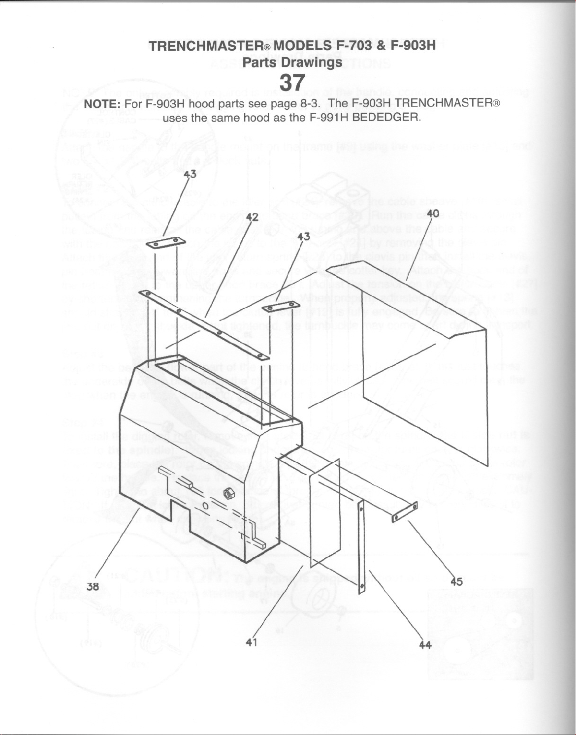
TRENCHMASTER@ MODELS F-703 & F-903H
Parts Drawings
37
NOTE: For F-903H hood parts see page 8-3. The F-903HTRENCHMASTER@
uses the same hood as the F-991H BEDEDGER.
42
~
44
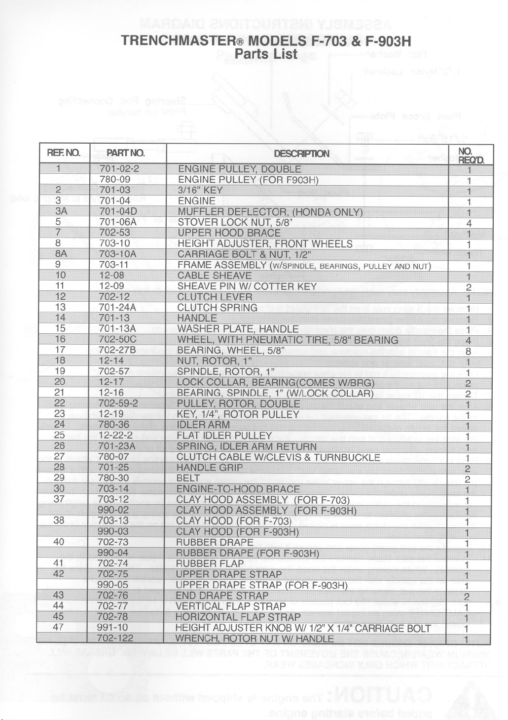
TRENCHMASTER@ MODELS F-703 & F-903H
Parts List
 Loading...