

Page 1
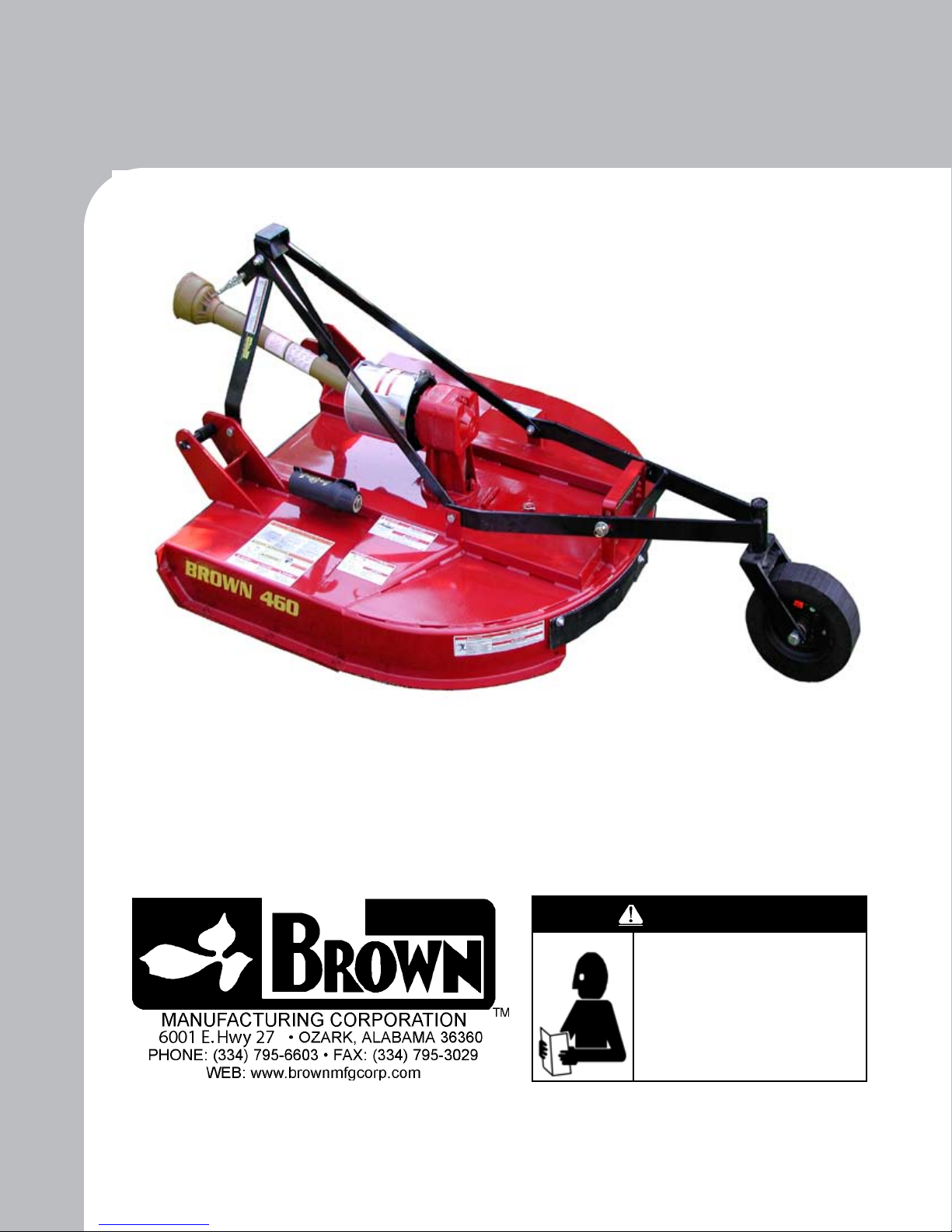
400 Series
Rotary Cutter
ATTENTION:
ALL WARRANTY WORK MUST BE APPROVED
BY BROWN MFG. CORP.
BEFORE WORK BEGINS
Owner / Operator Manual
WARNING
Before operating your machine,
stop and read this owners manual. Do not attempt to operate the
unit until you fully understand the
material covered in this manual.
Without the knowledge contained
in this manual, injury or death can
result.
Page 2

Copyright Infomation
Copyright ©2000 Brown Manufacturing Corporation, Ozark, Alabama. All photos and illustrations are
property of Brown Manufacting Corporation. “Texaco” and “Mobil” are trademarks of their respective companies. This publication may be freely reproduced, either in whole or in part, provided that
the content herein is not altered. We encourage you to make copies of this manual and to distribute
it to every operator of the machine. Additional copies are also available from Brown Manifacturing
Corporation.
Cover
Illustrated: Model 472 rotary mower.
Disclaimer
Due to engineering improvements and revision of product specications, the information contained in
this manual is subject to change without notice.
Page 3

Contents
Warranty ........................................................................................................................... 4
Registration ...................................................................................................................... 6
Equipment Safety ............................................................................................................. 7
Assembly........................................................................................................................ 16
Operation ........................................................................................................................ 18
Maintenance ................................................................................................................... 20
Troubleshooting ............................................................................................................. 30
Specications ................................................................................................................. 31
Replacement Parts .......................................................................................................... 32
Page 4

4
BROWN MANUFACTURING CORP.
Limited Warranty
1. LIMITED WARRANTIES
1.01. . Brown Manufacturing Corp. warrants for one year from the purchase date to the original non-commercial, governmental, or municipal purchaser (“Purchaser”) and warrants for ninety (90) days to the original commercial or industrial purchaser (“Purchaser”) that the
goods purchased are free from defects in material or workmanship.
1.02. Manufacturer will replace for the Purchaser any part or parts found, upon examination at its factory, to be defective under normal use
and service due to defects in material or workmanship.
1.03. This limited warranty does not apply to any part of the goods which has been subjected to improper or abnormal use, negligence,
alteration, modication, or accident, damaged due to lack of maintenance or use of wrong oil or expendable items such as blades, shields,
guards, or tires except as specically found in your Operator’s Manual.
1.04. Except herein, no employee, agent, Dealer, or other person is authorized to give warranties of any nature on behalf of the Manufacturer.
2. REMEDIES AND PROCEDURES
2.01. This limited warranty is not effective unless the Purchaser returns the Registration and Warranty Form to Manufacturer within 30
days of purchase.
2.02. Purchaser claims must be made in writing to the Authorized Dealer (“Dealer”) from whom Purchaser purchased the goods or an approved Authorized Dealer (“Dealer”) within 30 days after Purchaser learns of the facts on which the claim is based.
2.03. Purchaser is responsible for returning the goods in question to the Dealer.
2.04. If after examining the goods and/or parts in question, Manufacturer nds them to be defective under normal use and service due to
defects in material or workmanship, Manufacturer will:
(a) Repair or replace the defective goods or part(s) or
(b) Reimburse Purchaser for the cost of the part(s) and reasonable labor charges (as determined by Manufacturer) if Purchaser paid for the
repair and/or replacement prior to the nal determination of applicability of the warranty by Manufacturer. (The choice of remedy shall
belong to Manufacturer).
2.05. Purchaser is responsible for any labor charges exceeding a reasonable amount as determined by Manufacturer and for returning the
goods to the Dealer, whether or not the claim is approved. Purchaser is responsible for the transportation cost for the goods or part(s) from
the Dealer to the factory.
3. LIMITATION OF LIABILITY
3.01. . MANUFACTURER DISCLAIMS ANY EXPRESS (EXCEPT AS SET FORTH HEREIN) AND IMPLIED WARRANTIES FOR A
PARTICULAR PURPOSE.
3.02. MANUFACTURER MAKES NO WARRANTY AS TO THE DESIGN, CAPABILITY, CAPACITY, OR SUSTA INABILITY FOR
USE OF THE GOODS.
3.03. EXCEPT AS PROVIDED HEREIN, MANUFACTURER SHALL HAVE NO LIABILITY OR RESPONSIBILITY TO PURCHASER OR ANY OTHER PERSON OR ENTITY WITH RESPECT TO ANY LIABILITY, LOSS, OR DAMAGE CAUSED OR ALLEGED TO BE CAUSED DIRECTLY OR INDIRECTLY BY THE GOODS INCLUDING, BUT NOT LIMITED TO, ANY INDIRECT,
SPECIAL, CONSEQUENTIAL, OR INCIDENTAL DAMAGES RESULTING FROM THE USE OR OPERATION OF THE GOODS
OR ANY BREACH OF THIS WARRANTY. NOT WITHSTANDING THE ABOVE LIMITATIONS AND WARRANTIES, MANUFAC-
TURER’S LIABILITY HEREUNDER FOR DAMAGES INCURRED BY PURCHASER OR OTHERS SHALL NOT EXCEED THE
PRICE OF THE GOODS.
3.04. NO ACTION ARISING OUT OF ANY CLAIMED BREACH OF THIS WARRANTY OR TRANSACTIONS UNDER THIS WARRANTY MAY BE BROUGHT MORE THAN TWO (2) YEARS AFTER THE CAUSE OF ACTION HAS OCCURRED.
4. MISCELLANEOUS
4.01. Proper venue for any lawsuits arising from or related to this limited warranty shall be only in Dale County, Alabama.
4.02. Manufacturer may waive compliance with any of the terms of this limited warranty, but no waiver of any terms shall be deemed to
be a waiver of any other term.
4.03. If any provision of this limited warranty shall violate any applicable law and is held to be unenforceable, then the invalidity of such
provision shall not invalidate any other provisions herein.
4.04. Applicable law may provide rights and benets to Purchaser in addition to those provided herein.
KEEP FOR YOUR RECORDS (ATTENTION: READ YOUR OPERATOR’S MANUAL)
ATTENTION: Purchaser should ll in the blanks below for his reference when buying repair parts and/or for proper machine identica-
tion when applying for warranty.
Brown Implement Model _____________________________Serial Number__________________________
Date Purchased___________________________ Dealer__________________________________________
Brown Manufacturing Corp.
6001 E. Hwy 27
Ozark, AL 36360
800-633-8909
Page 5

TO THE OWNER/OPERATOR/DEALER
In addition to the standard Limited Warranty shown on the facing page, Brown Manufacturing Corp.
also provides:
1.) ONE-YEAR (12 months) {or 90 days for Commercial/Industrial Users} LIMITED WARRANTY
on the DRIVELINE components provided they have been properly maintained† and have not been
subjected to abuse or misuse.
2.) FIVE-YEAR (60 months) LIMITED WARRANTY* on GEARBOX components provided they
have been properly maintained† and have not been subjected to abuse or misuse except as limited
below.
* WARRANTY LIMITATIONS - GEARBOX
A) Warranty is ONE-YEAR (12 months) for Seals (After one year, seals are considered to be
WEARING PARTS and replacement is user’s responsibility).
B) User’s Gearboxes may be rebuilt by Brown Manufacturing Corp. or replaced by new or rebuilt
Gearboxes at the option of Brown Manufacturing Corp.
† NOTE — “properly maintained” specically includes, but is not limited to:
A) Running Gearboxes with the proper amount of the correct lubricant.
B) Adjusting Slip Clutches correctly to provide protection for Driveline and Gearbox
Components.
______________________________________________________________________________
5
To keep your implement running efciently and safely read your manual thoroughly and follow
these directions and the Safety Messages in this Manual. The Table of Contents clearly identies
each section where you can easily nd the information you need.
The OCCUPATIONAL SAFETY AND HEALTH ACT (1928.51 Subpart C) makes these minimum
safety requirements of tractor operators:
REQUIRED OF THE OWNER:
1. Provide a Roll-Over-Protective Structure that meets the requirements of this Standard, and
2. Provide Seatbelts that meet the requirements of this paragraph of this Standard and SAE J4C; and
3. Ensure that each employee uses such Seatbelt while the tractor is moving; and
4. Ensure that each employee tightens the Seatbelt sufciently to conne the employee to the protected provided by ROPS.
REQUIRED OF THE OPERATOR:
1. Securely fasten seatbelt if the tractor has a ROPS.
2. Where possible, avoid operating the tractor near ditches, embankments, and holes.
3. Reduce speed when turning, crossing slopes, and on rough, slick, or muddy surfaces.
4. Stay off slopes too steep for safe operation.
5. Watch where you are going — especially at row ends, on roads, and around trees.
6. Do not permit others to ride.
7. Operate the tractor smoothly — no jerky turns, starts, or stops.
8. Hitch only to the drawbar and hitch points recommended by the tractor manufacturer.
9. When the tractor is stopped, set brakes securely and use park lock, if available.
Page 6
Please complete the form below and mail to: Brown Mfg. Corp. - 6001 E. Hwy. 27 - Ozark, AL 36360
BROWN MANUFATUCTURING CORP. ® WARRANTY REGISTRATION INFORMATION
6
Brown Model ______________ Serial No._________ Purchase Date (mm/dd/yy) ___/___/____
Purchaser Last Name _____________________ First Name____________________ M.I._____
Street & No., RFD,
Box, &/or Apt. No._____________________________________________________________
City: _____________________________________ State or Province: _____ Zip __________
Dealer: ______________________________________________________________________
City: _____________________________________ State or Province_______ Zip___________
. I have informed the Purchaser of this product of Warranty terms, provisions, and procedures that
are applicable, reviewed the contents of the Operator’s Manual including safety equipment, safe
operation, and maintenance, reviewed the Safety Signs on implement (and tractor if possible), and
Purchaser’s responsibility to train his operators in safe operation.
. IMPLEMENTS: I have explained that Deectors, Chain Guards, or Solid Skirts must be maintained
in good repair and installed except in areas where persons, vehicles, livestock, or other property will
not be endangered by thrown objects and where such safety equipment would prevent the mower’s
reasonable performance of its assigned task.
. DRIVELINES: I have made certain that all driveline, gearbox, and other shields are in good repair
and fastened securely in place to prevent injuries from entanglement or thrown objects.
Dealer’s Signature: _______________________________________ Date:____________________
I have been instructed on the paragraphs above, received and have been instructed on the contents of
the Operator’s Manual including safety signs, safety equipment, safe operation, maintenance, and the
potential hazards of unauthorized alterations or modications of the product. I have been informed
of the warranty provisions and know that the warranty is not in effect until this form is received by
Brown Manufacturing Corp.
I understand the Implement Guarding statements above and the potential hazards of operating without such guards. I understand that the operator is responsible for the safety of others in the area. I
have examined the product and accept it as being complete and in satisfactory condition with all
required guards.
CUSTOMER COPY
Purchaser’s Signature:______________________________________ Date:__________________
PRE-DELIVERY SERVICE
CHECK AND ADJUST OR LUBRICATE AS REQURIED
See Operator’s Manual for Details
Inspection performed — Warranty and Safety Procedures Explained — Installation Complete
□ Gearbox (Oil Levels)
□ Wheel Hubs (Lubricate)
□ Wheel Hub Seals □ Tail Wheel Arm(s) (Height Adjustment)
□ Wheel Bearing (Check Grease and Preload)
□ Shredding Attachments □ Correct Blade Rotation Direction
□ Axle Arms and Beams
□ A-Frame Pivot and Links □ Cutting Height (Adjust Front to Rear)
□
Protective Shields (Operation and Installation) □ Driveline Clutch (Torque Limiter) (Adjust and
□ Safety Decals (Installed) □ Operator’s Manual (Supplied)
□ Tractor PTO Shield (Installed) □ S.M.V. Emblem (Installed if Needed)
CUSTOMER COPY
□ Drivelines (Proper Length and Lubrication)
□ Gearbox Vent Plugs (Location and Operation)
□ Deectors Front and Rear
□ All Bolts — Pins and Nuts (Proper Torque)
Run In)
Purchaser’s Signature______________________Date_________Dealer’s Signature________________________Date__________
Page 7
Please complete the form below and mail to: Brown Mfg. Corp. - 6001 E. Hwy. 27 - Ozark, AL 36360
BROWN MANUFATUCTURING CORP. ® WARRANTY REGISTRATION INFORMATION
7
Brown Model ______________ Serial No._________ Purchase Date (mm/dd/yy) ___/___/____
Purchaser Last Name _____________________ First Name____________________ M.I._____
Street & No., RFD,
Box, &/or Apt. No._____________________________________________________________
City: _____________________________________ State or Province: _____ Zip __________
Dealer: ______________________________________________________________________
City: _____________________________________ State or Province_______ Zip___________
. I have informed the Purchaser of this product of Warranty terms, provisions, and procedures that
are applicable, reviewed the contents of the Operator’s Manual including safety equipment, safe
operation, and maintenance, reviewed the Safety Signs on implement (and tractor if possible), and
Purchaser’s responsibility to train his operators in safe operation.
. IMPLEMENTS: I have explained that Deectors, Chain Guards, or Solid Skirts must be maintained
in good repair and installed except in areas where persons, vehicles, livestock, or other property will
not be endangered by thrown objects and where such safety equipment would prevent the mower’s
reasonable performance of its assigned task.
. DRIVELINES: I have made certain that all driveline, gearbox, and other shields are in good repair
and fastened securely in place to prevent injuries from entanglement or thrown objects.
Dealer’s Signature: _______________________________________ Date:____________________
I have been instructed on the paragraphs above, received and have been instructed on the contents of
the Operator’s Manual including safety signs, safety equipment, safe operation, maintenance, and the
potential hazards of unauthorized alterations or modications of the product. I have been informed
of the warranty provisions and know that the warranty is not in effect until this form is received by
Brown Manufacturing Corp.
I understand the Implement Guarding statements above and the potential hazards of operating without such guards. I understand that the operator is responsible for the safety of others in the area. I
have examined the product and accept it as being complete and in satisfactory condition with all
required guards.
CUSTOMER COPY
Purchaser’s Signature:______________________________________ Date:__________________
PRE-DELIVERY SERVICE
CHECK AND ADJUST OR LUBRICATE AS REQURIED
See Operator’s Manual for Details
Inspection performed — Warranty and Safety Procedures Explained — Installation Complete
□ Gearbox (Oil Levels)
□ Wheel Hubs (Lubricate)
□ Wheel Hub Seals □ Tail Wheel Arm(s) (Height Adjustment)
□ Wheel Bearing (Check Grease and Preload)
□ Shredding Attachments □ Correct Blade Rotation Direction
□ Axle Arms and Beams
□ A-Frame Pivot and Links □ Cutting Height (Adjust Front to Rear)
□
Protective Shields (Operation and Installation) □ Driveline Clutch (Torque Limiter) (Adjust and
□ Safety Decals (Installed) □ Operator’s Manual (Supplied)
□ Tractor PTO Shield (Installed) □ S.M.V. Emblem (Installed if Needed)
FILL OUT & RETURN
□ Drivelines (Proper Length and Lubrication)
□ Gearbox Vent Plugs (Location and Operation)
□ Deectors Front and Rear
□ All Bolts — Pins and Nuts (Proper Torque)
Run In)
Purchaser’s Signature______________________Date_________Dealer’s Signature________________________Date__________
Page 8
8
IMPORTANT NOTICE:
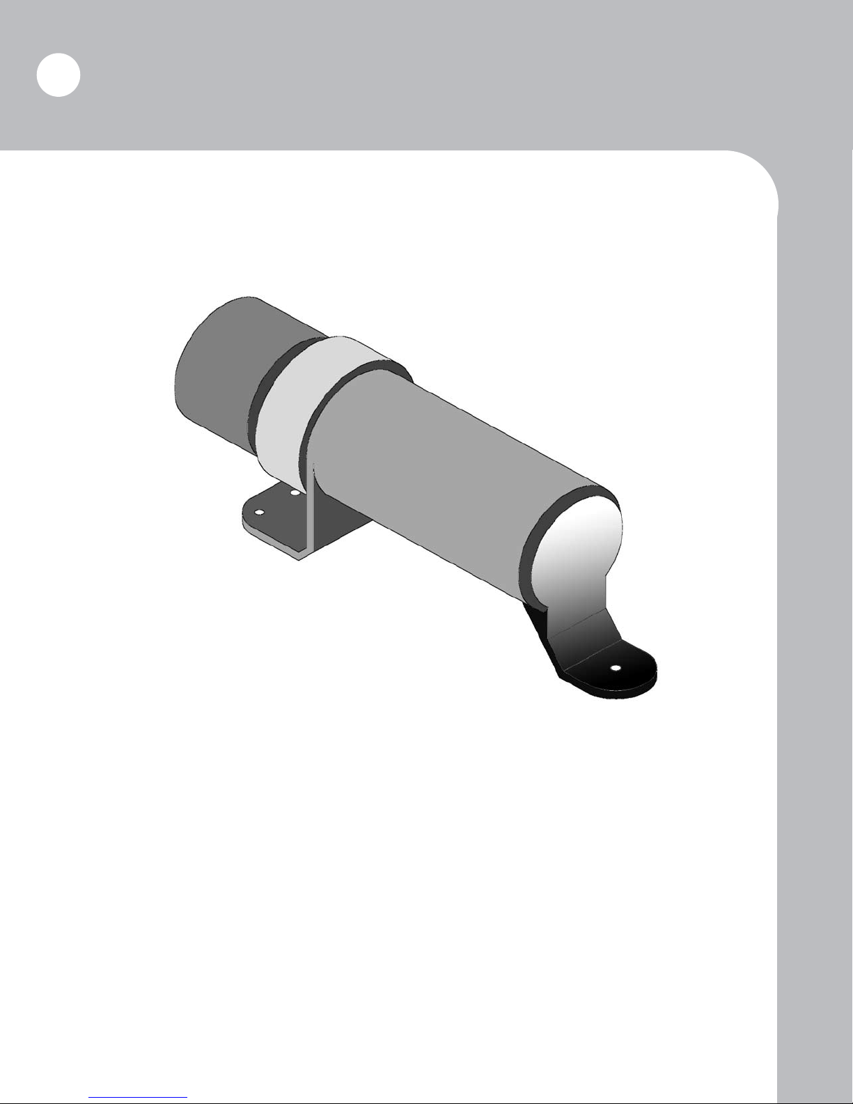
OWNER’S MANUAL STORAGE CONTAINER
* Brown Manufacturing provides an Owner’s Manual storage container on all equipment.
*This holder is mounted in a convenient location and provides the owner with the proper
safety and operation information.
*Two (2) copies are provided with each unit.
*One copy is for the owner to have at ofce for review when not operating the equipment.
*Second copy is to stay with the unit at all times. This will provide the operator the information needed for safe and proper operation of the unit.
*If the Owner’s Manual becomes lost or damaged, contact Brown Mfg. or your local Brown
dealer for free replacement.
Page 9
Equipment Safety
Warning: Read this manual before operation.
Operators of the equipment must read and understand this manual. Failure to read this manual and
follow these safety and operating instructions could result in serious bodily injury or even death.
WARNING
Before operating your machine, stop
and read this owners manual. Do
not attempt to operate the unit until
you fully understand the material
9
covered in this manual. Without the
knowledge contained in this manual,
injury or death can result.
Each operator of the equipment should review this manual every six (6) months. You are encouraged
to duplicate this manual and to distribute it to each operator of the equipment for their training and
reference. Additional copies are available from Brown Manufacturing Corporation.
IMPORTANT NOTICE:
OWNER’S MANUAL STORAGE CONTAINER
* Brown Manufacturing provides an Owner’s Manual storage container on all equipment.
*This holder is mounted in a convenient location and provides the owner with the proper safety and operation
information.
*Two (2) copies are provided with each unit.
*One copy is for the owner to have at ofce for review when not operating the equipment.
*Second copy is to stay with the unit at all times. This will provide the operator the information needed for
safe and proper operation of the unit.
*If the Owner’s Manual becomes lost or damaged, contact Brown Mfg. or your local Brown dealer for free
replacement.
Page 10
10
Equipment Safety
Recognize safety information
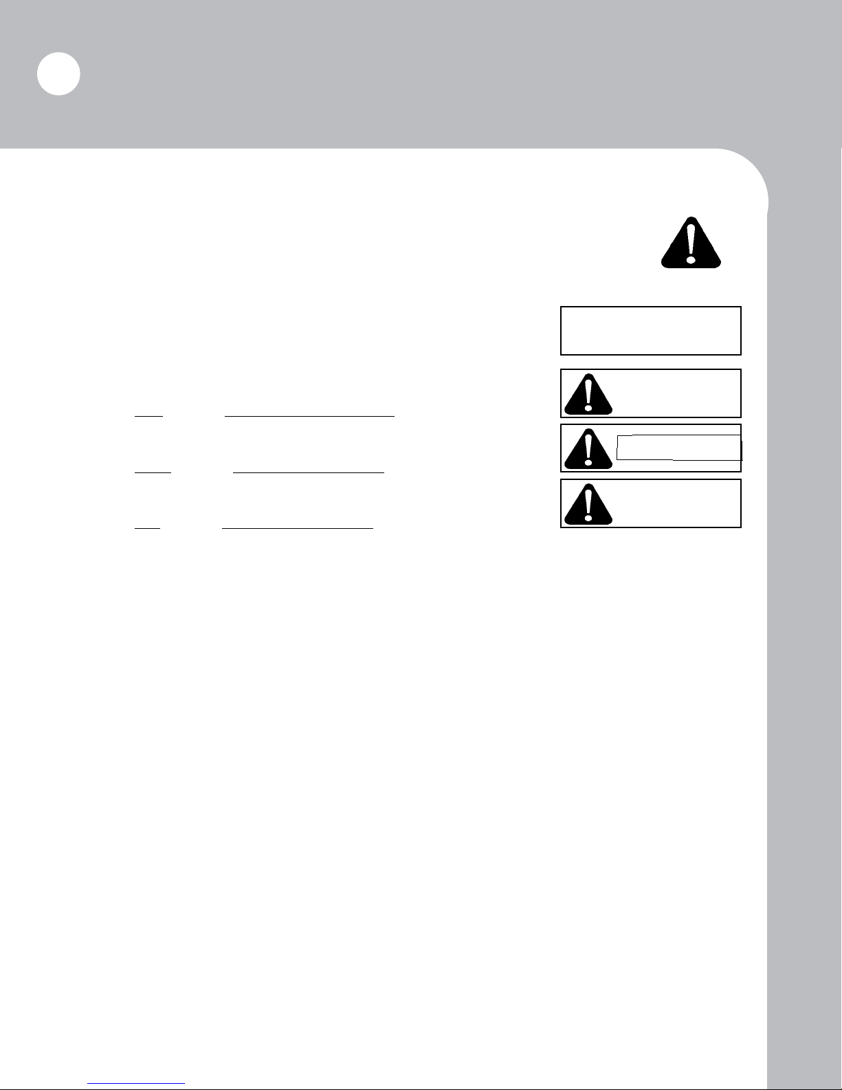
This is the safety alert symbol. When you see this symbol on your equipment or in this
manual, be alert to the potential for personal injury or injury to others.
Understand signal words
CAUTION used without the safety alert symbol indicates a potentially
hazardous situation which, if not avoided, may result in property damage.
CAUTION
CAUTION indicates a potentially hazardous situation which, if not
avoided, may result in minor or moderate injury.
WARNING indicates a potentially hazardous situation which, if not
avoided, could result in death or serious injury.
DANGER indicates an imminently hazardous situation which, if not
avoided, will result in death or serious injury.
CAUTION
WARNING
DANGER
Follow safety instructions
• Read owner/operator manual.
• Replace missing or damaged safety decals.
• Safety decals and this manual must be considered a permanent part of your equipment.
• Should ownership of the equipment be transferred, this manual must also be transferred.
• Unauthorized modications to the equipment are not recommended. This could impair the
function, safety, and life of the machine.
• For any part of this manual that you do not understand, contact your dealer or Brown Manufacturing Corporation at (800) 633-8909.
• All implements with moving parts are potentially dangerous. Due to this fact, there is no
substitute for a safe, knowledgeable operator. It is important that all persons operating this
equipment read, understand, and follow the instructions provided in this manual.
Page 11
Equipment Safety
Safety Decals
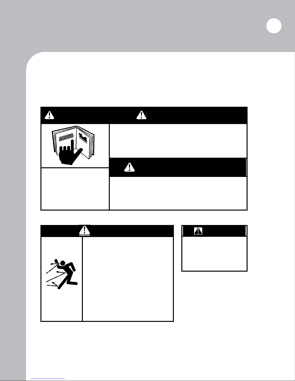
The following safety decals should be attached to the equipment at all times. Should any decals become
damaged or lost, it is the responsibility of the owner to replace it. Additional decals may be obtained
from the dealer or Brown Manufacturing Corporation.
11
WARNING
Read and understand
owner’s manual before operating unit.
Part No.: SD-010, All models.
DANGER
THROWN OBJECT HAZARD
To prevent serious injury or death
from thrown objects:
•Stay clear when blade is turning.
•Operate only with all guards
installed and in good condition.
•Stop operation if bystanders
come within several hundred feet.
ADVERTENCIA
Antes de probar la unidad por primera vez
deben remitirse a las instrucciones contenidas
en el manual.
ADVERTISSEMENT
S’assurer de bien comrendre toutes les
consignes du manuel de propriétarie avant
d’utiliser la unité.
WARNING
To prevent serious injury
or death:
•Operate only at 540 RPM
PTO.
•Keep guards and shields
in place.
SD-007A, Standard models*.
*All Brown 400 Series rotary
mowers are equipped for 540 RPM
PTOs as standard. Equipping for
1000 RPM PTOs is an option,
however; in such a case, use safety
decal SD-008A.
Part No.: SD-001A, All models.
Page 12
12
Equipment Safety
Safety Decals (continued)
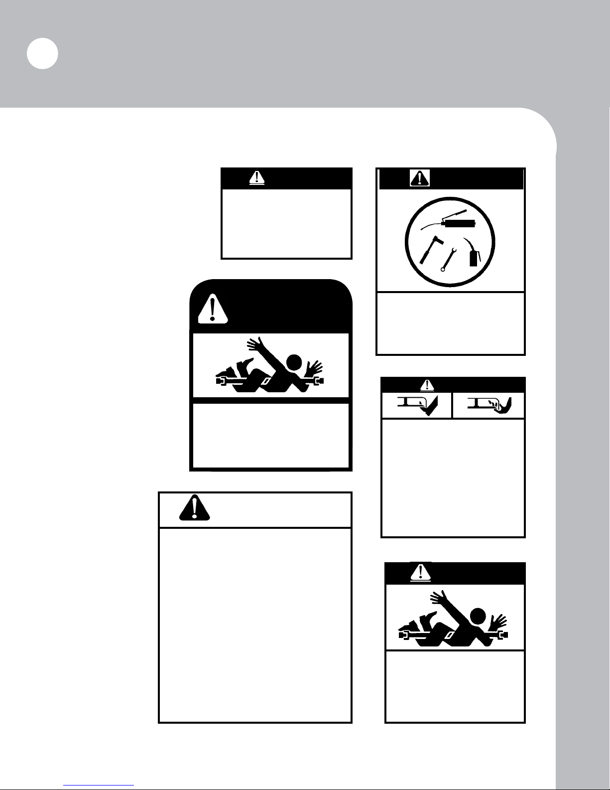
DANGER
Tighten blade bolts
as prescribed in
owner/operator’s
manual.
Part No.: SD-002, All models.
DANGER
SHIELD MISSING
DO NOT OPERATE
Part No.: DC-3-5-018, All models.
WARNING
To prevent serious injury or death:
•Read and understand Operator’s Manual
before using.
•Do not permit riders on the tractor or mower.
Never carry child on the tractor seat.
•Operate with guards installed and in good condition.
•Operate only with tractor equipped with ROPS
and seatbelts.
•Keep away from moving parts.
•Stop engine, set brake and wait for all moving parts
to stop before dismounting.
•Be sure lights and reectors required by law are
clean and in good working order before transporting.
•Do not allow children to operate mower.
•Travel with SMV and lights that follow local codes.
•Clear debris from mowing area.
•Do not operate in the raised position.
•Support securely before working beneath unit.
•Review safety instructions annually.
CAUTION
To Avoid Injury or Machine Damage:
•When servicing machine use
proper tools and equipment.
•Refer to operations manual for
instructions.
Part No.: SD-SW2, All models.
DANGER
ROTATING BLADES
To prevent serious injury or death
from rotating blades:
•Stay clear when blades are
turning or engine is running.
•Do not place hands or feet under
deck when the engine is running.
Part No.: SD-005A, All models.
DANGER
ROTATING DRIVELINE -
CONTACT CAN CAUSE DEATH
KEEP AWAY!
DO NOT OPERATE WITHOUT -
•All driveline guards, tractor and equipment
shields in place.
•Drivelines securely attached at both ends.
•Driveline guards that turn freely on driveline.
Part No.: SD-006A, All models.Part No.: SD-009A, All models.
Page 13
Equipment Safety
Safety Decals (continued)
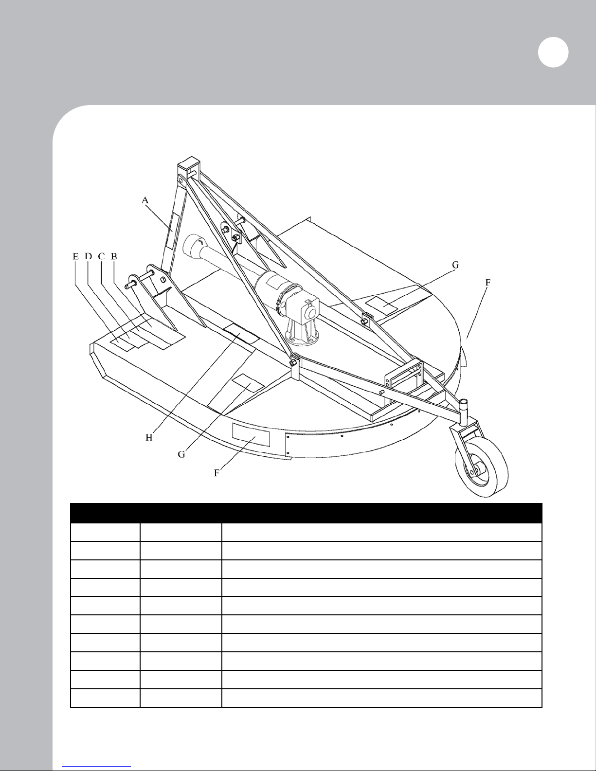
Safety decals must be positioned as illustrated below. Use this diagram to correctly identify missing,
damaged, or illegible decals for replacement.
13
Ref. No. Part No. Description
A SD-007A Safety Decal: Operate at 540 RPM PTO.
B SD-009A Safety Decal: (General safety issues.)
C SD-002 Safety Decal: Tighten blade bolts.
D SD-SW2 Safety Decal: When servicing, use proper tools and equipment.
E SD-010 Safety Decal: Read and understand owners manual.
F SD-001A Safety Decal: Thrown object hazard. (2 req.)
G SD-005A Safety Decal: Rotating blades. (2 req.)
H SD-006A Safety Decal: Rotating driveline.
Not pictured DC-3-5-018 Safety Decal: Shield missing (placed on drive shaft, under shields).
Not pictured SD-400 Complete safety decal set
Page 14
14
Equipment Safety
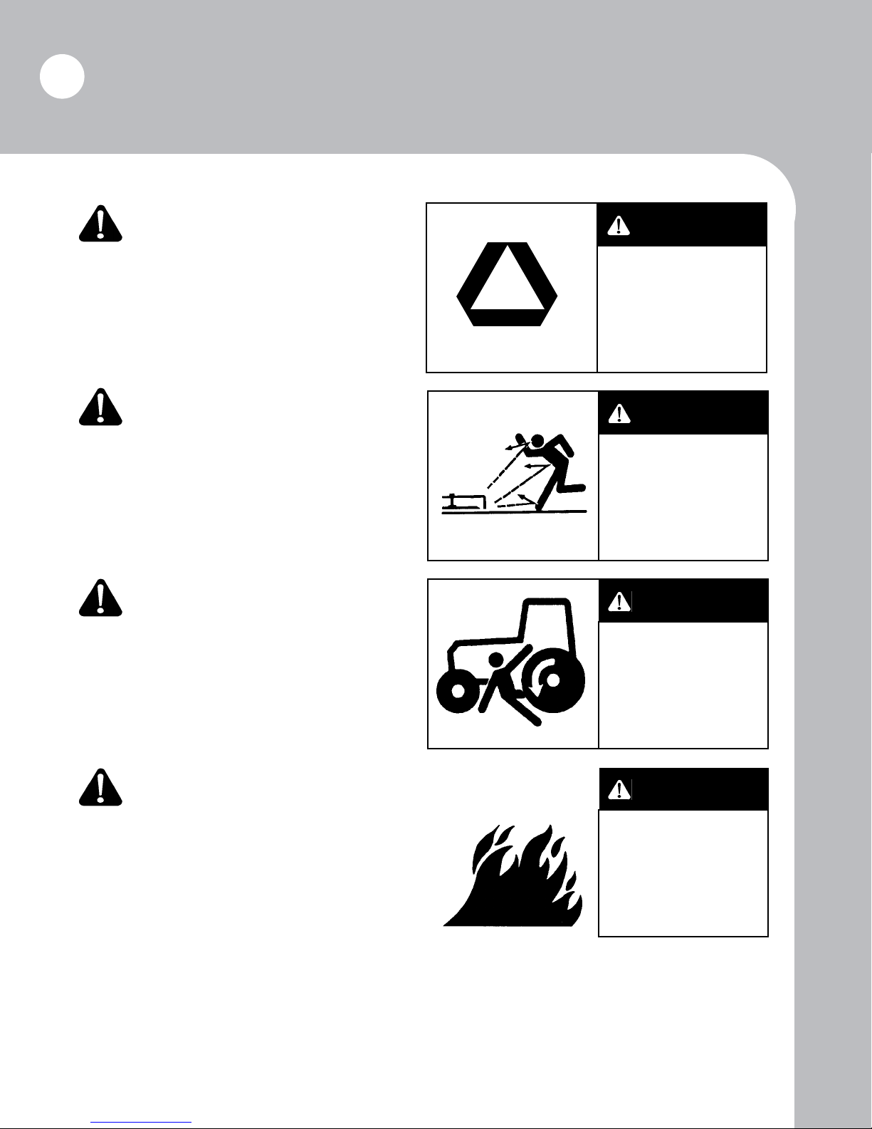
Warning! Transport with
care.
Before transporting to a new location, make certain
that the slow-moving vehicle (SMV) emblem is
installed and is clearly visible. Use ashing lights
and follow local trafc regulations.
Danger! Protect bystanders,
clear work area of debris.
Do not operate the mower near people. Debris can
be thrown hundreds of feet. Clear work area of
foreign objects such as wire, glass, and other debris.
Debris thrown by the mower can cause serious injury
or death.
Warning! Parking and dismounting.
The rotating parts of this mower continue to rotate
even after the PTO has been disengaged. The operator should remain seated until rotation has stopped.
He should then set the brake, turn off the engine,
and remove the key. See tractor manual for proper
parking procedure.
WARNING
Transport with care.
Use slow-moving
vehicle emblem
and ashing light.
Follow local
trafc regulations.
DANGER
Do not operate cutter near bystanders.
Clear work area of
debris before operating.
WARNING
Wait for all rotation
to stop before
dismounting
tractor.
Caution! Avoid res.
Keep the machine clean of debris, trash, and any
other ammable material.
CAUTION
K e e p m a c h i n e
clean of deb ri s.
Flammable debris
on machine poses
re hazard.
Page 15
Equipment Safety
15
Fire
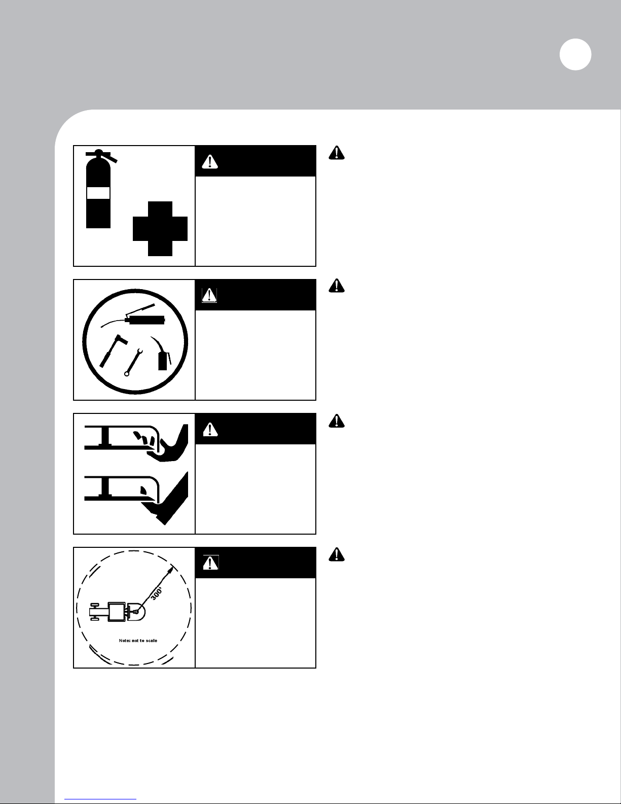
WARNING
Prepare for
emergencies.
Keep re extinguisher and rst
aid kit available.
WARNING
Check equipment
before operation.
Tighten all nuts
and bolts.
DANGER
Rotating blades.
Keep hands and
feet from under cutter deck.
Warning! Prepare for
emergencies.
Keep re extinguisher and rst aid kit available.
Inspect re extinguisher and check for charge
daily. Check rst aid kit for expired contents and
keep stocked.
Warning! Check
equipment before operating.
Tighten all nuts and bolts before operating. Make
certain that equipment is lowered to ground before attempting to make adjustments or perform
maintenance. Replace or repair any safety device,
bolts, etc., if damaged or worn.
Danger! Stay clear of
rotating blades.
The mower is designed to cut grass and brush up
to two inches in diameter. Keep hands and feet
from under mower deck!
Maintain safety distance of at least 300
ft. Failure to do so
may cause
serious injury or
death.
DANGER
Danger! Maintain safety
distance.
The mower creates a serious discharge hazard.
Always maintain a safety distance of at least
300 ft. Never operate mower with bystanders
present!
Page 16
16
Equipment Safety
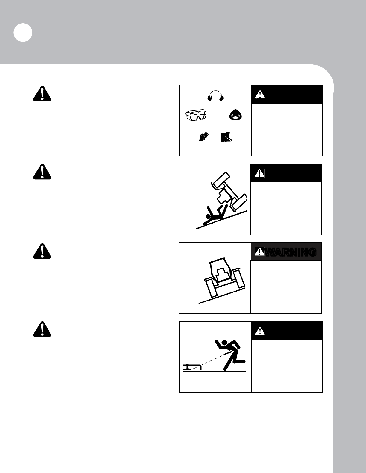
Warning! Wear protective
clothing.
Wear close-tting clothing and other protective
devices appropriate for the job.
Warning! Roll-over
protection.
Do not operate the mower on any tractor not
equipped with a certied roll-over protective structure (ROPS).
Warning! Slopes and
rough terrain.
When operating on slopes or rough terrain, decrease
travel speed. Do not operate in an area where the
tractor could roll over. Be sure to fasten safety
belt when operating tractor!
WARNING
Wea r pr ot e ct iv e
clothing.
WARNING
Use only with
tractors equipped
with a certied
roll-over protective
structure.
WARNING
Slow travel speed
when operating on
slopes or rough terrain.
Danger! Tighten blade
bolts.
Blade bolts will stretch with use and must be tightened. Follow maintenance instructions in this manual (see page 21). If the mower is operated with
loose blade bolts, blades and blade carrier will be
damaged. Operation with damaged blades and
blade carrier will lead to blade ejection and will
cause serious injury or death.
DANGER
Tighten blade bolts
as prescribed in
ow ne r s m an u al .
Ejection of blade
will cause serious
injury or death.
Page 17

Equipment Safety
17
DANGER
Riders can be
injured or killed.
Keep riders
off machine.
DANGER
Stay clear of
rotating drivelines.
Keep driveline
shields in place.
WARNING
Exe rc ise ca ut ion
while working under
cutter deck. Failure
to heed warnings
may lead to seious
injury or death.
Danger! Keep riders off
machine.
Riders can be seriously injured or killed by entanglement or by falling.
Danger! Stay clear of
rotating drivelines.
Entanglement in driveline can cause serious
injury or death. Keep driveline shields in place
at all times during operation. Driveline must turn
freely inside shields. Driveline shields must be
chained to prevent rotation.
Warning! Hazardous
service conditions.
While working under the mower deck, be aware
of safety hazards. Follow safety precautions
specied in this manual (see page 22). Failure
to exercise caution may lead to serious injury or
death.
Page 18
18
Assembly
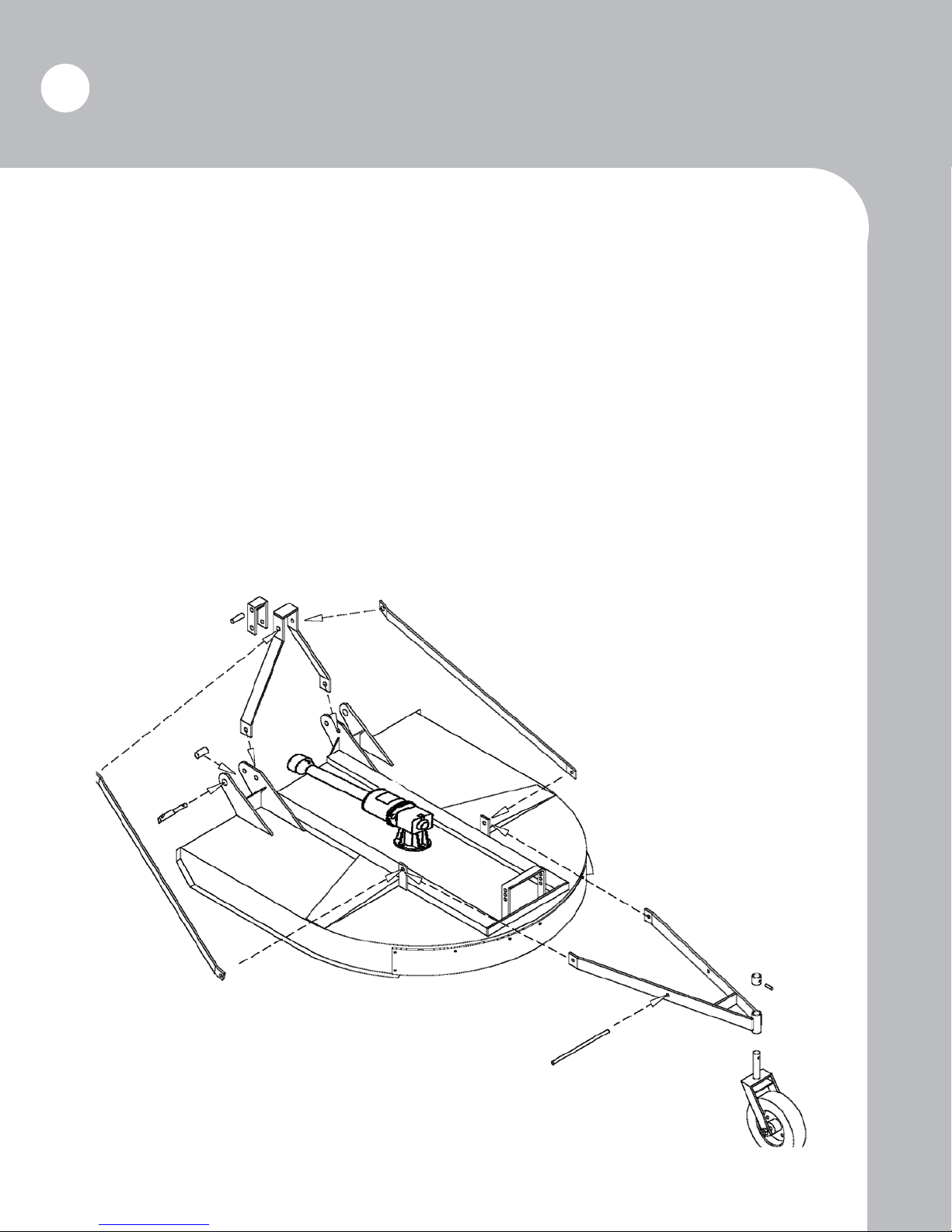
1. Fold tailwheel arms back from their shipping position toward the height adjustment brackets. Install
tailwheel stem into fork holder tube, placing collar over stem and inserting roll key through collar
and stem. Install height adjustment pin through arm and bracket. Assembly for models 472D and
484 is almost identical to that of the 460 and 472; the 472D and the 484 have twin tailwheels and
require this step to be completed twice.
2. Install A-frame on hitch brackets. Install A-frame braces to outside of front tailwheel brackets.
Remove bolt from top of A-frame and mount A-frame braces to outside surface of A-frame.
Note: Keep top toggle in position when reinstalling A-frame bolt.
3. Raise the mower with a tractor and properly adjust the tailwheel height. Next, reinstall lynch pins
into height adjustment pin.
4. Tighten all bolts securely.
Page 19

Assembly
5. Separate the male and female halves of the drive shaft. Apply heavy grease to the telescoping portion
of the male drive shaft; recouple the drive shaft.
6. Remove both bolts from the clutch hub. Slide the hub onto the input shaft of the gearbox. Be certain
that the lock pin snaps into the groove on the input shaft of the gearbox. Remove both lock bolts
from the clutch hub assembly. Slide the hub onto the input shaft of the gearbox. Align the groove
on the input shaft with the bolt holes on the hub. Reinstall the lock bolts and tighten securely. Re-
torque lock bolts on all models every hour for the rst eight hours of use. Failure to do so will
result in decreased life of the clutch hub and gearbox shaft splines.
7. Slide aluminum bell shield and bell shield clamp over drive shaft and attach bell shield to
mounting plate with the clamp. Adjust clamp as needed to assure proper attachment.
Warning! The driveline shield and bell shield must be kept in good operating condition.
Failure to maintain safety shields can result in injury or death.
19
8. Check the drive shaft for proper length:
a. Hitch the mower to the tractor.
b. Lift the mower to the tractor’s maximum lift position.
c. Measure the distance from the PTO of the tractor to the input shaft of the mower’s gear
box.
d. With the drive shaft compressed (pushed together fully), measure the overall length of the
shaft.
e. If the length of the compressed drive shaft is greater than the length between the PTO and
input shaft, then the drive shaft must be shortened to the latter length. Please note
that equal amounts must be removed from each section of the drive shaft.
Page 20
20
Operation
Before hitching mower to your tractor, make sure all safety devices are installed on both the mower
and the tractor.
Please follow all safety instructions and procedures.
STOP
Attach Equipment to Tractor.
Be sure the tractor is equipped with the correct category hitchpins, top link, etc. Be
extremely careful when positioning tractor to hitch to the equipment.
Caution! Never allow anyone between the tractor and the equipment during the hitching
process.
Be certain that the mower has been lubricated properly and check oil level in gear box prior to con-
necting driveline to tractor (See Page 24). Also, do not tighten the top link such that the ex-link
toggle is fully extended toward the tractor. The ex-link should be in a relaxed position when on
level ground.
Attach the driveline to the tractor. When attaching driveline to PTO shaft, be certain that the quick-
disconnect pin is properly seated in the groove of the tractor’s PTO shaft.
Warning! A loose driveline could disconnect and cause personal injury or property damage.
Adjust Cutting Height.
Warning! Be certain that tractor engine is stopped, key is removed, and all rotation of the mower
has ceased before making adjustments.
Caution! Avoid very low cutting heights. Striking the ground with blades causes a damaging shock
that can damage both the mower and the tractor.
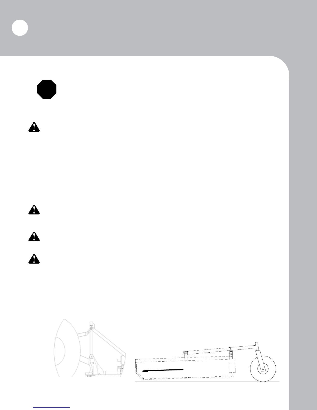
Using the tailwheel adjustment and the tractor’s lift arms, set the mower to the desired height; the mower
is designed to operate with a cutting height range between 2” and 12”. Note that, on level ground,
the front of the mower should be 1” below the rear (see illustration). Set the tractor’s lift stop at
the required position to maintain a uniform cut. The exible toggle should be in a relaxed posi-
tion, note Figure “A”.
Figure “A”
Front
1” above front
Page 21
Operation
Starting Mower
Power for operating the mower is supplied from the tractor PTO. Refer to your tractor manual for
instructions on engaging and disengaging the PTO.
Warning! Do not operate this mower unless the tractor has a live, or independent, PTO. The
momentum created by the blade carrier can push the tractor forward unexpectedly.
Warning! Operate mower only with the specied PTO RPM. Brown 400 Series mowers are de-
signed to operate at 540 RPM; however, a 1000 RPM design is an option.
Operating Speed
Proper operating speed for equipment will depend upon the height, density, and type of the material to
be cut. Regardless of chosen ground speed, always operate the PTO at the recommended RPM
when cutting.
21
General Operation
Warning! Avoid personal injury. Remove all rocks and other debris from work area before cut-
ting.
Observe the following guidelines when operating the mower:
• Do not back the mower into material, as this may bend
the mower deck.
• Never lower the mower onto material.
• Avoid tight turns near trees or stationary objects. The deck
may be damaged by side impact.
Remember: The safe operation of this equipment is the responsibility
of the operator. The operator should be familiar with both the tractor and the equipment. He must read and understand all applicable
operator manuals and follow all safety practices.
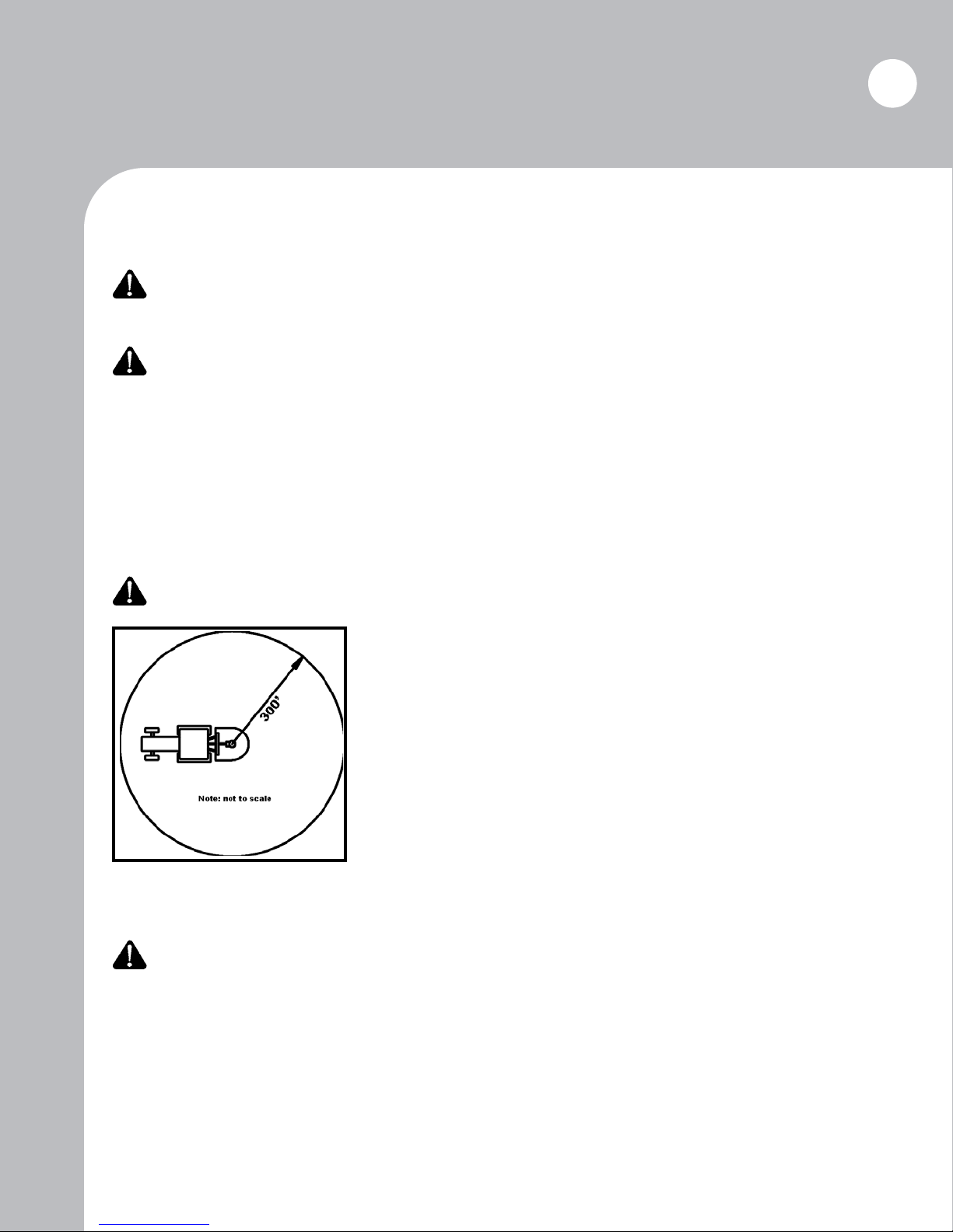
Warning! Avoid personal injury. Never operate machine around bystanders. Always maintain a
distance of at least 300 feet.
Page 22

22
Maintenance
Safety When Working Under Mower Deck
Never work under the mower deck until:
• the mower is sufciently braced and supported
• the tractor engine is off, brake is set, and key is removed
• PTO has been disengaged
• driveline is disconnected
• rear tractor tires have been secured with tire chocks
• the mower is cooled
Danger! Failure to follow these safety guidelines will result in serious injury or death.
Initial Maintenance
Warning! These maintenance practices must be followed every hour for the rst eight hours of
operation; the practices must also be performed every hour for the rst eight hours following the
removal/replacement of any of the components named in this section. Check daily thereafter.
1. Tighten the bolts holding the slip clutch to the input shaft of the gearbox.
Caution! Failure to tighten the keeper bolts will shorten the life of the slip clutch hub.
2. Check for debris deposited between the blade bar and the blades. Debris found jamming or locking the blades must be removed to insure that the blade may pivot freely on the blade bolt.
Danger! Failure to maintain freely pivoting blades will cause severe vibration or blade breakage
which will result in injury or death. Blades that are bent or deformed may not pivot and must be
replace.
3. Tighten blade bolts and blade bar nut. See tightening blade bolt section on Page 23.
Warning! Failure to tighten blade bolts and blade bar nut can cause blade bolts, blades, or output
shafts to break, which can result in injury or death.
4. Check for debris deposited around the output shaft or tailwheel axle.
5. Tighten gearbox mounting bolts.
Caution! Failure to keep the gearbox bolts tightened can cause the blades to strike the bottom of
the mower deck or break the output shaft of the gearbox.
Page 23

Maintenance
Daily Maintenance
1. Repeat all steps listed under the “Initial Maintenance” section on a daily basis after the initial
maintenance has
been performed.
2. Lubricate the driveshaft tubes and U-joint.
3. Lubricate the tailwheel hub.
4. Check and maintain the proper amount of lubricant in the gearbox. The recommended lubri-
cant for the gearbox is cottonpicker spindle grease.
5. Check the blades; sharpen or replace as necessary.
Warning! Use only blades and blade bolts supplied by Brown Manufacturing Corporation. Only
Brown has access to the engineering and test data necessary to produce a high-quality blade that meets
all safety and quality requirements.
Warning! If the blades must be sharpened, follow the proper safety procedures listed on page 22
of this manual for working under the mower deck.
23
Tightening Blade Bolts
Tighten blade bolts each hour for the rst eight hours of use; tighten daily thereafter. Repeat hourly
inspections each time the blades are removed/replaced.
Danger! Blade bolts will stretch with use and must be tightened. Allowing blade bolts to run
loose will damage bottom of blade carrier and will lead to jammed blades. Loose or jammed blades
can and will cause serious injury or death.
1. Disengage PTO; be certain that all rotation has stopped.
2. Lift mower high enough to place suitable supports under the mower deck.
3. Turn tractor engine off; remove key; lock transmission and brakes; chock rear wheels.
4. Disconnect driveline.
5.
Use a pipe wrench to hold the blade bolt; torque blade bolt nut using a 1 11/16” 6 point socket to approximately 600 to 700 ft./lbs. Blades must pivot freely after tightening; check for jammed blades.
6. Remove blade bar cotter pin and tighten nut with a 1½” socket. Torque nut to 700 ft./lbs.; con-
tinue to torque until cotter pin hole aligns with nut. Install a new cotter pin. Never loosen nut to
align cotter pin hole; always tighten to next alignment slot.
Warning! Failure to keep blade bolts tight can and will cause: blade breakage; warping of blade
bar; ejection of blade from mower. These hazards can cause serious injury or death.
If blade bolts are allowed to run loose, the obvious danger is for the bolt to come completely loose,
allowing the blade, bolt, and nut to be ejected from the mower.
(continued on next page)
Page 24
24
Maintenance
Tightening Blade Bolts (continued)
The second danger is that when the bolt is not sufciently tight, the blade is allowed excess vertical
movement when it strikes an object, be it something it will cut or something into which it should not
come in contact. In this situation, the blade is being hammered against the blade carrier and exed,
or bent, up around the edge of the blade carrier at least twelve (12) times per second, generally fteen
(15) times per second. This situation will cause the blade to break from fatigue and to be ejected from
the mower.
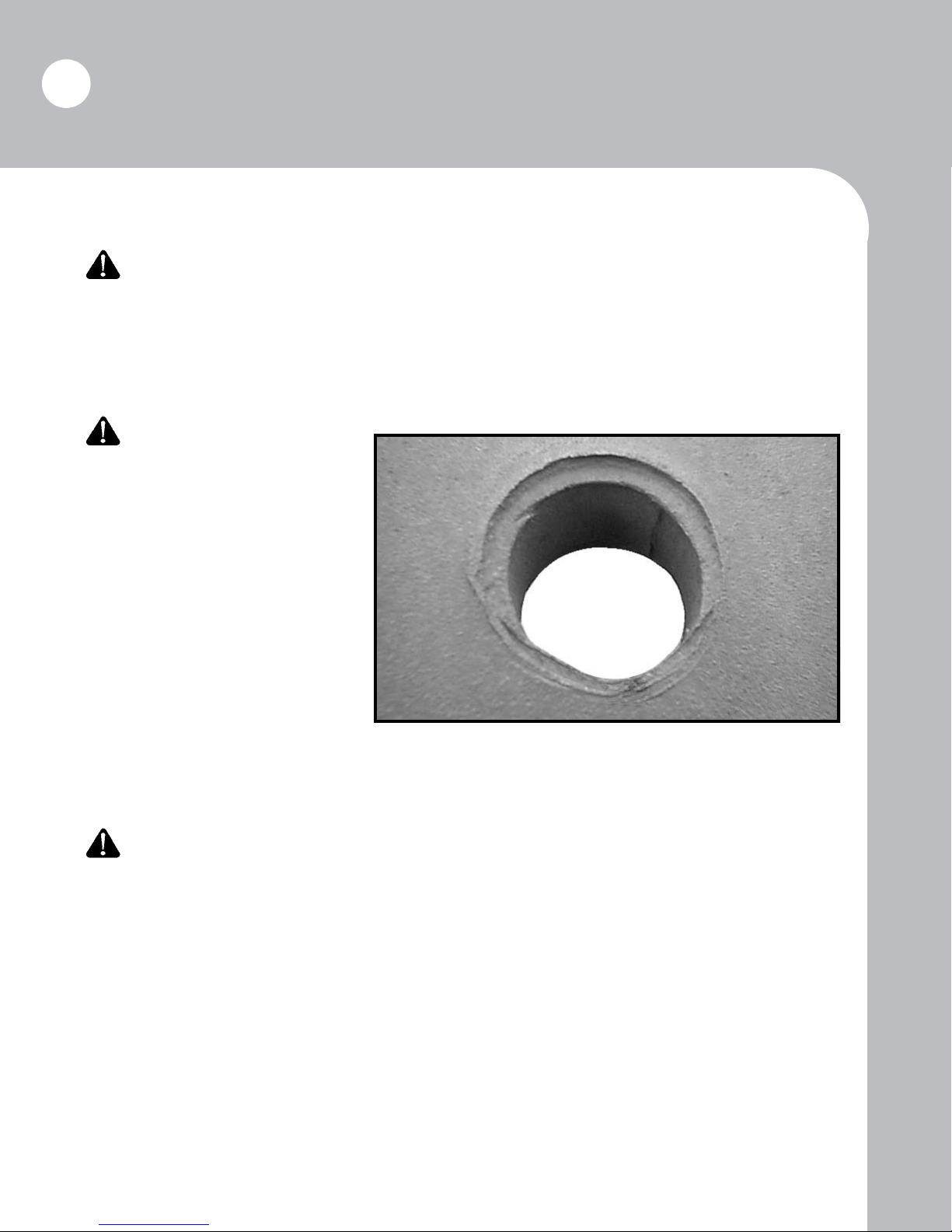
The third danger is that, while
the second situation is ocurring, the
blade bolt is also hammering the
underside of the blade carrier; the
shoulder of the blade bolt beats an
indention around the blade bolt hole
into which the bolt shoulder will t.
When this damage occurs, the blade
bolt will pull up into the indention
when the bolt is tightened, causing
the blade to jam so that it can no longer pivot on the blade bolt. A jammed
blade will break either from fatigue or
from catostrophic occurance and will
allow the blade to be ejected. A blade carrier damaged in this manner must be taken out of service immediately. Repair the blade carrier (contact Brown Mfg. Corp. for instructions) and replace the blades
and blade bolts before returning the machine to service.
All three of the described occurances will cause the blades to break and be ejected. An ejected
blade can and will cause serious injury or death.
REMEMBER: Blades must pivot freely and blade bolts must be tight!
Proper Gearbox Lubrication
On level ground, remove the 1/8” (lower) pipe plug from the rear of the gearbox housing. If the oil
level is not at the 1/8” port, oil must be added. Remove the 1/2” (upper) vent plug from the housing
and add the recommended lubricant (cottonpicker spindle grease) until the oil level reaches the lower
port. Make certain both plugs are replaced and tightened securely before operating.
Page 25
Maintenance
Slip Clutch Adjustment
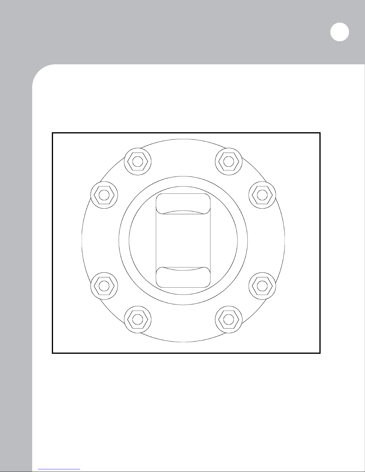
Check the slip clutch regularly; tighten the spring bolts if necessary. When tightening clutch bolts,
torque the bolt nuts in sequence, as illustrated. Incrementally torque each bolt nut until each clutch
spring measures 1” to 1-1/32” in length.
1 8
6 3
25
4 5
7 2
Page 26
26
Maintenance
Maintenance/Repair Log
Please record all maintenance and repair services performed on the mower. This log may help identify
reoccuring problems with your mower and may be requested by the manufacturer when making warranty claims. Additional log pages may be copied or ordered from Brown Mfg. Corp.
Date Function Part(s) Involved Initials
Initial Maintenance
· 1
¸ 2
st
Hour
nd
Hour
¹ 3rd Hour
º 4th Hour
th
» 5
Hour
¼ 6th Hour
th
½ 7
Hour
¾ 8th Hour
slip clutch, gearbox, blades, blade
bolts, blade bar nut
Page 27
Maintenance
Maintenance/Repair Log (continued)
Date Function Part(s) Involved Initials
27
Page 28

28
Troubleshooting
Problem Possible Cause(s) Possible Solution(s)
Excessive vibration 1. Loose gearbox bolts
2. Loose blade bar and/or blade bolts
3. Blades are not freely swinging
4. Broken, bent, or warped blades
5. Blade bar not seated properly on
shaft
6. Blades not paired by weight
Excessive clutch slippage 1. Worn clutch linings or plates
2. Oil on lining
3. Glazed friction lining
4. Excessive force on clutch
5. Dull Blades
Overheating gearbox 1. Insufcient lubricant level
2. Improper lubricant
3. Debris build-up around gearbox
4. Bearing or gears set improperly
Noisy gearbox 1. Rough gears
2. Worn bearings
3. Insufcent lube level
1. Tighten bolts
2. Tighten blade bar nut or blade bolt nuts
3. Clear blade of obstruction or repair
blade carrier (see page 21)
4. Replace set of blades and bolts
5. Remove blade bar; clean hub and
shaft; reseat
6. Check blades for equal weight
1. Repair clutch
2. Replace linings
3. Clean with emory cloth
4. Reduce ground speed, material intake,
or tractor size
5. Resharpen or replace
1. Fill to full level
2. Replace with correct lubricant
3. Remove debris
4. Consult dealer
1. Run for a short break-in period or
replace gears
2. Replace bearing
3. Add lube.
Leaking gearbox 1. Damaged oil seal
2. Bent shaft
3. Oil seal installed incorrectly
4. Oil level too high
5. Shaft rough or pitted in oil seal
area
6. Shaft bore worn in casting
7. Damaged gasket
8. Loose bolts
Short blade life 1. Cutting too low
2. Cutting in sandy or rocky condi-
tions
3. Inadequate blades
4. Ground speed too fast
Not cutting clean 1. Dull blades
2. Insufcient PTO speed
3. Cutter not level
4. Ground speed too fast
5. Blades are not freely swinging
6. Low engine RPM
1. Replace seal
2. Replace seal and shaft
3. Replace seal
4. Drain oil to proper level
5. Replace shaft
6. Replace casting or gearbox
7. Replace gasket
8. Tighten bolts.
1. Increase cutting height
2. Increase cutting height
3. Replace with Brown blades
4. Slow ground speed
1. Sharpen or replace blades
2. Use correct PTO speed
3. Adjust cutter
4. Reduce ground speed
5. Clear blade of obstruction
6. Increase tractor RPM
Page 29
Specications
29
Cutting
Model Gearbox
460 120 HP 60” 1 5 900 lbs. 2-disc Category I/II
472 120 HP 72” 1 5 1060 lbs. 2-disc Category I/II
472D 120 HP 72” 2 5 1180 lbs. 2-disc Category I/II
484 120 HP 84” 2 6 1375 lbs. 4-disc Category II
Standard Features
Reinforced round-back deck design
All welded, 7 ga. (3/16”) steel deck
2 free-swinging blades, 1/2” x 4” high-tensile, updraft
Flexible, 3-point A-frame with clevis-style hitch
Width Tailwheels
Driveshaft
Size Weight
Slip
Clutch Hitch
2” to 12” cut height
1 : 1.46 gear ratio
7 ga. (3/16”) round disc stump jumper with 1” x 5” bar
1/4” x 2” replaceable steel slides (M-484: 3/8” x 2”)
Replaceable front & rear rubber deectors
Options Part No.
For 460: 4-007
Front 5/16” chain curtain deector
Rear 5/16” chain curtain deector
For 472: 4-009
For 484: 4-011
For 460: 4-008
For 472: 4-010
For 484: 4-012
Page 30
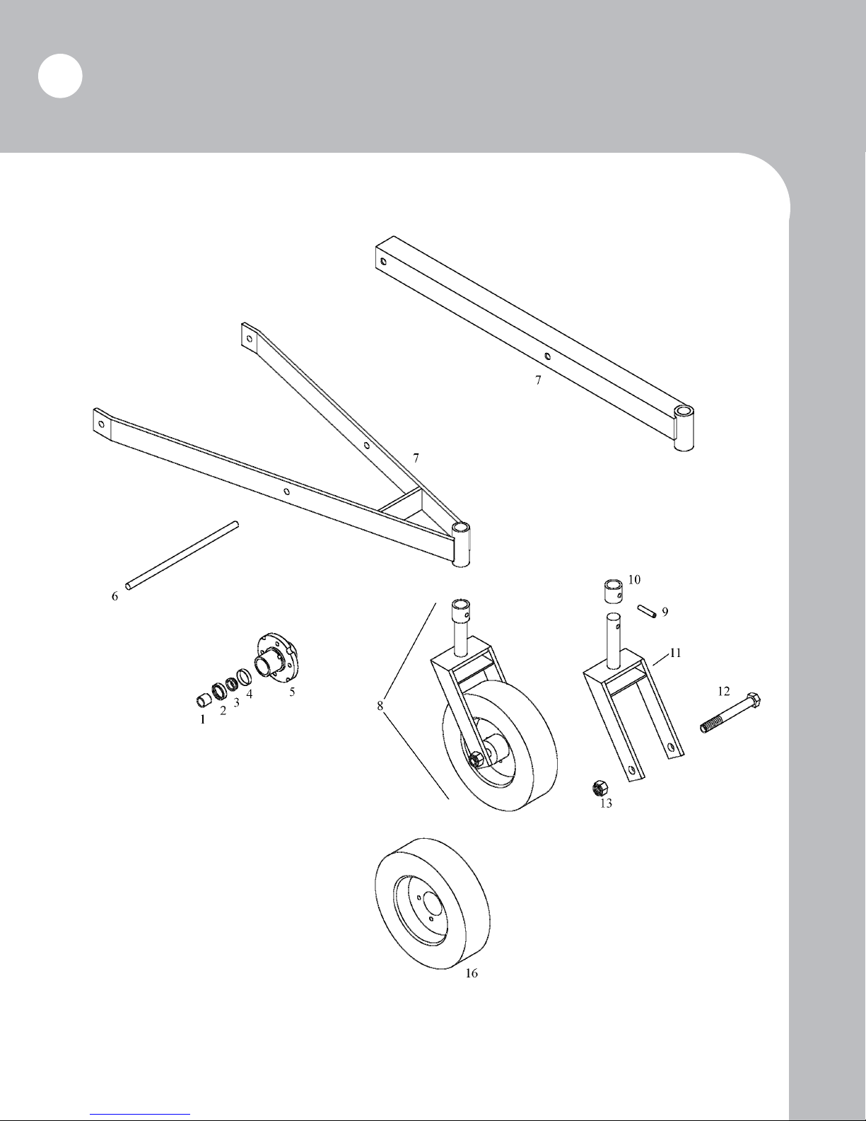
30
Tailwheel Assembly
Replacement Parts
Page 31
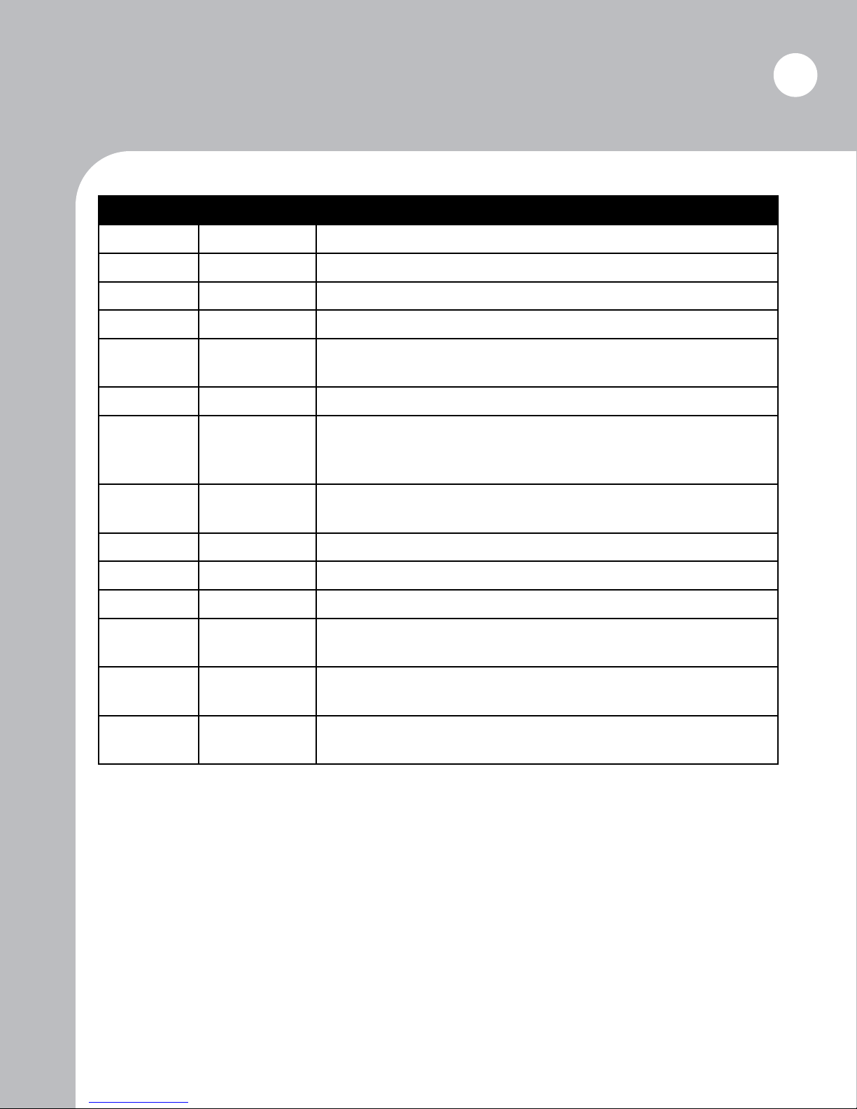
Replacement Parts
Tailwheel Assembly (continued)
Ref. No. Part No. Description
1 67-S Spacer (pair)
2 64-T Seal (2 req. per tailwheel)
3 65-T Bearing (2 req. per tailwheel)
4 65-C Cup (2 req. per tailwheel)
31
5 67T
67T-A
6 4-024 Height adjustment pin with clips
7 4-014
4-015
4-016
8 4-032 Complete tailwheel assembly
9 61-D Roll pin
10 61-C Collar
11 4-013 Fork
12 4-033 Axle
13 4-034 Axle nut
16 69-A Tire and wheel assembly
Tailwheel hub only with cups and lug bolts
Complete tailwheel hub assembly
460: Tailwheel arm with fork holder
472: Tailwheel arm with fork holder
472D, 484: Tailwheel arm with fork holder
Page 32
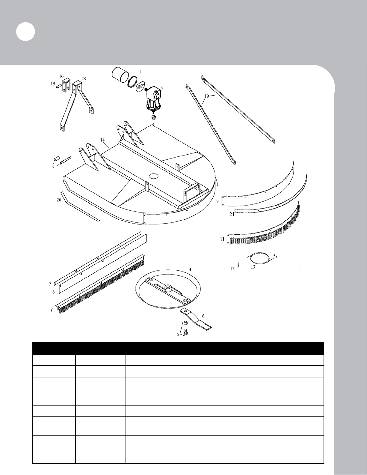
32
Deck Assembly
Replacement Parts
Ref. No. Part No. Description
1 232-0028 Bell Shield Assembly
3 235-0001 120 HP gearbox
4 4-021
4-022
4-023 (NLA)
5 TC-133KL Blade bolt assembly
6 500-27A
4-029A
7 4-001S
4-002S
4-003S
460: Stump jumper
472, 484 after s/n 1192: Stump jumper
484 through s/n 1192: Stump jumper (use 4-022 with 4-029A blades)
460, 472, 484 through s/n 1192: Blade
484 after s/n 1192: Blade
460: Metal strap
472: Metal strap
484: Metal strap
Page 33
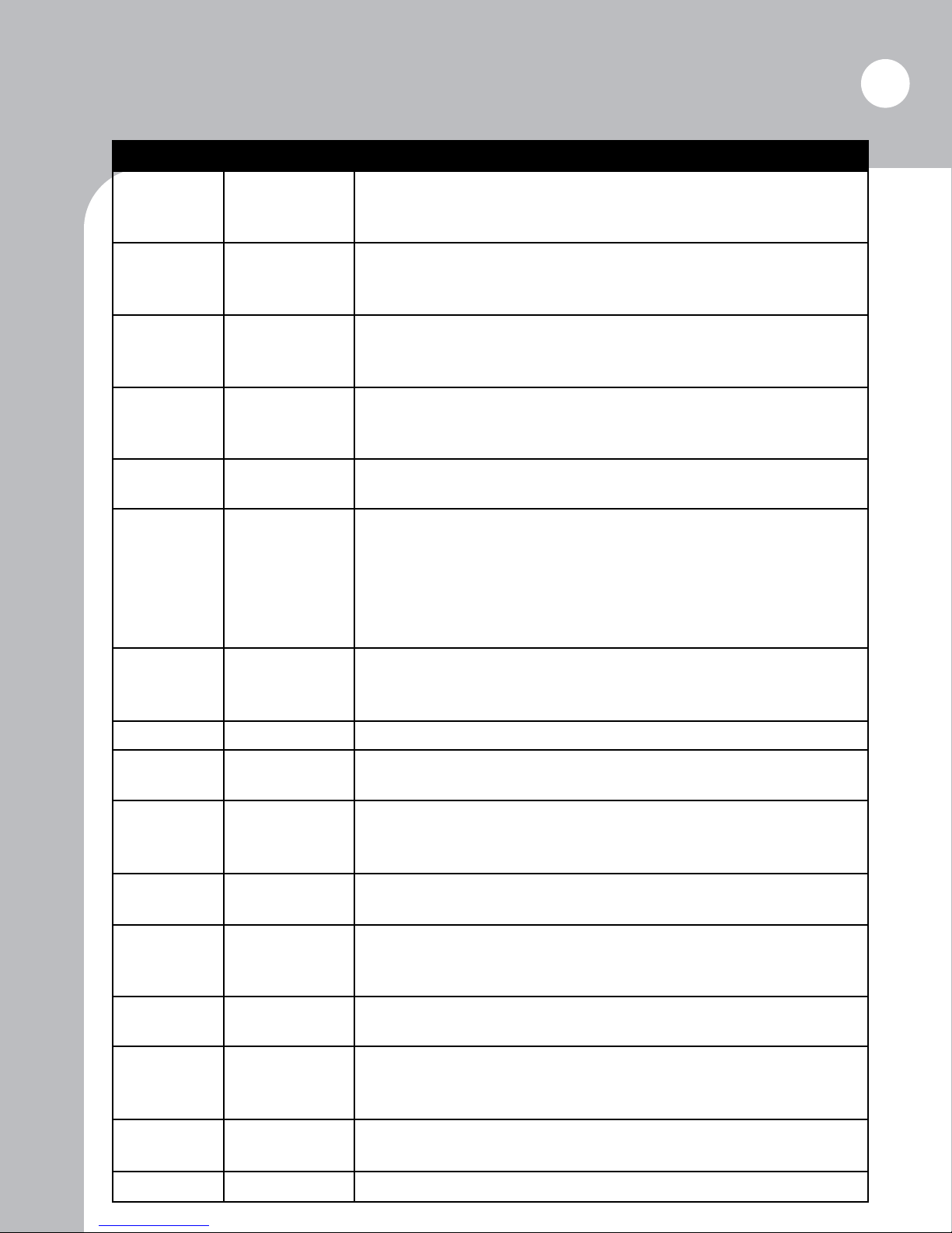
Replacement Parts
Deck Assembly (continued)
Ref. No. Part No. Description
33
8 4-001
4-002
4-003
9 4-004
4-005
4-006
10 4-007
4-009
4-011
11 4-008
4-010
4-012
12 TC2-009
TC2-010
13 4-007C
4-008C
4-009C
4-010C
4-011C
4-012C
460: Rubber front deector
472: Rubber front deector
484: Rubber front deector
460: Rubber rear deector
472: Rubber rear deector
484: Rubber rear deector
460: Chain front deector
472: Chain front deector
484: Chain front deector
460: Chain rear deector
472: Chain rear deector
484: Chain rear deector
Front chain links (5 pcs.)
Rear chain links (4 pcs.)
460: Front cable with clamps
460: Rear cable with clamps
472: Front cable with clamps
472: Rear cable with clamps
484: Front cable with clamps
484: Rear cable with clamps
14 4-035A
4-030A
4-031A
15 DH-1254A Spacer
16 4-025
4-025B
17 4-095
4-095S
TC-126
18 4-017
4-018
19 4-026
4-027
4-028
20 4-019
4-020
21 4-004S
4-005S
4-006S
460: Deck
472: Deck
484: Deck
460: Category I toggle
472, 484: Category II toggle
460, 472: Category I/II lift pin with spacer & lynch pin
460, 472: Lift pin spacer
484: Category II lift pin with lynch pin
460, 472: A-frame
484: A-frame
460: A-frame brace
472: A-frame brace
484: A-frame brace
460, 472: Slide with plow bolts, lock washer, and nuts
484: Slide with plow bolts, lock washer, and nuts
460: Metal strap
472: Metal strap
484: Metal strap
Not pictured 500-021
500-022
Not pictured TC-126A 7/16” lynch pin
460: Category I top pin with lynch pin
472, 484: Category II top pin with lynch pin
Page 34
34
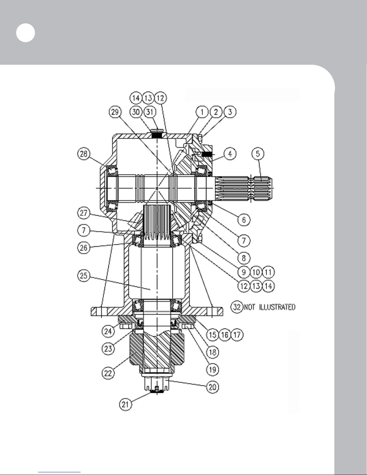
Replacement Parts
120HP Gearbox
NOTE: Gearbox for all cutters having a serial number with second character
being a “B”: Example: 5B-XXXX
Ordering replacement parts
Please contact the nearest Brown dealer for replacement parts. They will be able to meet most of your
equipment needs.
Page 35
Replacement Parts
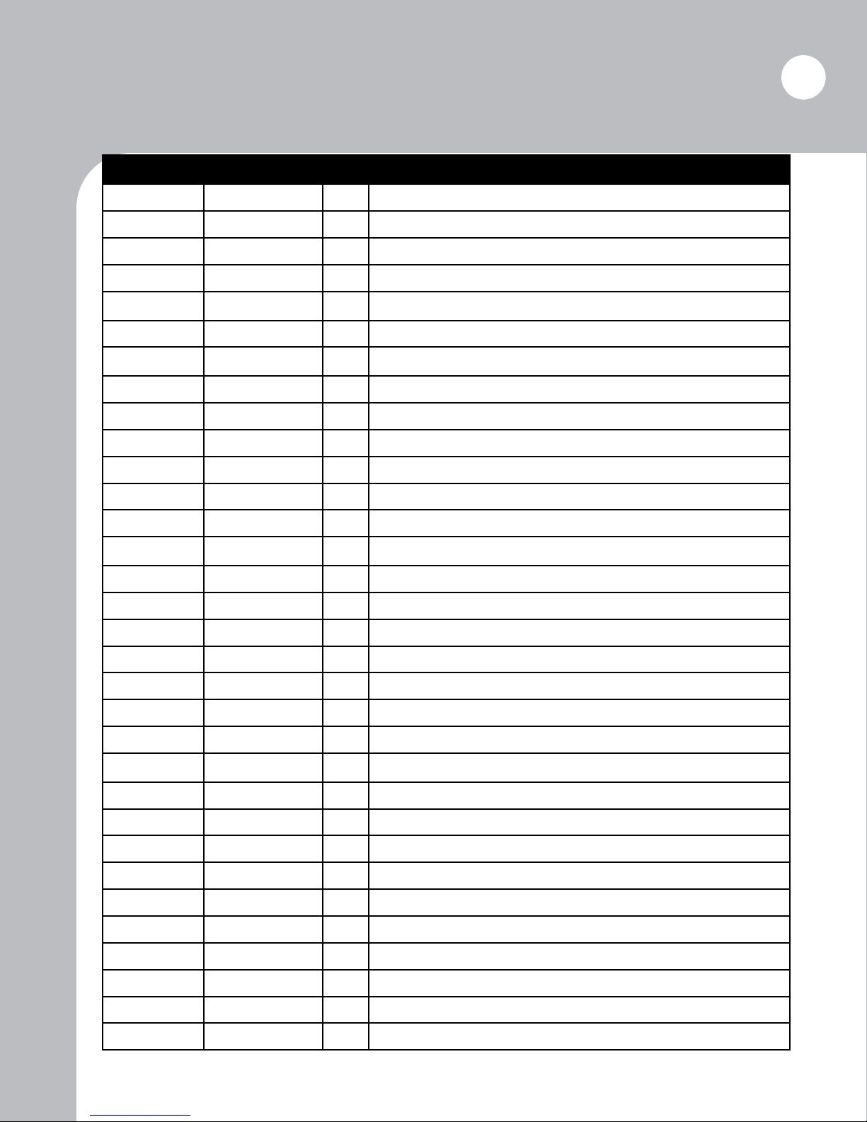
120HP Gearbox (continued)
Ref. No. Part No. Qty. Description
1 235-0003 1 Housing
2 MLW10 8 M10 Lock Washer
3 MCS10C30 8 M10 X 1.5 X 30 Hex Head Cap Screw
4 235-0004 1 Input Cap
5 235-0005 1 Input Shaft
6 WHD-202-20 1 Input Oilseal
7 235-0006 2 Spacer
8 235-0007 1 19 Tooth Gear, Input
9 235-0008 VAR Input Cap Gasket (0.15)
10 235-0009 VAR Input Cap Gasket (0.25)
11 235-0010 VAR Input Cap Gasket (0.45)
35
12 235-0023 VAR Shim (0.40)
13 235-0024 VAR Shim (0.30)
14 235-0025 VAR Shim (0.50)
15 235-0026 VAR Output Cap Gasket (0.15)
16 235-0027 VAR Output Cap Gasket (0.25)
17 235-0028 VAR Output Cap Gasket (0.45)
18 MLW12 4 M12 Lockwasher
19 MCS12C38 4 M12 x 1.75 x 38 Hex Head Cap Screw
20 TC-134F 1 1” - 14 Flanged Hex Nut
21 TC-135 1 Cotter Pin
22 TC-010 1 2 1/2” Blade Hub
23 235-0013 1 Output Oilseal
24 235-0014 1 Output Cap
25 235-0015 1 Output Shaft
26 235-0016 2 Bearing Assembly
27 235-0017 1 13 Tooth Gear, Output
28 235-0018 2 Bearing Assembly
29 235-0019 1 Retaining Ring
30 235-0020 3 Sealing Washer
31 235-0021 2 M18 Drain Plug
32 235-0022 1 M18 Vent Plug
Page 36
36
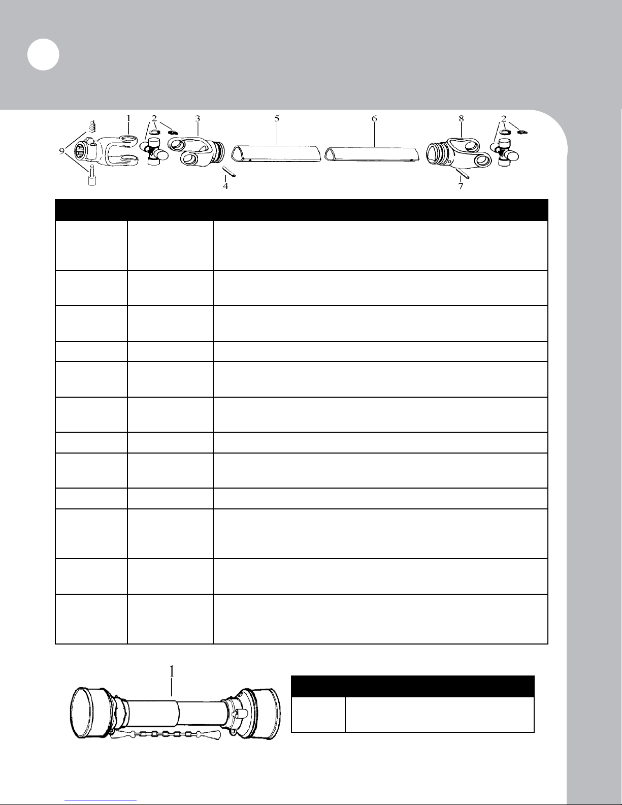
Replacement Parts (Driveline)
Ref. No. Part No. Description
1 4-050
TC-304
TC-304A
2 4-051
TC-305
3 4-052
TC-306
4 TC-307 Roll key
5 4-053
TC-309A
6 4-054
TC-311A
7 TC-312 Roll key
8 4-055
TC-313
9 484QDK Pin kit
Not pictured 4-056
4-057
4-057-1000
460, 472: Quick-hitch yoke
484 (540 RPM): Quick-hitch yoke
484 (1000 RPM): Quick-hitch yoke
460, 472: U-joint kit
484: U-joint kit
460, 472: Outer tube yoke
484: Outer tube yoke
460, 472: Outer tube
484: Outer tube
460, 472: Inner tube
484: Inner tube
460, 472: Inner tube yoke
484: Inner tube yoke
460, 472: Drive shaft (front section)
484 (540 RPM): Drive shaft (front section)
484 (1000 RPM): Drive shaft (front section)
Not pictured 4-058
4-059
Not pictured B472-20
B484
B484-1000
Driveline Safety Shield
460, 472: Drive shaft (rear section)
484: Drive shaft (rear section)
460, 472: Complete drive shaft
484 (540 RPM): Complete drive shaft
484 (1000 RPM): Complete drive shaft
Part No. Description
4-073
4-093
460, 472: Complete shield assembly
484: Complete shield assembly
Page 37
Replacement Parts
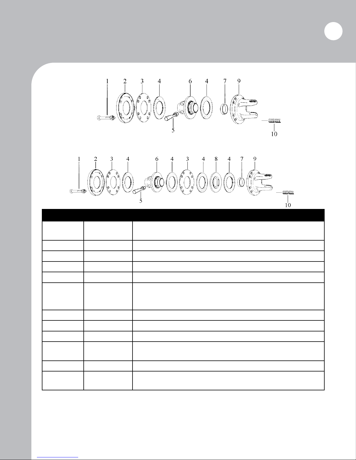
2-Disc Slip Clutch (460, 472)
4-Disc Slip Clutch (484)
37
Ref. No. Part No. Description
1 4-074
4-075
Not pictured 4-090 Nut for spring bolt
2 4-076 Backing plate
3 4-078 Spacer
4 T5-W20 Clutch lining
5 4-081
TC-330
4-082
6 4-084
7 4-085 Bushing
8 4-086
9 4-087
4-088
10 4-089 Spring
Not pictured 4-091-20
4-092
460, 472: Bolt
484: Bolt
Bolt with washer & lock nut (2 req.)
460, 472: Tapered bolt with nut (1. req.)
484: Tapered bolt with nut (1 req.)
484: Hub (1-3/4” x 20 spline)
484: Hex plate
460, 472: Rear ange yoke
484: Rear ange yoke
460, 472: Complete slip clutch assembly
484: Complete slip clutch assembly
Ordering replacement parts
Please contact the nearest Brown dealer for replacement parts. They will be able to meet most of your
equipment needs.
Page 38

M-400 Series B
Version 2.1.2
August 2008
 Loading...