

Page 1
BROUWER
SOD
Model: 4132506. New Holland
OPERATOR’S MANUAL
23324 Woodbine Avenue, Keswick Ontario Canada L4P 3E9
Tel (905) 476-6222 Fax (905) 476-6744 Web Site www.brouwerturf.com
HARVESTER
Brouwer Turf
KM99173
April 2017
Revision D
Page 2

Page 3

Turf Harvester
Operator’s Manual
Contents
Foreword
Section 1. Safety
Section 2. Controls
Section 3. Operation
Section 4. Maintenance/ Lubrication
Section 5. Adjustments
Section 6. Auto-Steer
Page 4

Page 5
Turf Harvester
Safety Precautions
IMPORTANT
The Owner and Operator, must assume responsibility for the safe operation of the machine, their own
safety, and the safety of others, by reading, understanding, an
and operating procedures as outlined in the machines Operator’s Manual.
Failure of the Owner or Operator to adhere to the recommended safety instructions and operating
proced
resulting in personal injury or property damage.
ures, indemnifies Brouwer Turf Equipment Inc. against any claims that may arise, due to accidents
It is not possible to list all situations that may affect the safety of the machine or the operator, and therefore
Brouwer cannot list all precautions, and identify all potential hazards, that may prevent accidents.
IF YOU DO NOT UNDERSTAND….ASK
BE A QUALIFIED OPERATOR BY ;
• Rea
• Re
• Askin
• Explaining th
WARNING
The Brouwer Roboma
purpose other than that for which they are designed.
Prior to being shipped from the manufacturer the machines are in
and warning/safety/operating decals are correctly positioned and secure
Before operating the machine the operator must check that all of the above items are
The machine must not be used if any guards, shields or warning/operating decals are damaged or missing..
Your new Robomax Turf Harvester has been designed and built to give many years of o
The service and reliability you receive from this product will be affected by the proper maintenance and operation
of the machine.
Use only genuine Brouwer replacement parts. Parts n
specifications or standards of manufacture and may void warra
component failure and possibly cause in an accident to the operator or others.
IMPORTANT
MODEL NUMBER
The Model Number appears on sales literature
Technical manuals and price lists.
SERIAL NUMBER
The serial number applies only to the machine
to which it is allocated.
The serial number MU
parts or calling for service
ding and obeying the instructions in this manual, the tractor manufacturers operator’s manual, and
the safety decals on the machine.
ceiving operational training on the sod harvester.
g your supervisor or equipment dealer to explain anything you do not understand.
e written instructions in the operator’s manual and safety decals to user/operators who
cannot read or understand them.
x Turf Harvesters are designed for safe efficient operation and must not be used for any
ot supplied by Brouwer may not meet Brouwer
ST be quoted when ordering
or warranty
d following, all of the safety instructions
spected to insure that all safety guards, shields
correctly located.
utstanding performance.
nty. The use of non-approved parts may result in
Page 6

Page 7

SAFETY
SECTION 1
Safety Symbols 1-1
Safe Operation 1-2
General Operating Safety 1-3/1-4
Maintenance Safety 1-4/1-6
Transport and Storage 1-7
Safe Service Procedure 1-7
Tire Service 1-7
Handling Chemicals 1-7
Safe Welding 1-8
Safety Warning Decals 1-9/1-11
Page 8

Page 9
WARNING
Unauthorized modifications may result in extreme
safety hazards to operato
could result in damage to the machine.
Brouwer Turf Ltd. Warns against and strongly rejects
and di
sclaims against any modifications, add-on
accessories or product modifications that are not
designed, developed, tested and approved by
Brouwer Engineering Department.
Any Brouwer product that is altered or modified in
anyway that is not autho
manufacture, including after market accessories or
component parts that are not approved by Brouwer
Turf Ltd. will result in the machines warranty being
voided.
All liability for personal injury and/or property damage
sed by any unauthorized modifications, add-on
cau
accessories or products not approved by Brouwer
Ltd. will be considered the responsibility of the
individual(s) or Company designing and/or making
such changes.
Brouwer Turf Ltd. will vigorously pursue full
indemnifi
for unauthorized post manufacture modifications
and/or accessories, should personal injury and/or
property damage result from any of the above.
cation and costs, from any party responsible
DANGER
TO PREVENT POSSIBLE SERIOUS INJURY OR
DEATH :
Under no circumstances is any service or maintenanc
e work to be performed on the machine
until :
• THE ENGI
• THE IGNITION KEY IS REMOVED.
• THE CAB
NE IS SWITCHED OFF.
DOOR IS LOCKED.
rs and bystanders, and
rized, after original
This Symbol means :
• ATTE
• BECOME ALERT !
Your safety and that of others is involved.
Signal word definitions.
The signal words below are used to identify levels of
‘hazard’
manual and on the safety decals that are placed on
the machine.
For your safety and that of others, read and follow the
informatio
words and/or the symbol shown above.
seriousness. These words appear in this
n and instructions given with these signal
SAFETY
NTION !
DANGER:
Indicates an imminently hazardous situation which if
not avoided WILL result in death or serious injury.
WARNING:
Indicates a potentially hazardous situation which if not
avoided COULD result in death or serious injury.
CAUTION:
Indicates a potentially hazardous situation which if not
avoided MAY result in minor or moderate injury.
It may also be used to alert against unsafe practices
or property damage.
CAUTION:
Used without the safety alert symbol indicates a
potentially hazardous situation which if not avoided
MAY result in property damage.
1-01
Page 10

Safe Operation
Operator preparation and Training.
Read the RoboMax Operation and Safety Manual, and
also the tractor operating manual. They must be kept on
the machine at all times.
• If an operator or mechanic cannot read and
understand English, it is the owners responsibility to explain the material contents to them.
• If any of the information or instructions in this
manual are not clear, contact your dealer or the
factory representative for clarification.
• Become familiar with the safe operation of the
machine, the operating controls and the safety
decals. If there are any questions concerning
safety, do not operate the machine until they are
clarified.
All safety guards and shields must be kept in
place and in good condition. All interlock switches
must be correctly adjusted.
• It is the owners responsibility to ensure that all
operators and service personnel are trained in
the proper operation and service procedures of
the machine.
• Wear appropriate work clothing, safety equipment
and work boots. Do not operate the machine with
loose clothing, long hair, or any jewelry, that may
get tangled in moving parts.
CAUTION
Wear suitable hearing protection such as
earmuffs or earplugs, to protect against hearing
impairment or hearing loss.
Operating equipment safely requires the full
attention of the operator. Do not wear radio or
music headphones while operating the machine.
• Never allow children or untrained persons to
operate this equipment. Local regulations may
restrict the age of the operator.
• Only the operator must be on the machine, never
allow riders on the machine. Riders can be
injured by foreign objects or can be thrown off the
machine. Also they may obstruct the ability of the
operator or the operators view resulting in unsafe
operation of the machine.
1-02
SAFETY
• The warning/safety decals must be kept clean,
legible, and undamaged. Do not operate the
machine if any decals are missing or damaged.
Obtain new decals from the factory.
• Do not operate the machine if drugs, alcohol or
medication are being used that can affect the
alertness or co-ordination of the operator.
Seek professional advice, before operating the
machine, if there is any doubt about the side
affects of any medication being taken that may
put your safety and that of others at risk.
• Keep animals and bystanders clear of the
machine, at a safe distance, when operating the
machine.
• The owner/operator is responsible for accidents
and/or injuries that may occur to themselves,
bystanders, or property that may occur as a result
of the operation of this machine.
Machine preparation
• Check the ‘operator presence’ interlock is
operating. Check tractor brake operation. Repair
or adjust any problem before operating the
machine.
• Do not tamper with or defeat safety devices.
Keep guards, shields and interlock safety devices
in place and in proper working condition. They
are for your protection.
• Check regularly that all fasteners, that is, nuts/
bolts, and retainer pins are secure.
• Check daily that the machine is in good working
condition. Check all tires for damage or excessive
wear.
• Use only accessories, attachments and
replacement parts that are approved by the
manufacturer.
WARNING
To prevent unauthorized persons having access
to the cab:
The cab door must be kept locked when in
service, and the key in possession of the
service person.
IF YO U DO NOT UNDERSTAND….ASK
Page 11
General Operating Safety
• Ensure all persons are clear of the machine
before starting the tractor engine. Keep hands
and feet clear of the cutting unit and all moving
parts.
• Do not ma
reversing and maneuvering. Look behind the
machine and downward when reversing.
• Keep all pe
operating area and pallet cavity, it may move
suddenly and result in serious injury.
• Use co
recommended in this manual.
• Exerci
roadways.
• Put the transmissi
the Parking Brake before dismounting. Leaving
the transmission in gear with the engine stopped
will not prevent the tractor from moving.
CAUTION
NEVER attempt to get on or off the machine
when it is moving.
Before leaving the operating position, place
the transmission in NEUTRAL, set the ‘park
ke’, lower the cutting heads and forks to
bra
the ground, stop the engine and remove the
ignition key.
Starting th
WARNING
To avoid possible injury or death from a
runaway machine, DO NO
by shorting across the battery terminals.
The machine can start when in gear if the
normal safety circuitry is bypassed.
• Start only in accord
this manual and also the tractor operators
manual.
• DO N
• Never
only from the operator’s seat, with the
transmission in NEUTRAL and park brake ‘ON’.
ke sharp turns. Exercise care when
rsons clear of the Robotic Arm
unterweights or wheel weights only as
se caution when approaching or crossing
on in NEUTRAL and apply
e Tractor
T start the engine
ance with the instructions in
OT use starting-aid fluid.
start the engine from the ground. Start
SAFETY
Transporting
• Exerci
• Ensu
Operating
• Do not chan
or over-speed the engine.
WARNING
• Inspe
• Operate with
Highway Operation
• To prevent collisions with other vehicl
• Slow do
• Use hea
• Couple brake pedals together for road travel.
To prevent Tipping
• Avoid holes,
1-03
se caution when loading or unloading the
machine on or off a truck or trailer.
re that the machine is properly ‘blocked
and secured during transport.
ge the engine governor setting,
Work in a ventilated area, never operate
the engine without adequate exhaust
ventilation.
Never run the engine in an enclosed area.
Exhaust fume
can be fatal if inhaled.
ct the area to harvested and remove any
objects that may be hazardous or may cause an
injury.
and other hazards.
moving tractors with attachments, towed equipment or self-propelled machines, frequently
check for traffic from the rear, particularly when
making turns, use turn signal lights.
wn and exercise caution when making
turns and crossing roads and railway tracks.
dlights, flashing warning lights and turn
signals day and night. Follow local regulations
for equipment lighting and marking.
Ensure that all lighting, signals and markings
are visibl
Repair or replace any lights, signals or marking
that is damag
may cause instability and the machine to tip.
e, clean and in good working order.
s contain carbon monoxide and
adequate light and avoid any holes
es, slow
ed or is missing.
ditches, slopes, and obstacles that
Page 12

SAFETY
WARNING
Never drive close to the edge of a gully or
steep embankment that may collapse and
cave-in, causing the machine to tip.
• Shift to a LOW gear before descending a
steep hill, to assist in braking and improving
your control of the machine.
Use engine braking to reduce speed before
applying the tractor brakes.
• Never coast down a hill, run-away machines
are liable to tip.
• Slow down and exercise caution when making
turns and changing direction on a slope.
Stopping Operation
• Before stopping the engine: Reduce the
engine speed to ‘SLOW’ and let it operate at
‘no load’ for five to ten minutes, to allow the
engine to cool down.
To safely park the machine:
• Stop it on level ground, move all controls to
the ‘OFF’ position. Lower the Cutter Head and
Forks to the ground. Put the transmission in
NEUTRAL, apply the brakes and stop the
engine. Before leaving the operator’s seat,
wait for the engine and moving/rotating parts
to stop. Remove the ignition key.
To free a ‘mired’ machine.
• Check that all towing devices are of adequate
size/strength to handle the load.
• Always attach to the Draw Bar of the towing
unit. Do not use the front attachment point.
Apply power smoothly to take up slack, a
sudden pull could ‘snap’ the towing device
causing it to ‘whip’ or ‘recoil’ dangerously.
Caution should be exercised when attempting to
free a machine that is stuck in mud. Hazards that can
occur when towing, and are to be avoided are:
• The towing tractor overturning.
• The tow chain failing and recoiling. (Use of a
cable is not recommended).
• Tow-bar failing.
• The harvester becoming unstable and tipping.
1-04
The following procedures are recommended;
• If possible reverse the machine out, if it is
‘mired’ in mud.
• Dig mud out from behind the wheels. Place
boards behind/under the wheels and reverse
out ‘slowly’. Keep bystanders clear of the
rear of the machine
• Dig mud out from in front of the wheels and
drive ahead ‘slowly’.
Maintenance Safety
WARNING
Do not service or repair this machine with
the attachments in the raised position, unless
they are securely blocked, or the safety
devices are engaged.
Failure to do so could result in serious injury
or death.
Do not enter the Forks/Piling Ca vit y area
when the engine is running.
• To attain maximum saf et y and the optimum
harvesting results, maintain your RoboMax
Harvester according to the recommended
schedules and instructions in this manual.
• When servicing or operating the machine do
not wear loose clothing or jewelry that can
entangle in machinery and cause personal
injury.
• Never allow untrained persons to operate or
service the machine.
• Allow the engine and rotating/moving parts to
come to a complete stop before attempting
any service or repair work.
• Disconnect the battery cables before making
any repairs, and before doing any welding on
the machine. Disconnect ‘negative’ first, then
‘positive’. Reconnect in the reverse order.
• Carefully release pressure from components
with ‘stored’ energy.
• Park the machine on smooth, firm, level
ground.
• Replace worn, damaged, or faulty parts with
parts supplied by the manufacturer.
• Before working on the machine, lower the
utter Head and Forks to the ground. If the
C
machine needs to be raised, use jack stands.
If left in a raised position hydraulic supports
n settle or ‘leak’ down.
ca
Page 13

Maintenance Safety
WARNING
Do not support the machine on cinder blocks,
hollow tiles, or props that may crumble under
continuous load.
Do not work under a machine that is supported
solely by a jack.
• To red
• Clea
Handling Fuel
WARNING
• Exerci
Do not over-Fill. Fuels are flammable and
vapors are explosive. Avoid spilla
cans use only approved containers and
a funnel. Clean-up spills immediately.
• Do not smoke or allo
or cause sparks near the fuel.
Never drain or fill the fuel tank indoors.
• Never
fuel when the engine is running or if it is hot.
• Never h
an open flame or any device that may create
sparks and ignite the fuel or vapors.
• Ensu
and the containers, are replaced tight
and secure.
uce fire hazards: Keep the engine,
muffler, battery compartment and fuel storage
area free of grass, leaves, debris or grease
build-up.
n
-up any fuel or oil spillage.
se caution when refueling
w naked flame
remove the Fuel Tank Cap or add
andle or store fuel containers near
re that the Closure Caps on the Fuel Tank,
WARNING
To prevent sparks from static discharge:
• Do not fill containers in a vehicl
truck, or a trailer bed that has a plastic liner.
Fill the containers on the ground, away from
the vehicle.
• Always keep
with the rim of the fuel tank, or container
opening, until fueling is completed.
• Do not u
• Always be p
aid kit and fire extinguisher close to hand.
• Keep eme
ambulance services, and doctors close to your
telephone.
the fuel dispenser nozzle in contact
se a nozzle lock-open device.
repared in case of fire. Keep a first-
rgency numbers for fire, hospital,
ge. If using fuel
e, on a
SAFETY
Hydraulic System
WARNING
The RoboMax Hydraulic System operates under
high pressure.
To prevent serious injury from hot, high pressure oil:
• Nev
Use cardboard, paper or wood.
• High p
• Relieve hig
• Fully tighten fittings and
• Lower Cutter
• Visually ch
• Repl
• Thoroug
IMPORTANT
To prevent serious damage to the hydraulic
system components, do not allow any contaminants to
enter the hyd
fittings and areas to be worked on. Cap and plug any
connections that are disconnected.
• Before disconnecting, tag or mark the location of
• Che
• Align the hoses with
• Kinked o
1-05
er check for leaks with bare hands.
ressure oil can penetrate the skin. If it is
injected into the skin it must be surgically
removed within a few hours, by a doctor familiar
with this type of injury. Failure to do so may
result in gangrene.
h pressure before disconnecting
hydraulic lines or fittings.
connections before
pressurizing the system.
Head and Forks to the ground,
disengage all drives, apply the park brake, stop
the engine and remove the ignition key, before
inspecting or disconnecting hydraulic lines or
fittings.
eck daily all hydraulic hoses, tubes
and fittings for leaks. Replace any worn or
damaged hoses, tubes or fittings before
operating the machine.
acement hoses or tubes must be routed in
the same location and path. Do not move
clamps, brackets or ties to new locations.
hly inspect all hoses, tubes and fittings
every 300 hours.
raulic system. Clean thoroughly around all
the connection.
ck that ‘O-Rings’ are clean and hose fittings
are properly seated before tightening.
out twisting. Twisted hoses
can cause couplings to loosen as the hose
flexes during operation, resulting in oil leaks.
r twisted hoses can restrict the oil flow
causing the system to malfunction, the oil to
overheat and possible hose failure.
Page 14

SAFETY
Cooling System
WARNING
To prevent serious injury from hot coolant
and steam, DO NOT rem
cap when the engine is running and/or hot.
Allow the engine and system to cool, and
use caution when removing the radiator cap.
• Do not op
mended coolant mixture.
• Add top-u
NOT
directly to the radiator
• Ensu
secure.
• If the radiator cap mu
engine and allow the cooling system to cool,
until the cap is cool to the touch. Loosen it
slowly to relieve pressure, before removing
completely.
Battery Service
WARNING
The sulfuric acid in the battery electrolyte is
poisonous. It can cause serious skin burns
and blindness if splashed in the eyes.
CAUTION
Always wear protective glasses/goggles,
and protective clothing and use insulated
tools when working with batteries.
Read, understand, and obey all battery manuf acturers instructions and warnings.
Battery posts, terminals and relate accessories
contain lead, lead compounds and chemicals,
wash your hands after handling them.
Avoid Hazards By:
• Fill/top-up b
• Wea
• Avoid breathi
• Avoid spilling,
electrolyte.
• Follow proper ‘jump-start’ procedure.
If acid is splashed on your person:
• Flush the affe
• Apply bakin
the acid.
• Flush you
minutes. Get medical help immediately.
1-06
erate the engine without the recomp coolant into the recovery tank
re that the radiator cap is tight and
atteries in a well ventilated area.
ring eye protection and rubber gloves.
ng fumes.
splashing or dripping
cted skin with water.
g soda, or lime, to help neutralize
r eyes with water for 15 to 30
ove the radiator
st be removed, stop the
If acid is swallowed:
• Do not ind
• Drin
not exceed 2 liters (2 Quarts).
• Get medi
Battery Charging
• Cha
area, away from sparks or open flame.
• Unpl
disconnecting the battery.
Jump Starting
• Che
condition.
• Turn the ig
‘OFF’, on both machines.
• Position the
battery close to, but not touching, the
machine with the dead battery, to ensure that
the cables will easily reach.
Connecting the Cables
• Do not allo
metal parts except those intended.
• N
ever connect the positive ‘+’ (red) terminal
to the negative ‘-‘ (black) terminal.
• Ensu
moving engine parts when starting.
• Con
cable to the positive ‘-‘ terminal on one
battery. Connect the other end to the
positive ‘+’ terminal on the other battery
• Con
cable to the negative ‘-‘ terminal on the
‘charged’ battery. Connect the other end of
the cable to the engine block on the
machine with the ‘dead’ battery.
• Start the machine that ha
battery, then start the machine that has the
‘dead’ battery.
• Remove the j
reverse order of connecting. Do not allow the
cable clamps to touch any metal parts while
the other end is connected to a battery
terminal.
IMPORTANT
Keep the battery terminals clean. Smear them
with white grease to prevent corrosion.
The positive terminal (red) protective cover must
be ke
uce vomiting
k large quantities of water or milk, but do
cal help immediately.
rge batteries in an open well ventilated
ug the charger before connecting or
ck that the Jumper cables are in good
nition and all electrical accessories
machine with the ‘charged’
w the cable clamps to touch any
re that the cables cannot get caught in
nect one end of the positive ‘+’ (red)
nect one end of the negative ‘-‘ (black)
umper cables in the exact
pt in place.
s the ‘charged’
Page 15

Transporting and Storage
• If the machin
cannot be moved under its own power, it
should not be towed, as it would be extremely
difficult to steer and stop it.
• It is recom
flat-bed carrier or a truck/trailer. Use chains to
secure the machine on the carrier.
Storage
IMPORTANT
If the Harvester is to be stored ‘inside’ keep the
doors op
procedure below is complete.
• Stop the engi
• Drai
• Disco
• Keep the Ha
• Do not sto
such as a water heater with a pilot light.
Safe Service Procedures
• Do not service the harve
• Whe
• Tighten the wheel lug n
• Refit all safet
Tire Service
WARNING
Do not operate the harvester if any of the tires are
badly wo
The left rear
Calcium Chloride solution and is extremely heavy
(934 lb). Exercise caution when removing or
replacing it. Use suitable tools and equipment and
hoist equipment with adequate lift capacity.
It is recommended that only experienced and
qualified pe
n the fuel tank into an approved container
and shut off the fuel. Store the fuel in a cool dry
location.
nnect the battery cables.
locked, secure storage place, to prevent
tampering, and children from playing in the
area.
close to heating appliances with an open flame,
or the engine is running.
n servicing a four wheel drive machine,
when necessary raise front and rear wheels
off the ground. This is to prevent the machine
being pulled of the jack stands if power is
applied to the wheels.
as specified in the maintenance section.
have been removed during service.
rn or damaged.
e should become disabled, and
mended that it be transported on a
en to ensure good ventilation until the
ne and allow it to fully cool down.
rvester and fuel containers in a
re the Harvester of fuel containers
ster when it is moving
uts to the correct torque
y guards and shields that may
wheel/tire assembly is loaded with a
rsonnel dismantle wheel assemblies.
SAFETY
CAUTION
Operating the machine with loose wheel lug nuts
sult in damage to, and require the replace-
will re
ment of, wheel assembly components.
• Always
not inflate tires above the recommended operating pressure shown on the side wall.
WARNING
Never weld or heat a wheel/tire assembly. The heat
cause increased air pressure and result in the
can
tire exploding. Explosive separation of tire and rim
components can result in serious injury or death
• Whe
air hose that is long enough to allow you to
stand to one side of the wheel, not in front or
over it. Use a safety cage if one is available.
Handling Chemical Products
CAUTION
To prevent serious personal injury avoid direct
exposure to h
hazardous chemicals include : fuels, lubricants,
coolants, paints and adhesives.
Material Safety Data Sheets (MSDS)
Material Safety Data Sheets provide specific details on
cal products that affect:
chemi
• Physical a
• Safety proce
• Emerge
It is recommended that the MSDS data is checked
before a jo
chemical. This informs of the possible risks and the
safest way to proceed. Follow carefully the recommendations.
Proper Waste Disposal
• Improp
• Use lea
• Do not po
• Air con
maintain the correct tire pressures. Do
n inflating tires use a clip-on chuck, and a
azardous chemicals. Potential
nd personal health hazards.
dures.
ncy response techniques.
b is started that involves a hazardous
er disposal of waste material is harmful
to the environment. Some potentially harmful
products used on machines are: oil, fuel, filters
coolant, brake fluid, and batteries.
k proof containers when draining fluids.
Do not use food or beverage containers that
someone may mistakenly drink from.
ur waste fluids onto the ground,
down a drain or into any natural water source.
ditioning refrigerants are harmful to the
atmosphere. Government regulations may
require a certified technician to service and
properly recover and recycle refrigerants.
1-07
Page 16
SAFETY
• Before disposing of waste material, enquire at your local environmental or recycling facility
for instructions on proper waste disposal.
Welding on Painted Areas
CAUTION
Hazardous fumes are generated when paint is h
The use an approved respirator is recommended when welding, sanding or grinding on painted
areas, to avoid the inhalation of fumes or dust.
• It is recom
the area to be affected by heating.
• If solvent or strippe
Remove any stripper or solvent contain
Allow a minimum of 15 minutes for fumes to disperse before welding.
• Do not use chlorinated sol
that is well ventilated to allow fumes and/or dust to disperse.
CAUTION
Do not weld, solder or use a torch close to pressu
Flammable spray can be generated by burst fluid lines resulting in severe burn injury to
yourself and bystanders.
mended that paint be removed a minimum of 4 inches (100mm) from around
r is used, wash them off with soapy water before doing any welding.
vent in areas where welding will be done. Do all work in an area
eated when welding, soldering, or using a torch.
ers and other flammable material from the area.
rized fluid lines, that may cause them to burst.
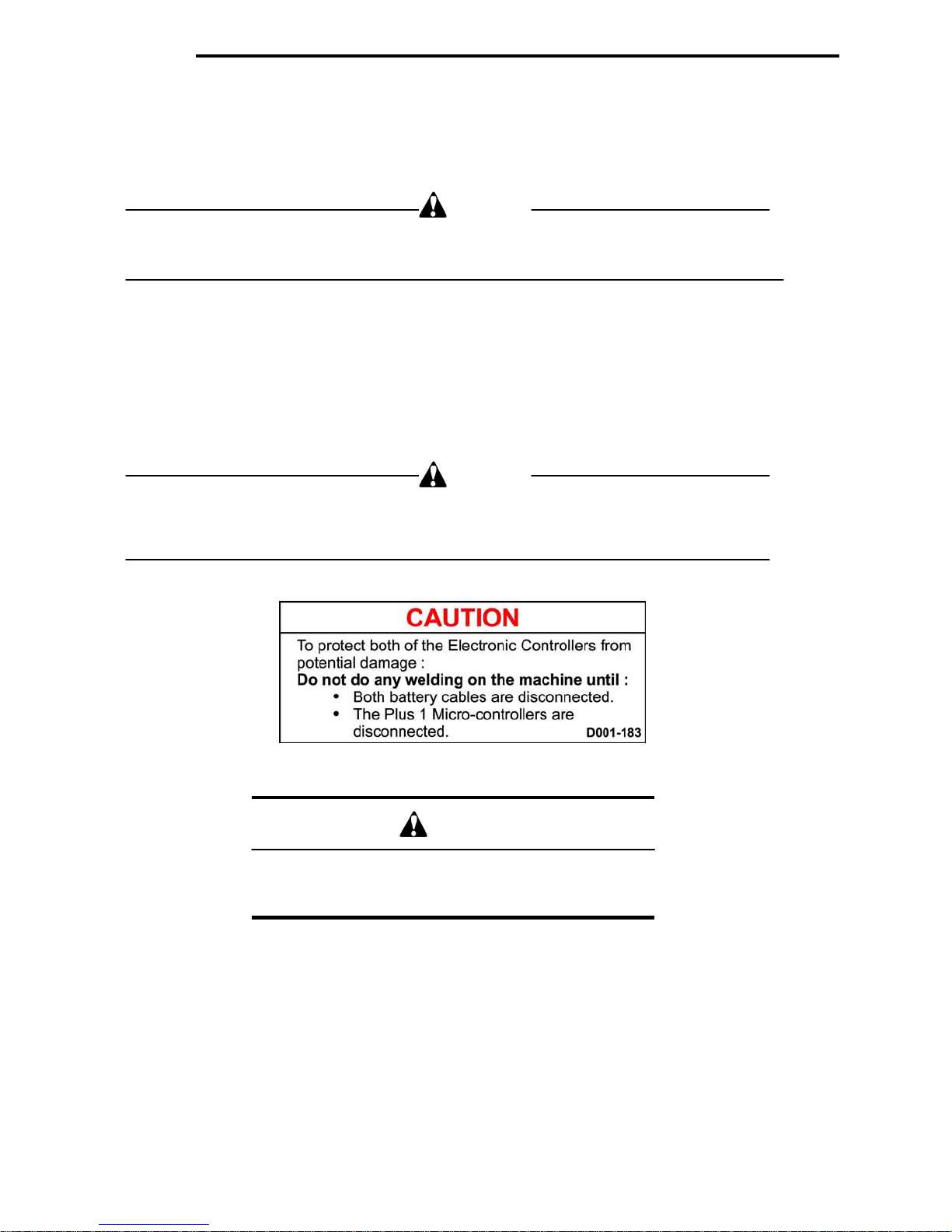
CAUTION
Exercise extreme caution when removing/installing
controller connections and verify proper locations.
1-08
Page 17
Page 18
Page 19
D001-222
Page 20

Page 21

CONTROLS
SECTION 2
Cab Controls 2-1
E-Stop 2-1
Auto-Steer Controls 2-1
Cutter Blade 2-1
Main Conveyor 2-1
LED. Counter 2-1
Depth of Cut 2-2
Main Conveyor Lift 2-2
Manual Over-Ride Controls 2-2
Control Panel and Screen 2-3
Initial Start 2-3
Stacking Pattern Selection 2-3
Inactive Stacking 2-4
Active Stacking 2-5
Step Sequence 2-5
Active Pallet – Full 2-6
Inactive Pallet – Full 2-7
Manual Mode 2-8
Pallet Dispenser 2-9
Page 22

Page 23
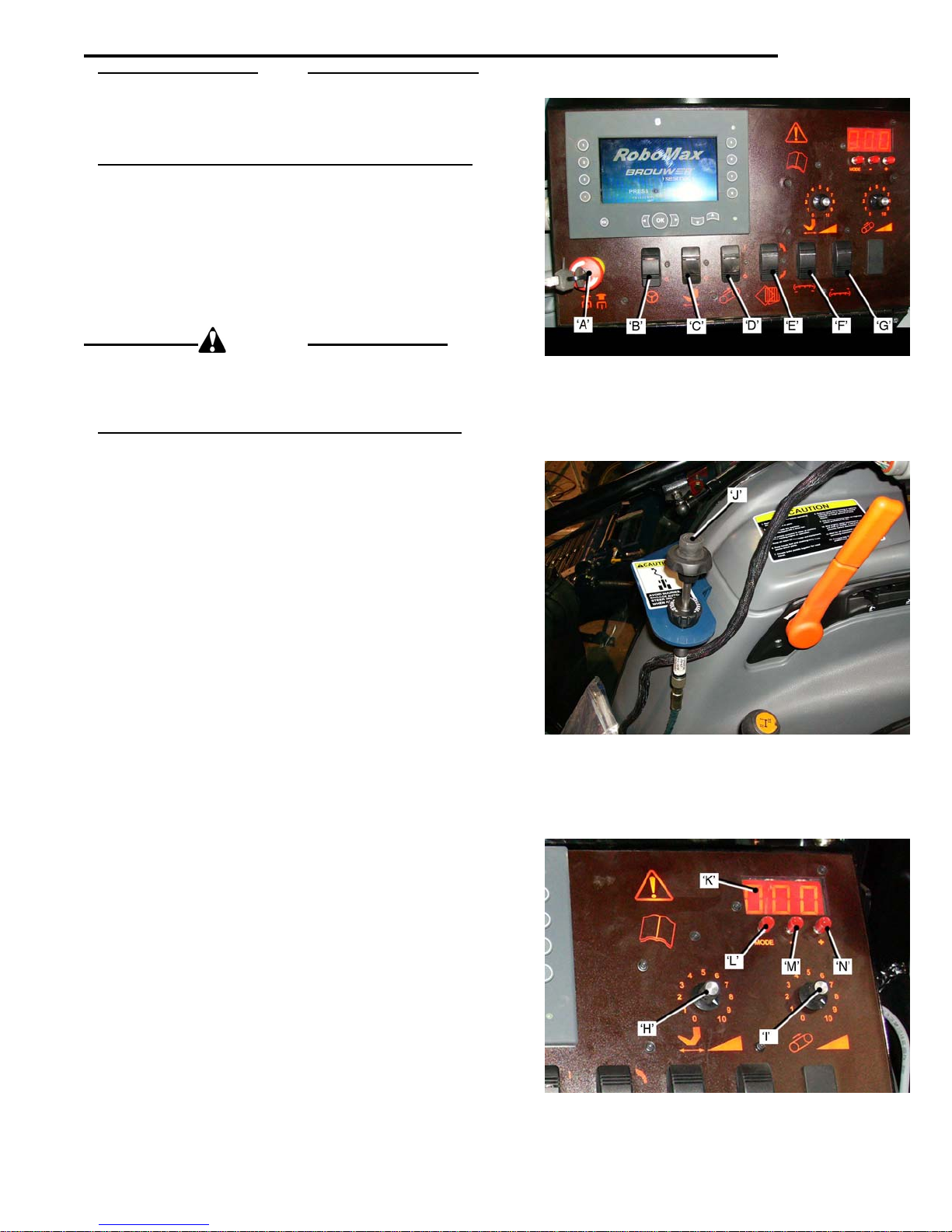
NOTE
All Harvester operating controls, except for De
Cut, Conveyor Lift, and Auto-Steer Fine Adjustment,
are on the Control Console at the right hand side of the
operator’s seat.
Harvester E-Stop Switch
The keyed E-Stop Switch ‘A’
enables all harvester functions except: Travel, Depth
of Cut, and Cutter Head position.
When the E-Stop Switch is pushed ‘IN’ harveste
functions are disabled, except: Travel, Depth of Cut and
Cutter Head position.
Turn the key to return to the switch to the ‘ON’ position.
WAR
To prevent possible injury, in an emergency, push the
E-Stop Switch ‘IN’ to stop all harve
travel.
Stop travel by ’de-clutching the transmission.
Auto-Steer Operation
The Auto-Steer is engaged, or disengaged, with the
cker Switch ‘B’.
Ro
Fine Adjust Control
The Fine Adjust Control ‘J’
strip. Turn the Control Knob ‘clockwise’ to reduce the
waste strip. Turn ‘counterclockwise’ to increase it.
Cutter Blade
The Cutter Blade is engaged or disengaged with the
cker Switch ‘C’.
Ro
Adjust the Cutter Blade speed with Control Knob ‘H’.
Rotate the control ‘clock
speed. Rotate it ‘counterclockwise to ‘reduce’ the
blade speed.
Main Conveyor
The Main Conveyor drive is engaged or disengaged with
cker Switch ‘D’.
Ro
The Conveyor speed is controlled with Control Knob ‘I’.
Rotate the Control Knob ‘clock
speed’ Rotate it ‘counterclockwise’ to reduce speed.
Pallet Injector
To engage the Pallet Injector press Rocker Switch ‘E’
‘UP’, to disen
‘E’ ‘DOWN’.
To ‘DROP’ the Upper Pallet Injector Paddles press
Ro
cker Switch ‘F’ ‘DOWN’. To raise the Upper Pallet
Injector Paddles press Rocker Switch ‘F’ press ‘UP’.
To ‘DROP’ the Lower Pallet Injector Paddles press
Ro
cker Switch ‘G’ ‘DOWN’. To raise the Lower Pallet
Injector Paddles press Rocker Switch ‘G’ press ‘UP’.
LED Counter
The LED Counter ‘K’ displays the Main
one mode, and the ‘tooth count’ for the Sod Roll Flap
orientation in the other mode. The Control ‘L’ selects the
mode.
’ Control ‘N’ and the ‘-‘ Control ‘M’ adjusts the
The ‘+
tooth count. Increasing the tooth count, Control ‘N’,
moves the Roll Flap counterclockwise, (higher).
Decreasing the tooth count, Control ‘M’,
Flap clockwise, (lower), as viewed from the operator’s
position.
gage the Pallet Injector press Rocker Switch
in the ‘OUT’ position
NING
ster functions, except
, adjusts the width of the waste
wise’ to ‘increase’ the blade
wise to ‘increase’ the
Conveyor RPM in
moves the Roll
pth of
r
CONTROLS
2-01
Page 24
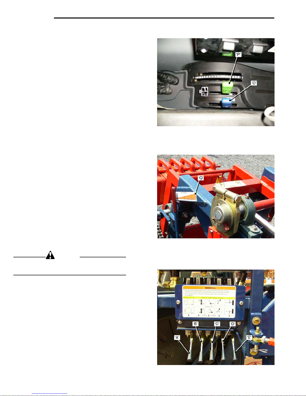
CONTROLS
Depth-of-Cut
The Depth of Cut Adjustment Lever ‘P’(green), is
located to the right of the operator’s seat.
‘Increase’ the depth-of-cu
‘Decrease’ th
A depth of cut indicator ‘Q’
a guide when making adjustments to the depth-of-cut.
Main Conveyor Lift Lever
The Main Conveyor Lift Lever ‘O’ (blue), is
the right of the operator’s seat.
wer’ the Main Conveyor and Cutter Head, push
To ‘lo
the lever ‘forw
To ‘raise’ the Main Convey
the lever ‘rear
Manual Over-Ride Controls
CAUTION
Do not operate the Manual Over-Ride Controls when
the Harvester Switch is ‘ON’
These controls allow manual control of:
Robotic Arm, Gripper Head, and Indexing Conveyor
(bad roll ejection).
The engine must be running and the Harvester Switch
in the ‘OFF’ position, (Ina
Lever ‘A’ controls
Lever ‘B’ controls
Lever ‘C’ controls
Lever ‘D’ controls
Lever ‘E’
2-02
e depth-of-cut: move the lever ‘forward’.
ard’.
ward’.
the Indexing Conveyor.
the Gripper Head ‘rotation’.
the Robotic Arm ‘reach’.
the Robotic Arm ‘lift’.
controls the Robotic arm ‘rotation’.
t: move the lever ‘rearward’.
, on the Cutter Head acts as
located to
or and Cutter Head, pull
ctive Screen).
Page 25
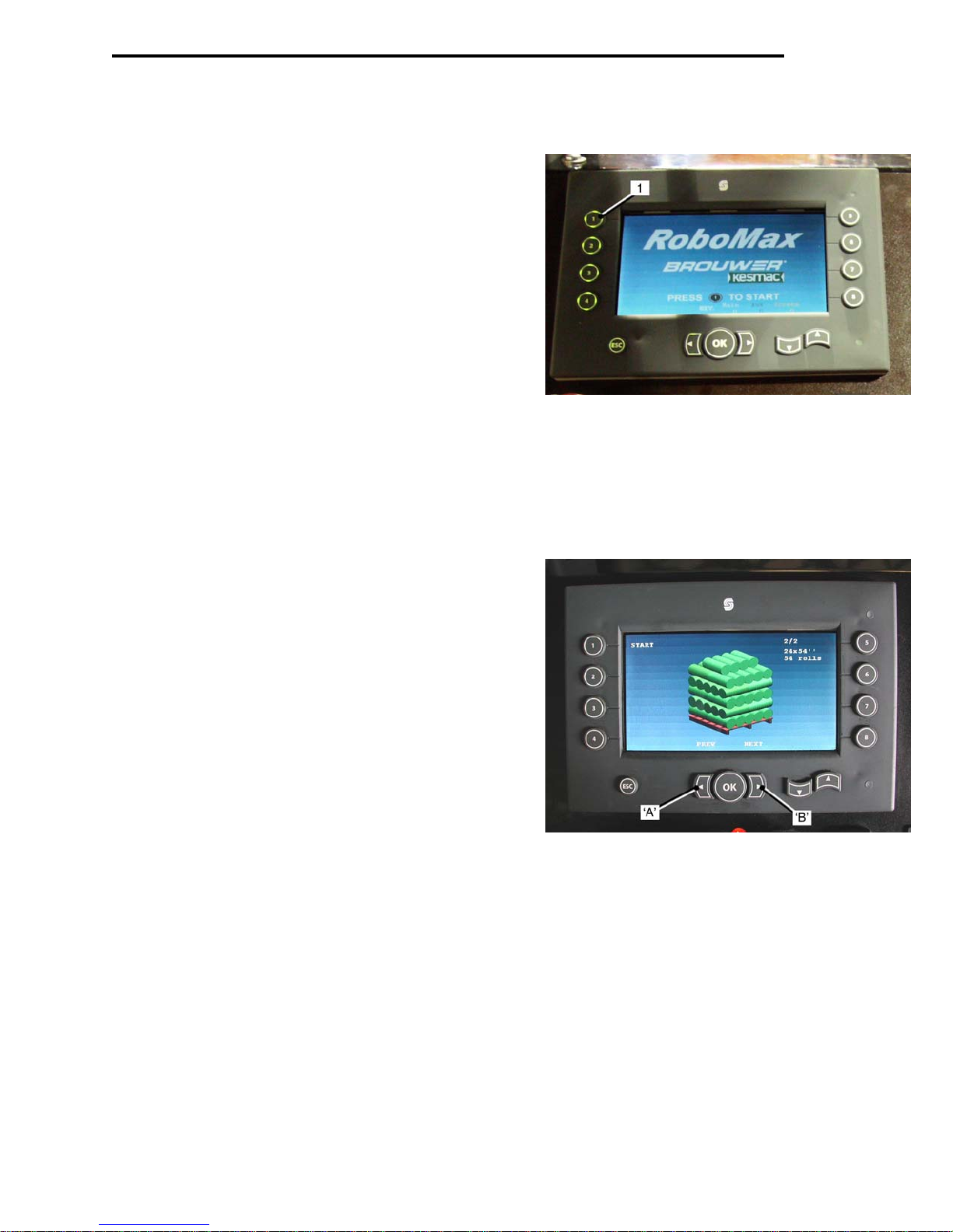
CONTROLS
Control Panel Screens
Initial Start Screen
The Initial Start Screen is displayed when the tractor
ignition key is switched to ‘ON’
• Press
the Stacking Pattern Selection Screen, after the
flashing red ‘WA
Stacking Pattern Selection Screen
The Stacking Pattern Selection Screen, allows the
operator to select the number of rolls on each pallet.
• Press the left arrowed pa
right arrowed pad ‘B’ (next), to togg
the selections.
• Press Pad ‘1’ (star
‘Inactiv
Pad ‘1’, to start the Controller and bring up
e Stacking Screen’.
.
IT’ in top left corner goes ‘out’.
d ‘A’ (prev), or the
le between
t), to bring up the
2-03
Page 26
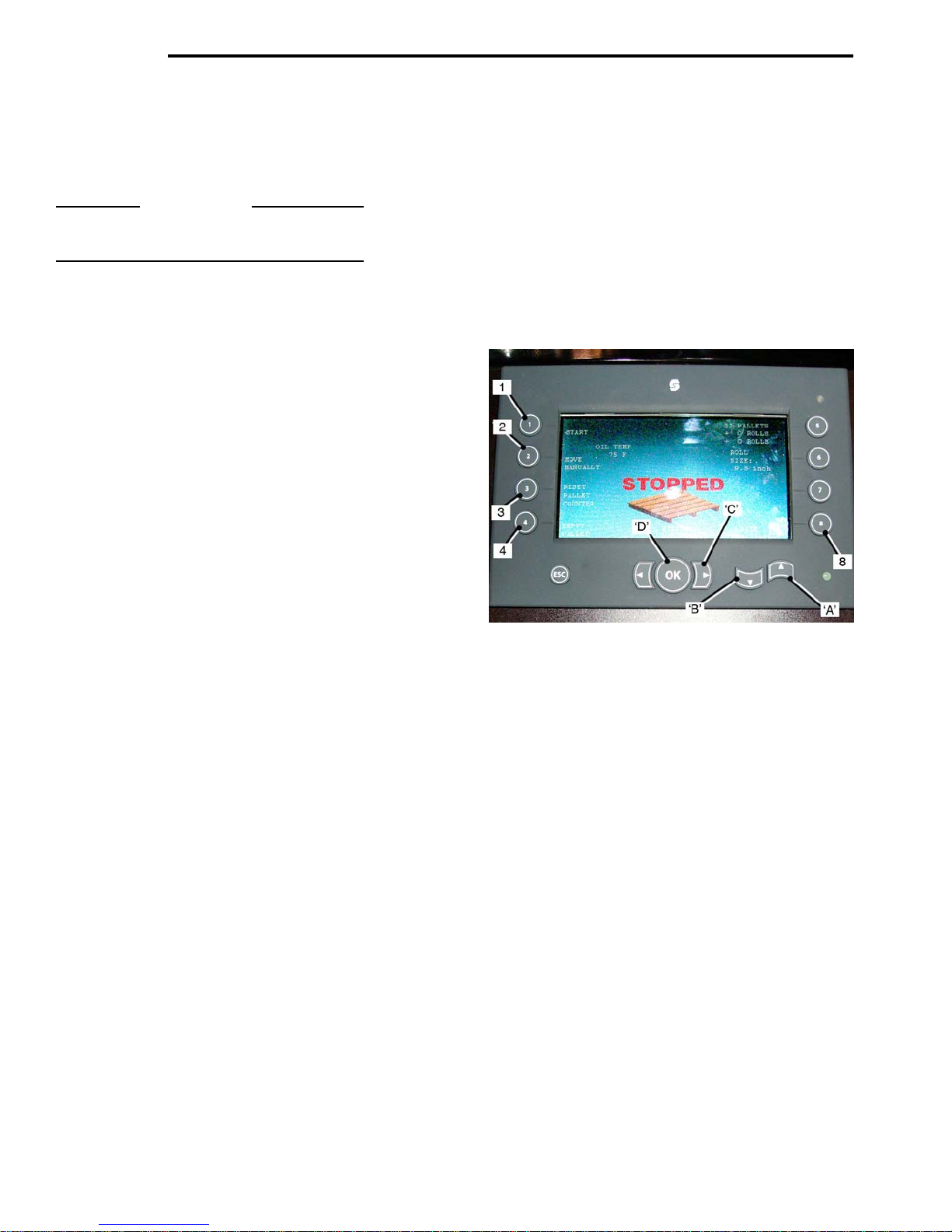
CONTROLS
Inactive Stacking Screen
The Inactive Stacking Screen is displayed during
Initial Start-up.
IMPORTANT
Do not pre
Active Stacking Screen is displayed.
The Inactive Stacking Screen will also be displayed
when the stacking sequence is stopped.
• Press Pad ‘1’, (start) to display the
Activ
• Press
the Mo
• Press, and h
(reset pallet counter) to reset the pal
to z
• Press
a ne
(The forks will not move in ‘Inactive Screen’).
• Press
Index Conv
• Press the ‘UP’ Arro
ease the sod roll diam
of 0.10 inch.
• Press the ‘DOWN’ Arro
decrease
of 0.10 inch.
• Press the ‘Ri
display the Calibration Screen.
• Press the ‘OK’ Pad ‘
the Step Sequenc
2-04
ss any control panel pads until the
e Stacking Screen.
Pad ‘2’ (move manually) to display
ve Manually Screen.
old for three seconds, Pad ‘3’
let counter
ero.
Pad ‘4’ (empty pallet) to indicate
w pallet. An ‘empty pallet’ will be display-
ed and the pallet roll quantity is reset to zero.
Pad ‘8’ (roll adv.) to advance the
eyor one position.
w Pad ‘A’ (add) to incr-
eter in increments
w Pad ‘B’ (sub.) to
the sod roll diameter in increments
ght Arrow’ Pad ‘C’ (calib.) to
D’ (step seq.) to display
e Screen.
Page 27
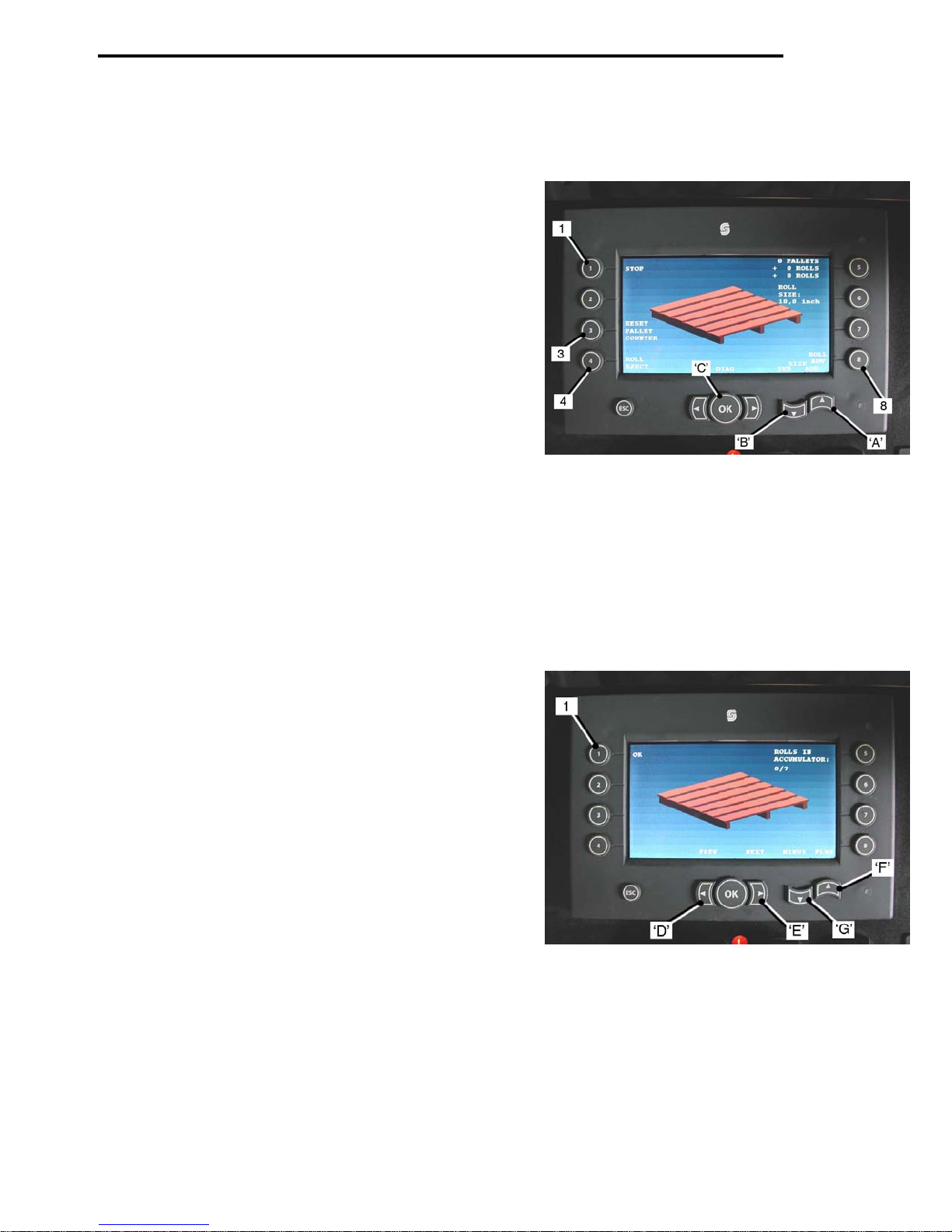
CONTROLS
Active Stacking screen
The Active Stacking Screen is displayed during the
stacking sequence.
• Press Pad ‘1’ (stop), to stop the stacking sequence, and display the Inactiv
Screen.
• Press an
pallet counter) to reset the
• Press
‘bad roll’
• Press
Index Conv
• Press
the sod roll diameter in increments of 0.10 inch.
• Press the ‘DOWN’ Arro
crease the sod roll dia
0.10 in
• Press the ‘OK’ Pad ‘
Diagnostic Screen.
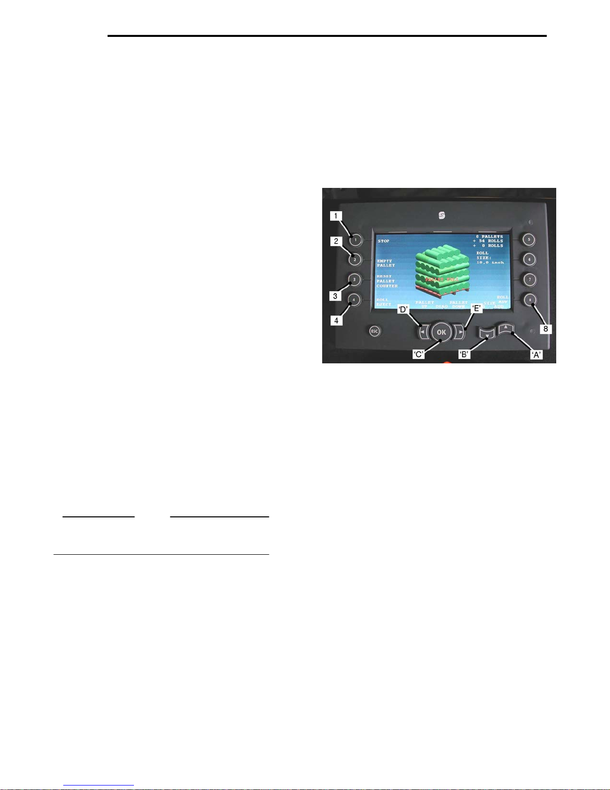
Step Sequence Screen
The Step Sequence Screen is displayed when the
Step Sequence Pad ‘
Screen is Pressed.
• Press
Inactiv
• Press the ‘Le
move five sod rolls from the pallet di
• Press the ‘Ri
add five sod rolls to the pallet dis
• Press the ‘UP’
sod rolls to the Index Conv
• Press the ‘DOWN’
subtrac
Count.
2-05
d hold, for three seconds, Pad ‘3’, (reset
counter to zero.
Pad ‘4’ (roll eject), to activate the
ejection.
Pad ‘8’ (roll adv.), to advance the
eyor one position.
the ‘UP’ Arrow Pad ‘A‘(add), to increase
w Pad ‘B’ (sub), to de-
meter in increments of
C’ (diag.), to display the
OK’, on the Inactive Stacking
Pad ‘1’ (OK), to return to the
e Stacking Screen.
ft Arrow Pad’ ‘D (prev.) to re-
ght Arrow Pad’ ‘E’ (next), to
Arrow Pad ‘F’ (plus) to add
eyor Count.
Arrow Pad ‘G’ (minus) to
t sod rolls from the Index Conveyor
e Stacking
splay.
play.
Page 28
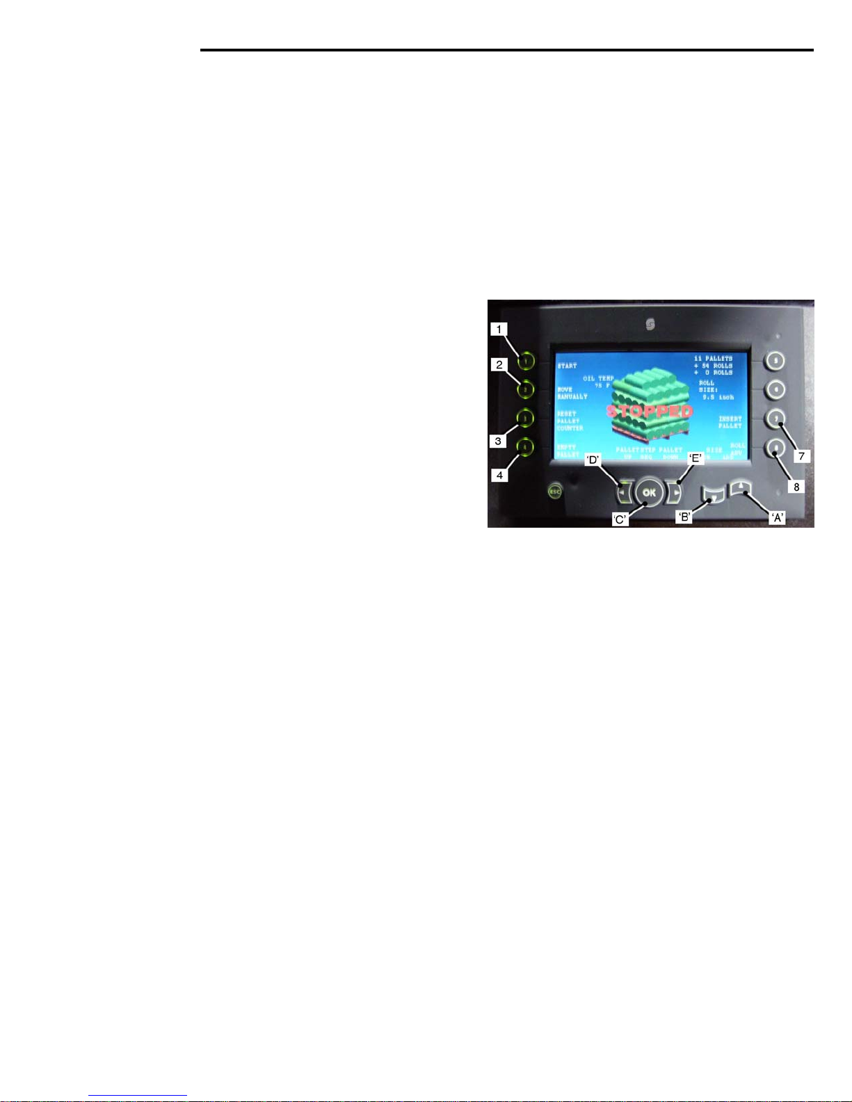
CONTROLS
Active Pallet Full Screen
The ‘Ac
when the pallet is full.
2-06
tive Pallet Full’ Screen is automatically displayed
• Press
Pallet Screen.
• Press
• Press, and h
• Press
ejection.
• Press
• Press the ‘UP’ Arro
the sod roll diameter in increments of 0.10 inch.
• Press the ‘DOWN’ Arro
• Press the ‘Left Arro
raise the pallet lift.
• Press the ‘Ri
to lo
NOTE
‘Insert Pallet’ appea
a full pallet is displayed.
Pad ‘1’ (Stop), to display the Inactive
Pad ‘2’ (Empty Pallet), to indicate a new
pallet. An empty pallet will be displayed and pallet
roll quantity is reset to zero.
the new pallet to the upper position.
old for three seconds, Pad ‘3 ’(Reset
Pallet Counter) to res
Pad ‘4’ (Roll Eject), to activate the ‘bad roll’
Pad ‘8’ (Roll Adv.), to advance the Index
Conveyor.
w Pad ‘A’ (Add), to increase
crease the sod roll diameter in incremen
of 0.10.
w’ Pad ‘D’ (Pallet Up), to
ght Arrow’ Pad ‘E’ (Pallet Down),
wer the pallet lift.
rs on the screen only when
The pallet lift raises
et the Pallet Counter to zero.
w Pad ‘B’ (Sub), to de-
ts
Page 29
CONTROLS
Inactive Pallet Full Screen
The Inactiv
the Pad ‘1’ (Stop) i
Screen.
• Press
Activ
• Press
the Mo
• Press Pad ‘3’ (Reset Pallet Counter), to
reset the pallet counter to zero.
• Press
a ne
and pallet roll quantity is reset to zero. The pallet
will not ‘raise’ until you go to ‘Active Screen’.
• Press
Conv
• Press
the sod roll diameter in increments of 0.10 inch.
• Press the ‘DOWN’ Arro
crease th
of 0.10 inch.
• Press the ‘OK’ Pad ‘C’ (Step Seq.) to
• Press the ‘Left Arro
raise the pallet lift.
• Press the ‘Ri
to lo
• Press
Pallet Dispens
e Pallet Full Screen is displayed when
s pressed on the Active ‘Pallet Full’
Pad ‘1’ (Start), to return to the
e Pallet Full Screen.
Pad ‘2’ (Move Manually), to display
ve Manually Screen.
Pad ‘4’ (Empty Pallet), to indicate
w pallet. An empty pallet will be displayed
Pad ‘8’ (.) to advance the Indexing
eyor one position.
the ‘UP’ Arrow Pad ‘A’, (Add), to increase
w Pad ‘B’ (Sub), to de-
e sod roll diameter in increments
the Step Seq
wer the pallet lift.
Pad ‘7’ (Insert Pallet), to initiate the
uence Screen.
w’ Pad ‘D’ (Pallet ‘Up’), to
ght Arrow’ Pad ‘E’ (Pallet ‘Down’)
e Sequence.
display
2-07
Page 30
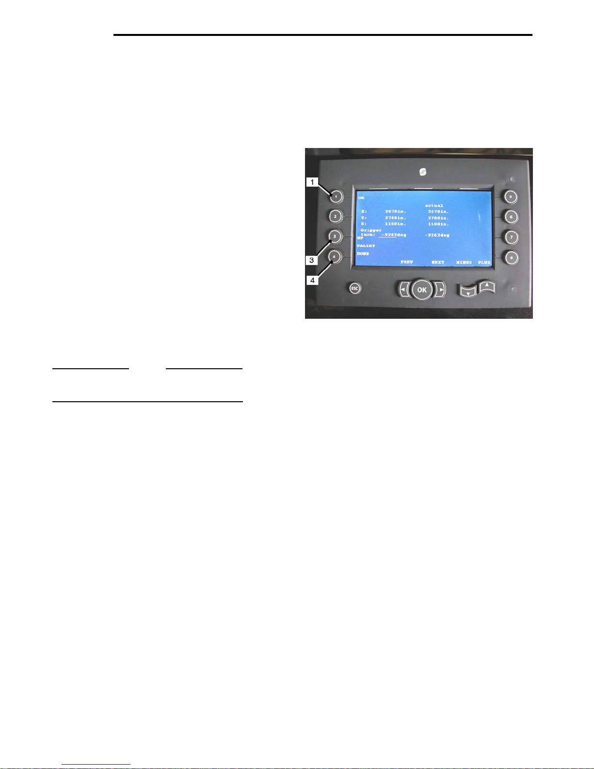
CONTROLS
Manual Mode Screen
When the Mo
system allows the operator to Operate the Robotic
Arm, and the Gripper Head, using the Control Levers
located at the left rear of the machine.
The Pallet Lift Forks ‘Lift’ and ‘Lower’ functions are
controlled from the Screen.
• Press
Inacti
Stacking Screen.
• Press
Forks.
• Press
Lift Forks.
NOTE
Refer to page 2-2 for the Manual Over-Ride
Control Levers Operation.
2-08
ve Manually Screen is selected, the
Pad ‘1’ (OK), to return to the
ve Pallet Full Screen, or the Inactive
Pad ‘3’ (‘UP’) to ‘raise’ the Pallet Lift
Pad ‘4’ (DOWN) to ‘lower’ the Pallet
Page 31
CONTROLS
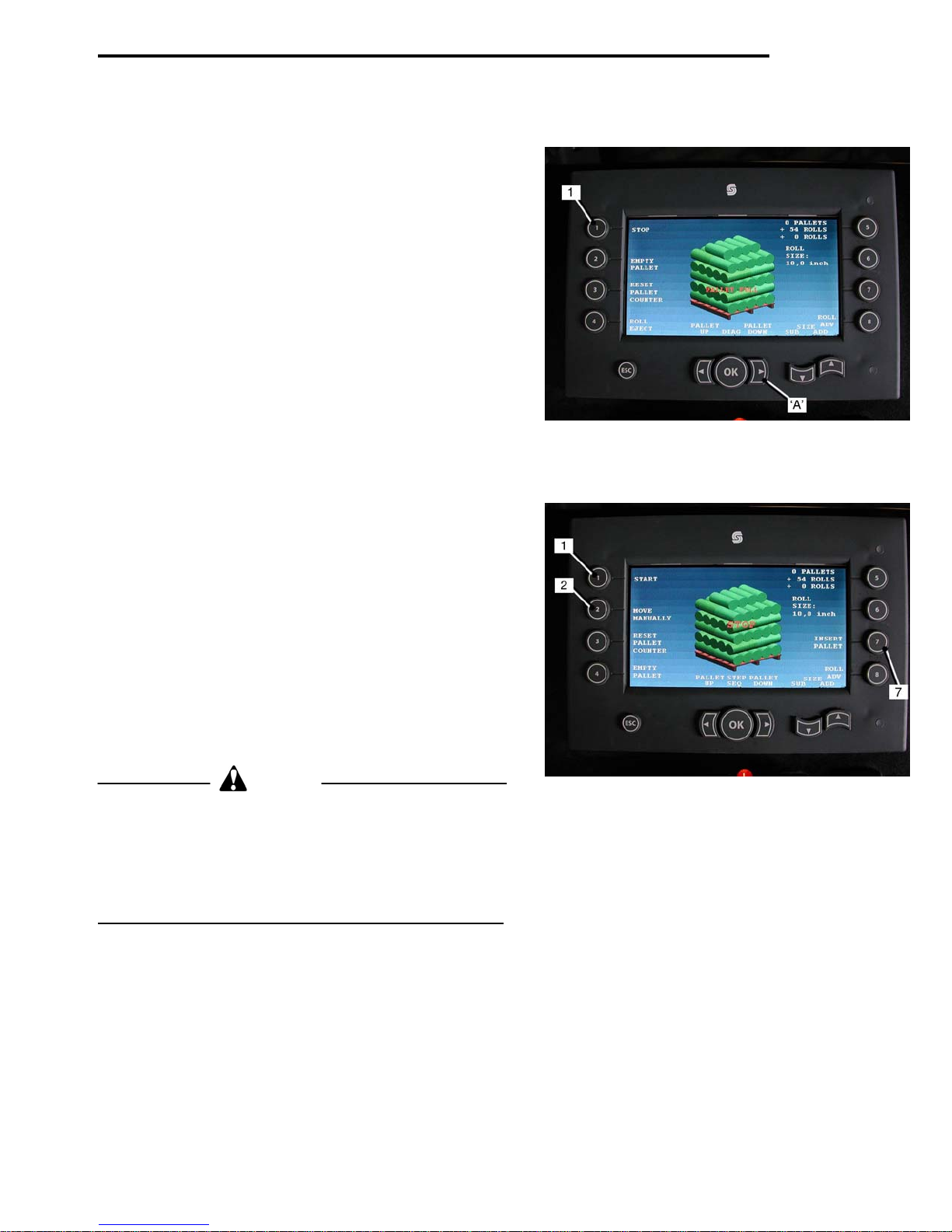
Pallet Dispenser
Screen 1.
• When the Pallet is ‘full’ and ‘Pallet Full’ is displayed
on the screen, press the ‘Right’ Arro
Down), and h
‘down’.
• Move the Harves
then stop the Harvester forward travel and press
Pad ‘1 ‘
Screen 2.
• Press
• Press
to the stacking position.
CAUTION
If seven rolls are on the Index Conveyor, the ‘FULL PALLET’ SCREEN 2.
must first be raised to the top position, using the
‘UP’ Arrow, or change the Index Conveyor number to lower
than seven, before p
Failure to do so will cause the Robotic Arm to start stacking
while the Forks are moving ‘UP’.
The hydraulic system will not respond fully in this case.
Pad ‘7’ (Insert Pallet). The pallet dispensing
sequence will start.
When the pallet has been dispensed onto the pallet
forks, press Pad ‘1’ (star
to Screen 1.
Pad ‘2’ (empty pallet) to raise the forks back
old down until the pallet is completely
ter forward, for two more cuts,
STOP’.
t). The display will return
ressing ‘EMPTY PALLET’.
w ‘A’ (Pallet
SCREEN 1.
Pallet
2-09
Page 32

Page 33

OPERATION
SECTION 3
Travel Speeds 3-1
Harvester Conveyor 3-2
4 Inch Feed Roller 3-2
Starter Tray 3-2
Starter Gate 3-2
Roll-Up Conveyor 3-3
Index Conveyor 3-3
Roll Flap – Stabilizer 3-3
‘Bad Roll’ Ejection 3-3
Robotic Arm 3-4
Gripper Head 3-4
Pallet Lift Forks 3-4
Pallet Dispenser 3-5
Pallet Specification 3-5
Pre-Operation ‘Warm-Up’ Procedure 3-6
Operating Instructions 3-7/3-9
Page 34

Page 35
OPERATION
TRAVEL SPEEDS
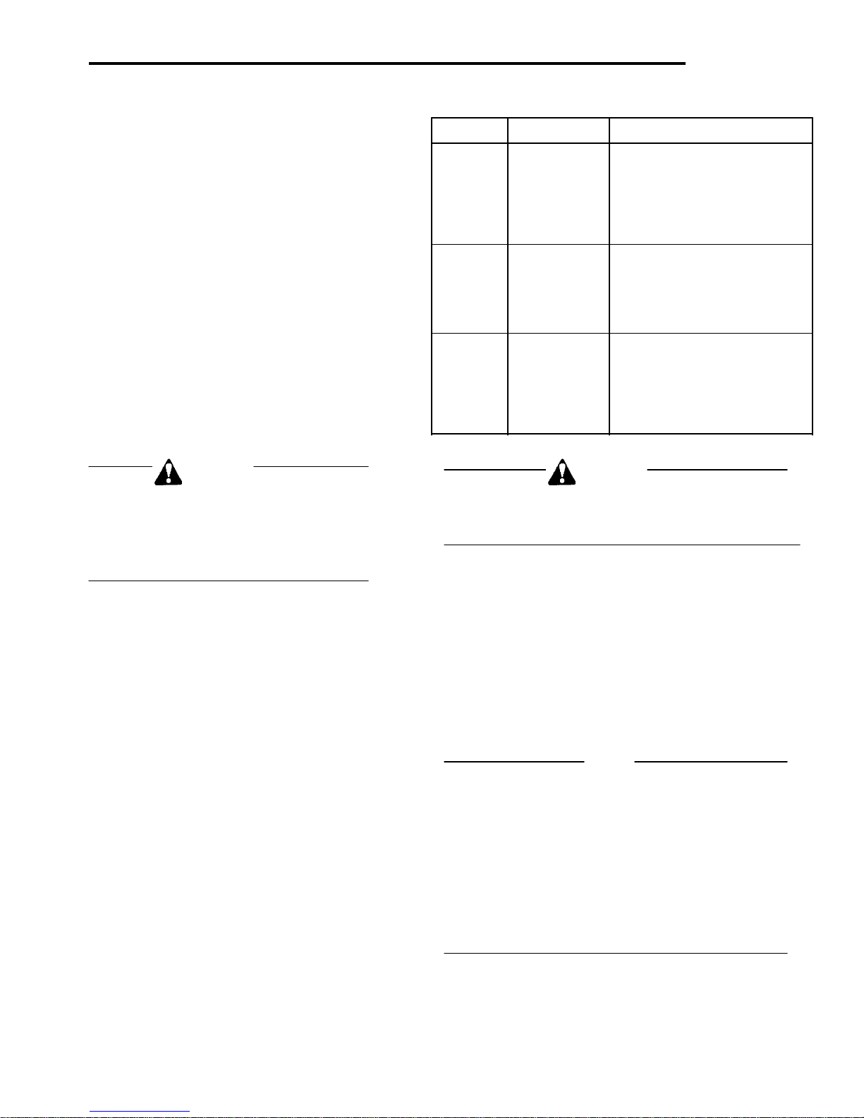
The Brouwer RoboMax Sod harvester is fitted to a RANGE GEAR TRAVEL SPEED (Kph./mph)
New Holland TLA Series tractor, built to Brouwer
specifications specifically for sod harvesting. 1 1.3 ( 0.82)
2 2.0 (1.23)
The RoboMax Harvester can be specified with
wheels or tracks. 4 4.0 (2.51)
When fitted with wheels, harvesting can be done
in Range 1, 1
1 3.1 (1.95)
If tracks are fitted, travel speed is reduced approx-
imately 50 %. 3 6.6 (4.11)
4 9.4 (5.85)
When harvesting with tracks fitted, operate in
Range 1, 3
2 10.7 (6.67)
Engine speed should be maintained at or above
1800 rpm to maintain adequate hydraulic flow 4 22.2 (13.80)
for the operation of the Robotic Arm.
st
or 2nd Gear.
rd
or 4th Gear or Range 2, 1st Gear. 1 7.4 (4.62)
1 3 2.8 (1.74)
11 2 4.5 (2.81)
111 3 15.5 (9.65)
CAUTION WARNING
The engine must be allowed to ‘idle’ for To prevent possible serious injury: No one should
5 to 10 minutes before switching ‘OFF’, to step on the conveyor, or attempt to remove to remove
allow the Turbo Unit to cool down. jammed turf rolls or debris, while the engine is running.
Failure to do so could result in serious
damage to the Turbo.
CUTTER BLADE MAIN CONVEYOR – SPEED SETTING
When starting to harvest, the Cutter Blade oper- The main Conveyor speed should be adjusted to provide
ation should be started before the Main Conveyor a space of four to six inches between the sod pieces as
and Cutter head are lowered to the ground to they travel up the conveyor. This initiates the actuation
reduce ‘shock loads’ to the Cutter Motor. of the Index Conveyor Sensor.
If the space between the sod pieces is less than four
The Main Conveyor and Cutting Head must be inches the sensor may not ‘see’ the end of the sod piece.
lowered ‘slowly to the ground, not ‘dropped’.
The lift Chain must be ‘slack’ at all times while
harvesting. NOTE
It may be necessary to adjust the Main Conveyor Speed
as the hydraulic system reaches operating temperature.
CUTTER BLADE – SPEED SETTING. When setting the Main Conveyor Speed, operate the
For best results, start cutting at the maximum tractor in the gear selection and at the engine RPM that
speed and work back to the lowest speed which will be used when harvesting.
provides the best results.
Lower operating speed results in less vibration. To keep the proper spacing between the sod pieces, as
they travel up the conveyor, maintain a constant travel
The tractor ground speed may have to be speed.
reduced when harvesting in rough or stony
ground, to avoid possible damage to the cutting
components.
3-01
Page 36
OPERATION
Harvester Conveyor
CAU
Safety Guards may have been removed for clarity.
Do not operate the Harvester with safety guards
missing or damaged.
To do so could result in serious personal injury.
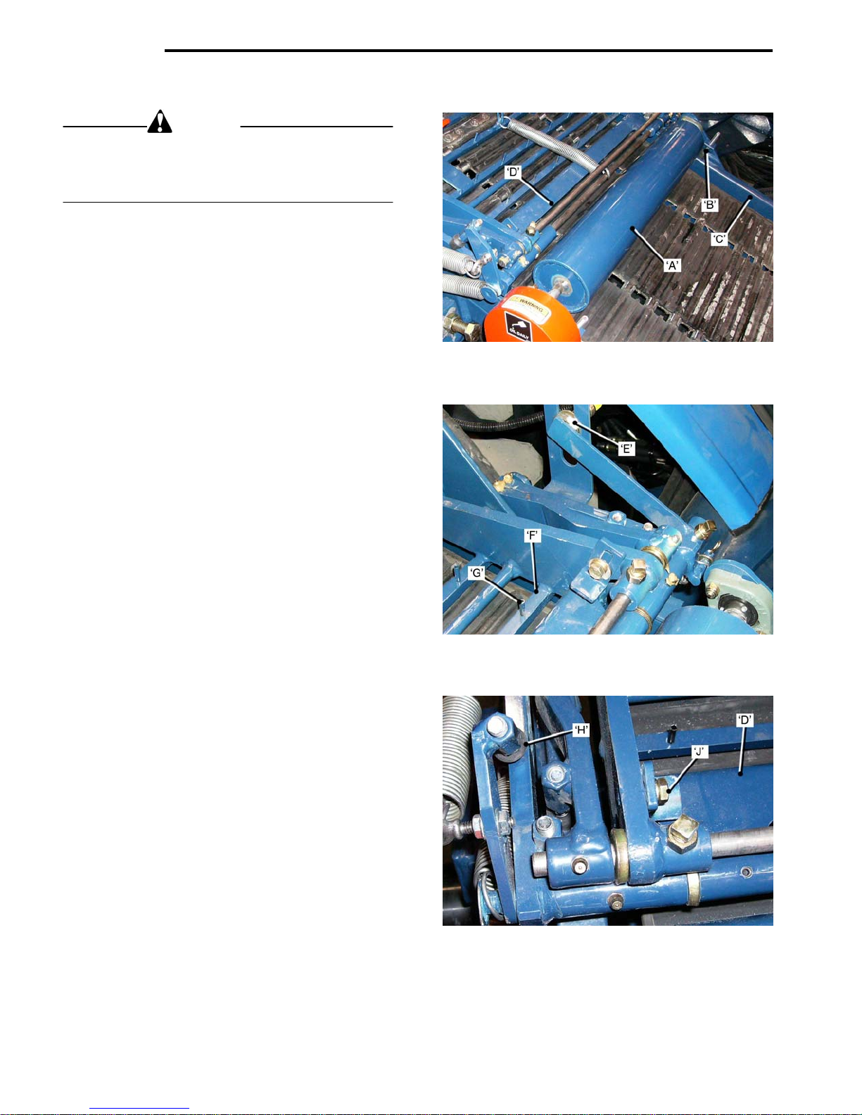
4 inch Feed Roller
The four inch Roller ‘A’ assists in feedi
the Starter Tray. It should be kept free of grass and
mud build-up to maintain proper operation.
The Roller is mounted on the Conveyor Mid-Idler and
is driven by the Main Conveyor Belt.
To adjust the Roller:
• Place a pie
Roller resting on the sod. Turn the Bump Stop
djusters ‘B’ until there is 1/8 inch clearance
A
between the Bump Stops and the Frame ‘C’.
• For wea
pressure, adjust the Bump Stops ‘do
the frame to raise the Roller and reduce pres-
ure on the turf.
s
Starter Tray
When the end of a slab of sod passes under the
Starter Gate ’D
Sensor ‘E’
• to count the n
• to ‘s
The first Bar ‘F
of Pins ’G’
The Pins grip the turf as it starts to ‘roll-up’.
If the turf passes through, but does not ‘roll-up’, tap
the Pins ‘IN’ until they protrude ½ to 5/8
The Pins wear with use and must be adjusted or replaced as required.
In tender sod the Pins may hold the underside of the
sod too long, causing a loose roll, incorrect Roll Flap
position, or partially folded ‘incompl
case the Pins should be ‘raised’.
Field trial will determine the best position of the Pins
for prevailing sod conditions.
• Maintain 4 to 6 inch
on the Conveyor.
• Do not allo
it will cause the Starter Gate to open early.
Starter Gate
The Starter Gate ‘D’ must be po
1/8 inch clear of the Conveyor Mat, measure at the join
plice’ in the Mat, ie. its thickest point
‘s
The Gate clearance is set with the adjusters ‘H’.
It must not touch the mat.
3-02
that signals the computer:
has pre-set
top’ the Eject Conveyor, that ejects
the Roll onto the Indexing Conveyor as the
Conveyo
that protrude through the Bar ¼ in.(approx.)
ce of sod under the Roller, with the
k, or thin turf, that require less roller
’ the Gate ‘drops’, activating a Proximity
r moves ‘back’ one position.
’ (behind the Starter Gate), has a row
w dirt to build up on the Conveyor,
TION
ng the sod into
wn’, onto
umber of teeth that the operator
in.
ete’ Rolls, in this
es between the sod pieces
sitioned approximately
The Starter Gate Stops ‘J’, must be adjusted so that
the bottom of the Gate is le
Bars in the Starter Tray.
vel with the bottom of the
Page 37
OPERATION
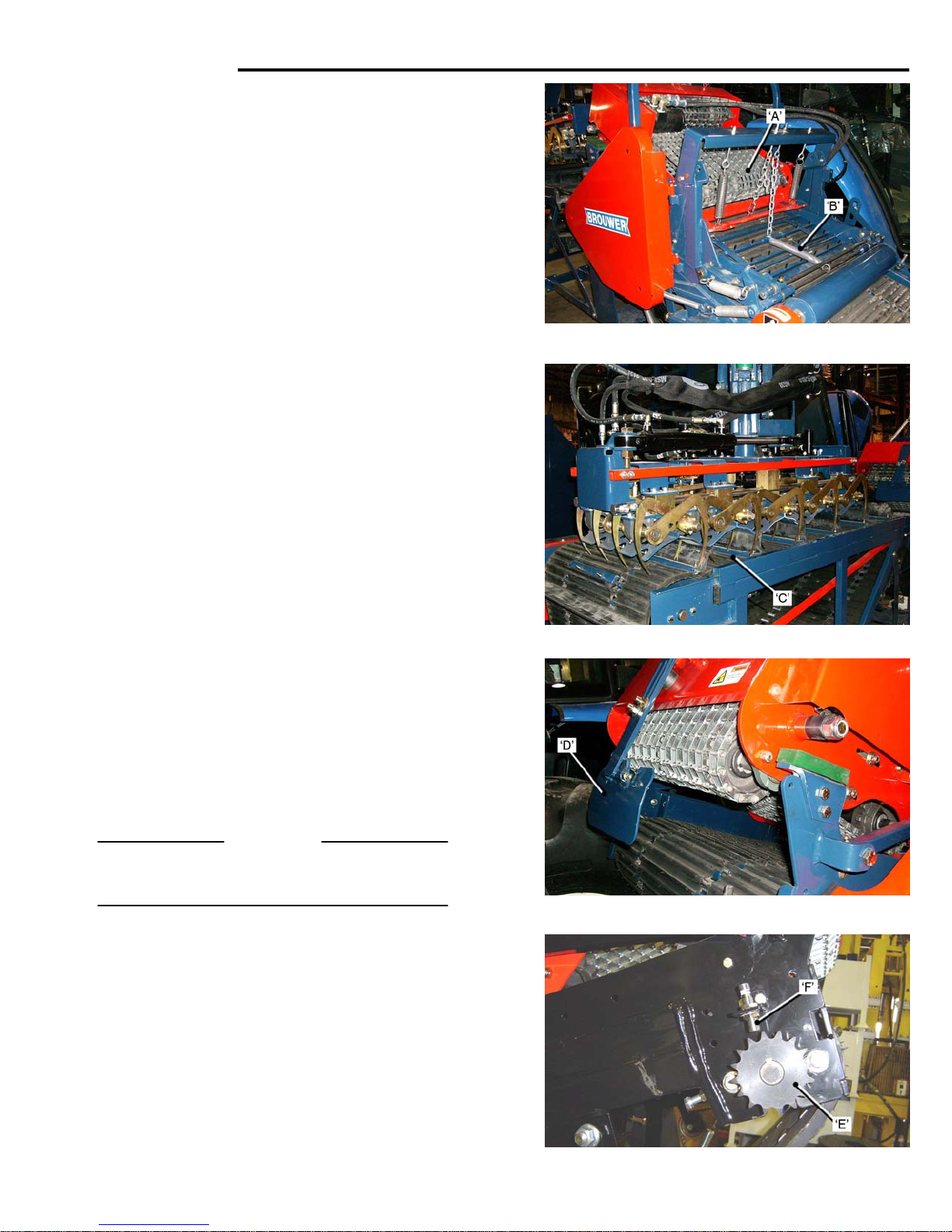
Roll-Up Conveyor
The Roll–Up Conveyor ‘A’, continues the Roll–Up
action after th
Tray ‘B’.
It is chain driven from the Main Conveyor.
Refer to Page 5-7 for adjustments.
Index Conveyor
The Index Conveyor is operated by Hyd
Its position is controlled by a Proximity Sensor.
The Index Conveyor ‘C’, is synchronized to the Main
Conveyo
When a Roll is ready to be deposited onto the Index
Conveyo
causes the Index Conveyor to roll back ‘one position’,
to accept the completed roll.
Roll Flap ‘Stabilizer’
The Roll Flap ‘Stabilizer’ ‘D’, holds the sod roll a
transferred to the Index Conveyor. The position of the
Roll Flap is controlled by setting the ‘tooth count,
using the ‘+’ and ‘-‘ Buttons on the Control Panel LED
Display, (see page 2-1).
The ‘teeth’ are on a Sprocket ‘E’, loc
rear of the Main Conveyor. They are ‘counted’ by a
Proximity Sensor ‘F’.
Increasing the ‘tooth count’ moves the Roll Flap
‘cou
nter clockwise’
Decreasing the ‘tooth count’ moves the Roll Flap
‘clock-wi
Adjust the Roll Stabilizer to suit the selected position of
the Roll Flap.
IMPORTANT
The Roll Fl
Roll. It must
Bad Roll Ejection
When a bad roll needs ejecting. The Index Conveyor
mbly is moved, and held back, allowing the Roll
Asse
to drop past the Conveyor to the ground.
To activate the Roll Ejection refer to the Controls
Section, pag
e Roll has passed through the Starter
raulic Motor.
r, Robotic Arm and Bad Roll ‘Ejection’.
r, a signal from the RoboMax Controller
s it is
ated at the left
se’
ap Stabilizer must be set to ‘just’ hold the
not ‘compress’ it.
e 2-5.
3-03
Page 38
OPERATION
Robotic Arm and Gripper Head
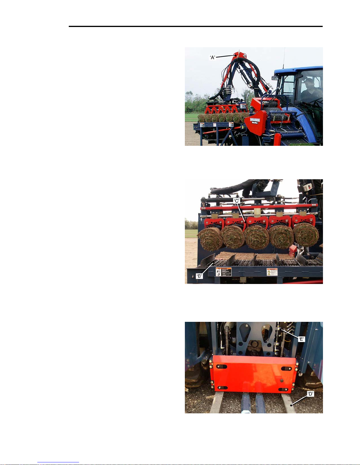
The functions of the Robotic Arm ‘A’ are controlled by
a Computer Controller, through Proportional Valves.
The Proportional Valves Stack Manifold is located on
the left rear fender.
The Controller provides positioning co-ordinates for:
• the Robotic
• the Rob
the Robotic Arm Rotation
• the Gripp
The Robotic Arm, in response to the Controller’s preprogrammed sequence for stacking, automatically
lifts the sod rolls from the Index Conveyor ‘B’ to the
Pallet.
Gripper Head
The Controller is also programmed to control:
• the ‘squ
the Gripper Fingers ‘C’.
Pallet Lift Forks
The Pallet Lift Forks ’D’ are
by the Controller, as the layers of sod are added to
the pallet.
When the stacking is complete, the loaded pallet
is lowered to the ground.
There are four Proximity Sensors ‘E’, that sen
three programmed positions of the Lift Forks.
• In the
on the pallet.
• In the
• In the
are added.
• Pallet ‘insert’.
3-04
Arm Lift
otic Arm Reach
er Head Rotation
eeze’ function and manipulation of
lowered automatically,
se the
‘upper’ position two layers are placed
‘middle’ position one layer is added.
‘lower’ position the remaining layers
Page 39
OPERATION
Pallet Dispenser
DANGER
Keep all bystanders clea
enter between the Pallet Dispenser and the Harvester.
To do so could result in serious injury or death.
Operating Position
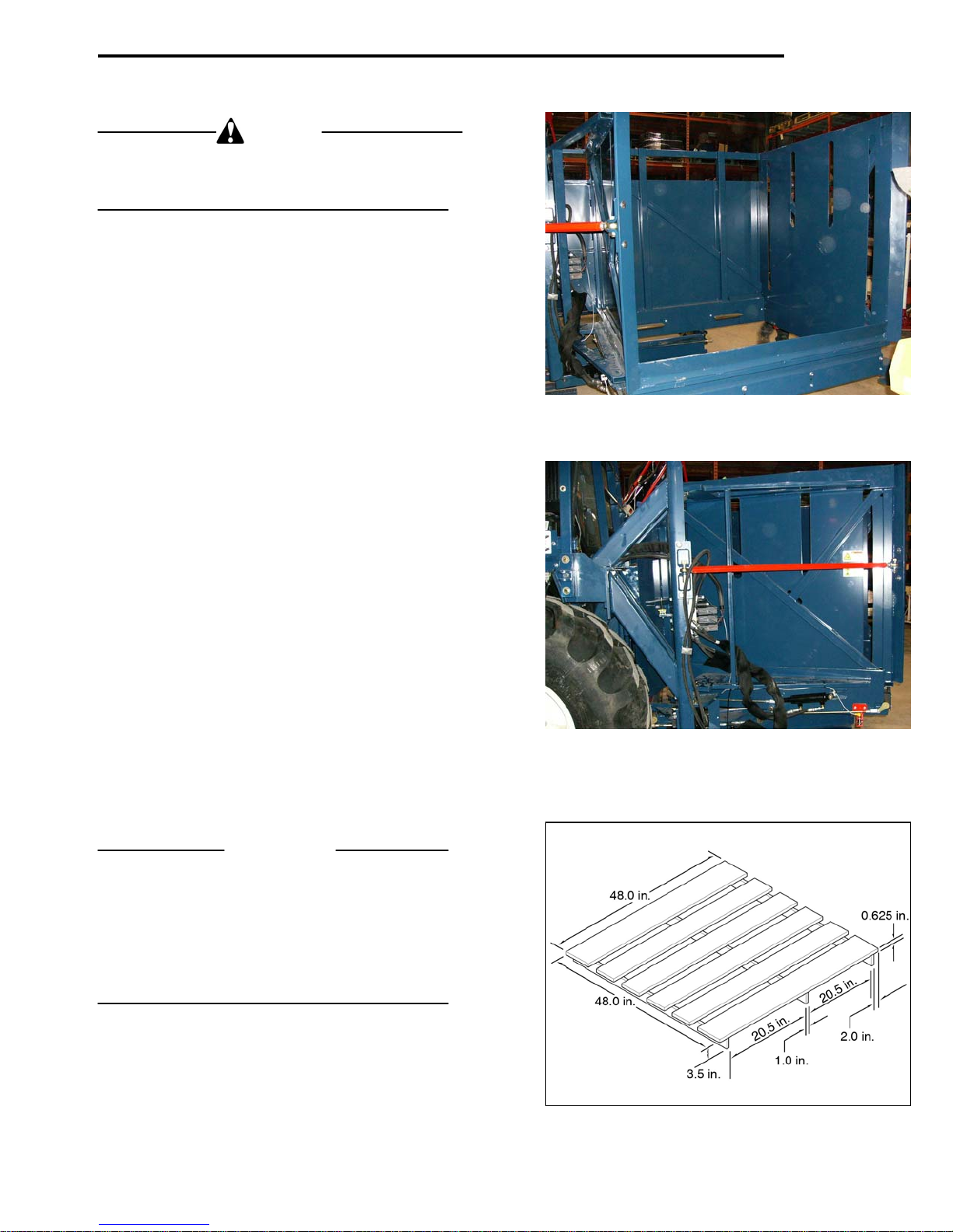
The Pallet Dispenser is located at the rear left side
of the Harvester. It holds up to 15 pallets, ready to
be transferred to the Lift Forks.
Pallet placement is controlled by ‘inputs’ from the
operator. (see Controls Section page 2-9).
Pallet ‘transfer’ operation is by hydraulic cylinders.
The cylinders are controlled by the Controller and
Proximity Sensors.
Stowed Position
The Pallet Dispenser Assembly can be ‘manually’
rotated from its operating position, to a ‘stowed’
position. This reduces the width of the machine,
for convenience when shipping or transporting.
Pallet Dispens
Pallet Specifications
IMPORTANT
To ensure proper operation of the Pallet Dispenser,
the Pallets must conform to the dimensions shown.
The pallets must be in good condition, with no loose
or broken boards.
The Pallet must be able to support 4000 lbs.
Pallet Specific
3-05
r, do not allow anyone to
Pallet Dispenser – Operating Position
er – ‘Stowed Position’.
ations
Page 40
OPERATION
PRE-OPERATION WARM-UP PROCEDURE.
DANGER
When carrying out the
of the machine. Failure to observe this precaution could result in serious injury or death.
IMPORTANT
Before operating the machine for harvesting it is important that the Hydraulic Oil is brought up to operating
temperature.
• Start the Tractor Engine a
System Power ‘ON’.
• Allow the Hyd
oil through the system, until the normal oil operating
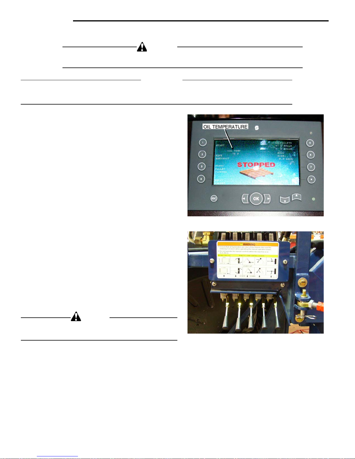
temperature is indicated on the temperature read-out
on the Control Panel Screen.
• Place the System in
Using the Manual Control Levers, at the rear left sid
machine, operate the following through several cycles.
CAUTION
To prevent damage to the Cut–off mechanism the Cut–off
must only be operated w
Manual Opera
The above procedure will:
• Ensure that the Machine
• Prevent po
• Serve to che
3-06
If the ambient temperature is below 75 deg. F, proceed as follows.
raulic Pumps to operate and circulate
‘manual’ mode.
• Rob
• Robotic
• Rob
• G
• Roll ‘Eject’.
otic Arm – Lift and Lower.
Arm – Rotation.
otic Arm – Extend.
ripper Head – Rotation.
hen the machine is harvesting.
ssible damage to components due to cold hydraulic oil.
ck that the machine is properly ‘set-up’ ready to operate.
following procedures all bystanders MUST BE KEPT CLEAR
nd switch the RoboMax
e of the
ting Controls
will function efficiently, with the Hydraulic Oil at the correct temperature.
Page 41

OPERATION
Operating Instructions.
NOTE
Refer
Functions’ instructions.
CAUTION
Before starting to cut the field, ensure that all by standers are clear of the area, an
no foreign objects or obstacles that may possibly
cause an accident.
If there is a ‘pause’ during the engine start presetting
action, it will result in the Controller and the Control
Display to go to the ‘Initial
this occurs they may get out of ‘synch’, and it will be
necessary to restart the tractor.
IMPORTANT
When the ‘Activ
to start harvesting. If the field has not been previously
cut, it will be necessary to cut a strip in the ‘manual’
mode to create the edge for the Auto-Steer Guide Shoe
to work against.
The initial strip must be cu
Auto-Steer operates properly.
Refer to Auto-Steer Section.
to the Controls Section for the ‘Controls
d that there are
• From the o
perator’s position place all controls
in ‘Neutral’.
• Inject a pallet
• Press the cl
onto the Lift Forks.
utch pedal to deactivate the
‘starting’ safety switch.
• Move the thro
ttle control to the ‘halfway’
position, and turn the ignition key to ‘START’.
Release the key when the engine starts.
NOTE
Start’ sequence twice. If
• Pull the ‘keyed’
(red) Harvester Switch ‘out’.
This will ‘enable’ the harvester functions,
except: Travel, Depth of Cut and Cutter Head
Position.
• Press
Pad ‘1’ on the Initial Start Screen, to
start the Controller. The Stacking Pattern
Selection will then be displayed on the screen.
• To sele
ct the required Stacking Pattern press
the ‘Prev’ or ‘Next’ Pads.
NOTE
There are four ‘s
tandard’ patterns.
e’ Screen is displayed you can prepare
t straight to ensure that the
• Lower the Cu
tter Head by moving the Main
Conveyor Control Lever ‘FORWARD’, until the
Conveyor Lift Chain is ‘slack’.
IMPORTANT
The Conveyor Lift Cylinder Safety Lock must
be
released before lowering the Cutter Head.
• Incre
ase the engine speed to 1800 RPM
minimum, to ensure sufficient hydraulic oil
flow.
Engine speed can be set at 1800
to 2400 RPM
when harvesting.
• Start the Cutter/Co
nveyor operation with the
Rocker Switch on the Control Panel.
Adjust the Main Conveyor speed with the
Control Knob
on the Control Panel.
The speed of the Main Conveyor must be adjusted
relative to the groun
d travel speed.
Recommended Conveyor speeds are shown below:
Wheel Equipped Units. Conveyor Speed
Range I. Ist.Gear ………………65 – 75 RPM.
Range I. 2
nd
.Gear…………………75 – 90 RPM.
Track Equipped Units.
Range I. 3
Range I. 4
Range II.1
rd
.Gear………………… 65 – 75 RPM.
th
Gear………………… 75 – 90 RPM.
st
Gear………………… 70 – 80 RPM.
Adjust the Conveyor speed to provide 4 to 6 inches
en the sod pieces on the conveyor.
betwe
The Tooth Count for the Index Conveyo
r also has to be
adjusted, relative to the ground travel speed, to ensure
that the Roll Flap is positioned correctly.
Tooth Count recommended starting point:
Wheel Driven Machines.
Range I. 1
Range I. 2
st
Gear 23 Teeth.
nd
Gear 20 Teeth.
Track Driven Machines
Range I. 3
Range I. 4
Range II.1
rd
.Gear 23 Teeth.
th
Gear 20 Teeth.
st
Gear 22 Teeth.
The above settings may require adjustment,
depending on prevailing ground conditions.
Cont…
3-07
Page 42

OPERATION
…cont
Transmission Operating Ranges.
• Select the re
using the ‘Range’ and ‘Shift’ Levers, located to
the right of the operator’s seat.
Transmission Operating Ranges are:
Wheel Driven Machines.
Range I. 1
Range 1. 2
Track Driven Machines
Range I. 3
Range I. 4
Range II. 1
• Move the Shuttle Lever (le
‘forward’ position – to select ‘forward’ Gears.
• Rele
ase the ‘PARK’ Brake and the Clutch
Pedal. The Machine will move forward and the
Cutter Head will be operating.
• Adjust the so
Lever. Move it ‘forward’ to ‘increase‘ the sod
thickness and ‘rearward’ to ‘decrease‘ the
thickness.
At this point the Rolling and Stacking process is automatic. Adjust
the sod to the thickness required, while
harvesting.
Defective Roll Ejection.
Defective rolls of sod can be ‘ejected
Pad‘4’ (Roll Eject) on Active Stacking Screen. It must
be pressed after the Roll has been placed, and the Index
Conveyor has stopped but before the next Roll enters
the Roll-up Conveyor.
The Index Conveyor moves ‘back’ allo
tive roll to drop to the ground.
The Index Conveyor will remain ‘back’ u
is ready to be placed on it, it then move ‘forward’
automatically.
NOTE
If there are areas of poor sod, or strips, that do not
re stacking, the Index Conveyor can be held in the
requi
‘back’ position allowing the sod to fall to the ground.
To hold the Conveyor ‘bac
the ‘1’ Pad (Stop). This will stop the stacking sequence
and prevent the Controller from sensing the ends of the
Rolls or Strips.
3-08
quired transmission configuration,
st
. Gear.
nd
. Gear.
rd
Gear.
th
Gear.
st
Gear.
ft Side), to the
d thickness with the Depth of Cut
’ by pressing
wing the defec-
ntil the next roll
k’, press the ‘4’ Pad and then
Stacking Sequence.
IMPORTANT
Do not ‘s
When the 40, 50, 60 or 70
top’ or ‘slow’ the engine while stacking
th
Roll, depending on the pallet
stack selected, is picked from the Index Conveyor, five
more rolls are needed to finish the pallet. A warning
lamp ‘blinks’ when there are three more rolls to go.
When the 5
th
piece of sod is cut and starts up the Main
Conveyor the operator must ‘stop’ the ‘forward’ travel
of the harvester.
The Robotic Arm picks up the rolls for the last layer after
th
Roll is placed on the Index Conveyor.
the 5
Pallet Full and Insert new Pallet.
After 44, 54, 64 or 74 Rolls, depending on the pallet
stack sele
cted, have been stacked on the pallet, the
‘Pallet Full’ Screen is displayed. Press the ‘Right
Arrow’ Pad (Pallet Down) to lower the completed pallet
to the ground. When the pallet is on the ground, continue
cutting (two more cuts),until the pallet is clear of the Lift
Forks. Stop the harvester and press the ‘stop’ Pad.
Refer to page 2-9 for the Pallet Dispense sequence.
Stopping the Stacking Sequence.
To stop the stacking sequence:
• Press
Pad ‘1’, on the ‘Active’ Screen, or press
the Harvester Switch on the Control Console.
It is recommended that the Stacking Sequence is
stopp
ed after the Robotic Arm has placed the Rolls
on the Pallet and returned to the ‘home’ position
over the Index Conveyor. This allows the Controller
to count the completed rolls.
If the stacking sequence is stopped, before the
otic Arm has completed the stacking cycle, the
Rob
Robotic Arm will not return to the ‘home’ position
until the stacking sequence is restarted.
After restarting the stacking seq
uence, the rolls that
were being stacked may be scattered when the Arm
returns to the ‘home’ position, it will then be
necessary to manually adjust the roll count on the
display.
Roll Count – Manual Adjustment.
To manually adjust the Roll Count:
• Press
Pad ‘1’ (Stop) on the Active Stacking
Screen. The Inactive Screen will be displayed.
• Press the ’O
K’ Pad (Step Sequence), this will
bring up the ‘Step Sequence’ screen, showing
a pallet with Rolls placed on it.
• The ‘Step Se
quence’ Screen indicates that the
‘Right’ Arrow’ is ’Next’ and the ‘Left Arrow’ is
’Prev’. These indicator Pads are used to ‘add’ or
‘subtract’ sod layers from the pallet.
Cont…
Page 43

OPERATION
IMPORTANT
If there were 15 Rolls on the Pallet, and the Robotic
Arm action
Rolls 16 to 20, after the sequence was re-started, and
Rolls 16 to 20 were manually placed on the pallet, it
would be necessary to go to ‘Step Sequence’, and
press the ‘Next’ Pad to add rolls 16 to 20 to the pallet.
was stopped at the mid point of stacking
If ‘forward travel’ was stopped, after the stacking sequence wa
adjust the number of Rolls on the Index Conveyor.
The Rolls will have to be manually re-positioned on the
Index Convey
move ‘back’ when the Stacking Sequence is stopped.
After the Rolls are positioned correctly on the Index
Conveyo
use the ‘Up’ and ‘Down Arrows’ Pads to adjust the
number of Rolls on the Index Conveyor, indicated
‘Plus’ and ‘Minus’ on the Screen.
Use the ‘Up Arro
(Minus), to adjust the number of Rolls shown on the
Screen Display, until they match the number of rolls on
the Index Conveyor.
When the number of Rolls on the Screen Display, the
Index Convey
Stacking Sequence can be re-started.
Restarting the Stacking Sequence.
If the Roll Count was manually adjusted:
If the Stacking Cycle was stopped after the Robotic Arm
had complete
position, over the Index Conveyor:
Partial Pallet
If a ‘partial pallet’ is required, that is a pallet with less
Roll
instructions below for the recommended procedure.
s stopped, it may be necessary to ‘manually’
or because the Index Conveyor will not
r, return to the ‘Step Sequence Screen’ and
w’ (Plus), and the ‘Down Arrow’
or and the Pallet are the same, the
• Press
• Press
• Re
• Press
s than the selected stacking pattern, follow the
• Whe
Pad ‘1’ (OK),to return to the Inactive
Stacking Screen.
Pad ‘1’ (Start), to start the stacking
sequence and return to the Active Stacking
Screen.
sume cutting, and the Stacking Cycle will
continue.
d its cycle and returned to the ‘Home’
Pad ‘1’ (Start), on the Inactive
Stacking Screen, to start the Stacking
Sequence and return to the Active Stacking
Screen.
n the Rolls required for the ‘partial pallet’
are on the pallet, ‘stop the forward’ travel of
the harvester.
• Press and ‘Hold’ Pad ‘5’, for ‘Full Pallet’
Screen, and then proceed normal operation.
Suggestions for better ‘Stacking’.
Brouwer incorporates the latest technology for mobile
equipm
its harvesters, to ensure that the customer has reliable
and user friendly automatic machines.
The operation of the Robomax Harvester is straightforwa
field conditions, require that the operator is aware at all
times of such variations.
The following suggestions will help the operator to
‘stack’ con
3-09
ent, in the electronics and hydraulic systems on
rd, however, variations in sod rolls and in the local
sistent pallets of sod.
• The ‘integ
pends on the consistency and quality of the
sod rolls. Poor quality rolls result in pallets with
low integrity. It is important
maintains roll consistency and grades the rolls
as they are harvested. Inferior rolls should be
‘ejected’ before the Robotic Arm transfers rolls
to the Index Conveyor.
• Roll si
position on the pallet are related. To stack a
pallet correctly, The Gripper Head should
come ‘down’ to just touch the rolls on the Index
Conveyor, before the Gripper Fingers ‘close’
and grab the rolls. This pick-up height is
adjusted by selecting the correct roll size on
the display screen.
• Selecting a ‘t
Robotic Arm to compress the rolls as they are
picked from the Index Conveyor and
transferred to the pallet.
Compression of the rolls when being stacked
results in in
efficiency.
• Selecting ‘too large’ roll si
being ‘dropped’ onto the pallet. This leads to
pallets with less than the desired integrity.
Adjustments can be made to the ‘stacking positions’. To det
• Harve
specific stacking position that may require
adjusting. If the five pallets show the same
stacking inconsistency, stacking position
adjustment is necessary.
Consult your Brouwer Dealer, or the Factory,
for advice o
rity’ of a stacked pallet of sod de-
that the operator
ze,(diameter), and their vertical stacking
oo small’ roll size commands the
creased cycle times and reduced
ze results in the rolls
ermine if adjustment is necessary:
st at least five pallets of sod, noting the
n this procedure.
Page 44

Page 45

MAINTENANCE
SECTION 4
Maintenance.
Maintenance Schedule 4-1
Hydraulic System 4-2
Hydraulic Oil Specification 4-2
Hydraulic Oil Filters 4-3
Manifolds and Valve Stacks 4-4
Main Motor Manifold 4-4
Index Conveyor - Flow Control
Gripper Head/Pallet Lift Forks Manifold 4-4
Proportional Valves Stack 4-5
Conveyor Lift Safety Lock 4-6
Cutter Drive . V-Belt 4-6/4-7
Crankshaft Assembly 4-8/4-10
Main Conveyor Drive 4-11
Crown Roller 4-11
Mat Tension Idler 4-11
Mid-Idler Mat Support. 4in. Roller Drive 4-11
Rubber Conveyor Mat – Splices and Clips 4-12
– Installation 4-13
Mintex Metal Mat 4-14
Rubber Conveyor – Mat Sliders 4-15
Roll-up Conveyor Stops 4-15
Blank page. 4-16
Lubrication Points 4-17
Orifice replacement 4-4
Page 46

Page 47

FIRST EVERY EVERY EVERY EVERY
Maintenance Procedure DAILY 25 50 100 250 750
HOURS HOURS
ENGINE.
Refer to the Tractor Manufacturers Man
Check/Top-off Engine Coolant Level. X
Check/Top-off Engine Oil Level. X
Check for Water/Oil Leaks. X
Clean Air Intake Screen.
Clean Radiator Cooling Fins. X
Clean Air Cleaner Pre-cleaner.
Clean Air Cleaner Element. Refer to
Change Engine Oil and Filter.
HYDRAULIC SYSTEM.
Check for Oil Leaks. X
Top-off Oil Level. X
Change Hydraulic Oil.
Change Main In-Tank Filter
Change High Pressure Filter. X
MACHINE
Check Fasteners and Fitting. X
Check Chains and Sprockets. X
Check Tire Pressure.
Front Tire Pressure. 30 psi. Left Rear Tire is ballasted
Right Rear Tire Pressure. 34 psi.
Left Rear Tire Pressure.18 psi.
Check/Sharpen/Repl.Cutter Hd. Blades.
Check Top-off Battery.
Check/Adjust /Replace Cutter Drive Belt.
Check Conveyor Belts.
Check Main Conveyor Slides.
Check Lug Nut Torque –To 188 ft.lbs.
STORAGE: Maintain Pro
4-01
X
NOTE
x balance conveyor weight. A special Gauge is required to check
x
x
x
x
per Tire Pressure. Remove Battery and Maintain Charge. Grease Hydraulic Cylinder Rods.
ual for additional maintenance information and instructions.
the Tractor Manufacturers Manual.
X
X
with Calcium Chloride solution to
the pressure in liquid filled tires. See your Dealer.
x
x x
HOURS HOURS
X
Page 48
MAINTENANCE
HYDRAULICS
Hydraulic System.
At the factory the Hydraulic System is filled with
PETRO-CAN HYDREX XV
Oil. It is a Premium performance, long life, anti–wear
hydraulic fluid.
IMPORTANT
Use ONLY recommended oil.
The Specification Chart below shows the typical
racteristics of HYDREX XV.
cha
Contact your local oil dealer, for an oil that has the
same characteristics, if HY
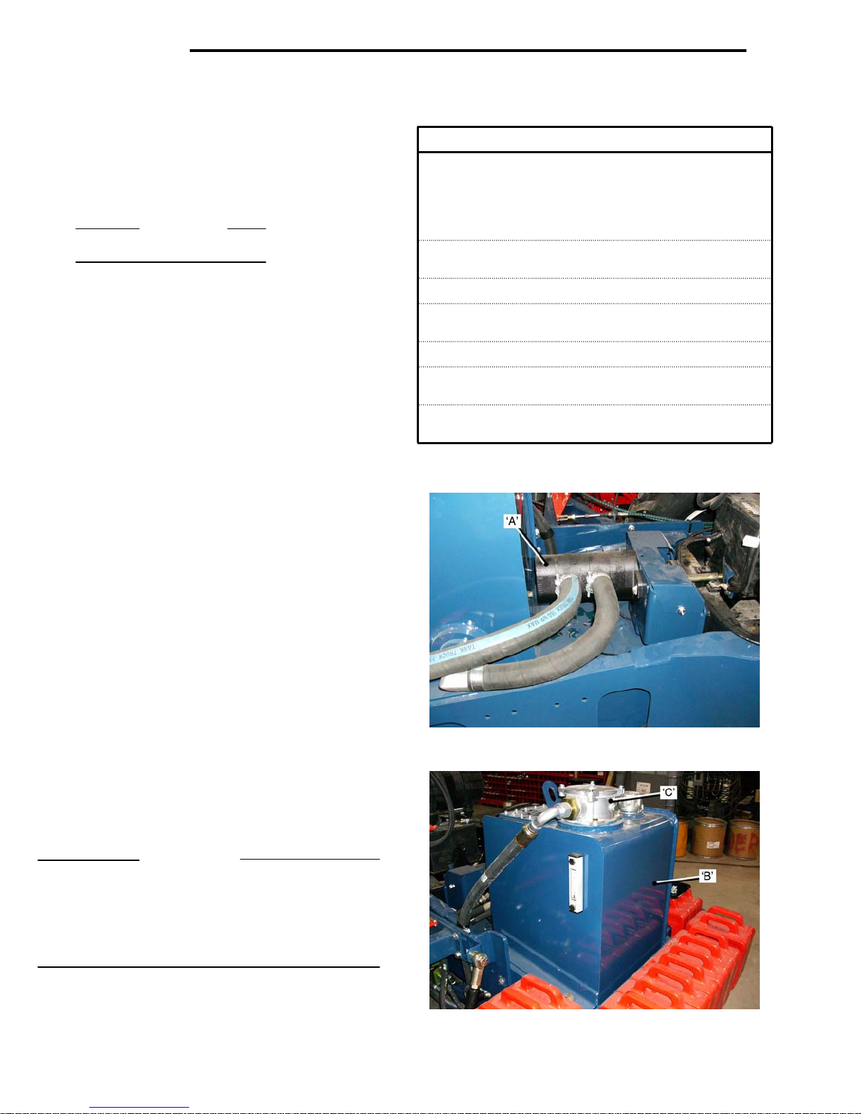
The RoboMax Hydraulic System uses a three section
Hydraulic Pump ‘A’, to sup
Cutter Head, the Conveyors, Pallet Lift, and the
Robotic Arm.
The pump drive is from the front of the tractor engine.
Internal tractor hydraulics operate the Main Conveyor,
Cutter
The Hydraulic Tank ‘B’, m
Harvester, contains hydraulic oil for the external
hydraulics. The Main Filter ‘C’ mounts in
Oil Coolers with electric fans are provided to keep the
oil temperature within the operating range.
The Cooling Fans will switch on automatically when
the oil rea
sending unit in the hydraulic tank.
All external hydraulics are routed through manifolds
that direct the oil flow to the Motors and Cylinders.
Each manifold is marked to aid in the hose routing
and trouble shooting.
Their are several bulkheads where hoses connect.
These bulkheads are labeled with hose locations and
the hoses a
routing.
IMPORTANT
To prevent serious damage to the Hydraulic System
do not allo
enter the System.
When working on/repairing hydraulic components
thorou
Cap and plug all broken connections.
4-02
Head Lift and the Depth of Cut.
ches a set temperature, measured by a
re marked with part numbers to aid in hose
w water, dirt, debris or contaminants to
ghly clean around the area to be worked on.
- All Season Hydraulic
DREX XV is not available.
ply hydraulic power to the
ounted at the front of the
to the tank.
HYDREX XV. OIL. Specifications.
Viscosity cSt @ 40deg. C 43.2
cSt @ 100deg.C 10.5
SUV @ 100deg. F 201
SUV @ 210deg. F 61
Viscosity Index. 245
Flash Point. Deg.C/Deg.F
Pour Point. Deg.C/Deg.F
Oxidation Stability, hours to 2.0 TAN. 10,000 +
Min. Start-up Temp. Deg.C/Deg.F
Operating Range. Deg.C -18 to 75
Deg.F 0 to 167
245/473
-48/-54
-40/-40
Page 49
MAINTENANCE
Hydraulic System.
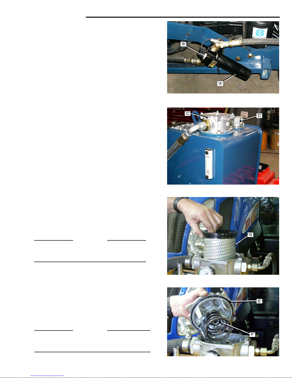
High pressure Filter.
For additional protection to the Proportional Valves,
that control the Rob
‘A’, is installed between the Hydraulic Tank and the
Proportional Valves. It is mounted on the left side of
the tractor, aft of the left front wheel.
The Filter Cartridge should be change after the initial
25 hours
at any time the Gauge ‘B’ on the Filter indicates that
the filter efficiency is reduced. When the Filter
Cartridge reaches this point, a switch in the filter head
‘closes’, and the ‘RED’ Indicator Flag is activated. Also
a signal is sent to the Control Panel Display to warn
the operator that ‘filter service’ is necessary.
Main In–Tank Filter.
It is recommended that the In-Tank Filter Element is
cha
IMPORTANT
When the Filter or Filler Cap are removed during
servi
debris or other contaminants from entering the tank.
It is recommended that the Hydraulic Oil is changed
very 750 hou
changed.
IMPORTAN
To ensure maximum cooling, do not stack sod on the
front tracto
add more weights, or ballast the front wheels.
of operation, and then every 100 hours, or
nged every 750 hours.
• Before loo
open the Filler Cap ‘D’ to relieve tank
pressure.
• Press
spring pressure, at the same time turn it
‘counter clockwise’ to remove it.
• Check the Top Plate O-Ring ‘E’. Replace it if it
is damaged.
• Clea
• Remove the
• Refit the Top
ce, cover the tank openings to prevent any dirt,
• Always d
• Clea
• Refill the tank using o
• Fill to the correct level indi
n the Magnet ‘F’ of any metallic residue.
Install a new Cartridge. Check that the O-Ring
is correctly seated in the Top Plate and all
surfaces are clean.
turning ‘clockwise’ to locate it against the bolts
and tighten the bolts.
rs or annually, when the Main Filter is
container.
n and replace the ‘magnetic’ drain plug.
hydraulic oil as shown on page 35.
Glass ‘H’, on the oil tank. DO NOT overfill.
r weights. If more front weight is needed
otic Arm, a High Pressure Filter
sening the bolts in the Top Plate ’C’,
‘DOWN’ on the Top Plate, against
used Cartridge ‘G’ from the tank.
Plate by pressing ‘DOWN’ and
rain the oil into an approved
nly an approved
cated on the Sight
T
4-03
Page 50
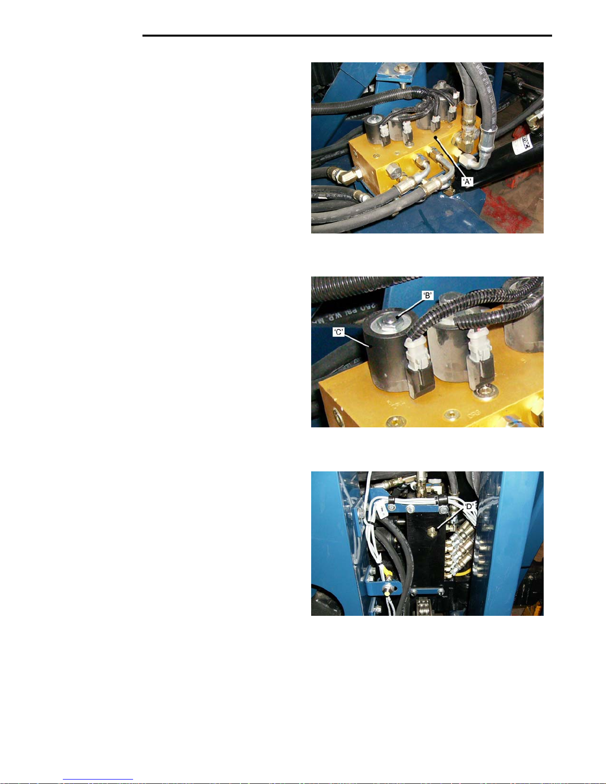
MAINTENANCE
Hydraulic System.
Manifolds and Valve Stacks.
Main Motor manifold.
The Main Motor Manifold ’A’, is located
side of the tractor between the Conveyor and the
Tractor.
The Motor Manifold receives approximately 15 gallons
per min
Pump. The flow is then directed through Solenoid
Valves in the manifold, to the:
Relief pressure in the manifold is set at the factory at
2650 p
Index Conveyor Flow Control Orifice.
If the Index Conveyor movement slows noticeably the
fault may be with the Flow
under the Index Conveyor Spool.
To install a new Orifice:
Gripper Head/Pallet Lift Forks Manifold.
The Gripper Head/Pallet Lift Forks Manifold ‘D’ is
locate
Cylinder. It receives approximately 7 gallons per
minute
from the front section of the Hydraulic Pump. The flow
is then direct
the manifold to the:
Relief pressure in the manifold is set at the factory at
1500 p
A check valve limits the pressure to the Gripper fingers
to 900 psi.
4-04
ute from the ‘center’ section of the Hydraulic
• Cutter Head Motor.
• Main Co
• Roll-up Conv
• Index Convey
si.
• Remov
• Use a Hex Socket to ca
Valve/Spool Assembly from the Manifold.
• Use a magn
faulty Orifice from the Manifold.
• Install the ne
• Che
Valve/Spool Assembly is not damaged,
replace if necessary.
• Scre
Manifold.
• Refit the Coil
to 12 ft.lbs. Do not over-tighten the Nut as it
may result in damage to the Coil.
d in front of the right side Pallet Forks Lift
• Gripp
• Gripp
• Pallet Lift Fork
si.
nveyor Motor.
eyor Motor.
e the Nut ‘B’, and the Coil ‘C’.
et to ‘reach in’ and remove the
w Orifice.
ck that the O-Ring under the head of the
w the Valve /Spool Assembly into the
ed, through solenoid operated valves in
er Head Fingers.
er ‘Squeeze’ Function.
or Motor.
Control Orifice located
refully unscrew the
‘C’, and Nut ‘B’. Tighten the Nut
s Cylinders.
on the right
Page 51
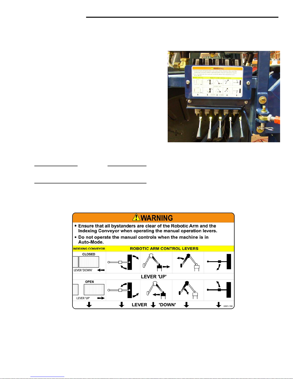
MAINTENANCE
Hydraulic System.
Proportional Valves Stack.
The Proportional Valve Stack Assembly is mounted
above the left rear
30 gallons per minute from the ‘rear’ section of the
Hydraulic Pump.
The oil flow is directed through four of the valves, to
the Hydra
the Robotic Arm.
There is also a valve that control
Roll Eject.
All functions are controlled by the on-board computer.
The Proportional Valves can also be ‘manually’ operated for the Robotic Arm
This may be necessary if the computer is malfunctioning, when the system is set to ‘manual mode’, or
during service procedures.
Relief pressure in the manifold is set at the factory at
2700 p
IMPORTANT
Do not change the relief valve pressures, unle
authorized by the factory service department.
ulic Cylinders that control the functions of
si.
wheel. It receives approximately
s the operation of the
and the Index Conveyor.
ss
4-05
Page 52
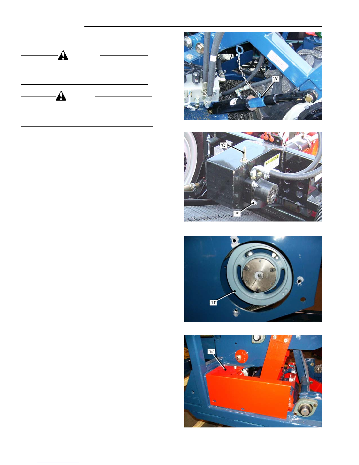
MAINTENANCE
Conveyor Lift Safety Lock.
WARNING
To prevent possible serious injury the Conveyor
Lift Cylinder Lock must be
on the Cutter Head in the raised position.
CAUTION
To prevent possible damage to the machine, when
the Cutter Head is raised for transport, the Conveyor
Cylinder Lift Cylinder Lock must be in place.
The Safety Lock ‘A’ is installed to prevent the Lift
Cylinder retracting, from accidental operation, or from
loss of hydra
Raise the Conveyor ‘fully’ to fit the Cylinder Lock
into place.
Cutter Drive – V-Belt. Remove/Install.
• Rai
• Loo
• Remov
• Remove the
4-06
ulic pressure.
se the Cutter Head and place the Cylinder
Lock ‘A’ in position.
sen the Drive Motor Mounting Bolts ‘B’,
and the Drive Belt Tension Adjuster ‘C’.
Push the Motor ‘down’ to
Belt.
e the Drive Motor Housing Cover,
and remove the Belt from the Sheave ‘D’
the Connecting Rod.
in place when working
slacken the Drive
Cutter Arm Cover ‘E’, to access
Page 53
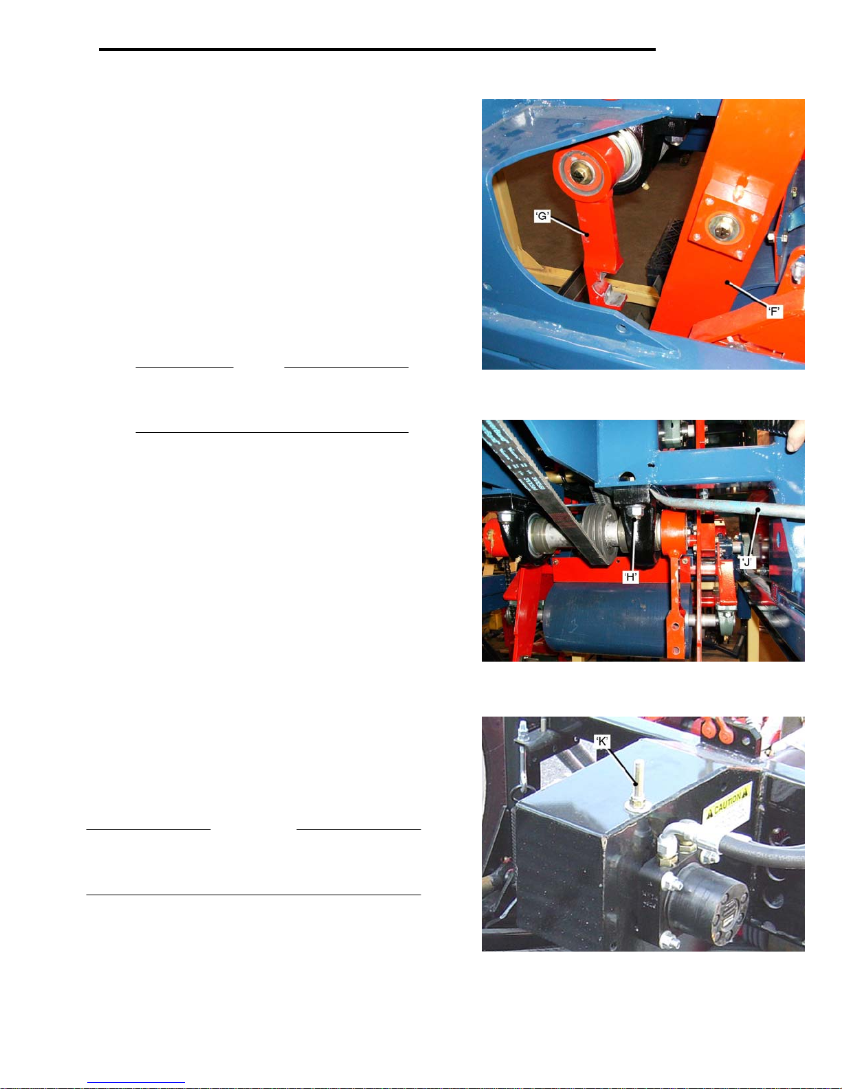
Cutter Drive Belt – Remove/Install.
• Pull the Cutter Arm ‘F’ ‘back’.
Remove the top section of the Connecting Rod
g Cap, and allow the Connecting Rod ’G’
Bearin
to swing ‘downwards’.
• Remove the
Bearing Bolts.
NOTE
Use a ’crowfoot’ wrench to hold the head of the
r bearing bolt. (It is difficult to reach because
rea
of the Tension Spring).
Use a ‘pry-bar’ ‘J’, to lever the beari
to remove the Drive Belt.
Install the new Drive Belt and re-assemble in the
revers
e order. Take care to tighten all fasteners to their
correct torque.
To adjust the tension of the Drive Belt:
• With the Drive Motor mou
turn the Drive Belt Adjusting Nut ‘K’ clockwise
to tension the belt, until there is ¼ to 3/8 inch
de-flection at a point midway between the Drive
Motor and the Crankshaft sheaves.
• Tighten the m
replace the cover plate.
IMPORTANT
Do not over tension the Drive Belt, as this may result in
ature wear and motor bearing failure.
prem
Check the belt tension after 20 to 30 hours of operation.
Nuts ‘H’ from the Crankshaft
ng ‘down’ sufficient
nting bolts ‘loose’,
ounting bolts locknuts and
MAINTENANCE
4-07
Page 54
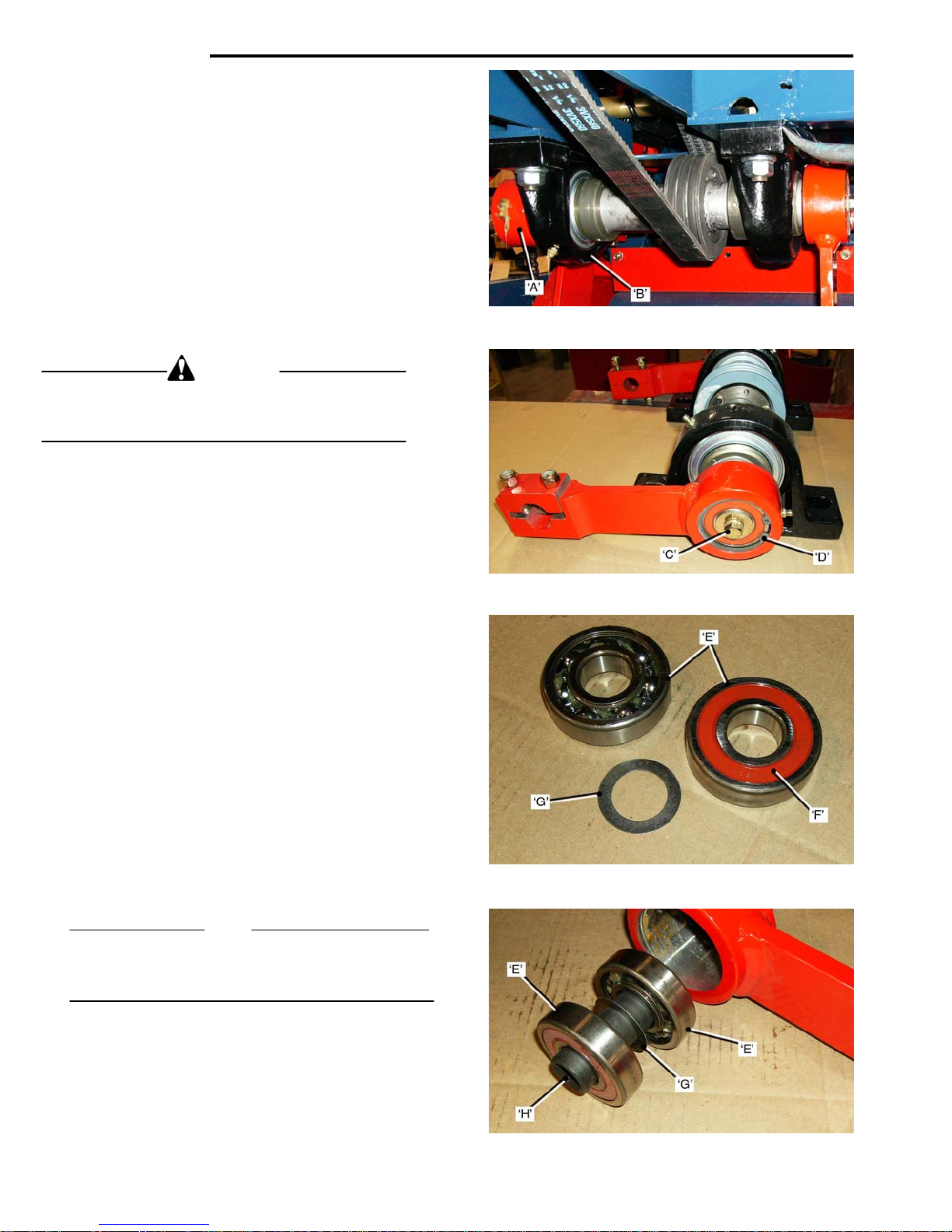
MAINTENANCE
To Service Crankshaft/Connecting Rods Assembly.
Remove Crankshaft Assembly
To remove the Crankshaft/Connec
follow the instructions for removing the Drive Belt, as
shown on pages 4-6 and 4-7. (16/18 in.ass’y.shown).
From that point proceed as follows:
• Remove the l
Cap ‘A’ .Let the Connecting Rod swing ‘down’.
• Remove the
Crankshaft Bearing ‘B’, and remove the
Crankshaft Assembly.
CAUTION
To prevent possible injury to the hands, exercise care
n removing the Crankshaft Bearing fasteners.
whe
The Crankshaft Assembly is heavy. Lower it carefully.
To remove the Connecting Rod Bearings:
• Remove the
Use a ‘Puller’ to remove the Connecting Rod
and Bearings from the Crankshaft.
• Remove the
Bearings ‘E’, out of the Connecting Rod.
To install new Bearings:
Before installing new bearings the Grease Seal ’F
one side of the bearing, must be removed. Pack the
bearings with grease. Bearings must be installed with
the remaining Grease Seal facing ‘out’.
• Fit one Snap
until it ‘just’ contacts the Snap Ring. Do not
apply too much pressure as it may damage the
Snap Ring and/or the Ring Groove. To prevent
damage to the Bearings, always press them ‘IN’
by the ‘outer’ race.
• Install the Shim ‘G
• Press-i
Snap Ring.
NOTE
Use a ‘Dummy’ Shaft ‘H’, to cente
Bearings. The Shim separates the Bearings allowing
grease to reach the bearings.
4-08
eft hand Connecting Rod Bearing
Lock-nuts from the left side
Connecting Rod Retainer Bolt ‘C’.
Snap Rings ‘D’, and press the
Ring ‘D’ and press in a Bearing ‘E’,
’. See note.
n the second Bearing and fit the second
ting Rods Assembly,
’, on
r the Shim in the
Page 55
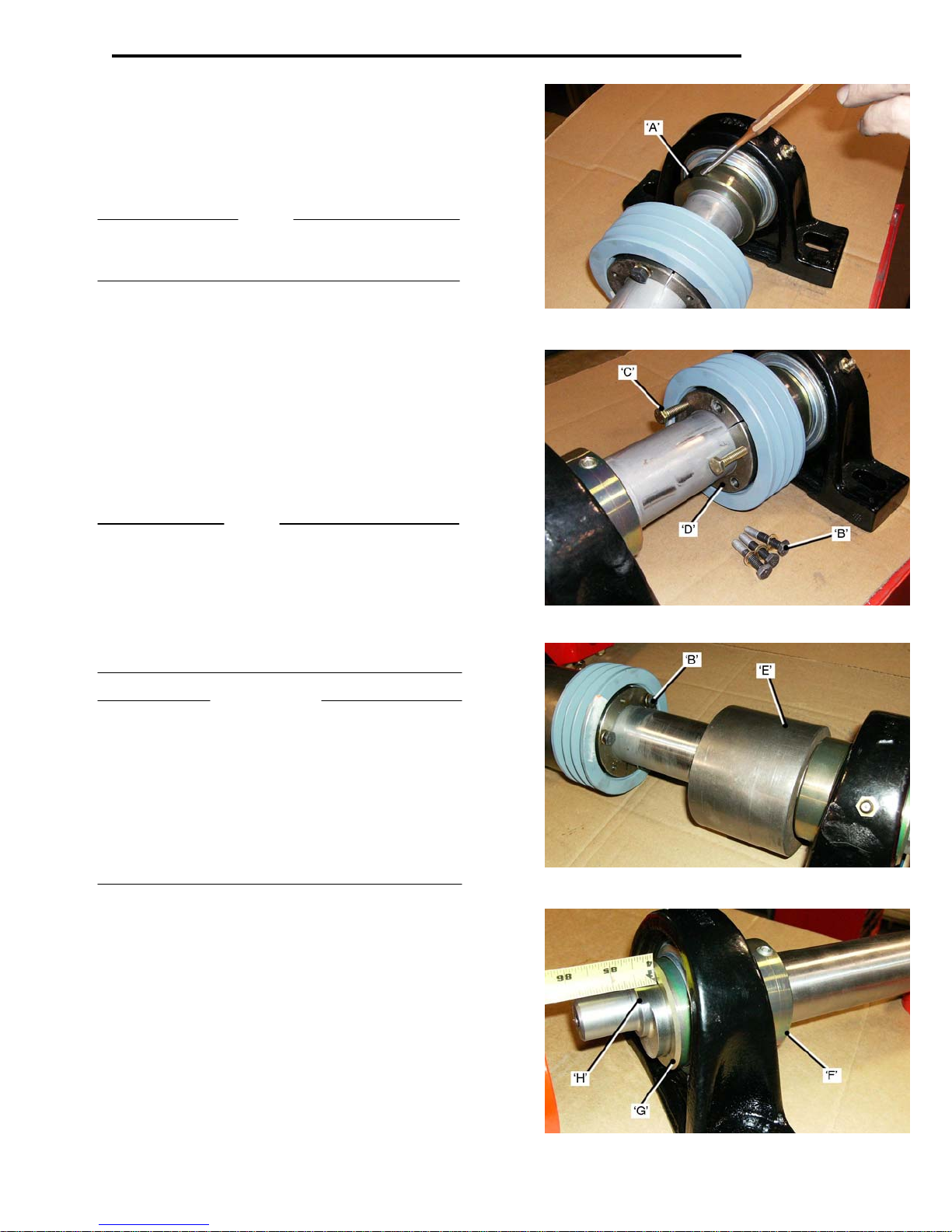
MAINTENANCE
Crankshaft Bearings and Sheave.
To remove the Crankshaft Bearings:
• Remove the
• Back-off the Lock-Coll
• Use a suita
Lock-Collar ‘A’.
NOTE
Lock-collars are ‘tightened’ in the directi
and released in the opposite direction.
Connecting Rods. See page4-8.
ar Set Screw.
ble Drift or Punch to
release the
on of rotation,
• If the Crankshaft is to be re-used, carefully
clean-up the shaft ends, where the Connecting
Rod Bearings fit, and remove the Crankshaft
Bearings.
To remove/install the Crankshaft Sheave:
• Remove the t
• Fit three bolts into the threa
and tighten them ‘evenly’ to release the Taper
Lock Bushing ‘D’.
Remove the Sheave from the Shaft.
NOTE
Apply ‘Anti-Seize’ to the Crank Shaft when fitting the
Bearings and Sheave, to ease assembly and prevent
rust/corrosion forming.
When fitting a new Sheave, slide it onto the Shaft, but
do not tighten the Taper Lock Bushing Bolts, it will have
to be aligned with the Drive Motor Sheave when the
Crank-Shaft Assembly is installed in the frame.
IMPORTANT
If the Crankshaft Assembly is for a 24 inch machine
the Driven Sheave m
Bushing Facing as shown. This gives clearance from
the Counter Balance Weight ‘E’ and allows the Bush
Bolts ‘B’, to be remove
Also Shim Plates are fitted between the Bearings and
the Frame to prevent the Counter Balance Weights from
‘jamming’ against the frame.
See page 4-10 for removal of Counter-Balance Weights.
Fitting new Crankshaft Bearings:
• Check that the Shaft is free of scratches, marks
or rust, that will hinder assembly.
• Fit the Bearings
Collars ‘F
• Position the
½ inch from the shoulder ‘H’ on the
Tighten the Lock-Collar ‘A’ and the Set Scre
Fit the Connecting Rods, Washers and Retainer Bolts
onto the Crank-Shaft.
The assembly can now be installed into the frame.
hree Bushing Bolts ‘B’.
ded holes ‘C’
ust be fitted with the Taper Lock
ing
d/replaced.
onto the Shaft, with the Lock-
’ facing ‘inwards’.
Bearings as shown, with the face ‘G’
shaft.
w..
4-09
Page 56
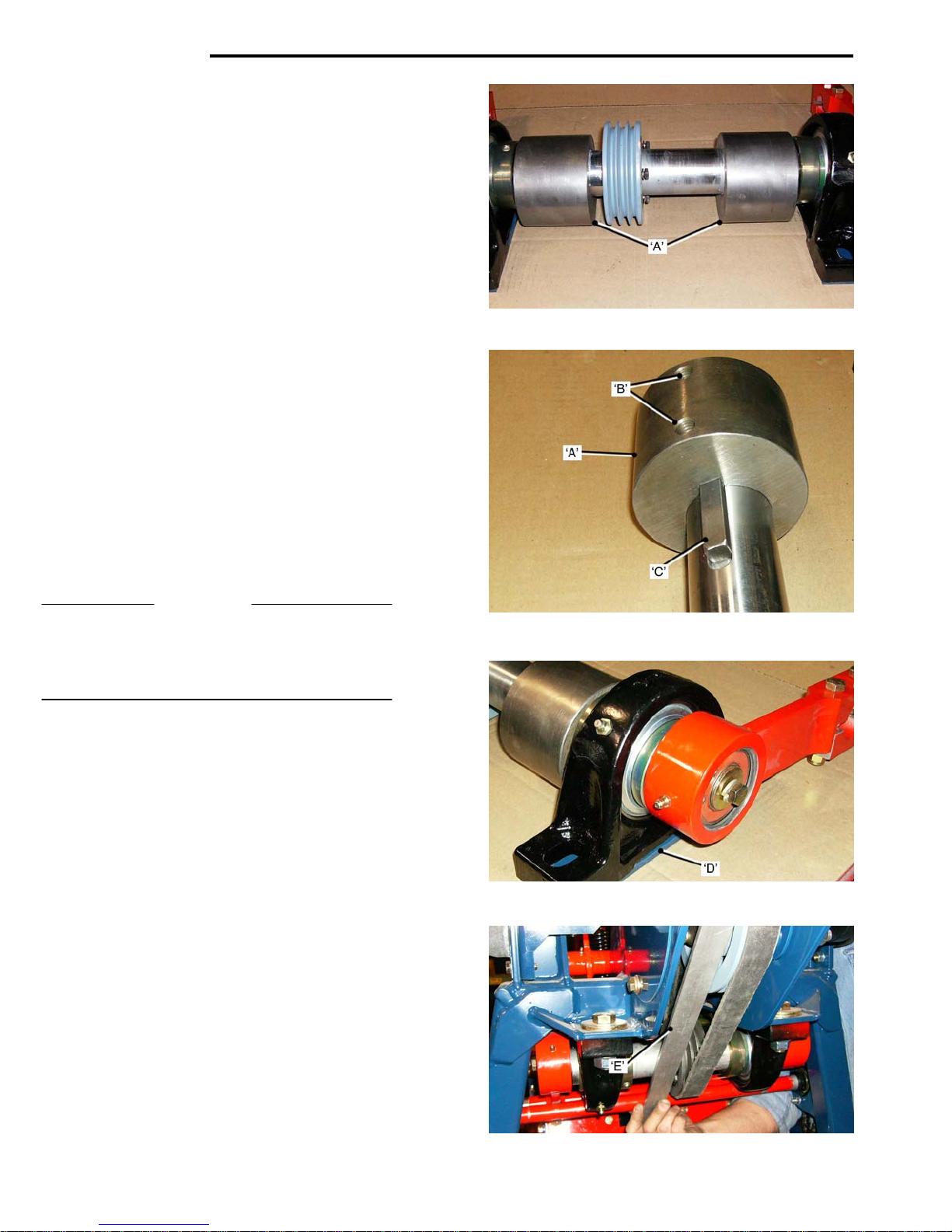
MAINTENANCE
Crank-Shaft Assembly - 24 inch Machine.
The Crank-Shaft on 24 inch machines has two
Counter Balance Weights ‘A’. They are
Shaft and locked with Set Screws.
It is necessary to remove one of the Weights if the
Driven Sheave needs to be removed.
To remove the Counter Balance Weight:
• Remove the
page 4-8.
• Remove a
See page 4-8.
• Remove a
See page 4-9.
• Bac
• Remove the
On re-assembly the Counter Balance Weight should
be located against the Bearing Lock-Collar.
IMPORTANT
When installing the 24 inch Crank-Shaft Assembly
into the frame, the Shim Plates ‘D’ m
between the Bearing Flange and the Frame to
allow the Counterweights to clear the Frame.
.
Installing Crankshaft Assembly.
• Fit a new Drive Belt over the Drive Moto
• Carefully rai
• Fit the Drive Belt, with ‘slack’, onto the
• With a ‘Straig
• Adjust Drive Belt tension as shown on page 4-7
4-10
k-off the Set Screws ‘B’, and slide the
Weight off the Shaft. Remove the Key ‘C’.
Sheave.
position and bolt it into place.
shaft Sheave
and Drive Motor Sheaves, then tighten the Bolts
in the Crankshaft Sheave Taper Lock Bushing.
.
Crank-Shaft Assembly, see
Connecting Rod.
Crank-Shaft Bearing.
Driven Sheave. See page 4-9.
se the Crankshaft Assembly into
ht Edge’ ‘E’, align the Crankshaft
Keyed to the
ust be fitted
r
Crank-
Page 57
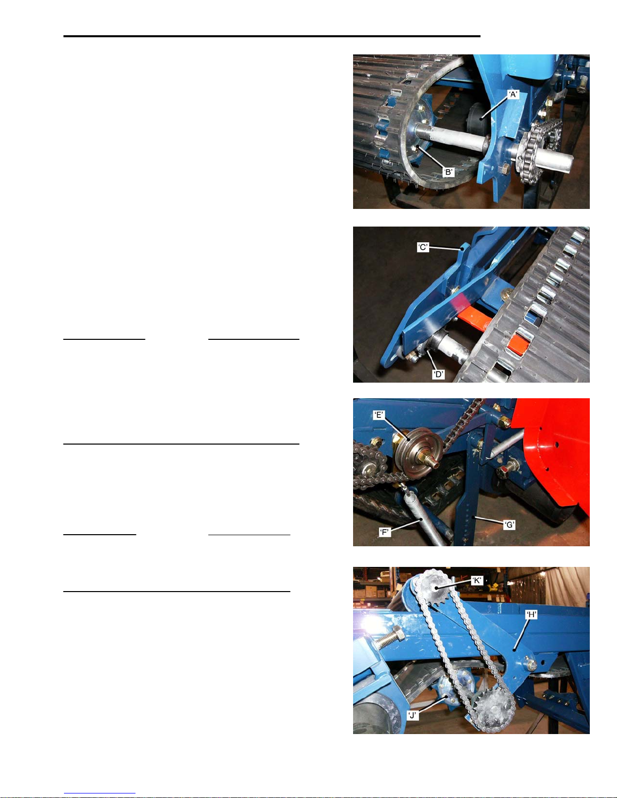
MAINTENANCE
Main Conveyor Mat
The Rubber Conveyor Mat was initially used in areas
with abrasive soil conditions, but has proven to work
well in a variety of conditions. It is the preferred
choice of most Sod Growers. See page 4-12 for the
installation of a new Mat and Metal Clip replacement.
Conveyor Mat Drive
A Hydraulic Motor ‘A’ drives Sprocket
‘slots’ in the mat.
The ‘slots’ are fitted with replaceable Metal Clips.
See following pages for Clip replacement.
To prevent premature/excessive wear, the Sprocket
Teeth must b
See following pages for alignment procedure.
Crown Roller
A Crown Roller, at the front of the Conveyor, keeps
The Mat ‘tracking’ square to the conveyor frame.
The Roller is aligned in the frame with adjustable
Tapered Wedges ‘C’ locat
Bearing ‘D’.
See following pages for alignment procedure.
IMPORTANT
The Crown Roller Must be set so that the Sod Guide
Bracket does not ‘foul’ against the Conveyor Mat
during operation.
Initially set the Crown Roller at the mid-point of adjustment, determined by the back stroke of the Cutter
Blade, and with allowance for the thickness of the
Conveyor Mat. Also allow for so
of the assembly during final alignment.
Mat Tension Idler.
Tension on the Conveyor Mat is maintained
by adjustable Tensioned Idlers ‘E’.
The Tension Springs ‘F
holes in the Idler Arm ‘G
IMPORTANT
Do not allow the Idler Arm to approach an angle of
90 degrees relative to the Conveyor Frame.
If this occurs the Idler Arm will be pulled ‘over center’
and tension in the Conveyor Mat will be lost.
Mat Support. 4 inch Roller Drive.
The Mid-Idler Shaft and Sprockets Assembly ‘H’, sup-
ports the Conveyor Mat below the Conveyor Frame.
Sprockets ‘J’
Roller ‘K’.
e ‘centered’ in the ‘slots’.
ed at each Roller Shaft
’ can be adjusted in a series of
’.
on the Idler Shaft drive the 4 inch Feed
s ‘B’ that run in
me forward movement
4-11
Page 58
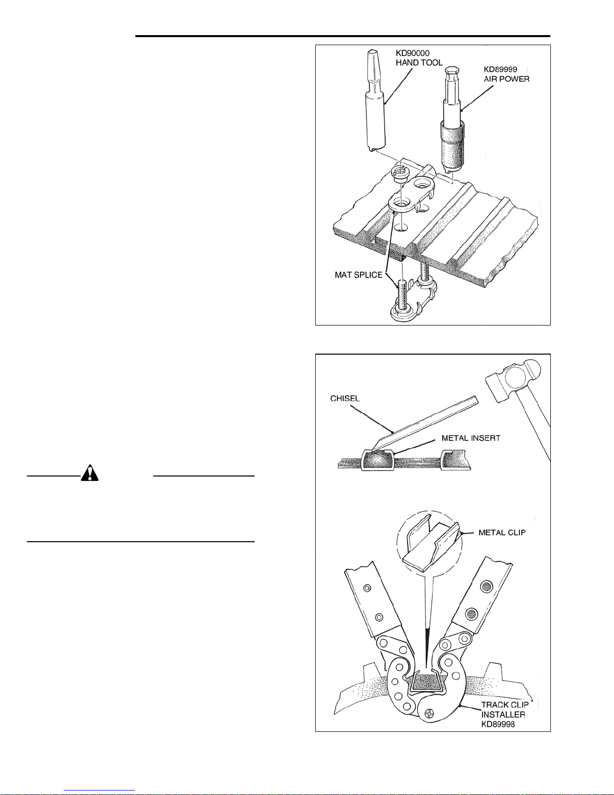
MAINTENANCE
Rubber Conveyor Mat.
Mat Splices.
The Conveyor Mat is joined with Metal Splices.
The Mat must be joined with the lower part of the
Mat over-lapping the upper part. It is important that
any excess portion of the Threaded Stud is broken
off above the Nut when the Splice has been installed.
Special Tools are available for easy removal and
installation of the Mat Splices.
Type ‘A’ is
Type ‘B’ is fo
MAT SPLICE INSTALL
Mat Clips.
The Metal Mat Clips will wear and need replacing.
Use a chisel or similar tool to open them up for removal.
A Special Tool (Part No. KD89998) is available to make
installation fast and safe.
WARNING
Do not operate the Conveyor unless the
Stud Ends have been broken off.
Failure to observe this precaution may result
in serious injury to the operator, and/or damage to
the machine.
MAT CLIP REMOVE/INSTALL
4-12
for use with Air Power.
r use with a hand tool.
ATION
Page 59
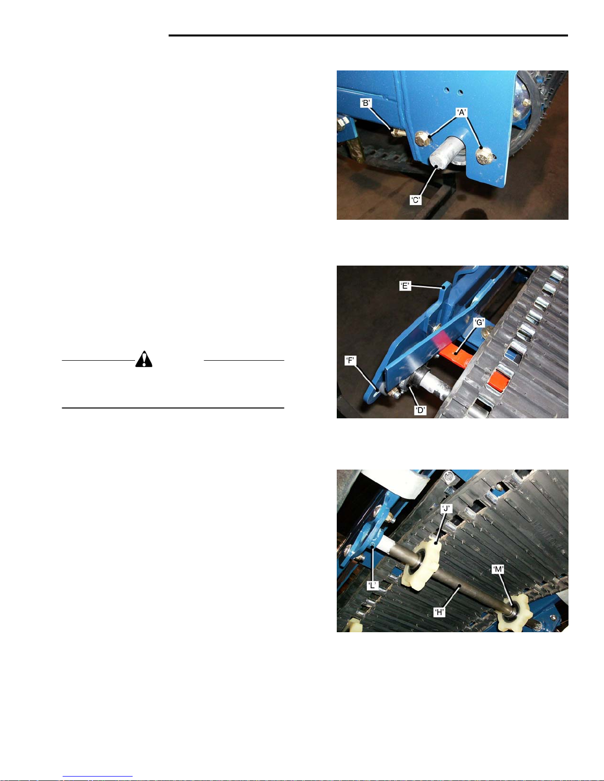
MAINTENANCE
Conveyor Mat Installation.
When the Conveyor Mat has been installed into the
Frame and onto the Sprockets, and has been ‘joined’
with Mat Splices, it will be necessary to align the Mat
so that it runs ‘parallel’ in the Frame.
The Mat is kept in alignment by the Driving Sprockets
at the top of the Conveyor,
the front bottom of the Conveyor.
Drive Sprocket Shaft Alignment.
• Tighten the S
the right hand side of the Conveyor.
• Loo
Crown Roller Alignment.
• Loosen the Bearing Bolts ’D’ and the Adjust-
Adjustments must be don
One person to operate the controls and the other to
make the adjustments.
• Run the
• Observe if the mat tracks t
• I
frame), tap the ‘left side’ Adjusting Wedge
• Adjust until the Mat run
• Stop the Con
• Tighten all fa
• Set the Roller Sc
Idler Sprocket Shafts.
Two Idler Sprocket Shafts ‘H’, are lo
of the Crown Roller,(rear-most one shown).
The Sprockets ‘J’, on the Idler Shaft mu
run centrally in the Mat Slots.
• Install the Sprockets ‘J’ lo
• Fit the Shafts and Beari
• Position the
• Tighten Set Scre
4-13
sen the left hand side Bearing Bolts ‘A’.
Screw the Adjusting Bolt ‘B,’ ‘
Shaft ‘C ’is at 90 degree
Tighten the Adjusting Bolt and the Lock-nut.
ing Wedges ‘E’. Tap the Wedge
position the Crown Roller Shaft in the center
of the Adjusting Slots ‘F
the frame). Do not fully tighten the fasteners,
to allow for final alignment adjustment.
CAUTION
Conveyor at LOW SPEED.
side of the frame), tap the ‘right side’
ing Wedge ‘do
f the mat tracks to the ‘right’ (outer side of the
‘down’.
the Roller.
lock into place with Set Screws ‘L
center of the Mat Slots.
and the Crown Roller at
haft Bearing mounting bolts, at
IN’ until the
s to the Frame.
s ‘down’ to
’. ( on both sides of
e by two people.
o the ‘left’ (inner
Adjust-
wn’.
s parallel to the frame.
veyor.
steners.
raper ‘G’ to 1/32 in from
cated to the rear
st be adjusted to
osely onto Shafts ’H’.
ngs into the frame and
’.
Sprockets with the’ teeth’ in the
ws ‘M, in the Sprocket Bearings.
Page 60
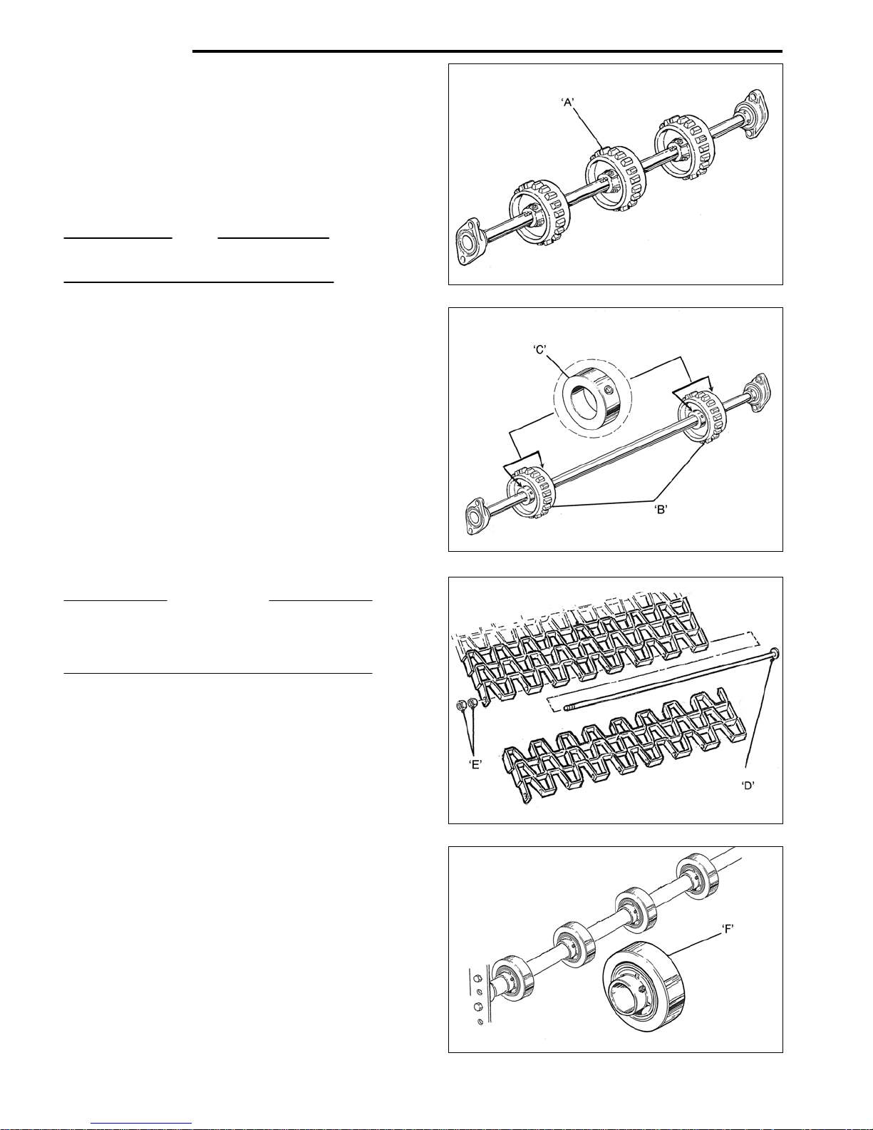
MAINTENANCE
Mintex Metal Mat
There are no replacement parts in the Mintex Mat.
Replace it as an assembly.
To ensure a long service life, it is important that the
Mat Drive Shaft, Idler Shafts, Idler Sprockets and
Rollers Assemblies are parallel to each other and
correctly set ‘square’ in the Frame.
NOTE
The links, at the outer edge of the Mat must
point ‘opposite’ to the direction of mat travel.
Drive Sprockets.
• The teeth of the Drive Sp
contact the Mat Connectors.
The Drive Sprockets are keyed to the Drive
Shaft and locked with Set Screws.
Mid-Idler Sprockets.
• The Mid-Idl
Shaft and held in place with Lock Collars ‘C’.
They are ‘pushed’ by the fixed Mat Connectors.
Set the Idler Sprockets one inch closer to the
Center of the Mat than the Drive Sprockets.
• Spro
openings. If the Teeth contact the side face of
the Links it will result in excessive and premature wear to the Sprockets and the Mat, and
early failure of the Mat.
IMPORTANT
Replace the Sprocket Teeth when they become
Worn. Worn teeth can cause serious damage to
the Mat.
Mintex Mat. Adjust Length
• The Mintex M
To prevent it from ‘jumping’ over the Sprocket
Teeth it can be shortened by re-positioning
the removable Mat Connector ‘D’.
The Mat Connector is secured with two nuts ’E’.
The two lower Idler Shaft Assemblies have ‘Rubber and
Steel’ Rollers ‘F
Set Screws hold the Bearings
The Front Lower Idler Shaft has four Sprockets.
The outer Sprockets are keyed to the Shaft and locked
with Set Screws. See ‘A’ a
The two inner Sprockets rotate freely on the Shaft and
are held in place with Lock Collars. See ‘B’ above.
The Front Lower Idler Shaft is aligned with Adjusting
Wedges. The adjustment procedure is the same as that
on the Rubber Mat. See page 4-13.
4-14
er Sprockets ‘B’ rotate freely on the
cket Teeth must be centered in the Mat
at will ‘stretch’ during use.
’ that run on Sealed Bearings.
bove.
rockets ‘A’ must
in place on the Shaft.
Page 61
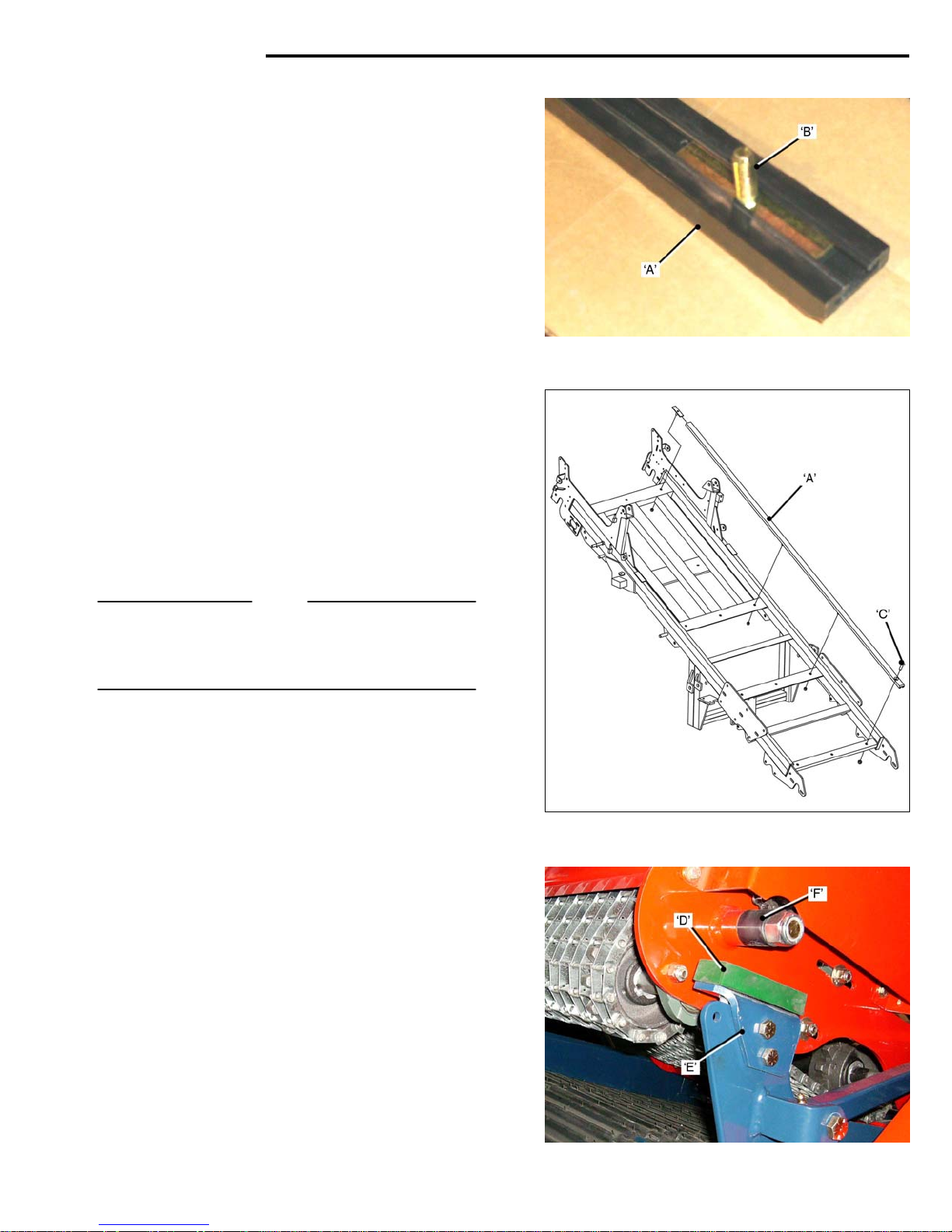
MAINTENANCE
Conveyor Mat Sliders. Rubber Mat.
The Conveyor Sliders ‘A’ ar
ethylene that does not require lubrication. Their service
life will vary, depending up on the soil conditions.
At each major service check the Sliders for excessive
wear, particularly under the Roll-up Tray.
Each Slider is held in place with three T-Bolts ‘B’ and,
at the bottom end, a Flat-head Socket Cap Screw ‘C’.
Excessive wear will be evident when the T-Bolts
through the Slider.
The wear thickness, (3/8 inch), is le
all thickness.
Remove/Replace Slides.
• Rele
• Remove the four Lock-nuts that hold the Slider
When installing new Sliders, allowance must be made
for expansion and contraction due to temperature
changes. Do not fully tighten the T-Bolts, they should
be ‘snug’ tight. To prevent damage to the Sliders the
Flat-head Screws must not be tightened too much.
NOTE
It is recommended that if one slider is worn, both should
be replaced.
The 24 inch machine has three Sliders. To prevent the
possibility of ‘tapered’ Rolls, replace all three.
Roll-up Conveyor Stops.
The Roll-up Conveyor is a Mintex Metal one. See page
4-14 for details on the Mintex Mat.
• Roll-up Conv
• Bus
• Repl
ase the tension on the Mat Idlers.
(See page 4-11), to allow the Mat to be raised
up to provide access to the Sliders and Lock-nuts.
in place and remove it from the Frame.
Brackets ‘E’, on both si
hings ‘F’ are attached to both sides of the
Roll-up Frame.
ace the Conveyor Stops and Bushings if
badly worn or damaged.
e made from UHMW Poly-
show
ss than the over-
eyor Stops ‘D’, are attached to
des of the Frame.
4-15
Page 62

This page left blank.
4-16
Page 63
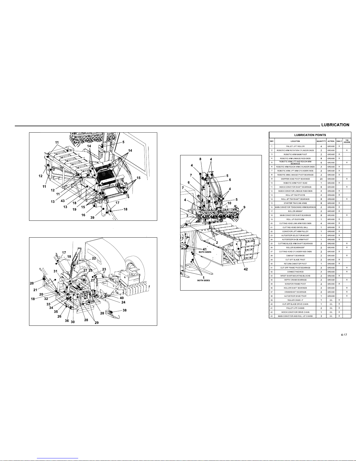
Page 64

Page 65

ADJUSTMENTS
SECTION 5
Adjustments.
Cut-Off Length 5-1
Cut-Off Sprocket Selection Chart 5-2
Cut-Off Cam, Return Cam, Return Cam Stop 5-2
Return Cam Stops Selection Chart 5-3
Index Conveyor 5-3
Roll End Sensor. Sensor Flag Setting 5-4
Cut-Off Blade Depth Adjustment 5-4
Spring Cam Eccentric Setting 5-4
Cut-Off Blade 5-5
Pitch Angle. Pitch Adjustment 5-5/5-6
Ground Roller. Scraper. Sod Guides 5-6
Roll-Up Conveyor. Roll-Up Sprockets 5-7
Roll Flap Stabilizer 5-7
Main Conveyor Alignment 5-8
Cutter Head Alignment 5-8
Pallet Lift Forks Sensors 5-9
Page 66

Page 67
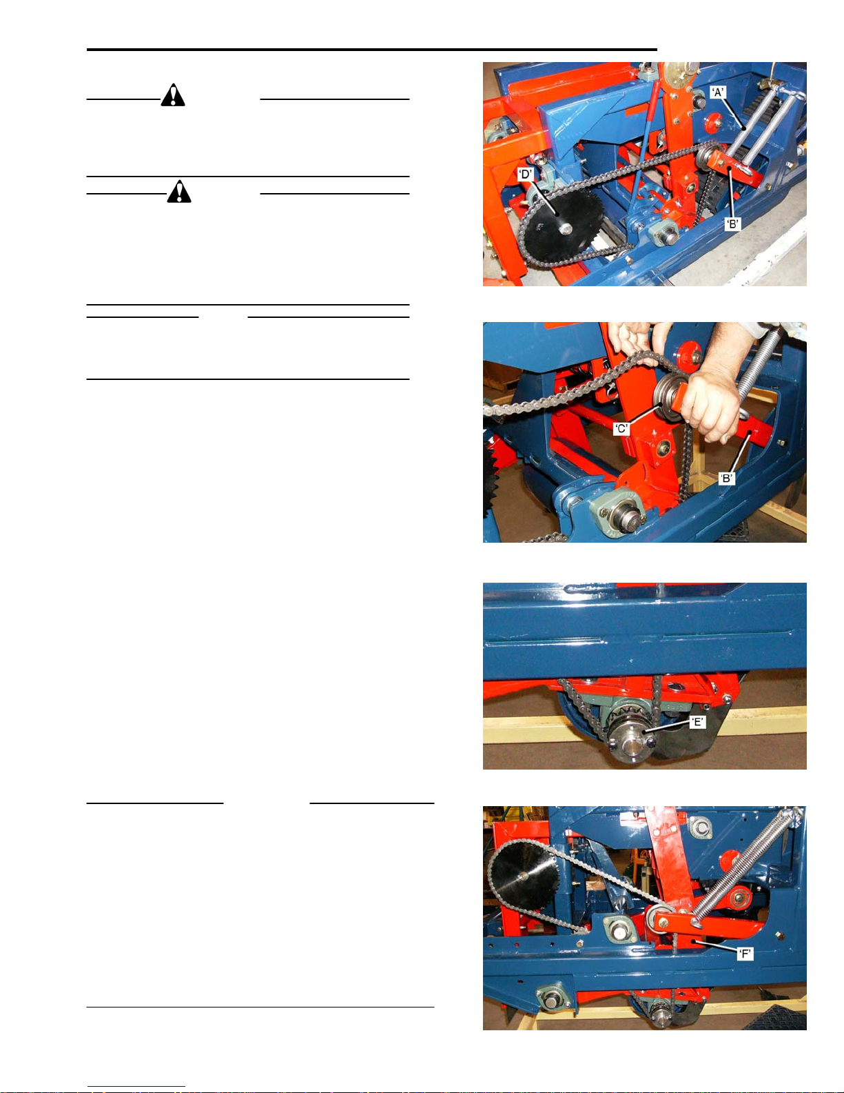
ADJUSTMENTS
Cut-Off Length Adjustment.
WARNING
The Safety Lift Lock MUST be in place when
working on the Cutter Head in the raised position.
Failure to observe this warning could result in
Serious injury or death.
CAUTION
When changing Sprockets, to modify the Cut-Off length,
the length of the chain may also have to be changed,
particularly when changing from ‘large’ to ‘small, or ‘small
to ‘large’
Incorrect chain length can result in the Idler Arm hitting
the frame causing damage to the Cut-Off Cam.
NOTE
The ‘standard’ Cut-Off leng
Rolls that are more than 10 inches in diameter will not
fit on the Index Conveyor.
Refer to the Sprocket Selection Chart on the following
page for available Sprocket Combinations.
To change Sprockets:
• Set the Depth
The Idler Arm Tension Springs ‘A’ will be
‘light’ tension.
• Carefully pre
lift the Chain off the Idler Pulley ‘C’.
• Remove the
• Bac
(early units have Taper Lock Bushings), and
remove it from the Cam Shaft.
If the sprocket combinations chosen make it necessa ry
to change the Roller Sprocket:
• Remove the
• Install the ne
• To ensure that the Chain ‘
When making changes from ‘large’ Sprockets to ‘sm
or ‘small’ to ‘large’, it may be necessary to adjust the
length of the chain, adding/subtra
When fitting the Roller Sprocket, che
far enough onto the Roller Shaft to ensure that the Taper
Lock Bushing Bolts do not hit against the frame.
Before operating the machine, it is important to check
that there is a minimum 1 ½ inches clearance between
the Idler Arm and the Frame ‘F
Cylinder fully extended.
k-off the Set Screw in the Cam Sprocket,
Taper Lock Bushing ‘E’. Fit the bolts
threaded holes and tighten them to release the
Taper Lock.
reverse order to above.
Sprockets and Idler Pulley, visually check that
they are in alignment.
IMPORTANT
th is 54 inches.
of Cut Cylinder fully retracted.
under
ss down on the Idler Arm ‘B’, and
Chain from the Cam Sprocket ‘D’.
Bolts from the Roller Sprocket
into the
w Sprockets and refit the chain in the
runs straight’ on the
all’,
cting Links as required.
ck that it is pushed
’, with the Depth of Cut
5-01
Page 68
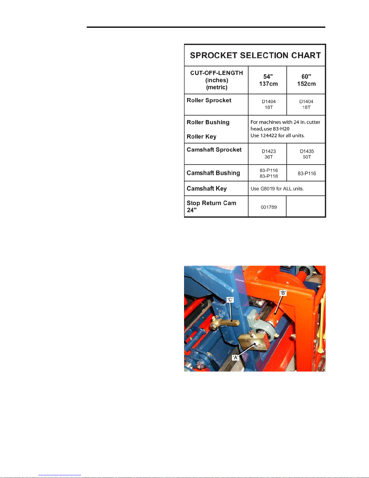
ADJUSTMENTS
Cut-Off Length.
Sprocket Selection Chart.
The Sprocket Combinations that are recommended,
for various lengths of sod, are approximations.
The final choice of Sprockets will best be determined
by ‘field trial’.
In the spring, when sod tends to be ‘wet’, it ‘stretches’
as it is cut. In drier conditions the cut length tends to
be closer to the ground cut-off length.
The type of grass, age of the so
will also affect the length of the sod after it is cut.
Cut–Off Cam. Return Cam and Return Cam Stop.
As the sod ‘length’ is cut to before the Cutting Blade has
completed its cut under the full length, a Return Cam ‘A’,
fitted on the ‘outer’ end of the Cut-Off Camshaft ‘B’, and
Return Cam Stop ‘C’, fitte
form cut length of the first piece of sod.
When the Return Cam ‘A’
it is engaged by the Return Cam Stop ‘C’. This indicates
the end of the cut, and prevents the spring pressure on
the Cut-Off Frame from rotating the Cut-Off Camshaft
‘backwards’.
5-02
d, and the type of soil
d on the Frame, ensure a uni-
reaches the correct position,
Page 69
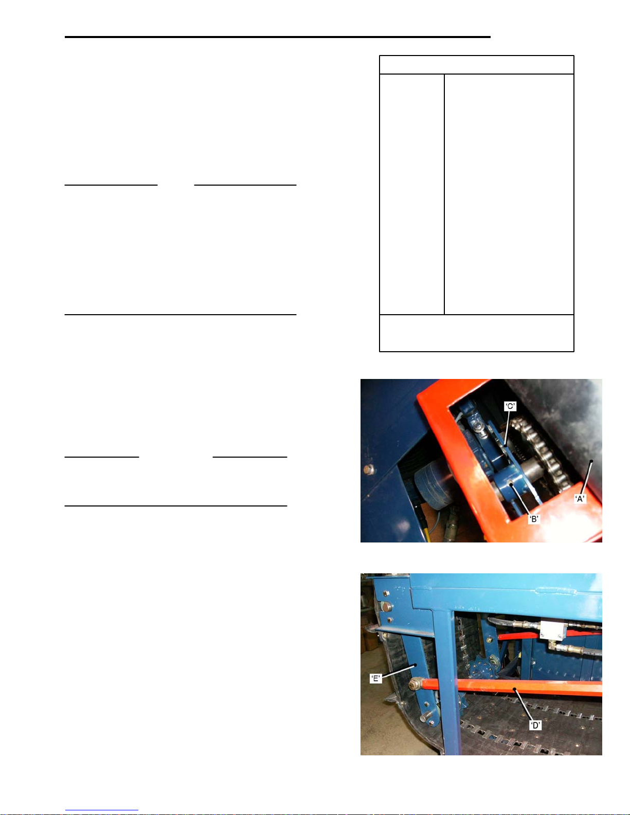
ADJUSTMENTS
Return Cam Stop. Return Cam Stops.
A different Return Cam Stop is required for each length Part No. Cut Length.(inches).
of cut.
The identifying Part Number is stamped into each one. 001794 18.0
Refer to the chart for the Part Numbers. 0017
0017
001791 40.5
Cut-Off Cams. 0166
0017
NOTE 0166
There are three Cut-Off Cams available: 0146
0017
Slow Lift – For Cut lengths
Stamped with the letter
0017
Fast Lift – For Cut lengths
Stamped with the letter ‘F’
‘Standard’
Super Lift – For len
Stamped with the letters
NOTE: * - Ind
Index Conveyor. dependin
The fore and aft position of the Index Conveyor Roll
‘Cleats’, relative to the Main Conveyor, is adjustable.
This determines the location of the Roll Cleats, and
ensures that the Rolls drop onto the Inde
‘between’ the Roll Cl
Adjustment is made by repositioning the Sensor Flag
relative to the Sensor.
IMPORTANT
When adjusting the Sensor Flag:
Start with it ‘centered’ on the Sens
small increments to obtain the correct setting.
To adjust the Conveyor position:
• Pull back the Rub
• Loosen Set Screw ‘B’, in the Sensor Flag Boss.
• Rotate the Se
the Conveyor Cleats ‘forwards’.
• Rotate the Sensor Flag ‘counterclockwise’ to
move the Conveyor Cleats ‘rear
Index Conveyor Mat – Tension.
Tension is maintained on the Conveyor Mat by the Side
Link Arms ‘D’.
As the Index Conveyor goes from its normal operating
position to the ‘eject’ position, the Link Arms ‘D’ ‘push’
back against the Idler Tension Arms ‘E’
out of the Conveyor Mat.
To increase the Mat tension:
• Loo
• Turn the Li
• They must b
• Re-tig
sen the Locknuts ‘F’ at each end of the Arms.
Shaft parallel to the Conveyor Drive Shaft.
gths greater than 72 inches. 015553 90.0
nk Arms ‘clockwise’ to extend them.
hten the Lock-nuts. 5-03
under 54 inches. 001802 64.6
‘S’. 001801 68.9
54 inches to 72 inches. 001799 77.6
. This is the 001376 *80.0/81.0
Cam for Robomax. 001800 85.8
‘FF’. 014974 *96.9/98.0
x Conveyor
eats.
or, then rotate it in
ber Cover ‘A’.
nsor Flag ‘C’ ‘clockwise’ to move
wards’.
, taking the slack
e adjusted equally, to keep the Idler
93 24.0
92 36.0
19 45.0
90 *48.0/48.4
18 51.6
45 54.0
88 60.0
87 *72.0/72.8
icates length change
g on the Sprockets Fitted.
Page 70
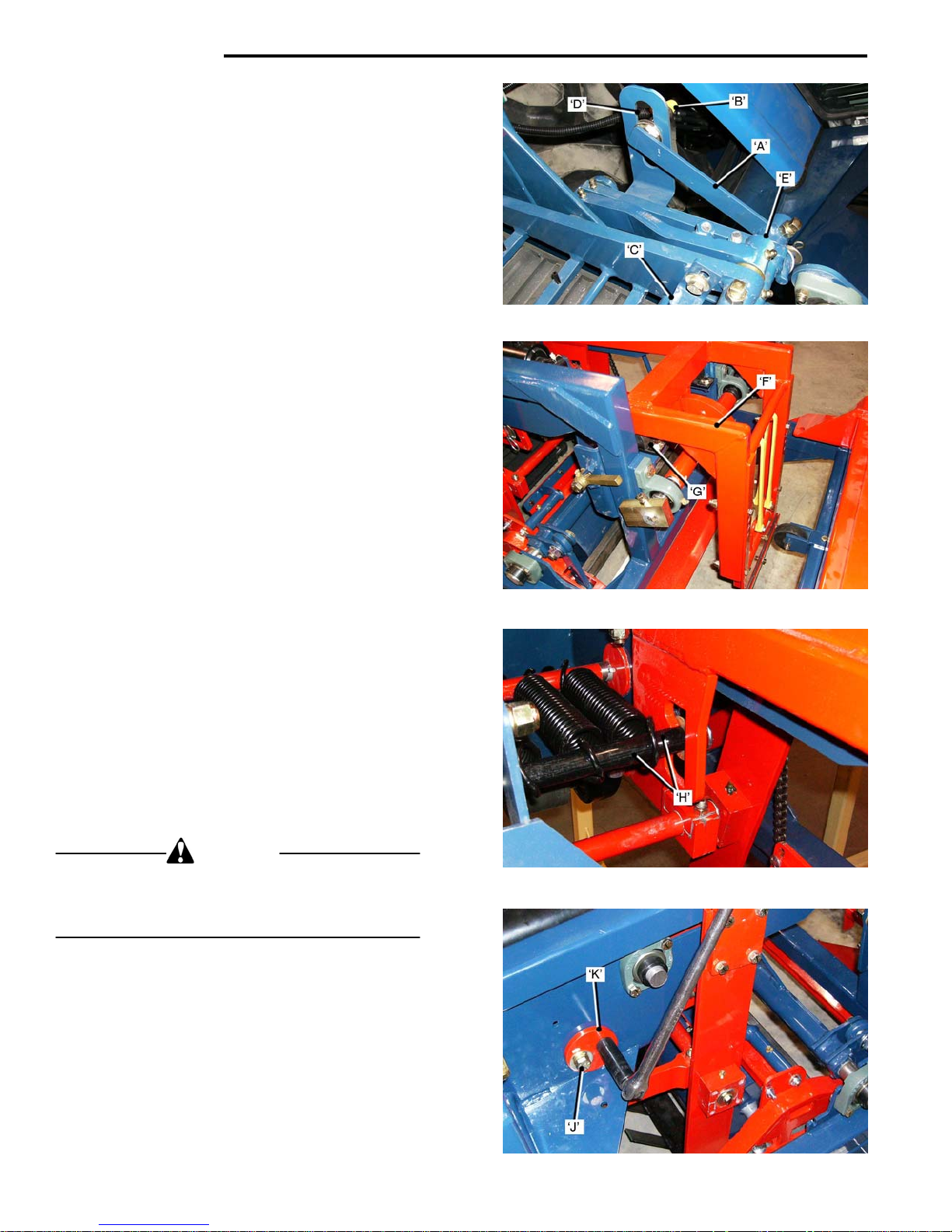
ADJUSTMENTS
Roll End Sensor.
The Roll End sequence starts with the Sensor Flag ‘A’
directly in line with the Sensor ‘B’, before the leadin
edge of the sod has reached the Starter Gate ‘C’.
The Roll End Sensor LED on the Cab Control Panel
will indicate ‘ON’.
As the Sod passes into the Starter Gate ‘C’ the Sen
‘Flag’ will rotate away from the Sensor ‘B’ and the LED
will indicate ‘OFF’.
The LED will continue to indicate ‘OF
edge of the sod has passed the Starter Gate. At this
point the Sensor Flag will rotate ‘back’, to be in line with
the Sensor, and the LED will indicate ‘ON’.
Sensor and Sensor ‘Flag’ Setting.
• Position the
‘D’. Do not ful
• Loo
• Loo
Cut-Off Blade, Depth Adjustment.
The Cut-Off Blade must be kept sharp. The Depth of Cut
should be just deep enough to ensure a clean cut.
The Cut-Off Frame ’F’ should make only ‘light’ contact
with the Rubber Stops ‘G
The Spring Shaft ‘H’ is located in the ce
the factory, normally this pro
Moving the Spring Shaft to the ‘upper’ position re
the spring pressure.
Moving the Spring Shaft to the ‘lo
the spring pressure.
To change the Spring Shaft Setting:
WARNING
Exercise care when releasing the Spring Cam. Use a
Ratchet with a long handle. This will allow the Spring
Cam to turn past center. Failure to observe this warning
could result in personal injury.
To release the Spring Tension:
• Loo
• Turn the Sp
• Move the Spring Shaft to the de
• Re
• Tighten the L
5-04
sen the Set Screw ‘E’, position the Sensor
Flag directly in line with the face of the Sensor
and re-tighten the Set Screw.
sen the Locknuts on the Sensor Body.
Adjust the Locknuts until the face of the Sensor
is 1 to 3mm from the Sensor ‘Flag’. Tighten the
Locknuts.
sen the Lock-bolts ‘J’.
set the Spring Tension by turning the Spring
Cam Eccentric ‘counterclockwi
over-center..
Sensor ‘B’ in the center of the Slot
ly tighten the Locknuts.
’.
vides correct spring pressure.
ring Cams Eccentric ‘K’ ‘clockwise’.
ock-bolts ‘J’.
F’ until the trailing
nter position at
wer’ position increases
sired position.
se’ until it ‘clicks’
g
sor
duces
Page 71
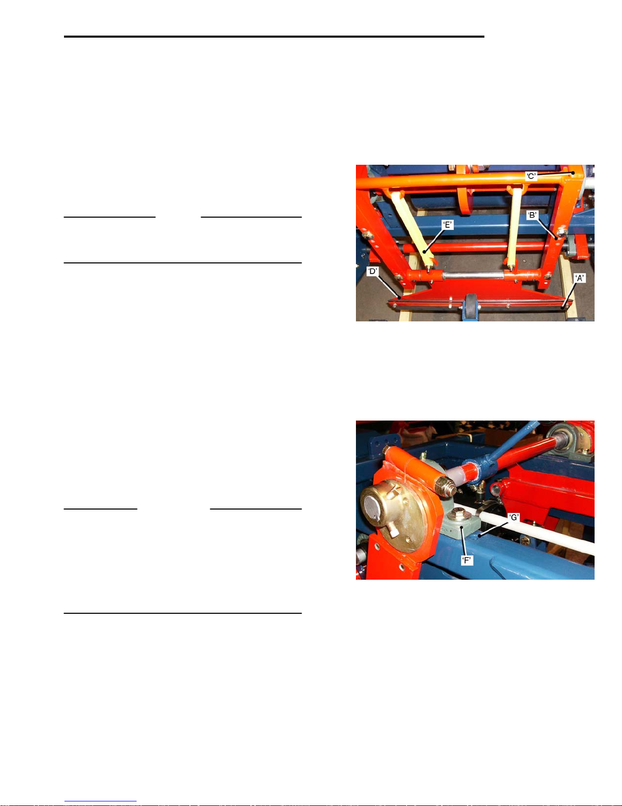
ADJUSTMENTS
Cut-Off Blade
If the Cut-Off Blade ‘A’ do
the sod when the Spring Shaft is in the desired location,
reposition the Cut-Off Blade Frame ‘B’ o
on the Cut-Off Frame ‘C’.
The Cut-Off Blade depth is reduced over time by wear,
and by sharpening. If a blade is less than 2 ½ inches in
depth, it must be replaced.
Check that the edge of the Cut-Off Blade Mount ‘D’ do
not hit the sod, on the ‘down’ stroke, as this will damage
the sod and cause problems when the sod is ‘laid’.
NOTE
A Serrated Blade is available for use in soft soil, or
excessive thatch. This Blade will give a cleaner more
positive cut.
The Urethane Tension Straps ‘E’, allow the Blade to
‘swing’ with the forward travel of the machine as the
cut is made. When the machine is stationary the Blade
should hang in the vertical position. Any Change to the
shape, or position, of the Tension Straps attaching hooks,
will change the angle of the blade.
Pitch Angle
Pitch Angle is the angle that the Cutter Blade makes
relative to the ground. The Pitch Angle is set at the
factory for average cutting conditions.
Pitch Angle can be adjusted to improve cutting performance in soft or hard soils.
In soft conditions the Pitch Angle should be set so that
the Cutting Blade is almost ‘parallel’ to the ground.
In hard soil the Blade Angle should be increased, this
maintains the correct cutting angle, and also prevents
the Cutting Head from coming out of the ground.
IMPORTANT
When the Pitch Angle is changed, the relationship
of the Cutting Blade to the Conveyor Mat, and also
the Ground Roller, must be maintained.
The Front Idler Shaft of the Conveyor Mat can be
adjusted to ensure that there is no interference between the Mat and the Blade.
Refer to the Ground Roller adjustment instructions
for the correct Roller to Blade set-up.
Pitch Adjustment.
At the factory the Bearings ‘F
set of holes in the frame, this is the ‘nor
• Move the bea
mum pitch), for hard soil.
• Or, move the beari
mum pitch) for soft soil.
For ‘fine adjustment’ of the Blade Pitch, see page 5-6.
es not cut ‘completely’ through
’ are located in the ‘center’
rings to the front holes ‘G’, (maxi-
ngs to the rear holes, (mini-
ne hole lower
es
mal’ setting.
5-05
Page 72
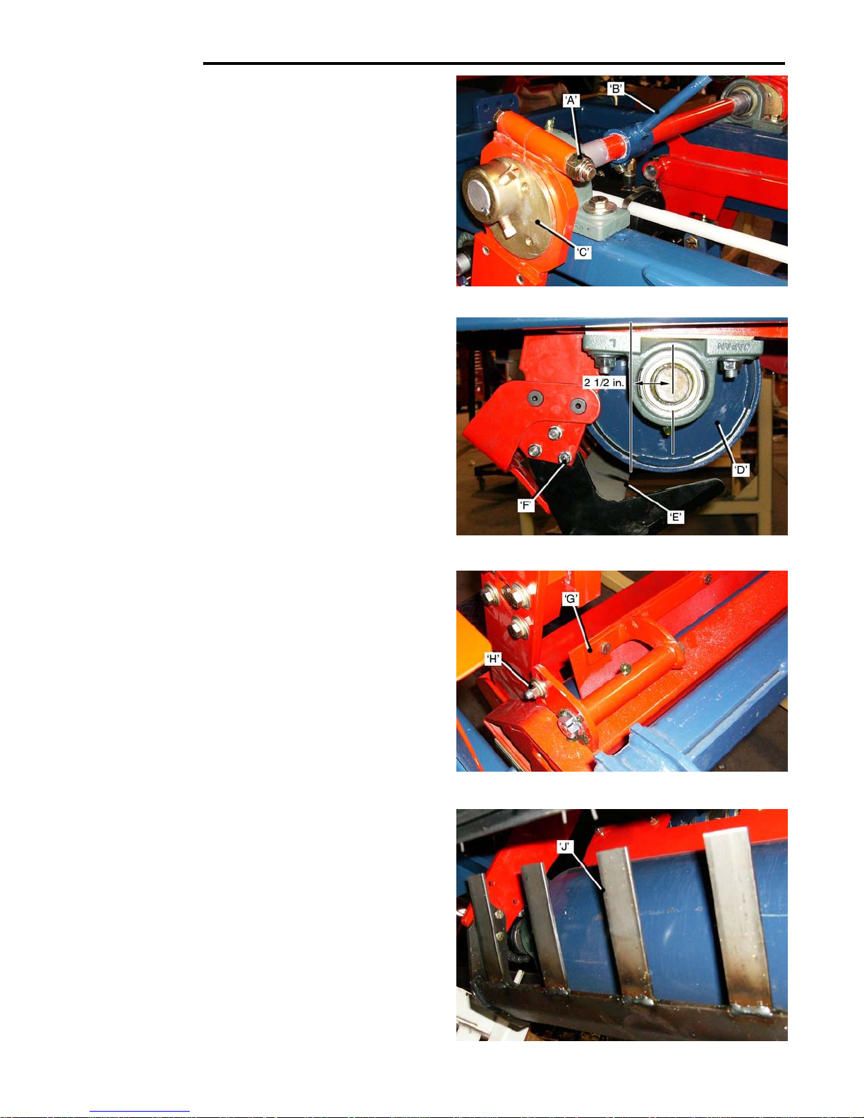
ADJUSTMENTS
Pitch Angle – Fine Adjustment.
On the left and right hand sides:
• Loo
• Turn the Adju
• Re-tig
Roller Adjustment.
The Ground Roller ‘D’ supports
Conveyor. It also applies pressure to the sod ahead
of the Cutter Blade ‘E’.
The Roller position can be adjusted ’forward’ or ‘back’
on the Cutter Head Frame, it must be positioned with
the vertical centerline of the Roller is 2 ½ inches ahead
of the Cutter Blade, when the Blade is at its maximum
forward stroke.
The Roller and Blade must be parallel to each other,
avoid ‘tapered’ rolls.
The Roller must be ‘centered’ between the Cutter Side
Arms, to prevent the attaching bolts ‘F
the Roller.
In ‘Peat’ or ‘Muck’ soil conditions the 2 ½ inch dimension,
from Roller Center to Blade, may need to be reduced to
maintain the proper cutting action.
In ‘soft soils’ or ‘excessive thatch’, ‘rolling’ the area to
cut, before harvesting, will result in easier cutting and a
better quality, tighter roll.
In ‘stoney ground’ conditions it is advisable to move the
Roller ‘forward’, to allow small stones to pass between
the Blade and the Roller.The increase in clearance can
be up to 2 or 2 ¼ inches. Insufficient clearance from Roller
to Blade, causes a ‘pinching action’, resulting in pieces of
sod that are longer than required
Ground Roller Scraper.
The cut length of the sod is measured by the rotation of
the Ground Roller ‘D’. Th
The build-up of grass, mud or dirt, on the Roller, can
increase its diameter, resulting in an increase to the
length of cut.
The Roller Scraper ‘G
is provided by ‘slotted’ holes. Loosen the fasteners ‘H’
and pivot the Scraper until it is ‘just’ clear, (1/32in.), of
the face of the Roller.
Sod Guides.
The Sod Guide ‘fingers’ ‘J’
Blade to the Conveyor. Check that they line-u
Conveyor Mat, and do not hit against it when operating.
If any Fingers that get ‘bent’ must be straightened before
operating the machine.
5-06
sen the Eccentrics Clamps Locknuts ‘A’.
stment Handle ‘B’ to rotate the
Eccentric Adjusters ‘C’ to obtain the required
amount of pitch angle.
hten the Locknuts.
the front of the Harvester
’ from fouling against
be
e Roller must be kept clean.
’ prevents this build-up. Adjustment
direct the sod from the Cutter
p with the
to
Page 73
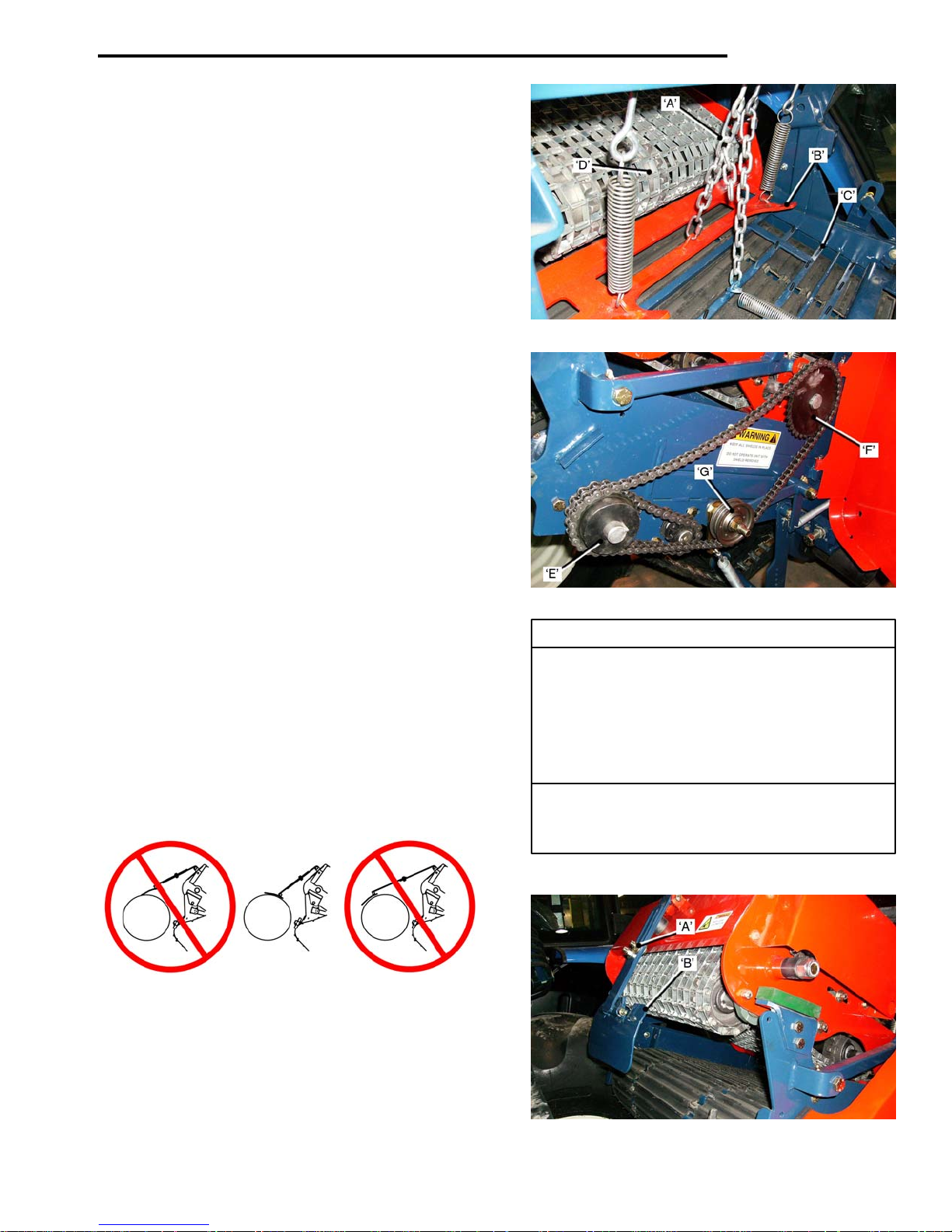
ADJUSTMENTS
Roll-Up Conveyor.
The Roll-Up Tray Hanger Chain ‘A’, sh
that the clearance between the Roll-Up
the Starter Tray ‘C’, is no less th
Roll-Up Sprockets.
The Roll-Up Conveyor ‘D’
sod has passed the Starter Tray. The speed of the RollUp is determined by the Sprocket Combinations fitted at
the factory. The factory settings are for average operating
speed, for a specified cut length of sod.
The Roll-Up is chain driven by Sprocket ‘E’
Conveyor Sprocket Shaft, to Roll-Up
Chain tension is controlled by the Idler Pulley ‘G
Sprockets can be changed to suit operator requirements.
Refer to the Sprocket Chart for alternate Sprockets.
The Mat Front Idler Assembly must be set so that Mat is
‘just clear’ of the front cross-member. This
sod from getting ‘jammed’ and disrupting the operation.
The Rear Idler Assembly adjusts the ‘upper’ Mintex Mat
to allow enough slack, so that the mat can be pressed
down 1 ½ inches, between the front and rear sprockets. Roll-Up Dri
16 inch Mac
When adjusting the shafts to tension the mats, the front Drive Sprocket 23T. (Supply 19T & 27T)
and rear shafts must be parallel, to prevent ‘coni
24 inch
Drive Sprocket 16T. (Supply 12T).
Driven Sprocket 36T.
Roll Flap Stabilizer.
The Roll Flap Stabilizer ‘H’, mus
is positioned on the sod roll as shown below. Drive Sprocket 12T.
Driven Sprocket 24T.
Adjust as follows:
• Loo
• Slide the Roll
sen the Locknuts ‘J’.
match the size of the rolls.
Tighten the Locknuts.
completes the roll-up after the
Flap Stabilizer ‘up’ or ‘down’ to
ould be set so
Tray ‘B’, and
an 2 to 2 ½ inches.
on the Main
Drive Sprocket ‘F’.
’.
prevents the
Roll-up Sprockets.
ve.
hine.
cal’ rolls. Driven Sprocket 33T. (Supply 36T)
Machine.
t be adjusted so that it Vertical Drive Sprockets.
5-07
Page 74
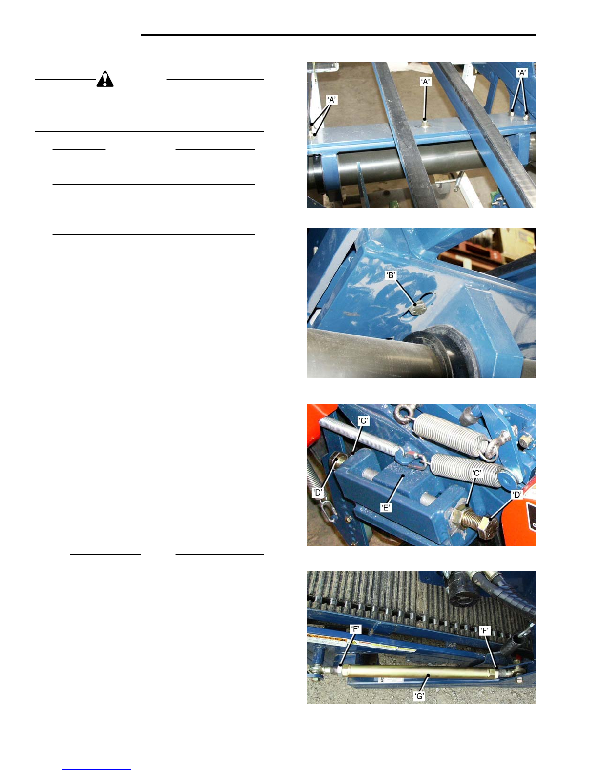
ADJUSTMENTS
Main Conveyor. Tracking Alignment.
WARNING
Do not make any adjustments when the tractor
engine is running. Failure to observe this warning
could result in serious injury or death
IMPORTANT
The Main Conveyo
the tractor.
NOTE
For clarity the photogra
Pivot Beam during assembly.
To adjust the Conveyor Alignment:
• Back-off the Lockn
‘snug’, (approximately two turns).
• The bolt hea
• Loo
• Adjus
• Fully tighten Lockn
Cutter Head. Tracking Alignment.
The Cutter Head must track in-line with the Main Conveyor, to ensure that the sod is not cut at an angle, resulting
in cone shaped rolls.
To adjust the Cutter Head alignment:
• Loo
• Turn the Side
• Re-tig
5-08
sen Locknuts ‘C’, on the Adjusting Bolts ‘D’.
t the Bolts to move the Block ‘E’, to the
‘front’ or to the ‘rear’, until the Conveyor Frame
is parallel to the tractor, when viewed from in
front of the harvester.
adjustment is completed.
sen the Rod End Locknuts ‘F’ on the Side
Arm Links ‘G
NOTE
The Rod Ends are a Left Hand Thread and a
Right Hand Thread.
or contract, until the Cutter Head Frame is parallel
to the Conveyor Frame.
hten the Rod End Locknuts.
r must be aligned parallel to
phs show the Conveyor
uts ‘A’, until they are just
ds are located in ‘T–Slots’ ‘B’.
uts ‘A’ and ‘C’ when the
’, on both sides of the Cutter Head.
Arm Links on each side to extend,
Page 75
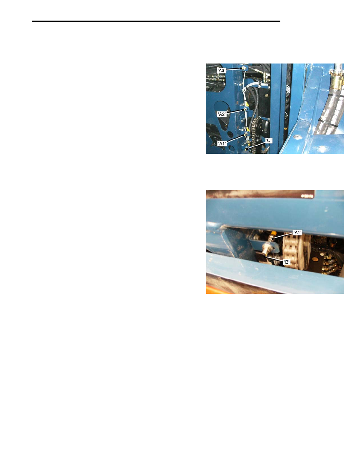
Pallet Lift Forks
The Pallet Lift Forks are controlled by the Computer to
move ‘down’ from the ‘upper’ position, where two layers
of sod are placed on the pallet, to the ‘middle’ position
where one more layer is placed, then to the ‘lower’ where
the remaining layers are stacked.
• When the last
is displayed on the Cab Control Panel Screen.
• The ope
Pad, to lower the Pallet to the ground, as the
harvester continues to move forward.
• An empty pallet is ‘injecte
Proximity Sensor ‘C’),and the operator presses
the ‘EMPTY PALLET’ Pad to return the empty
pallet to the ‘uppe
new operating cycle.
Pallet Lift Forks Sensors.
The Proximity Sensors ‘A1
‘A3 – Lo
Sensor is 1 to 3mm. from the Pallet Lift Sensor Flag ‘B’.
To adjust the Sensor Flag:
wer’ must be adjusted so that the face of the
• Switch the Robomax Syst
• Rai
• Loo
• Slowly move the Senso
• Slowly move the Senso
• Re-tig
se the Lift Forks to the highest position.
sen the two bolts in the Sensor Flag.
LED on the Control Pan
LED indi
hten the Sensor Flag Bolts.
layer is stacked, ‘FULL PALLET’
rator presses the ‘UNLOAD PALLET’
d’ (this is detected by
r’ position, ready to start a
– Upper’, ‘A2 – Middle’ and
em to ‘ON’
r Flag ‘DOWN’ until the
el indicates ‘OFF’.
r Flag ‘UP’ until the
cates ‘ON’.
ADJUSTMENTS
5-09
Page 76

Page 77

ROBOMAX
SECTION 6
AUTO–STEER
Set– Up and Operation.
CONTENTS
Cutting ‘Starting Strip’. 6-1
Cam Roller and Roller Arm Position 6-1/6-2
Fine Adjust Control 6-3
Shoe Arm Adjustment 6-3
Guide Shoe Adjustment 6-4
Re-Set Cylinder Chain Adjustment 6-4
‘Stop Bolt’ Adjustment 6-4
Tracking Adjustment 6-5
Sensitivity Adjustment 6-6
Page 78

Page 79
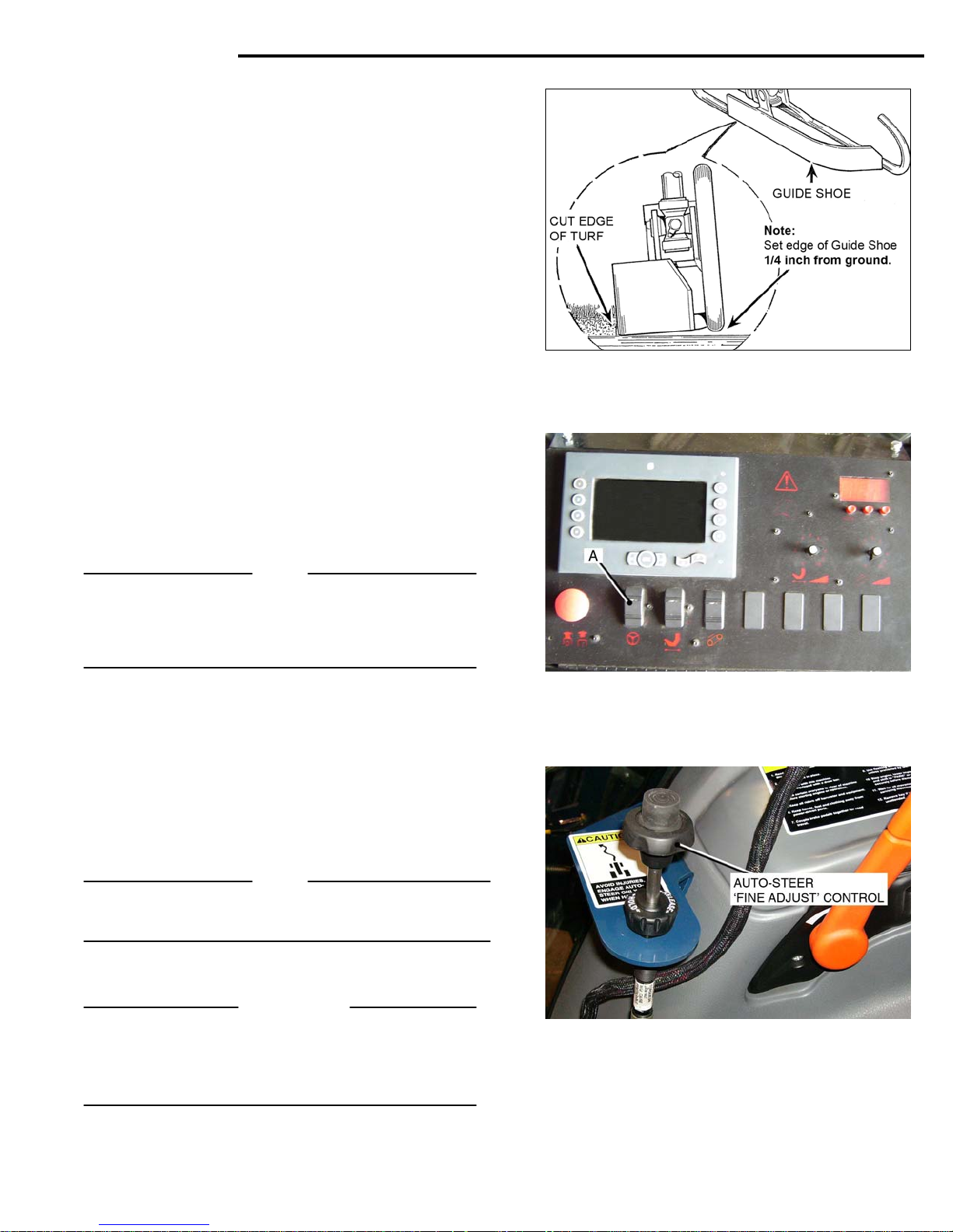
AUTO-STEER
Auto-Steer
Set-up and Operation.
When the Au
the machine is ready to commence harvesting, it is important
before starting, that the Auto-Steer final set-up is carried out
by following the instructions below.
Fig.6-01
A starting strip of turf must be cut ‘manually steering’, this
creates the turf ‘edge’ for the Guide Shoe to follow.
• Start the tract
Engage 1st Gear, the tractor will move forward.
• Push the Cutter He
Using manua
The starting strip must
correct operation of the Auto-Steer.
Fig.6-02
When the starting strip has been cut :
• Position the h
• Switch the Au
NOTE
If the Guide Shoe lowers on the ‘un-cu
Steer is switched ‘ON’, s
set cylinder will move the Guide Shoe ‘off ’ the un-cut turf,
then switch the Auto-Steer back ‘ON’.
Fig.6-02
Fig.6-03
• Selec
• Lower the Cu
• Contin
Control to trim any waste. Each revolution of the Control
knob will give approximately ¼ inch of lateral movement
of the Guide Shoe.
If the Auto-Steer works satisfactory but the ‘Fine Adjust’
Control Cable has run out of adjustment, re-set the cable
NOTE
If there is a problem with the Auto-Steer during harvesting,
re-set the Auto-Steer in the following sequence
Cam Roller and Roller Arm Position.
IMPORTANT
The Cam, Roller and Stop Pin must be set-up with the Fig.6-03
Stop Pin at the ‘mid-point ’ of its
Sensor Valve End Plate. This is the ‘NEUTR
in the Sensor Valve.
to-Steer System has been initially Set-Up, and
or and set the engine at 1800 RPM.
ad Control Lever ‘forward’, to
lower the Cutter head.
l steering, proceed to cut the starting strip. Fig.6-01
be cut straight, to ensure the
arvester parallel to the start strip, with
the Cutter Side Blade aligned to the ‘cut edge’ of
the turf.
to-Steer ‘ON’, with Rocker Switch ‘A’
on the Control Panel.
t’ turf, when the Auto-
witch the Auto-Steer ’OFF’. The re-
st
t 1
Gear.
tting Head.
ue cutting the second strip, use the ‘Fine Adjust’
travel, in the cavity in the
AL’ position
Continued on the following page.
6-01
Page 80
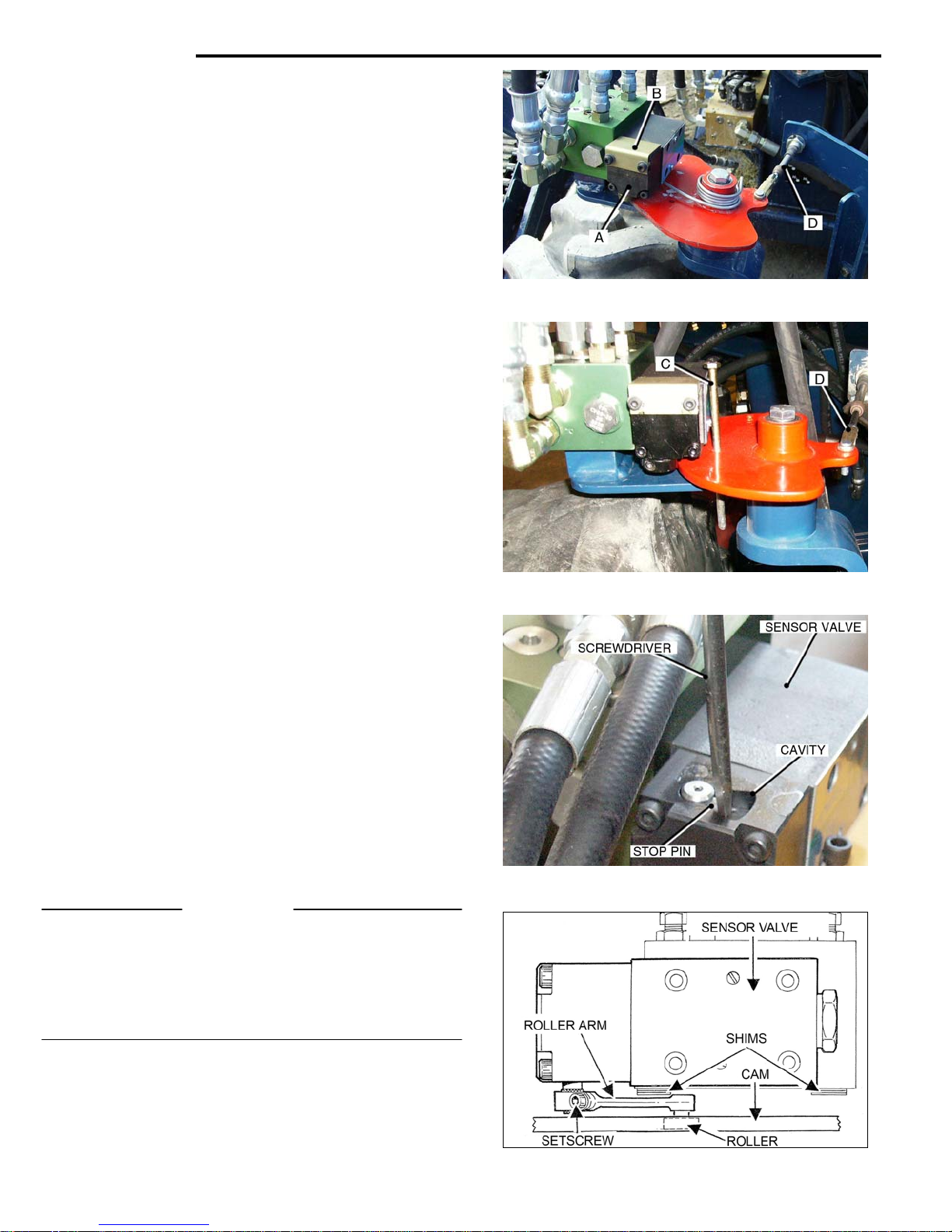
AUTO-STEER
Cam and Roller Arm Set-Up.
The recommended method of setting the Auto-Steer is:
• Pos
• With the Auto-Steer ‘OF
• Stop the harv
The harvester will be parallel to the cut edge, the steering
wheels ‘straight ahead’, and the cutter head ‘down’.
Switch the Auto-Steer ‘ON’. Turn the Tractor ‘OFF’.
Fig.6-04 Fig.6-04
• Remove the t
Fig.6-05
• Swing the Auto-Steer Guide Shoe ‘left or right’, to
• Ins
• Adjust the Ca
Fig.6-06
• Back-off the Setscre
• Use a ‘flat blade’ scre
• The Sen
‘NEUTRAL‘ pos
Fig.6-07
• Push the Roll
• Adjus
• Che
• Tighten the Roller Arm Set
IMPORTANT
Before operating the Auto-Steer remove the ¼ inch Bolt from
the Cam. Failure to do
Also
Fill the cavity around the Stop Pin with ‘white grease’ to prevent
corrosion forming on the Roller Shaft, causing it to ‘stick’ and
adversely affecting the operation of the Auto-Steer
Position the Sensor Valve End Plate Cover, complete with the
rubber seal, re-fit the 40mm Lg. Socket Head Screws.
Replace the Top Cover Plate.
6-02 Fig.6-07
ition the Harvester ‘ready to cut’.
F’, cut a strip of turf, for a
minimum distance of 20 feet. It must be cut str
ester.
wo 5x40mm Socket Head Screws from
the Sensor Valve End Plate ‘A’ and rem
Plate Cover ‘B’, c
align the ¼ inch hole in the Cam with the hole in the
Support Plate.
ert a ¼ inch Bolt ‘C’, through the holes to lock the
Cam in position.
‘mid-point’ of its stroke travel, and lock it in place.
(see Fig.6-04)
the Roller Shaft, (See Fig.6-07).
its ‘mid-point’ of trav
Pin in this position.
sor Valve Internal Spool will now be in the
the Cam.
t the Roller Arm ‘up or down’ on the shaft, to
get maximum surface contact between the Roller and
the Cam.
ck that the Roller Arm is fully engaged on the
knurled portion of the Roller Shaft.
omplete with Rubber Seal. .
ble ‘D’ (attached to the Cam), to the
w that clamps the Roller Arm to Fig.6-05
wdriver to turn the Stop Pin to
el in the cavity. Hold the Stop
ition.
er Arm until the Roller is ‘hard’ against
screw. Fig.6-06
so will result in damage to the system.
ove the End
aight.
Page 81
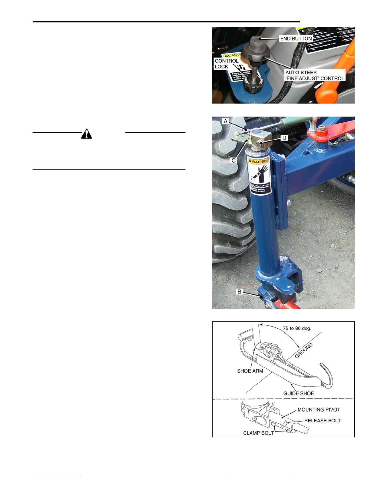
AUTO-STEER
Fine Adjust Control.
As noted in Figure 6-03, the Fine Adjust Control allows the
operator to trim the waste strip. It is recommended that it
is set-up as follows:
Fig.6-08
Set the Fine Adjust Control to its ‘Mid-Point’ by:
• Rele
• Press the En
• Re-tig
Actuator Column.
Spring Tension Adjustment.
CAUTION
The Top Lever Arm is under spring tension.
Exercise care when removing the Cable Clevis End from
the Top Lever Arm, or when loosening the Lever Arm
Clamp Bolt
Fig.6-09
Position the Guide Shoe against the cut edge of turf :
• Remove
• Loo
The Top Lever Arm ‘C’, sh
imately 60 de
If the Lever Arm rotates ‘back’ less tha
re-set it by :
• Loo
Lever Arm to the required setting.
• Tighten the Clamp Bolt D’.
• Fit a 1¼ in. wren
• Refit the Clev
Shoe Arm Adjustment
Fig.6-09
Fig.6-10
The Guide Shoe Arm must be at a 75 to 80 degre
the ground.
To adjust the Shoe Arm angle :
• Loosen the two Clamp Bolts in the Mounting Pivot.
• Tighten the Relea
• Back-off the Rele
Fig.6-10
asing the Control Lock.
d Button, and slide the Control Knob
‘IN’ or ‘OUT,’
hten the Control Lock.
sen the Shoe Arm Clamp Bolt ‘B’.
grees, releasing the spring tension.
sening the Clamp Bolt ‘D’, and turning the
rotate the Top Lever Arm ‘back’ 60 de
against the spring pressure.
rotate the Shoe Arm to the correct angle.
to find the mid-point of travel.
Clevis End ‘A’, from Top Lever Arm ‘C’.
ould rotate ‘clockwise’ approx-
n 60 degrees,
ch on the Lever Arm Boss and
grees,
is End ‘A’.
se Bolt to ‘open up’ the clamp and
ase Bolt and tighten the Clamp Bolts.
Fig.6-08
e angle to
6-03
Page 82
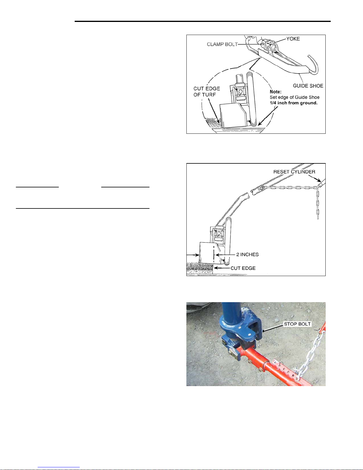
AUTO-STEER
Guide Shoe Adjustment.
Fig.6-11
The Guide Shoe must be correctly adjusted, as follows :
• Loo
• Tighten the Y
Re-set Cylinder Chain Adjustment.
Fig.6-1
Fig.6-12
The Re-set Cylinder must be attached to the chain links
at a point that allows the Guide Shoe to travel no more
than 2 inche
un-cut turf.
IMPORTANT
The Re-set Cylinder chain links must be adjusted
before the adjustment to the Stop Bolt. See Fig.6-13.
STOP BOLT ADJUSTMENT.
Fig.6-12
Fig.6-13
The Stop Bolt determines where the Guide Shoe will
‘drop’ on the ground when
For most harvesting conditions the Stop Bolt is adjusted
to place the Guide Shoe 1 to 2 inches from the ‘cut e
If the conditions require adjustment to the Guide Shoe :
‘Away’ from the cut edge :
• Back-off the Lockn
‘Closer’ to the c
• Turn the Stop
After adjustment tighten the Locknut.
Fig.6-13
6-04
sen the Yoke Clamp Bolt and rotate the Guide
Shoe until there is ¼ inch clearance between the
inside edge
s past the ‘cut edge’ and onto the
of the shoe and the ground.
oke Clamp bolt.
the Auto-Steer is activated.
dge’
ut and turn the Stop Bolt ‘IN’.
ut edge :
bolt ‘OUT’.
1
Page 83
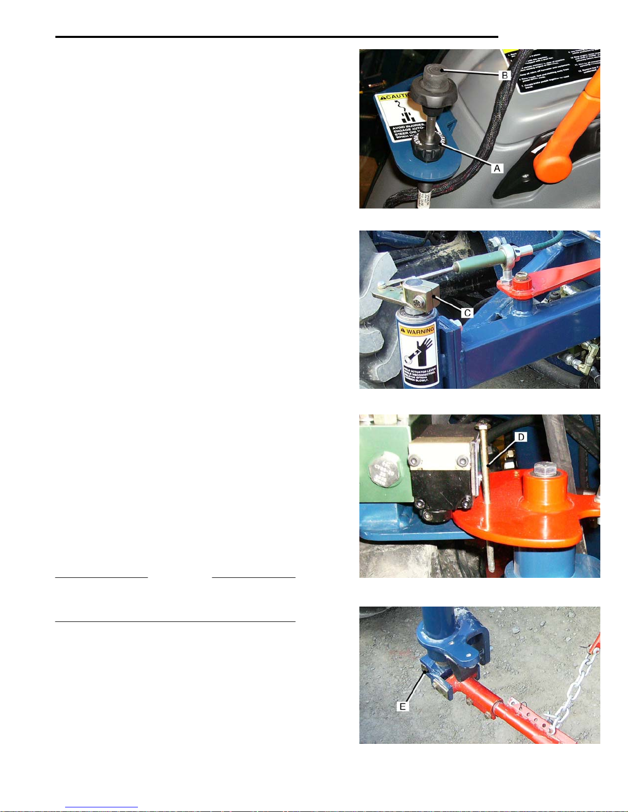
AUTO-STEER
Tracking Adjustment.
The recommended method of setting the tracking is :
• Pos
• With the Auto
• Stop the harv
The harvester will be parallel to the cut edge, the
steering wheels ‘straight ahead’, and the cutter head down.
• Switch the Au
Fig.6-14
To Set the Fine Adjust Control to ‘Mid-Point’:
• Rele
• Press on the
• Re-tig
Fig.6-15
• Position the
• Fit a 1¼ in wrench on the T
Continue below
Fig.6-16
• Use the wrenc
• Insert a ¼ in. Bolt ‘D’, in the holes to lock the Cam in
The Sensor Valve will now be in the ‘NE
Fig.6-17
To prevent any movement of the Top Lever Arm and
Spring Column Shaft, use the wrench to hold the Top
Lever Arm firmly, against spring pressure and:
• Loo
• Tighten the S
IMPORTANT
Before operating the Auto-Steer the ¼ in. bolt must be Fig.6-16
removed fro
damage to the Auto-Steer mechanism.
Fig.6-17
ition the harvester ‘ready to cut’.
-Steer switched ‘OFF,’ cut a strip of turf,
for a minimum distance of 20 feet, it m
straight.
ester.
to-Steer ‘ON’, the Guide Shoe will drop.
ase the Fine Adjust Control ‘lock’ ‘A’.
End Button ‘B’, and slide the Control
Knob Rod ‘in
hten the Control ‘lock’.
until the ¼ inch hole in the Cam aligns with the hole Fig.6-15
in the Support Plate.
place.
sen the Shoe Arm Clamp Bolt ‘E’, and move
the Guide Shoe against the ‘cut edge’ of the turf.
m the Cam. Failure to do so will result in
or out’, to find its mid-point of travel.
Guide Shoe against the cut edge of turf.
op Lever Arm Boss ‘C’.
h on the Lever Arm to rotate the Cam
hoe Arm Clamp Bolt.
ust be cut
Fig.6-14
UTRAL’ position.
6-05
Page 84
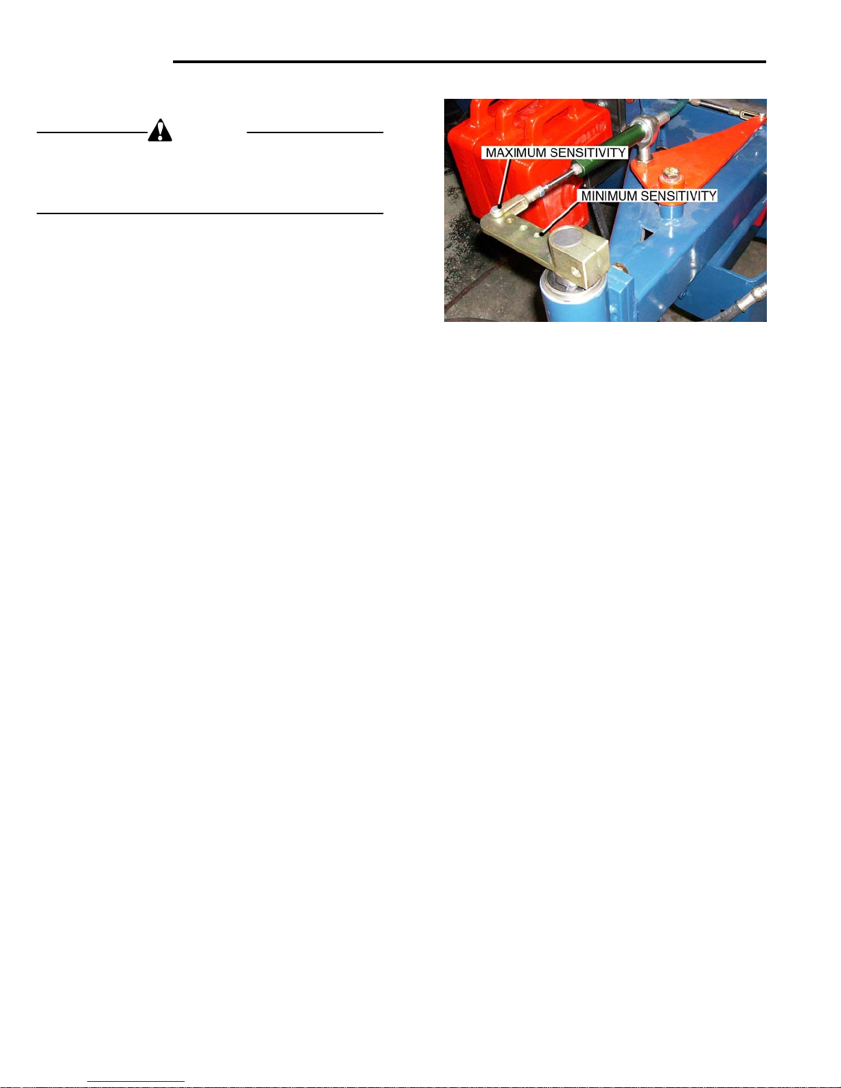
AUTO-STEER
Sensitivity Adjustment
CAUTION
The Top Lever Arm is under spring tension.
Exercise care when removing the Cable Clevis End from
the Top Lever Arm, or when loosening the Lever Arm
Clamp Bolt
Fig.18
On initial set-up, the Cable End from the Sensitivity Valve is
attached at the ‘outer’ hole, (maximum sensitivity), in the
Top Lever Arm.
Operating conditions may require adjustment to the degree
of sensitivity. Fig.6-18
• To ‘decre
Clevis progressively ‘inward’, on the Lever Arm,
to obtain the desired setting.
6-06
ase‘ sensitivity, move the Rod End
 Loading...