

Page 1
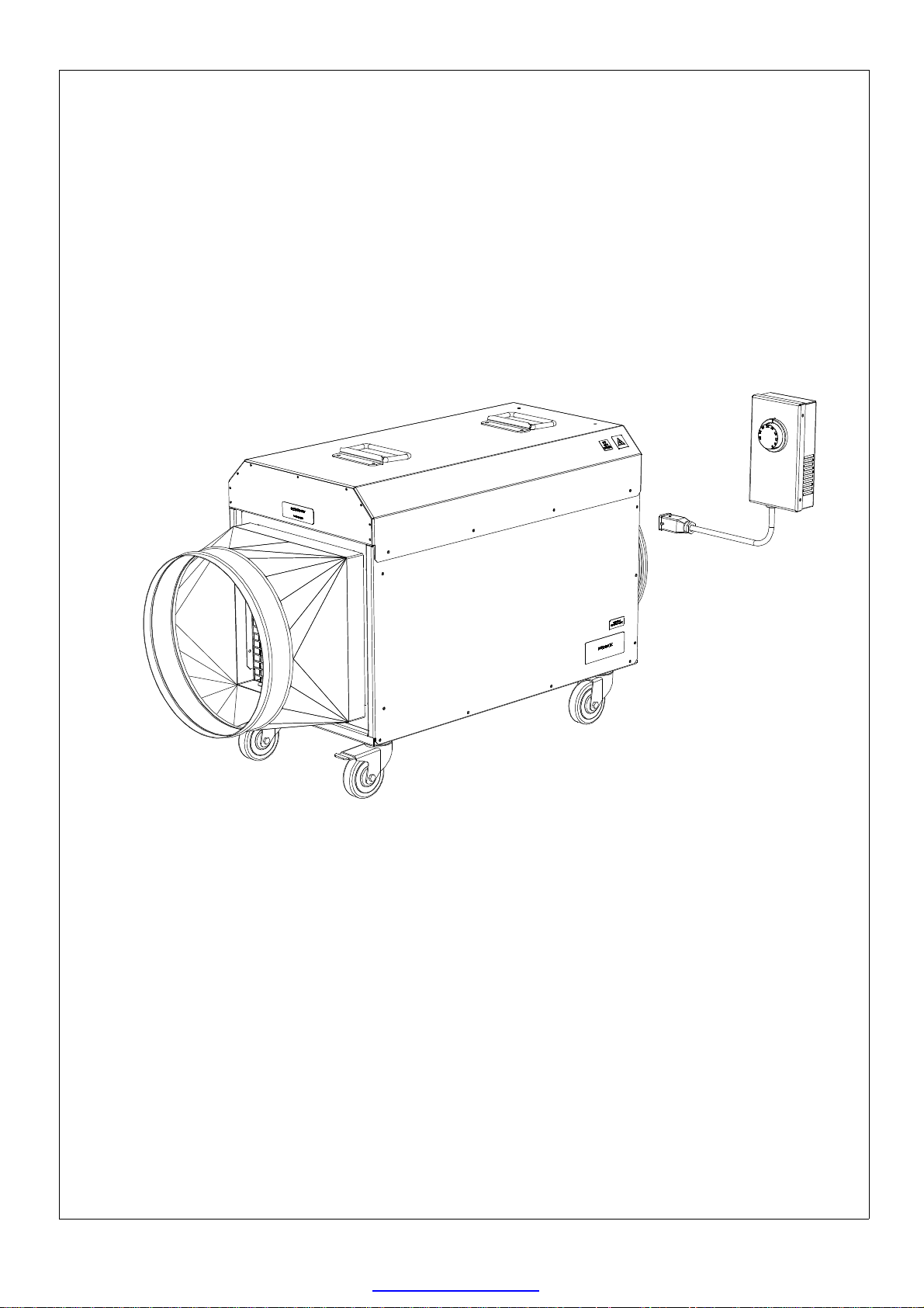
FFHT 32
FFHT32-18
3 PHASE 400V ELECTRIC HEATER
PRODUCT MANUAL
P 1 of 13
PDF created with pdfFactory trial version www.pdffactory.com
Page 2
WARNINGS
These instructions should be read by:
The specifying engineer.
The installation engineer.
The user.
The service engineer.
Failure to follow these instructions may result in risk of•
personal injury or damage to the equipment.
Damage due to a failure to follow these instructions will •
invalidate the warranty.
The appliance must be commissioned & serviced by qualified •
engineers in compliance with local regulations.
The appliance must be switched off and disconnected from•
the power supply before any work is carried out.
There are no user controls inside the appliance casing.•
Do not cover the appliance.•
Do not use in the vacinity of a pool, bath or shower.•
An air gap of at least 300mm should be allowed at the rear of•
the unit to ensure a clear airflow. Do not site the unit close to
soft fabrics or combustible materials. Do not obstruct the outlet grill.
Allow the unit to cool by running fan only for a minimum of•
5 minutes before switching off.
Do not disconnect the appliance from the supply under load.•
For internal use only. Do not use out of doors.•
Extension cables should be correctly rated for the load,fully•
unwound and never run through water or over sharp edges.
Ensure that locking castors are engaged before running the•
unit.
This unit can operate with a maximum of 10M of 300mm duct. •
Ducting should be kept as taught and straight as possible.
The machine is not phase rotationally sensitive.•
This is a class 1 product and requires an Earth connection.•
Warning! Fan liable to start without warning.•
Do not use this appliance with plastic ducting.•
P 2 of 13
PDF created with pdfFactory trial version www.pdffactory.com
Page 3
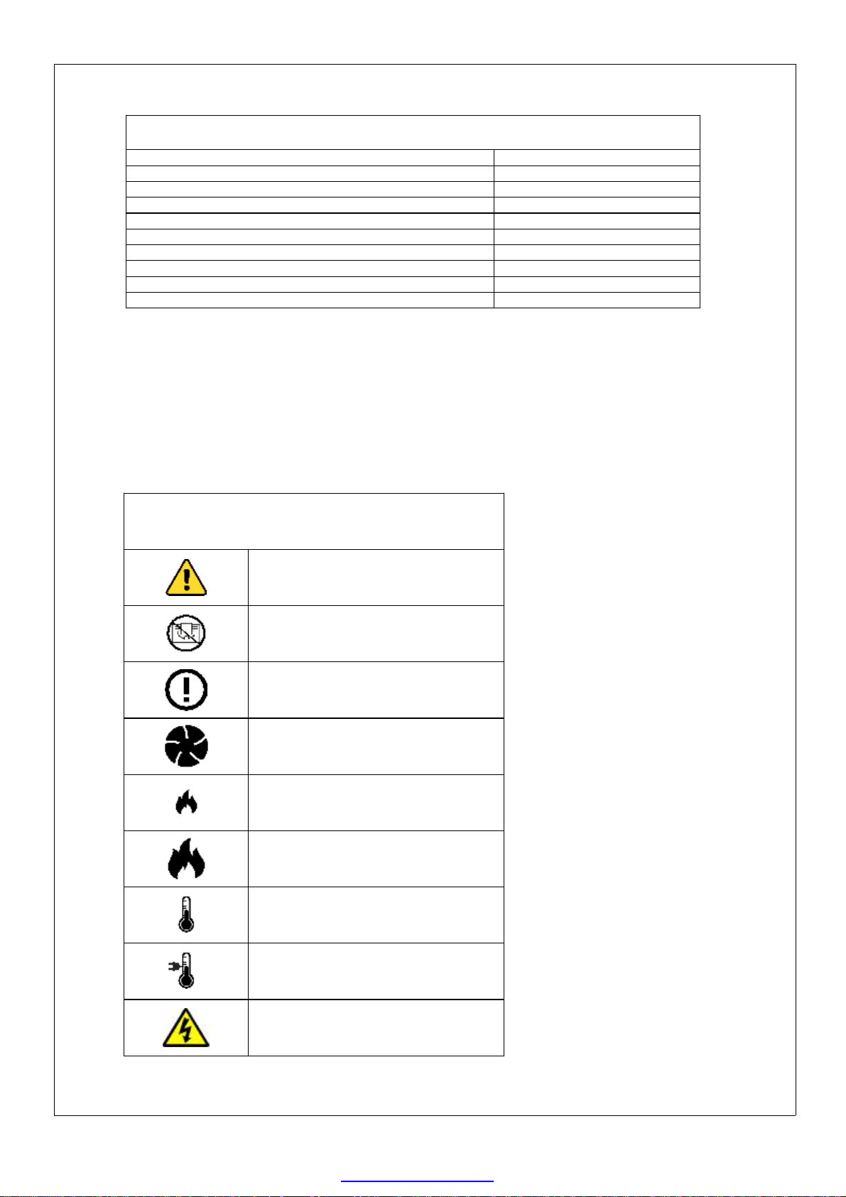
TECHNICAL SPECIFICATIONS. FFHT32-18
Heating capacity. 18 kw
Power supply.
Maximum running current. 28A
Airflow. 1533.6 M3h
Weight . 29.5 kg
Noise level at 3M. 73 dB(A)
IP Rating. IP20
Maximum operating temperature. 40 ºC +/- 3ºC
Maximum ducting length (300mm duct) See P6. 10M
Temperature rise at 15 ºC ambient. (Nominal) 74 ºC
400v. 3P+N+E. 32A. 50Hz.
Standards applied:
BE EN 12100. 2010.
BS EN 60335-1. 2012.
BS EN 60335-2. 2009.
BS EN 61000.
MACHINE AND INSTRUCTION ICONS
Important information
Warning. In order to avoid
overheating, do not cover the
heater.
Safety limit thermostat.
Fan on/off
Heat setting I on/off.
Heat setting II on/off
Thermostat. (Onboard)
Thermostat. (Remote)
Risk of electric shock. Isolate
from power supply before
removing cover.
P 3 of 13
PDF created with pdfFactory trial version www.pdffactory.com
Page 4

Specifications:
The FFHT32 is an 18kw 3 phase industrial electric fan heater.
The appliance is connected to a 400v 32Amp 3P+N+E 50Hz power supply and comes fitted
with the appropriate 5 pin plug. A neutral is required. This appliance requires an Earth
connection.
The machine is not phase rotationally sensitive !
The FFHT32 is fitted with a high quality axial fan which will allow it to operate with up to 10M
of 300mm duct. (See P 6)
The FFHT32 is fitted with an onboard thermostat as standard. It is also supplied with a remote
thermostat as standard. (See P 5)
The FFHT32 is supplied with locking castors to the front of the machine.
Setup and operation:
To start:
Please note ! the control panel is at the rear of the appliance. (See P7)•
Site the appliance on a firm level surface and apply the castor brakes. Do not•
operate the unit without applying the brakes.
Connect the machine to the appropriate power supply.•
Switch the fan rocker switch to I. ( please note! the heat rocker switches will•
not operate the heating elements unless the fan switch is on).
Switch the heat rocker switch to I- 12kw or I+II- 18kw.•
Set the thermostat to the desired temperature.•
To stop:
Switch the heat rocker switches to 0 and allow the fan to run for a minimum•
of five minutes to cool the machine. Failure to follow this procedure will
damage sensitive components and invalidate the warranty.
Switch the fan rocker switch to 0 when the heat has dissipated.•
If the heat has not fully dissipated the fan may 'run on' automatically. (see P7)•
If the heater is not in regular daily use disconnect from the power supply.•
P 4 of 13
PDF created with pdfFactory trial version www.pdffactory.com
Page 5
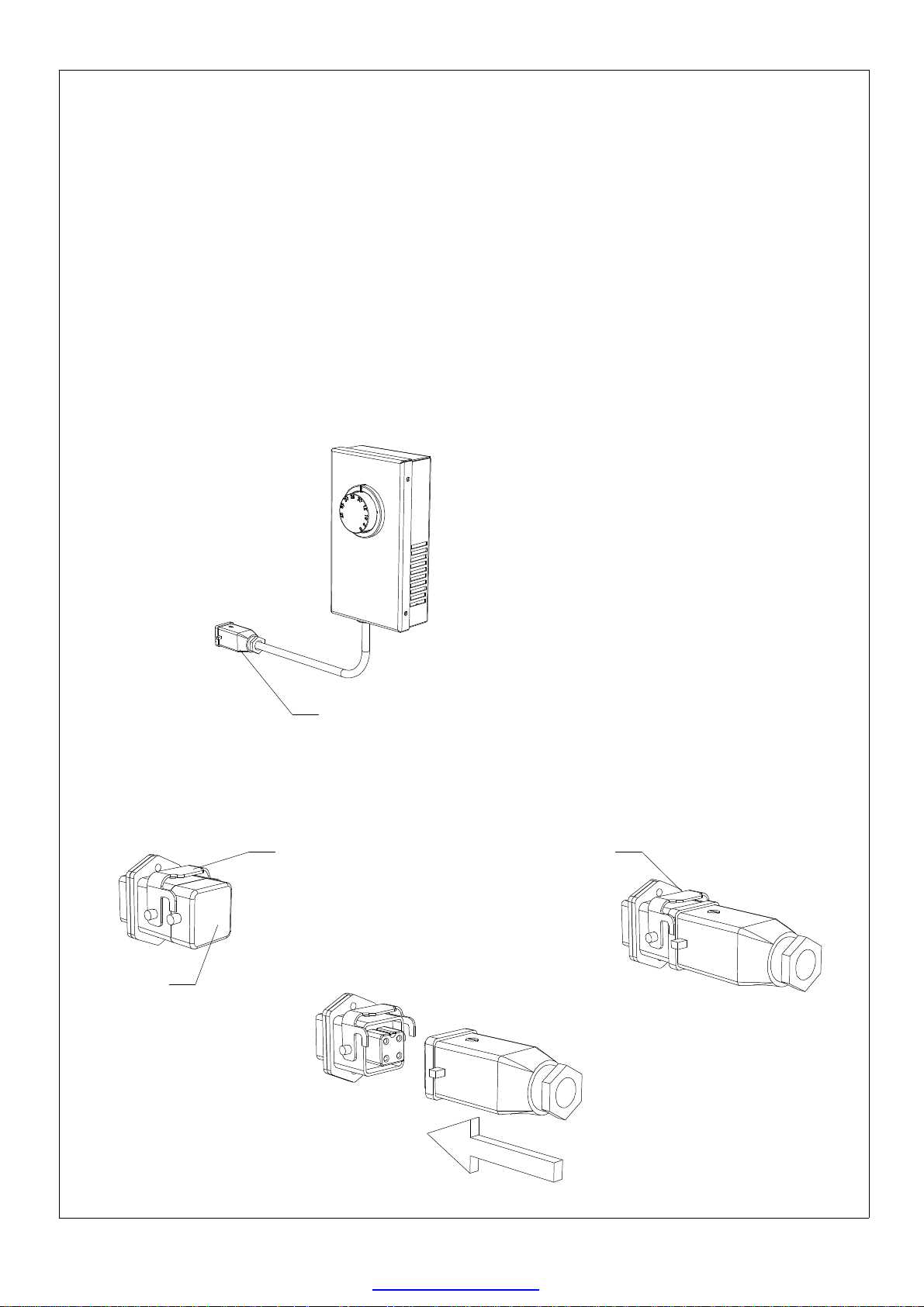
Using the remote thermostat:
Set the onboard thermostat to 0. Please note! failure to set the onboard thermostat•
to 0 will prevent the remote thermostat from operating.
Lift the retaining catch and remove the protective cap from the remote thermostat •
socket. The thermostat socket is located on the control panel at the rear of the
machine.
Fit the remote thermostat plug to the socket and secure in place with the retaining •
catch.
The remote thermostat is now ready for use.•
Always refit the protective cap when not in use.•
Remote thermostat:
Remote thermostat socket::
Protective cap.
Remote thermostat
plug.
Retaining catch
Retaining catch
engaged.
P 5 of 13
PDF created with pdfFactory trial version www.pdffactory.com
Page 6
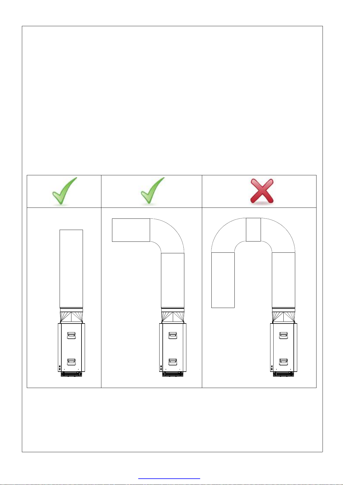
Using flexible ducting:
This appliance is designed to be operated with a maximum flexible duct length •
of 10M.
300mm ducting should be fitted. Do not use reducers.•
Aluminium foil duct is recommended. Do not use plastic flexible duct.•
Always keep duct lengths to a minimum.•
Always keep duct runs as straight as possible.•
Poorly run flexible ducting can cause overheating of the machine. Do not•
run ducting through 180 degrees.
P 6 of 13
PDF created with pdfFactory trial version www.pdffactory.com
Page 7
Protective /safety devices:
The FFHT32 is fitted with a safety limit thermostat. This is a fail-safe device.•
Should the maximum design operating temperature be exceeded it will shut down
the heater. This device requires a manual reset and should only operate in the event
of a fault. Any activation of this safety device should be investigated by a competent
engineer.
The FFHT32 is fitted with a limit thermostat. Should the maximum operating •
temperature be exceeded it will shut down the heating elements and leave the fan
running. This device will automatically reset once the temperature falls to an
acceptable level.
The machine is fitted with an automatic fan run-on thermostat. If the machine is •
shut down without running on fan only for 5 minutes to cool down, this device will
activate and allow the fan to keep running. This should not be used to routinely shut
down the machine.
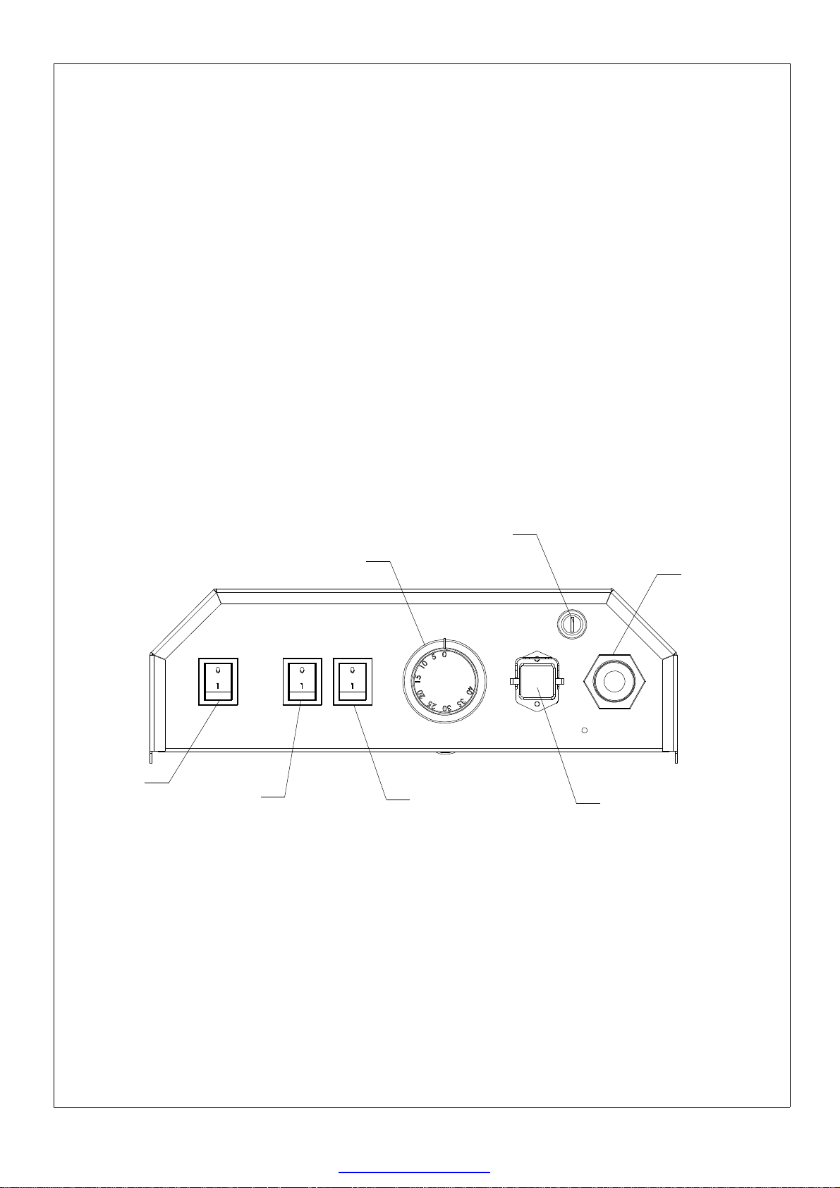
Rear view. Control panel:
Fan on/off.
Onboard thermostat.
Heat I on/off.
Safety limit
thermostat.
Heat II on/off.
Power cable
gland.
Remote thermostat
socket.
P 7 of 13
PDF created with pdfFactory trial version www.pdffactory.com
Page 8
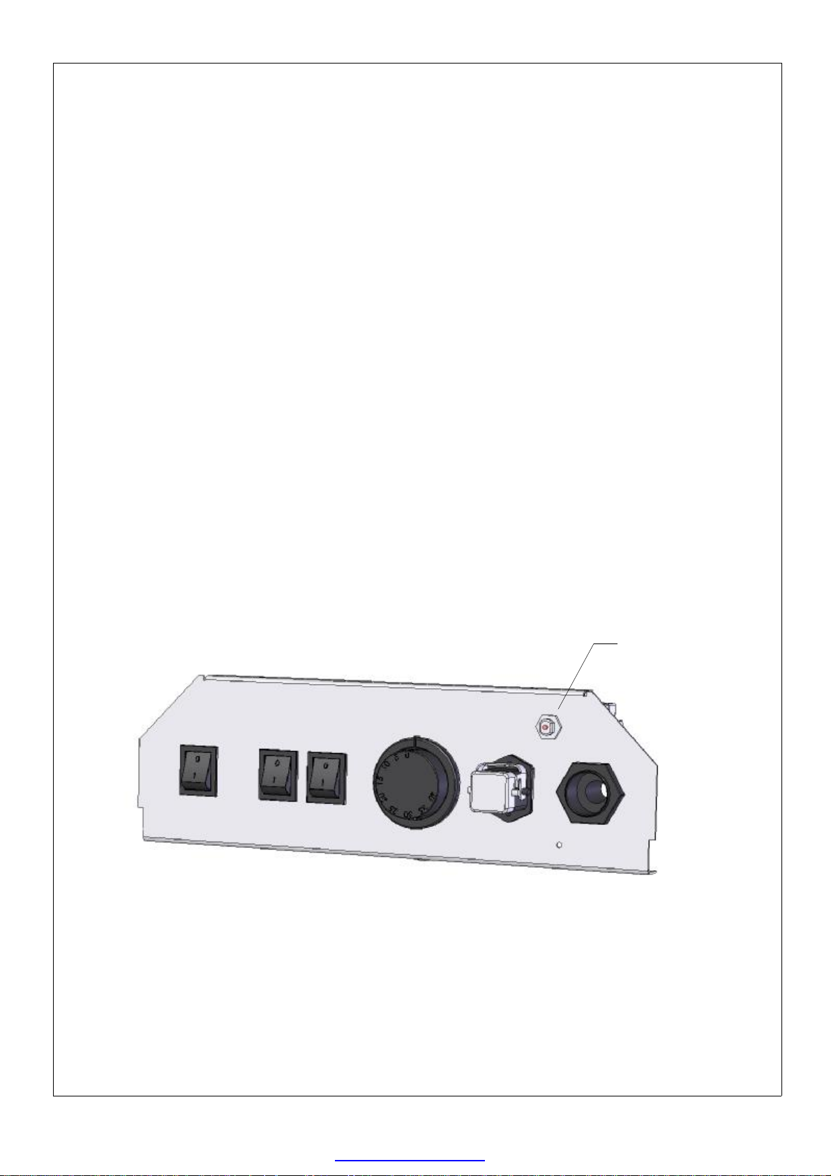
Safety limit thermostat:
Checking and resetting the safety limit thermostat:
Should the safety limit thermostat activate the causes should be investigated.
Remove the black plastic screw cover from the safety limit thermostat.•
If the pink reset button is noticeably pronounced the reset has activated.•
To reset the thermostat press the pink reset button. Allow the machine to fully cool •
down before resetting.
Always replace the screw cap after resetting.•
Reset button
P 8 of 13
PDF created with pdfFactory trial version www.pdffactory.com
Page 9
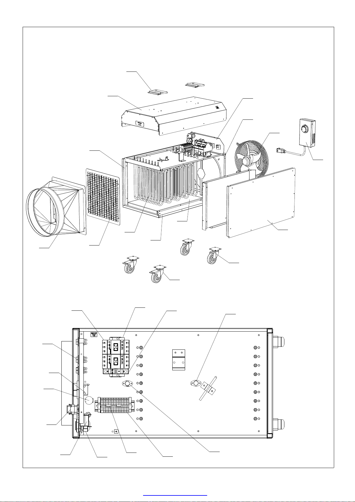
Exploded view:
2
12
13
11
1
14
15
10
3
4
5
6
7
8
28
26
27
25
24
16
23
22
17
21
18
9
19
20
P 9 of 13
PDF created with pdfFactory trial version www.pdffactory.com
Page 10
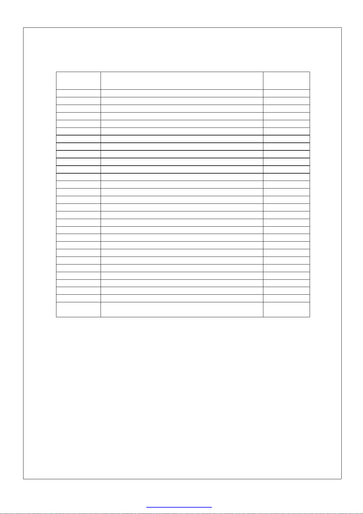
Spare parts:
Drawing
No
1. TOP PANEL BW0202101
2. TRUNK HANDLE ME040316
3. CONTROL PANEL BW0202102
4. REAR PANEL ASSEMBLY BW0202103
5. 250mm AXIAL FAN ASSEMBLY. 230v. FA010102
6. REMOTE THERMOSTAT ASSEMBLY EL040125
7. RIGHT SIDE PANEL BW0202105
8. 75mm CASTOR FIXED. ME0101223
9. 75mm CASTOR SWIVEL C/W BRAKE ME010222
10. BASE PANEL BW0202106
11. FRONT GRILL BW0202107
12. OUTLET ASSEMBLY BW0202108
13. LEFT SIDE PANEL BW0202109
14. GALVANISED METALWORK SET BW0202110
15. 2000w 230v ELEMENT HE010118
16. 32A 230v CONTACTOR EL030814
17. DIN MOUNTED END STOP EL020403
18. MCB 6A SINGLE POLE TYPE C EL010222
19. 70 DEGREE THERMAL CUT-OUT. NC EL010311
20. 50 DEGREE THERMAL CUT-OUT. NO EL010312
21. 6mm TERMINAL ASSEMBLY EL020424
22. TERMINAL LINK EL020426
23. PG21 CABLE GLAND C/W LOCK NUT ME040204
24. SAFETY LIMIT THERMOSTAT EL030417
25. REMOTE THERMOSTAT SOCKET EL020523
26. CAPACITOR 4uf EL030307
27. THERMOSTAT C/W BEZEL & KNOB EL030409
28. 1/0 ROCKER SWITCH EL030235
29.
Description Part No
5 CORE 4mmX1.5M CABLE C/W 32A 5 PIN PLUG.
(Not shown)
EL020128
P 10 of 13
PDF created with pdfFactory trial version www.pdffactory.com
Page 11
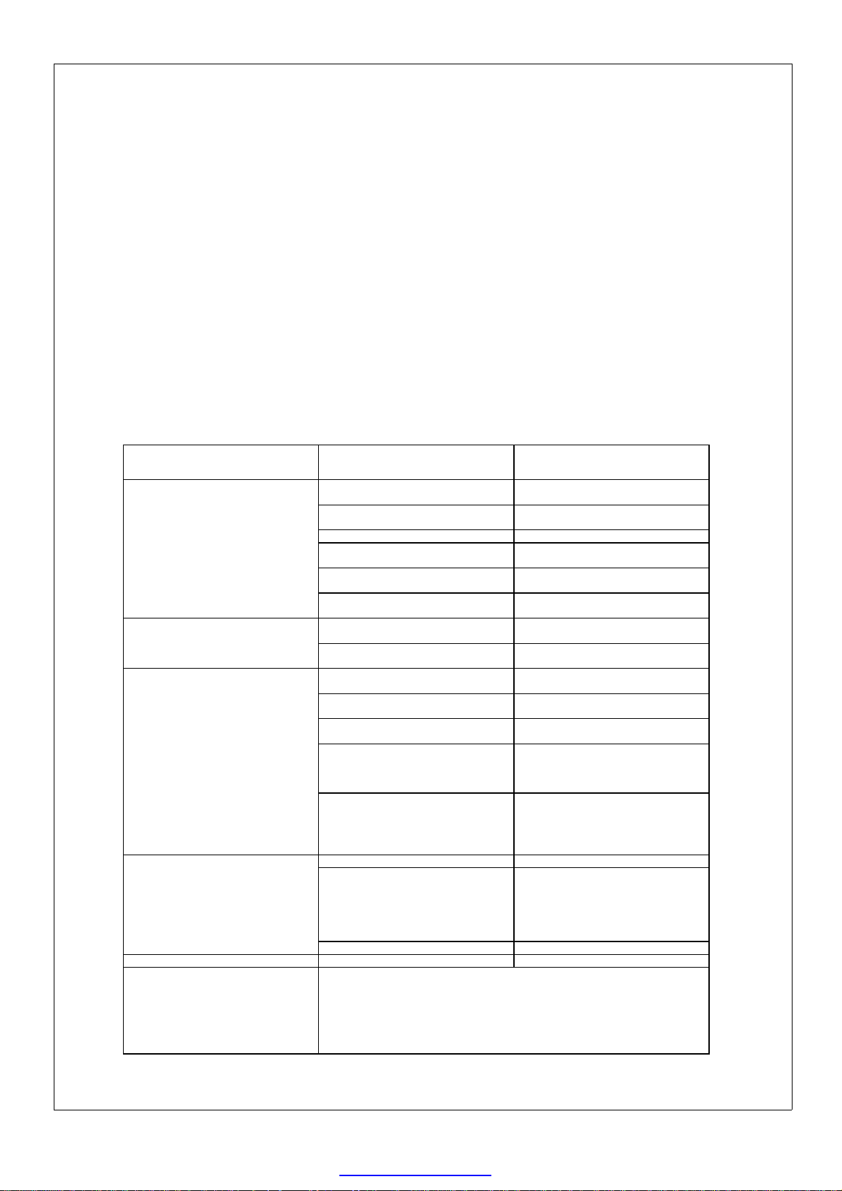
Maintenance:
Fan motors, elements and switch gear are not customer serviceable components.
General maintenance should include regular inspection of:
1: Mains cable. Check for signs of damage to the insulation. Replace if necessary.
2: Air intake & outlet grills: ensure grills are free from accumulated debris. blow out
with compressed air if required.
3: Fixings: Check all fixings are present and secure.
Maintenance carried out by a competent person:
1: Internal cables should be inspected for signs of heat damage and replaced when
necessary.
2: All cable connections should be regularly check and tightened. Particular attention
should be paid to the connections at the contactors.
3: Regularly check the contactors for signs of heat. Replace if necessary.
FAULT POSSIBLE CAUSE SOLUTION
NO HEAT OUTPUT.
REMOTE THERMOSTAT NOT
SWITCHING THE HEATING
ELEMENTS
SAFETY LIMIT THERMOSTAT HAS
ACTIVATED
FAN MOTOR NOT RUNNING.
TEMPERATURE RISE
INSUFFICIENT.
FANS AND OR HEATING NOT
SWITCHED ON.
THERMOSTAT INCORRECTLY SET.
POWER SUPPLY INTERRUPTED. CHECK POWER SUPPLY.
FAULTY ROCKER SWITCH.
FAULTY THERMOSTAT.
FAULTY CONTACTOR.
ONBOEARD THERMOSTAT
INCORRECTLY SET
REMOTE THERMOSTAT PLUG
INCORRECTLY FITTED
AMBIENT ROOM TEMPERATURE
TOO HIGH
EXCESSIVE DUCT LENGTH OR
POORLY ROUTED DUCTING
FAN MOTOR FAILURE
CORRECT SHUTDOWN
PROCEDURE NOT FOLLOWED
FAILED SAFETY LIMIT
THERMOSTAT
POWER SUPPLY INTERRUPTED. CHECK POWER SUPPLY.
FAN MOTOR OVER HEATED
FAULTY ROCKER SWITCH REPLACE ROCKER SWITCH
THE MACHINE SHOULD DELIVER A TEMPERATURE RISE OF
APPROXIMATELY 74ºC AT AMBIENT TEMPERATURE OF 15ºC. SHOULD
THE MACHINE FAIL TO DO THIS CHECK THE POWER SUPPLY AND THAT
THE THERMOSTAT IS TURNED FULLY CLOCKWISE.
IT SHOULD BE NOTED THAT THE MAXIMUM AMBIENT TEMPERATURE
THE MACHINE WILL RUN AT IS 40ºC +/- 3ºC. ABOVE THIS THE HEATING
ELEMENT CONTACTORS WILL NOT OPERATE.
CHECK ALL SWITCHES ARE ON.
TURN THERMOSTAT KNOB FULLY
CLOCKWISE.
CHECK SWITCHES AND REPLACE
IF NECESSARY.
CHECK THERMOSTAT AND
REPLACE IF NECESSARY.
CHECK CONTACTOR AND
REPLACE IF NECESSARY.
SET ONBOARD THERMOSTAT TO
0. (SEE P 5)
GO THROUGH FITTING STEPS ON
P5.
DO NOT OPERATE IN AN AMBIENT
TEMPERATURE ABOVE 40ºC.
SHORTEN DUCT LENGTH OR RE-
ROUTE
TEST FAN MOTOR AND REPLACE
IF REQUIRED.
ALLOW THE MACHINE TO FULLY
COOL AND FOLLOW CORRECT
SHUTDOWN PROCEDURE.
(SEE P4)
THE SAFETY LIMIT THERMOSTAT
IS A FAIL-SAFE DEVICE. CHECK
THE CAPILLARY TUBE AND BULB
FOR SIGNS OF DAMAGE.
REPLACE IF REQUIRED.
THE FAN MOTOR HAS A HIGH
TEMPERATURE PROTECTIVE
DEVICE FITTED INTO THE
WINDINGS. ALLOW THE MACHINE
TO FULLY COOL AND ATTEMPT
TO START.
P 11 of 13
PDF created with pdfFactory trial version www.pdffactory.com
Page 12
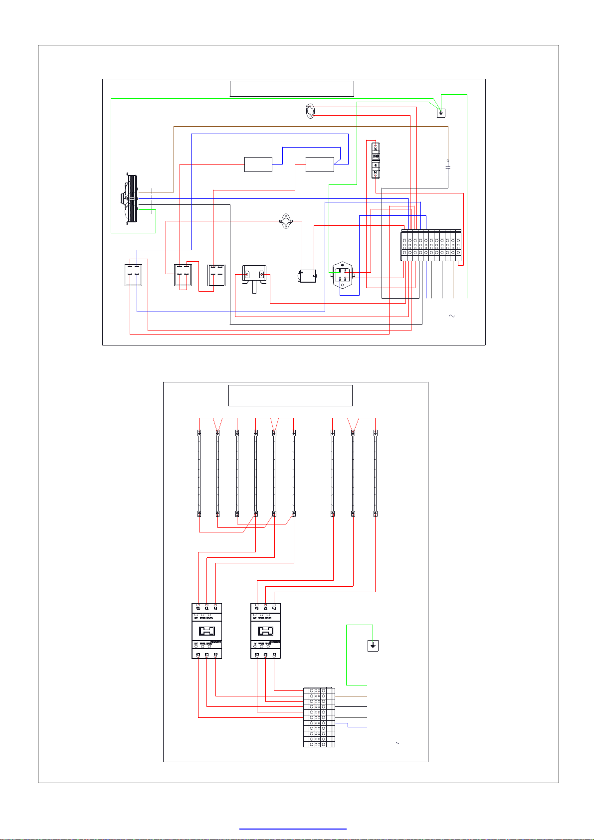
250mm
Axial fan.
230v.
34
22
21
33
Fan fly-lead
Blue
Black
Fan on
27
Brown
30
29
28
Heat. Low Heat. High
29
FFHT32-18 WIRING DIAGRAM
30
CONTROL CIRCUIT
LC1D32 contactor
230v coil.
Fan run on
thermostat.
°
50C. NO.
12kw 18kw
27
Over temp
thermostat.
°
70C. NC.
31
Thermostat
24
25
LC1D32 contactor
A1
3135
26
26
Safety limit
thermostat.
17
18
230v coil.
K2
23
36
16
35
A2A1K1A2
34
MCB. 6A TYPE C.
1
36
19
20
32
In-line connector
crimp.
18
21
19
33
17
32
23
1234567891011
Terminal block.
20
16
24
22
25
N E
SUPPLY:
Black
NOTE! Links between terminals
4&5, 6&7, 8&9, 10&11.
C1
Capacitor
4 uf
1
L2L3
L1
32A. 50Hz.400V.3P+N+E
P1 of 2.
15
15
Heating elements
14
14
13
11
12
K1
3
7
5
K1: Contactor.12kw. LCD132.
K2: Contactor. 18kw. LCD132.
FFHT32-18. WIRING DIAGRAM.
POWER CIRCUIT.
15 15
1213
14
11
10
9
8
NOTE! Links between terminals
4&5, 6&7, 8&9, 10&11.
K2
2
6
4
2
11
3
4
5
8 9 10
6
7
7
6
5
2 3 4
1
Terminal Block
15
15
9
Y/G
Brown
Black
Grey
Blue
8
E
L1
L2
L3
N
400v. 3P+N+E
SUPPLY:
. 32A. 50Hz.
10
P2 of 2.
P 12 of 13
PDF created with pdfFactory trial version www.pdffactory.com
Page 13
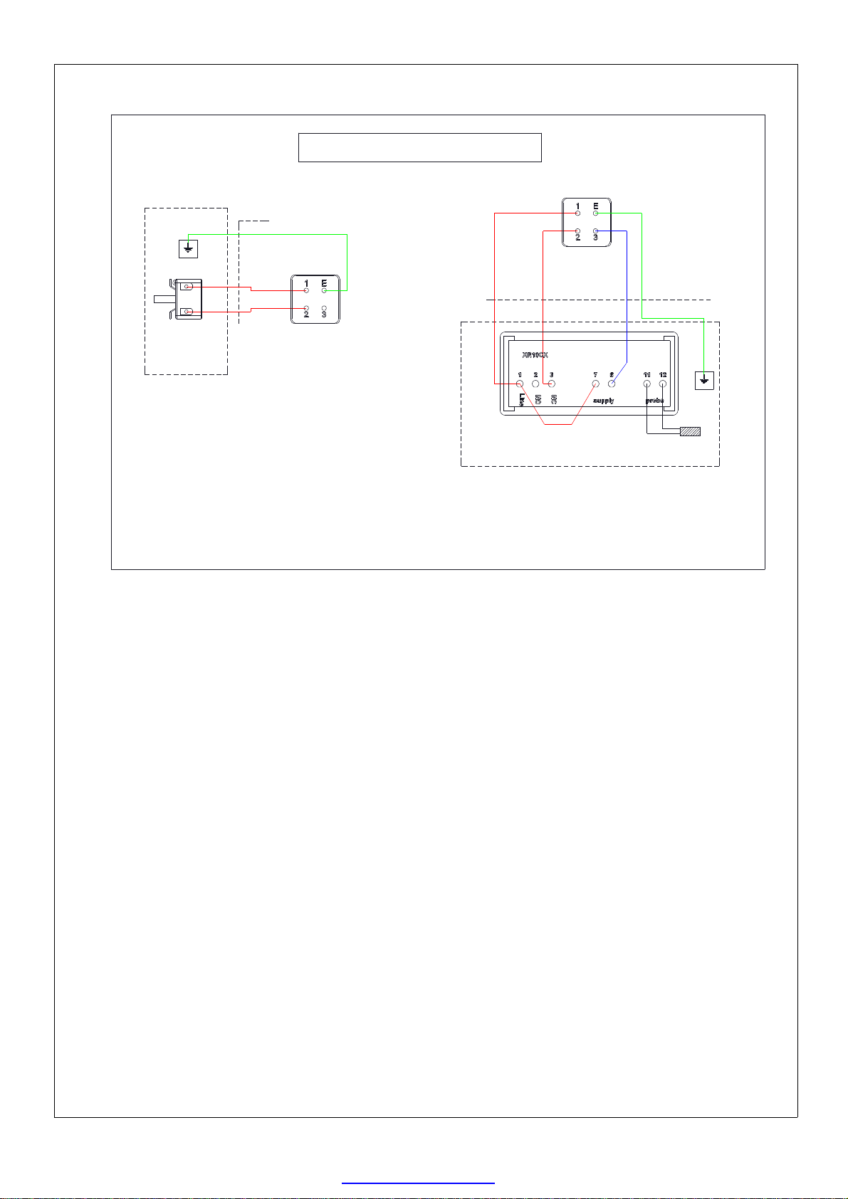
MECHANICAL THERMOSTAT.
STANDARD PART.
0.75mm 3 core cable x 5M.
FFHT32-18. WIRING DIAGRAM.
REMOTE THERMOSTAT.
0.75mm 4 core
cable x 5M.
DIGITAL THERMOSTAT.
OPTIONAL EXTRA.
Remote thermostat
plug.
Thermostat
Remote thermostat
box.
Ensure blue cable is appropriately
labelled at each end.
Remote thermostat
plug.
XR10 digital controller
Probe
Remote thermostat box.
P 13 of 13
PDF created with pdfFactory trial version www.pdffactory.com
 Loading...