

Page 1
bfothec
Owner’s Manual
FAX=i1®
Page 2

Page 3

This unit generates, uses and can radiate radio frequency energy and if not instalied
and used in accordance with the Owner's Manuai, may cause interference to radio and
television reception. It has been tested and found to comply with the limits for a Class
B computing device in accordance with the specifications of Subpart J of Part 15 of the
FCC rules, which are designed to provide reasonable protection against such
interference in a residential installation. However, there is no guarantee that
interference will not occur in a particular installation. If this unit does cause
interference (such as static) to radio or television reception, which can be determined
by turning the unit off and on, the user is encouraged to try to correct the interference
by employing one or more of the following measures:
- change the location of the receiving antenna (indoor type)
- move the unit away from the radio or TV
- plug the unit into a different outlet so that the unit and the radio or TV are on
different branch circuits.
If necessary, the user should consult the dealer or an experienced radio/TV technician
for additional suggestions. The user may find the following booklet prepared by the
Federal Communications Commission helpful: "How to Identify and Resolve Radio-TV
Interference Problems". This booklet is available from the U.S. Government Printing
Office, Washington, D.C., 20402, Stock No. 004-000-00345-4.
Brother cannot accept any financial or other responsibilities that may be the result of your use
of this information, including direct, indirect, special or consequential damages. There are no
warranties extended or granted by this document.
The serial number may be found on the label affixed to the bottom of the unit.
For your convenience, note this number below and retain this Owner's Manual
to serve as a permanent record of your purchase, in the event of a theft or fire
or for future reference.
MODEL NO. FAX-210
NAME OF DEALER
DATE OF PURCHASE
____
SERIAL NO.
Page 4

This equipment complies with Part 68 of the FCC Rules. On the rear panel of this
equipment is a label that contains, among other information, the FCC Registration
Number and Ringer Equivalence Number (REN) for this equipment. You must, upon
request, provide this information to your telephone company.
Ask your telephone company or installer to install the jack suitable for your device if
such is not available.
The REN is useful to determine the quantity of devices you may connect to your
telephone line and still have those devices ring when your telephone number is called.
In most, but all areas, the sum of the RENs of all devices connected to one line should
not exceed five (5.0). To be certain of the number of devices you may connect to your
line, as determined by the REN, you should contact your local telephone company to
determine the maximum REN for your calling area.
If your telephone equipment causes harm to the telephone network, the Telephone
Company may discontinue your service temporarily. If possible, they will notify you in
advance. But if advanced notice isn't practical, you will be notified as soon as
possible. You will be informed of your right to file a complaint with the FCC.
Your Teiephone Company may make changes in its facilities, equipment, operations
or procedures that could affect the proper functioning of your equipment. If they do,
you will be notified in advance to give you an opportunity
to maintain uninterrupted telephone service.
If you experience trouble with this telephone equipment, please contact the
manufacturer's authorized service agency for information on obtaining service or
repair. The telephone company may ask that you disconnect this equipment from the
network until the problem has been corrected or until you are sure that the equipment
is not malfunctioning.
WARNING:
For protection against the risk of electrical shock, always disconnect all cables from
the wall outlet before servicing, modifying or installing the equipment.
This equipment may not be used on coin service provided by the Telephone Company
nor connected to party lines.
Page 5

IMPORTANT FCC NOTICES
This equipment is hearing-aid compatible.
WHEN PROGRAMMING EMERGENCY NUMBERS
AND/OR
MAKING TEST CALLS TO EMERGENCY NUMBERS
1. Remain on line and briefly explain to the dispatcher the reason for the call
before hanging up.
2. Perform such activities in the off-peak hours, such as early morning or late
evening.
IMPORTANT SAFETY INSTRUCTIONS
1. Read all of these instructions.
2. Save them for later reference.
3. Follow all warnings and instructions marked on the product.
4. Unplug this product from the wall outlet before cleaning. Do not use liquid or aerosol
cleaners, Use a damp cloth for cleaning.
5. Do not use this product near water.
6. Do not place this product on an unstable cart, stand, or table. The product may fall,
causing serious damage to the product.
7. Slots and openings in the cabinets and the back or bottom are provided for ventilation;
to ensure reliable operation of the product and to protect it from overheating. These
openings must not be blocked or covered. The openings should never be blocked by
placing the product on a bed, sofa, rug or other similar surface. This product should
never be placed near or over a radiator or heat register. This product should not be
placed in a built-in installation unless proper ventilation is provided.
8. This product should be operated from the type of power source indicated on the
marking label. If you are not sure of the type of power available, consult your dealer or
local power company.
Page 6

IV
9. This product is equipped with a 3-wire grounding type plug, a plug having a third
(grounding) pin. This plug will only fit into a grounding-type power outlet. This is a safety
measure/ If you are unable to insert the plug into the outlet, contact your electrician to
replace your obsolete outlet. Do not defeat the purpose of the grounding-type plug.
10. Do not allow anything to rest on the power cord. Do not locate this product where
persons will walk on the cord.
11. If an extension cord is used with this product, make sure that the total of the ampere
ratings on the product plugged into the extension cord do not exceed the extension
cord ampere rating. Also, make sure that the total of all products plugged into the wall
outlet does not exceed 15 amperes.
12. Never push objects of any kind into this product through cabinet slots as they may be
dangerous voltage points or short out parts that could result in a risk or fire or electric
shock. Never spill liquid of any kind on the product.
13. Do not attempt to service this product yourself, as opening or removing covers may
expose you to dangerous voltage points or other risks.. Refer all servicing to service
personnel.
14. Unplug this product from the wall outlet and refer servicing to qualified service
personnel under the following conditions:
A. When the power cord or plug is damaged or frayed.
B. if liquid has been spilled into the product.
C. If the product has been exposed to rain or water.
D. If the product does not operate normally when the operating instructions are
followed. Adjust only those controls that are covered by the operating
instructions since improper adjustment or other controls may result in damage
and will often require extensive work by a qualified technician to restore the
product to normal operation.
If the product has been dropped or the cabinet has been damaged.
Page 7

V
Definitions and explanations of certain terms which vou will encounter in the Owner’s Manual
ADF
CCITT GROUP 3
CONVENIENCE COPIER
DIGITAL FACSIMILE
FAX PASSWORD
FINE RESOLUTION
GRAY SCALE
ICM
KEY SYSTEM
MESSAGE CENTER
OFF-HOOK
Automatic Document Feeder - allows the insertion of multiple
originals for faxing or copying (5 originals).
A standard for facsimile transmission established by the CCITT the International Telegraph and Telephone Consultative
Committee. Machines meeting this standard can transmit a
standard page at speeds of under 60 seconds.
A copier used to make occasional copies.
Facsimile that transmits images in the form of discrete data bits.
A security passcode that permits transmission to your unit only
by units with the same matching passcode.
203 X 196 lines per inch - a transmission mode used by facsimile
machines to transmit images containing a great deal of fine detail.
Shades of gray (16 in the case of your unit) that are used to
provide a faithful reproduction of photographic images.
Incoming message - the telephone message that is recorded on
the Message Center (see below) of your facsimile unit.
A standard office-type telephone system where the telephones
have keys for selecting lines and functions.
A telephone answering system built into the facsimile unit.
A condition where your handset is off the hook (not in the
cradle).
ON-HOOK
OGM
PBX
PSTN
PULSE/TONE
RTI/TTI
STANDARD
A condition where the handset of the unit is on the hook (in the
cradle).
Outgoing message - the message which you record on your
Message Center and which is heard by the caller when he calls
your unit (when the Message Center is on).
Private Branch Exchange - a computerized telephone switch
usually found in large organizations which accepts calls from the
outside and transfers them to various extensions inside and
which routes calls from the inside to the outside.
Public Switched Telephone Network - the public lines of the
telephone company.
Types of dialing: Pulse is the rotary method, where the phone
system counts pulses (clicks) to determine the number you are
dialing. Tone is an audio method where the system listens to
the tones to determine the number you are dialing.
RTI - Remote Terminal Identification; TTI - Transmit Terminal
Identification. The phone number of your fax unit and your
name/ID, which, if programmed by you, identify your unit to
other fax units and may be printed out on documents received
by the other parties, be displayed in their LCDs and appear in
transaction journals.
RESOLUTION 203x98 lines per inch - the transmission mode used by facsimile
machines to transmit images containing typewritten or printed
matter and less-involved drawings.
Page 8

VI
TABLE OF CONTENTS
Contents Page
INTRODUCTION 1
PRE-INSTALLATION INSTRUCTIONS 2
Before removing the unit from the carton 2
Contents of the packing carton 2
Procedures for removing the unit from the packing carton 3
INSTALLING THE UNIT 4
I.
II.
III.
IV.
V.
GETTING FAMILIAR WITH YOUR BROTHER FAX-210
I.
II.
BASIC OPERATIONS
I.
II.
III.
PROGRAMMING THE UNIT
1.
Electrical connection
Single-line telephone connections
Multi-line telephone connections
Inserting the recording paper roll into the unit
Inserting the original document tray
The FAX-210 - parts and their functions
The control panel
The copy mode
How to transmit documents
How to receive documents 16
Setting the date and time
4
4
5
5
7
8
8
8
11
11
11
18
18
II.
III.
IV.
V.
VI.
Registering your fax telephone number ID
Registering your company name/destination name
Setting up the auto dialer
Setting user switches
The Message Center 28
18
20
22
24
Continued
Page 9

VII
Contents
ADVANCED OPERATIONS
1. Temporary registration settings
II.
III.
IV.
CARING FOR YOUR FAX-210
ERROR MESSAGES
TROUBLESHOOTING
TELEPHONE DIRECTORY
SPECIFICATIONS
Setting the Fax Password
Printing out lists
Understanding audio signais
Paoe
43
43
48
49
51
52
53
54
56
57
Page 10

INTRODUCTION
Thank you for purchasing the Brother FAX-210. This Owner's Manual will help you derive the
fullest benefits from this new, powerful but compact facsimile transceiver.
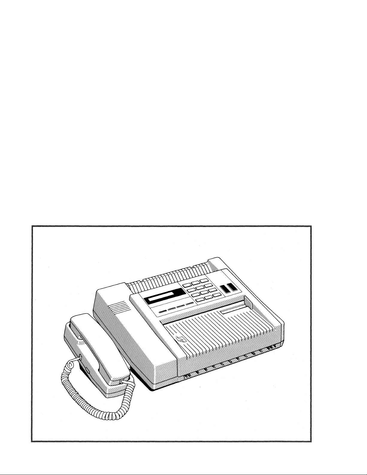
The Brother FAX-210 is a modern, compact desktop digital facsimile unit with such features as a
five (5) page automatic document feeder, an easy-to-read 16 character Liquid Crystal Display
(LCD), a paper cutter and an exclusive Electronic COVERPAGE™ feature. Its performance is
compatible with CCITT Group 3. Therefore, your new FAX-210 is compatible with most modern
facsimile units in the world.
The FAX-210 is an ideal low-volume stand-alone unit or a satellite unit in a larger facsimile network.
Furthermore, the unit can be used as a convenience copier and as a sophisticated business tele
phone.
All of the Brother FAX-210 features can be easily learned by following step-by-step procedures
listed on the following pages. As you become familiar with the features and operation of the
unit, keep the Owner's Manual handy for quick references and reminders.
The Owner's Manual provides a step-by-step description of the procedures you should employ
in unpacking, installing and learning to operate your Brother FAX-210 facsimile unit. If you
follow these instructions, you will have no problem with either the installation or the operation
of the unit.
Modern digital facsimile units are extremely reliable. If you exercise the necessary care, you will
enjoy years of totally trouble-free enjoyment of this unit.
Now, open the Owner's Manual to PRE-INSTALLATION INSTRUCTIONS (page 2) and read
the material carefully.
IMPORTANT NOTE
If you wish to start using your FAX-210 immediately upon purchase, you can learn
how to install it, use it as a transmitter or a receiver in a matter of minutes. To do so,
read the following material only:
• PRE-INSTALLATION INSTRUCTIONS
• GETTING FAMILIAR WITH THE UNIT
• BASIC OPERATIONS
After you read these pages, you will be able to send and receive facsimile commu
nications. Later, at your leisure, you can read the rest of the Owner's Manual and
learn how to benefit from the FAX-210's many other outstanding features.
Page 11
PRE-INSTALLATION INSTRUCTIONS
BEFORE REMOVING THE UNIT FROM THE CARTON
The Brother FAX-210 is designed to operate in an office environment or at home. It is rugged,
reliable and virtually maintenance-free. However, to ensure years of trouble-free performance,
please observe the following precautions:
Do not locate the unit near heaters, air conditioners, in direct sunlight or in dusty environments.
Install the unit on a flat level surface, such as a desk, a table, a typewriter or computer stand.
Do not locate the unit where water or chemicals are likely to splash on it.
Select a vibration-free area of your office.
Locate the unit within 3 feet from a telephone wall jack.
Locate the unit within 3 feet of a standard, grounded outlet.
Avoid plugging in the unit into an outlet which is on the same line as an air conditioner, a
refrigeration unit, a copier, an electric typewriter or any other device that draws a lot of current
Page 12

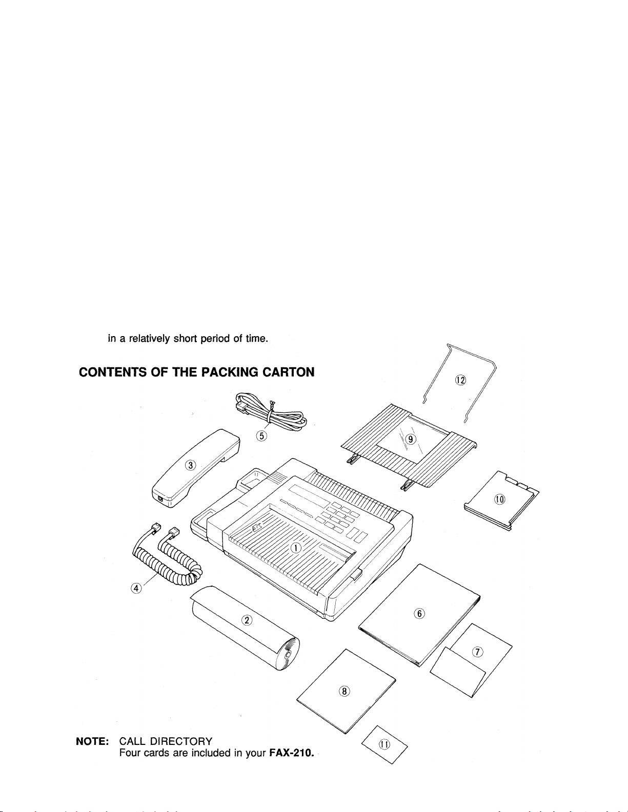
The packing carton contains:
(T) The Brother FAX-210 unit
(D One roll of Brother thermal recording paper
(D Telephone handset
(4) Handset curled cord
(f) Telephone line cord
(6) Owner's Manual
(7) Warranty card
(8) Test Sheet
(9) Original document tray
® Call Directory insert/Quick Reference Card
(n) Wallet Sized Card
® Wire Paper Holder
PROCEDURES FOR REMOVING THE UNIT FROM THE PACKING CARTON
1. Carefully open the carton (see the appropriate inscription on the carton)
2. Pull out the FAX-210 and the other devices together with the packing trays
3. Remove all packing trays and plastic from the unit
4. Take out the telephone line cord from the plastic packaging
5. Take out the telephone handset and the curled cord
6. Take out the paper roll
Page 13

INSTALLING THE UNIT
I. ELECTRICAL CONNECTION
The FAX-210 can be plugged into any standard power (110 VAC) outlet. Make sure that the
outlet is grounded and that it is not on the same iine as appliances or office machines which tend
to draw a iot of power in a very short period of time, such as refrigerators, copiers, etc. The
FAX-210 power requirements are listed in the SPECIFICATIONS.
After you plug in the power cord into the outiet, the LCD will display:
MSGCTR
PRESS STOP KEY
Press STOP. If you have not inserted the paper roll into the unit, "ADD PAPER" message
appears. If you have already inserted the paper roll, the unit is ready for use. The LCD will
display the date and time as foilows:
01/01/89 00:00
This LCD reading is referred to as the "standby mode" and it indicates that the unit is ready to
perform its functions. Later, we will show you how to set the date and time.
AUTO ANS
•PASSWORD
P_ MSG CTR
— AUTO ANS
"•-PASSWORD
NOTE: THE FAX-210 DOES NOT HA VE A POWER ON/OFF SWITCH.
II. SINGLE-LINE TELEPHONE CONNECTIONS
The FAX-210 must always be connected to the power outlet prior to making the telephone line
connection. Similarly, when disconnecting the unit, the telephone line connection should be
removed before unplugging the unit. This procedure is necessary because the unit relies on the
power outlet's ground for your protection from any possibly hazardous electrical conditions that
may arise on the telephone network.
The simplest way to connect the Brother FAX-210 unit to the public switched telephone
network (phone company lines) is to use a single telephone line. The connection is particuiarly
simple if you have a modular wall jack. The most common modular jack is referred to as the
USOC RJ11C jack. If you have such a jack, follow the instructions below. If your wall jack is
not modular. It is very easy to convert the wali piug to a modular form. Conversion is very
simple and conversion kits are avaiiable from your local phone company, an electronics /
computer store (e.g.. Radio Shack) or the AT&T phone stores.
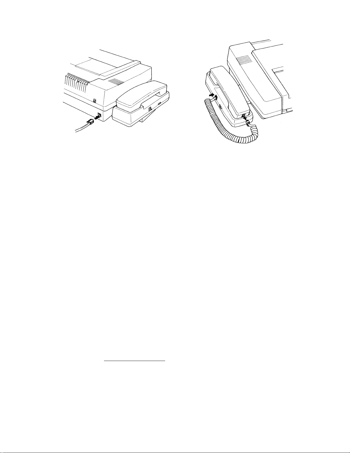
To connect your FAX-210 to the telephone line, foliow these steps:
• Connect one end of the curled handset cord to the handset and the second end to the RJ7
jack on the side of the handset cradle.
• Take the telephone cord which is also included in the carton and connect one of its plugs to the
LINE jack in the back of the FAX-210 unit and the second plug to your modular wall jack
(USOC RJ11C). Now, the FAX-210 is connected to the telephone network.
Please see the illustration on the next page for the telephone connections.
MODULAR PLUG
TO WALL OUTLET
Page 14
If you have MODULAR PHONE JACKS (USOC RJ11C), simply plug the phone cord into the
wall jack.
If you have the older 4-PRONG JACK, you must use a modular 4-prong adapter USOC RJA1X.
Plug the adapter into the wall jack and then plug the phone card into the adapter. Then, follow
the instructions above.
III. MULTI-LINE TELEPHONE CONNECTIONS
Most offices have key systems or PBXs. While in many cases it is relatively easy to connect the
FAX-210 to a key system or a PBX, we suggest that you contact the organization which
installed your company's telephone system and ask them to connect the FAX-210 to the
system. If the FAX-210 is connected to a key system, ask your installer to connect the FAX-
210 to the last line on the system. This way, the FAX-210 will not be activated by every phone
call coming into your office. The preferred solution is to ask the phone company to assign a
separate line to the facsimile unit. In this case, you can leave the unit on 24 hours a day and
derive full benefits from its automatic, unattended operations capabilities.
IV. INSERTING THE RECORDING PAPER ROLL INTO THE UNIT
To insert the paper roll, follow the directions given below. Before reading the instructions for
inserting the recording paper into the unit, please consider these important notes:
NOTE 1 : The recording paper is heat-sensitive. Avoid exposure to high temperature, high
humidity or direct sunlight. Keep the received documents (or copied documents)
away from high temperature, direct sunlight, high humidity, alcohol, blueprints.
Otherwise the documents may become discolored.
NOTE 2: The use of Brother Recording Paper is specifically recommended for this unit. The
use of paper not authorized by Brother may adversely affect the unit's performance
and may void Brother's product warranty.
Brother Recording Paper has a red stripe indicator. Its appearance on your received or copied
documents is a warning that the paper roll will be running out shortly. Replace the paper roll
when you see the red stripe. Furthermore, Brother Recording Paper has a black stripe at the
end of the roll. If you have not changed the paper at the appearance of the red stripe, the unit
will automatically stop when the black stripe appears. This feature works only with Brother
Recording Paper on Brother facsimile units. Please note that Brother Recording Paper rolls are
overwound (i.e., contain extra paper) so that you are not wasting paper when you remove the
roll when the indicator appears.
Page 15
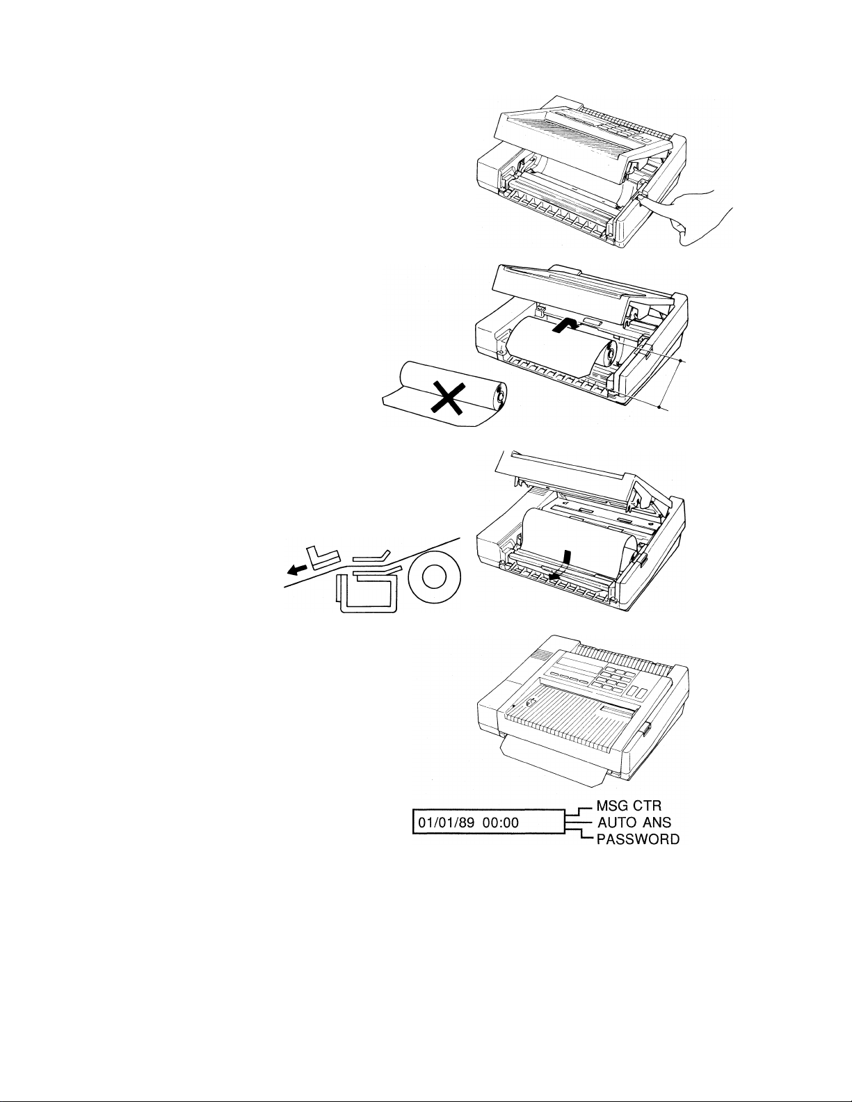
To insert the paper roll, follow these directions:
1. To open the paper cover, press the button
which is located at the right edge of the
top of the machine.
Hold the recording paper roll so that the
free end of the paper points towards you
from the top of the roil. Be sure not to
set the recording paper upside-down. If
this happens, you will not get any images
on reception or copying.
3. Drop in the paper into the unit. Place the
leading edge of the paper through the
paper cutter guide.
4. Push the cover unit until you hear a click.
5. Press STOP. The automatic cutter will cut
off excesspaper and the unit will go into
the standby mode (ready). The LCD will
change to:
6. If you forget to press STOP, the unit will
go into the standby mode as soon as
someone calls it.
Page 16

V. INSERTING THE ORIGINAL DOCUMENT TRAY
The original document tray consists of document tray, Call Directory and Quick-Reference Card,
and wire paper holder. The Call Directory Card and the Quick-Reference Card can be inserted
into the back side of the tray in the following step.
1. Turn the tray face down. Also hold the Call Directory Card and the QuickReference Card face down. Insert either left or right leg (positioned at the
bottom of the Cards) into the slit of the tray and then insert another leg. See
Illustration 1 below.
2. Slide the Cards down along the slits. Puts the upper part of the Cards below
the two protrusions coming out face to face at the top middle of the tray. (The
tray must still face down.) Slide the Cards down to the bottom of the slits.
3. Now turn the tray face up.
A wire paper holder also comes with this tray and can be easily installed into the tray. Locate
small holes at the top of the tray. Insert the legs of the paper holder into the holes. Make sure
the other end of the wire protrude upwards as shown below. Pre-installation is complete.
Insert the above tray into the slots at the top of the unit as shown in the Illustration 2 below.
Illustration 1
Illustration 2
Page 17
8
GETTING FAMILIAR WITH YOUR BROTHER FAX-210
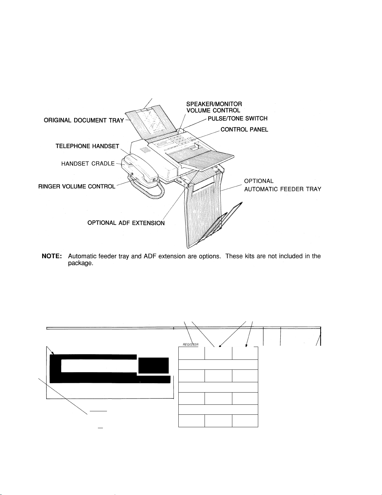
i. THE FAX-210-PARTS AND THEIR FUNCTIONS
Now that the unit is connected to the telephone network and the power, take a few minutes to
become familiar with the unit. The main parts of the unit and their functions are indicated in the
drawing below:
CALL DIRECTORY INSERT
LCD,
FUNCTION/
PAUSE
KEY
CONTROL
II. THE CONTROL PANEL
Now, let's take a look at the control panel of the Brother FAX-210. The layout of the control
panel is shown below. The purpose of the various buttons is described on the next page.
SPECIAL FUNCTION PAD
KtYb // STOP KEY
brother FAX-210
[function \ NEXT
HOOK ^ PAUSE REDIAL
HOOK
KEY
^ MSG CTR
— AUTO ANS
3 I I C D C
NEXT/REDIAL
KEY
PASSWORD
SET/MANUAL DIAL
1 \
4 GHI \
7 PRS
KEY
2 3 dee
\ v_
___________________________
s5
8 Tuv
^=3 t>
Q OPER
ß MNO
CO ^AG E MSG C TR
g wxY
U
STOP
COPY/START
KEY
□ MIC
Page 18

Operation of the control buttons and switches
START/COPY button
COPY
START
STOP button
STOP
TEN KEY PAD-
LCD -
- MSG CTR
- AUTO ANS
- PASSWORD
Initiates facsimile transmission or copy operation.
Stops any of confirming programming in the FUNCTION SETTING
mode.
Stops copying; stops document transmission (but cannot stop
reception or phone calls);
Stops continuous beeping in ERROR;
Confirms the elimination of abnormality (e.g., you press the STOP
button after you change the paper roll).
Initial function - one touch calling buttons (0 - 9).
Regular telephone dialing keys only after you press the MAN. DIAL
button for manual dialing.
Used for registering certain items into the unit (one-touch, speed-dial,
etc.)
The * and # keys control the cursor movement left and right,
respectively, during certain programming operations. # is also used
for speed dialing.
Displays date and time In the standby mode.
Displays prompts during programming and operational activities of the
unit.
Displays results of various operations and indicates problems/errors.
Up to 16 digits can be displayed at a time. When information contains
more than 16 digits, you can press the cursor key to scroll the display
(in the direction indicated by the cursor)
HOOK CONTROL -
Pressing this button allows dialing with the handset still in ON HOOK
status and activates the monitor so that the operation of the machine
may be heard. The monitoring sound will not be heard from the
speaker during dialing when you are in on-hook status.
HOOK
f 1 Pressing the HOOK button again in the ON-HOOK status turns off
the line.
Removing the handset from the cradle (off-hooking) while the HOOK
button is still engaged, stops the monitoring activity of the speaker
and allows you to make a phone call using the handset. During the
handset-originated telephone call, the HOOK button will not be
activated, even if pressed.
FUNCTION/ PAUSE -The FUNCTION button in programming (this is its initial and major usage).
\function\
PAUSE
The PAUSE button inserts a delay in the dialing process. This function
can operate only during:
- Manual dialing in automatic transmission mode
- Registration for programmed transmission.
When the PAUSE button is pressed, the LCD displays the letter "P".
Page 19

10
NEXT/REDIAL -
NEXT
REDIAL
1 I
NEXT is a registration/setting button in programming.
Pressing the REDIAL button redials a destination for which dialing has
already been attempted once (allows the redialing of the previously
dialed number). The LCD will display the telephone/fax number being
dialed :
- MSG CTR
TEL: 516P555P1212
(when using the unit as a telephone in non-auto-dial mode, press the
~ AUTO ANS
-PASSWORD
MAN. DIAL button - see below).
Pressing the REDIAL button causes the LCD to display the called
number again.
NOTE: If the power is turned off, the REDIAL memory of the
previously dialed number is lost. With the power ON,
pressing the REDIAL button before any telephone number
has been dialed, will cause the LCD to display:
MSG CTR
REDIAL INVALID
— AUTO ANS
PASSWORD
SET/MANUAL DIAL -
SET
MAN.DIAL
Allows to dial telephone/fax numbers manually. Use for numbers not
stored in the unit's station memory.
SET is a registration button used during programming.
NOTE: The upper row of buttons - FUNCTION, NEXT, SET are shown in italics. More expianation
on the proper use of the above controi buttons wiii be provided in the body of this Manuai in
the appropriate pieces.
Other controls:
TONE/PULSE -
PULSE^ TONE
SPEAKER VOLUME -
SPEAKER VOL
RINGER VOLUME-
RINGER VOL
Located on the back of the unit. Allows you to set rotary or touchtone dialing.
Located on the back of the unit. This rotary control allows you to
adjust the volume of the monitor/speaker.
Located on the side of handset cradle, this control adjusts the
loudness of the ringing.
H L OFF
Page 20

11
BASIC OPERATIONS
I. THE COPY MODE
The easiest way to learn the FAX-210 is to begin with the COPY MODE. To make a copy,
follow the simple instructions below:
1.
2.
3.
4.
NOTE 1
NOTE 2
NOTE 3
Make sure the unit is plugged in and that the LCD is in the standby mode
Insert the document you wish to copy into the guide of the unit, face DOWN.
The LCD will display:
FAX/COPY READY
Press START/COPY.
When the unit completes copying the document, the original will be completely
free of the unit. The copy will be cut automatically.
FINE resolution is set automatically while the FAX-210 is functioning as a copier.
Warnings related to copying are on page 17.
If you wish to make a copy in PHOTO mode, choose PHOTO in the TEMPORARY
SETTING MODE (see p. 43).
II. HOW TO TRANSMIT DOCUMENTS
A. Preparing to transmit documents
^ MSG CTR
— AUTO ANS
^PASSWORD
You can start using the unit once it is plugged in, connected to the telephone network, has
paper inside of it and the LCD is in the standby mode. If you are satisfied with the factory
settings for various parameters (and, most of the users hardly ever have to change these
settings), you can start using the machine immediately.
Basically, the only difference between transmission and copying is that for transmission
you must dial a telephone number before pressing the START/COPY button!
The only programing most users do is to set the date and time and to program their fax number
and name so that they appear on the received document. All other programming can be postponed
for when you need some specific capability.
Also, bear in mind that the FAX-210 has an LCD which will display helpful prompts.
Furthermore, you can abort sending a document by pressing the STOP button.
Page 21

12
B. Transmitting documents
Now, you are ready to transmit your document. The exact procedure for transmission depends
on your selection of one of these methods:
• Manual dialing
• One-touch dialing
• Speed dialing
Any of these methods can be used with manual transmission or automatic transmission. If you
use automatic transmission, the unit will feed your document before dialing, and will send in quick
mode. It is a manual transmission if you first pick up the handset or press the HOOK button
and then dial (either manual dialing, one-touch dialing or speed dialing). If you use one-touch dial
or speed dial and then press the START button, this is an automatic transmission.
1. One-touch dialing
The procedure for setting up one-touch numbers (up to 10 of them) is described in the PROGRAMMING
THE UNIT section of the Manual. The actual transmission procedure is :
a) Manual transmission
• Insert up to 5 documents into the feeder face down. The LCD shows:
MSG CTR
FAX/COPY READY
— AUTO ANS
^PASSWORD
Press HOOK or pick up the handset. The LCD shows:
MSG CTR
FAX:
Press the desired one-touch number using the ten key pad. If you have already registered
the receiver's company name, the LCD shows the receiver's ID:
FAX:BROTHER INDU
If you have not registered the receiver's company name, the LCD shows the registered
receiver's facsimile telephone number:
FAX:052P263P583
The unit will start dialing automatically.
When you hear the fax tone, press START. A completion tone will sound for one second
after the transmission is completed. The LCD will revert to the standby mode.
01/01/89 00:00
— AUTO ANS
^PASSWORD
- MSG CTR
- AUTO ANS
-PASSWORD
- MSG CTR
- AUTO ANS
-PASSWORD
- MSG CTR
- AUTO ANS
-PASSWORD
b) Automatic transmission
• Insert up to 5 documents Into the feeder face down. The LCD shows:
- MSG CTR
FAX/COPY READY
- AUTO ANS
-PASSWORD
Page 22

Press the desired one-touch number using the ten key pad. If you have already registered
the receiver's company name, the LCD shows the receiver's iD:
If you have not registered the receiver's company name, the LCD shows the registered
receiver's facsimile telephone number:
Press START. The unit will start feeding a document and then start dialing, and initiate the
transmission automatically. A completion tone will sound for one second after the
transmission is completed. The LCD will revert to the standby mode.
2. Speed-dialing
a) Manual transmission
FAX:BROTHER INDU
FAX:052P263P583
01/01/89 00:00
13
- MSG CTR
- AUTO ANS
-PASSWORD
MSG CTR
— AUTO ANS
’-PASSWORD
r- MSG CTR
— AUTO ANS
’-PASSWORD
• Insert up to 5 documents into the feeder face down. The LCD shows:
MSG CTR
FAX/COPY READY
Press HOOK or pick up the handset. The LCD shows:
FAX:
Press # and the desired 2-digit code using the ten key pad.
Example: If 03 stands for 201 981 0300, press "#", "0",and "3", and the unit will dial
201 981 0300. The LCD shows:
FAX:#03
After one second, if you have already registered the receiver's company name, the LCD
shows the receiver's ID:
FAX:BROTHER INTE
If you have not registered the receiver's company name, the LCD shows the registered
receiver's facsimile telephone number:
— AUTO ANS
’-PASSWORD
MSG CTR
— AUTO ANS
’-PASSWORD
f_ MSG CTR
— AUTO ANS
’-PASSWORD
- MSG CTR
- AUTO ANS
-PASSWORD
FAX:201 P981P0300
- MSG CTR
- AUTO ANS
-PASSWORD
Page 23

14
The unit will start dialing automatically.
When you hear the fax tone, press START. A completion tone will sound for one second
after the transmission is completed. The LCD will revert to the standby mode.
I- MSG CTR
01/01/89 00:00
b) Automatic transmission
• Insert up to 5 documents into the feeder face down. The LCD shows:
FAX/COPY READY
Press # and the desired 2-digit code using the ten key pad.
Example: If 03 stands for 201 981 0300, press "#", "0",and "3", and the unit will dial
201 981 0300. The LCD shows:
FAX:#03
After one second, if you have already registered the receiver's company name, the LCD
shows the receiver's ID:
— AUTO ANS
"^PASSWORD
P- MSG CTR
— AUTO ANS
■^PASSWORD
- MSG CTR
- AUTO ANS
-PASSWORD
- MSG CTR
FAX:BROTHER INTE
If you have not registered the receiver's company name, the LCD shows the registered
receiver's facsimile telephone number:
FAX:201 P981P0300
Press START. The unit will start feeding a document and then start dialing, and initiate the
transmission automatically. A completion tone will sound for one second after the
transmission is completed. The LCD will revert to the standby mode.
01/01/89 00:00
- AUTO ANS
-PASSWORD
- MSG CTR
- AUTO ANS
-PASSWORD
- MSG CTR
- AUTO ANS
-PASSWORD
3. Manual dialing
a) Manual transmission
• Insert up to 5 documents into the feeder face down. The LCD shows:
- MSG CTR
FAX/COPY READY
- AUTO ANS
-PASSWORD
Press HOOK or pick up the handset. The LCD shows:
- MSG CTR
FAX:
- AUTO ANS
-PASSWORD
Page 24

15
Press MAN.DiAL. Dial the desired number using the ten key pad.
,-MSGCTR
FAX:201981030
If your desired number is more than 11 digits, the display will scroll, e.g.:
— AUTO ANS
"^PASSWORD
AX:201981030012
When you hear the fax tone, press START. A completion tone will sound for one second
after the transmission is completed. The LCD will revert to the standby mode:
01/01/89 00:00
MSG CTR
— AUTO ANS
PASSWORD
r- MSG CTR
— AUTO ANS
''-PASSWORD
b) Automatic transmission
• Insert up to 5 documents into the feeder face down. The LCD shows:
P- MSG CTR
FAX/COPY READY
Press MAN.DIAL. Dial the desired number using the ten key pad.
FAX:201P981P030
If your desired number is more than 11 digits, the display will scroll, e.g.:
AX:201P981P0300
Press START. The unit will start feeding a document and then start dialing, and initiate the
transmission automatically. A completion tone will sound for one second after the
transmission is completed. The LCD will revert to the standby mode.
— AUTO ANS
''-PASSWORD
P- MSG CTR
— AUTO ANS
'-PASSWORD
P- MSG CTR
— AUTO ANS
1-PASSWORD
P- MSG CTR
01/01/89 00:00
— AUTO ANS
'-PASSWORD
4. Redial button
When the telephone number was dialed, the telephone number dialed will be registered in
REDIAL button automatically.
If the number is busy in Automatic transmission, set the document in the feeder again.
Document will remain in the feeder in case of Manual transmission. Press HOOK or pick up the
handset and then press REDIAL. The unit will redial the last number dialed. After hearing fax
tone, press START.
Page 25

16
III. HOW TO RECEIVE DOCUMENTS
There are two methods for receiving documents with your FAX-210 unit:
• Automatic Reception
• Manual Reception
NOTE: If a telephone connected in parallel with the unit is used during receipt of a document, the
received document may include distorted characters.
A. Automatic Reception
The factory setting is for AUTO. ANSWER to be ON and for the unit to pick up the reception on the
first ring. Therefore, if you are satisfied with this setting, there is absolutely nothing you have to do
to receive documents automatically, except to make sure that the unit is plugged in and that there is
enough recording paper in the unit.
If for some reason you prefer for the unit to pick up automatically on the fourth (4) ring, you can
reprogram the AUTO. ANSWER function using the simple procedure described in the PROGRAMMING
THE UNIT section of the Manual.
Usually, the reason for this is as follows. The fax unit is on your desk and you can pick up the phone
before the unit has rung four times. If you hear a voice, you simply answer the caller. If you hear fax
tones, you can receive the document manually (see below). Of course, you can leave the handset onhook and press HOOK. Then you will hear the rings and the voice or fax tones over the monitor. If
you hear fax tones, press START.
B. Manual Reception
To switch the unit to the MANUAL RECEPTION mode, you have to turn off the AUTO ANSWER
mode. This is done by following the simple instructions on page 27.
When you hear a ring, pick up the handset and, if you hear a voice, start the conversation. If
you hear fax tones, press START.
NOTE: Do not leave the document in the feeder when the unit is set to Manual reception mode.
The unit can not receive document.
Page 26

17
IMPORTANT TRANSMISSION INFORMATION:
When inserting documents into the feeder hold the documents by both hands. Take your hands
off documents immediately once the first page of the documents has started to be fed into the
feeder.
Do not transmit or copy very thick pages (over 0.12mm thick). If you have to transmit such
pages, use a photocopier (not the FAX-210) to make a copy and transmit the copy instead.
Do not transmit or copy wrinkled, wet, or coated documents. Make a photocopy and transmit
it instead.
Do not transmit or copy documents printed on thick photographic paper, metal or textiles.
Make a photocopy and transmit it instead.
Do not transmit or copy documents that are too thin (tissue paper, tracing paper, etc.) The
thinnest paper suitable for transmission is 0.055mm. Make a photocopy and transmit it instead.
Remove all staples and paper clips from the documents to be transmitted.
Do not transmit or copy documents held together by scotch tape. Photocopy them and
transmit the photocopy.
Do not load the feeder with more than five (5) documents at a time.
Transmit carrier sheets and glossy papers one at a time.
Do not transmit documents of different sizes and/or thickness together.
When transmitting more than one document at a time using the ADF, make sure that they are
between 0.06 and 0.09mm thick. Otherwise, transmit one by one, or use a photocopier to
make copies and transmit them instead.
Scannable area that can be guaranteed is the shaded area in the following picture
208 (mm)
Document Length
USING THE UNIT AS A TELEPHONE
To use this unit as a telephone, you have the following choices:
• Manual dialing
• One-touch dialing
• Speed-dialing
All of these can be made in the ON-HOOK or OFF-HOOK mode. To use the three ways of
dialing, follow the same instructions as for facsimile dialing, except you do not set a document
into the feeder.
And the REDIAL function is also available.
Page 27

18
PROGRAMMING THE UNIT
THE FAX-210 has many capabilities. These can be programmed by the user. The method for
programming these will be described when we address a specific capability. Here, we will address a
number of fundamental operations.
Important: Perform all programming operations without a document in the feeder.
I. SETTING THE DATE AND TIME
The date and time display is referred to as the standby mode of the LCD. When in this mode, the
LCD initially displays:
_ MSG CTR
MM/DD/YY HH:MM
The initial factory setting date and time is "01/01/89 00:00".
This will change to the actual date and time after you complete the steps below.
• Press FUNCTION. The unit will go into the FUNCTION mode and the LCD will
display:
FUNCTION(0-9)?
- AUTO ANS
*-PASSWORD
_ MSG CTR
-AUTO ANS
^PASSWORD
Press "6". The LCD will revert to the standby setting, except that there will be a
cursor under the first "M". Input the correct 2-digit number for the month (from 01
to 12). As the month is completed, the cursor will move to the first "D" where you
input the correct number for the day (01 to 31). Continue this process until the entire
date and time is registered. Note that this unit uses the 24 hour clock, i.e., 9:15PM is
shown as 21:15.
Press SET twice. From this point on, the standby mode of the LCD will display the
correct date and time.
II. REGISTERING YOUR FAX TELEPHONE NUMBER ID
Your fax unit's telephone ID number is used as an RTI/TTI number to identify your messages at
the remote location. When programmed, the number may be printed on documents received at
the distant end. It may also appear on their LCD display or transaction journals if these are
features of their equipment. You can register your telephone number up to 22 digits at a time,
all 22 digits can be seen by scrolling the LCD by using the cursor keys.
• Start by putting the unit into the FUNCTION mode (see above). Press "1" and the
unit will go into the REGISTRATION & SETTING mode and the LCD will display:
MSG CTR
REGISTER(0-9)?
Press "1". If there is no other number registered, the LCD will display:
FAX:_
— AUTO ANS
"^PASSWORD
r_ MSG CTR
— AUTO ANS
PASSWORD
Page 28

19
Input the appropriate numbers by using the ten key pad. As you press a number, the
digit appears at the current position of the cursor. If you wish to input a space, press
the right cursor key and the cursor moves to the next position.
When the input for fax telephone number ID has been completed, pressing NEXT will
bring you to the COMPANY NAME/DESTINATION NAME registration. And if you do
not touch any key for around 10 seconds after you have entered your fax telephone
number ID, it will be automatically registered and the LCD will revert to the standby
mode.
Clearing a Registered RTI/TTI number
• To clear the RTI/TTI number, bring the number up on the LCD again.
f- MSG CTR
FAX:2 01 111 5881
• Make sure that the cursor is under the first digit of the number, and press PAUSE
three times. The LCD shows;
FAX:_
— AUTO ANS
PASSWORD
I- MSG CTR
— AUTO ANS
''-PASSWORD
Correcting Mis-registration
• To correct an incorrect number, you can overwrite the registration, but cannot insert a
number into it. For example, if you input "201 311 5881" for "201 111 5881",
bring the cursor to "3". Enter "1".
MSG CTR
FAX: 201 1
Anything to the right of the cursor will be erased.
NOTE: You may use the PAUSE button to insert a pause, yet this inputs a "P". Then your
RTI/TTI number will appear like 201 P111P5881 both on the display and in print. If you
do not like this, use the cursor right key to insert a space as mentioned above.
AUTO ANS
•PASSWORD
Page 29

20
III. REGISTERING YOUR COMPANY NAME/DESTINATION NAME
You can register up to 22 (twenty two) alphanumeric characters for your company name/ID.
• Press NEXT after you've registered the RTI/TTI. The LCD displays:
MSG CTR
NAME:
• Input is accomplished by using the character chart on the next page. Please note that
you must use the 2-digit code for each alpha or numerical character in your station
ID.
• When the input for the STATION ID has been completed, pressing NEXT will return
you to the RTI/TTI setting. And if you do not touch any key for around 10 seconds
after you have entered your STATION ID, it will be automatically registered and the
LCD will revert to the standby mode.
NOTE: If you have not registered the RTI/TTI number, you cannot register your company
name/ID.
Clearing a Registered Company Name/Destination Name
• To clear a company name/destination name, bring the name up on the LCD again:
— AUTO ANS
^PASSWORD
MSG CTR
NAME:fiROTHER
Enter the 2-digit code for a blank (0,0) using the ten key pad. This erases the
registration entirely. The LCD shows:
NAME:
— AUTO ANS
^PASSWORD
MSG CTR
— AUTO ANS
PASSWORD
Correcting Mis-registration
• To change a character already registered, move the cursor under the character to be
changed, then overwrite the character with the correct 2-digit code. For example, if
you input BRATHER instead of BROTHER, bring the cursor to "A" and enter the 2digit code for "O". The correction will be shown on the display.
• To correct a missing character, move the cursor to the place where the character is
missing and put in the 2-digit code for the missing character. Then reinput all
characters succeeding the missing character. For example, if you entered BRTHER
and forgot the "O", move cursor under the "T" then input the 2-digit code for "O", T',
"H", "E" and "R".
Please see the chart on the following page.
Page 30

21
CHARACTER CODE CHART
BLANK
00
J
01
( )
08
0
16
8
24 25 26
@
32
H
09 10
1 2
17
9
A B
33
1
If
02
#
03
+
11 12 13
3
18 19 20
■
■
■
27
c
34
J
35 36
K L M
$
04 05
3
%
—
4 5 6
21
<
28 29
=
D E
37 38 39
&
06 07
-
14
/
15
7
22
>
30 31
F
N
23
?
G
0
1
40
P
48 49 50 51
X Y z
56
Example: BROTHER = 34, 50, 47, 52, 40, 37, 50 Example: 201 = 18,16,17
41 42 43 44 45
Q
57
R s
58
[
59
T
52
Not
used
60
u
53
1
61
46 47
V
54
A
62
w
55
—
63
Page 31

22
IV. SETTING UP THE AUTO DIALER
A. Registering One-Touch Numbers
You can register ten (10) one-touch numbers (up to 22 digits each) and destination names (up
to 20 characters each) for convenient dialing.
1.
2. Press "3". The LCD will display:
3.
4. Use the numeric ten key pad to enter the appropriate telephone number, e.g.:
5. Use PAUSE to register a pause for PBX or overseas transmissions.
Press FUNCTION and "1". Now you are in the REGISTRATION & SETTING
mode.
___________________
REGISTER(0-9)? — AUTO ANS
FXa:
Select a digit from 0 to 9 under which you will register the one-touch number
For example, press "1". The cursor will move to the next digit of
FX1:
FX1:201
FX1:201P
, r-MSGCTR
PASSWORD
MSG CTR
AUTO ANS
•PASSWORD
r- MSG CTR
— AUTO ANS
^PASSWORD
p. MSG CTR
— AUTO ANS
^PASSWORD
r- MSG CTR
— AUTO ANS
^PASSWORD
6.
7.
8.
If you try to enter a telephone number of more than 11 digits, the display will
scroll to the left.
- MSG CTR
X1:201P981P0300_
If you wish to add a destination name (up to 20 characters), follow the
instructions in Step 8.
Otherwise, if you do not touch any key for around 10 seconds, the one-touch
number will be registered automatically and the LCD will revert to the standby
mode.
Press NEXT. This registers the fax (telephone) number, and now you can
register the name attached to the one-touch number. The LCD will show:
NAME:
Use the chart on page 21 to input up to 20 characters.
- AUTO ANS
-PASSWORD
. MSG CTR
AUTO ANS
•PASSWORD
Page 32

23
9. To continue one-touch dial registration, press NEXT. The destination name is
registered, and the LCD will show
- MSG CTR
FX1:201P981P0300
10. Select another digit, for example, 2.
FX2:
11. Repeat the steps 4-8.
B. Registering Speed-Diaiing Numbers
Speed-dialing numbers are registered in the same manner, except you press "4" in the
REGISTRATION/SETTING mode. The display will allow you to input a 2-digit code (from 01 to 10 for
each of the ten (10) speed-dial numbers. The destination is registered in the same manner as above
using the chart on page 21.
For your convenience, you can record the one-touch and speed dial numbers on the Call Directory
sheet, which can be inserted into the Original Document Tray.
- AUTO ANS
-PASSWORD
. MSG CTR
AUTO ANS
•PASSWORD
Page 33

24
V. SETTING USER SWITCHES
User Switches control a number of key parameters of the unit's operation, such as: Resolution,
Contrast, Audio Beeper, Transmit Report, Password Transmission, Automatic Answer and the
Number of Rings on which the unit will answer automatically.
Press "7" in the FUNCTION mode. The unit enters USER SWITCH SELECTION
MODE. The LCD will display:
MSG CTR
USER SW(0-9)? — AUTO ANS
^-PASSWORD
Pressing 1, 2, 3, 5, 6, 7,9 (4, 8, 0 are not used) will allow you to set the User Switches.
To revert to standby mode from USER SWITCH SELECTION MODE, press SET twice.
A. Setting the Resolution
1. Press "1" in the USER SWITCH SELECTION MODE. The LCD will display:
MSG CTR
RES: STD
— AUTO ANS
^PASSWORD
2. Use STANDARD to transmit typewritten or printed materials. Use FINE for
detailed drawings or detailed text. Use PHOTO when you need to transmit an
image with many shades, such as a photograph, a colored original, etc. Please
note that the transmission speed is highest at STANDARD resolution, slower at
FINE and quite slow in PHOTO. Thus, use PHOTO only when warranted.
NOTE: The factory setting is STANDARD resolution.
3. Select the RESOLUTION mode using the cursor keys. Choose from the
following displayed RESOLUTION modes:
MSG CTR
RES: STD
RES: FINE
RES: PHOTO
4. If you press SET , the resolution is selected and the display returns to the USER
SWITCH SELECTION MODE.
If you press NEXT, the resolution is selected and the display proceeds to the
next user switch (SET THE CONTRAST).
If you press STOP, the display returns to the standby mode without
registration.
— AUTO ANS
^PASSWORD
. MSG CTR
AUTO ANS
■PASSWORD
. MSG CTR
AUTO ANS
■PASSWORD
Page 34

B. Setting the Contrast
1. Press "2" in the USER SWITCH SELECTION MODE. The LCD will display:
25
CONTRASTiNORMAL
- MSG CTR
- AUTO ANS
■-PASSWORD
2. Select the contrast based on the contrast of the original document. That is, if
3. Select the CONTRAST setting using the cursor keys.
4. If you press SET , the contrast is selected and the display returns to the USER
NOTE 1: When RESOLUTION is set to STD (standard), CONTRAST is automatically
NOTE 2: When RESOLUTION is set to PHOTO, CONTRAST cannot be controlled as
the document is light, select the LIGHT setting, if the original is dark, select the
DARK setting. Otherwise, leave the unit in the factory setting position NORMAL.
SWITCH SELECTION MODE.
If you press NEXT, the contrast is selected and the display proceeds to the next
user switch (TURN AUDIO BEEPER ON or OFF).
If you press STOP, the display returns to the standby mode without
registration.
controlled.
above.
C. Turning the Audio Beeper On or Off
1. Press "3’' in the USER SWITCH SELECTION MODE. The LCD will display:
BEEPER:ON
2.
3.
Select the ON or OFF setting using the cursor keys
If you press SET , the AUDIO BEEPER ON or OFF is selected and the display
returns to the USER SWITCH SELECTION MODE.
If you press NEXT, the the AUDIO BEEPER ON or OFF is selected and the
display proceeds to the next user switch (SELECT XMT VERIFICATION
REPORT ON OR OFF).
If you press STOP, the display returns to the standby mode without
registration.
MSG CTR
— AUTO ANS
■PASSWORD
D. Turning the transmit report function On or Off
To activate the XMT varification report, follow these steps:
1. Press "5" in the USER SWITCH SELECTION MODE. The LCD will display
r- MSG CTR
XMT VERIFY:OFF
■PASSWORD
2.
3.
Select the ON or OFF setting using the cursor keys
If you press SET, the transmit report function (XMT VERIFICATION) ON or
OFF is selected and the display returns to the USER SWITCH SELECTION
MODE.
If you press NEXT, the transmit report function (XMT VERIFICATION) ON or
OFF Is selected and the display proceeds to the next user switch (SELECT
PASSWORD TRANSMISSION MODE).
If you press STOP, the display returns to the standby mode without
registration.
AUTO ANS
Page 35

26
*****************************
*
★
*
*
DESTINATION
MODE
PAGE(S)
RESULT
XMT VERIFICATION MM/DDA'Y HH:MM
: 01
*******************************************
BROTHER INDUSTRIES
G3 STANDARD
OK
BROTHER FAX-210
*****************************
NOTE 1: Only when the transmit report function (XMT VERIFICATION) is set to ON
and your document was properly transmitted, the unit prints out the above
report.
NOTE 2: If a communication error occurred, a communication error report (see p. 53)
is always printed out whether the transmit report function is ON or OFF.
NOTE 3: If the line was busy and your document was not transmitted, neither the
above report nor a communication error report is printed out.
E. Selecting the Password Transmission mode
NOTE: The FAX PASSWORD (refer page 48 SETTING THE FAX PASSWORD) permits
transmission to you by units with the same matching pass-code. Use this feature if you
are part of a closed network or if fax "junk mail" is a problem. Registration of the
passcode is described in ADVANCED OPERATIONS below.
*
*
*
*
1. Press "6" in the USER SWITCH SELECTION MODE. The LCD will display:
MSG CTR
PASSWORDrOFF
— AUTO ANS
"•-PASSWORD
2.
Select the ON or OFF mode using the cursor keys.
P- MSG CTR
PASSWORD:ON
— AUTO ANS
"•-PASSWORD
3. If you press SET, the PASSWORD TRANSMISSION MODE is selected and the
display returns to the USER SWITCH SELECTION MODE.
If you press NEXT, the PASSWORD TRANSMISSION MODE is selected and
the display proceeds to the next user switch (SELECT AUTO ANSWER &
NUMBER OF RINGS).
If you press STOP, the display returns to the standby mode without
registration.
If you have set Password into ON position, the LCD shows at the proper position in
standby mode.
MSG CTR
01/01/89 00:00
— AUTO ANS
"•-PASSWORD
Important: Unless necessary, leave the Password Transmission OFF to permit communication with non-Brother units.
Page 36

27
F. Selecting the Auto Answer & Number of Rings mode
1. Press "7" in the USER SWITCH SELECTION MODE. The LCD will display:
MSG CTR
AUTO ANS.-1
You can set the Automatic Answer to ON or OFF and in the ON position, you
can have the unit answer on 1 ring or 4 rings.
"AUTO ANS:1" means the unit answers on the first ring.
2. Make your seiections using the cursor keys.
3. If you press SET, the Auto Answer & Number of Rings are selected and the
display returns to the USER SWITCH SELECTION MODE.
If you press NEXT, the Auto Answer & Number of Rings are seiected and the
dispiay proceed to the next user switch (SELECT MESSAGE CENTER ON OR
OFF).
If you press STOP, the display returns to the standby mode without
registration.
If you have set the Auto Answer into ON position (1 ring or 4 rings), the LCD shows
at the proper position in standby mode.
— AUTO ANS
^PASSWORD
01/01/89 00:00
MSG CTR
— AUTO ANS
^PASSWORD
Page 37

28
VI. THE MESSAGE CENTER
The built-in Message Center in your FAX-210 allows you to utilize both telephone answering and
facsimile capabilities on a single telephone line. Callers can even leave a voice and fax message
on the same call!
The Message Center has many features and capabilities, some of which can be found only on
expensive answering machines. These features and capabilities include:
• Digital storage of incoming and outgoing messages
• User-recordable outgoing message (OGM)
• Personal memo function
• Beeperless remote control
• Call screening capability
• Toll-Saver feature
• Remote voice-fax message control
• Auto Paging
A. Turning the Message Center ON
The MESSAGE CENTER MODE can be turned ON via User Switch setting. A reminder - to get
into the USER SWITCH SELECTION MODE, start with the FUNCTION MODE (no document in the
feeder, press FUNCTION), then press "7" to get into the USER SWITCH SELECTION MODE. Once
in that mode:
• Press "9". The LCD will display:
^ MSG CTR
MSG CTR:OFF
• Make your selection using the cursor. Press SET to set the selected mode.
IMPORTANT: MSG CTR cannot be turned ON unless the OGM has not been
recorded (see p. 33).
— AUTO ANS
^PASSWORD
• Press SET twice to revert to stanby mode.
• An indicator will also appear adjacent to the MSG CTR on the right side of the LCD
when the Message Center has been turned on.
B. Using the Message Center Functions
The FAX-210 allows you to perform a variety of programming activities to customize the
performance of the Message Center to your needs. These are described below in C.
Here, we will show you how easy it is to operate the Message Center.
NOTE: To activate the Message Center, the OGM (Outgoing Message) must be recorded
(see p.33).
Put the unit into the FUNCTION MODE (no document in the feeder and press
FUNCTION)
Press "9". The LCD will display one of the following:
• If messages are recorded, the LCD shows.
MSG CTR
MSG RECORDED
When messages are recorded and the memory for them is full, the LCD shows,
MSG FULL
— AUTO ANS
^PASSWORD
^ MSG CTR
AUTO ANS
■PASSWORD
Page 38

29
If there are no message recorded, the LCD shows,
MSG CTR
NO MESSAGE
Now, we will show you how to play back and erase incoming messages(i.e., messages which
were left on your unit by a caller via the telephone), and how to record, playback and erase
MEMOS, (i.e.,messages which were recorded on your unit via the built-in microphone).
1. ICM Playback Procedure
• Start with the LCD displaying:
MSG RECORDED
— AUTO ANS
‘‘-PASSWORD
MSG CTR
— AUTO ANS
‘‘-PASSWORD
or
MSG FULL
Press NEXT to initiate ICM (Incoming Message) playback. The LCD will display:
PLAY ERS FWD — AUTO ANS
With this LCD display, the three buttons under the display change their functions as
follows:
-------
1 PLAY (PLAY BACK)
PAUSE
-------
1 ERS (ERASE)
REDIAL
-
-----
1 FWD (FORWARD)
Therefore,
a. Press HOOK to play the message. You can repeat the same message by
pressing HOOK again.
Press PAUSE to erase a message while the message to be erased is being played
b.
back. This erases one entire message at a time. If you have cleared all messages,
press SET. The LCD will be:
NO MESSAGE
Press REDIAL to forward (skip to the next message). If there is no next
c.
message, the unit will finish piaying back.
To clear the Message Center memory of all incoming messages and MEMOs , press
. MSG CTR
AUTO ANS
•PASSWORD
r- MSG CTR
‘‘-PASSWORD
MSG CTR
— AUTO ANS
‘‘-PASSWORD
PAUSE and REDIAL simultaneously.
Then press SET. The LCD will change to,
MSG CTR
NO MESSAGE
Press SET to return to the original LCD display:
MSG RECORDED
— AUTO ANS
^PASSWORD
MSG CTR
— AUTO ANS
‘‘-PASSWORD
Page 39

Let's take an example.
Suppose that two ICMs came in while you were out.
Press FUNCTION and "9". The LCD shows,
Press NEXT. The LCD changes to:
Press PLAY (HOOK). The first message is heard from the monitor. If you leave the
unit as it is, the second message will follow. If you press PLAY again during the
playback of a message, the message will be repeated from the beginning.
To erase a message, press ERASE(PAUSE) during the playback of the message.
Pressing FORWARD stops the playback of a message, and skips to the next message.
2. The MEMO Function
MSG RECORDED
PLAY ERS FWD
30
MSG CTR
AUTO ANS
•PASSWORD
. MSG CTR
AUTO ANS
■PASSWORD
The MEMO function records messages directly through the built-in microphone. The
unit provides you with an ability to record a voice memo which can be used by you as a
memory-jogger or be accessed by a member of your family or co-worker when you are
out.
Start with the LCD displaying:
MSG CTR
AUTO ANS
■PASSWORD
or
Press NEXT. The LCD will display:
PLAY ERASE FWD
MSG CTR
AUTO ANS
■PASSWORD
, MSG CTR
AUTO ANS
■PASSWORD
If you wish to record a MEMO, press either cursor key. The LCD will display:
- MSG CTR
MEMO:RECORD
Press START/COPY. The unit enters the recording mode and the LCD will display:
- AUTO ANS
-PASSWORD
MEMO:RECORDING
- MSG CTR
- AUTO ANS
-PASSWORD
Page 40

31
Speak into the microphone. The iength of a MEMO is the same as ICM (see p.42)
When you have finished recording the MEMO, press STOP. The LCD displays:
_ MSG CTR
MEMO RECORDED
After 2 seconds, the LCD returns to:
MEMO:RECORD
Or if you do not press STOP after recording, after the selected MEMO (ICM) time
runs out, the display will automatically return to:
MEMO:RECORDED
• Press SET to return to the original LCD display:
MSG RECORDED
- AUTO ANS
■-PASSWORD
MSG CTR
AUTO ANS
•PASSWORD
- MSG CTR
- AUTO ANS
^PASSWORD
. MSG CTR
AUTO ANS
■PASSWORD
If you wish to play back MEMOs, press NEXT.
(3) choices:
PLAY ERS FWD
Press PLAY (HOOK) to playback MEMO's.
Let's take an example.
Suppose that you are in home and have an appointment at 6:00 with your husband. But you want to
change the time and cannot reach him now. In such a case, you can use the MEMO function. Your
husband can get your message recorded on your FAX-210 using the REMOTE OPERATION function
(see p.41) even if you are out.
Press FUNCTION, and select "9".
MSG FULL
This LCD display means that the memory is full and you have to erase ICM before recording your
MEMO.
Let's listen to ICMs first. Press NEXT.
PLAY ERS FWD
The LCD displays the following three
j_ MSG CTR
- AUTO ANS
"■-PASSWORD
- MSG CTR
- AUTO ANS
■-PASSWORD
_ MSG CTR
- AUTO ANS
■-PASSWORD
Press PLAY. You will hear the ICMs.
Suppose that you received three ICMs, and that you want your husband to listen to only the second
ICM and your MEMO. Then you have to erase the first and third ICMs. To do that, press PLAY
again. While the first ICM is played, press ERASE. And press ERASE during the third ICM.
Page 41

32
Now, you can record your MEMO for your husband. With the following display, press either cursor
key.
^ MSG CTR
PLAY ERS FWD
The display will change to.
MEMO:RECORD
Press START/COPY,
MEMO:RECORDING
Speak into the microphone for example, "Sorry, I will see you at 6:30". Please refer to p.42 for the
MEMO length.
When you finish, press STOP. The LCD will show.
— AUTO ANS
^PASSWORD
. MSG CTR
• AUTO ANS
■PASSWORD
- MSG CTR
- AUTO ANS
-PASSWORD
. MSG CTR
MEMO:RECORDED
After 2 seconds, the display will revert to:
MEMO:RECORD
If you want to check your MEMO, press either cursor key. The LCD will change to "PLAY ERS FWD",
and press PLAY. You will hear the second ICM and your MEMO. If it is OK, press SET. The LCD
will change.
MSG:RECORDED
To return to the standby mode, press SET twice.
If you do not have to check your MEMO, just press SET three times to return to the standby mode,
with the " MEMO:RECORD" display. .
Now, your husband can reach your MEMO using the REMOTE OPERATION function.
AUTO ANS
■PASSWORD
MSG CTR
AUTO ANS
■PASSWORD
r- MSG CTR
— AUTO ANS
PASSWORD
Page 42

33
C. Programming the Message Center and Recording the OGM
To program the Message Center, set the unit into the REGISTRATION & SETTING MODE by first
getting it into the FUNCTION MODE (no document in the feeder, press FUNCTION) and then
pressing "1".
While in the REGISTRATION & SETTING MODE:
• Press "9". The LCD will display a selection. Press the appropriate number:
r- MSG CTR
MSG CTR(1-8)? Er AUTO ANS
^-PASSWORD
pressed
1
2 NOT USED
3
4
5
6
7
8
This is what happens when you press an appropriate number. The numbers are shown in the left
column and the explanation of what happens is given to the right of the numbers. The first operation
must start with the LCD displaying:
Resultant chanae in the LCD
OGM TIME: 08
OGM: RECORD
ICM#:3
CALL MSG: RECORD
PAGING:OFF
MSG CTR CODE:fiO
CALLTEL:_ Registers Automatic Paging destination
r_ MSG CTR
MSG CTR(1-8)?
— AUTO ANS
^PASSWORD
Function
Qutgoing Message length selection
Recording of OGM
Number of Incoming Messages that
can be recorded
Automatic Paging Recording
Automatic Paging ON/OFF
Registers security code for Message
Center Remote Operation
telephone number
The subsequent operations can be started by using the NEXT key after completion of a
preceding operation.
To revert to the standby mode, press SET three times.
Page 43

34
£.
1
Outgoing Message length selection
The length for the Outgoing Message (OQM) is 8, 12 or 16 seconds. When you press
EXPLANATION
"1", the LCD displays:
r- MSG CTR
OGM TIME:08
Use the cursor keys to select the desired OGM length, i.e., 8, 12 or 16. Input by ten key
pad is nol accepted. The longer the OGM, the less time Is available for the
AUTO ANS
■PASSWORD
Incoming MessagesI
If you press NEXT, the OGM time selection will be registered and the LCD will prompt you to
the next function (see #2 below):
MSG CTR
OGM:RECORD
If you press SET instead of NEXT the selected OGM time will also be registered and the
LCD reverts to the original:
MSG CTR(1-8)? — AUTO ANS
— AUTO ANS
"•-PASSWORD
MSG CTR
PASSWORD
IMPORTANT: Time for OGM cannot be changed when any ICM/MEMO is
recorded.
Recording of OGM
When you press "3", the LCD gives you three choices which you select using the
cursor keys:
MSG CTR
OGM:RECORD
OGM:PLAY
OGM:ERASE
— AUTO ANS
"•-PASSWORD
MSG CTR
— AUTO ANS
^PASSWORD
MSG CTR
— AUTO ANS
^PASSWORD
NOTE: You can not select PLAY or ERASE if you have not recorded the OGM.
(a) When you are in the OGM RECORD mode.
Press START/COPY to record the OGM. The LCD will show:
MSG CTR
OGM:RECORDING — AUTO ANS
"•-PASSWORD
After recording, press STOP and the display will show:
f- MSG CTR
OGM:RECORDED
— AUTO ANS
"•-PASSWORD
Page 44

35
After 2 seconds, the LCD reverts to:
. MSG CTR
OGMiRECORD
NOTE: Even if you do NOT press STOP, your OGM will be recorded, and the LCD
will automatically revert to the above message when the selected OGM time
has run out.
If you wish to playback OGM, press the right cursor key.
OGMiPLAY
If you wish to go on to the next function (see #3 below), press NEXT. The LCD
displays:
ICM#:3
If you are satisfied with the recording, press SET. The LCD displays:
MSG CTR(1-8)?
(b) When you are in the OGM PLAY mode.
Press START/COPY to play the OGM. The LCD will show:
OGM:PLAYING
After listening, press STOP or after the selected OGM time is completed, the display
will revert to:
OGM:PLAY
If you wish to go on to the next function (see #3 below), press NEXT and the LCD
will display:
ICM#:3 — AUTO ANS
(c) When you are in the OGM ERASE mode.
Press START/COPY to erase the OGM. The LCD will show:
OGM:ERASED
After 2 seconds, the display will revert to:
OGM:RECORD
AUTO ANS
■PASSWORD
r- MSG CTR
AUTO ANS
■PASSWORD
MSG CTR
AUTO ANS
•PASSWORD
MSG CTR
— AUTO ANS
PASSWORD
p. MSG CTR
— AUTO ANS
PASSWORD
MSG CTR
— AUTO ANS
PASSWORD
MSG CTR
''-PASSWORD
. MSG CTR
AUTO ANS
■PASSWORD
. MSG CTR
AUTO ANS
■PASSWORD
Page 45

36
If you wish to go on to the next function, press NEXT and the LCD will display:
MSG CTR
ICM#:3
NOTE:
When the OGM is erased MSG CTR MODE (see p. 28) is automatically turned
OFF.
Number of Incoming Messages that can be recorded
Selecting the Incoming Message (ICM) number automatically determines the amount
of time available for each message. The more messages, the less time per message.
You have approximately 1 minute of OGM/ICM/MEMO capacity. This can be used for
1, 2 or 3 messages. Furthermore, the longer the Outgoing Message, the shorter the
total amount of time available for ICM (for instance, if you have a 16 second OGM,
you don't have a full minute for all of your ICMs, but only 43 seconds). The selection
of the numbers is done as follows:
If you are doing this before any of the above-described operations, you start with the
LCD displaying:
MSG CTR(1-8)?
Press "4". The LCD will display:
AUTO ANS
•PASSWORD
j- MSG CTR
— AUTO ANS
■L-PASSWORD
MSG CTR
ICM#:3
Use the cursor keys to select the number of ICMs, for instance:
ICM#:2
If you wish to go on to the next operation (see #4), press NEXT and the LCD will
display:
CALL MSG:RECORD
Pressing SET will register your selection and the LCD will revert to:
MSG CTR(1-8)?
— AUTO ANS
''-PASSWORD
f- MSG CTR
— AUTO ANS
''-PASSWORD
- MSG CTR
- AUTO ANS
-PASSWORD
- MSG CTR
- AUTO ANS
-PASSWORD
IMPORTANT: If you change the ICM number, OGM is automatically cleared.
Automatic Paging Recording
The Auto Page function is used as follows. Suppose you are away from your home or
office but are expecting an important call. All you have to do is to turn on the Auto
Page Function on your fax unit and register a telephone number at which you can be
reached. Once the Message Center of your unit records a telephone call, the unit will
call the registered number and when you pick up the phone you hear the CALL
MESSAGE. Thus, you'll know that there is a recorded message on your facsimile's
Message Center. In this step, we are showing you how to turn this function ON.
Page 46

37
You have to record CALL MESSAGE before you turn the Auto Page function ON.
The CALL MESSAGE is to inform you that you have received ICMs when you are
away from home or office.
You can record the CALL MESSAGE up to five (5) seconds.
Press "5". The LCD will display:
- MSG CTR
CALL MSG:RECORD
Using the cursor keys, you can select three (3) courses of action:
(a) Call Message RECORDING,
Here the LCD initially displays:
CALL MSG:RECORD
Pressing START/COPY puts the unit into a recording mode and the LCD displays:
MSG:RECORDING
A sample CALL MESSAGE is shown below:
"Could you get Mr. Mike Smith from Brother on the phone, please?"
- AUTO ANS
-PASSWORD
. MSG CTR
• AUTO ANS
■PASSWORD
MSG CTR
— AUTO ANS
‘‘-PASSWORD
After recording the message, press STOP. The LCD will display:
r- MSG CTR
MSG: RECORDED
• After 2 seconds, the LCD returns to:
CALL MSG:RECORD
Even if you do not press STOP, the LCD will automatically change to:
MSG: RECORDED
And after two seconds the LCD changes to
CALL MSG:RECORD
If you wish to go on to the next operation (see #5 below), press NEXT and the LCD
will display:
PAGING:OFF
Pressing SET will register your choice and the LCD will revert to:
MSG CTR(1-8)? AUTO ANS
(b) Call Message PLAYBACK,
- AUTO ANS
-PASSWORD
- MSG CTR
- AUTO ANS
-PASSWORD
- MSG CTR
AUTO ANS
■PASSWORD
. MSG CTR
AUTO ANS
■PASSWORD
MSG CTR
— AUTO ANS
PASSWORD
MSG CTR
■PASSWORD
Page 47

38
Here the LCD initially displays:
MSG CTR
CALL MSGrPLAY
Pressing START/COPY puts the unit into a playback mode and the LCD displays:
CALL MSG:PLAYING - AUTO ANS
After playing the message, press STOP or simply wait. The LCD will display:
CALL MSG:PLAY — AUTO ANS
If you wish to go on to the next operation (see #5 below), press NEXT and the LCD
will display:
PAGING:OFF
• Press SET and the LCD will revert to:
MSG CTR{1-8)?
(c) Call Message ERASE,
AUTO ANS
•PASSWORD
MSG CTR
-PASSWORD
- MSG CTR
''-PASSWORD
. MSG CTR
AUTO ANS
■PASSWORD
. MSG CTR
AUTO ANS
■PASSWORD
Here the LCD initially displays:
. MSG CTR
CALL MSG:ERASE
Pressing START/COPY puts the unit into an erase mode and the LCD displays:
CALL MSG:ERASED
Press STOP or simply wait 2 seconds. The LCD will display:
CALL MSG:RECORD
AUTO ANS
•PASSWORD
MSG CTR
- AUTO ANS
-PASSWORD
- MSG CTR
- AUTO ANS
-PASSWORD
NOTE: When the CALL MESSAGE is erased, the AUTO PAGE FUNCTION is automatically
turned OFF. If you are going to record a new CALL MESSAGE, be sure to turn ON
the Auto Paging again.
• If you wish to go on to the next operation (see #5 below), press NEXT and the LCD
will display:
MSG CTR
PAGING:OFF
• Press SET and the LCD will revert to:
MSG CTR(1-8)?
AUTO ANS
•PASSWORD
MSG CTR
AUTO ANS
•PASSWORD
Page 48

39
Automatic Paging ON/OFF
Now that the AUTO PAGE is turned ON, your unit wiil give you a call to inform that
there is a recorded phone call.
iMPORTANT: You have to program CALL TEL number before AUTO PAGiNG
setting (see below 7).
After you've accessed this function by pressing "6", the LCD will display:
MSG CTR
PAGING:OFF — AUTO ANS
^PASSWORD
• Use the cursor keys to turn this function ON. The LCD will display:
r- MSG CTR
PAGING:ON
If you wish to go on to the next operation (see #6 below), press NEXT and the LCD
will display:
MSG CTR CODE: fiO - AUTO ANS
Pressing SET instead of NEXT will register your choice and the LCD will revert to:
MSG CTR(1-8)? — AUTO ANS
Registering security code for Message Center Remote Operation
AUTO ANS
■PASSWORD
MSG CTR
-PASSWORD
- MSG CTR
PASSWORD
To help you register a security code, the LCD will display, either by pressing "7" in the
"MSG CTR (1 - 8)?" choice or after you've pressed NEXT in the previous operation:
- MSG CTR
MSG CTR CODE: QO
Enter an appropriate 2-digit code.
If you wish to go on to the next operation (see #7 below), press NEXT and the LCD
will display:
CALL TEL:
• Press SET and the LCD will revert to:
MSG CTR(1-8)?
- AUTO ANS
-PASSWORD
- MSG CTR
AUTO ANS
■PASSWORD
MSG CTR
AUTO ANS
■PASSWORD
Registering Automatic Paging destination telephone number
Either by pressing "8" in the MSG CTR (1 - 8)? mode or by pressing NEXT in
previous operation, get the LCD to display:
I- MSG CTR
CALL TEL: — AUTO ANS
^PASSWORD
This allows you to program the telephone number at which the unit can call you using
the AUTO PAGE function.
Page 49

40
Use the ten key pad to input the number (up to 22 digits).
If you wish to go back to the very first operation (see #1 above), press NEXT and the
LCD will display:
MSG CTR
OGM TIME:08
Press SET and the LCD will revert to:
MSG CTR(1-8)? Er AUTO ANS
D. The Message Center and the Auto-Receive Functions
If you have set both the Message Center and the AUTO ANSWER functions to OFF on your
FAX-210 and someone is calling your unit, the unit will, after 15 rings:
• Enter the MESSAGE CENTER ON MODE after 15 rings if the OGM is recorded and
the ICM is not full. The OGM will start after 15 rings. After completion of this call,
the unit will revert to its original status — MESSAGE CENTER OFF and AUTO
ANSWER OFF.
or
Enter the AUTO ANSWER mode if the OGM is not recorded or the ICM is full.
— AUTO ANS
^PASSWORD
MSG CTR
^-PASSWORD
E. Toll-Saver feature
This function works on the FAX-210 in the MESSAGE CENTER mode as follows. The
MESSAGE CENTER will answer your call on:
• 3 rings if there is no message - then, after 3 rings the OGM will go on. Thus, unless
you wish to record a message on your unit via the remote MESSAGE CENTER
feature, you can hang up before the 3rd ring and save the cost of a completed phone
call.
• 1 ring if there is a message or messages. The OGM will start after 1 ring and you can
use remote control procedures to pick up the message.
• 1 ring if the ICM is full. Then, after 1 ring. Auto Answer will go on.
F. Call Screening
You can screen the incoming call via the monitor and this allows you to answer the call after you
have known who is calling or, if it is a facsimile transmission (which you will know as soon as
you hear the fax tones), you can let the unit accept the facsimile transmission in either the
automatic or the manual modes (depending on your preference).
Page 50

41
G. Remote Operation of the Message Center
The messages recorded on your FAX-210 Message Center can be retrieved from any touchtone telephone, provided, you know the 2-digit security code. To do so, press "9" when you
hear the OGM (your Outgoing Message) or Call Message.
1. Dial the telephone number of your FAX-210 unit.
2. When you hear the OGM , press "9" repeatedly until you hear a short beep (1 second).
3. Dial in the 2-digit Security Code within 15 seconds of hearing the beep. If the code is
correct, you will hear a short beep (1 second). If the code is incorrect, you will hear a
series of short beeps. Try again!
Now, you are ready to request the FAX-210's Message Center to perform some functions.
These functions and the remote commands needed to activate them are shown in the table
below.
FUNCTION
Play back message/memo 9 + 22
Pressing "2" while a message/memo is being played will bring you forward to the next
message/memo.
Pressing "3" while a message/memo is being played will erase the message/memo being
played.
Erase all message/memo 9 + 25
Record memo
Record/Change OGM
Playback OGM
FAX message count
VOICE message count
Message Center ON 9 + 62
Message Center OFF
Auto Paging ON 9 + 72
Auto Paging OFF
Terminate Remote Control
COMMAND
9 + 36
9 + 46
9 + 42
9 + 52 Maximum of 255 messages are
9 + 53
9 + 63
9 + 73
9 + 88
DESCRIPTION
counted.
The counter is cleared each time the
unit is set to Message Center.
Counts the number of ICM/memo in
Message Center.
Turns Message Center on.
Turns Message Center off.
Turns Auto Paging on.
Turns Auto Paging off.
Terminates the operation. If you do
not order this termination, the unit
will cut the connection automatically
in 30 seconds unless you issue
another command.
NOTE 1: if there are no messages on your Message Center and you try to play back or erase
ICMs, you will hear a series of short beeps.
NOTE 2: A short beep is heard repeatedly for 30 seconds when each function has been
completed. To continue with another function, press "9" within 30 seconds after a
1 sec. beep.
The FAX MESSAGE COUNT is a feature unique to Brother. Its main purpose is to save you a
trip to check on the arrival of that important fax message you've been waiting for. When the
FAX message count command is entered, as many number of short beeps as fax messages
received will be heard. If the count is zero, there is no need to rush back.
Page 51

42
H. Fax transmission
The FAX-210 is unique among facsimiie machines in that a caller, even with a fax message can
hear your voice (provided the MSG CTR is ON). This is illustrated in the sample OGM below:
"This is (your name / company name). Sorry, we are not availabie now. Leave a
message after the tone. You have 17 seconds for your message. If you wish to
send us a facsimile message, push the "8" button on your telephone keypad when
you hear our message or simply hit the START button after the second tone."
NOTE: The OGM can say "25 seconds" instead of "17 seconds" or whatever number you've
selected. The method of selection is discussed below. The timing (i.e., 25 seconds or
17 seconds) refers to the length of the ICM - the Incoming Message, i.e., the message
left by a caller on your Message Center.
When the caller presses the "8" button within five(5) seconds after hearing your OGM, the
FAX-210 will change from MSG CTR MODE to facsimile mode. If the "8" button is not
pressed, the unit will beep and the caller can record a message. After the caller's message is
recorded, the unit beeps again and the unit goes into the fax mode. If no fax message is
forthcoming within 30 seconds, the FAX-210 releases the phone line.
The Message Center function of the FAX-210 is an enhancement of the unit's facsimiie
capabilities. Even through the unit cannot record very long messages (as can be done on
traditional answering machines), the FAX-210 offers remarkable flexibility with a high quality
Message Center. Since the initial connection is the most expensive part of the phone call, the
roll over from Message Center to FAX saves money because it allows Message Center and
facsimile functions to be performed on one phone call.
I. The length of ICM/MEMO
The OGM, ICM and MEMO utilize the same memory and the reiation of their iength is as shown
below:
EACH
OGM length
(second)
8
8 2
8
12
12
12
16
16 2
16 1
ICM number
3
1
3
2
1
3
ICM length
(second)
17.0
25.5
51.0
15.7
23.5
47.0
14.3
21.5
43.0
Page 52

43
ADVANCED OPERATIONS
I. TEMPORARY REGISTRATION SETTINGS
While you may be satisfied with the programmed settings of the unit for virtually all of your
operations, there may be instances when you wish to change one or more of the settings. For
example, normally, you use STANDARD RESOLUTION. However, you have to transmit a
photograph. Since this is likely to be a rather infrequent type of transmission, you might wish to
change it for the duration of this one transmission only. This is accomplished via temporary
settings. Atter the completion of the transmission, the unit automatically reverts to your
permanent settings (either the ones you've programmed or the factory settings if you left those).
REMINDER: You can set the RESOLUTION and CONTRAST in two ways -- Temporary
or Permanent (See p.24 ~ 25). The difference when setting is whether
you put a document in the feeder (temporary) or not (permanent). The
Temporary Registration Settings are valid only for as long as the
document for which they were set is being transmitted. Once the
transmission has been completed, the settings will revert to the User
Switch Settings or to the factory settings (if you did not program your
own).
A. Making Temporary Settings
1. Set a document into the feeder. If you do not do so, you will NOT be able to access
the menu for making temporary settings. Instead, you will get the normal FUNCTION
MODE menu which you’ve used while getting ready to program the unit. With the
document in the feeder, the LCD will display:
MSG CTR
FAX/COPY READY
2. Press FUNCTION. The LCD will display:
FUNCTION(0-9)?
3. Now, you have a choice as to which setting you wish to change for this transmission
oniy.
Number to press What will this do for this transmission only
1
2
3
4
5
6
7
8
9
0
Lets you change the resolution : STD, FINE, PHOTO
Lets you change the contrast : NORMAL, LIGHT, DARK
NOT USED
NOT USED
NOT USED
ON/OFF toggle switch for total number of pages sent
NOT USED
ON/OFF toggle switch for COVERPAGE™ function
ON/OFF toggle switch for call pickup alert
ON/OFF toggle switch for callback message
■ AUTO ANS
■PASSWORD
. MSG CTR
AUTO ANS
■PASSWORD
In virtually all of these cases, the actual procedures for altering settings are identical to the ones
described for making permanent settings (see PROGRAMMING THE UNIT). The new settings,
e.g., COVERPAGE™ function. Call Pickup Alert and CALLBACK message are explained below.
Page 53

44
B. Call Pickup Alert
This function works when your unit is transmitting to another unit. It is designed to tell the
recipient that you want to talk to him after the completion of the message and before the units are
either automatically or manually disconnected from each other.
For this function to operate, place originals into the feeder. The unit must be placed into the
Temporary Function Mode prior to the initiation of transmission by pressing FUNCTION.
• Once in Temporary Function Mode, press "9". The LCD will display:
r-MSGCTR
CALL PICKUP:OFF
Select ON or OFF using the cursor keys.
CALL PICKUPrON
Press SET to register this setting.
Press SET. Dial and start the fax transmission.
When the fax transmission is completed, the receiver's facsimile will sound as a new
telephone call is being received.
If receiver answers, your unit will also sound as if a new telephone call is being
received. Pick up your handset.
The LCD of the unit will change to:
CALL PICKUP
You can now start using the unit as a conventionai phone to talk to the receiver.
AUTO ANS
■PASSWORD
. MSG CTR
AUTO ANS
■PASSWORD
r- MSG CTR
AUTO ANS
■PASSWORD
C. Callback Message
This function is used when there is no response to the Call Pickup request. The CALLBACK
message function is a way of telling the other person that you want to talk to him or her. There are
two distinct ways of sending a callback message:
• Sending it as a completely separate transmission
• Tacking it on to a document that is being transmitted as an additional page.
1. Sending the Callback Message as a separate transmission
• Starting in the standby mode (date and time displayed on the LCD), press FUNCTION.
• Once in the FUNCTION MODE, press "0". The LCD will display:
MSG CTR
CALL BACK:ON
Press SET. The LCD changes to:
FAX:
Enter the fax number and press START. You can enter the fax number using one of
the following:
Manual dial: press MAN.DIAL button
One-touch dial: enter 0 to 9
Speed dial: press #, and enter 01 to 10
AUTO ANS
■PASSWORD
l_ MSG CTR
— AUTO ANS
^PASSWORD
Page 54

45
When the transmission has started, the LCD shows the receiver's fax number:
MSG CTR
— AUTO ANS
''-PASSWORD
NOTE:
00181522635842
There are severai things to keep in mind:
Program your fax number and destination name (see p. 20).
If you did NOT register the receiver's name (company name) aiong with his one-touch
or speed-diai number (as explained on page 22), or if you are using manual dialing, the
identification of destination will NOT be printed, but only the fax number will be
printed.
This function can only be performed in this manner if there is no document in the
document feeder.
2. Tacking on the Callback Message as the Last Page of a Transmitted
Document
• Once in the Temporary Function Mode, press "0". The LCD will display:
_ MSG CTR
CALL BACK:OFF
Select the ON or OFF setting using the cursor keys:
CALL BACK:ON
- AUTO ANS
•-PASSWORD
r- MSG CTR
— AUTO ANS
PASSWORD
The following is an example of the Callback Message:
TO:
NOTE 1:
NOTE 2:
NOTE 3:
Press SET to register the setting.
Press SET. Dial and start the fax transmission.
=== CALLBACK MESSAGE ==
BROTHER INDUSTRIES
FAX:
FROM:
FAX:
PLEASE CALL AT (FAX):
When you set CALL PICKUP ON, you can not set CALLBACK MESSAGE ON.
Remember that if you could not talk to your destination using the CALL PICKUP
function, the unit will automatically send a callback message.
When you set CALLBACK MESSAGE ON, you can not set CALL PICKUP ON.
When you use CALLBACK function, setting the number of rings of AUTO ANSWER
at 4 rings at each fax terminal is recommended. This is because when someone calls
you back, while the AUTO ANSWER is set at 1, your fax machine will enter the
message receiving condition if you do not pick up the handset before the second
ring.
001-81-52-263-5842
BROTHER INTERNATIONAL
201-828-5881
2Q1-828-5891
brother
Page 55

46
D. Printing the Totai Number of Pages Transmitted
This function works only in the temporary setting mode. It is designed to tell the recipient how many
pages were transmitted to his fax unit. This will enable him to check whether all of the transmitted
pages were received.
• Place the document into the feeder.
• Press FUNCTION.
• Once in Temporary Function Mode, press 6. The LCD will display:
^ MSG CTR
#PGS:OFF
Select the ON or OFF setting using the cursor keys.
With the function ON the LCD will display.
#PGS:TOTALOO
Enter a number from 01 to 99.
AUTO ANS
■PASSWORD
MSG CTR
AUTO ANS
•PASSWORD
Press SET to register this setting.
Press SET. Dial and start the fax transmission.
FAX:
FAX:
TM
=== COVER PAGE ==
BROTHER INDUSTRIES
001-81-52-263-5842
BROTHER INTERNATIONAL
201-828-5881
URGENT
E. COVERPAG^^
This unique Brother function adds an electronic cover page to the faxed document, thus alleviat
ing the need to write or type a fax cover page. When this function is activated, as described
below, the following cover page will automatically appear:
TO:
FROM:
05 PAGE[S] TO FOLLOW
COMMENT:
brother FAX COVERPAGE
For this function to operate, place a document into the feeder. Press FUNCTION. The unit is now
placed in the Temporary Function Mode.
Page 56

47
Once in the Temporary Function Mode, press 8. The LCD wiii dispiay:
I- MSG CTR
COVERPAGE:OFF
Use the cursor keys to turn this function ON and press SET.
The LCD wiii dispiay one of the six (6) pre-programmed comments or COMMENT OFF
seiection, for instance:
URGENT
Seiect NO COMMENT or any of the six avaiiable messages to go onto the cover page
by pressing a cursor key repeatediy untii the desired message appears:
— AUTO ANS
"•-PASSWORD
p. MSG CTR
— AUTO ANS
^PASSWORD
1. NO COMMENT
2. URGENT
3. CONFIDENTIAL
4. FOR DISTRIBUTION
5. PLEASE CALL
6. ORDER CONFIRMATION
7. PER YOUR REQUEST
• Press SET and the LCD will revert to:
FUNCTION(0-9)?
• Press SET. Dial and start fax transmission.
Here is an explanation of the above example of the COVERPAGE™:
TO:
FAX:
FROM:
BROTHER INDUSTRIES — Destination name
201-81-52-263-5842
BROTHER INTERNATIONAL — Your comoanv name
Appears on LCD as:
Appears on LCD as:
Appears on LCD as:
Appears on LCD as:
Appears on LCD as:
Appears on LCD as:
Appears on LCD as:
LT- MSG CTR
------
AUTO ANS
■-PASSWORD
— Destination fax number from
COMMENT:OFF
URGENT
CONFIDENTIAL
FOR DISTRIBUTION
PLEASE CALL
ORDER CONFIRMATI
PER YOUR REQUEST
Explanation
one-touch or speed-dial memory
FAX: 201-981-0300
05 PAGE[S] TO FOLLOW
COMMENT:
NOTE: The total number of pages will NOT be included unless you've registered it as described
on page 46.
URGENT
— Your company fax number
— Total page count (optional)
— Selectable message
Page 57

48
II. SETTING THE FAX PASSWORD
• The Fax Password permits transmission to you only by units with the same matching
passcode.
• Use the Fax Password feature if you are part of a closed network or if fax "junk mail"
is a problem.
The factory setting for this FOUR-DIGIT CODE is 0000.
1. Start in the REGISTRATION & SETTING MODE (press FUNCTION and "1")
where the LCD displays:
MSG CTR
REGISTER(0-9)?
Press "6". The LCD will display:
— AUTO ANS
^PASSWORD
PASSWORD: aOOO
3. Use the numeric ten key pad to enter numbers other than "0000", e.g.,
PASSWORD:1234
When you finish entering the fourth digit of the passcode, the cursor will go
back to the first digit.
4. If you are pleased with your selected number, press SET and the unit will return
to the REGISTRATION & SETTING mode.
5. If you wish to change the password, re-enter appropriate numbers at Step 3,
using the ten key pad. When satisfied, press SET.
6. Press SET twice. The unit will revert to standby mode.
MSG CTR
— AUTO ANS
^PASSWORD
r- MSG CTR
— AUTO ANS
^PASSWORD
Page 58

49
III. PRINTING OUT LISTS
If you wish to check what has been programmed into the unit, you can print out a number of
iists. To do so:
• Without a document in the feeder, press FUNCTION.
• Once in the FUNCTION MODE, press "2". The LCD will display:
P- MSG CTR
PRINT:1 TOUCH #
Use the cursor keys to change the type of information that you want printed among
the following choices:
— AUTO ANS
PASSWORD
PRINT: 1 TOUCH# PRINT: SPEED#
PRINT: USER SW
PRINT: ALL LISTS
• Press START when you see the desired list on the LCD.
• Press SET to revert to standby mode.
The One-Touch list looks as follows (an example):
*********************ie
★
★
*
*
★
*
*
*
*
*
*
NO. DIAL
(0)
(1)
(2)
(3)
(4)
(5)
(6)
(7)
(8)
(9)
FAX ONE TOUCH DIAL LIST **** MM/DD/YY HH:MM
212P555-1212 NYC TEL INFO
201 P981-0300
516P751-1552
617P555-1212
516P555-1212
Phone/FAX one-touch dial list
Phone/FAX speed-dial list
All of the User Switch settings
All Phone/FAX dial lists
DESTINATION NAME
BROTHER INT
MEADOWS COMM.
BOSTON INFO
LI TEL INFO
*********************
*
■k
*
*
*
*
*
*
*
*
*
*
******ieic-kic*****ic**ieie**1tic**********ie*if*****
BROTHER FAX-210
********ie*ie**ie**********ic***ieie*ie*ic****icie***
Page 59

The Speed-Dial list looks as follows(an example):
50
*****************************
*
*
*
*
*
*
*
*
*
*
*
******************************************
NO.
(01)
(02)
(03)
(04)
(05)
(06)
(07)
(08)
(09)
(10)
SPEED DIAL LIST **** MM/DDA'Y HH:MM
DIAL
212P555-1212
201P981-0300
516P751-1552
617P555-1212
516P555-1212
DESTINATION NAME
NYC TEL INFO
BROTHER INT
MEADOWS COMM.
BOSTON INFO
LI TEL INFO
BROTHER FAX-210
*******************************************
**************************
REMINDER: To use speed dialing you need to press the key pius the appropriate 2-
digit code (01 - 10).
The User Soft Switch list looks as follows (these are factory settings):
********************* system configuration list **** MM/DDAT HH:MM ******************
*
*
*
■k
*
*
*
*
*
*
*
USER SWITCHES
*
*
*
★
*
*
*
*
*
★
★
*
*
*
*
*
*
*
*
★
*
*
0.
1.
2.
3. BEEPER ON
4. NOT USED
5. XMT VERIFICATION OFF
6.
7.
8. NOT USED
9 MESSAGE CENTER OFF
PARAMETER
RTI AND TTI
STATION ID
PASSWORD
MESSAGE CENTER
AUTO PAGE
NOT USED
RESOLUTION MODE STANDARD
CONTRAST CONTROL
PASSWORD
# OF RINGS IN AUTO ANS
NORMAL
OFF
1
201 981 0300
BROTHER INTERNATIONAL
1234
OGM TIME=8 (s)
SOUND=STANDARD
ICM#=3
SECURE CODE=00
OCCURRENCE=OFF
TEL#=0123456789
*
*
*
*
*
*
*
*
*
*
*
*
*
*
*
*
*
*
*
♦
*
*
***-irk***-k****irk*****-kic-kie****-kiei(icie**-kicic*-trk*
BROTHER FAX-210
icie****************************************
Page 60

51
IV. UNDERSTANDING AUDIO SIGNALS
The FAX-210 emits several tones:
• Touch tone
• Rejection tone
• Completion tone
• Alarm tone
is heard when you press a ten-key.
This is a short tone (0.1 sec.).
is heard when you press a key that cannot be accepted
by the unit. This tone sounds for approximately half a
second.
is heard when a transmission, reception or copy is
completed.
This tone is twice as loud as the rejection tone and lasts
about a second.
is heard when a communication error has been detected.
It lasts for about 6 seconds at half-second intervals. It
is as loud as the Rejection tone.
is heard when an equipment error has been detected or
the unit runs out of paper. It lasts for about 6 seconds
continuously and is as loud as the Completion tone.
Page 61

52
CARING FOR YOUR FAX-210
Optimum print quality can be maintained if the scanning and printing area are cleaned after using
three or four rolls of recording paper. The procedure is explained below:
WARNING: Unplug this product from the wall jack when cleaning.
I. CLEANING THE PRINTING AREA
• Remove the recording paper roll from the unit.
• Using an applicator or a soft cloth soaked in alcohol, gently remove any dirt from the
printing head. Do not use organic solvents, such as benzene or thinner.
• Use a dry cloth to gently wipe off any dirt from the rubber roller and the recording
paper holder.
II. CLEANING THE SCANNING AREA
• Using an applicator or a soft cloth soaked in alcohol, gently remove any dirt from the
scanner and the document pressure bar. Do not use organic solvents, such as
benzene or thinner.
III. CLEANING THE BODY OF THE UNIT
• Use a dry cloth to gently wipe off any dirt from the body of the unit. Remove visible
dirt and dust.
• Do not use water, alcohol, thinner or any other organic solvent.
Page 62

53
ERROR MESSAGES
1. Equipment error
The following error messages are displayed on the LCD when the appropriate equipment errors
occur:
LCD reads:
ADD PAPER
CLOSE/PRESS STOP
PRINTER ERROR
SCANNER ERROR
PAPER JAM
When any of these errors occur, the buzzer beeps for 6 seconds continuously.
Error / Malfunction
No recording paper
Cover is open
Recording error
Reading error
Paper jamming
2. Communication error
When a communication error occurs, the buzzer beeps intermittently for 6 seconds and the LCD
displays a message, "COMM ERROR". A report is printed by the unit:
**************************
COMMUNICATION ERROR REPORT MM/DD/YY
DESTINATION:
MODE:
ERROR PAGE
RESULT
BROTHER INDUSTRIES
G3 STANDARD
01
NG
************************
******************************************
The number in ERROR PAGE shows that the page of that number and the pages after it were
not transmitted properly. For example, if you transmitted 3 pages and the number in ERROR
PAGE is 02, only the first page was transmitted properly, and the second and third pages were
not.
If the unit detects the black mark on the paper indicating the approaching end of the roll, the
LCD will display: ADD PAPER. However, even if a new roll is inserted, the report or list wili not
be outputted any more. When red stripe appears on the paper roll, make sure to replace the old
paper roll with new one.
BROTHER FAX-210
********************************************
NOTE: If the document is not fed out of the unit when the LCD displays "COMM ERROR",
press STOP to feed out the document.
Page 63

54
TROUBLESHOOTING
If you are having trouble with the image quality in TRANSMIT or RECEIVE modes, try the unit in
the COPY mode. If this test gives you a good reproduction, the probiem is not with your unit
but with the other unit or the telephone lines.
If this GUIDE does not help you in solving a problem with your unit, please call our service at:
1-800-284-4 FAX.
1. Transmission
Symptom
Document jam
Document not
feeding properiy
Documents are
impossible to feed
Password trans
mission error
Possible Cause
Jam in transmitting section
Cover isn't closed securely
Document's left edge doesn't
align with document guide
Document is too thick/thin/
wet/wrinkled/curled/torn/
too small
Documents are inserted from
stacker
Password of the receiver is set
to OFF
Passwords do not match
Receiving fax doesn't have
Password function
Action
Press recording paper cover button
and open the cover. Remove the
jammed document or recording
paper. Close the cover. Make sure
you hear it click into place.
Push the cover shut until you hear a
click.
Reset the document to align with the
guide.
Make a copy of the document using a
photo-copier and fax the copy.
Insert documents from the front
side.
Contact the receiver.
Image quality of the
transmitted document
is poor
Documents you sent
are received blank
Auto Transmission is
not working
Problem with the receiver
Scanning head is dirty
Scanning head is bad
Document is set face-up in the
feeder
You auto-dialed a wrong
number (not a fax number)
Delayed sending is set.
Use your fax to make a copy. If copy
quality is good, the problem is with
the receiver
Clean the scanning head as described
above.
Call Brother service center.
Set the document face down in the
feeder.
Check the fax number registration in
your auto dial memory.
Use manual transmission.
Page 64

2. Reception
55
Symptom Possible Cause
Manual reception
doesn't work
Recording paper is
jammed
Received copies
are blank
The telephone rings
continuously
Image quality isn't good
Document left in the unit
Recording paper is set wrong
Papers jammed in receiving
section
Documents are not sent
correctly
Recording paper roll has been
inserted backwards
Documents are not sent
correctly
No recording paper roll
Auto answer is OFF
The cover is not closed
properly
Wrong type of paper is used
Action
Remove the document.
Reload the paper roll correctly.
Remove the jammed paper.
Contact the sender.
Reload the paper roll correctly.
Check with the sender.
Load new paper roll.
Turn AUTO ANS ON.
Push the cover shut until you hear a
click.
Replace with proper thermal paper.
Printing area is dirty
Problems that may occur during COPYING are virtually identical to the problems discussed
Clean the printing head as described
above.
e^bove.
Page 65

56
ONE-TOUCH TELEPHONE DIRECTORY
ONE-TOUCH
NUMBER
0
1
2
3
4
5
6
7
8
9
TELEPHONE NUMBER
SPEED DIAL TELEPHONE DIRECTORY
NAME
ONE-TOUCH
NUMBER
01
02
03
04
05
06
07
08
09
10
TELEPHONE NUMBER
NAME
Page 66

57
SPECIFICATIONS
Type:
Compatibility:
Coding method:
Modulation:
Document input size:
Recording paper size:
Recording paper type:
Effective scanning width:
Effective recording width:
Scanner type:
LCD:
Recorder type:
Resolution:
Contrast control:
Document feeder:
Document cutter
Gray scale:
Telephone function:
Message Center
OGM sampling rate
OGM time
ICM recording time
ICM selection
Dialing method:
One touch:
Speed dial:
Speaker type:
Power source:
Communications source:
Connection requirements:
Power consumption:
Operating environment:
Dimensions:
Weight:
Desktop facsimile transceiver
CCITT Group 3
Modified Huffman (MH)
CCITT V.27 ter and a V.29 modem (9600 bps)
8.5"
8.5"x98.4’
Thermal roll
8.2"
8.2"
Contact Image Sensor (CIS)
16 digits X 1 line
Line, thermal
Standard Mode - 203 x 98 lines/inch;
Fine Mode - 203 x 196 lines/inch
Photo Mode - 203 X 196 lines/inch
Normal, Light, Dark
5 pages
Automatic
16 shades
Built-in handset
Yes
16
8/12/16
max. 51
3/2/1
Selectable tone/pulse
10 numbers up to 22 digits
10 numbers up to 22 digits
Monitor
110-120 VAC, 60Hz
Public Switched Telephone Network
USOC RJ11C modular jack or equivalent
Standby: under 12 watts; Peak: under 120 watts
44°F to 95°F
16.4" X 11.2" X 5"
12.6 lb
Specifications are subject to change without notice
Page 67

Page 68

(FAX-210)
5X1-211
U85437001 @
8910
Printed in Japan
 Loading...