

Page 1
BES-116AC
Please read this manual before using the machine.
Please keep this manual within easy reach for quick reference.
ELECTRONIC EMBROIDERY MACHINE
INSTRUCTION MANUAL
Page 2

Precautions
• Unauthorized commercial or industrial use of trademarks or copyrighted materials (such as
paintings, drawings, photos, logos, etc.) owned by other companies or persons is illegal. The
use of such materials without the permission of their owners may result in criminal or civil liability.
• This manual may be subsequently modified without prior notice.
• Brother Industries, Ltd. shall assume no responsibility for any consequences of using this manual.
Page 3
Thank you very much for buying a BROTHER sewing machine. Before using your new machine,
please read the safety instructions below and the explanations given in the instruction manual.
With industrial sewing machines, it is normal to carry out work while positioned directly in front
of moving parts such as the needle and thread take-up lever, and consequently there is always a
danger of injury that can be caused by these parts. Follow the instructions from training personnel
and instructors regarding safe and correct operation before operating the machine so that you
will know how to use it correctly.
SAFETY INSTRUCTIONS
1 Safety indications and their meanings
This instruction manual and the indications and symbols that are used on the machine itself are
provided in order to ensure safe operation of this machine and to prevent accidents and injury to
yourself or other people. The meanings of these indications and symbols are given below.
Indications
DANGER
CAUTION
Symbols
.................This symbol ( ) indicates something that you should be careful of.
.................This symbol ( ) indicates something that you must not do.
The instructions which follow this term indicate situations where
failure to follow the instructions will almost certainly result in death
or severe injury.
The instructions which follow this term indicate situations where
failure to follow the instructions could cause injury when using the
machine or physical damage to equipment and surroundings.
The picture inside the triangle indicates the nature of the caution that must be
taken. (For example, the symbol at left means "beware of injury".)
.................This symbol (
The picture inside the circle indicates the nature of the thing that must be done.
(For example, the symbol at left means "you must make the ground connection".)
) indicates something that you must do.
BES-116AC
1
Page 4
2 Notes on safety
Wait at least 5 minutes after turning off the power switch and disconnecting the power cord from the wall
outlet before opening the face plate of the control box. Touching areas where high voltages are present can
result in severe injury.
DANGER
CAUTION
Environmental requirements
Use the sewing machine in an area which is free
from sources of strong electrical noise such as
high-frequency welders.
Sources of strong electrical noise may cause
problems with correct operation.
Any fluctuations in the power supply voltage
should be within ±10% of the rated voltage for
the machine.
Voltage fluctuations which are greater than this
may cause problems with correct operation.
The power supply capacity should be greater
than the requirements for the sewing machine's
electrical consumption.
Insufficient power supply capacity may cause
problems with correct operation.
The air supply should have a capacity greater
than the machine air consumption. If air is not
supplied sufficiently, a machine malfunction
may occur.
Installation
Machine installation should only be carried out
by a qualified technician.
Contact your Brother dealer or a qualified electrician for any electrical work that may need to
be done.
The sewing machine weighs more than 195 kg.
The installation should be carried out by two or
more people.
Do not connect the power cord until installation is complete, otherwise the machine may
operate if the start switch is pressed by mistake, which could result in injury.
Be sure to connect the ground. If the ground
connection is not secure, you run a high risk of
receiving a serious electric shock, and problems
with correct operation may also occur.
The ambient temperature should be within the
range of 5°C to 35°C during use.
Temperatures which are lower or higher than this
may cause problems with correct operation.
The relative humidity should be within the range
of 45% to 85% during use, and no dew formation should occur in any devices.
Excessively dry or humid environments and
dew formation may cause problems with correct operation.
Avoid exposure to direct sunlight during use.
Exposure to direct sunlight may cause problems with correct operation.
In the event of an electrical storm, turn off the
power and disconnect the power cord from the
wall outlet.
Lightning may cause problems with correct
operation.
Be sure to wear protective goggles and gloves
when handling the lubricating oil or grease, so
that no oil or grease gets into your eyes or onto
your skin, otherwise inflammation can result.
Furthermore, do not drink the oil or grease under any circumstances, as they can cause vomiting and diarrhoea.
Keep the oil out of the reach of children.
Avoid setting up the sewing machine near
sources of strong electrical noise such as highfrequency welding equipment.
If this precaution is not taken, incorrect machine
operation may result.
Secure the machine with the nuts when installing it so that it will not move by placing the leveling seat on the sound floor.
When securing the cords, do not bend the cords
excessively or fasten them too hard with
staples, otherwise there is the danger that fire
or electric shocks could occur.
2
BES-116AC
Page 5
CAUTION
Sewing
This sewing machine should only be used by
operators who have received the necessary
training in safe use beforehand.
The sewing machine should not be used for any
applications other than sewing.
Be sure to wear protective goggles when using
the machine.
If goggles are not worn, there is the danger that
if a needle breaks, parts of the broken needle
may enter your eyes and injury may result.
Turn off the power switch at the following times,
otherwise the machine may operate if the start
switch is pressed by mistake, which could result in injury.
• When threading the needle
• When replacing the bobbin and needle
• When not using the machine and when leaving the machine unattended
Do not get on the table.
Table may be damaged.
Cleaning
Secure the machine with the nuts when installing it so that it will not move by placing the leveling seat on the sound floor.
Attach all safety devices before using the sewing machine. If the machine is used without
these devices attached, injury may result.
Do not touch any of the moving parts or press
any objects against the machine while sewing,
as this may result in personal injury or damage
to the machine.
Do not touch the pulse motor and sewing machine bed section during operation or for 30 minutes after operation. Otherwise burns may result.
If an error occurs in machine operation, or if abnormal noises or smells are noticed, immediately
turn off the power switch. Then contact your
nearest Brother dealer or a qualified technician.
If the machine develops a problem, contact your
nearest Brother dealer or a qualified technician.
Turn off the power switch before starting any
cleaning work, otherwise the machine may operate if the start switch is pressed by mistake,
which could result in injury.
Maintenance and inspection
Maintenance and inspection of the sewing machine should only be carried out by a qualified
technician.
Ask your Brother dealer or a qualified electrician to carry out any maintenance and inspection of the electrical system.
Turn off the power switch and disconnect the
power cord from the wall outlet at the following
times, otherwise the machine may operate if the
treadle is depressed by mistake, which could
result in injury.
• When carrying out inspection, adjustment
and maintenance
• When replacing consumable parts such as
the rotary hook and knife.
Be sure to wear protective goggles and gloves
when handling the lubricating oil or grease, so
that no oil or grease gets into your eyes or onto
your skin, otherwise inflammation can result.
Furthermore, do not drink the oil or grease under any circumstances, as they can cause vomiting and diarrhoea.
Keep the oil out of the reach of children.
If the power switch needs to be left on when
carrying out some adjustment, be extremely
careful to observe all safety precautions.
Use only the proper replacement parts as specified by Brother.
If any safety devices have been removed, be absolutely sure to re-install them to their original
positions and check that they operate correctly
before using the machine.
Any problems in machine operation which result from unauthorized modifications to the machine will not be covered by the warranty.
BES-116AC
3
Page 6
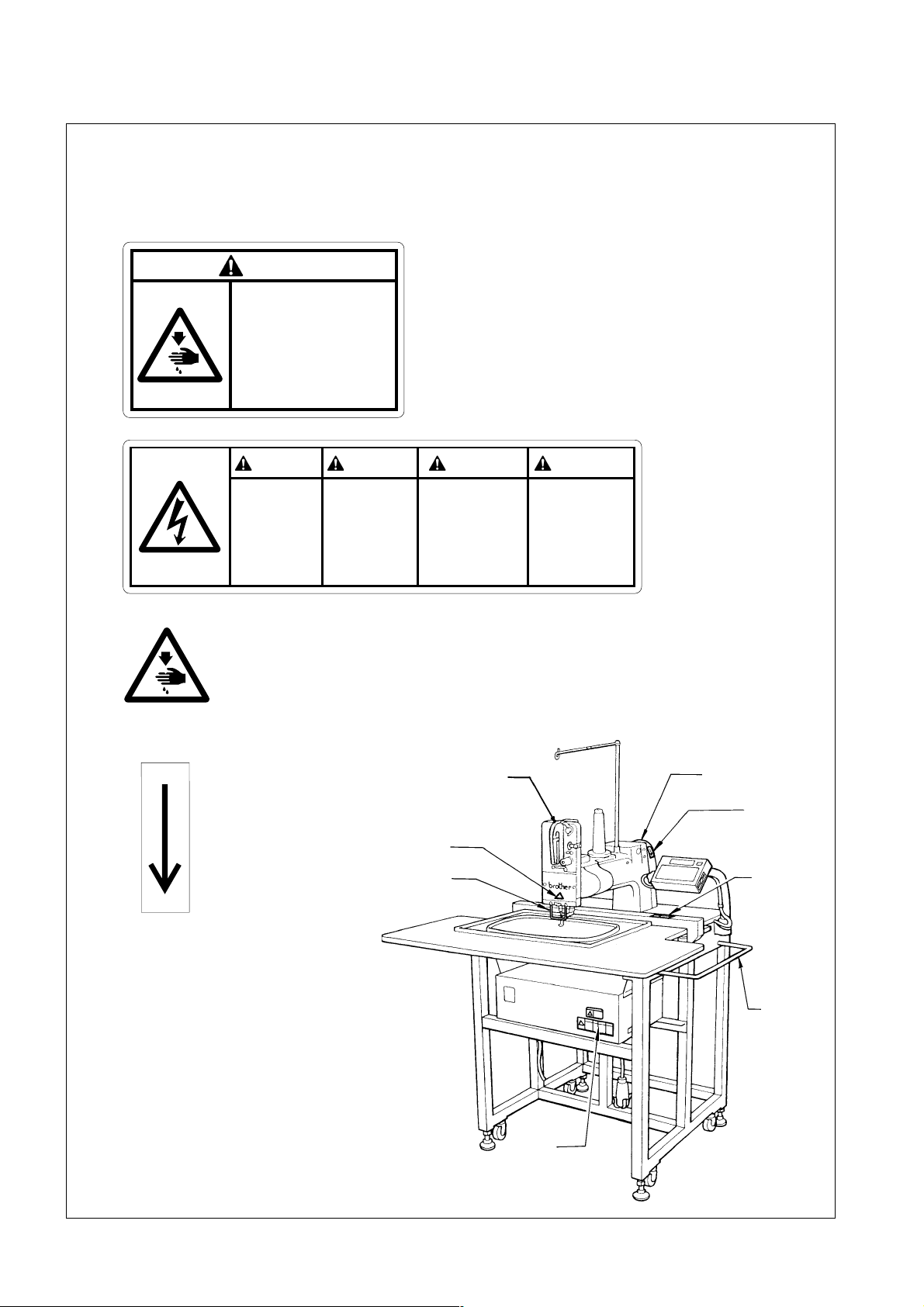
3 Warning labels
* The following warning labels appear on the sewing machine.
Please follow the instructions on the labels at all times when using the machine. If the labels have been
removed or are difficult to read, please contact your nearest Brother dealer.
1
Safety devices: Finger guard, Belt cover, etc.
CAUTION
Moving parts
may cause injury.
Operate with safety devices.
turn off main switch before
changing needle, cleaning
etc.
2
3
DANGER GEFAHR
Hazardous voltage
will cause injury,
Turn off main
switch and unplug
power cord before
opening this cover.
Never touch or push the
needle bar during operation
as it may result in injuries or
damage to the sewing machine.
Hochspannung
verletzungsgefahr!
Vor Öffnen des
Gehäuses
Hauptschalter
ausschalten und
Netzstecker ziehen!
DANGER
Un voltage non adapté
provoque des blessures.
Pour ouvrir cette plaque,
couper le contact
general de la machine
et debrancher le cable
d’alimentation.
PELIGRO
Un voltaje inadecuado
puede provocar las
heridas.
Antes de abrir esta
tapa, desconecte la
máquina y
desenchufela de la red.
4
Direction of operation
Thread take-up
Belt cover
cover
4
3
Finger guard
1
Guard bar
2
4
BES-116AC
Page 7
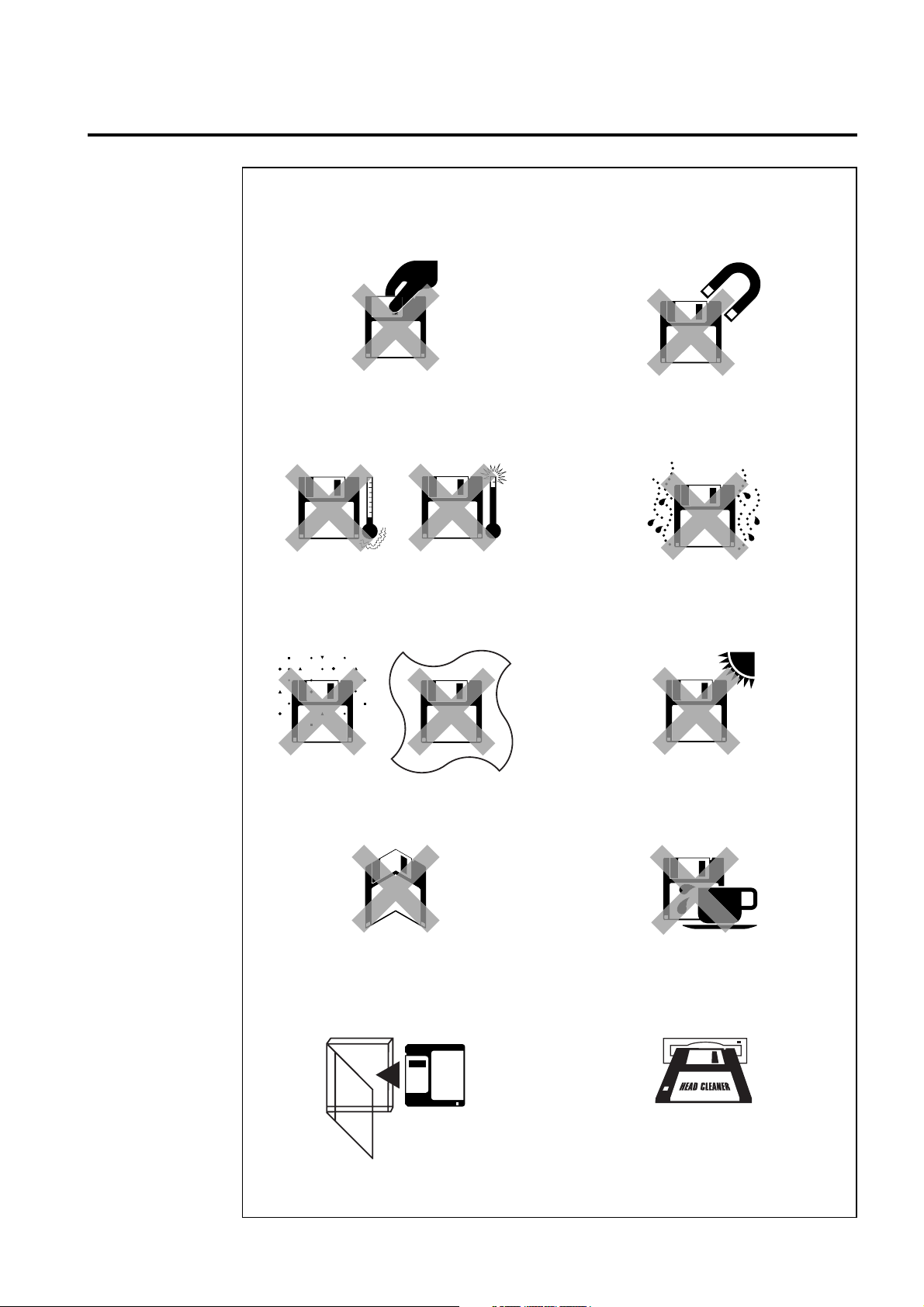
Before Starting Operation
Do not force open the shutter for
direct contact with the magnetic
area.
Do not store floppy disks in an
extremely high or low ambient
temperature.
Do not use or store floppy disks in a
dusty place.
Do not place it on cloth.
Do not bring disks near magnetic
matters such as magnetic
screwdriver or the back side of the
programmer.
Do not use floppy disks under high
humidity.
Do not store floppy disks under
direct sunlight.
Do not bend the disk. Do not put
things on the disk.
Store it in the case immediately after
using it to protect it from dust and
damage.
Avoid contact with solvent or drink.
Use a commercially available
cleaning disk to clean the head of
the floppy disk drive periodically.
Do not remove the disk out of the drive during the access lamp is lit.
BES-116AC
5
Page 8
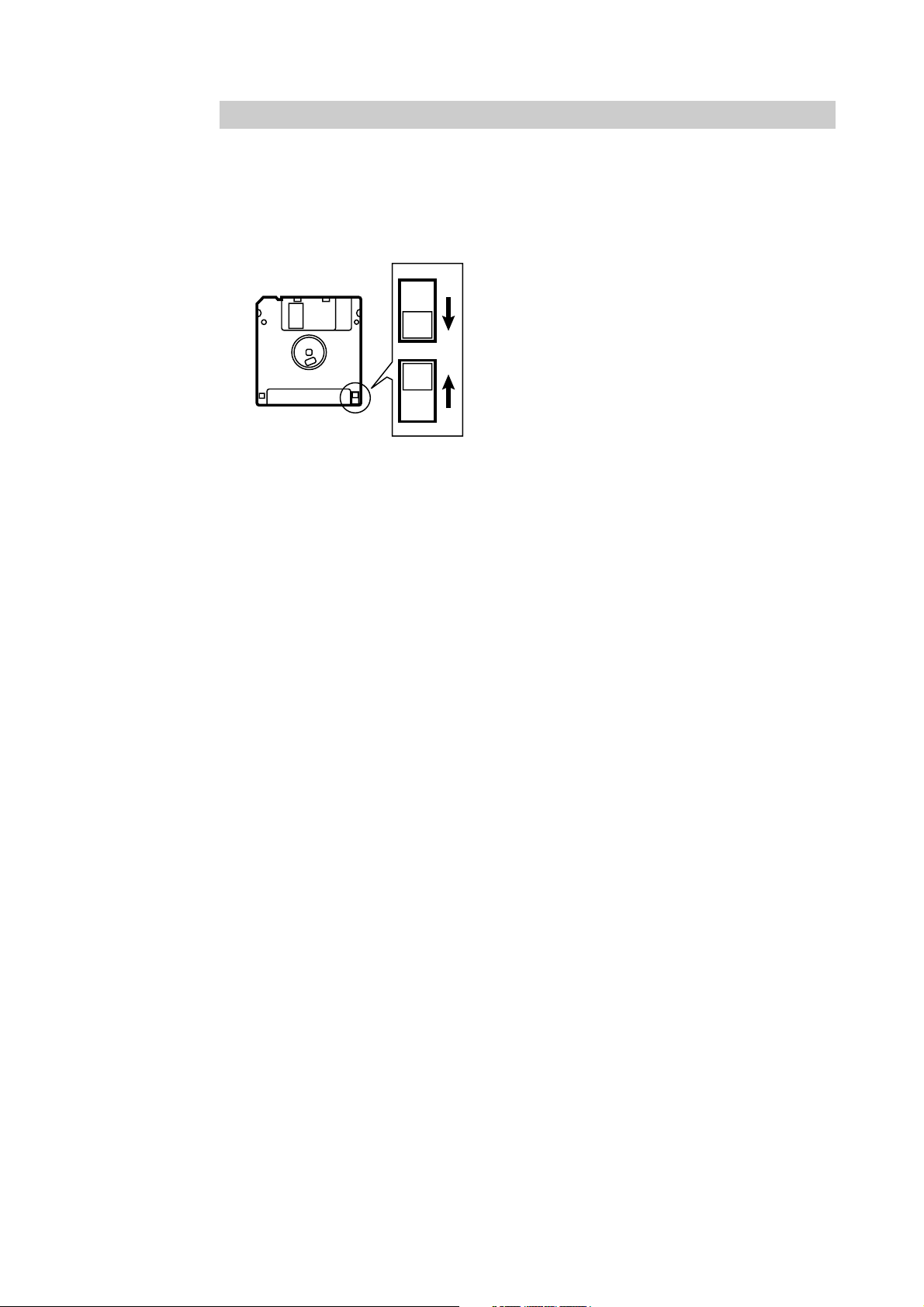
Protecting data in floppy disks
Write-protection is available for a floppy disk to prevent undesired data deletion.
A write-protected disk is read-only. It is recommended to provide write-protection
for disks which contain important data.
To do so, slide the write-protect notch to open the slot as shown below.
Slide the notch in this direction to
prevent data loss or overwriting.
Slide the notch in this direction to write
data.
6
BES-116AC
Page 9

Procedure of Reading This Manual
This manual consists of the following chapters:
Chapter 1 Preparation of Embroidery Machine
This Chapter describes the specifications, installation and preparatory procedures of
starting up the machine.
Chapter 2 Embroidering Procedures
Provides explanations on the operation panel and briefly reviews the flow of
embroidering processes.
Chapter 3 Selection of Data and Embroidering
This Chapter describes procedures of reading sewing data and sewing.
Chapter 4 Editing of Embroidering Data
Explains how to edit the embroidery data.
Chapter 5 Setting
This Chapter describes procedures of setting the machine and working environment.
Chapter 6 Operation of Machine
Provides information on machine operation during embroidering.
Chapter 7 Maintenance
Describes appropriate maintenance of the machine.
Chapter 8 Adjustment
Explains how to adjust the needles.
Chapter 9 List of Error Messages
Provides information on error codes and action to be taken.
Chapter 10 Troubleshooting
Provides troubleshooting for the machine.
Connection and Installation of Optional Equipment
Describes connections between the machine/computer and optional equipment
available.
BES-116AC
7
Page 10
Screen Composition
Initial Screen
Starting Sewing Selection of Embroidery data
STOP
Operation ( page 56)
Canceling of Sewing
Thread trimming Setting of Needle Bars
Hoop Retract
Area Check Editing of Embroidery data
( page 45)
page 76)
(
page 61)
(
8
BES-116AC
Page 11
Setting of thread breakage sensor ( page 78)
Setting of Machine ( page 81)
BES-116AC
9
Page 12

Contents
SAFETY INSTRUCTIONS ............................................................................ 1
Before Starting Operation .......................................................................... 5
Procedure of Reading This Manual ........................................................... 7
Screen Composition ................................................................................... 8
Chapter 1 Preparation of Embroidery Machine
1. Specifications ........................................................................................ 16
2. Names of Machine Components .......................................................... 17
3. Installation ............................................................................................. 18
3-1 Transportation of Machine ..........................................................................18
3-2 Installation of Machine ................................................................................18
3-3 Installation of Operation Panel....................................................................19
3-4 Attaching the tead guide bar and the thread guide.....................................19
3-5 Mounting of Guard Bar................................................................................19
3-6 Attaching the 9-spool cotton stand (optional)..............................................20
3-7 Bobbin winder (optional) .............................................................................21
4. Preparation for Embroidering .............................................................. 23
4-1 Upper Threading .........................................................................................23
4-2 Replacement of Bobbin...............................................................................24
4-3 Replacing and Selecting Needle.................................................................25
4-4 Connection to Power Source ......................................................................26
4-5 Preparation of Machine for Operation.........................................................26
4-6 Attachment of Embroidery Hoop and Frame ..............................................29
4-7 Adjustment of Thread Tension....................................................................33
Chapter 2 Embroidering Procedures
Functions of Operation Panel .................................................................. 36
Operation Panel ................................................................................................36
Shut-off switch unit............................................................................................39
Stop switch unit .................................................................................................39
Flowchart of Preparation for Embroidering............................................ 40
Turn on the Machine Power ..............................................................................41
Retrieve the Embroidery Data...........................................................................42
Start Embroidering ............................................................................................42
Chapter 3 Selection of Data and Embroidering
What Can the Machine Do? ...................................................................... 44
Selection of Data ....................................................................................... 45
Registration of Embroidery Data from Floppy Disk ...........................................45
10
BES-116AC
Page 13

Reading from Memory.......................................................................................48
Registration of Embroidery Data from BE-100..................................................49
Deletion of Embroidery Data from Machine Memory ........................................50
Modification of Embroidery Data Name .................................................. 52
Sewing Operation ...................................................................................... 56
Before Starting Sewing .....................................................................................56
Starting Sewing Operation ................................................................................56
Feedhold and Cancellation of Sewing...............................................................57
Step Forward and Step-Back ................................................................... 58
Step Forward/Step-Back Mode .........................................................................58
Setting Amount or Timing of Step Forward/Step-Back .....................................58
For Step Forward (Back)...................................................................................59
Resuming Sewing .............................................................................................59
Writing the embroidering data ................................................................. 60
Chapter 4 Editing of Embroidering Data
What Can the Machine Do? ...................................................................... 62
Rotation...................................................................................................... 63
Enlargement and Reduction .................................................................... 64
Mirror .......................................................................................................... 66
Repetition ................................................................................................... 68
Other Editing ............................................................................................. 70
Chapter 5 Setting
What Can the Machine Do? ...................................................................... 74
Setting of Needle Bars .............................................................................. 76
Thread Breakage Sensor .......................................................................... 78
Setting of sensor validity/invalidity ....................................................................78
Thread Breakage Sensitivity .............................................................................78
Automatic Step-Back.........................................................................................79
Setting of Lower Thread Counter/Stitch Counter ..............................................80
Setting of Machine .................................................................................... 81
Embroidery Hoop ..............................................................................................81
Speed Range ....................................................................................................82
Speed of Each Speed Range............................................................................83
Setting of Mending ............................................................................................84
Thread Trimming Length...................................................................................84
Thread Withdrawal Feed Length.......................................................................85
Inching...............................................................................................................86
BES-116AC
11
Page 14

Sewing Area......................................................................................................87
Registration of Sewing Start Position................................................................88
Hoop Retract Point............................................................................................88
Hoop Automatic Retract ....................................................................................89
Movement to Registered Sewing Start Point ....................................................89
Setting of Environment ............................................................................. 90
Return to Start Point..........................................................................................90
Speed Range ....................................................................................................90
Checking the Embroidery Area .........................................................................91
Feed rate adjustment ........................................................................................92
Setting of RS-232C Communication Speed......................................................92
Display Language .............................................................................................93
Alarm Sound .....................................................................................................94
Motive Speed ....................................................................................................95
Small-Pitch Deletion..........................................................................................96
XY Feed Power Increase ..................................................................................97
Boring................................................................................................................98
Lock Stitch.........................................................................................................99
Speed Limit in a Short Pitch............................................................................102
Feed Timing ....................................................................................................103
Automatic Input Setting ...................................................................................104
Display of Information ............................................................................ 107
Pattern Information..........................................................................................107
Features of Machine .......................................................................................108
Information about Versions .............................................................................109
Chapter 6 Operation of Machine
1. Operating Procedures ........................................................................ 112
1-1 Power Source ...........................................................................................112
1-2 Preparation for Embroidering....................................................................112
2. Machine Stop ....................................................................................... 113
2-1 Stopping the Machine with the stop switch unit ........................................113
2-2 Emergency Stop of the Machine with the shut-off switch unit...................113
3. Hoop Feed Position ............................................................................ 114
4. Area Check .......................................................................................... 115
4-1 External Tracing........................................................................................115
4-2 Automatic Hoop Movement in Area ..........................................................115
5. Jog Switches ....................................................................................... 116
5-1 Hoop Movement to Start Position .............................................................116
5-2 Inching Mode during Embroidering (Forcible Hoop Movement) ...............117
6. Detection of Home Position ............................................................... 118
12
BES-116AC
Page 15

Chapter 7 Maintenance
1. Cleaning ............................................................................................... 120
1-1 Cleaning and Lubrication of Rotary Hook .................................................120
1-2 Cleaning of Needle Plate ..........................................................................121
2. Oiling .................................................................................................... 122
2-1 Head .........................................................................................................122
Chapter 8 Adjustment
1. Adjusting Needle Bar Height .............................................................. 126
2. Adjustment of Timing Between Needle and Rotary Hook ............... 130
3. Adjustment of Presser Foot Height ................................................... 131
4. Adjustment of Thread Trimmer .......................................................... 132
5. Adjusting the Belt Tension ................................................................. 133
Chapter 9 Error code list
Chapter 10 Troubleshooting
Mechanical Section ................................................................................. 140
Electrical Section .................................................................................... 142
Connection and Installation of Optional Equipment
Attaching Bobbin Winder (Using the 9-spool cotton stand) ............... 148
BES-116AC
13
Page 16

14
BES-116AC
Page 17

Chapter 1
Preparation of Embroidery Machine
Page 18

Chapter 1 Preparation of Embroidery Machine
1. Specifications
Embroidery machine used 1 needle embroidery machine head
Application Pattern embroidery
Sewing speed Maximum 1200 rpm
Sewing area
Feed system By pulse motor wire drive
Stitch length 0.1 ~ 12.7 mm (minimum pitch: 0.1 mm)
Storage medium
Thread trimming Automatic thread trimmer
Needle thread breakage Needle thread breakage detector
Power supply
Weight 195 kg
Dimensions 1050 (W) x 1016 (L) x 1484 (H) mm
Options
Max. 300 (V) x 450 (H) mm (flat hoop area)
85 (V) x 360 (H) mm (with cap frame)
3.5 2DD floppy disk (Tajima format)
3.5 2HD floppy disk (the equivalent to Tajima format)
3.5 2DD floppy disk (Barudan FDR/FMC format) (embroidary data in
FDR35III/V format only)
3.5 2DD floppy disk (ZSK format)
3.5 floppy disk (brother ECS format)
Single phase 120 V, 200 V, 220 V, 240 V, Standard 400 W (maximum 500 W)
Embroidery hoops in different sizes, Bobbin winder,
Cap frame device, Cotton stand 9
16
BES-116AC
Page 19
Chapter 1 Preparation of Embroidery Machine
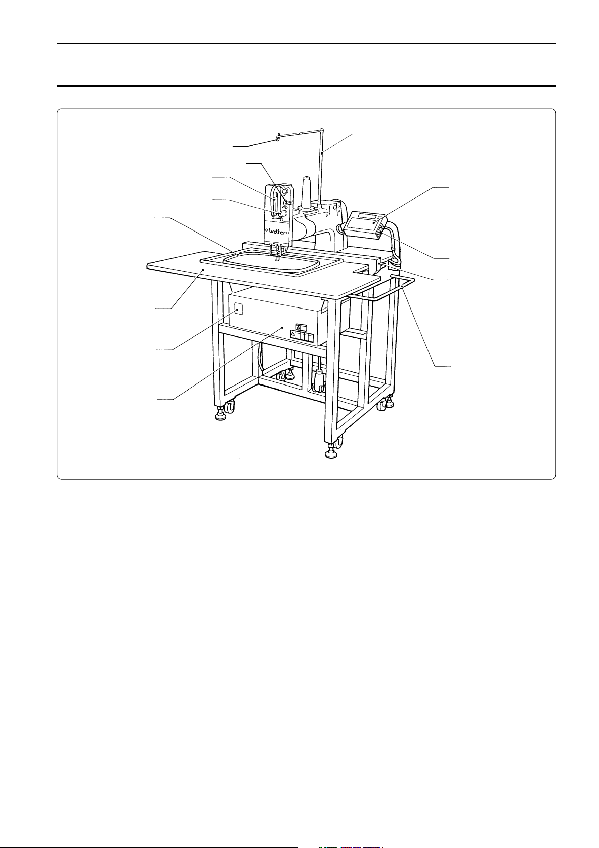
2. Names of Machine Components
Thread guide spool shaft
Thread guide
Thread breakage sensor
Thread take-up
Thread tension dial
Embroidery hoop
Table
Operation panel
Disk drive
Carriages
Power switch
Control box
Guard bar
BES-116AC
17
Page 20
Chapter 1 Preparation of Embroidery Machine
3. Installation
DANGER
Embroidery machines should be installed only
by trained engineers.
Electric wiring should be laid by your distributor or electric experts.
The sewing machine weighs more than 195 kg.
The installation should be carried out by two or
more people.
Do not connect the power source until installation is completed. Doing so may start the machine unintentionally through an accidental
activation of the START switch, resulting in
bodily injuries.
Install a machine in a place away from a highfrequency welding machine or other machines
that may generate a strong electric noise. Failure to do so may cause the embroidery machine
to malfunction.
Be sure to connect the ground. If the ground
connection is not secure, you run a high risk of
receiving a serious electric shock, and problems
with correct operation may also occur.
Secure the machine with the nuts when installing it so that it will not move by placing the leveling seat on the sound floor.
* After installation is completed, get the power supply from a dedicated outlet.
* When connecting multiple machines, exercise care not to exceed the capacity of the outlet.
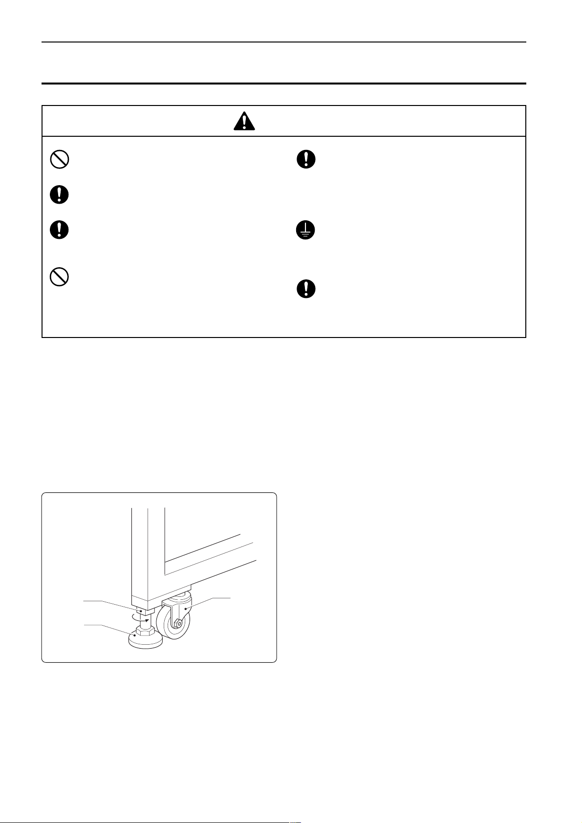
3-1 Transportation of Machine
When relocating the machine, lift it by the steel frame.
Note) Never lift the machine by the table or the guard bar.
3-2 Installation of Machine
w
q
e
1. Adjust leveling seats q by turning nuts w
in the direction of the arrow until the table
top is placed horizontally.
2. If the table is not stable, loosen nuts w and
turn leveling seats q for adjustment.
When relocating the machine, raise leveling seats q.
The machine can then be moved with casters e.
18
BES-116AC
Page 21
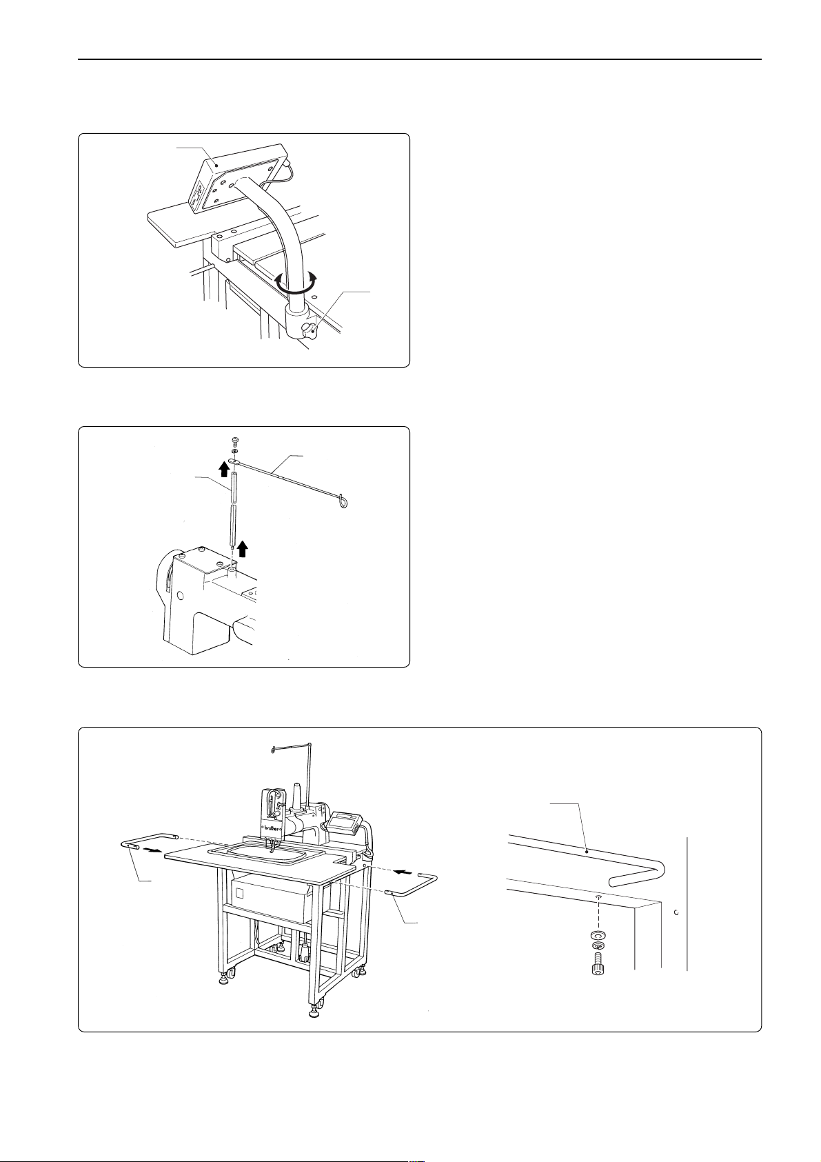
3-3 Installation of Operation Panel
Chapter 1 Preparation of Embroidery Machine
Operation panel
Loosen thumb bolt q. Adjust the operation
panel position for ease of use, and tighten
thumb bolt q.
q
3-4 Attaching the tead guide bar and the thread guide
1. Insert the thread guide bar q from the top
w
q
of the machine head by turning it.
2. Attach the thread guide q to the thread
guide bar w using the screw.
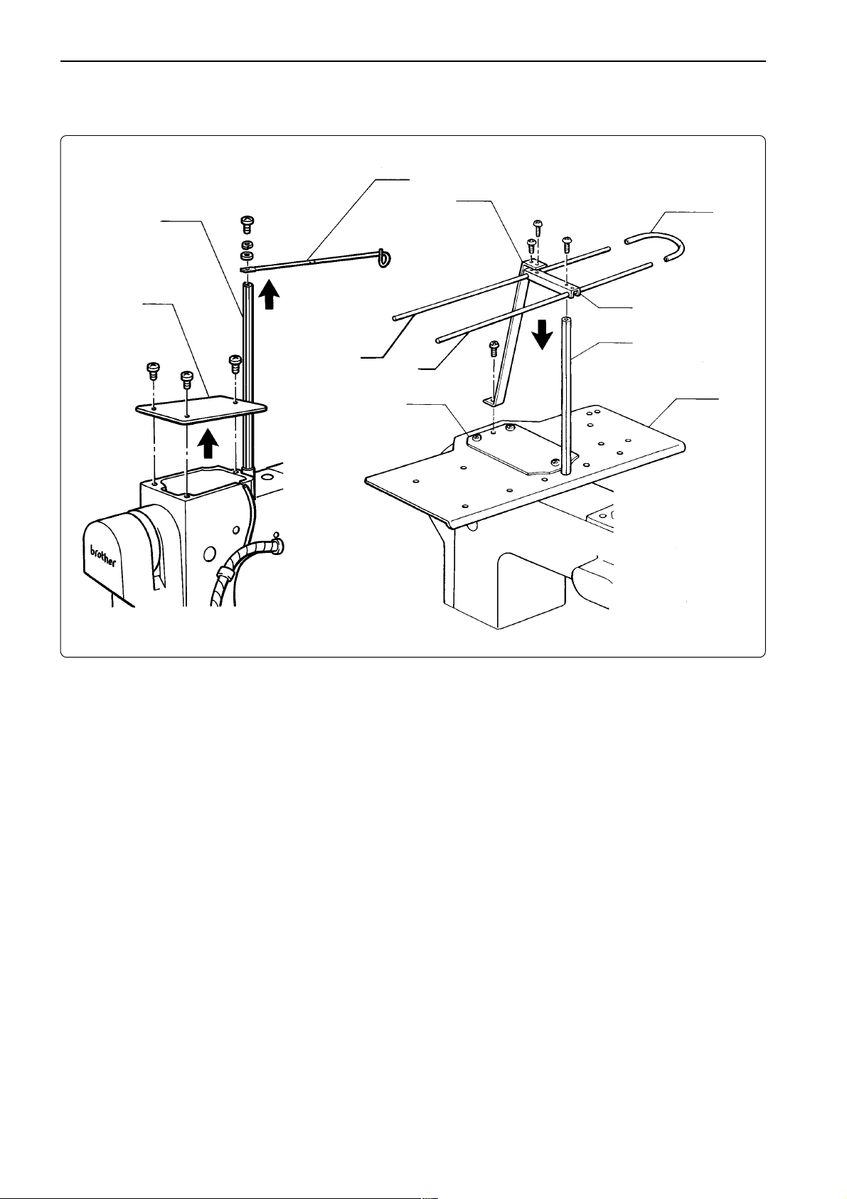
3-5 Mounting of Guard Bar
q
q
q
Attach guard bar q to the machine. Fix it with bolts, flat washer and spring washer from the
lower side of the frame.
BES-116AC
19
Page 22
Chapter 1 Preparation of Embroidery Machine
3-6 Attaching the 9-spool cotton stand (optional)
w
o
q
!0
e
u
y
t
1. Remove the screw and the thread guide w from the thread guide bar q.
i
q
r
2. Remove the screws and arm cover (R) e from the machine head.
3. Insert the thread guide bar q into the hole of cotton stand (L) r, and attach it to the machine
head using the two screws.
4. Place cotton stand (S) t on cotton stand (L) r and tighten the screw.
5. Attach thread guides (A) y and (B) u, and the thread guide joint i to the thread guide bar q,
and secure them using the screw.
6. Attach the guide plate o to the thread guide joint i and cotton stands (S) t and (L) r using
the screws.
7. Attach the vinyl tube !0 to thread guides (A) y and (B) u.
20
BES-116AC
Page 23
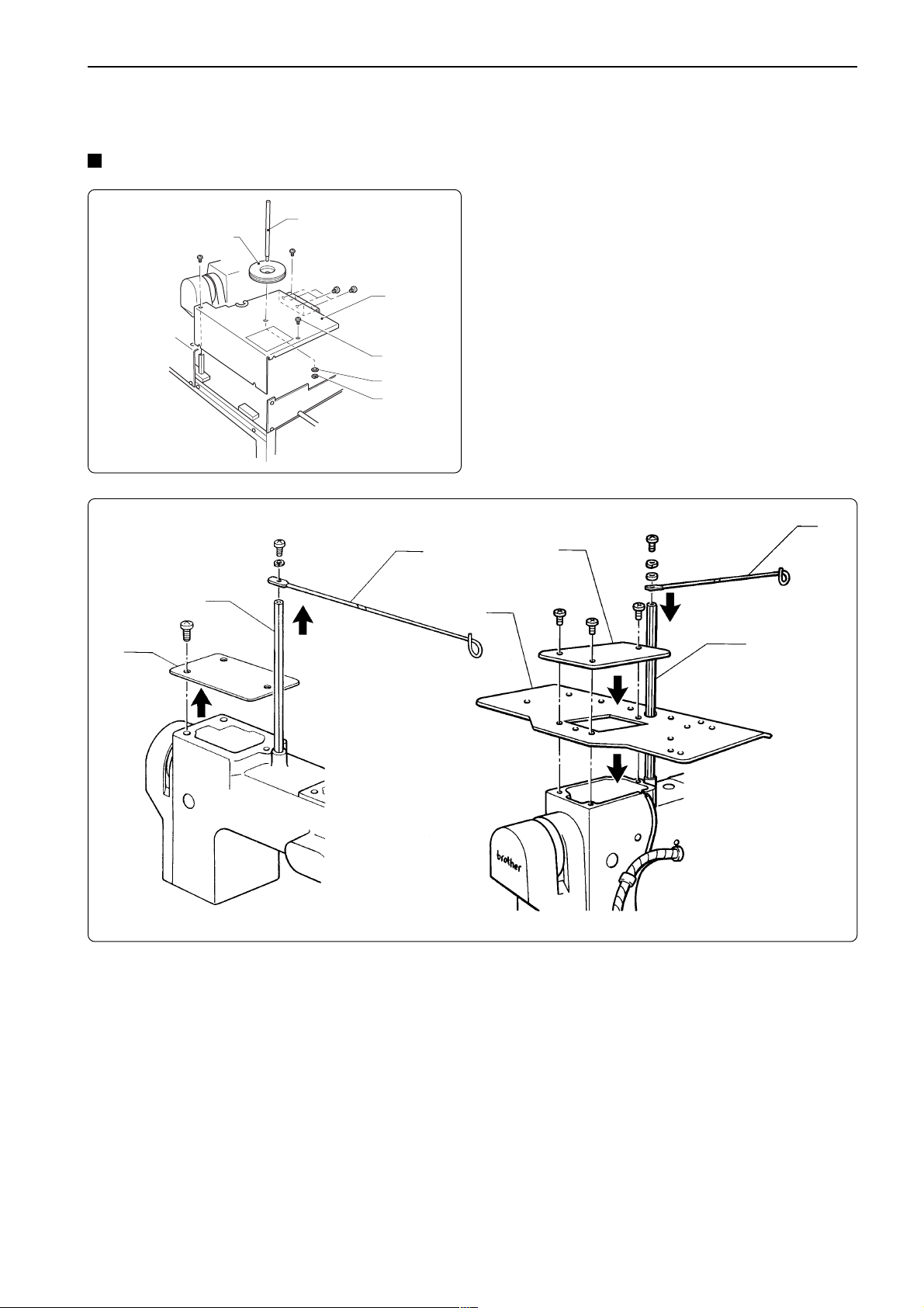
3-7 Bobbin winder (optional)
Attaching bobbin winder
t
y
q
e
r
w
Chapter 1 Preparation of Embroidery Machine
1. Loosen the eight screws q and remove
table (L) w.
2. Attach spool shaft t to table (L) w with the
washer e and the nut r.
3. Attach table (L) w to th machine body with
the eight screws q.
4. Pass spool mat y through spool shaft t.
u
o
i
u
!0
o
i
5. Remove the thread guide screw, and then remove the thread guide u from the thread guide
bar i.
6. Remove the screws, and arm cover (R) o from the machine head.
7. Install the accessory cotton stand (L) !0 with the screws, and then install it together with the
arm cover (R) o.
8. Install the thread guide bar i and the thread guide u.
BES-116AC
21
Page 24
Chapter 1 Preparation of Embroidery Machine
!0
!1
!4
!5
!3
Winding bobbin thread
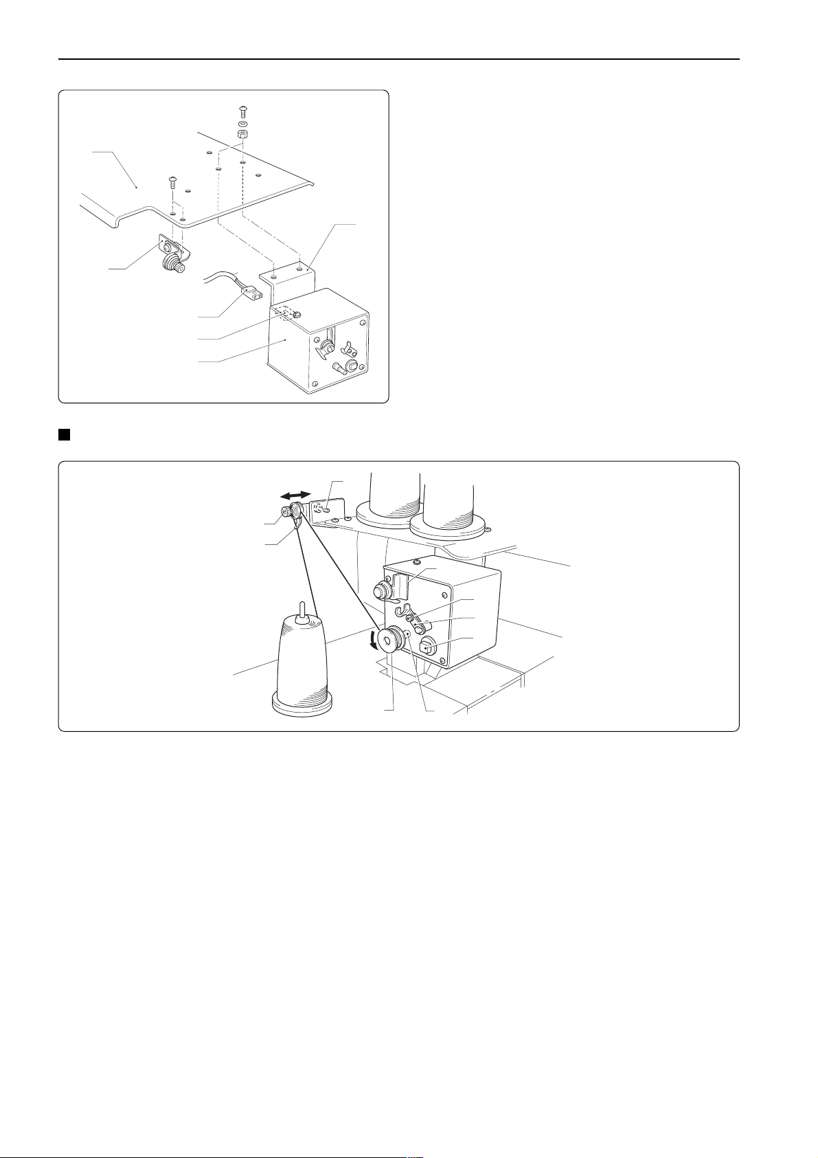
!2
9. Attach the bobbin winder guide bracket
assembly !1 to the spool stand (L) !0 with
the screws.
10. Attach the bobbin winder equipment
assembly !3 with bobbin winder plate !2 to
the machine body with the two bolts, and
then connect the bobbin winder equipment
connector !5 to the nylon connector !4.
t
i
e
u
y
r
o
q
w
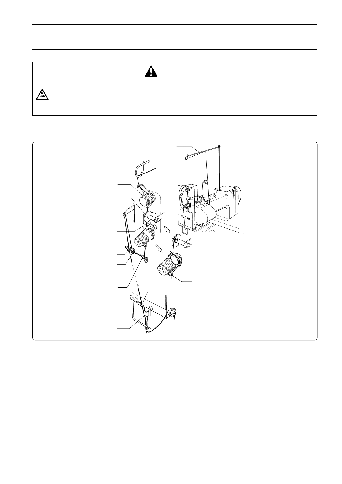
1. Turn on the machine power switch.
2. Press the bobbin q on the bobbin winder shaft w.
3. Pass the thread through the thread guide e.
4. Wind the thread on the bobbin q several times in the direction of the arrow.
5. Press the bobbin presser r.
NOTE) If the thread is not wound evenly on the bobbin, loosen the screw t and move the thread guide e right and
left. When winding more thread on the bobbin, loosen the screw y, then move the bobbin presser r.
6 When the winding is finished, remove the bobbin from the bobbin winder shaft and trim the
thread with the thread trimmer u.
NOTE) • If the thread comes out from the thread guide e, loosen the knob i. If the thread is wound too loose,
tighten the knob i.
• The thread winder motor does not operate if the circuit protector activated. In that case, leave the
protector until it's cooled off. Then, press the protector switch o. (If the protector is not cooled off, the
switch does not work.)
22
BES-116AC
Page 25
Chapter 1 Preparation of Embroidery Machine
4. Preparation for Embroidering
CAUTION
Turn off the power switch before starting preparation.
Failure to do so may start the machine unintentionally through an accidental activation of the START switch,
resulting in bodily injuries.
4-1 Upper Threading
qThread guide
wPre-tension
eThread breakage pulley
rLower thread guide (upper)
iCenter thread guide (left)
uCenter thread guide (center)
yCenter thread guide (right)
!0Needle bar thread guide
oLower thread
guide (lower)
tThread take-up spring
!1Disc
1. Pass the needle thread from the cotton stand through the two loops in the thread guide q
from right to left.
2. Pass the thread through the thread guide of the pre-tension w. Then open the thread guide
plate with your finger so that the thread passes through correctly, and then pass the thread
through the hole at the bottom of the thread guide.
3. Wind the thread twice around the pulley of the thread breakage sensor e, starting from the
front of the pulley, and then pass the thread through the lower thread guide (upper) r.
4. Wind the thread once to the right between the rotary tension discs and then hook it onto the
thread take-up spring t.
5. Hook the thread onto the center thread guides (right y and center u), pass it through the
thread take-up lever, and then pass it once more through the center thread guide (left) i.
6. Pass the thread through the lower thread guide (lower) o, hook it onto the needle bar thread
guide !0, then pass it through the needle eye and hook it onto the disc !1.
BES-116AC
23
Page 26
Chapter 1 Preparation of Embroidery Machine
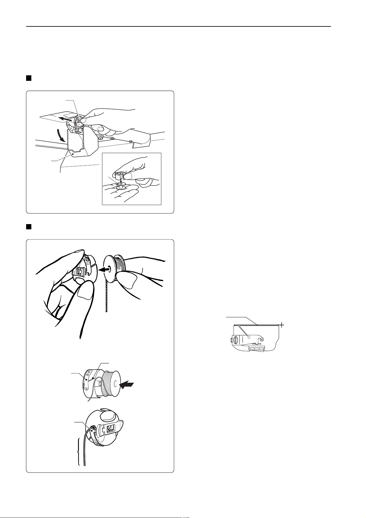
4-2 Replacement of Bobbin
Note) Remove dust, lint and oil from the bobbin case before replacement.
Removing bobbin case
w
q
Replacing bobbin
1. Open the rotary hook cover q.
2. Hold the knob w and take out the bobbin
case.
3. Close the knob and take out the bobbin e.
e
1. Put a new bobbin in the bobbin case.
Check the winding direction. (refer the figure)
If the bobbin is inserted in the reverse direction, the lower
thread may slip too much, resultingin a problem in embroidering.
Check that the bobbin is pushed out of the bobbin case
by about 0.5 mm. If not, the slip prevention spring of the
bobbin case does not work. Adjust the height of the
spring or replace it with a new one.
Bobbin
0.5mm
r
t
2. Slide the thread under the tension spring
t through the notch r.
3. Pull out the thread from the hole of the
t
tension spring t.
4. Pull out the thread by about 50 mm.
Pull out by about
50 mm
24
BES-116AC
Page 27
Attaching bobbin case
Chapter 1 Preparation of Embroidery Machine
w
q
4-3 Replacing and Selecting Needle
q
w
1. Hold the knob w and attach the bobbin
case securely.
2. Close the rotary hook cover q.
Removing needle
Loosen the set screw q and remove the needle
w.
Attaching needle
With the flat side facing the front, insert the
needle all the way until it meets the end of the
needle bar. Tighten the set screw q firmly.
Note) • Set the needle so that the notched part will
come on the rotary hook side.
• The needle eye should not be angled to the
left (when viewed from the front).
* Relationship between materials and needles
Material
Denim
Leather
Handkerchief
Shirt
Towel
Needle
DB x K5
Needle thickness
#14,
#16, #18
#9, #10
#11,
#12, #13
Selecting needle
• When using special threads such as gold,
silver, and rame yarn, use a heavy-duty
needle (#11 ~ #16). For better finish, paste
the waxed paper on the back of the
material.
• In general, use DBxK5 #11 ~ #18 according
to the material thickness. For knitted
materials, use DBxK23 #11 because its
rounded point prevents the knit thread from
breaking.
BES-116AC
25
Page 28
Chapter 1 Preparation of Embroidery Machine
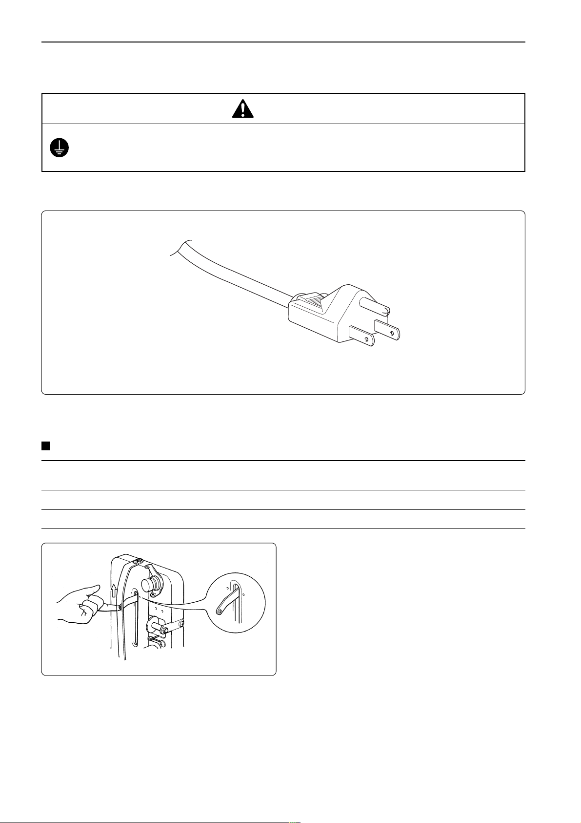
4-4 Connection to Power Source
DANGER
Be sure to connect an earth cable.
Failure to do so may result in electric shock.
Use a cord plug that matches the receptacle type.
4-5 Preparation of Machine for Operation
Check the following before turning on the power
Thread (1) Is upper thread setting complete? (2) Is the thread passed smoothly?
(3) Is thread passed through needle? (4) Is the lower thread setting complete?
Embroidery hoop (1) Is there any looseness in the material? (2) Is the hoop clamped securely?
Needle stop position (1) Is thread take-up positioned correctly? (2) Is needle bar positioned at the top?
Check that the thread take-up lever is
aligned with the index mark.
Turning on the power switch brings up the
message "Moving frame" and sounds a
beep as a warning. Then, the X and Y
carriages move the embroidery hoop to the
home position or the position where it was
located at the end of the previous
operation. Check that there is no obstacle
above the hoop which will interfere with
needle or presser foot.
26
BES-116AC
Page 29
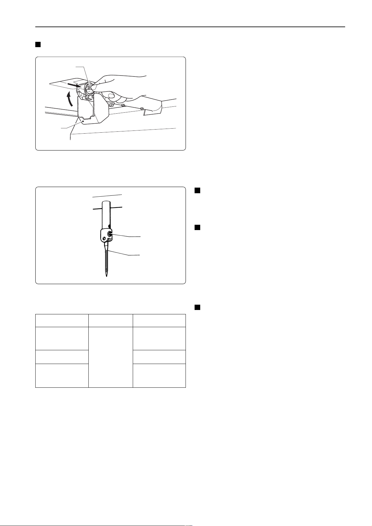
Chapter 1 Preparation of Embroidery Machine
When the machine is turned on:
If the machine is not ready to operate because the needle bars in the drive position are out of
the normal position, the message "Needle stop position error" appears. Follow the steps
below if this occurs.
1. Set "100° ( )" on the pulley to "STOP
POSITION."
Normal needle stop position
q
w
q
w
2. Press
Note) Check if the needle bars are lowered. If so,
.
STOP
return them to the normal stop position. (Refer to "Normal needle stop position" on page
27.)
3. The message "Moving frame" appears and
a buzzer sounds four times. The X and Y
carriages move automatically so as to bring
the hoop center to the home position or to
the position where it was located at the end
of the previous operation.
4. The main menu appears.
Viewing the inside through the clearance,
needle bar is in the jump position at the top
(as shown in the figure) and needle bar
vertical piece q lowers to keep it from
contact with needle bar clamp w. (The
thread take-up lever is aligned with the
index mark.)
Note) When the power switch has been turned on
or when restarting embroidering while the
machine is stopped or suspended, be sure to
return the needles to the normal stop position.
• Align thread take-up to the normal position.
• If the needle bar in the embroidering posi-
tion is lowered with needle bar vertical
piece q, separate them in the following
manner. For safety, insert a tool such as a
screwdriver into the clearance at the front
left side of the needle bar case and turn the
needle bar vertical piece w by pushing its
end. When the needle bar and the needle
bar vertical piece are separated, the needle
bar is raised to the top by the spring.
BES-116AC
27
Page 30
Chapter 1 Preparation of Embroidery Machine
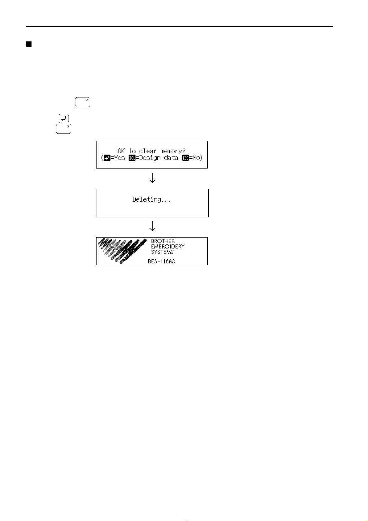
Clearing internal memory
Internal memory can be reset to the status before shipment.
Follow the steps below to clear memory:
1. Turn off the machine power switch.
2. Hold down
3. Press
When
DEL
DEL
, and turn on the power switch.
.
is pressed, only the embroidery data is cleared. Therefore, other setting data is saved.
4. Memory has been cleared.
28
BES-116AC
Page 31

4-6 Attachment of Embroidery Hoop and Frame
Attaching a square frame and a flat hoop frame (standard)
e
w
Chapter 1 Preparation of Embroidery Machine
y
t
Figure A
r
q
Figure B
r
1. Attach flat hoop frame (assembly) q to X carriage w, and tighten two screws e.
Fit the projections of the X carriage into the inner holes.
2. Loosen two screws r. Attach square frame t.
3. As shown in Figure A, fit the left metal part of the square frame to the screw. As shown in
Figure B, fit the right metal part to the screw. Tighten two screws r securely.
4. If the material over the square frame is not set properly, stitches may be skipped, threads
may be broken, or the material may shrink during embroidering. Make an adjustment using
screw y.
BES-116AC
29
Page 32

Chapter 1 Preparation of Embroidery Machine
Attaching a tubular round frame (optional)
Note) When using a tubular round frame with the frame for it, remove table from the machine.
Figure A
w
e
Figure B
y
t
q
u
r
i
o
Figure C
t
y
1. Attach two frame sets w for tubular round frame to X carriage q with two screws e.
Fit the projections of the X carriage into the inner holes.
2. As Figures B and C show, while pushing up plate springs t, insert the right and left metal
parts of tubular round frame r and fit projections y into the hole of the tubular round frame.
3. If the material over the tubular round frame is not set properly, stitches may be skipped,
threads may be broken, or the material may shrink during embroidering. Make an adjustment
using screw u.
4. Remove screw o in Figure A. Position frame arms i R and L for the tubular round frame
according to the mounting pitch of the tubular round frame, and attach the arms.
Note) Attach the frame arms R and L symmetrically.
30
BES-116AC
Page 33

Attaching a sash frame set (optional)
e
r
t
w
q
Chapter 1 Preparation of Embroidery Machine
1. Turn off the machine power switch.
2. Pull X carriage q fully toward you. Loosen
two screws e. Remove flat hoop frame
(assembly) w with spring washers r and
plane washers t from X carriage q.
Note) Save the two screws, spring washers, and
plane washers removed in the above step.
They will be used later.
Projection
y
q
u
e
r
t
Projection
y
i
3. Fit spacer u to the projection of frame base
plate assembly y mounted on X carriage
q.
4. After attaching spacer u, attach sash
frame i in the same manner and fix them
using screws e, spring washers r, and
plane washers t removed in step w.
Note) When attaching the sash frame, check that the
side with felt affixed to the back faces the
front.
u
BES-116AC
31
Page 34

Chapter 1 Preparation of Embroidery Machine
!0
o
i
!0
o
5. Put material over sash frame i. Attach two
clips 290 o to both vertical sides securely.
Also attach two clips 220 !0 to both
horizontal sides securely.
With a sash frame, the allowable embroidery area is 300
mm (vertical) x 450 mm (horizontal).
300mm
450mm
32
BES-116AC
Page 35

4-7 Adjustment of Thread Tension
0.7~1.3N
Chapter 1 Preparation of Embroidery Machine
Adjustment of upper thread
If the needle thread tension is too high, turn the
dial counterclockwise.
If the needle thread tension is too low, turn the
dial clockwise.
Adjust upper thread tension to 0.7~1.3N when
the thread is pulled at the needle bar thread
guide.
Upper stitch
width
Adjustment of tension spring
Lower
stitch
width
Upper
thread
Lower
thread
* Correct adjustment
Turn the upper thread tension dial so that the
needle thread can be pulled to the back of the
material and that the lower stitch width will be
about 1/3 of the upper stitch width.
q
w
0.07~0.12N
1. The tension spring should be adjusted to 6~8 mm in height and 0.07~0.12 N in force.
BES-116AC
6~8mm
w
33
Page 36

Chapter 1 Preparation of Embroidery Machine
2. For adjusting the height, loosen the screw q and turn the upper thread tension assembly.
3. For adjusting the tension spring force, insert a driver tip in the groove of the thread tension
bar w and turn it.
Lower thread tension
The standard tension of the lower thread is 0.2~
0.3N.
This tension may vary depending on the used
thread. In general, press the bobbin case to a
smooth vertical surface and hang the
designated number of coins. Turn the thread
tension screw so that the lower thread will come
out smoothly.
To tighten
To loosen
34
BES-116AC
Page 37

Chapter 2
Embroidering Procedures
After installation of machine start embroidering. This chapter explains about the operation panel on the machine as well as precautions for the actual embroidering process.
Page 38

Chapter 2 Embroidering Procedures
ESC
END
INS
DEL
Functions of Operation Panel
Operation Panel
ESC
START
STOP
INS
DEL
END
P Q R S
SPACE
2
1
A B C D E F
.
4
5
J K LG H I M N O
7 8 9
T U V
W X Y Z
0
FLAT CAP
HOOP
3
6
Starts embroidering.
Restarts after moving the carriage to embroidering start position by using the jog switch.
Restarts embroidering after a suspension.
STOP
Cancels errors during embroidering.
Suspends embroidering.
Selects sewing data. ( "Chapter 3 Selection of Data and Embroidering" page 43)
Specifies a sequence of colors (sequence of needle changes) in sewing data.
( "Setting of Needle Bars" page 76)
36
BES-116AC
Page 39

Chapter 2 Embroidering Procedures
Edits sewing data. ( "Chapter 4 Editing of Embroidering Data" page 61)
Sets the upper thread breakage sensor. ( "Thread Breakage Sensor" page 78)
Machine motions can be set. ( "Chapter 5 Setting" page 73)
Trims thread during suspension.
Moves the hoop to a preset hoop retract position. When this switch is pressed again, the
hoop returns to the previous position.
Checks the embroidering area.
Moves the hoop automatically into the embroidering area when the embroidery position
is out of the area.
2
ESC
INS
DEL
1
.
4
7 8 9
P Q R S
3
A B C D E F
5
6
J K LG H I M N O
T U V
W X Y Z
END
0
SPACE
Used for selecting data and setting functions.
BES116AC
37
Page 40

Chapter 2 Embroidering Procedures
FLAT CAP
HOOP
Selects the flat or cap hoop. This selection should be done before turning the power ON
to the machine. The setting will not be changed if the selection is done after turning the
power OFF.
Moves the hoop.
Step-back or forward is available during suspension. (Use switches only.)
Changes the speed range during embroidering (Use switches only).
Carries out inching of the hoop when the switch is pressed in the inching mode.
Move the cursor for selecting sewing data and an icon.
Change to the screen for selecting sewing data.
Operation panel
Contrast volume
Adjusts the screen contrast.
SBUS interface connector
Not used (Do not connects anything.)
RS-232C interface connector
Connect personal computer with BE-100 installed, etc.
38
BES-116AC
Page 41

Chapter 2 Embroidering Procedures
Shut-off switch unit
The operation panel is equipped with the shut-off switch unit, depending on the
model.
Power switch
Emergency stop switch
Power switch
Press this switch to turn on the machine. The switch is valid while the breaker
switch is on and the emergency stop switch is reset.
Emergency stop switch
Press this switch to shut off the machine. Pressing the switch locks it while it is held
down. To unlock the switch, turn it clockwise.
Stop switch unit
The operation panel is equipped with the stop switch unit, depending on the model.
Stop switch
Stop switch
Press this switch to stop embroidering. When the switch is pressed, "Release stop
SW to operate!" appears. Pressing the switch locks it while it is held down. To
unlock the switch, turn it clockwise.
BES116AC
39
Page 42

Chapter 2 Embroidering Procedures
Flowchart of Preparation for Embroidering
Turn on the machine power. ( page 41).
Retrieve the embroidery data (
"Chapter 3 Selection of Data and Embroidering" ( page 43)
Press
on the operation panel.
Press on the operation panel.
page 42).
Edit the retrieved embroidery data.
"Chapter 4 Editing of Embroidering Data" ( page 61)
40
BES-116AC
Page 43

Chapter 2 Embroidering Procedures
Turn on the Machine Power
1. Turn on the power to the machine.
2. A message is displayed on the LCD as soon as the power is turned ON.
3. The alarm sounds three times. The needle bar and the presser foot move
up. The hoop moves back to the zero point and the sewing screen is
displayed.
The speed range and actual speed is displayed.
A sequence of changing colors is displayed.
A sequence of colors is displayed.
A total number of stitches is displayed.
A data name is displayed.
A kind of hoop is displayed.
Operational icons are basically displayed; however, some icons,
such as
Feed timing according to the cloth thickness is displayed.
, may not be on the screen.
STOP
BES116AC
41
Page 44

Chapter 2 Embroidering Procedures
Retrieve the Embroidery Data
The description in this section is based on the method of reading data which is
registered in the memory unit of the machine.
Refer to "Selection of Data" (
Page 45) for details.
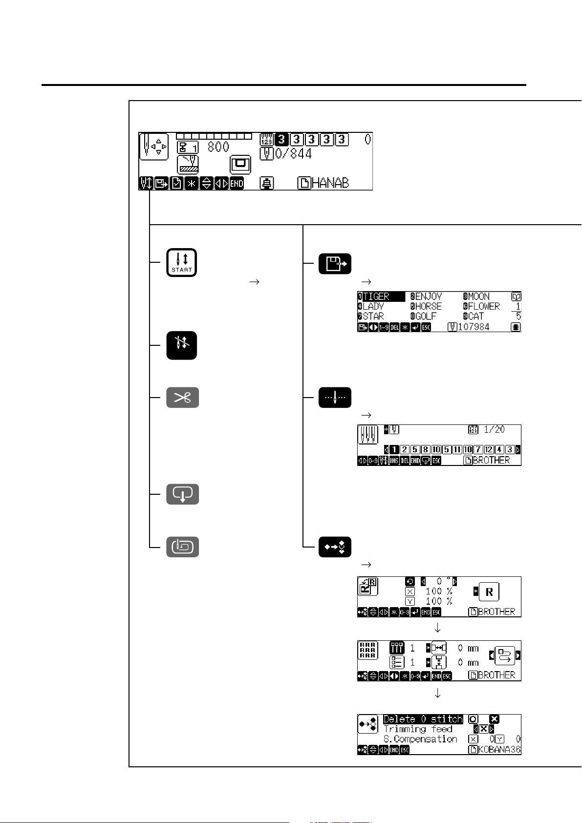
1. Press
Data saved in the machine is displayed.
switch.
2. Select a screen by pressing keys, and select required data by
pressing ten keys or
When using ten keys for data selection, input a numerical figure (1 ~ 9) which indicates each
data name. Required embroidery data is selected and read.
.
3. Press key.
Required embroidery data is selected and read.
Selected embroidery data is read.
Start Embroidering
1. Press to check the embroidering area.
2. Press
Sewing is started and the next screen is displayed.
to start embroidering.
42
BES-116AC
Page 45

Chapter 3
Selection of Data and Embroidering
This Chapter describes how to select embroidery data in order to start embroidering.
Page 46

Chapter 3 Selection of Data and Embroidering
What Can the Machine Do?
Selection of Embroidery Data
Registration of data from the floppy disk ( Page 45)
Reading of data from the memory ( Page 48)
Registration of data created by BE-100 ( Page 49)
(These icons are displayed in the lower right of the screen.)
Modification of data name ( Page 52)
Deletion of embroidery data ( Page 50)
Embroidering Operation
Embroidering start ( Page 56)
Embroidering feedhold ( Page 57)
Embroidering cancel ( Page 57)
Step forward/step back ( Page 58)
Step forward (back) stitch by stitch
Step forward (back) by every 10 stitches
Step forward (back) by every 100 stitches
Step forward (back) until a next color change
Step forward (back) to the embroidering start point
of a next pattern
Step forward (back) by a specified number of
stitches ( Page 58)
44
BES-116AC
Page 47

Selection of Data
Select data in order to start sewing.
Data to use for actual embroidering is selected from data registered in the machine
memory. A maximum of 45 kinds or 480,000 stitches of embroidery data can be
registered in the machine memory; however, depending on the combination of
embroidery data, the number of total stitches available may become less.
When using data in a floppy disk or in BE-100, register it in the machine memory
once before selection.
If there is no space in the machine memory, delete unnecessary data to make a
space.
Data in a floppy disk
Chapter 3 Selection of Data and Embroidering
Machine memory
Registration
Data created by BE-100
Sewing
Reading
Registration of Embroidery Data from Floppy Disk
Register embroidery data from a floppy disk into the machine memory.
Types of data to be registered are as shown below.
• DOS-formatted data
Data format Extension Icon
ECS Data with a name of [xxxx.ECS]
Tajima Data with a name of [xxxx.DST]
Barudan Data with a name of [xxxx.DSB]
Zanks (DSK) Data with a name of [xxxx.DSZ]
Data received from BE-100 Data with a name of [xxxx.STH]
(These icons are displayed in the lower right of the screen.)
BES-116AC
45
Page 48

Chapter 3 Selection of Data and Embroidering
• Other data
Data format Icon
Barudan FDR
Barudan FMC
Zanks ZSK
Loading and Loading of Floppy Disk
1. When loading a floppy disk, set it straight with the labeled surface facing
this side.
(These icons are displayed in the lower right of the screen.)
2. When unloading a floppy disk, press the eject switch.
3. When it comes out, pull it straight.
When the access lamp is ON, never press the eject switch. Otherwise, embroidery data in the
floppy disk may be destroyed.
Eject switch
Access lamp
Registration of Sewing Data into Machine Memory
1. Load a floppy disk with sewing data.
46
BES-116AC
Page 49

2. Press .
Chapter 3 Selection of Data and Embroidering
3. Select a screen for data registration by pressing
Currently displayed screen
No. of screens to be selected
Data in machine memory
Currently selected embroidery data
When there is no data
Number of stitches in selected embroidery data
.
4. Select an area for registration, using ten keys or , then press
.
A space available is automatically selected.
Pressing automatically locates the first space in the memory.
5. Data in the floppy disk is displayed. Press to select a screen.
Currently displayed screen
No. of screens to be selected
Data in floppy disk
Icon indicating a kind of selected data
Pressing displays a pattern name.
Name of a selected embroidery pattern
(It may be the same as a file name.)
6. Select data to register by pressing ten keys or then press .
Data is newly registered in the machine memory.
Select embroidery data and press . The selected data is automatically registered in the
memory and the machine enters a standby status.
If registration is done without loading a floppy disk, the following screen is displayed after the
step 4 is finished.
Load a floppy disk for data registration.
BES-116AC
47
Page 50

Chapter 3 Selection of Data and Embroidering
Reading from Memory
Data to use for sewing can be selected from the machine memory.
A maximum 45 kinds or 480,000 stitches of embroidery data can be registered in
the memory.
1. Press
Embroidery data registered in the memory is displayed.
.
2. Select a screen by pressing .
Currently displayed screen
No. of screens to be selected
3. Select embroidery data to read by pressing ten keys or .
4. Press .
Embroidery data is selected and read.
When a free space is specified in the memory, a screen for reading data from the floppy disk is
displayed.
Refer to "Registration of Sewing Data into Machine Memory" (steps 5 and afterward on Page
47).
48
5. The initial screen is displayed.
BES-116AC
Page 51

Chapter 3 Selection of Data and Embroidering
Registration of Embroidery Data from BE-100
Connect the operation panel and the personal computer with BE-100 installed in
order to register the embroidery data into the machine memory.
1. Connect the personal computer with BE-100 installed and the operation
panel by means of the RS-232C cable.
Personal computer with BE-100 installed
Operation panel
Dedicated communication cable (Option)
2. Press the .
3. Select the data registration screen by pressing the
.
4. Select an area for data registration by pressing ten keys or , and
then press the
key.
5. Press the .
When a floppy disk is set
When no floppy disk is set
BES-116AC
49
Page 52

Chapter 3 Selection of Data and Embroidering
6. Press the .
7. The BE-100 embroidery data is displayed. Press the and select a
required screen.
8. Select embroidery data to register by pressing ten keys or , and
then press the
The data is registered in the machine memory.
key.
Deletion of Embroidery Data from Machine Memory
Embroidery data can be deleted from the machine memory.
1. Press
A list of registered data is displayed.
2. Select a screen by pressing .
.
Currently displayed screen
No. of screens to be selected
3. Select embroidery data to delete by pressing ten keys or .
50
BES-116AC
Page 53

Chapter 3 Selection of Data and Embroidering
4. When
DEL
is pressed, the confirmation message is displayed.
5. When key is pressed, selected embroidery data is deleted from the
memory.
When deleting embroidery data in the machine memory entirely:
When deleting embroidery data registered in the machine memory entirely, turn
ON the power to the machine while pressing
memory” on page 28.)
DEL
. (Refer to “Clearing internal
BES-116AC
51
Page 54

Chapter 3 Selection of Data and Embroidering
Modification of Embroidery Data Name
Name of embroidery data registered in the machine memory can be modified.
This example shows how to modify the data name "FLOWER" to "TEST003".
A maximum number of characters to use for an embroidery data name is 8.
The following kinds of characters can be used.
It is impossible to input a " . " or space.
Alphabetical characters (A ~ Z) Numerical characters (0 ~ 9)
0
Use
each is pressed as shown below.
_ (underbar), - (hyphen)
Use
SPACE
1
.
through
.
9
. An input character changes depending on the number of times
W X Y Z
5
J K L
2 times
1 time
4 times
3 times
1
.
3 times
2 times
1. Press .
Embroidery data saved in the memory is displayed.
7
P Q R S
3 times
2 times
1 time
5 times
4 times
52
2. A list of embroidery data is displayed. Select a screen by pressing .
Currently displayed screen
No. of screens to be selected
3. Select embroidery data to modify the name by pressing ten keys or
.
4. Press
.
BES-116AC
Page 55

Chapter 3 Selection of Data and Embroidering
When selected data has a pattern name, the name is displayed. Press the key once again.
5. Input a new data name by pressing ten keys.
When modifying embroidery data names entirely
6. Pressing
7. Press
"T" is input.
8. Press
"E" is input.
9. Press
"S" is input.
8
T U V
3
D E F
7
P Q R S
DEL
deletes currently reversed characters.
twice.
three times.
five times.
10. Press
8
T U V
twice.
"T" is input.
11. Press
0
SPACE
once.
"0" is input.
BES-116AC
53
Page 56

Chapter 3 Selection of Data and Embroidering
12. Press .
When inputting the same character continuously, press the to move the cursor to the right.
13. Press
"0" is input.
14. Press
"3" is input.
0
SPACE
3
D E F
once.
once.
15. After inputting a data name, press .
A data name is modified by the above procedures.
When modifying only one character:
[FLNWER] can be modified to [FLOWER] in the following procedures.
6. Press
7. Press twice and display "N" reversely.
8. Press
"N" is deleted.
.
DEL
.
54
BES-116AC
Page 57

Chapter 3 Selection of Data and Embroidering
9. Press
6
four times.
M N O
"O" is input.
10. Press .
A data name is modified by the above procedures.
BES-116AC
55
Page 58

Chapter 3 Selection of Data and Embroidering
Sewing Operation
Before Starting Sewing
Select a hoop to set on the machine.
The following operation should be done before turning the power ON to the
machine. Otherwise, it will damage the hoop.
1. Select either the flat hoop or cap hoop, using FLAT or CAP switch on the
operation panel.
When a flat or tabular hoop , or a sash frame is set on the machine, select [FLAT].
When a cap hoop is set, select [CAP].
FLAT CAP
HOOP
2. Specify an embroidery hoop set on the machine, referring to "Embroidery
Hoop" (
Page 81).
Starting Sewing Operation
For details of specifying a sewing start position, refer to "Registration of Sewing
Start Position" (
When is pressed while the message "Area over" is indicated on the screen,
a dialog box is displayed for confirming whether or not to start sewing forcibly.
Pressing
interference with the frame may occur. Exercise added care when doing so.
1. Check that sewing data has been selected, then press
Sewing is started.
Page 88).
starts sewing; however, depending on the start position, an
.
The current embroidering status is indicated.
Indicates a sequence of color changes.
Indicates a name of data currently used for sewing.
Indicates the number of data currently used for sewing.
Currently selected speed range
The range can be modified by pressing .
56
BES-116AC
No. of current stitches
Page 59

Chapter 3 Selection of Data and Embroidering
Feedhold and Cancellation of Sewing
Feedhold
1. Press
Sewing is interrupted.
STOP
.
Cancellation
1. Press
When repetition of patterns is set, a pattern which is currently being sewn is canceled. When
canceling all patterns, press
2. A message for confirmation is displayed. When canceling sewing, press
ESC
while sewing is interrupted.
once again.
ESC
.
BES-116AC
57
Page 60

Chapter 3 Selection of Data and Embroidering
Step Forward and Step-Back
Stitches can be advanced (step forward) or retracted (step-back) without sewing.
Step Forward/Step-Back Mode
1. Press when selecting either mode before starting sewing and press
when selecting a mode during sewing.
STOP
Setting Amount or Timing of Step Forward/Step-Back
A step forward/step-back amount or timing can be selected as described below.
For stepping forward (back) stitch by stitch
For stepping forward (back) by 10 stitches
For stepping forward (back) by 100 stitches
For stepping forward (back) up to the next (previous) color change
For stepping forward up to the sewing start point of a next pattern if
repetition of patterns is set.
Specify the number of stitches for stepping forward (back).
1. Select a required item as described above by pressing .
When the number of stitches is specified, the needle steps forward
(back) to an input position:
1. Press the five times.
2. Input the number of stitches to move by pressing ten keys.
3. Press the
The needle steps forward (back) as specified.
58
END
.
BES-116AC
Page 61

Chapter 3 Selection of Data and Embroidering
4. The embroidery head advances (retracts) by a specified number of
stitches.
For Step Forward (Back)
1. Press .
Stitches steps forward (back) by a specified amount.
Resuming Sewing
1. Press .
Sewing is started.
BES-116AC
59
Page 62

Chapter 3 Selection of Data and Embroidering
Writing the embroidering data
The embroidering data stored in the memory of the machine is written to the floppy disk.
The format of the data to be written is brother ESC or TAJIMA TFD.
1. Press the
The embroidering data stored in the memory is displayed.
button.
2. The list of the embroidering data is displayed. Select the screen by
pressing
.
3. Select the embroidering data to be written with numeric keys or .
4. Press the
5. Designate the thread trimming feed number with
It cannot be designated when the ECS data format is selected.
Use numeric keys,
END
button.
, or the
DEL
button to change the file name.
.
In any data format other than the ECS format In the ECS data format
6. Highlight the icon of the data format with and designate the format
of the data to be written with
7. Highlight the edit value validating or invalidating icon with
.
and
designate validating or invalidating of the edit value.
8. Set the formatted floppy disk.
END
9. Press the
The selected embroidering data is stored on the floppy disk.
button.
60
BES-116AC
Page 63

Chapter 4
Editing of Embroidering Data
Pressing on the operation panel after
reading embroidering data displays the embroidering data editing screen. Simple operation by using embroidering data is available on this screen.
Page 64

Chapter 4 Editing of Embroidering Data
What Can the Machine Do?
Editing
Enlargement/reduction is executed ahead of rotation. When an embroidery
pattern is so set to be rotated by 90˚ and then enlarged by 2 times in the X-axis
direction, the X-axis enlargement is executed first and rotation by 90˚ is executed
afterwards. Therefore, a pattern is enlarged by 2 times at the sewing point.
Rotation of embroidery pattern ( Page 63)
Enlargement/reduction of embroidery pattern in the X-axis direction
( Page 64)
Enlargement/reduction of embroidery pattern in the Y-axis direction
( Page 64)
Mirror pattern ( Page 66)
Right/left mirror pattern
Up/down mirror pattern
Zero point symmetric mirror pattern
No. of repetitions in the horizontal direction (lines) ( Page 68)
No. of repetitions in the vertical direction (rows) ( Page 68)
( ) Distance in the horizontal direction between two outer hoop
centers (
( ) Distance in the vertical direction between two outer hoop
centers (
Direction of repetitions ( Page 68)
Horizontal direction from upper left to lower right
Vertical direction from upper right to lower left
Horizontal direction from lower right to upper left
Vertical direction from lower left to upper right
Horizontal direction from upper right to lower left
Vertical direction from upper left to lower right
Horizontal direction from lower left to upper right
Page 68)
Page 68)
Vertical direction from lower right to upper left
0 stitch deletion ( Page 70)
Thread trimming feed number (
Swing width correction ( Page 71)
62
BES-116AC
Page 71)
Page 65

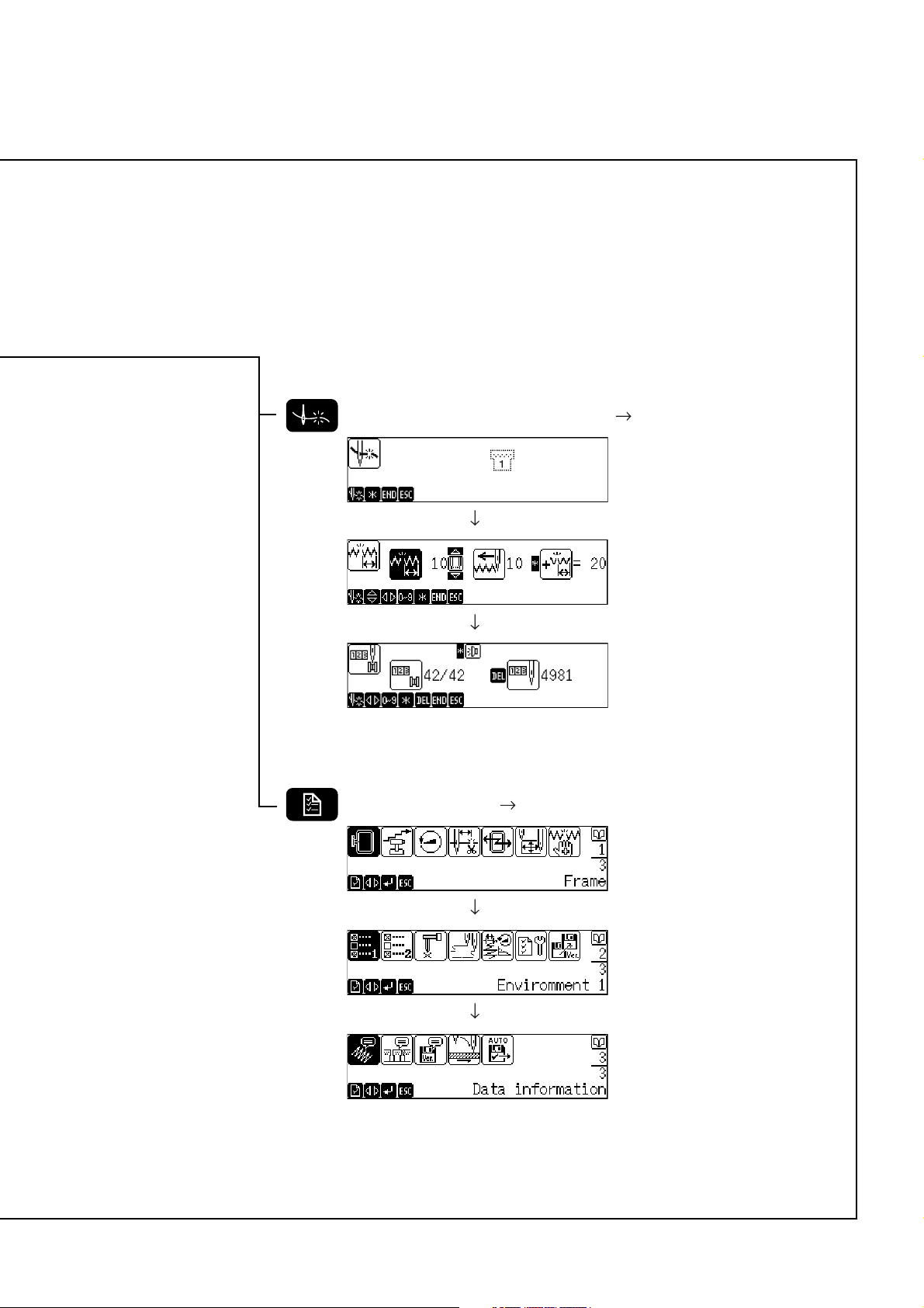
Rotation
A pattern can be rotated.
A maximum range of rotation is 1 ~ 359 degrees.
The rotating direction is counterclockwise.
Rotating angle can be set in either of the following.
Chapter 4 Editing of Embroidering Data
By using Angle can be specified in increments of 90˚. Setting of 90˚,180˚
By using ten keys Angle can be specified in increments of one degree.
1. Read sewing data.
2. Press
3. Press
4. Press
The initial screen is displayed again.
.
to select an angle or use ten keys to specify an angle.
END
.
or 270˚ is available.
BES-116AC
63
Page 66

Chapter 4 Editing of Embroidering Data
Enlargement and Reduction
A pattern can be enlarged or reduced.
The enlargement and reduction ratio is 50 ~ 200%.
The number of stitches does not change even by enlargement or reduction of a
pattern. However, stitches may become too rough or close if enlargement or
reduction is excessive.
There are the following two types of enlargement/reduction.
• Enlargement/reduction at the same ratio in both the X and Y directions
• Enlargement/reduction at different ratios in the X and Y directions
1. Read sewing data.
2. Press
.
Enlargement/reduction at the same ratio in the X/Y directions
3. Press .
are reversed in black.
4. Input enlargement/reduction ratio by pressing ten keys.
5. Press
The initial screen is displayed again.
64
END
.
BES-116AC
Page 67

Chapter 4 Editing of Embroidering Data
Enlargement/reduction at different ratios in the X/Y directions
3. Press twice.
is reversed in black.
4. Input enlargement/reduction ratio in the X direction by pressing ten keys.
5. Press .
is reversed in black.
6. Input enlargement/reduction ratio in the Y direction by pressing ten keys.
7. Press
The initial screen is displayed again.
END
.
BES-116AC
65
Page 68

Chapter 4 Editing of Embroidering Data
Mirror
A pattern can be reversed as if it is reflected in the mirror.
Right/left mirror pattern
Up/down mirror pattern
Zero point-symmetric mirror pattern
Up/down mirror pattern Right/left mirror pattern Zero point-symmetric mirror
pattern.
Right/left mirror pattern The pattern is reversed in the right/left
direction on the basis of the embroidering
start point.
Up/down mirror pattern The pattern is reversed in the up/down
direction on the basis of the embroidering
start point.
Zero point-symmetric mirror pattern The pattern is reversed on the basis of
the embroidering start point.
1. Sewing data is read.
2. Press
.
66
BES-116AC
Page 69

Right/Left Mirror Pattern
3. Keep pressing until is displayed.
Chapter 4 Editing of Embroidering Data
4. Press
The initial screen is displayed again.
END
.
Up/Down Mirror Pattern
3. Keep pressing until is displayed.
4. Press
The initial screen is displayed again.
END
.
Zero Point-Symmetric Mirror Pattern
3. Keep pressing until is displayed.
4. Press
The initial screen is displayed again.
END
.
BES-116AC
67
Page 70

Chapter 4 Editing of Embroidering Data
Repetition
A pattern is repeatedly copied as many times as specified.
The number of repetitions is 1 ~ 99 in both the vertical (row) and horizontal (line)
directions.
There are the following eight directions of repetitions.
Horizontal direction from upper left to lower right
Vertical direction from upper right to lower left
Horizontal direction from lower right to upper left
Vertical direction from lower right to upper left
Vertical direction from lower left to upper right
Horizontal direction from upper right to lower left
Vertical direction from upper left to lower right
Horizontal direction from lower left to upper right
There are the following two types of intervals between repetitions.
By setting a distance between the outer hoops of each pattern
By setting a distance between the centers of each pattern
1. Read sewing data.
2. Press
twice.
3. Input the number of repetitions in the vertical and horizontal directions,
by pressing ten keys.
The vertical and horizontal directions are changed over by pressing .
68
BES-116AC
Page 71

Chapter 4 Editing of Embroidering Data
4. Press .
5. Input intervals between repetitions by pressing ten keys.
The vertical and horizontal directions are changed over by pressing .
Press for setting a distance between the centers of each pattern.
For setting a distance between the outer
hoops of each pattern
For setting a distance between the centers
of each pattern
6. Select the direction of repetitions by pressing .
7. Press
The initial screen is displayed again.
END
.
BES-116AC
69
Page 72

Chapter 4 Editing of Embroidering Data
Other Editing
Setting of other functions related to editing is available.
The following types of setting is available.
0 stitch deletion For deleting stitches at the same point without
Thread trimming feed number For setting the number of feeds for thread trimming
stepping forward or back.
This function is previously set to
0stitch)upon shipment.
For deleting 0 stitch
For not deleting 0 stitch
This function is previously set to (ECS data)
or
(Except ECS data)upon shipment.
~ For thread trimming at the number of feeds
indicated on the icon
For not thread trimming by feeding
(for not deleting
Swing width correction
For setting the needle swing width correction amount
The correction amount can be set in increments of 0.1mm.
The setting range is -0.5 ~ 2.0mm in both the X and
Y directions. (The setting range is displayed as "-5
~ 20" on the screen.)
This function is previously set to 0(no swing width
correction)upon shipment.
1. Read sewing data.
2. Press
three times.
0 Stitch Deletion
3. Select this function by pressing .
4. Press
Press when setting continuously.
70
END
after setting is finished.
BES-116AC
Page 73

Chapter 4 Editing of Embroidering Data
Thread Trimming Feed Number
3. Select this function by pressing .
4. Select the number of feeds by pressing .
5. Press
END
after setting is finished.
Sewing Width Correction
Correction values within -5 ~ 20 can be input. However, excessively large values
may result in distortion of a pattern.
3. Select this function by pressing
4. Select a correction amount in the X direction by pressing .
.
5. Reverse by pressing .
6. Input a correction amount in the Y direction by pressing .
BES-116AC
71
Page 74

Chapter 4 Editing of Embroidering Data
7. Press
END
after setting is finished.
Press when setting continuously.
72
BES-116AC
Page 75

Chapter 5 Setting
This Chapter describes how to set a sewing
speed, correct trouble including thread breakage and others related to machine motions.
Page 76

Chapter 5 Setting
What Can the Machine Do?
Setting of Needle Bars
Needle bars allocated in the sequence of embroidering ( Page 76)
Setting of Thread Breakage Sensor
Thread breakage sensor ON/OFF ( Page 78)
Thread breakage sensitivity ( Page 78)
Number of stitches in automatic step back ( Page 79)
Display of total stitch number in automatic step back
Lower thread counter counts ( Page 80)
Stitch counter indication ( Page 80)
Setting of Machine
Selection of embroidery hoop ( Page 81)
Speed range ( Page 82)
Speed in speed range ( Page 83)
Thread trimming length ( Page 85)
Thread removal feed length ( Page 85)
Inching ON/OFF ( Page 86)
Sewing area ( Page 87)
Resetting of thread breakage error ( Page 84)
Setting of Environment
Return to start point after embroidering end ( Page 90)
Method of reflecting modified machine speed ( Page 90)
Method of checking the embroidery area ( Page 91)
Feed rate adjustment ( Page 92)
Data transfer speed ( Page 92)
Display language ( Page 93)
Alarm sound ( Page 94)
Motive speed ( page 95)
Small-pitch deletion ( Page 96)
XY Feed Power ( Page 96)
74
BES-116AC
Page 77

Setting of Boring
Boring mode ON/OFF ( page 98)
Data shift ON/OFF ( page 99)
Setting of Lock Stitch
Lock stitch ON/OFF (sewing start position) ( page 99)
Lock stitch ON/OFF (sewing send position) ( page 100)
Lock stitch ON/OFF (sewing start position after thread trimming) ( page 101)
Setting of speed limit in a small pitch
Speed limit in a short pitch ( page 102)
Chapter 5 Setting
Display of Information
Display of pattern information ( Page 107)
Features of machine ( Page 108)
Version information ( Page 109)
Feed timing ( Page 103)
Automatic input setting ( Page 104)
Hoop Retract Point
Hoop Movement
Registration of embroidering start point ( Page 88)
Hoop retract point ( Page 88)
Automatic hoop retract ON/OFF ( Page 89)
Movement to registered sewing start point ( Page 89)
BES-116AC
75
Page 78

Chapter 5 Setting
Setting of Needle Bars
Needle bars allocated in the sequence of sewing can be modified.
BES-116AC is not equipped with needle bar change mechanism. However, the
following procedure is available to input reference information about color
changes.
Either feedhold or hoop retract can be inserted.
1. Press
2. Select a sewing sequence to modify by pressing
The current embroidering sequence is selected while embroidering is interrupted.
Press for modifying all sequences at one time.
.
.
3. Input the number of a needle bar by pressing ten keys.
When inputting a numerical figure exceeding 10, press the
SPACE
0
first.
76
Insertion of Feedhold
Press and reverse the display on the right of a point to insert a feedhold, then
press
4. Press
Modified setting is saved and the previous screen is displayed again.
STOP
.
A feedhold mark is displayed.
END
.
BES-116AC
Page 79

Chapter 5 Setting
Insertion of Hoop Retract
1. Press to highlight the position right next to the position to insert the
hoop retract and press
.
2. Press the
The changed setting is stored and the previous screen is displayed.
END
button.
BES-116AC
77
Page 80

Chapter 5 Setting
Thread Breakage Sensor
Validity or invalidity and sensitivity of the thread breakage sensor can be set.
Setting of sensor validity/invalidity
This function is previously set to valid upon shipment.
END
.
.
Valid Invalid
.
1. Press
2. Activate or deactivate the thread breakage sensor by pressing
3. Press
Modified setting is saved and the initial screen or halt screen is displayed again.
Thread Breakage Sensitivity
Sensitivity of the thread breakage sensor can be set.
The sensitivity can be set within the range of 1 ~ 100. Sensitivity increases as
the figure decreases.
This function is previously set to 10 upon shipments.
1. Press
twice.
2. Select the needle bar for which the sensitivity is modified by pressing
.
The number of needle bars changes in the sequence of :
ALL (all needle bars)
1 2 ... 9 or 12 (max.) ALL ...
3. Select by pressing .
4. Input sensitivity of the thread breakage sensor.
5. Press
Modified setting is saved and the previous screen is displayed again.
END
.
78
BES-116AC
Page 81

Chapter 5 Setting
Automatic Step-Back
The number of stitches to step back automatically in case of a thread breakage can
be set.
Setting can be done within the range of 0 ~ 10 stitches.
This function is previously set to 0 stitches upon shipments.
1. Press
2. Select
twice.
by pressing .
3. Input the number of stitches to step back automatically by pressing ten
keys.
Pressing sets whether to execute an extra step-back by a sensitivity amount of the thread
breakage sensor in the automatic step-back mode.
Total number of stitches to step back in
the automatic step-back mode
When stepping back by a sensitivity
amount of the thread breakage sensor
When stepping back by preset number of
stitches
4. Press
Modified setting is saved and the previous screen is displayed again.
END
.
BES-116AC
79
Page 82

Chapter 5 Setting
Setting of Lower Thread Counter/Stitch Counter
The lower thread counter reduces the indication each time one pattern is finished.
After the reduction is finished, an error message can be displayed.
The stitch counter increases the indication stitch by stitch.
The lower thread counter can be validated or invalidated by pressing .
The stitch counter can be cleared to zero by pressing
DEL
.
1. Press
three times.
2. Input the number of counts of the lower thread counter by pressing ten
keys.
Number of stitches
3. Press
Modified setting is saved and the initial screen or halt screen is displayed again.
END
.
80
BES-116AC
Page 83

Setting of Machine
Machine motions can be set.
Embroidery Hoop
Specify a type of an embroidery hoop set on the machine.
A type of a hoop can be selected when a cap hoop or an air clamp hoop is
selected by a switch on the operation panel.
When a cap hoop is selected Semi-wide cap frame
When an air clamp hoop is L hoop
selected
Chapter 5 Setting
Wide cap frame
Baseball cap frame
M hoop
S hoop
VL hoop
An air clamp hoop is available as an option. For the description of usage, refer to
the accompanying instruction manual.
1. Press
2. Select
.
by pressing .
3. Press .
4. Select a type of a hoop by pressing
.
Currently selected hoop
5. Press
Modified setting is saved and the previous screen is displayed again.
END
.
BES-116AC
81
Page 84

Chapter 5 Setting
Speed Range
A range of speed for each needle bar can be set.
BES-116AC is not equipped with needle bar change mechanism. When setting
thread color in a sequence, a speed range can be specified for each color.
The speed range can be set within the range of 1 ~ 6.
1. Press
2. Select
.
by pressing .
3. Press .
4. Select a needle bar by pressing .
When setting the same speed range for all needle bars, press .
When modifying the speed range for one
needle bar
82
When modifying the speed range for all
needle bars
5. Input a required speed range by pressing ten keys.
6. After modification is finished, press
Modified setting is saved and the previous screen is displayed again.
BES-116AC
END
.
Page 85

Chapter 5 Setting
Speed of Each Speed Range
Maximum speed of each range can be set.
Speed can be input in increments of 10rpm.
The upper limit of a speed to be set varies depending on a selected hoop.
1. Press
2. Select
.
by pressing .
3. Press .
4. Select a speed range to modify by pressing .
Upper limit of speed to be set in each range
Maximum speed
Lowest speed
5. Input a required speed by pressing ten keys.
6. After modification is finished, press
Modified setting is saved and the previous screen is displayed again.
END
.
BES-116AC
83
Page 86

Chapter 5 Setting
Setting of Mending
Details of mending can be set in case of a thread breakage.
Contents of each setting item are as described below.
Item Contents
For setting whether to reset a thread breakage error automatically
This function is previously set to (Manual) upon shipments.
For resetting an error automatically
For resetting an error manually
1. Press .
2. Select
by pressing .
3. Press .
4. Press for modifying a resetting method.
5. Press
Modified setting is saved and the initial screen is displayed again.
END
.
Thread Trimming Length
Length of thread to leave on the needle bar after thread trimming can be set for
each needle bar.
Thread trimming length can be set within the range of 1~ 6.
This function is previously set to 4 upon shipments.
1. Press .
84
BES-116AC
Page 87

2. Select by pressing .
3. Press .
4. Select a needle bar to modify by pressing .
Press for setting the same speed range for all needle bars.
Chapter 5 Setting
5. Input thread length by pressing ten keys.
Thread length can be input within the range of 1 ~ 6. Length decreases as the figure decreases.
6. After setting is finished with all needle bars, press
Modified setting is saved and the previous screen is displayed again.
END
.
Thread Withdrawal Feed Length
Thread withdrawal length can be set before thread trimming.
The input range is 0 ~ 100mm.
This function is previously set to 15mm upon shipments.
1. Press
.
2. Select
by pressing .
BES-116AC
85
Page 88

Chapter 5 Setting
3. Press .
4. Input thread withdrawal length by pressing ten keys.
5. Press
Modified setting is saved and the previous screen is displayed again.
END
.
Inching
Whether to select the inching mode for thread trimming can be set.
This function is previously set to selected upon shipments.
1. Press .
2. Select
3. Press .
by pressing .
4. Set whether to select the inching mode by pressing .
5. Press
Modified setting is saved and the previous screen is displayed again.
86
END
.
BES-116AC
Page 89

Sewing Area
An allowable area for sewing can be set.
A maximum sewing area using a flat hoop is as shown below.
450mm
(0, 0)
1
(300mm)
2
(450, 300)
1. Press .
Chapter 5 Setting
2. Select
by pressing .
3. Press .
4. Specify coordinates of the upper left of the sewing area. Move the hoop
by pressing
.
Indicates a currently set embroidery area
5. Press .
Pressing set a maximum area designated for a currently set hoop.
6. Specify coordinates of the lower right of the sewing area. Move the hoop
by pressing
7. Press
Pressing restores a status before modification of setting.
END
.
.
BES-116AC
87
Page 90

Chapter 5 Setting
Registration of Sewing Start Position
Register a position to start sewing.
When returning to a registered sewing start position, hold down
and press
STOP
.
1. Press the
The hoop coordinates are displayed.
key.
2. Shift the hoop to a position to start sewing by pressing the .
3. Press
4. Press the
END
.
key.
Hoop Retract Point
The hoop basic point (retract point) can be set when sewing is interrupted.
When restarting sewing after the hoop is retracted during an interrupt, press .
1. Press .
2. Move the hoop by pressing
Current hoop coordinates
3. Press
Modified setting is saved and the initial screen or halt screen is displayed again.
The hoop returns to the initial point.
END
.
Cancellation of Setting
1. Press once again.
Modified setting is canceled and the initial screen or halt screen is displayed again. The hoop
returns to the initial point.
.
88
BES-116AC
Page 91

Chapter 5 Setting
Hoop Automatic Retract
Set whether to move the hoop automatically to the retract point at the end of sewing.
This function is previously set to no hoop automatic retract upon shipments.
1. Press
.
2. Select whether to retract the hoop automatically by pressing
For automatically retracting the hoop
For not retracting the hoop automatically
3. Press
Modified setting is saved and the initial screen or halt screen is displayed again.
END
.
Movement to Registered Sewing Start Point
This operation should be done before starting sewing.
.
1. Hold down
and press .
STOP
2. The hoop moves and the zero point is detected. Then the hoop moves to
a registered start point.
3. The initial screen is displayed again.
BES-116AC
89
Page 92

Chapter 5 Setting
Setting of Environment
Return to Start Point
Whether to return to the start point after sewing is finished can be set.
1. Press
2. Select
twice.
by pressing .
3. Press .
4. Select
by pressing .
5. Select whether to validate a return to the start point by pressing .
When the start point return is valid
90
When the start point return is invalid
6. Press
Modified setting is saved and the previous screen is displayed again.
END
.
Speed Range
For setting whether to reflect modified machine speed to all needle bars.
1. Press
2. Select
3. Press .
twice.
by pressing .
BES-116AC
Page 93

4. Select by pressing .
ESC
5. Modify setting by pressing .
Press
ESC
for invalidating the modification.
Chapter 5 Setting
6. Press
Modified setting is saved and the previous screen is displayed again.
END
.
Checking the Embroidery Area
The embroidery area can be checked according to the following procedure.
The following two checking methods (rectangle and octagon) can be selected.
Item Contents
Checking by rectangle tracing
Checking by octagon tracing
1. Press twice.
2. Select
with .
3. Press .
4. Press
to select .
5. Press to change the settings.
Checking with the rectangle
Checking with the octagon
6. Press
The changed settings are stored and the previous screen is displayed.
END
.
BES-116AC
91
Page 94

Chapter 5 Setting
Feed rate adjustment
A feed rate is adjustable.
A feed rate can be set in the range of "1 (normal)" to "5 (slow)".
This function is previously set to "1" upon shipment.
1. Press
2. Select
twice.
with .
3. Press .
4. Select the desired feed rate with
5. Press
The new feed rate is saved. The previous screen appears.
END
.
.
Setting of RS-232C Communication Speed
Speed for transferring embroidery data between the operation panel and a personal
computer with BE-100 installed.
The transmission speed can be selected within the range of 9600, 19200, 38400
and 115200. (unit : bps)
1. Press
2. Select
twice.
by pressing .
3. Press .
92
BES-116AC
Page 95

4. Select [RS Speed] by pressing .
5. Select cpmmunication speed by pressing .
END
6. Press
Modified setting is saved and the previous screen is displayed again.
.
Display Language
A language to display on the screen can be set.
Chapter 5 Setting
The following languages can be selected.
Display Contents
JPN Japanese
Eng English
Españl Spanish
fr. French
1. Press twice.
2. Select
by pressing .
3. Press .
4. Select [Language] by pressing .
BES-116AC
93
Page 96

Chapter 5 Setting
5. Select a language to display by pressing .
6. Press
The previous screen is displayed again with a display in a selected language.
END
.
Alarm Sound
Whether to generate a sound in case of an error can be set.
The following sounds can be set.
ON A sound is generated until the error is reset.
OFF A sound is generated twice.
5 A sound is generated five times.
1. Press twice.
2. Select
by pressing .
3. Press .
4. Select [Beep] by pressing .
5. Select a kind of sound by pressing .
6. Press
Modified setting is saved and the previous screen is displayed again.
END
.
94
BES-116AC
Page 97

Motive Speed
The startup speed of the main shaft can be set.
The following startup speed can be set.
NOMAL Starts up the main shaft at the normal speed.
UP Speeds up the startup speed of the main shaft.
CAP Speeds up the startup speed of the main shaft when using the cap frame.
FLAT Speeds up the startup speed of the main shaft when using a frame other
than the cap frame.
1. Press twice.
Chapter 5 Setting
2. Select
with .
3. Press .
4. Select "Motive Speed" with .
5. Select the type of the startup speed of the main shaft with .
6. Press the
The changed settings are stored and the previous screen is displayed.
END
button.
BES-116AC
95
Page 98

Chapter 5 Setting
Small-Pitch Deletion
Stitches less than preset can be deleted.
Settings in the range of OFF to 1.0 mm (in units of 0.1 mm) are valid. When OFF
is chosen, stitch deletion is not carried out.
This function is previously set to "OFF" upon shipment.
1. Press
2. Select
twice.
with .
3. Press .
4. Select "Del. small stch" with .
5. Select the maximum stitch to be deleted with .
6. Press
The new setting is saved and calculation is performed. The previous screen is displayed.
For example, if 0.3 mm is set, stiches shorter than 0.3 mm are deleted.
96
END
.
BES-116AC
Page 99

Chapter 5 Setting
XY Feed Power Increase
The frame movement power for positioning before starting embroidering can be
switched.
The following settings can be set.
NOMAL Frame movement at normal power. (by the jog switches)
UP Frame movement at increased power (by the jog switches)
This setting is not valid to the frame feed during embroidering.
1. Press
2. Select
twice.
with .
3. Press .
4. Select "XY power" with .
5. Select the XY feed power with .
6. Press
The new setting is saved and the previous screen is displayed.
END
.
BES-116AC
97
Page 100

Chapter 5 Setting
Boring
Whether to validate or invalidate the boring mode and to shift data in case of boring
can be set.
This setting is available only for sewing data which has been created for boring.
The machine itself cannot check if the sewing data is for boring or not. Therefore,
make sure to check the data before starting sewing.
Mount the following optional accessories on the machine before starting sewing.
• Boring knife
• Needle plate for boring, Finger guard
If editing including enlargement, reduction or rotation is done using sewing data
created for boring, the correct sewing may not be available.
This function is previously set to :
• Boring mode valid/invalid : invalid
• Data shift valid/invalid : invalid
Validation/Invalidation of Boring Mode
1. Press twice.
2. Select
3. Press .
4. Select by pressing .
by pressing .
5. Validate or invalidate the boring mode by pressing .
When the boring mode is valid
When the boring mode is invalid
98
BES-116AC
 Loading...