

Page 1

FACSIMILE EQUIPMENT
SERVICE MANUAL
MODEL: FAX1170/1270/1570MC
FAX1010/1020/1030
MFC1770/1870MC/1970MC
Page 2

© Copyright Brother 1997
All rights reserved.
No part of this publication may be reproduced in any
form or by any means without permission in writing
from the publisher.
Specifications are subject to change without notice.
Page 3

PREFACE
This publication is a Service Manual covering the specifications, construction, theory of operation, and maintenance of the Brother facsimile equipment. It includes information required for
field troubleshooting and repair—disassembly, reassembly, and adjustment—so that service
personnel will be able to understand equipment function, to rapidly repair the equipment and
order any necessary spare parts.
To perform appropriate maintenance so that the facsimile equipment is always in best condition
for the customer, the service personnel must adequately understand and apply this manual.
This manual is made up of six chapters and appendices.
CHAPTER I. GENERAL DESCRIPTION
CHAPTER II. INSTALLATION
CHAPTER III. THEORY OF OPERATION
CHAPTER IV. DISASSEMBL Y/REASSEMBLY AND LUBRICATION
CHAPTER V. MAINTENANCE MODE
CHAPTER VI. ERROR INDICATION AND TROUBLESHOOTING
APPENDICES Circuit Diagrams
This manual describes the model and its versions to be destined for major countries. The specifications
and functions are subject to change depending upon each destination.
Page 4

CHAPTER I.
GENERAL DESCRIPTION
Page 5

CONTENTS
1. EQUIPMENT OUTLINE ................................................................................. I-1
1.1 External Appearance and Weight........................................................... I-1
1.2 Components............................................................................................ I-1
2. SPECIFICATIONS .......................................................................................... I-2
Page 6
1. EQUIPMENT OUTLINE
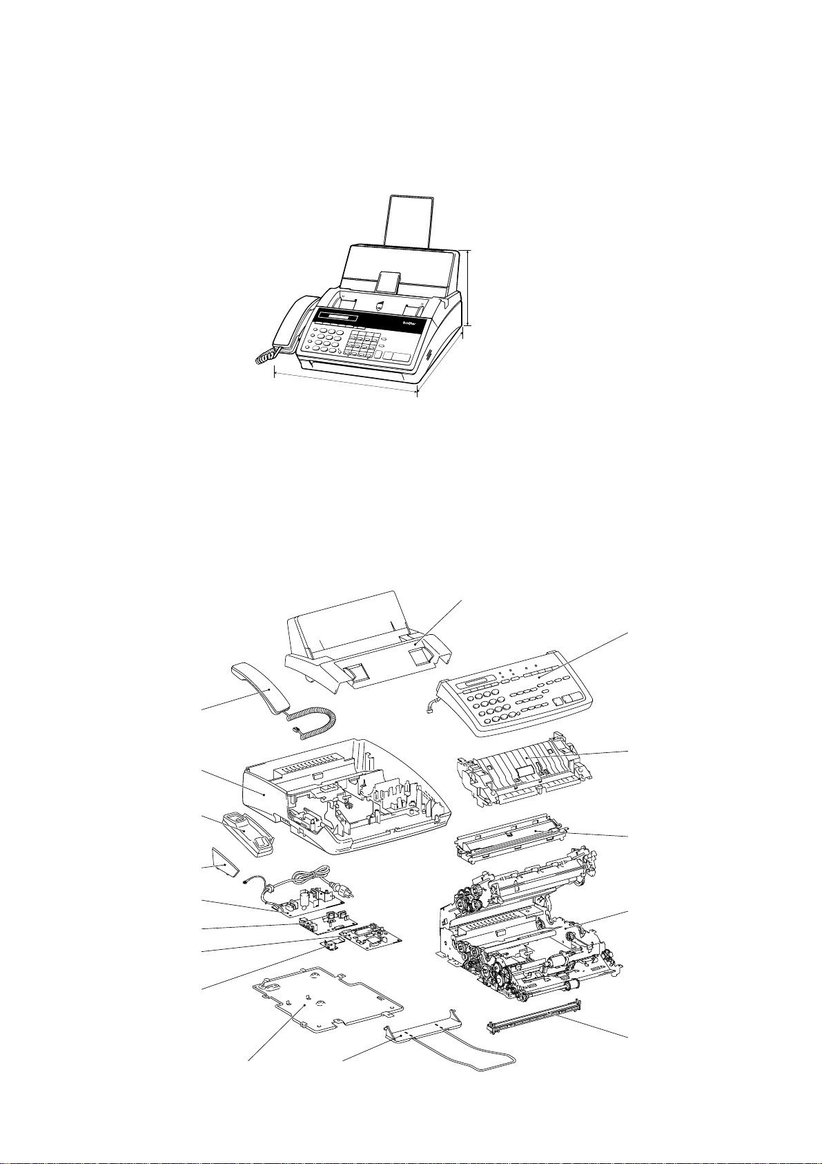
1.1 External Appearance and Weight
The figure below shows the equipment appearance and approximate dimensions.
(Unit: mm)
Weight: Machine proper FAX1010: Approx. 5.0 kg (excluding a ribbon cartridge)
In package FAX1010: Approx. 8.7 kg
1.2 Components
The equipment consists of the following major components:
8.5"
A4
Function
Tel/Index
Resolution
Super
Mode
O. Scan
Hook
Hold
Redial/Pause
PRS
7
Speed Dial
*
Help
ABC
DEF
1
2
01
02
3
GHI
4
8
0
03
JKL
5
TUV
#
04
13
MNO
14
15
16
6
05
06
07
WXYZ
08
17
18
9
19
20
09
10
11
Copy
Shift
12
21
22
23
24
Set
Clear
A4
8.5"
IntelliFAX -1270
PLAIN PAPER FACSIMILE
Sort
Enlarge/
Reduce
Stop
Start
213 (H)
385 (D)
* 317 mm for FAX1010 which has
385.5 (W)*
no handset mount
Other models: Approx. 5.2 kg (excluding a ribbon cartridge)
Other models: Approx. 8.9 kg
Recording paper cover ASSY
Control panel
ASSY
Handset
(Not provided on
the FAX1010)
Main cover
Handset mount
(Not provided on
the FAX1010)
Side cover
(Provided only on
the FAX1010)
Power supply PCB
NCU PCB
Main PCB
Modular PCB
Bottom plate
Inner cover
Recording head
ASSY
Main frame
CIS unit
Document
ejection tray
I – 1
Page 7

2. SPECIFICATIONS
Model FAX1170 FAX1270 FAX1570MC
Color Gray (1395) White (1397) White (1397)
Modem Speed 9600 bps 9600 bps 14400 bps
CCITT Group G3 G3 G3
Coding Method MH MH MH
Transmission Speed 15 sec. 15 sec. 9 sec.
Input/Output Width 8.5"/8.5" 8.5"/8.5" 8.5"/8.5"
ADF Capacity (pages) 20 20 20
Recording Paper Loadable 200 sheets 200 sheets 200 sheets
Paper Size Letter/Legal/A4 Letter/Legal/A4 Letter/Legal/A4
Ribbon Life (Letter-size print) 450 pages 450 pages 450 pages
Handset Yes Yes Yes
LCD Size 16 x 1 16 x 1 16 x 1
On-screen Programming Yes Yes Yes
Gray Scale 64 by Dithered 64 by Dithered 64 by E/D
Smoothing Yes Yes Yes
One-touch Dial 12 x 2 12 x 2 12 x 2
Speed Dial 26 36 100
Telephone Index Yes Yes Yes
Multi-resolution Transmission
FAX/TEL Switch Yes Yes Yes
Distinctive Ringing Yes Yes Yes
Next Fax-reservation Yes Yes Yes
Help Yes Yes Yes
TAD Interface Yes Yes Yes
Coverpage Yes, Super Yes, Super Yes, Super
Polling Type Sim/Del/Seq Sim/Del/Seq Sim/Del/Seq
Receive Password (password plus)
Delayed Transmission 3, timers 3, timers 3, timers
Call Reservation Yes Yes Yes
Call-back Message Yes Yes Yes
Speaker Phone Monitor Monitor Yes, Full-duplex
Activity Report Yes Yes Yes
Transmission Verification Report
Page Memory 512 KB (20 pages) 512 KB (20 pages) 1 MB (50 pages)
Out-of-paper Reception Yes Yes Yes
Quick Scan Yes Yes Yes
Super Quick Scan No No No
Broadcasting Yes Yes Yes
ECM Yes Yes Yes
Multi-transmission Yes Yes Yes
Multi-copying w/Sorting Yes Yes Yes
Enlargement/Reduction Ratio Yes (50-150%) Yes (50-150%) Yes (50-150%)
TAD Type No No DSP
OGM No No Yes
ICM Recording Time No No Yes, 30 min.
FAX Forwarding/Paging No Yes Yes
FAX Retrieval No Yes Yes
PCI (Missing link) Ready Ready Ready
Message Center No No Yes
Caller ID Yes Yes Yes
Fax-/Voice-on-demand No No Voice-on-demand
Mail Box No No Yes
Remote Control Yes Yes Yes
Toll Saver No No Yes
Memo/2-Way Recording No No Yes
Auto Reduction Yes Yes Yes
Confidential Mailbox No No No
Optional Memory No No No
Yes Yes Yes
Yes Yes Yes
Yes Yes Yes
I – 2
Page 8

Model FAX1010 FAX1020 FAX1030
Color White (1138) White (1138) White (1138)
Modem Speed 9600 bps 9600 bps 14400 bps
CCITT Group G3 G3 G3
Coding Method MH MH MH
Transmission Speed 15 sec. 15 sec. 10 sec.
Input/Output Width A4/A4 A4/A4 A4/A4
ADF Capacity (pages) 20 20 20
Recording Paper Loadable 200 sheets 200 sheets 200 sheets
Paper Size Letter/Legal/A4 Letter/Legal/A4 Letter/Legal/A4
Ribbon Life (A4-size print) 420 pages 420 pages 420 pages
Handset No Yes Yes
LCD Size 16 x 1 16 x 1 16 x 1
On-screen Programming Yes Yes Yes
Gray Scale 64 by Dithered 64 by Dithered 64 by E/D
Smoothing Yes Yes Yes
One-touch Dial 12 x 2 12 x 2 12 x 2
Speed Dial 36 36 100
Telephone Index Yes (Not Super) Yes (Not Super) Yes (Not Super)
Multi-resolution Transmission
FAX/TEL Switch Yes Yes Yes
Distinctive Ringing Yes Yes Yes
Next Fax-reservation Yes Yes Yes
Help Yes, Simple Yes, Simple Yes, Simple
TAD Interface Yes Yes Yes
Coverpage Yes, Super Yes, Super Yes, Super
Polling Type Std/Sec/Del/Seq Std/Sec/Del/Seq Std/Sec/Del/Seq
Receive Password (password plus)
Delayed Transmission 3, timers 3, timers 3, timers
Call Reservation Yes Yes Yes
Call-back Message Yes Yes Yes
Speaker Phone Monitor Monitor Yes, Full-duplex
Activity Report Yes Yes Yes
Transmission Verification Report
Page Memory 512 KB (20 pages) 512 KB (20 pages) 1 MB (50 pages)
Out-of-paper Reception Yes (20 pages) Yes (20 pages) Yes (50 pages)
Quick Scan Yes (18 pages) Yes (18 pages) Yes (18 pages)
Super Quick Scan No No No
Broadcasting Yes, 60 locations Yes, 60 locations Yes, 124 locations
ECM Yes Yes Yes
Multi-transmission Yes Yes Yes
Multi-copying w/Sorting Yes Yes Yes
Enlargement/Reduction Ratio Yes (50-150%) Yes (50-150%) Yes (50-150%)
TAD Type No No DSP
OGM No No Yes
ICM Recording Time No No Yes, 30 min.
FAX Forwarding/Paging Yes/No Yes/No Yes
FAX Retrieval Yes Yes Yes
PCI (Missing link) Ready Ready Ready
Message Center No No Yes
Caller ID
Fax-/Voice-on-demand No No Voice-on-demand
Mail Box No No Yes, 5
Remote Control Yes Yes Yes
Toll Saver No No Yes
Memo/2-Way Recording No No Yes
Auto Reduction Yes Yes Yes
Confidential Mailbox No No No
Optional Memory No No No
UK, Sw., Holland (Ready for France) UK, Sw., Holland (Ready for France) UK, Sw., Holland (Ready for France)
Yes Yes Yes
Yes Yes Yes
Yes Yes Yes
I – 3
Page 9

Model MFC1770 MFC1870MC MFC1970MC
Color White (1138) White (1138) White (1138)
Modem Speed 9600 bps 14400 bps 14400 bps
CCITT Group G3 G3 G3
Coding Method MH MH MH
Transmission Speed 15 sec. 9 sec. 9 sec.
Input/Output Width 8.5"/8.5" 8.5"/8.5" 8.5"/8.5"
ADF Capacity (pages) 20 20 20
Recording Paper Loadable 200 sheets 200 sheets 200 sheets
Paper Size Letter/Legal/A4 Letter/Legal/A4 Letter/Legal/A4
Ribbon Life (Letter-size print) 450 pages 450 pages 450 pages
Handset Yes Yes Yes
LCD Size 16 x 1 16 x 1 16 x 1
On-screen Programming Yes Yes Yes
Gray Scale 64 by Dithered 64 by Dithered 64 by E/D
Smoothing Yes Yes Yes
One-touch Dial 12 x 2 12 x 2 12 x 2
Speed Dial 36 36 100
Telephone Index Yes Yes Yes
Multi-resolution Transmission
FAX/TEL Switch Yes Yes Yes
Distinctive Ringing Yes Yes Yes
Next Fax-reservation Yes Yes Yes
Help Yes Yes Yes
TAD Interface Yes Yes Yes
Coverpage Yes, Super Yes, Super Yes, Super
Polling Type Sim/Del/Seq Sim/Del/Seq Sim/Del/Seq
Receive Password (password plus)
Delayed Transmission 3, timers 3, timers 3, timers
Call Reservation Yes Yes Yes
Call-back Message Yes Yes Yes
Speaker Phone Monitor Yes, Full-duplex Yes, Full-duplex
Activity Report Yes Yes Yes
Transmission Verification Report
Page Memory 512 KB (20 pages) 512 KB (20 pages) 1 MB (50 pages)
Out-of-paper Reception Yes Yes Yes
Quick Scan Yes Yes Yes
Super Quick Scan No No No
Broadcasting Yes Yes Yes
ECM Yes Yes Yes
Multi-transmission Yes Yes Yes
Multi-copying w/Sorting Yes Yes Yes
Enlargement/Reduction Ratio Yes (50-150%) Yes (50-150%) Yes (50-150%)
TAD Type No DSP DSP
OGM No Y es Yes
ICM Recording Time No Yes, 15 min. Yes, 30 min.
FAX Forwarding/Paging Yes Yes Yes
FAX Retrieval Yes Yes Yes
PCI (Missing link) Included (MFL3) Included (MFL3) Included (MFL3)
Message Center No Yes Yes
Caller ID Yes Yes Yes
Fax-/Voice-on-demand No Voice-on-demand Voice-on-demand
Mail Box No Yes Yes
Remote Control Yes Yes Yes
Toll Saver No Yes Yes
Memo/2-Way Recording No Yes Yes
Auto Reduction Yes Yes Yes
Confidential Mailbox No No No
Optional Memory No No No
Yes Yes Yes
Yes Yes Yes
Yes Yes Yes
I – 4
Page 10

CHAPTER II.
INSTALLATION
Page 11

CHAPTER III.
THEORY OF OPERATION
Page 12

CONTENTS
1. OVERVIEW..................................................................................................... III-1
1.1 Functional Block Diagram ...................................................................... III-1
2. MECHANISMS................................................................................................ III-2
2.1 Transmitting Mechanism (Feeding and scanning documents) ............... III-2
2.1.1 Automatic document feeder (ADF).................................................. III-2
2.1.2 Scanner ........................................................................................... III-3
2.2 Receiving Mechanism (Feeding paper and printing data)...................... III-4
2.3 Power Transmission Mechanism ........................................................... III-5
2.3.1 Structure of the gear train ............................................................... III-5
2.3.2 Description of planetary gear system.............................................. III-6
2.3.3 Power transmission for four operation modes................................. III-7
[ 1 ] Scanning mode (Solenoid: OFF, Motor rotation : Reverse)...................... III-8
[ 2 ] Paper feeding/ejection mode (Solenoid: ON, Motor rotation : Reverse) III-9
[ 3 ] Recording mode (Solenoid: OFF, Motor rotation : Forward) .................... III-10
[ 4 ] Copying mode (Solenoid: ON, Motor rotation : Forward) ......................... III-12
2.3.4 Power transmission route ............................................................... III-14
2.4 Sensors and Actuators........................................................................... III-16
3. CONTROL ELECTRONICS........................................................................... III-19
3.1 Configuration........................................................................................... III-19
3.2 Main PCB................................................................................................ III-20
3.3 NCU PCB................................................................................................ III-27
3.4 Control Panel PCB................................................................................. III-29
3.5 Power Supply PCB ................................................................................ III-30
Page 13
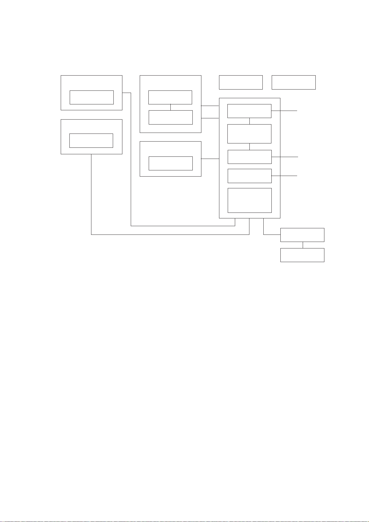
1. OVERVIEW
1.1 Functional Block Diagram
Control Panel
LCD
Scanner
CIS unit
Recorder
Recording head
Ribbon sensor
Main frame
Motor
Document
ejection tray
Modular PCB
(Cover sensor)
Main PCB
(Document front
and rear sensors)
NCU PCB
Power supply
PCB
Sensor PCB
(Paper-edge
sensor and paper
ejection sensor)
Ribbon cartridge
To PC
Line
AC
Handset
Hook switch
sensor
III – 1
Page 14
2. MECHANISMS
The equipment is classified into the following mechanisms:
■ Transmitting Mechanism Feeding and scanning documents
■ Receiving Mechanism Feeding paper and printing data
■ Power Transmission Mechanism Switching the power transmission route
■ Sensors and Actuators
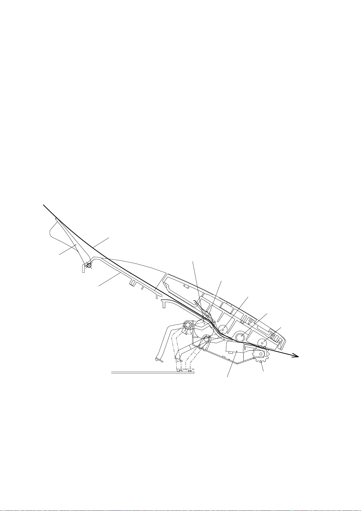
2.1 Transmitting Mechanism (Feeding and scanning documents)
The transmitting mechanism consists of the document stacker, automatic document feeder
(ADF), document feeding related rollers, scanner, and document sensors. (For details about
the sensors, refer to Section 2.4.)
For the drive power source, refer to Section 2.3.
Document
support
Document
stacker
Document
Separation roller
ADF parts
Scanner
(CIS unit)
Pressure roller,
rear
White pressure
roller
Pressure roller,
front
(Front)
Document
ejection roller
2.1.1 Automatic document feeder (ADF)
If the operator sets documents on the stacker and starts the transmitting operation, the ADF
(consisting of the separation roller and ADF parts) feeds those documents into the equipment, starting from the bottom sheet to the top, page by page. Each document advances to
the scanner, and then it is fed with the white pressure roller and document ejection roller.
III – 2
Page 15

2.1.2 Scanner
The scanner uses a contact image sensor (CIS) unit which consists of an LED array illuminating documents, a self-focus lens array collecting the reflected light, a CIS PCB carrying
out photoelectric conversion to output picture element data, and a cover glass on which a
document advances. When the document passes between the white pressure roller and the
cover glass, it is scanned.
III – 3
Page 16
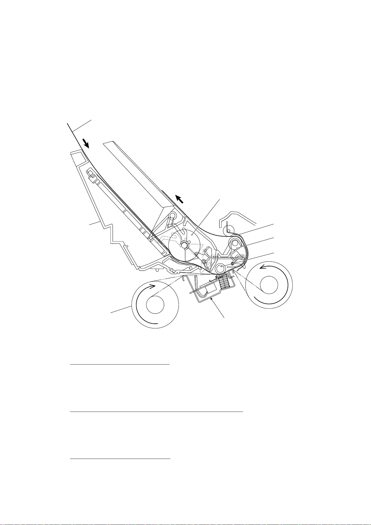
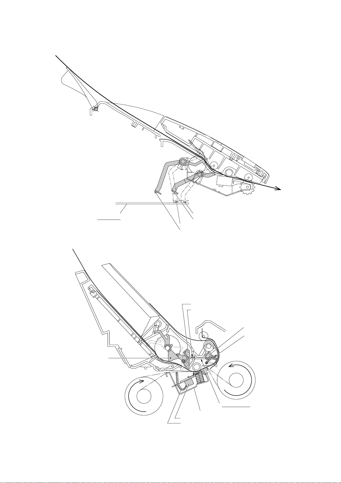
2.2 Receiving Mechanism (Feeding paper and printing data)
The receiving mechanism consists of the recording paper cover ASSY, paper feed roller
ASSY, platen, thermal recording head, paper ejection roller, and sensors. (For details about
the sensors, refer to Section 2.4.)
Paper
Paper feed roller ASSY
Recording
paper cover
ASSY
Thermal ink ribbon
Recording head
Chute ASSY
Paper ejection roller
Platen
STEP 1: In the paper feeding mode
If the equipment receives data, the control electronics activates the solenoid and rotates the
motor counterclockwise to drive the paper feed roller (and paper ejection roller). This pulls in
a sheet of paper and feeds it until its leading edge reaches the point just before the printing
position.
(Front)
STEP 2: In the recording (platen drive & ribbon take-up) mode
The control electronics deactivates the solenoid and rotates the motor clockwise to drive the
platen gear and the ribbon take-up gear as well as the paper ejection roller. This feeds the
paper up to the printing position where the thermal recording head prints, as well as feeding
the thermal ink ribbon.
STEP 3: In the paper ejecting mode
The same operation as for STEP 1 takes place so as to eject the paper.
III – 4
Page 17
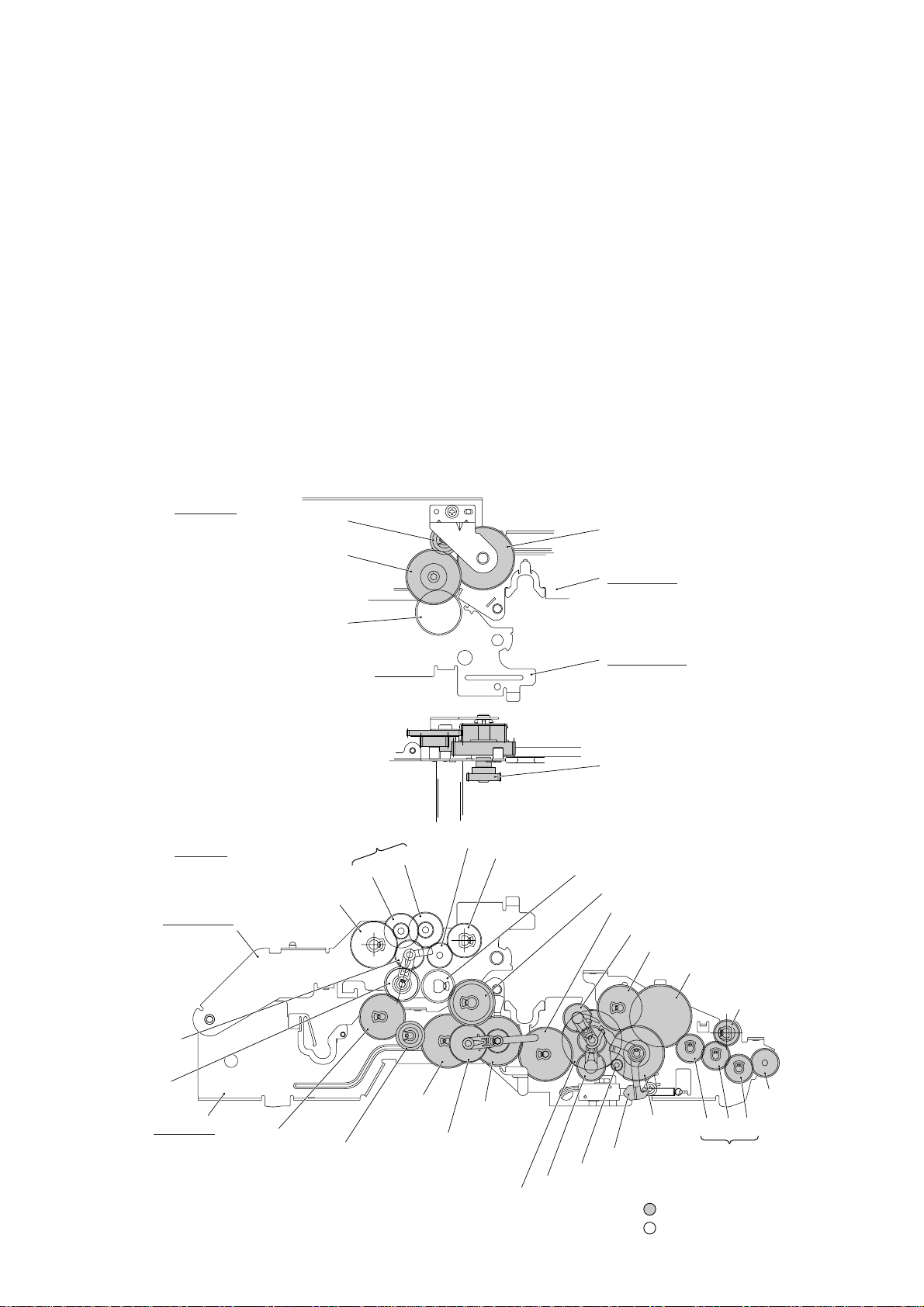
2.3 Power Transmission Mechanism
The equipment has a single drive motor whose power transmission route can be switched by
the planetary gear systems and the solenoid. This switching allows the equipment to function in four operation modes (scanning, paper feeding/ejecting, recording, and copying
modes). For the details about the planetary gear systems, refer to Subsection 2.3.2.
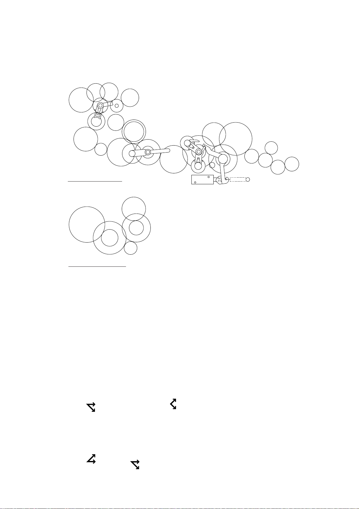
2.3.1 Structure of the gear train
At the left side of the equipment, the rotational torque of the motor on the main frame is
transmitted to the gears on the main frame and then to the gears on the platen frame. These
gears drive the document feeding/ejecting related rollers, paper feeding/ejecting related rollers, and the platen.
If the platen gear ("a" in the figure below) on the left end of the platen shaft rotates, the gear
33RB ("b") on the right end also rotates. This way, the rotational torque is transmitted to the
gears on the right side of the equipment.
At the right side of the equipment, the rotational torque is further transmitted via the friction
torque transmission ASSY to the ribbon drive gear ("e") which drives the ribbon take-up gear
in the ribbon cartridge.
Right side
d (Gear 18)
c (Gear 20/40)
b (Gear 33RB)
Left side
T (Paper feed roller gear, Gear 55)
Platen frame
(Gears 18/41)
e (Gear 46 of Friction torque
transmission ASSY)
Main frame
Platen frame
e (Ribbon drive gear, Gear 24)
W (Clutch gear ASSY)
V
U
X (Paper ejection roller gear, Gear 40)
a (Platen gear, Gear 23)
Z (Gear 33/45)
M (Gear 39)
C (Planet gear 20B of Arm B ASSY)
D (Gear 33)
F (Separation roller gear)
I (White pressure
roller gear)
S (Planet gear
34 of Arm P
ASSY)
R (Sun gear
39/24)
Main frame
Q (Gear 33)
P (Gear 18)
O (Gear 39)
Y (Planet gear 44 of
Arm C ASSY)
B (Sun gear 20/90)
Gear Train
III – 5
N (Sun gear
36/27)
E (Gear
20/40)
Clutch lever
A (Motor gear)
L (Planet gear 20A of Arm A ASSY)
G H J
: Gears on the main frame
: Gears on the platen frame
(Front)
K (Document
ejection roller
gear)
(Gears 14/20)
Page 18

2.3.2 Description of planetary gear system
The equipment uses the following three planetary gear systems:
- Sun gear 20/90 ("B" in the figure given on the previous page) and its planet gears
- Sun gear 36/27 ("N") and its planet gear
- Sun gear 39/24 ("R") and its planet gear
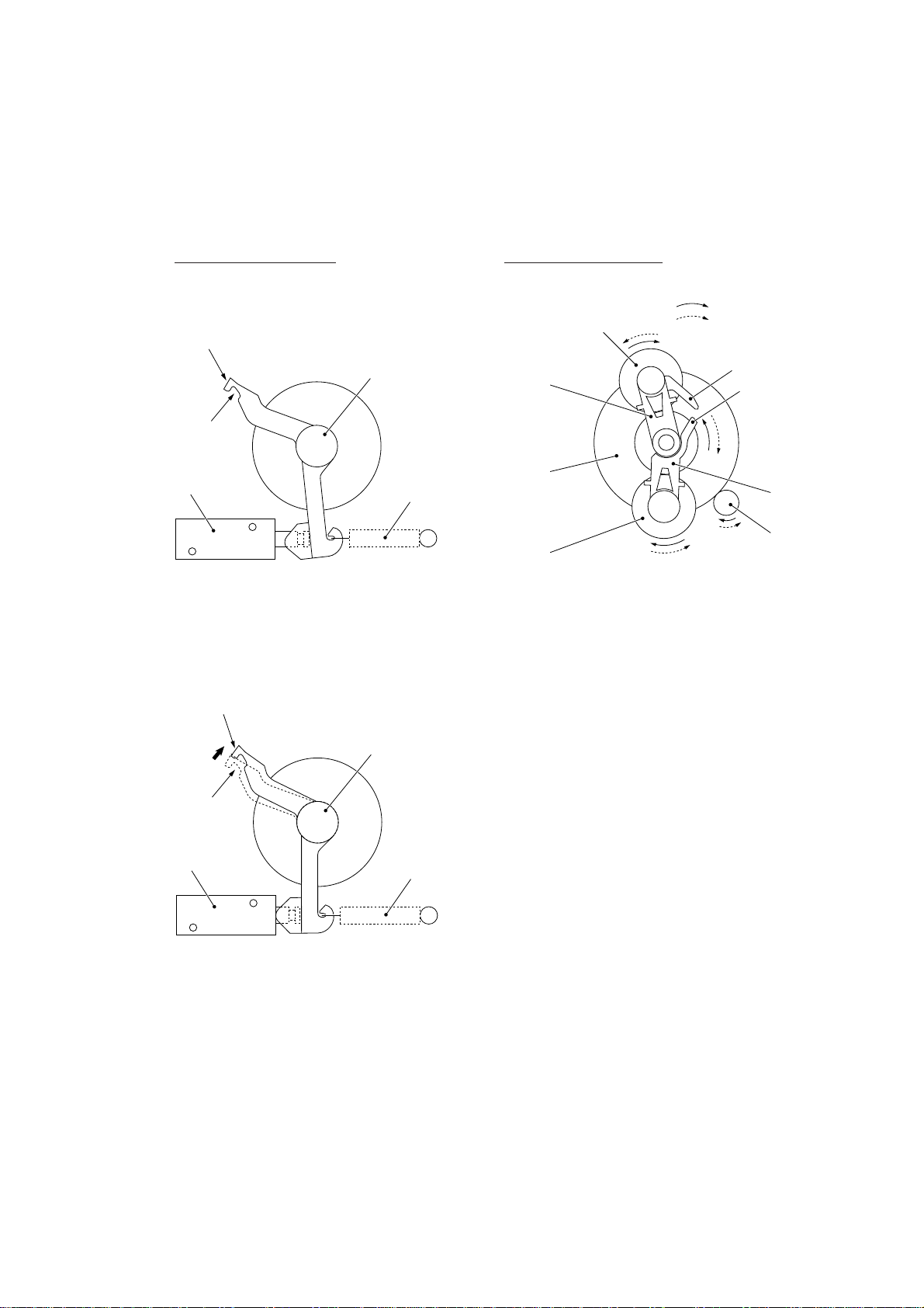
This section describes the planetary gear system of the sun gear 20/90 ("B"). It consists of
the sun gear 20/90, two planet gears 20, arm A, and arm B, as shown below.
Planet gear 20B
Arm B
Sun gear 20/90
Planet gear 20A
Arm A
Motor gear
Planetary Gear System
If the motor rotates, the sun gear 20/90 rotates so that the rotational torque is transmitted to
the engagement between the sun gear and the planet gears 20. Since the arms and planet
gears are so designed that the moment of the arms is less than that of the planet gears, the
arms turn around the center shaft in the same direction as the sun gear 20/90.
If the planet gear(s) becomes engaged with any other gear so that the arm cannot turn furthermore, the rotational torque of the sun gear 20/90 is transmitted to that planet gear. Accordingly, the planet gear starts rotation in the opposite direction of the sun gear 20/90.
III – 6
Page 19
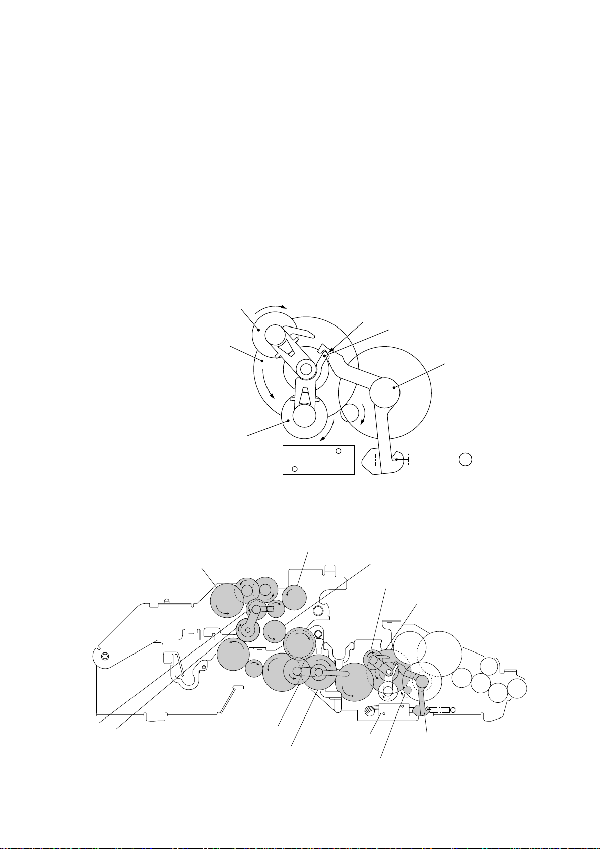
2.3.3 Power transmission for four operation modes
Depending upon the solenoid ON/OFF state and the motor rotation direction, the planetary
gear train switches the power transmission route for the four operation modes.
Solenoid ON/OFF state Motor rotation direction
Solenoid: OFF
Section y (to block the
stoppper of arm B)
Cutout x (engaged
with the stopper of
arm A)
Solenoid
Solenoid: ON
Section y (to block the
stoppper of arm B)
Clutch lever
Spring
Planet gear 20B
Arm B
Sun gear
20/90
Planet gear
20A
Forward
Reverse
Stopper of
arm B
Stopper
of arm A
Arm A
Motor
gear
Cutout x (engaged
with the stopper of
arm A)
Solenoid
Clutch lever
Spring
III – 7
Page 20
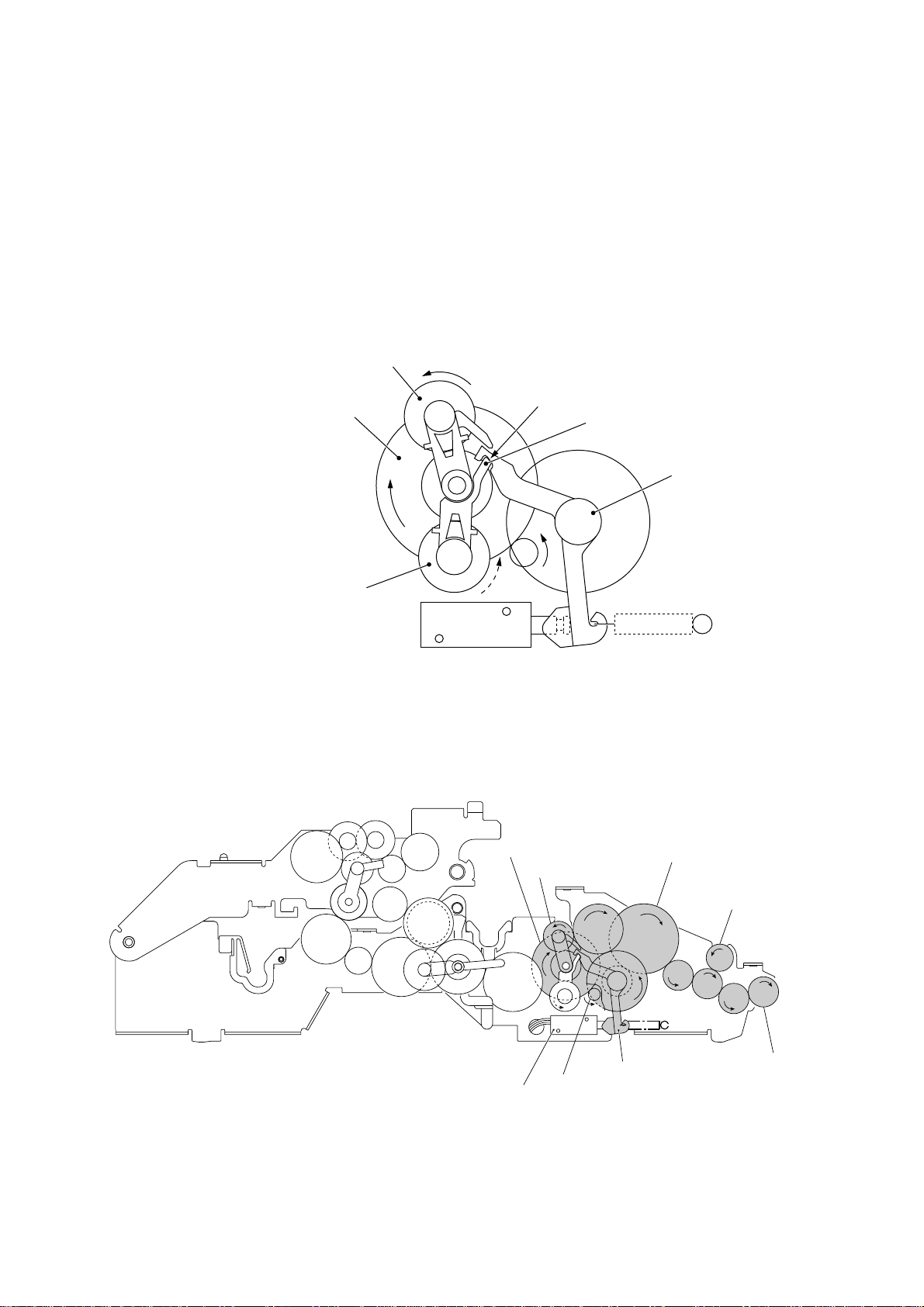
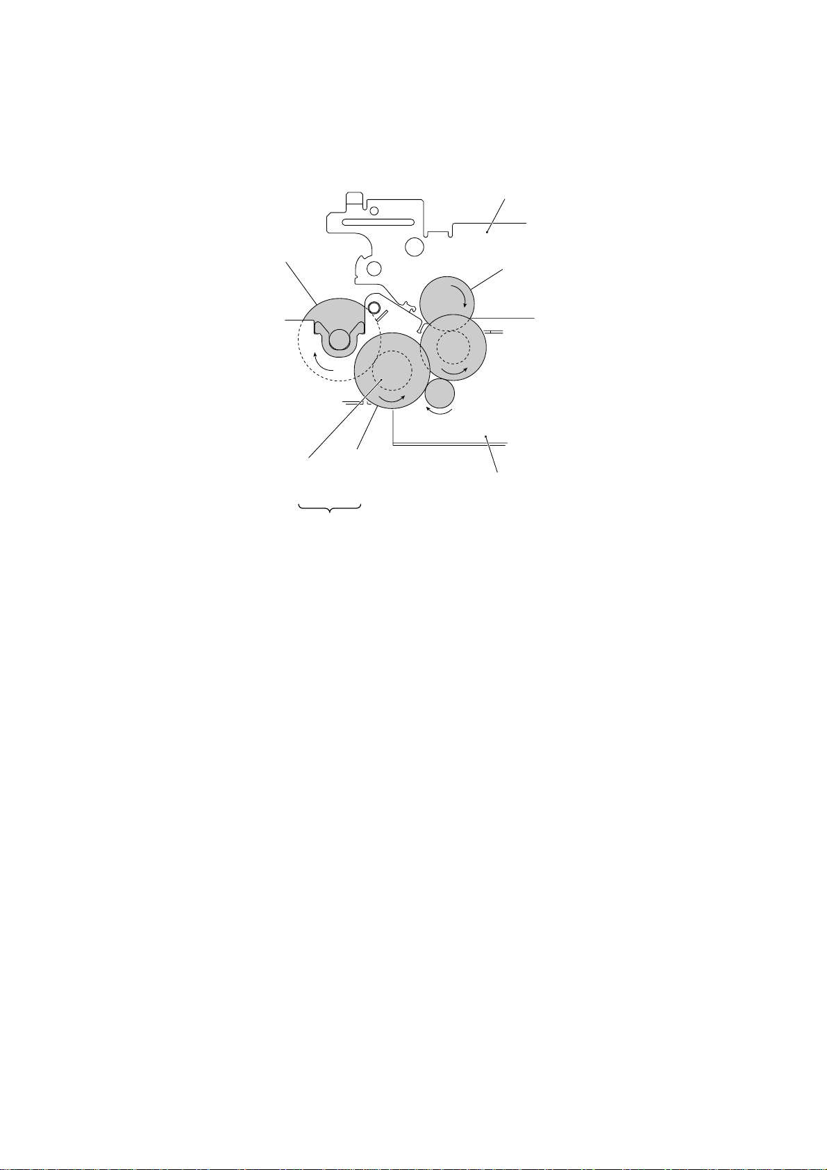
[ 1 ] Scanning mode (Solenoid: OFF, Motor rotation: Reverse)
In the scanning mode, the control electronics deactivates the solenoid. When the motor rotates in the reverse direction, the clutch lever turns counterclockwise with the spring so that
its cutout x becomes engaged with the stopper of arm A. Once arm A is locked, the planet
gear 20A ("L") will not be engaged with any other gear but simply idle.
The motor's rotational torque turns the sun gear 20/90 ("B") clockwise so that the planet gear
20B ("C") transmits the torque to the separation roller gear ("F"), white pressure roller gear
("I") and document ejection roller gear ("K") via the several gears.
C (Planet gear 20B)
B (Sun gear 20/90)
L (Planet gear 20A)
Arm A Locked by Cutout
Solenoid
xx
x of Clutch Lever
xx
B (Sun gear 20/90)
Cutout x of clutch lever
Stopper of arm A
Clutch lever
F (Separation
roller gear)
C (Planet gear 20B)
I (White pressure
roller gear)
Solenoid
Active Gears
III – 8
D
L
Clutch lever
A (Motor gear)
G
H
E
J
K (Document
ejection roller
gear)
(Front)
Page 21
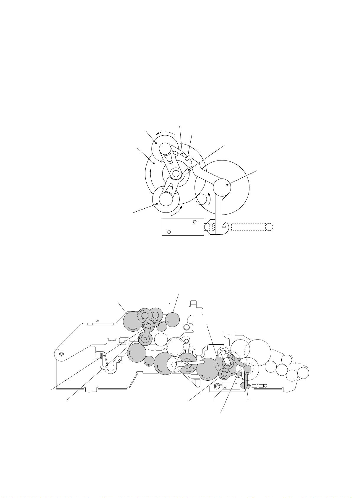
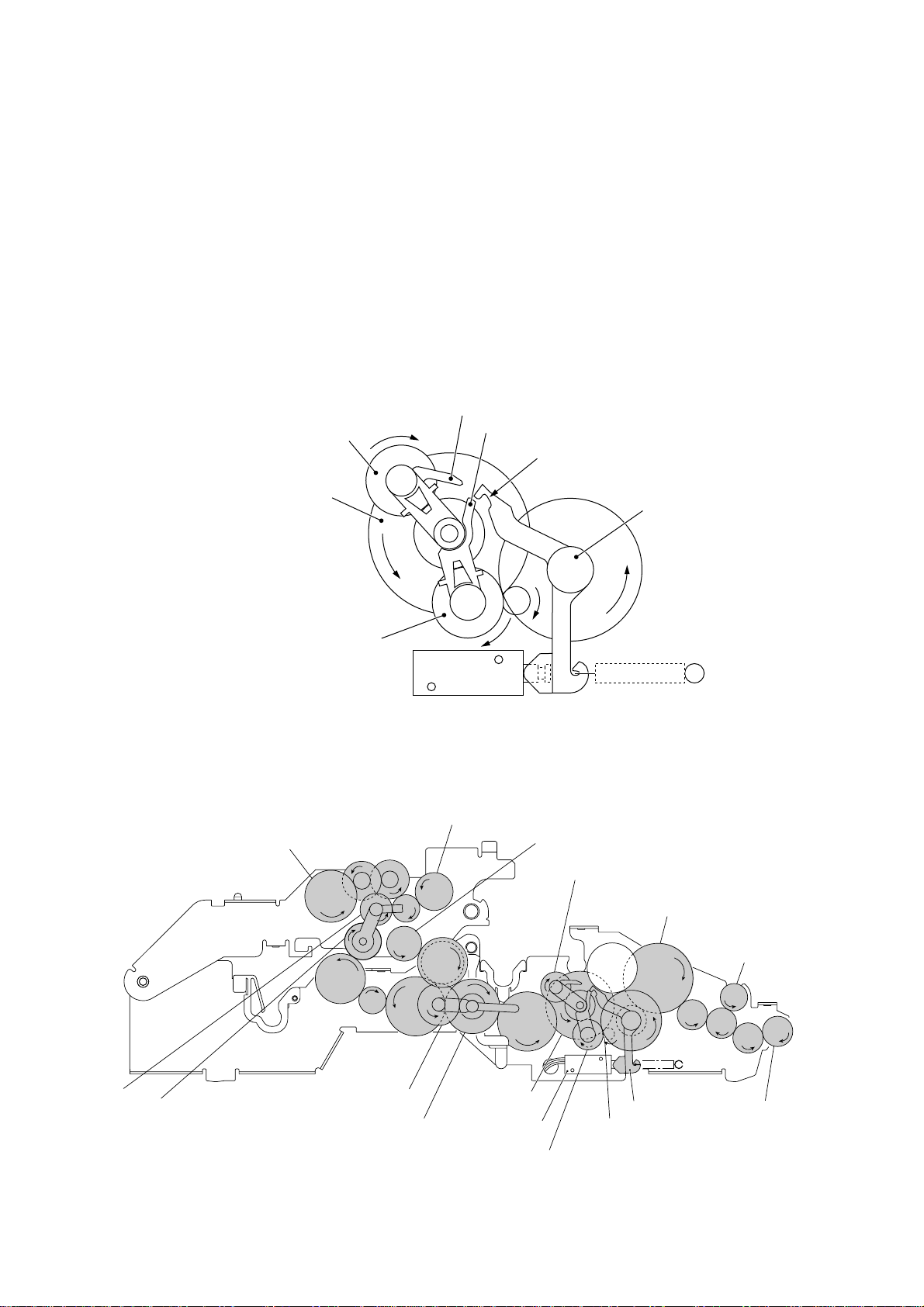
[ 2 ] Paper feeding/ejecting mode (Solenoid: ON, Motor rotation: Reverse)
In the paper feeding/ejecting mode, the control electronics activates the solenoid to release
the stopper of arm A. When the motor rotates in the reverse direction, the sun gear 20/90
("B") rotates clockwise so that the planet gear 20A ("L") transmits the torque via the gear 39
("M") and other gears to the paper feed roller gear ("T") and paper ejection roller gear ("X").
Since the stopper of arm B is blocked by the section y of the clutch lever, the planet gear
20B ("C") is merely idle without engaging with any other gear.
Stopper of arm B
C (Planet gear 20B)
Section y of clutch lever
B (Sun gear 20/90)
L (Planet gear 20A)
T (Paper feed roller gear)
Stopper of arm A
Solenoid
Arm B Blocked by Section y of Clutch Lever
X (Paper ejection roller gear)
V
U
B (Sun gear 20/90)
W
Clutch lever
S (Planet
gear 34)
R (Sun gear 39/24)
Q
P
O
L (Planet gear 20A)
Active Gears
III – 9
C
N
Y
M
(Front)
Solenoid
Clutch lever
A (Motor gear)
Page 22
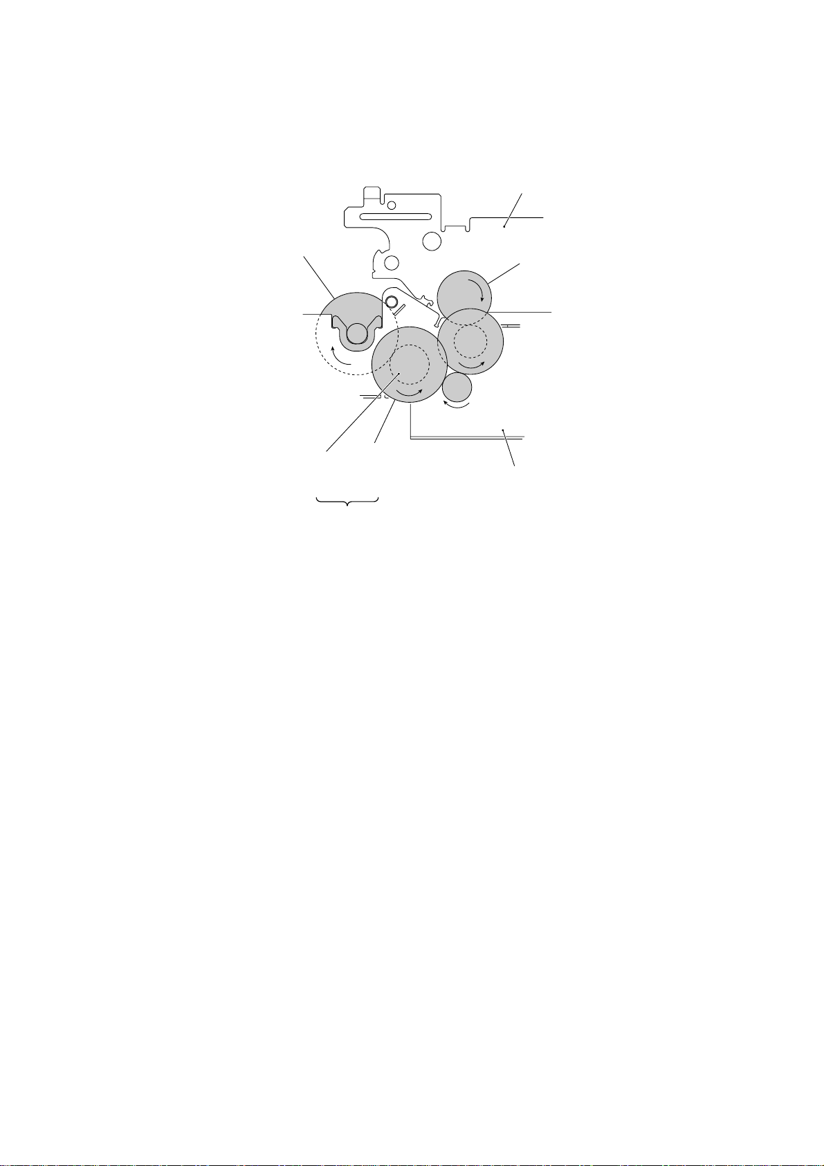
[ 3 ] Recording mode (Solenoid: OFF, Motor rotation: Forward)
In the recording mode, the control electronics deactivates the solenoid. When the motor rotates in the forward direction, the clutch lever turns counterclockwise with the spring so that
its cutout x becomes engaged with the stopper of arm A. Once arm A is locked, the planet
gear 20A ("L") will not be engaged with any other gear but simply idle.
The motor's rotational torque turns the sun gear 20/90 ("B") counterclockwise so that the
planet gear 20B ("C") transmits the torque via the gear 39 ("M") and other gears to the platen
gear ("a") as well as the paper ejection roller gear ("X").
The platen advances recording paper and its paper movement rotates the paper feed roller.
Consequently, the paper feed roller shaft rotates faster than the paper feed roller gear ("T").
If the platen gear ("a" in the figure below) on the left end of the platen shaft rotates, the gear
33RB ("b") on the right end also rotates so as to drive the friction torque transmission ASSY
and ribbon drive gear ("e") that rotates the ribbon take-up gear ("f") in the ribbon cartridge, as
shown on the next page.
C (Planet gear 20B)
B (Sun gear 20/90)
L (Planet gear 20A)
T (Paper feed roller gear)
Solenoid
Arm A Locked by Cutout
X (Paper ejection roller gear)
V
U
Cutout x of clutch lever
xx
x of Clutch Lever
xx
a (Platen gear)
C (Planet gear 20B)
Stopper of arm A
Clutch lever
S (Planet
gear 34)
R (Sun gear 39/24)
W
Z
Q
P
Y (Planet gear 44)
N (Sun gear 36/27)
Active Gears on the Left Side
O
III – 10
B (Sun gear 20/90)
M
L
(Front)
Clutch leverSolenoid
A (Motor gear)
Page 23
f (Ribbon take-up gear
in the ribbon cartridge)
Platen frame
b (Gear 33RB)
(Front)
Ribbon
drive gear
(Gear 24)
c
d
Friction torque
transmission
ASSY (Gear 46)
e
Active Gears on the Right Side
Main frame
III – 11
Page 24
[ 4 ] Copying mode (Solenoid: ON, Motor rotation: Forward)
The control electronics activates the solenoid to release the stopper of arm A from the clutch
lever. When the motor rotates in the forward direction, the sun gear 20/90 ("B") rotates
counterclockwise so that the planet gear 20A ("L") transmits the torque to the document
scanner mechanism (e.g., the separation roller gear ("F"), white pressure roller gear ("I") and
document ejection roller gear ("K")) and the planet gear 20B ("C") transmits the torque to the
recording mechanism (e.g., the platen gear ("a"), paper feed roller gear ("T"), and paper
ejection roller gear ("X")).
If the platen gear ("a" in the figure below) on the left end of the platen shaft rotates, the gear
33RB ("b") on the right end also rotates so as to drive the friction torque transmission ASSY
and ribbon drive gear ("e") that rotates the ribbon take-up gear ("f") in the ribbon cartridge, as
shown on the next page.
Stopper of arm B
C (Planet gear 20B)
Stopper of arm A
Cutout x of clutch lever
B (Sun gear 20/90)
L (Planet gear 20A)
T (Paper feed roller gear)
Solenoid
Arm A Released from Coutout
X (Paper ejection roller gear)
U
V
W
a
Z
XX
X of Clutch Lever
XX
a (Platen gear)
C (Planet gear 20B)
Clutch lever
F (Separation roller gear)
I (White pressure
roller gear)
S (Planet
gear 34)
R (Sun gear 39/24)
Q
P
Y (Planet gear 44)
N (Sun gear 36/27)
Active Gears on the Left Side
O
B (Sun gear
20/90)
III – 12
M
Solenoid
L
E
Clutch lever
A (Motor gear)
L (Planet gear 20A)
G
H
J
(Front)
K (Document
ejection roller
gear)
Page 25
f (Ribbon take-up gear
in the ribbon cartridge)
Platen frame
b (Gear 33RB)
(Front)
Ribbon
drive gear
(Gear 24)
Friction torque
transmission
ASSY (Gear 46)
e
Active Gears on the Right Side
c
d
Main frame
III – 13
Page 26
2.3.4 Power transmission route
Rotation of the motor gear is transmitted as shown below.
U
V
T
S
R
Q
P
X
W
a
Z
O
Y
Gears on the Left Side
f
D
C
N
b
c
B
M
L
A
F
I
G
H
E
K
J
e
d
Gears on the Right Side
A: Motor gear
B: Sun gear 20/90
C: Planet gear 20B
D: Gear 33
E: Gear 20/40
F: Separation roller gear
G: Gear 14/20
H: Gear 14/20
I: White pressure roller gear
J: Gear 14/20
K: Document ejection roller gear
L: Planet gear 20A
M: Gear 39
N: Sun gear 36/27
O: Gear 39
P: Gear 18
Q: Gear 33
R: Sun gear 39/24
S: Planet gear 34
T: Paper feed roller gear
U: Gear 18/41
V: Gear 18/41
W: Clutch gear
X: Paper ejection roller gear, Gear 40
Y: Planet gear 44
Z: Gear 33/45
a: Platen gear, Gear 23
b: Gear 33RB
c: Gear 20/40
d: Gear 18
e: Friction torque transmission ASSY (Gear 46)
and ribbon drive gear (Gear 24)
f: Ribbon take-up gear in the ribbon cartridge
[ 1 ] Scanning Mode (Solenoid: OFF, Motor rotation: reverse)
A ➜ BC ➜ D ➜ E ➜ F ➜ G ➜ H
(Motor)
L (Idling)
(Separation
roller)
I (White pressure roller)
J ➜ K
(Document
ejection roller)
[ 2 ] Paper Feeding/Ejecting Mode (Solenoid: ON, Motor rotation: reverse)
C (Idling)
A ➜ BL ➜ M ➜ NO ➜ P ➜ Q ➜ R ➜ S ➜ T ➜ U ➜ V ➜ W ➜ X
(Motor)
Y (Idling)
(Paper feed
roller)
III – 14
(Paper ejection
roller)
Page 27

[ 3 ] Recording Mode (Solenoid: OFF, Motor rotation: forward)
A ➜ BC ➜ M ➜ N
(Motor)
L (Idling)
Y ➜ Z ➜ a (Platen) ➜ b ➜ c ➜ d ➜ e ➜ f (Ribbon take-up gear)
O ➜ P ➜ Q ➜ R ➜ S ➜ WX (Paper ejection roller)
[ 4 ] Copying Mode (Solenoid: ON, Motor rotation: forward)
Y ➜ Z ➜ a (Platen) ➜ b ➜ c ➜ d ➜ e ➜ f (Ribbon take-up gear)
A ➜ B
(Motor)
C ➜ M ➜ N
L ➜ E ➜ F➜ G ➜ HI (White pressure roller) V ➜ U ➜ T
(Separation
roller)
O ➜ P ➜ Q ➜ R ➜ S ➜ WX (Paper ejection roller)
J ➜ K
(Document
ejection roller)
V ➜ U ➜ T
(Paper feed
roller, Idling)
(Paper feed
roller)
III – 15
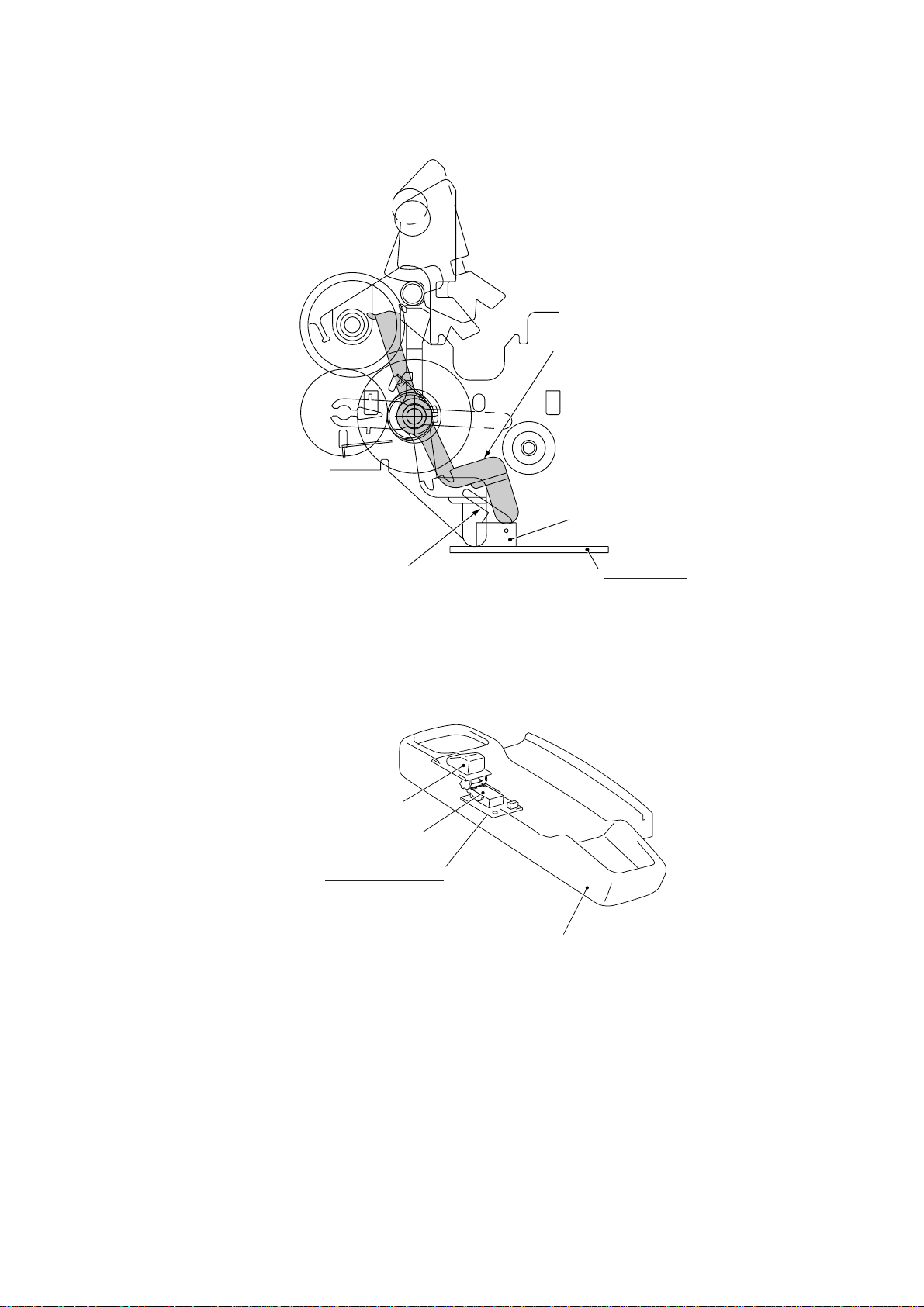
Page 28

2.4 Sensors and Actuators
This equipment has four photosensors and three mechanical switches (two for the FAX1010)
as described below.
Sensor name Type Located on
Document front sensor Photosensor (PH1) Main PCB
Document rear sensor Photosensor (PH2) Main PCB
Paper ejection sensor Photosensor (PH1) Sensor PCB
Paper-edge sensor Photosensor (PH2) Sensor PCB
Cover sensor Mechanical switch (SW1) Modular PCB
Ribbon sensor Mechanical switch (SW1) Recording head
Hook switch sensor* Mechanical switch (SW1) Hook switch PCB
• Document front sensor which detects the presence of documents.
• Document rear sensor which detects the leading and trailing edges of pages to tell the
control circuitry when the leading edge of a new page has reached the starting position
and when the scan for that page is over.
• Paper ejection sensor which detects whether a paper jam has occurred.
• Paper-edge sensor which detects the leading and trailing edges of paper and the presence of paper as well as detecting whether the paper front cover is closed.
These photosensors are of a reflection type consisting of a light-emitting diode and a lightsensitive transistor. Each of them has an actuator separately arranged (see the next page),
except that the paper-edge sensor has two actuators for sensing the paper and the paper
front cover. When an actuator is not activated, its white end lies in the path of light issued
from the light-emitting diode and reflects its light so that the reflected light enters the lightsensitive transistor. If a document or paper comes in so as to activate the actuator, the
actuator's white end goes out of the light path and no reflected light enters the light-sensitive
transistor. This way, the sensor detects the presence of documents or paper.
• Cover sensor which detects whether the recording paper cover ASSY is closed.
• Ribbon sensor which detects whether the ink ribbon is loaded.
• Hook switch sensor* which detects whether the handset is placed on the handset mount.
The cover sensor has an actuator separately arranged (see page III-18). If the actuator is
activated, its lower end releases the cover sensor lever so that the sensor signals the detection.
Path of actuator's end
Approx. 0.7 mm
* Not provided on the FAX1010
Lightemitting
diode
Lightsensitive
transistor
Glass
III – 16
Page 29
(Front)
Main PCB
Front cover
sensing actuator
Document rear sensor
Document rear sensor actuator
Document front sensor
Document front sensor actuator
Paper-edge sensor actuator
Paper-edge sensor
Paper ejection sensor
actuator
Paper ejection sensor
(Front)
Recording head
Ribbon sensor
Ribbon sensor actuator
Location of Sensors and Actuators (1)
III – 17
Sensor PCB
Page 30
Cover sensor actuator
Cover sensor
Cover sensor lever
Hook switch sensor actuator**
Hook switch sensor**
Hook switch PCB**
Modular PCB
Handset mount*
Location of Sensors and Actuators (2)
* Not provided on the FAX1010
** Not provided on the FAX1010 or those versions equipped with a Binatone handset
III – 18
Page 31

3. CONTROL ELECTRONICS
3.1 Configuration
The hardware configuration of the facsimile equipment is shown below.
Line
External
telephone
Handset*
2-pin
4-pin
2-pin
NCU PCB
(Note)
(Note)
12-pin: U.S.A. versions
18-pin: European versions
Speaker
PC I/F
Motor
Modular
PCB
Solenoid
Recording head
2
*
8-pin
2-pin
6-pin
2-pin
11-pin
5-pin
Sensor
PCB
*
P2
ASIC
Main PCB
1
*
14-pin
Control
panel PCB
5-pin
7-pin
CIS unit
COG
14-pin
FPC key
2-pin
2-pin 4-pin 2-pin
*
3
Hook
*
switch
PCB
5
4-pin
4
*
Microphone
(Only on the FAX1570MC/1030/MFC1870MC/1970MC)
Power supply PCB
Ni-MH
battery
* Not provided on
the FAX1010
1
*
On the main PCB are these sensors:
• Document front sensor (PH1)
• Document rear sensor (PH2)
2
*
On the modular PCB is the cover sensor.
3
*
On the sensor PCB are these sensors:
• Paper ejection sensor (PH1)
• Paper-edge sensor (PH2)
4
*
On the hook switch PCB* is the hook switch sensor (SW1).
5
*
On the recording head is the ribbon sensor (SW1).
Configuration of Facsimile Equipment
III – 19
Page 32

3.2 Main PCB
The main PCB, which is the nucleus controlling the entire operation of the equipment, consists of a FAX engine (ASIC), memories, MODEM, motor drive circuitry, sensor detection circuitry, and analog circuits for scanning, recording, and power transmission shifting.
NCU
Power
supply
ROM
E2PROM
DRAM
FAX
engine
(ASIC)
Motor
driver
Control panel
Recording head
CIS
Motor
Speaker
Modular
PCB (for
PC I/F)
Hook
switch
sensor*
Sensors
** Not provided on the
FAX1010 or those
versions equipped
with a Binatone
handset
On the following pages, the main PCB circuit diagrams are described on the basis of the
FAX1570MC/1030/MFC1870MC/1970MC.
Sensors
2
E
PROM: Electrically Erasable Programmable Read-only Memory
DRAM: Dynamic Random Access Memory
Block Diagram of Main PCB
Ni-MH battery
Microphone
III – 20
Page 33

12345678
L3 0
6
PANEL
P11
B5B-PH
WHI T E
GND FG
+5V
R8
*
5
1
3
2
4
GND
33A LI GT
42F DASNO
43D DAREC
42F DAST
E5V
E0V
E5V
R92
75F
R93
100F
R94
75F
E0V
C16
CC104
R96
75K
R95
10KF
C78
CC104
GND
7
+26V
E0V
C79
CC104
C14
C101
C50
0
C77
CC104
R7 4 70
15B PCLK
15B SDOT
R9 470
15B SDIN
C15
C13
C101
C101
+5V
#9
T7D60
R132
10K
R87 10K
17
ADPDMD
52C CLBSY
52D CLRXS
R133 10 k
32F RIBON
42F TLOF2
43B TADH
44D TXSL
45D HAFH
46E SPON
38C FRNT
37B FSEN
37B RSEN
17B CSEN
38C REAR
32E ST1
32E ST2
32E HDC
32E DIN
32E DOUT
34C E1CS
34C SMC
36C RDAT
23C MTI1
23C MTI0
32A RB
37D SEON
33B VI D
C39
CC104
MI O0 ( P WM)
18
MI O1 ( P WM)
19
MI O2 ( P WM)
20
MI O3
21
MI O4
22
MI O5
23
MI O1 1
24
MI O1 2
25
MI O1 3
205
MVDD
208
MVSS
204
MONMDCK
103
LIGT(PWM)
80
SEON(OD)
76
SEN2
77
SEN3
78
SEN4
79
SEN5
30
SEN6
31
SEN7
32
SEN8
92
ST1
91
ST2
93
HDC
94
DI N
90
DOUT
106
E1CS
107
SPSL( SMC)
102
RDAT
95
CL2
98
CL1
99
CLB
100
RB
101
DI F
104
TG
52
RDA61
56
CP1I
55
CP3I
54
CP4I
53
CPNN
50
RDA6
51
AVDD
58
AVDD
49
REFH
48
REFL
47
AGND VSS
59
AGND
AAPDMD
DPDMDT
DPDMCK
APDMCK
APDMDT
AMUTE
MEXTL
MUTE
MTXL
DA0
DA1
DA2
DA3
DA4
DA5
DA6
DA7
DA8
DA9
D00
D01
D02
D03
D04
D05
D06
D07
VDD
VDD
VDD
VDD
VDD
VDD
VDD
VDD
VDD
VSS
VSS
VSS
VSS
VSS
VSS
VSS
VSS
VSS
VSS
R59 10k
R68 10k
L5V
C70
C38
CC104
0
+5V
GND
GND
R86 *
C68
*
GND
34C,32A TG
33D CP3I
E5V
C73
C76
CC104
CC104
E0V
A
B
C
D
+5V
GND
E
F
+5V
5
Q6
RH5VA4 3
VCC
OUT
GND
GND
R70
200
16
ADMD
14
AAMD
R67
200
12
DMT
R66
300
11
DMK
R64
300
9
AMK
8
AMT
3
C5
C4
C3
C2
C1
C0
C3
2
C4
1
C5
6
C0
5
C1
4
C2
13
AMUT
7
MUT
207
L2 100
206
R117 20 0
109
DA0
R118
110
DA1
200
111
DA2
RA2
112
DA3
200
113
DA4
115
DA5
116
DA6
RA1
117
DA7
200
118
DA8
120
DA9
127
D0
128
D1
129
D2
130
D3
131
D4
133
D5
134
D6
135
D7
10
43
97
114
132
147
165
190
201
15
38
60
81
96
C43
C51
105
CC104
CC104
119
142
156
164
200
R90
1.5K
C65
CC104
C61
CC30P
TBUS 48A,58D
DABUS
26B,26E
DBUS 25E,36D
C59
CC104
RSTL 16A,47B, 14B,57E
R80 1M
XT1
CSA16 MX
GND
14A RSTL
#12 74VHCU04FS
R60 4.7K
R61
XT2
220
D57. 6 D6
C42
CC5P
C0V
C60
c63
CC104
CC104
2
1432
C71
CC102B
C66
CC104
#9
T7D60
44
143
141
R116 10 0
27B RMRD
27B ROMC
12B PCLK
+5B
12B SDOUT
12B SDIN
R88 100
14A RSTL
25C BARMRD
25C BARMWE
42F ADLC
46E VOL1
42F EAT
42B,38E CMLH
42E RDPS
43E PLS
43A TELL
17C HOOK
42F CI
42F TLOF
45E RNGO
46E VOL3
46D RNGL
42D OTO
32F LATC
33C CLMP
33C CPWM
53B CLSEL
25B EPCK
23F SOL RM3
38E PWON
34C SRAM
25B EPDO
23E MTVR
R131 10 K
L5V
+5V
L4
0
C72
CC104
GND
R114100
R79 *
R78 *
L5V
GND
L5V
P7 *
SHORT-2
GND
C0V
70
75
124
123
122
166
167
177
176
175
67
66
68
73
74
65
72
71
57
83
82
187
188
189
191
192
193
194
195
39
40
184
203
89
185
186
26
27
28
29
182
183
108
41
121
69
88
74VHCU0 4F S
5137
25D RAS
R82
0
25D CAS
C62
CC30P
R84
22K
R85 *
+5B
C67
CC104
GND
GND
8
4
C41
CC5P
GND
C69
CC104
RST
EXTL
XTL
RAS0
CAS
RMRD
RMWE
ROMC
IORD
IOWE
PCLK
SDOUT
SDIN
CK32ON
CK32
BAKCLK
BAENB
BAVDD
BAKSEL
BARMRD
BARMWE
LNCR(COMP)
SOL ( OD)
PWON
CML
DPS
PLS
TEL
HOOK
CI
TLOF
STD
RI NG
SPON
E2CS
CTXD
PO1
PO2
P03 ( OD)
RM1
RM2
RM4
PIO1
PIO2
PIO3( SRAM)
PIO4( OD)
PIO5
PIO6
EIT 1
#12
119
1
64
RSTL 14A
RTCCON
61
RVDD
RVDD
62
REXT
63
RXT
202
CRXD
199
CKS
196
TXD
197
RXD
198
CTS
84
MM1
85
MM2
86
MM3
87
MM4
45
TSTA
46
TSTB
125
IORQ
126
MREQ
140
CK16
144
CK8M
145
RD
146
WR
168
NMI
169
INT
170
BSAK
171
BSRQ
172
WAI T
173
RFSH
174
M1
136
A0
137
A1
138
A2
139
A3
148
A4
149
A5
150
A6
151
A7
152
A8
153
A9
154
A10
155
A11
157
A12
158
A13
159
A14
160
A15
161
MA1 6
162
MA1 7
163
MA1 8
178
ODPI O0
179
ODPI O1
180
ODPI O2
181
ODPI O3
42
VOL2 46E
ODPI O4
33
FDCLK
34
FDOUT
35
FDIN
36
CTSEL 53A,53B
FCS1
37
FCS2
+5V
L1
0
14
C40
CC104
LX
0
GND
R81 200
GND
CLRST
CLTXS
R91
0
CRXD
CKS
TXD
RXD
CTS
PBUS
17B
MM1
MM2
MM3
MM4
MBUS 23C
L5V
IORQ
R83 10K
MREQ
CK16
RD
WR
RBUS 3 4D
A0
A1
A2
A3
A4
A5
A6
A7
A8
A9
A10
A11
ABUS 26B,34D
CLCI
CLCK
CLBUS 51C
3
XT3
C-001R
C75
C74
CC10P
CC12P
GND
16B PBUS
L5V
R10
4.7K
12D CSEN
GND
R11
4.7K
15C HOOK
GND
+5B
+5V
D1
R125
*
0
A
RVDD
R127
C108
*
CC104
GND
C6
*
GND
PCI
+5V
CRXD
CKS
+5V
TXD
RXD
CTS
C17
*
GND
P15
IMSA-9110S-08L
+5V
HOOK
L5
MMZY601B
C18
CC101
GND
P14
B2B- PH
WHI T E
A
3
B
1
6
5
9
4
2
8
7
C
1
:
2
D
E
F
21 345678
Main PCB Circuit Diagram 1/5
1 FAX engine (ASIC) which integrates a CPU, digital portion of MODEM and gate array
for managing the I/Os, memories, and drivers.
2 XT1, oscillator for the CPU.
3 XT3, oscillator for the calendar clock.
4 XT2, oscillator for the MODEM.
5 Reset IC which turns on at the powering-on sequence and at any of the reset opera-
tions.
6 Connector for the control panel
7 Recording head drive voltage detector
8 Inverters
9 Connector for the modular PCB
: Connector for the hook switch PCB
A Backup circuit for the calendar clock
III – 21
Page 34

12345678
PS
+26V
4
1
1
A
2
3
P0V
P3
B4B-PH
+9V
DA1
1SS378
3
5
7
BAT
1
2
GND
P6
B2B-PH
BLACK
MOTOR
3
4
2
6
5
1
P2
B6B-PH
+5V
R130
R110
20K
0
C106
P0V
SOL
P13
B2B-PH
BLUE
CC332B
R111
*
R2
1/2W
1
Q11 *
+26V
1
D3
1SS120
2
R112
*
B
C
D
E
F
+9V
C3
C96
16V47
CC104
GND
R113
1K
C91
CC104
R1
1/2W
1
P0V
Q2
DTD113 ZK
GND
2
#3 KIA7805
IN OUT
GND
C97
C5
CC104
16V47
+5V
4
Q12 RH5RA47
IN OUT
2
7
817
13
3
5
6
9
10
12
19
24
22
21
23
4
20
11
GND
#1
MTD2003F
OUT1
OUT2
OUT3I0IN3
OUT4
NC
NC
NC
NC
NC
NC
NC
6
NC
VR
C/ R
VSA
RSA
VSB
RSB
R119
*
C4
16V47
GND
27
MM1
IN1
26
MM3
IN2
MM2
16
MM4
IN4
25
18
I1
1
VMM
14
VMM
15
VCC
28
VCC
29
GND
30
GND
MTVR 15D
SOL 1 5D
+5V
15D EPCK
15D EPDO
+5B
MBUS 16B
15A RAS
MTI 0 12 E
MTI 1 12 E
+26V
+5V
C105
C90
CC104
CC104
C1
C107
35V/220
50v
105 C
CC104
P0V
15A CAS
15B BARMWE
15B BARMRD
14D DABUS
14E DBAS
C95
CC104
R120
4.7k
8
VCC VSS
6
SCL
A0
5
SDA
A1
7
TEST A2
#4
24LC16(1870MC)
24LC32(1970MC)
C94
CC104
#7 (1970MC)
HM514400
13
VCC26VSS
4
-RAS
23
-CAS
3
-WE
22
-OE
9
DA0
DQ1
A0
10
DA1
DQ2
A1
11
DA2
DQ3
A2
12
DA3
DQ4
A3
14
DA4
A4
15
DA5
A5
16
DA6
A6
17
DA7
A7
18
DA8
A8
5
DA9
A9
8
GND+5V
R76 STD MODEL=0
D. S MODEL= *
R77 STD MODEL=*
D. S MODEL=0
14D DABUS
16D ABUS
+5V
15A ROMC
15A RMRD
A0
A1
DA9
A2
A3
A4
A5
A6
A7
A8
A9
A10
A11
DA3
DA4
DA5
DA6
DA7
DA8
4
1
2
3
#8
PD27C2001B-15
1
VPP
32
VCC
22
-CE
24
-OE
31
-PGM
12
A0
11
A1
10
A2
9
A3
8
A4
7
A5
6
A6
5
A7
27
A8
26
A9
23
A10
25
A11
4
A12
28
A13
29
A14
3
A15
2
A16
30
A17 D7
C58
CC104
9
GND+5V
16
GND
13
D0
D0
14
D1
D1
15
D2
D2
17
D3
D3
18
D4
D4
19
D5
D5
20
D6
D6
21
D7
A
B
C
GND+5B
D0
1
DA0
D1
2
DA1
D2
24
DA2
D3
25
DA3
DA4
DA5
DA6
DA7
DA8
DA9
C93
CC104
#5 (1970MC)
HM514400
13
VCC26VSS
4
-RAS
23
-CAS
3
-WE
22
-OE
9
A0
10
A1
11
A2
12
A3
14
A4
15
A5
16
A6
17
A7
18
A8
5
A9
GND+5B
D4
1
DA0
DQ1
D5
2
DA1
DQ2
D6
24
DA2
DQ3
D7
25
DA3
DQ4
DA4
DA5
DA6
DA7
DA8
DA9
C64
CC104
#6 (1870MC)
HM514800JP
1
VCC15VSS
14
VCC
8
-RAS
23
-CAS
7
-WE
22
-OE
10
A0
11
A1
12
A2
13
A3
16
A4
17
A5
18
A6
19
A7
20
A8
9
A9
A
GND+5B
28
VSS
6
NC
21
NC
D0
2
DQ1
D1
3
DQ2
D2
4
DQ3
D3
5
DQ4
D4
24
DQ5
D5
25
DQ6
D6
26
DQ7
D7
27
DQ8
D
E
:
F
21 345678
Main PCB Circuit Diagram 2/5
1 Connector for the power supply PCB which supplies 25V and 8V.
2 3-terminal regulator which eliminates unstabilized components of the +8V source to
generate stabilized +5V source.
3 Connector for the Ni-MH battery which supplies approx. 5V.
(Provided on the FAX1570MC/1030/MFC1870MC/1970MC)
4 3-terminal regulator which generates +5B source from +8V to back up the DRAM
(that stores received data).
(Provided on the FAX1570MC/1030/MFC1870MC/1970MC)
5 Connector for the motor
6 Motor driver
7 Connector for the clutch solenoid (that switches the power transmission).
8 E2PROM (32-kilobit for the FAX1570MC/1030/MFC1970MC, 16-kilobit for other mod-
els.)
9 ROM (2-megabit. Note that the qualification machines for demonstration have a 4-
megabit ROM.)
: DRAMs (1-megabyte, two 4-megabit chips) provided on the FAX1570MC/1030/
MFC1970MC.
A DRAM (512-kilobyte) provided on the MFC1870MC. The FAX1170/1270/1010/1020/
MFC1770 has its equivalent DRAM on location #7.
III – 22
Page 35

1
1
1
2
2
2
2
2
2
12345678
+5V
#10
LC82102W
42
RSTH VDD
38
RSTL
39
AIN
40
TEMP
41
ATAP
37
ADREFL
45
PORT0
44
PORT1
35
PORT2
34
PORT3
43
AVDD
36
AGND
46
AGND
31
TRIG
30
ICLK
29
IOCS
28
MCS
27
IOE
23
ME
22
RD
21
WR
25
CLKI N
32
RESET
20
A0
19
A1
18
A2
16
A3
15
A4
14
A5
13
A6
12
A7
11
A8
SD/PD7
R5V
12D FSEN
12D RSEN
4
4
-1
-2
R129
100K
Q13
KRC107S
+5V
R128
100K
C112
*
C103
C104
CC102B
CC102 B
GND
+5V
R126
PH2
100K
SG-105F308
GND
+5V
R124
PH1
100K
SG-105F308
GND
GND
6
1
4
3
2
#13
UMG5N
GND
-2
1
+5V
C99
CC104
GND
RDAT 1 2E
DBUS 1 4E
-7
3
3
-1
12E SEON
33F HRLY
42E CMLL
GND
R0V
10
24
VDD
56
VDD
9
DGND
17
DGND
26
DGND
DGND
DGND
PD6
PD5
PD4
PD3
PD2
PD1
PD0
DACK
DREQ
MTP
SAMP
CLK1
CLK2
C98
49
CC104
64
47
48
50
51
52
53
54
55
57
58
59
GND
33
62
RS
63
SH
61
60
8
D0
D0
7
D1
D1
6
D2
D2
5
D3
D3
4
D4
D4
3
D5
D5
2
D6
D6
1
D7
D7
CIS
A
1
2
3
4
5
7
P9
B7B-PH
TM
9
10
11
8
7
2
3
6
1
5
4
P5
B11B-PH
+26V
R97 470
RB 12 E
R98 270
TG 12E
R5V
C82
CC104
R0V6
C8 16V/ 10
Q10
KRC107S
R102
10K
R0V
R0V
+5V
C88
C84
C89
CC101
CC101
CC101
GND
C86
C87
C83
*
*
*
GND
C109
CC102
R101
10K
C85
CC101
R105
10K
Q1
2SD1858
R3
1W
30
Q9
2SK1399
R5V
R0V
+5V
GND
R106 10 0
R104 20 0
R103 1K
R107
33KF
R108
100KF
R109
10KF
GND
Q7
2SC3052
R5V
Q8
2SC3052
LIGT 11C
-4
1
VID 12E
-5
1
CLMP 15D
R5V
R100
2.2K
CPWM 15D
R99 22K
C80
CC104
R0V
CP3I 12F
ST2 12D
DOUT 12 E
DI N 12E
HDC 1 2D
ST1 12D
LATC 15C
HRLY 36E
RI BON 1 2D
1
-6
R5V
R123
300
R122
200
R121
0
C102
C100
CC104
*
R0V
C81
CC104C716v
10
R0V
R5V
C101
CC104
R0V
12E TG
12E SMC
12E E1CS
15D SRAM
IORQ
MREQ
RD
WR
CK16
16B RBUS
14A RSTL
A0
A1
A2
A3
A4
A5
A6
A7
A8
16D ABUS
-1
-2
-3
B
1
C
2
D
-1
-2
-3
E
-4
-3
-5
F
+26V
REAR 12D
FRNT 12D
4
PWON 15 D
CMLH 15B
3
SENSOR
P1
B5B- PH
BLACK
A
5
2
4
1
3
B
C
D
E
F
21 345678
Main PCB Circuit Diagram 3/5
1 Connector for the CIS
1-1: Power for the CIS LED array
1-2: Clock output
1-3: Trigger signal output. One shot of this signal triggers a line of scan.
1-4 LED control signal output circuit which controls the intensity of the CIS LED array.
1-5: Input of video data (VID) to the FAX engine
1-6: Clamp circuitry that gives the bias level to the amplifier of the VID input circuit according to
the CLMP and CPWM signals issued by the CPU (that monitors the current video data
input) for compensating the DC component of video signals for the next scan line.
Working with the FAX engine, this circuitry carries out the standard scanning. (This
circuitry is provided on the FAX1170/1270/1010/1020/MFC1770/1870MC.)
1-7 SANYO LSI that carries out the high-quality scanning. (Provided on the FAX1570MC/1030/
MFC1970MC)
2 Connector for the thermal recording head
2-1: Power 5V for the thermal recording head
2-2: Thermister signals which are normalized by the resistor network and fed to the FAX engine
2-3: Strobe signals
2-4: Data signals
2-5: Ribbon sensor signal
3 Connector for the sensor PCB
3-1: Paper-edge sensor signal
3-2: Paper ejection sensor signal
4 Document front and rear sensor circuitry that is active only while the SEON signal is on.
4-1:PH2, document rear sensor
4-2:PH1, document front sensor
III – 23
Page 36

12345678
R26 75K
4
C25 CC221
R29 56K
6
-
7
5
+
R30
#18
4.7K
I324
AREF
C28
CC105(2125CHIP)
43
C
C9
16V10
R89
3.3K
C45
CC104
R62
100K
R36
1K
Q5 KRC1 07 S
C44
CC221
C48
CC104
AREF
R34
300
M0V
M0V
R63 1K
C46
D2
CC103B
HZS5C
M0V
-3
2
RNGL 1 5C
9
CNT
3
1
5
#19
0
4053
R32
100K
15B VOL1
-1
15E VOL2
-2
15C VOL3
-3
12D SPON
+26v
C24
50V
C11
CC104
35V10
M0V
C49
CC102B
R65
56K
:
5
#15
TC35133F
3
6
DPDMCK
TXOUT
7
DPDMDT
9
APDMCK
10
APDMDT
11
C3
12
C4
13
C5
5
MUTE
8
-PD
+5V
1
VDD
15
RXI NA
16
RXI NB
2
VBIAS
AREF
+9V
#2
NJM38 6M
3
R35
12K
M0V
GND
R134
1K
C47
CC104
4
VSS
14
VSS
MOV
C111
CC104
GND
8
C2
762
10V100
5
1
+
8
4
R115
C92
33K
CC103B
D10
1SS120
C113
( 5 mm)
16V10
GND
DMK
DMT
AMK
AMT
C3
C4
C5
MUT
RSTL 14A
TBUS 14D
GND
9
SP
P4
B2B- PH
WHI T E
A
B
C
D
1
2
E
F
R15 1.5 K
C20 CC681
R23 56K
R31 10K
13
-
14
R21 10K
12
+
#18
KI3 24
R22
1/10W
1K
M0V
CMLH 15C
M0V
11
CNT
13
1
14
C
#19
0
4053
R74
100K
53B CTSL
-2
2
D7 1SS1 20
D4 *
R13 0
R18 0
D6 1SS1 20
D5 *
C21 CC681
R24 150K
9
-
8
10
+
R16
R14
4.7K
M0V
R12 100K
C19
CC104
M0V
+5V
GND
+26V
#18
0
KI324
AREF
R19 *
R17
*
Q4 *
AREF
OTO 15C
+26V
D9
1SS120
R5 1 K
PLS 15 C
+5V
CMLL 36E
R4
R6
R37
1K
22K
22K
TLOF 15C
TLOF2 12D
CI 15C
C12
CC103B
GND
A
B
C
D
E
F
1
NCU
9
6
7
5
1
10
11
12
3
8
13
14
16
17
18
2
15
4
P10
IMSA-9110S-18L
SL
RL1
RL2
TLSL 51B,53 B
Q3
KRC107S
M0V
C110
CC104
RDPS 1 5C
EAT 15 B
ADLC 15B
DAST 1 1D
DASND 1 1C
C27 CC104
+5V
+26V
R20
*
D8
*
R25 200K
2
15
2
1
C22 CC103B
DAREC 1 1C
-1
TELL 15 C
10
CNT
2
0
CTSL 53B
C
1
#19
1
R33 1.5 K
4053
TADH 12C
10
CNT
C57
0
CC104
1512
C
#17
1
4053
C23 *
R28 43K
R71
27K
2
1
3
+
R27
#18
4.7K
KI324
AREF
6
MOV
7
TLRL 53A
CTRL 51A,53B
3
R72 1.5 K
R73 1.5 K
-1
13
1
0
55D HFRL
TXSL 1 2C
11
CNT
14
C
#17
4053
R75
1.5K
5
3
15C RNGO
HAFH 12C
9
CNT
0
412
C
#17
1
4053
-2
:
:
:
+5V
16
#19
C26
CC104
4053
678
GND
M0V
M0V
+5V
16 4
#17
C56
CC104
4053
678
M0V
#18
KI3 24
11
21 345678
Main PCB Circuit Diagram 4/5
1 Connector for the NCU
2 Analog signal selectors
2-1: Selects either input signals from the handset or those from the MODEM.
2-2: Selects either RL1 or RL2 signals inputted from the communications network.
2-3: Selects either sound signals (e.g., alarm beeps, key clicks and ringer sounds)
generated by the FAX engine or signals selected by 2-2.
3 Voice switching analog selectors
3-1: Switches between the output line and input line for monitoring. When
switched to the output line, this selector allows FAX sending operation to be
monitored; when switched to the input line, it allows received voices to be
monitored.
3-2: Selects either voice signals inputted from the communications network or re-
corded voice signals inputted from the microphone or handset through the
MODEM.
4 Amplifier circuit for signals outputted from the MODEM.
5 Analog front end IC which processes the analog I/O signals from/to the MODEM.
6 Amplifier & shaper circuit for signals inputted from the communications network.
7 Telephone circuit for transmitting signals.
8 Speaker amplifier circuit which amplifies sounds issued from the above analog signal
selector 2-3 and feeds them to the speaker.
III – 24
Page 37

9 Connector for the speaker
: Speaker volume control circuit
:-1: VOL1 OFF ON ON
:-2: VOL2 OFF OFF ON
:-3: VOL3 OFF OFF ON
Speaker volume High Medium Low (ON: Closed OFF: Opened)
III – 25
Page 38

12345678
A
B
C
R55 75K
C35 CC221
R48 56K
6
-
7
5
+
R47
#14
4.7K
BA10358F
HREF
16V10
C52
CC104
HREF
R69
C53
100K
CC221
C10
C55
CC104
M0V
M0V
C29
CC104
2
R53 *
44D HFRL
TLSL 51B, 53B
#14
BA10358F
4
+5V
C34
CC104
M0V
D
C33
CC681B
C37 681B
R57 100 K
2
1
3
+
R58
#14
4.7K
BA10358F
R54
100K
HREF
MOV
+5V
16 8
#11
4053
678
M0V
+5V
MI C
RL1
6
RL2
E
P12
B2B- PH
RED
7
1
R44
C31
R43
8.2K
CC104
10K
R45
C32
R46
8.2K
CC104
10K
MOV
F
C36
CC102B
3
#16
TC35133F
R56
56K
3
6
DPDMCK
TXOUT
7
DPDMDT
9
APDMCK
10
APDMDT
11
C3
12
C4
13
C5
5
MUTE
8
-PD
+5V
1
VDD
15
RXI NA
16
RXI NB
2
VBIAS
HREF
C54
CC104
4
VSS
14
VSS
MOV
DMK
ADMD
AMK
AAMD
C0
C1
C2
AMUT
RSTL 14A
TBUS 14D
A
B
C
D
E
F
21 345678
Main PCB Circuit Diagram 5/5
1 Connector for the microphone
2 Voice signal amplifier circuit
These are provided on the FAX1570MC/
1030/MFC1870MC/1970MC.
3 Analog portion of MODEM
III – 26
Page 39

3.3 NCU PCB
The NCU PCB switches the communications line to telephone or built-in MODEM, under the
control of the main PCB.
123
1
RA351X2
A
SBT0260X2
or
FL5R200PNX2
JW16
A
SBT0260X4
or
FL5R200PNX4
A
FG
FG
8
7
2
A
3
4
5
4
B
3
4-4PMJ
2
C
3
4
1
A
D
3. COMPONENTS IN PARENTHESIS NOT TO BE MOUNTED.
+26V
CR1
MZF-24HG
or
OUAZ-SS-124D
+
-
4
3
V1
21
TELOFF
4
3
S0V
+5V
C
B
E
S0V
SREF
S0V
+26V
6
NCUSL
TELSL
TELRL
TELOFF
+26V
+5V
S0V
RL1
PLS
CI
RL2
CML
+5V
S0V
6033B-12Z
A
B
C
P1
D
45
2
CML
S0V
FG
+5V
8
or
BA10358
4
S0V
4
S0V
3
4
S0V
5
PLS
1
2
S0V
R24
JW
6
4
5
5
1
2
9
TELRL
TELSL
RL2
REF
REF
4
CI
S0V
3
631
+26V
JW9
S0V
+5V
SREF
S0V
53
42
REF
421
:
REF
123 56
4
NCU PCB Circuit Diagram (U.S.A. versions)
1 Surge absorbers
2 Line relay (CML relay)
3 Line transformer
4 Circuit related to the line transformer
5 High-impedance transformer circuit
6 Calling signal detector
7 Loop current detector
8 Dial pulse generator
9 Telephone circuit
: Reference voltage generation circuit for the operational amplifiers in 4 and 9
A Noise filters (provided on the FAX1570MC/MFC1870MC/1970MC)
III – 27
Page 40

LINE
TAD
BI NATONE
CN3
4-4PMJ
2
A- OUT
S
E
JW8
(10)
JW11
(10)
JW9
(10)
JW10
(10)
1
2
S0V
P1
B2B- PH
CH2
E
+5V
S0V
SOV
4
7
5
TELOFF1
6
3
2
1
+
1
4
-
2
3
TELRL
+
S0V
D
G
S
+
+
+5V
C
C
C
C
DASND
-
M
E
B
M
B
M
B
M
B
-
CML
RDPS
S0V
+5V
S0V
S0V
S0V
RDPS
9
CML
+5V
S0V
TELOFF1
DAST
RDPS
EARTH
TELRL
ADLC
DASND
P2
IMSA-6033B
-18Z
8
2
RL1
6
PLS
3
17
13
20
14
19
RL2
7
1
16
5
18
4
POL
15
10
11
12
1
6
4
3
REF
136
4
REF
REF
REF
A- OUT
-
2
1
+
3
REF
S0V
+5V
S0V
+
R27
10K
+5V
S0V
S0V
414
4
1
1
33223
2
S0V
S0V
S0V
-
+
+5V
S0V
+26V
FG
III – 28
Page 41

1.6 Paper Feed Roller ASSY and Paper Feed Sub Chute
(1) Remove the front cover sensing actuator from the paper feed roller shaft by pulling up
the actuator's rear edge as shown below.
Paper feed roller ASSY
(Front)
Platen frame
Front cover sensing
actuator
Pull up here
to remove.
Boss of the paperedge sensor actuator
Front cover sensing
actuator
(2) At the left end of the paper feed roller ASSY (when viewed from the rear), remove the
bushing by pulling its pawls outwards.
(3) At the right end, remove the paper feed roller gear (Gear 55) by pulling its pawl out-
wards.
Next, pull the paper feed roller shaft to the right until the left end of the shaft comes out
of the main frame and then tilt the shaft to the right so that the bushing-fixed end can
pass through the lower hole, and take it out to the left.
Paper feed roller ASSY
Bushing
Paper feed roller
gear (Gear 55)
Pawled bushing
Lower hole
(Rear)
IV – 12
Page 42

(4) At the either end of the paper feed sub chute, release the latch from the paper feed
chute with a flat screwdriver as illustrated below, and then pull up the paper feed sub
chute.
Paper feed sub chute
Slot provided
in the paper
feed chute
Platen frame
Latch
Leading-edge sensor
actuator
Sub chute
film
Latch
Paper feed
chute
(Rear)
Latch
■ Reassembling Notes
• When setting the paper feed sub chute, push the paper-edge sensor actuator into the
home position.
• Set the paper feed sub chute so that the sub chute film comes into the slot provided in the
paper feed chute.
IV – 13
Page 43

• When setting the paper feed roller ASSY at the left side of the platen frame, turn up the
planet gear 34 of the arm P ASSY so that the planet gear 34 comes above the sun gear
39/24 and becomes engaged with the paper feed roller gear (Gear 55), as illustrated below.
Clutch gear ASSY
Gears 18/41
Platen frame
Planet gear 34
Sun gear 39/24
Paper feed
roller gear
(Gear 55)
• When setting the front cover sensing actuator onto the paper feed roller shaft, make sure
that it supports the boss of the paper-edge sensor actuator as shown on the previous
page.
IV – 14
Page 44

1.7 Paper Feed Chute, Sensor PCB, and Paper-edge and Paper Ejection Sensor
Actuators
(1) Remove the two screws.
(2) Remove the sensor PCB by releasing the two latches.
(3) Disconnect the main-sensor harness from the sensor PCB.
(4) Pull up the lead wires of the main-sensor harness out of the sheath, and then take out
those wires (not the sheathed section) from the clamp of the paper feed chute.
(5) Take out the paper feed chute.
Pull up the
lead wires
out of the
sheath.
Paper feed chute
Main-sensor harness
Platen
frame
(Rear)
Sensor PCB
Clamp (on the
paper feed chute)
Platen frame
Main-sensor
harness
IV – 15
Page 45

(6) Remove the paper-edge sensor actuator by pulling the support "x" outwards.
(7) Remove the paper ejection sensor actuator by pushing the hook "y" from the rear of the
paper feed chute.
Paper ejection sensor actuator
Paper ejection sensor (PH1)
Latch
Latch
Paper ejection sensor
actuator
Paper feed
chute
Paper ejection sensor (PH1)
Sensor
PCB
Paper-edge sensor (PH2)
Paper-edge sensor
actuator
Hook "y"
Support "x"
Separator pad
(Rear)
Spring
Sensor PCB
Paper-edge sensor (PH2)
(Rear)
Main-sensor harness connector
(8) Pull up the separator pad while squeezing it to the right or left. The spring also comes
off.
■ Reassembling Notes
• Make sure that the paper ejection sensor actuator is set on the sensor PCB.
• As illustrated on the previous page, route the main-sensor harness through the cutout of
the platen frame. When routing it through the clamp of the paper feed chute, first put the
lead wires only into the clamp and then pull up the vinyl sheath.
IV – 16
Page 46

1.8 Paper Ejection Roller
(1) At the left end of the paper ejection roller (when viewed from the rear), remove the
bushing by pulling its pawls outwards.
(2) At the right end, remove the paper ejection roller gear (Gear 40) by pulling its pawl out-
wards. Next, take out the paper ejection roller together with the bushing and the curved
washer.
Pawled
bushing
Paper ejection roller
Curved washer
Bushing
Paper ejection
roller gear
(Gear 40)
Platen
frame
(Rear)
IV – 17
Page 47

1.9 Gears on the Platen Frame
Paper ejection roller gear
(Gear 40)
Gears 18/41
Clutch gear ASSY
Paper feed roller gear
Planet gear 34 of
the arm P ASSY
Sun gear 39/24
(Gears 18/41)
U
V
W (Clutch
gear ASSY)
Platen frame
X (Paper ejection roller
gear, Gear 40)
T (Paper feed roller gear, Gear 55)
Platen frame
S (Planet gear
34 of Arm P
ASSY)
R (Sun gear
39/24)
IV – 18
a (Platen gear,
Gear 23)
Page 48

1.10 Control Panel ASSY
(1) Remove the ROM cover, referring to Section 1.1, steps (1) and (2).
(2) Disconnect the main-panel harness and the main-mike harness (for the FAX1570MC/
1030/MFC1870MC/1970MC) from the main PCB.
(3) Slightly open the control panel ASSY as shown below.
(4) Push the right and left arms of the control panel ASSY outwards with your thumbs to
unhook them from the bosses provided on the inner cover, then slide the control panel
ASSY to the rear.
Main-panel harness
Main-mike harness
MFC1870MC/1970MC)
(for the FAX1570MC/1030/
Main-panel harness
Main-mike harness (for the FAX1570MC/
1030/MFC1870MC/1970MC)
Control panel
ASSY
Arm of the control
panel ASSY
Boss provided on the
inner cover
IV – 19
Page 49

FAX1170/1270/1010/1020/MFC1770
FAX1570MC/1030/MFC1870MC/1970MC
(NCU connector)
P2
(Modular PCB
connector)
■ Reassembling Notes
• After installation, check the routing of the main-panel harness and the main-mike harness
(only for the FAX1570MC/1030/MFC1870MC/1970MC), referring to Section 1.29.
Main-panel
harness
(NCU
connector)
Main-mike
harness
Main-panel
P3
P7
P5P4
P1
P8
P9
P10
P11
harness
(Modular
PCB
P1
P10
P11
P13
P12
P14
P15
P5
P2
P6
P3
P4
connector)
P12
(Front)
Main PCB
P9
(Front)
Main PCB
IV – 20
Page 50

1.11 Panel Rear Cover and Control Panel
(1) Place the control panel ASSY upside down.
(2) Remove the ADF parts, the pressure rollers and anti-static brush from the panel rear
cover. Once removed, the ADF parts will become unusable and new parts should have
to be put back in.
(3) Remove the four screws from the panel rear cover.
(4) Insert the tip of a flat screwdriver between the front edge of the panel rear cover and
the control panel, then unhook the panel rear cover from the eight "X" latches provided
on the control panel. Lift up the panel rear cover.
(5) To disconnect the main-panel harness from the control panel PCB, take off the rubber
foot. Once removed, the rubber foot will become unusable and new parts should have
to be put back in.
(6) To take out the control panel PCB and the FPC key, unhook the PCB from the two
latches ("Y" on the FAX1170/1270/1010/1020/MFC1770, "Z" on the FAX1570MC/1030/
MFC1870MC/1970MC) on the control panel. Unlock the LCD cable connector and dis-
connect the LCD flat cable.
(7) To separate the FPC key from the control panel PCB, unlock the FPC key connector
and disconnect the FPC key.
Anti-static brush
Pressure roller, front
Spring plate A
Separation rubber
Spring plate B
ADF parts
Pressure roller, rear
Main-panel harness
Rubber foot
Microphone
(Provided on the FAX1570MC/
1030/MFC1870MC/1970MC)
Panel rear cover
FPC key
Control panel PCB
(FAX1170/1270/1010/1020/MFC1770)
FPC key connector
Control panel PCB
(FAX1570MC/1030/MFC1870MC/
1970MC)
LCD cable connector
8 "X" latches
"Z"
Control panel
(placed upside down)
"Z"
(Rear)
LCD
2 "Y" latches
IV – 21
Page 51

(8) To take out the LCD, remove the control panel PCB and the FPC key in step (6). As
shown below, insert the tip of a flat screwdriver under clamp "D" in the direction of arrow
F and push up clamp "D" slightly to release the LCD from clamp "C." In the same way,
insert the screwdriver under clamp "A" to release the LCD from clamp "B."
Then push out the LCD with your fingers in the direction of arrow R.
F
"A"
Flat screwdriver
R
"B"
(Rear)
LCD
"C"
F
R
"D"
■ Reassembling Notes
• To put the LCD back into place, insert the tip of a flat screwdriver under clamp "D" (see
the above illustration) in the direction of arrow R, push up clamp "D" slightly, and then put
the right edge of the LCD under clamp "D." In the same way, insert the screwdriver under
clamp "A" to put the left edge of the LCD under clamp "A."
Then push the LCD into place with your fingers in the direction of arrow F.
• When handling the LCD, take care not to scratch or damage the panel sheet. Replace it
if scratched or damaged.
• A new LCD is covered with a protection sheet. Before installing it, remove the protection
sheet.
• After connecting the main-panel harness to the control panel PCB, be sure to attach a
new rubber foot on the top of the connector as shown below.
(Top view)
Rubber foot
Rubber foot
(Side view)
The edge of the rubber foot should not protrude
from this edge of the connector housing.
Align this edge of a rubber foot
with the edge of the connector
housing.
Should be flush.
• When setting the panel rear cover onto the control panel, pass the main-panel harness
and main-mike harness (provided on the FAX1570MC/1030/MFC1870MC/1970MC)
through the cutout provided in the panel rear cover.
IV – 22
Page 52

1.12 Inner Cover
(1) Remove the four screws.
(2) While lifting up the inner cover, release the five latches with the tip of a flat screwdriver.
Inner cover
5 latches
IV – 23
Page 53

1.13 White Pressure Roller and CIS Unit
(1) Swing the tabs of the bushings R and L towards you to the release position, and then
lift them up together with the white pressure roller and its gear.
To remove the bushing L, take off the white pressure gear by pulling its pawl outwards.
White pressure roller gear
White pressure roller
Bushing R
(2) Disconnect the CIS harness from the main PCB.
FAX1170/1270/1010/1020/MFC1770
(NCU connector)
P2
P3
P5P4
(Modular PCB
connector)
P1
Bushing L
Pull here towards you.
FAX1570MC/1030/MFC1870MC/1970MC
(NCU
connector)
P8
P9
P7
P10
P11
(Modular
PCB
P10
P11
P13
P14
P12
P15
connector)
P1
P5
P2
P6
P3
P4
CIS harness
P12
(Front)
Main PCB
IV – 24
P9
CIS harness
Main PCB
(Front)
Page 54

(3) Tilt the CIS unit towards you to release the rear latches from the main frame, and the
CIS unit comes off.
Rear latch
CIS holder
Front latch
CIS harness
Leaf spring
(4) Remove the CIS holders R and L as shown below.
CIS holder, L
CIS harness
CIS unit
CIS holder, R
CIS unit
■ Reassembling Notes
• When reinstalling the CIS unit, pass the CIS harness through the cutout provided in the
main frame.
First, hook the front latches of the CIS holders in the main frame while pressing the CIS
unit against the leaf spring and then hook the rear latches.
IV – 25
Page 55

1.14 Handset Mount (for models except the FAX1010)
Side Cover (for the FAX1010)
(1) Disconnect the hook switch harness* from the main PCB.
(2) Remove the two screws from the handset mount* or the side cover**.
(3) Twist the handset mount* or the side cover** so that it tilts over to the left and its upper
end works out of the bosses provided on the side cover L.
(FAX1010)
Side
cover**
Thick portions "T" whose outer face
should be flush with the outer face of
the side cover L.
(Models except the
FAX1010)
Handset mount*
Side cover L
* For models except the
Handset mount*
FAX1010
** For the FAX1010
(4) To disassemble the handset mount* for models except the FAX1010, unhook the two
latches with a flat screwdriver.
Upper mount
Latch
Latch
Hook switch PCB
Hook switch harness
Lower mount
Underneath the
hook switch
PCB
Routing of the hook
switch harness
Through the cutout
■ Reassembling Notes
• When assembling upper and lower mounts, route the hook switch harness underneath
the hook switch PCB and through the cutout as shown above. Take care not to pinch the
harness between the upper and lower mounts.
• The front and rear upper edges "T" of the handset mount are thick. Be sure to make their
outer face flush with the outer face of the side cover L.
IV – 26
Page 56

1.15 Side Covers R and L
(1) Lift up the front of the side cover R and take it out.
(2) Disconnect the main-sensor harness from the main PCB, and then lift up the front of the
side cover L and take it out together with the main-sensor harness.
Platen frame
Side
cover L
Tab
Hole
Routing of the mainsensor harness
Side
cover R
Hole
■ Reassembling Notes
• Before putting back the side cover L, route the main-sensor harness as illustrated above.
• When setting the side covers, put each rear edge under the tab and fit each hole over the
boss provided on the main cover.
• After installation, check the routing of the main-sensor harness, referring to Section 1.29.
IV – 27
Page 57

FAX1170/1270/1010/1020/MFC1770
FAX1570MC/1030/MFC1870MC/1970MC
(NCU connector)
(Modular
PCB
connector)
(NCU connector)
P2
P3
P7
P5P4
P1
P8
P9
P10
P11
Mainsensor
harness
(Modular
PCB
P1
P10
P11
P13
P12
P14
P15
P5
P2
P6
P4
Mainsensor
harness
P3
connector)
P12
(Front)
Main PCB
P9
(Front)
Main PCB
IV – 28
Page 58

1.16 Speaker and Battery
(1) Disconnect the speaker harness from the main PCB, and pull up the speaker.
(2) For the FAX1570MC/1030/MFC1870MC/1970MC, disconnect the battery harness from
the main PCB and pull up the battery.
Speaker
FAX1170/1270/1010/1020/MFC1770
(NCU connector)
P2
P3
P7
P5P4
P1
(Modular
PCB
connector)
P12
(Front)
P10
Main PCB
Battery harness
P8
P9
P11
Speaker
harness
Speaker harness
Battery
(Provided on the FAX1570MC/1030/
MFC1870MC/1970MC)
FAX1570MC/1030/MFC1870MC/1970MC
(NCU connector)
P10
P11
P13
P12
P14
P15
(Modular
PCB
connector)
P9
(Front)
Document
front sensor
actuator
P1
P5
P2
P6
P4
Main PCB
P3
Speaker
harness
Battery
harness
■ Reassembling Notes
• Route the speaker harness and the battery harness through the hole provided in the main
frame and through the groove on the main cover, and then hook them on the T-shaped
boss (refer to Section 1.29).
If either of these harnesses is loose, it will interfere with the document front sensor actuator, resulting a sensing error.
IV – 29
Page 59

1.17 Document Front Sensor Actuator
(1) As shown below, push down the latch of the right end of the document front sensor ac-
tuator to release it from the hole provided in the main frame, move it to the left, and
then lift it up.
Document front
sensor actuator
Push here.
IV – 30
Page 60

1.18 Main Frame
(1) Place the machine upright as shown below.
(2) Remove two screws "a" from the bottom plate.
Equipment placed
upright
Bottom plate
"a"
"a"
(3) Place the machine rightside up.
(4) Disconnect the following four harnesses from the main PCB:
• Solenoid harness (2-pin)
• Motor harness (6-pin)
• Power-main harness (4-pin)
• Main-head harness (11-pin)
NOTE: Unhook the motor harness and its ferrite core from the bosses provided on the
main cover.
(5) Disconnect the relay connector of the head-power harness.
NOTE: To disconnect the relay connector, push the lock of the relay connector to release.
FAX1170/1270/1010/1020/MFC1770
Head-power harness (Relay
connector)
Ferrite core
Power-main harness
Main-head harness
T-shaped boss
Motor harness
Solenoid harness
Motor
Main PCB
(Front)
IV – 31
Page 61

FAX1570MC/1030/MFC1870MC/1970MC
Power-main harness
Ferrite core
Motor harness
Solenoid
harness
Motor
Main-head harness
T-shaped boss
Main PCB
(Front)
(6) Remove four screws "b" and lift up the main frame.
"b"
Head-power harness (Relay
connector)
Main frame
Main cover
■ Reassembling Notes
• Route the motor harness and hook its ferrite core on the main frame as illustrated on the
previous page or this page.
• Be sure to secure the main frame with two screws "a" which were removed in step (2).
IV – 32
Page 62

1.19 Separation Roller, its Support, and Document Rear Sensor Actuator
(1) At the left side of the main frame, remove the spring and pull out the clutch lever by
pulling its pawl outwards.
(2) Remove the gear 20/40, and then remove the gear 33 by pulling its pawl outwards.
(3) Pull the latch towards you and pull out the separation roller gear to the left, and the
separation roller comes off.
Separation roller
Main frame
Gear 33
Separation
roller gear
Latch
Clutch lever
Spring
Gear 20/40
(4) As shown below, release the latch with the tip of a flat screwdriver and slide the separa-
tion roller support to the right and lift it up.
Latch
Separation roller support
IV – 33
Page 63

(5) To remove the document rear sensor actuator, push down the latch of its right end to
release it from the hole provided in the main frame, move it to the left, and then take it
out.
Document rear sensor actuator
Push here.
IV – 34
Page 64

1.20 Document Ejection Roller and CIS Leaf Spring
(1) To remove the document ejection roller, pull out the gear 14/20 by pulling its pawl out-
wards. Next, move the document ejection roller to the left and take it out downwards.
Gear 14/20
Document ejection roller
(2) To remove the CIS leaf spring, pull up its lower end with the tip of a flat screwdriver and
move it in the direction of the arrow shown below.
CIS leaf spring
IV – 35
Flat screwdriver
Page 65

1.21 Motor
(1) To remove the motor, at the left side of the main frame, unhook the spring and then pull
out the clutch lever by pulling its pawl outwards. Next, remove the screw and turn the
motor clockwise when viewed from the left.
Motor
Clutch lever and spring
IV – 36
Page 66

1.22 Solenoid
(1) At the left side of the main frame, remove the spring and pull out the clutch lever by
pulling its pawl outwards.
(2) Remove the gear 20/40.
(3) Remove the arm B ASSY and arm A ASSY by pulling the arm B's pawl outwards.
(4) Push up the clamp and remove the solenoid.
Solenoid
Arm A ASSY
Arm B ASSY
Clutch lever
and spring
Clamp
Solenoid
Gear 20/40
IV – 37
Page 67

1.23 Drive Gears
(1) At the left side of the main frame, remove the clutch lever, gears, and arm ASSYs, by
pulling their pawls outwards (if any).
Gear 33
Gear 18
Gear 33/45
Main
frame
Cover sensor actuator
Gear 39
Actuator spring
Arm C ASSY
(Planet gear 44)
Sun gear 36/27
Arm B ASSY
(Planet gear 20B)
Arm A ASSY
(Planet gear 20A)
Sun gear 20/90
■ Reassembling Notes
• If you have disassembled the above gear train, reassemble it referring to the illustration
below.
Q (Gear 33)
Gear 39
Clutch lever
Gear 20/40
Z (Gear 33/45)
M (Gear 39)
Gears 14/20
C (Planet gear 20B of Arm B ASSY)
D (Gear 33)
F (Separation roller gear)
Main frame
P (Gear 18)
O (Gear 39)
Y (Planet gear 44
of Arm C ASSY)
N (Sun gear
36/27)
B (Sun gear 20/90)
IV – 38
E (Gear 20/40)
Clutch lever
A (Motor gear)
L (Planet gear 20A of Arm A ASSY)
I (White pressure
roller gear)
(Front)
K (Document
ejection roller
gear)
G H J
(Gears 14/20)
Page 68

1.24 Friction Torque Transmission ASSY, its Related Gears, and Slip Gear 40
(1) At the right side of the main frame, remove the ribbon drive gear (Gear 24) by pulling its
two pawls outwards.
(2) Remove the screw and take off the friction holder.
(3) Remove the gear 18 by pulling its pawl outwards and then take off the gear 20/24 and
the friction torque transmission ASSY (Gear 46).
Ribbon drive gear (Gear 24)
Gear 20/40
Gear 18
Friction torque transmission
ASSY (Gear 46)
Friction holder
Right side of the main frame
(4) At the inside of the right rear side of the main frame, remove the retaining ring E3 and
then take out the slip gear 40, friction pad, and back tension spring.
(Rear)
Retaining ring E3
Slip gear 40
Right side of the
main frame
Back tension spring
Friction pad
IV – 39
Page 69

1.25 Ribbon Bushings
(1) Remove the ribbon bushings and the pawled ribbon bushings B.
Pawled ribbon
bushing B
Ribbon
bushing
Pawled ribbon
bushing B
Ribbon
bushing
Main frame
1.26 Bottom Plate
(1) Place the machine upside down.
(2) Remove the six screws from the bottom plate.
(3) Slightly lift up the bottom plate and disconnect the grounding terminal.
Bottom plate
Grounding terminal
(Rear)
IV – 40
Page 70

1.27 Main PCB, NCU PCB and Modular PCB
(1) Place the machine rightside up.
(2) Disconnect the following harnesses from the main PCB:
• Solenoid harness (2-pin)
• Hook switch harness (2-pin)*
• Main-panel harness (5-pin)
• Main-head harness (11-pin)
• Main-sensor harness (5-pin)
• Motor harness (6-pin)
• Power-main harness (4-pin)
• Speaker harness (2-pin)
• CIS harness (7-pin)
• Main-mike harness (2-pin)
• Battery harness (2-pin)
For the FAX1570MC/1030/MFC1870MC/1970MC
FAX1170/1270/1010/1020/MFC1770
(NCU connector)
Solenoid
harness
(Modular
PCB
connector)
CIS harness
Hook switch harness*
P2
P3
P1
Main-panel harness
P5P4
P12
(Front)
P7
P10
Main PCB
Main-head harness
P8
P9
Main-sensor
harness
Motor
harness
P11
Speaker
harness
Power-main
harness
FAX1570MC/1030/MFC1870MC/1970MC
Main-mike
harness
(Front)
Main-panel
harness
Solenoid
harness
Hook switch
harness
(Modular
PCB
connector)
(NCU connector)
P10
P11
P13
P14
P12
P15
P9
CIS harness
Main-head harness
P1
P5
P2
P6
P4
Main PCB
P3
Main-sensor
harness
Motor
harness
Battery
harness
Power-main
harnfess
Speaker
harness
* Not provided on the FAX1010
or those versions equipped with
a Binatone handset
IV – 41
Page 71

(3) Turn the machine upside down.
(4) Unhook the modular PCB from the latches, slightly lift up front edge of the main PCB,
and then take out the main PCB together with the modular PCB and NCU PCB.
(5) Remove the PC I/F cover.
(6) Disconnect the modular PCB and NCU PCB from the main PCB.
Main PCB
Modular PCB
NCU PCB
PC I/F cover
(Rear)
IV – 42
Page 72

1.28 Power Supply PCB
(1) Place the machine rightside up.
(2) Disconnect the power-main harness from the main PCB.
(3) Disconnect the relay connector of the head-power harness.
NOTE: To disconnect the relay connector, push the lock of the relay connector to re-
lease.
FAX1170/1270/1010/1020/MFC1770
(NCU connector)
P2
P3
P7
P5P4
(Modular
PCB
connector)
P1
P10
Main PCB
P12
(Front)
FAX1570MC/1030/MFC1870MC/1970MC
(NCU connector)
P8
P9
P11
(Modular
PCB
P10
P11
P13
P12
P14
P15
connector)
P1
P5
P2
P6
P3
P4
Powermain
harnfess
Powermain
harness
P9
Main PCB
(Front)
Hook of the relay connector
Head-power
harness
IV – 43
Page 73

(4) Turn the machine upside down.
(5) Remove the adhesive tape to release the power-main harness and the head-power har-
ness.
(6) Lift up the power supply PCB and pull out the AC cord bushing from the main cover.
Head-power
harness
Power-main harness
Power supply PCB
Adhesive tape
Main cover
(Rear)
AC cord bushing
■ Reassembling Notes
• When reinstalling the main PCB, make sure that the harnesses are routed on the main
cover as illustrated in Section 1.29.
IV – 44
Page 74

1.29 Harness Routing
FAX1170/1270/1010/1020/MFC1770
Motor harness
Solenoid
harness
Hook switch
harness
Main-panel
harness
Main-sensor
harness
Main-head harness
T-shaped boss
CIS
harness
Power-main harness
Main PCB
Speaker harness
(Front)
Head-power harness
(Relay connector)
Center beam of
the main frame
FAX1570MC/1030/MFC1870MC/1970MC
Main-sensor
harness
Motor harness
Solenoid
harness
Hook switch
harness
Main-panel
harness
Main-head harness
T-shaped boss
Main-mike
harness
Power-main harness
Main PCB
CIS
harness
(Front)
Battery harness
Head-power harness
(Relay connector)
Center beam of
the main frame
Speaker harness
IV – 45
Page 75

2. LUBRICATION
Apply the specified lubricants to the lubrication points as shown below.
Molykote EM-30L
For points A, apply a rice-sized pinch of grease (6 mm3).
For points B, apply a bean-sized pinch of grease (12 mm3).
Floil GE-334C
For points F, apply half of a rice-sized pinch of grease (3 mm3).
[ 1 ] Recording head
A
Recording head
[ 2 ] Inner cover
A
A
Leaf spring
A
A
A
A
(Front)
A
A
A
Leaf spring
Inner cover
IV – 46
(Front)
Page 76

[ 3 ] Gears at the left side of the platen frame
Clutch gear ASSY
A
A
A
Arm P ASSY
A
Platen frame
A
Clutch gear ASSY
A
Platen
A
[ 4 ] Paper ejection roller
F
Pawled
bushing
Platen
frame
Paper ejection roller
Paper ejection
roller gear
(Gear 40)
(Rear)
IV – 47
Page 77

[ 5 ] Gears at the left side of the main frame
A
A
A
Arm C ASSY
A
A
Arm A ASSY
A
Main
frame
A
A
A
A
A
Arm B ASSY
[ 6 ] Friction torque transmission ASSY at the right side of the main frame
Gear 46 ASSY
A
B
B
IV – 48
Page 78

[ 7 ] Separation roller and document ejection roller
A
Separation roller
B
Separation roller support
A
A
Document ejection roller
A
A
IV – 49
Page 79

CHAPTER V.
MAINTENANCE MODE
Page 80

CONTENTS
1. ENTRY INTO THE MAINTENANCE MODE .................................................. V-1
2. LIST OF MAINTENANCE-MODE FUNCTIONS ............................................ V-2
3. DETAILED DESCRIPTION OF MAINTENANCE-MODE FUNCTIONS......... V-4
3.1 E2PROM Parameter Initialization .......................................................... V-4
3.2 Printout of Scanning Compensation Data ............................................. V-5
3.3 ADF Performance Test.......................................................................... V-7
3.4 Test Pattern 1......................................................................................... V-8
3.5 Firmware Switch Setting and Printout ................................................... V-9
3.6 Operational Check of Control Panel PCB ............................................. V-48
3.7 Sensor Operational Check .................................................................... V-50
3.8 CIS Scanner Area Setting ..................................................................... V-51
3.9 Equipment Error Code Indication .......................................................... V-51
3.10 Document Draw Adjustment.................................................................. V-52
Page 81

1. ENTRY INTO THE MAINTENANCE MODE
To make the facsimile equipment enter the maintenance mode, press the Function ,
* , 2 , 8 , 6 , and 4 keys in this order.
Within 2 seconds
The equipment beeps for approx. one second and displays " " on
the LCD, indicating that it is placed in the initial maintenance mode, a mode in which the
equipment is ready to accept entry from the keys.
To select one of the maintenance-mode functions listed in Section 2, enter the corresponding
2-digit function code with the numerical keys on the control panel. (The details of each maintenance-mode function are described in Section 3.)
NOTES: • Pressing the 9 key twice in the initial maintenance mode restores the equip-
ment to the standby state.
• Pressing the Stop button after entering only one digit restores the equipment
to the initial maintenance mode.
• If an invalid function code is entered, the equipment resumes the initial maintenance mode.
• The " " in the " " is used for checking LCDs in the
factory.
MAINTENANCE
MAINTENANCE
V – 1
Page 82

2. LIST OF MAINTENANCE-MODE FUNCTIONS
Maintenance-mode Functions
Function
Code
01
02
03
04
05
06
07
08
09
10
11
12
13
14
15
Reference
Function
E2PROM Parameter Initialization
Printout of Scanning Compensation Data 3.2 (V-5)
ADF* Performance Test
Test Pattern 1
Firmware Switch Setting
Printout of Firmware Switch Data
Operational Check of Control Panel PCB
(Check of Keys and Buttons)
Subsection
(Page)
3.1 (V-4)
3.3 (V-7)
3.4 (V-8)
3.5 (V-9)
3.5 (V-47)
3.6 (V-48)
32
55
82
91
Sensor Operational Check
CIS Scanner Area Setting
Equipment Error Code Indication
E2PROM Parameter Initialization (except the telephone number storage area)
* ADF: Automatic document feeder
3.7 (V-50)
3.8 (V-51)
3.9 (V-51)
3.1 (V-4)
V – 2
Page 83

- - - - - - - - - - - - - - - - - - - - - - - - - - IMPORTANT - - - - - - - - - - - - - - - - - - - - - - - - - - - -
Basically, the maintenance-mode functions listed on the previous page should be accessed
by service personnel only. However, you may allow end users to access some of these under the guidance of service personnel (e.g., by telephone).
The user-accessible functions (codes 10, 11, 82, and 91) are shaded in the above table.
Function code 10 accesses the firmware switches WSW01 to WSW34, each of which has
eight selectors. You should not allow end users to access all of those selectors, but you may
allow them to access user-accessible selectors which are shaded in the firmware switch
tables in Subsection 3.5.
The service personnel should instruct end users to follow the procedure given below.
(1) Press the Function key and the Mode key in this order.
The LCD clears the current display.
NOTE: The Mode key is inoperable during standby for redialing and timer.
(2) Press the 0 key.
(3) Enter the desired function code (10, 11, 82, or 91) with the numerical keys.
For function code 10, access the desired firmware switch according to the operating
procedure described in Subsection 3.5.
(4) To make the equipment return to the standby state, press the Stop key.
FAX1170/1270/1010/1020/MFC1770
Function key Mode key
FAX1570MC/1030/MFC1870MC/1970MC
Function key Mode key
0 key
Stop key
- - - - - - - - - - - - - - - - - - - - - - - - - - - - - - - - - - - - - - - - - - - - - - - - - - - - - - - - - - - - - - - - -
0 key Stop key
V – 3
Page 84

3 DETAILED DESCRIPTION OF
MAINTENANCE-MODE FUNCTIONS
3.1 E2PROM Parameter Initialization
■ Function
The equipment initializes the parameters, user switches, and firmware switches registered in
the E2PROM, to the initial values. Entering the function code 01 initializes all of the
E2PROM areas, but entering 91 does not initialize some areas, as listed below.
Data item
Maintenance-mode functions
User switches
Firmware switches
Remote activation code
Activity report
Distinctive ringing patterns
registered (only for the
U.S.A. versions)
Station ID data
Outside line number
Telephone function registration
One-touch dialing
Speed dialing
■ Operating Procedure
(1) Press the 0 and 1 keys (or the 9 and 1 keys according to your need) in this
order in the initial maintenance mode.
The "PARAMETER INIT" will appear on the LCD.
(2) Upon completion of parameter initialization, the equipment returns to the initial mainte-
nance mode.
Function code
01
All of these will
be initialized.
91
These will be
initialized.
These will not
be initialized.
V – 4
Page 85

3.2 Printout of Scanning Compensation Data
■ Function
The equipment prints out the white and black level data for scanning compensation.
■ Operating Procedure
Do not start this function merely after powering on the equipment but start it after carrying
out a sequence of scanning operation. Unless the equipment has carried out any scanning
operation, this function cannot print out correct scanning compensation data. This is because the equipment initializes white and black level data and takes in the scanning compensation reference data at the start of scanning operation.
(1) Press the 0 and 5 keys in this order in the initial maintenance mode.
The "WHITE LEVEL 1" will appear on the LCD.
(2) The equipment prints out the scanning compensation data list containing the following:
MFC1970MC
a) 2-value quantized white level data (208 bytes)
b) 2-value quantized black level data (1 byte)
c) Photo-mode white level data (208 bytes)
d) Photo-mode black level data (1 byte)
e) Compensation coefficient for background color (1 byte)
f) Initial LED light intensity value (1 byte)
g) LED light intensity value, 2-value quantized LED light intensity value, and photo-
mode LED light intensity value (3 bytes)
h) 2-value quantized A/D reference value and photo-mode A/D reference value (2
bytes)
i) LED light intensity value on the platen and documents (2 bytes)
j) Threshold value on the platen (1 byte)
Other models
a) White level data (208 bytes)
b) Black level data (1 byte)
c) Clamp PWM value (1 byte)
d) Compensation data for background color (1 byte)
e) Initial LED light intensity value (1 byte)
f) LED light intensity value (1 byte)
g) LED light intensity value on the platen and documents (2 bytes)
h) Threshold value on the platen (1 byte)
(3) Upon completion of recording of the compensation data list, the equipment returns to
the initial maintenance mode.
NOTE: If any data is abnormal, its code will be printed in inline style, as shown on the next
page.
V – 5
Page 86

Scanning Compensation Data List (MFC1970MC)
Scanning Compensation Data List (Other models)
V – 6
Page 87

3.3 ADF Performance Test
■ Function
The equipment counts the documents fed by the automatic document feeder (ADF) and displays the count on the LCD for checking the ADF performance.
■ Operating Procedure
(1) Set documents. (Allowable up to the ADF capacity.)
The "DOC. READY" will appear on the LCD.
(2) Press the 0 and 8 keys in this order.
The equipment
i) copies the 1st document and displays "COPY P.01 STD" on the LCD,
ii) feeds in and out the 2nd through 4th documents while counting without copying
them as the LCD shows the corresponding count,
iii) copies the 5th document and displays "COPY P.05 STD" on the LCD,
iv) feeds in and out the 6th through 9th documents while counting without copying
them as the LCD shows the corresponding count, and
v) copies the 10th document and displays "COPY P.10 STD" on the LCD.
(3) Upon completion of feeding in and out all of the documents, the final count appears on
the LCD.
(4) Press the Stop key to return the equipment to the initial maintenance mode.
V – 7
Page 88

3.4 Test Pattern 1
■ Function
This function, much like the copying function, prints out test pattern 1 to allow the service
personnel to check for record data missing or print quality.
■ Operating Procedure
Press the 0 and 9 keys in this order in the initial maintenance mode.
The figure below shows test pattern 1.
Test Pattern 1
V – 8
Page 89

3.5 Firmware Switch Setting and Printout
[ A ] Firmware switch setting
■ Function
The facsimile equipment incorporates the following firmware switch functions (WSW01
through WSW34) which may be activated with the procedures using the control panel keys
and buttons.
The firmware switches have been set at the factory in conformity to the communications
standards and codes of each country. Do not disturb them unless necessary. Some firmware switches may not be applicable in some versions. The firmware switch data list indicates "Not used." for those inapplicable switches.
Firmware Switches (WSW01 through WSW34)
WSW No. Function Reference Page
WSW01 Dial pulse setting V-1 1
WSW02 Tone signal setting V-12
WSW03 PABX mode setting V-13
WSW04 TRANSFER facility setting V-15
WSW05 1st dial tone and busy tone detection V-16
WSW06 PAUSE key setting and 2nd dial tone detection V-18
WSW07 Dial tone setting 1 V-20
WSW08 Dial tone setting 2 V-21
WSW09 Protocol definition 1 V-22
WSW10 Protocol definition 2 V-23
WSW11 Busy tone setting V-24
WSW12 Signal detection condition setting V-25
WSW13 Modem setting V-26
WSW14 AUTO ANS facility setting V-27
WSW15 REDIAL facility setting V-28
WSW16 Function setting 1 V-29
WSW17 Function setting 2 V-30
WSW18 Function setting 3 V-31
WSW19 Transmission speed setting V-32
WSW20 Overseas communications mode setting V-33
WSW21 TAD setting 1 V-34
WSW22 Copy resolution setting V-34
WSW23 Communications setting V-35
WSW24 TAD setting 2 V-36
WSW25 TAD setting 3 V-37
WSW26 Function setting 4 V-38
WSW27 Function setting 5 V-39
WSW28 Function setting 6 V-40
WSW29 Function setting 7 V-41
WSW30 Function setting 8 V-42
WSW31 Function setting 9 V-43
WSW32 Function setting 10 V-44
WSW33 Function setting 11 V-45
WSW34 Function setting 12 V-46
V – 9
Page 90

■ Operating Procedure
(1) Press the 1 and 0 keys in this order in the initial maintenance mode.
The equipment displays the "WSW00" on the LCD and becomes ready to accept a firmware switch number.
(2) Enter the desired number from the firmware switch numbers (01 through 34).
The following appears on the LCD:
(3) Use the and keys to move the cursor to the selector position to be modified.
(4) Enter the desired number using the 0 and 1 keys.
(5) Press the Set key. This operation saves the newly entered selector values onto the
E2PROM and readies the equipment for accepting a firmware switch number.
(6) Repeat steps (2) through (5) until the modification for the desired firmware switches is
completed.
(7) Press the Set or Stop key to return the equipment to the initial maintenance mode.
NOTES: • To cancel this operation and return the equipment to the initial maintenance
mode during the above procedure, press the Stop key.
• If there is a pause of more than one minute after a single-digit number is entered for double-digit firmware switch numbers, the equipment will automatically return to the initial maintenance mode.
WSWXX = 0 0 0 0 0 0 0 0
■ Note
The user-accessible selectors of the firmware switches are shaded in the tables given on the
following pages.
V – 10
Page 91

■ Detailed Description for the Firmware Switches
WSW01 (Dial pulse setting)
Selector
No.
1
2
3
4
5
6
7
8
Function
Dial pulse generation mode
Break time length in pulse
dialing
Inter-digit pause
Switching between pulse (DP)
and tone (PB) dialing, by the
function switch
Default dialing mode, pulse
(DP) or tone (PB) dialing
Setting and Specifications
No. 1 2
00: N
0 1 : N+1
1 0 : 10-N
11: N
No. 3 4
0 0 : 60 ms
0 1 : 67 ms
1 0 : 40 ms
1 1 : 64 ms
No. 5 6
0 0 : 800 ms
0 1 : 850 ms
1 0 : 950 ms
1 1 : 600 ms
0: Yes 1: No
0: PB 1: DP
(for 16 PPS)
(at 106-ms intervals)
● Selectors 1 and 2: Dial pulse generation mode
These selectors set the number of pulses to be generated in pulse dialing.
N: Dialing "N" generates "N" pulses. (Dialing "0" generates 10 pulses.)
N + 1: Dialing "N" generates "N + 1" pulses.
10 - N: Dialing "N" generates "10 - N" pulses.
● Selectors 3 and 4: Break time length in pulse dialing
These selectors set the break time length in pulse dialing.
(Example: If "1," "2," and "3" are dialled when N is set by selectors 1 and 2.)
Break time length set by
selectors 3 and 4
"1" "2" "3"
● Selectors 5 and 6: Inter-digit pause
These selectors set the inter-digit pause in pulse dialing.
(Example: If "1," "2," and "3" are dialled when N is set by selectors 1 and 2.)
"1"
"2"
"3"
Inter-digit pause set by
selectors 5 and 6
V – 11
Page 92

● Selector 7: Switching between pulse (DP) and tone (PB) dialing, by the function switch
This selector determines whether or not the dialing mode may be switched between the
pulse (DP) and tone (PB) dialing by using the function switch.
● Selector 8: Default dialing mode, pulse (DP) or tone (PB) dialing
This selector sets the default dialing mode (pulse dialing or tone dialing) which may be
changed by the function switch. If the user switches it with the function switch when selector
7 is set to "0," the setting specified by this selector will be also switched automatically.
WSW02 (Tone signal setting)
Selector
No.
Function
Setting and Specifications
No. 1 2
1
2
Tone signal transmission time
length
0 0 : 70 ms
0 1 : 80 ms
1 0 : 90 ms
1 1 : 100 ms
No. 3 4
3
Min. pause in tone dialing
4
0 0 : 70 ms
0 1 : 80 ms
1 0 : 90 ms
1 1 : 140 ms
5
|
8
● Selectors 1 through 4: Tone signal transmission time length and Min. pause in tone dialing
Attenuator for pseudo ring
backtone to the line (selectable
in the range of 0-15 dB)
0: 0 dB 1: 8 dB
0: 0 dB 1: 4 dB
0: 0 dB 1: 2 dB
0: 0 dB 1: 1 dB
These selectors set the tone signal transmission time length and minimum pause in tone dialing.
(Example: If "1," "2," "3," "4," and "5" are dialled.)
Tone signal transmission time
length set by selectors 1 and 2
"1"
● Selectors 5 through 8: Attenuator for pseudo ring backtone to the line
"2"
"3"
"4"
"5"
Min. pause set by
selectors 3 and 4
These selectors are used to adjust the sound level of beep generated as a ring backtone in
the F/T mode or as a signal during remote control operation or at the start of ICM recording.
Setting two or more selectors to "1" produces addition of attenuation assigned to each selector.
This setting will be limited if selector 8 of WSW23 is set to "0."
V – 12
Page 93

WSW03 (PABX* mode setting)
Selector
No.
1
2
|
4
5
6
7
Function
CNG detection when sharing a
modular wall socket with a telephone
Min. detection time length of
PABX* dial tone, required for
starting dialing
CNG detection when sharing a
modular wall socket with a telephone
Dial tone detection in PABX*
Setting and Specifications
0: A 1: B
No. 2 3 4
0 0 0 : 50 ms
0 0 1 : 210 ms
0 1 0 : 500 ms
0 1 1 : 800 ms
1 0 0 : 900 ms
1 0 1 : 1.5 sec.
1 1 0 : 2.0 sec.
1 1 1 : 2.5 sec.
0: A 1: B
No. 6 7
0 0 : No detection
(3.5 sec. WAIT)
0 1 : No detection
(5 sec. WAIT)
1 0 : No detection
(7 sec. WAIT)
1 1 : Detection
(Frequency only)
8
"R" key function
0: 1st dial tone 1: No 1st dial
detection add tone detection
* PABX: Private automatic branch exchange
NOTE: Selectors 2 through 4 and 6 through 8 are not applicable where no PABX is installed.
● Selectors 1 and 5: CNG detection when sharing a modular wall socket with a telephone
These selectors determine whether or not the equipment detects a CNG signal when a line
is connected to a telephone sharing a modular wall socket with the equipment. If these selectors are set to "0,0," the equipment does not detect CNG. If set to other selector values,
the equipment interprets CNG as an effective signal upon detection of CNG signals by the
number of cycles specified by these selectors and then starts FAX reception.
Selector
No.1 No. 5
0 (A) 0 (A) No detection
0 (A) 1 (B) One cycle
1 (B) 0 (A) 1.5 cycles
1 (B) 1 (B) 2 cycles
● Selectors 2 through 4: Min. detection time length of PABX dial tone, required for starting
dialing
Cycle
Upon detection of the PABX dial tone for the time length set by these selectors, the equipment starts dialing.
These selectors are effective only when both selectors 6 and 7 are set to "1" (Detection).
V – 13
Page 94

● Selectors 6 and 7: Dial tone detection in PABX
These selectors activate or deactivate the dial tone detection function which detects a dial
tone when a line is connected to the PABX.
Setting both of these selectors to "1" activates the dial tone detection function so that the
equipment starts dialing upon detection of a dial tone when a line is connected.
Other setting combinations deactivate the dial tone detection function so that the equipment
starts dialing after the specified WAIT (3.5, 5.0, or 7.0 sec.) without detection of a dial tone
when a line is connected.
● Selector 8: "R" key function
This selector determines whether or not the 1st dial tone detection function (specified by selectors 1 through 3 of WSW05) is added to the R key.
If this selector is set to "0," pressing the R key automatically activates the 1st dial tone detection function when the PABX and the automatic calling are selected by using the function
switch. If you press the R key and a dial number in succession, the equipment will automatically carry out the 1st dial tone detection function following the original transfer function as
shown below.
Original transfer
function of R key
Dial number
1st dial tone detection function
V – 14
Page 95

WSW04 (TRANSFER facility setting)
Selector
No.
Function
Setting and Specifications
1 Earth function in transfer facility 0: Provided 1: Not provided
2
3
4 0: OFF 1: High
Dual tone detection frequency
in ICM recording
Tone detection sensitivity in
ICM recording
No. 2 3
0 0 : 350 or 440 Hz (A)
0 1 : 440 or 480 Hz (B)
1 x : 480 or 620 Hz (C)
No. 5 6
5
Earth time length for earth
function
6
0 0 : 200 ms
0 1 : 300 ms
1 0 : 500 ms
1 1 : 700 ms
No. 7 8
7
8
Break time length for flash
function
0 0 : 80 ms
0 1 : 110 ms
1 0 : 250 ms
1 1 : 500 ms
NOTE: Selectors 1 and 5 through 8 are not applicable in those countries where no transfer fa-
cility is supported.
● Selector 1: Earth function in transfer facility
This selector determines whether or not the earth function is added to the transfer setting
menu to be accessed by the function switch.
● Selectors 2 and 3: Dual tone detection frequency in ICM recording
If the equipment detects either of the frequencies set by these selectors in ICM recording, it
will disconnect the line. For example, if these selectors are set to "0, 0," the equipment will
disconnect the line upon detection of 350 Hz or 440 Hz.
● Selector 4: Tone detection sensitivity in ICM recording
Setting this selector to "1" increases the tone detection sensitivity in ICM recording.
● Selectors 5 and 6: Earth time length for earth function
These selectors set the short-circuiting time length of the telephone line (La or Lb) to ground.
This setting is effective only when the earth function is selected for the R key by using the
function switch.
● Selectors 7 and 8: Break time length for flash function
These selectors set the break time length.
This setting is effective only when the flash function is selected for the R key by using the
function switch.
V – 15
Page 96

WSW05 (1st dial tone and busy tone detection)
Selector
No.
Function
Setting and Specifications
No. 1 2 3
0 0 0 : 3.5 sec. WAIT
1
|
1st dial tone detection
3
0 0 1 : 7.0 sec. WAIT
0 1 0 : 10.5 sec. WAIT
0 1 1 : 14.0 sec. WAIT
1 0 0 : 17.5 sec. WAIT
1 0 1 : 21.0 sec. WAIT
1 1 0 : 24.5 sec. WAIT
111:
4 0: 2 seconds 1: 1 second
Max. pause time allowable for
remote ID code detection
Detection (Without WAIT)
No. 5 6
0 0 : No detection
5
6
Busy tone detection in automatic sending mode
0 1 : Detection only
after dialing
1 0 : No detection
1 1 : Detection before
and after dialing
Busy tone detection in automatic receiving mode
8
Not used.
0: Yes 1: No7
NOTE: Selectors 5 through 7 are not applicable in those countries where no busy tone detec-
tion is supported, e.g., U.S.A.
● Selectors 1 through 3: 1st dial tone detection
These selectors activate or deactivate the 1st dial tone detection function which detects the
1st dial tone issued from the PSTN when a line is connected to the PSTN.
Setting all of these selectors to "1" activates the dial tone detection function so that the
equipment starts dialing upon detection of a dial tone when a line is connected. (However, in
those countries which support no dial tone detection function, e.g., in the U.S.A., setting
these selectors to "1" makes the equipment start dialing after a WAIT of 3.5 seconds.) For
the detecting conditions of the 1st dial tone, refer to WSW07 and WSW08.
Other setting combinations deactivate the dial tone detection function so that the equipment
starts dialing after the specified WAIT (3.5, 7.0, 10.5, 14.0, 17.5, 21.0, or 24.5 seconds) without detection of a dial tone when a line is connected to the PSTN.
● Selector 4: Max. pause time allowable for remote ID code detection
This selector sets the maximum pause time allowable for detecting the second digit of a remote ID code after detection of the first digit in remote reception.
If selector 4 is set to "0" (2 seconds), for instance, only a remote ID code whose second digit
is detected within 2 seconds after detection of the first digit will become effective so as to
activate the remote function.
V – 16
Page 97

● Selectors 5 and 6: Busy tone detection in automatic sending mode
These selectors determine whether or not the equipment automatically disconnects a line
upon detection of a busy tone in automatic sending mode.
Setting selector 6 to "0" ignores a busy tone so that the equipment does not disconnect the
line.
Setting selectors 5 and 6 to "0" and "1," respectively, makes the equipment detect a busy
tone only after dialing and disconnect the line.
Setting both of selectors 5 and 6 to "1" makes the equipment detect a busy tone before and
after dialing and then disconnect the line.
● Selector 7: Busy tone detection in automatic receiving mode
This selector determines whether or not the equipment automatically disconnects a line upon
detection of a busy tone in automatic receiving mode.
V – 17
Page 98

WSW06 (PAUSE key setting and 2nd dial tone detection)
Selector
No.
1
|
3
4
|
6
Function
PAUSE key setting and 2nd dial
tone detection
Detection of international tone
Setting and Specifications
No. 1 2 3
0 0 0 : No pause
0 0 1 : 3.5 sec. WAIT
0 1 0 : 7 sec. WAIT
0 1 1 : 10.5 sec. WAIT
1 0 0 : 14 sec. WAIT
1 0 1 : 17.5 sec. WAIT
1 1 0 : 2nd dial tone detection
only in pulse dialing
(DP) system
1 1 1 : 2nd dial tone detection
both in DP and pushbutton (PB) dialing
systems
No. 4 5 6
0 0 0 : 50 ms
0 0 1 : 210 ms
0 1 0 : 500 ms
0 1 1 : 800 ms
1 0 0 : 900 ms
1 0 1 : 1.5 sec.
1 1 0 : 2.0 sec.
1 1 1 : 2.5 sec.
7
8
No. of dial tone detection times 0: Once 1: Twice
2nd dial tone interrupt detecting
time
0: 30 ms 1: 50 ms
NOTE: Selectors 4 through 8 are not applicable in those countries where no dial tone detection
is supported, e.g., U.S.A.
● Selectors 1 through 3: PAUSE key setting and 2nd dial tone detection
Selectors
123
0 0 0 No WAIT is inserted even if the PAUSE key is pressed.
001
010
011
100
101
110
111
Pressing the PAUSE key inserts WAIT in pulse dialing, as defined in
the above table.
If the PAUSE key is pressed repeatedly, the equipment beeps a refusal
sound and refuses the entry.
In hook-up dialing, however, the equipment allows repeated pressing
with an acceptance sound, but inserts WAIT only for the first pressing.
Each time the PAUSE key is pressed, the equipment detects a 2nd
dial tone.
If no 2nd dial tone is inputted within the specified time, the equipment
disconnects the line in automatic dialing, or it starts transmitting the
dial signal if given after depression of the PAUSE key in hook-up
dialing.
(In those countries where no dial tone detection function is supported,
setting these selectors to "1, 1, 0" or "1, 1, 1" inserts a WAIT of 3.5
seconds.)
V – 18
Page 99

● Selectors 4 through 6: Detection of international tone
Upon detection of the 2nd dial tone for the time length specified by these selectors, the
equipment starts dialing.
This setting is effective only when the 2nd dial tone detection function is activated by selectors 1 through 3 (Setting 1, 1, 0 or 1, 1, 1).
This function does not apply in those countries where no dial tone detection function is supported.
● Selector 7: No. of dial tone detection times
This selector sets the number of dial tone detection times required for starting dialing.
● Selector 8: 2nd dial tone interrupt detecting time
This selector sets the allowable time length of an interrupt which should not be interpreted as
an interrupt in the 2nd tone dialing.
V – 19
Page 100

WSW07 (Dial tone setting 1)
Selector
No.
Function
Setting and Specifications
No. 1 2
1
Frequency band range
2
3 Line current detection
0 0 : Narrows by 10 Hz
0 1 : Initial value
1 X : Widens by 10 Hz
0: No 1: Yes
No. 4 5 6
0 0 0 : -21 dBm
4
2nd dial tone detection level
|
(Z = 600 Ω)
6
0 0 1 : -24 dBm
0 1 0 : -27 dBm
0 1 1 : -30 dBm
1 0 0 : -33 dBm
1 0 1 : -36 dBm
1 1 0 : -39 dBm
1 1 1 : -42 dBm
7
8
1st dial tone interrupt detecting
time
Not used.
0: 30 ms 1: 50 ms
NOTE: The WSW07 is not applicable in those countries where no dial tone or line current de-
tection is supported, e.g., U.S.A.
● Selectors 1 and 2: Frequency band range
These selectors set the frequency band for the 1st dial tone and the busy tone (before dialing) to be detected.
This setting is effective only when selectors 1 through 3 of WSW05 are set to "1, 1, 1."
● Selector 3: Line current detection
This selector determines whether or not the equipment should detect a line current before
starting dialing.
● Selectors 4 through 6: 2nd dial tone detection level
These selectors set the detection level of the 2nd dial tone.
● Selector 7: 1st dial tone interrupt detecting time
This selector sets the allowable time length of an interrupt which should not be interpreted as
an interrupt in the 1st dial tone dialing.
V – 20
 Loading...