

Page 1
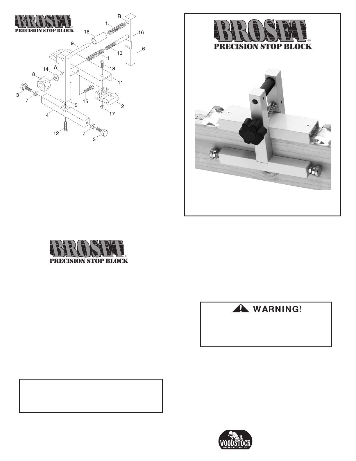
1 Spring
2 Magnification Lens
3 Knurled Screw
4 Bottom Bar
5 Front Upright Bar
6 Rear Upright Bar
7 Lock Nut
8 Handle Knob
9 Top Rod
10 Bottom Rod
11 Support Channel
12 Cap Screw M6-1 x 16
13 Phillips Screw
14 Flat Washer
15 Hex Bolt M6-1 x 8
16 Roll Pin
17 Hex Nut
18 Bushing
Assembly Instructions
1. Bolt Support Channel into slot in Front Upright
Bar using the Hex Bolt.
2. Attach Bottom Bar to Front Upright Bar using the
Hex Screw.
3. Slide Springs on to Top and Bottom Rods. Slide
the Bushing over the Top Rod and Spring.
4. Take assembled sections and slide Rods into Hole
A and B as shown in the parts diagram.
5. Slide the Flat Washer onto the Bottom Rod and
screw on the Handle Knob.
NOTE: If using the W1109 Stop Block predominantly on one side of the saw, we suggest you
remove the opposite lens and knurled screw and
keep as spares for future use.
W1109 Stop Block
Operation Instructions
1. Place the W1109 on the saw extension fence. The
thickness of the fence must be 11⁄2" wide (i.e., size of
a nominal 2x4), and a minimum of 21⁄4" in height.
2. Slide the W1109 along the fence until the hairline
on the lens is set to the desired length of cut.
DO NOT ADJUST THE POSITION OF
THE STOP BLOCK WHILE THE SAW
BLADE IS IN MOTION. SERIOUS
PERSONAL INJURY MAY OCCUR
3. Tighten Handle Knob until the W1109 is secured to
the fence.
4. Make a test cut, and measure for accuracy. To make
fine adjustments, loosen Lock Nut and screw the
Knurled Screw in or out to make the adjustment. Re-tighten the Lock Nut.
COPYRIGHT © 2002 BY WOODSTOCK INTERNATIONAL, INC.
REVISED JUNE, 2014 (TR)
www.woodstockint.com
WARNING: NO PORTION OF THIS MANUAL MAY BE REPRODUCED IN ANY SHAPE OR
FORM WITHOUT THE WRITTEN APPROVAL OF WOODSTOCK INTERNATIONAL, INC.
For further assistance contact
1-360-734-3482
PO Box 2309
Bellingham, WA 98227
 Loading...