

Page 1
200694_1
1
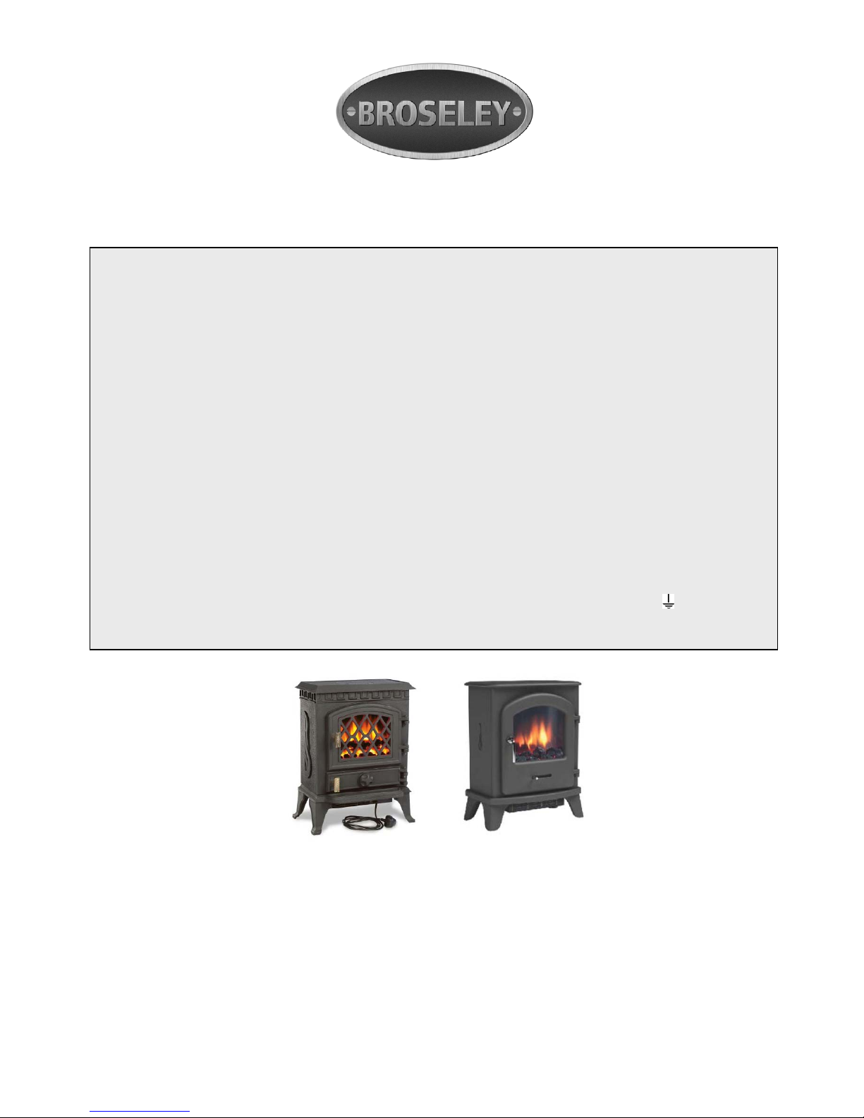
2kW Electric Stove Heater c/w Thermostat Control
instructions: Models: York Midi / Serrano
User instruction for fan heater model:
These instructions should be read carefully and retained for future reference
SETTING UP AND POSITIONING YOUR ELECTRIC STOVE
The stove will be received in two separate boxes. The first contains the cast iron stove body and the second the
Flame Effect with Heating Unit Check that the specified components are included before you start setting up your
stove.
Box 1 Box 2
1 x Cast Iron Electric Stove main body 1 x Flame Effect Unit complete with 2KW
(with transit bar fitted) Fan Heater attached.
1 x Cast Iron Stove Lid 1 x Instruction booklet.
1 x Set of Four Legs. 1 x Coal Pack
1 x Set of Four Bolts and Washers (for 1 x Glove
fixing the legs to the stove. 1 x Mains Plug & lead Assembly
Proceed as follows:
Carefully remove all packaging and protective materials. Remove and discard the ‘transit bar’ from stove body. This item stops the
sides of the stove body from moving in transit. It has been positioned into the vertical channels where the Flame Effect with Heating
Important Safety Advice:
• This heater must not be located immediately below a fixed socket outlet or connection box.
• Do not cover this heater, or obstruct the air inlet or outlet, otherwise there is a risk of overheating.
• During normal operation this appliance will emit noise from the internal fan unit.
• This appliance is not intended for use by persons (including children) with reduced physical, sensory or mental capabilities, or lack of experience and
knowledge, unless they have been given supervision or instruction concerning use of the appliance by a person responsible for their safety. Children should
be supervised to ensure that they do not play with the appliance.
• The guard used on this appliance conforms to BS1495: 1991 and satisfies the heating appliance fireguards and safety regulations 1991.
• The guard is to prevent the risk of fire or injury from burns and should not be permanently removed as the appliance would then not give full protection for
the young and infirm.
• This appliance can be used by children aged from 8 years and above and persons with reduced physical, sensory or mental capabilities or lack of
experience and knowledge if they have been given supervision or instruction concerning use of the appliance in a safe way and understand the hazards
involved.
• Children shall not play with the appliance.
• Cleaning and user maintenance shall not be made by children without supervision.
• Children of less than 3 years should be kept away unless continuously supervised. Children aged from 3 years and less than 8 years shall only switch on/off
the appliance provided that it has been placed or installed in its intended normal operating position and they have been given supervision or instruction
concerning use of the appliance in a safe way and understand the hazards involved. Children aged from 3 years and less than 8 years shall not plug in,
regulate and clean the appliance or perform user maintenance.
• Some parts of this product can become very hot and cause burns. Particular attention has to be given where children and vulnerable people are present.
Warning: this appliance must be earthed.
The wires in the main lead to this appliance are coloured in accordance with the following code:
GREEN and YELLOW Earth
BLUE Neutral
BROWN Live
As the colours of the wires in the mains lead of this appliance may not correspond with the coloured markings identifying the terminals in your plug, proceed as
follows:
• The wire, which is coloured green and yellow, must be connected to the terminal in the plug with the letter E or by the earth symbol
or coloured green or
green and yellow.
• The wire, which is coloured blue, must be connected to the terminal, which is marked with the letter N or coloured black.
• The wire, which is coloured brown, must be connected to the terminal, which is marked with the letter L or coloured red.
Page 2

200694_1
2
Unit is to be slotted into place. Remove the cast iron lid and lay the main stove body on its back. Attach the four legs using the bolts and
washers supplied. Tighten with a spanner. Stand stove upright.
SERRANO ONLY
LEGS/FEET
1. Remove the lid from the stove body
2. Lay the stove body down on a level surface so that it is secure
3. Remove the 4 leg bolt nuts in each corner of the base casting. 12mm spanner may be required
4. Remove the 4 legs from their packaging
5. Apply the legs, one at a time ensuring that each bolt is re-established and done up tightly
6. Turn the stove around so it is standing on its legs/feet
7. Remove the transit bar that is located at the rear of the stove body between the left and right side castings – This item is for transit
purposes only
ENGINE
8. REMOVE THE THERMOSTAT KNOB LOCATED IN THE MID FRONT OF THE ELECTRIC ENGINE
– Not doing so could result in the knob being scratched
9. Insert the engine with the fuel effect facing forward. The left and right brackets should slide down the left and right tram lines at the
rear of the side castings
10. If the engine does not fit left to right it might be that the side castings need releasing slightly. This simple task is done by using a
12mm spanner and slightly loosening the side panel fixing nuts. (Because each stove is manufactured individually by hand this step
may be needed on some occasions)
11. Lower the engine into the body slowly ensuring not to drop. Having one hand on the rear bottom of the engine and the other on the
front top above the flame effect will ensure full control of the engine.
12. Once the engine is lowered fully and locates onto the bottom casting it is in position
13. Open the door and return the thermostat knob to the front of the engine
14. Remove the Perspex from the door and take off protective film
15. Refit Perspex
16. Insert electric cable into engine and plug into wall
POSITIONING YOUR STOVE
This appliance should be positioned on a firm level surface. If the customer is positioning the stove in a fire surround, the customer
should establish the suitability of the surround for use with an electric stove.
Before installing the Flame Effect / Heater Unit, please ensure that your hands are clean so that no grease or dirt is
transferred to the flame effect screen.
Fit the plug & lead assembly into the socket towards the fire base and pass the plug and lead through the large rectangular cut out in
the base plate of the stove body. Slide the flame effect unit into the stove body, via the top of the stove body. The outside edges of the
flame effect unit slide into the vertical channels to the rear of each side plate.
Slide the unit down from above until the top of the back is level with the top of the side plates. The fan heater part extends through the
rectangular hole in the base plate of the stove.
DO NOT FORCE THE FLAME EFFECT AND HEATER UNIT INTO POSITION. Take care not to shear the thermostat control knob off
on the cast lip of the stove, as you slide the flame effect unit into position.
Ensure that the electrical lead and plug are not trapped between the flame effect unit and the base plate of the stove. Place the stove
in the position where you wish to use it. Take note of the section POSITIONING YOUR STOVE. When you are happy with the position
of the stove, place the stove lid onto the top of the stove body ensuring that it fits snugly into place. YOUR STOVE IS NOW READY
TO PLUG IN AND USE
Preparation for use
• Check that the supply voltage details on your fuel effect fire are in accordance with your electricity supply. Your fire is fitted with a
plug incorporating a 13amp fuse. In the event of replacing the fuse in the plug supplied, a 13amp fuse approved by ASTA to BS
1362 must be used.
• Before switching on, please read the following operation instructions:
Coals/Pebbles:
This fire is supplied with a one piece fuel bed
Thermostat:
The thermostat is mounted behind the ash pan door of the unit and can be used to control the heat output to maintain a constant room
temperature to suit user requirements. This will ensure that excessive heat is not produced unnecessarily.
To set the temperature:
The knob is marked with numbers to indicate the maximum and minimum temperature positions. Start with setting 9 and when the room
has reached a desired level turn the knob slowly to left until the thermostat ‘clicks off’. The thermostat will then maintain the room at the
selected level. To increase the temperature, turn knob back to right to a higher setting.
Note: - It is possible that if the room temperature is higher than the thermostat setting it will not come into operation and the
heater will remain off until the temperature of the room cools.
Page 3

200694_1
3
Manual Operation – Located behind the ash pan door
• The first switch marked with a light bulb controls the lamp and flame effect.
• The next two switches operate the fan convector heater. To use the heater the middle of the three switches marked O/I
(O is off, I is on) should be operated first for 1 kW of heat. The right hand switch also marked O/I should be used together
with the middle switch to give 2kW of heat.
• Note’ lamp’ switch must be in the ‘on’ position for heater to function.
Safety thermal cut-out
The appliance is fitted with an Electronic Safety Control (E.S.). This is a safety device, which switches off the fire if, for any reason, the
appliance overheats. The E.S. Control can only be re-set after the appliance has cooled down, in order to re-set the E.S. Control
proceed as follows:
• Switch off the appliance and leave for approximately 5-10 minutes.
• Switch on appliance and the E.S. Control will re-set.
• Ensure that the appliance is functioning correctly. If the E.S. Control operates again, it is advisable to have the appliance checked
out by a competent Electrician.
CAUTION: In order to avoid a hazard due to inadvertent resetting of the thermal cut out, this appliance must not be supplied through
an external switching device, such as a timer, or connected to a circuit that is regularly switched on and off by the utility.
PLEASE NOTE THAT THIS APPLIANCE USES A MOTOR TO OPERATE THE FLAME EFFECT AND THAT IT MAY BE POSSIBLE
TO HEAR IT WHERE THE BACKGROUND NOISE IS VERY LOW. THIS IS NORMAL AND SHOULD NOT BE A CAUSE OF
CONCERN.
Maintenance
Warning: Before undertaking any maintenance or cleaning disconnect appliance from main supply. Only competent persons
should service / repair appliances.
Changing Bulbs
Undo the main stove door. Remove any loose coal or logs from the fuel bed and then gently lift out the fuel bed. Lift the fuel bed clear to
give access to the two lamps underneath. Unscrew and replace the damaged bulbs holding the body of the lamp holder if necessary to
prevent rotation and replace the fuel bed by gently sliding back into the recess. Replace loose coal or logs back onto the fuel bed.
(Bulbs are 11W E14 SES Mini Spiral available through customer services)
The area around the fire should be kept free of any materials such as lint or house dust (i.e. Animal hair/ carpet fibres) that
could be drawn into the internal workings of the appliance and hence affect the performance. We recommend that you clean
around the fan grille housing at regular intervals. This can be done using standard vacuum cleaner and suitable attachment.
Please note: if the supply cord on this appliance is damaged it must be replaced by the manufacturer, Authorised Service Agent, or a
qualified person to avoid a hazard.
Note: To prevent scratching of the front screen, this appliance should be cleaned with a damp cloth only.
Fault finding – symptoms and cure.
It is highly unlikely you should have a fault with your heater, but should there appear to be a problem, please refer to the following
checklist of our most frequent questions from customers. If these do not answer your query please contact your retailer, or call us.
No light effect
Please check – does the heater still work? If YES – it will almost certainly need a new LED unit (See maintenance section)
If NO – has the heater cut-out operated? To protect against overheating please refer to safety cut-out section above. If still not working,
first change the 13amp fuse in the plug with one which you know works. Secondly, check the wall socket by plugging a table lamp that
you know works on another socket. If this does not work get an electrician to check the socket.
Page 4
200694_1
4
Electric Fire Guarantee
This fire complies with the European Safety Standards (LVD) EN60335-2-30 and the European Electro Magnetic Compatibility
(EMC) En55015, EN60555-2 and EN60555-3 which covers the essential requirements of the EEC Directives and 89/336
Waste electrical products should not be disposed of with household waste. Please recycle where facilities
exist. Check with your local authority or retailer for recycling advice.
Broseley Fires Ltd.
Customer Services
Knights Way,
Battlefield Enterprise Park,
Shrewsbury,
SY1 3AB
Tel: 01743 461444
Fax: 01743 461446
Email:[email protected]
Broseley Fires Ltd. (the ‘Company’) provides a Twelve month guarantee in respect of electric fire (the
‘Product’) ranges.
1. The Twelve month Guarantee applies to:
a. All products in the ranges manuf actured by the ‘Company’ (but subject to the exceptions below):
where
b. The product has been purchased and installed within the UK and in respect of
c. The initial installation: and in favour of
d. The original purchaser
2. Proof of Purchase must be retain ed by the Purchaser
3. The Twelve month Guarantee does not apply to:
a. Damage or inferior workmanship practices whilst the ‘Product’ is being installed
b. Damage caused by mis-use of the ‘Product’ or where normal standards of care and use have
not been complied with.
c. Damage through a malfunction or an inadequately installed electric fire.
d. Damage or defects due to mis-use, accident or unauthorised alterations.
4. During the year after the ‘Product’ has been supplie d, the Guarantee cover s the make go od (whether by
repair or replacement at the Company’s option) of defects arising from defective manufacture of
materials of ‘Product’ covered in Para 1 all at no cost to the purchaser on the proviso:
a. The Product has been installed as Be Modern recommendations
b. The Purchaser uninstalls the Product and makes it available for collection by Be Modern.
This Guarantee does not affect your statutory rights
On requiring service the purchaser should contact the retailer who supplied your product who will assist
and advise you as necessary.
 Loading...