

Page 1

Broseley Fires Ltd.
Canterbury & Lincoln Balanced Flue Stove
(Model : PD-08-002)
Remote Control
(FITTED AS STANDARD)
For use on Natural Gas (G20) at a supply pressure of 20mbar
GB and IE.
Contact Details:
Broseley Fires Ltd
Knights Way
Battlefield Enterprise Park
Shrewsbury
SY1 3AB
Tel: +44 (0) 1743 461444
Fax: +44 (0) 1743 461446
Email:
Warranty:
In the unlikely event of a defect in materials or workmanship occurring within one year of
purchase, please contact the shop from where the appliance was purchased.
Any claims under this warranty must be made through the retailer from whom the product
was purchased.
As the purchaser’s contract of sale is with the retailer, Broseley Fires are unable to enter
into discussions with the purchaser until the retailer has inspected any claim and deemed
it to be valid.
Broseley Fires reserve the right to refuse service or make a charge for any service call,
when a defect is due to installation error or misuse.
Installation & Servicing
MUST BE LEFT WITH THE END USER
User Instructions.
Instructions.
Page 2
Extended warranty (if purchased) commences after the first year; please see separate
registration for further information.
Appliance Details:
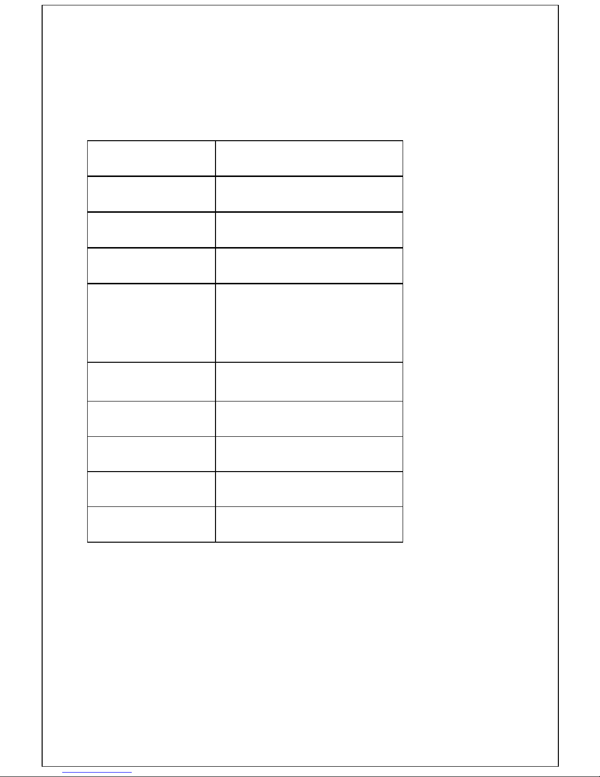
For future reference, please complete the following information at the time of installation.
Model and Serial Number details may be found on the data plate as shown.
PRODUCT SERIAL
NUMBER
MODEL: CANTERBURY
or LINCOLN
FUEL EFFECT:
LOG or COAL
DATE OF
INSTALLATION
INSTALLERS DETAILS
GAS SAFE
REGISTRATION
NUMBER
DUE DATE OF FIRST
SERVICE
DATE OF 2nd SERVICE
DATE OF 3rd SERVICE
DATE OF 4th SERVICE
Page ii
Page 3

Contents
1. GENERAL INFORMATION............................................................................................. 1
2. USER INSTRUCTIONS................................................................................................... 3
2.1. Location of Pilot Burner ................................................................................... 3
2.2. Lighting Procedure .......................................................................................... 4
2.2.1. Lighting Procedure (Manual Control) ......................................................... 5
2.2.2. Lighting Procedure (Remote Control) ........................................................ 6
2.3. Battery Replacement (Remote Control) .......................................................... 8
2.3.1. Handset ..................................................................................................... 8
2.3.2. Receiver Unit ............................................................................................. 8
2.4. Home Improvements ....................................................................................... 9
2.6. Cleaning and Care Instructions ..................................................................... 10
2.6.1. Painted Metal Surfaces ............................................................................ 10
3. INSTALLATION INSTRUCTIONS ................................................................................ 11
3.1. General Safety Requirements ....................................................................... 11
3.2. General Dimensions ...................................................................................... 11
3.3. Flue Options .................................................................................................. 12
3.4. Technical Data .............................................................................................. 12
3.5. Appliance Location ........................................................................................ 13
3.5.1. Clearances to Combustible & Non Combustible Surfaces ......................14
................................................................... Error! Bookmark not defined.
3.6. Flue Terminal Location .................................................................................. 18
3.7. Flue Components .......................................................................................... 19
3.8. Contents Checklist ........................................................................................ 19
3.9. Installation Procedure ................................................................................... 20
3.9.1. Pre-Installation Procedure ....................................................................... 20
3.9.2. Assembling the cast iron Stove surround and Burner 21
3.9.3. Preparing the installation 21
3.9.4. Installation procedure for non combustible walls .........................................
3.9.5. The Gas Supply ....................................................................................... 23
3.9.6. Fuel Effect Layouts .................................................................................. 24
3.9.7. Coal Effect Layout ................................................................................... 25
3.9.8. Log Effect Layout ..................................................................................... 26
3.9.9. Fitting the Glass Panel and Frame .......................................................... 27
3.9.10. Assembly of the cast iron stove components .......................................... 28
3.9.11. Remote control ............................................................................................
3.9.12. Commissioning ........................................................................................ 29
3.9.13. Fitting the Trim .............................................................................................
3.9.14. Instructing the User .................................................................................. 30
4. SERVICING INSTRUCTIONS ....................................................................................... 31
4.1. General Requirements .................................................................................. 31
4.1.1. Cleaning the Fuel Effect, Fire-bed and Combustion Chamber ................ 32
4.1.2. Cleaning Lining Board Panels ................................................................. 32
4.1.3. Care of Lining Panels .............................................................................. 32
4.2. Replacing Parts ............................................................................................. 33
4.2.1. Burner Components Removal and Replacement .................................... 33
4.2.2. Injector Replacement ............................................................................... 33
4.2.3. Control Valve Replacement (Manual Control /Remote Control) .............. 34
4.2.5. Motor Replacement (Remote Control Model) .......................................... 35
4.2.6. Replacing the Receiver (Total Control) ........................................................
4.2.7. Programming Handset to Receiver (Total Control) ......................................
4.3. Installation and Operational Troubleshooting .......................................... 36
Page i
Page 4

GUARANTEE.....................................................................................................39
Page ii
Page 5

1. GENERAL INFORMATION
Introduction
1. This appliance is suitable for installation in GB and IE and should be installed in
accordance with the rules in force.
In GB, the installation must be carried out by a Gas Safe Registered Installer. It must be
carried out in accordance with the relevant requirements of the:
• Gas Safety (Installation and Use) Regulations.
• The appropriate Building Regulations either The Building Regulations,
The Building Regulations (Scotland), Building Regulations (Northern Ireland).
Where no specific instructions are given, reference should be made to the relevant British
Standard Code of Practice (see item 2).
In IE, the installation must be carried out by a Competent Person and installed in
accordance with the current edition of I.S.813 “Domestic Gas Installations”, the current
Building Regulations and reference should be made to the current ETCI rules for el ectrical
installation.
On completion of an installation in IE, it is necessary to complete a “Declaration of
Conformity” to indicate compliance to I.S.813.
2. In other EC countries, the equivalent rules in force at the time must be used.
3. It is important for correct combustion of this fire, that the imitation fuel is placed in
accordance with the instructions given in this and associated booklets. Only approved
imitation fuel, available from Broseley Fires Ltd., should be used with this appliance.
4. It is recommended that a fire guard complying with BS 8423 be fitted for the protection of
young children, the elderly or infirm.
5. Ensure that curtains are not positioned above the appliance, and there is at least 300mm
between the sides of the appliance and any curtains.
6. Clearances to combustible materials must be observed, and only fitted in accordance with
the instructions given in this and associated booklets.
7. The user is warned not to remove the glass panel or to disturb the fuel bed. Any servicing
of the appliance must be carried out by a Gas Safe registered installer.
8. If any cracks appear in the glass panel, do not use the appliance until the glass
panel has been replaced. (by a qualified installer).
9. Ensure that the flue terminal is always kept clear of any obstructions (e.g. shrubs, plants,
objects leaning against it, etc.).
10. It is important for the fire to be serviced regularly. An annual service is required.
Page 1
Page 6

Ventilation Requirements
1. This appliance does not require any additional fixed ventilation in the room where it is
fitted. It is a balanced flue appliance, whereby the air for combustion is drawn in from the
outside, and the products of combustion are evacuated to the outside through a concentric
flue duct system. (supplied)
2. In other EC countries, equivalent rules in force at the time of installation must be used.
Gas Supply
1. This range of gas fires are only suitable for use with Natural Gas (G20) at 20mbar supply
pressure. Conversion to Propane (G31), at 37mbar supply pressure, is not possible.
2. A separate means of isolating the gas supply should be provided near to the appliance
this is to facilitate servicing. An isolation valve (with a pressure test point) has been
supplied for this purpose.
Electrical Supply
Not applicable to this range of appliances, as no mains power is required.
Efficiency Declaration
The efficiency of this appliance has been measured as specified in BS EN 613:2001, and the
result is 74.7% (83% net) for Natural Gas. The gross calorific value of the fuel has been used
for this efficiency calculation. The test data from which it has been calculated, has been
certified by Gastec at CRE Ltd. The efficiency value may be used in the UK Government
Standard Assessment Procedure (SAP) for energy rating of dwellings.
Hot Surfaces
All parts of this appliance, including any handles, get very hot during normal use, they are
classed as working surfaces. It is therefore recommended that a suitable fireguard be used for
the protection of young children, the elderly and infirm.
Page 2
Page 7
2. USER INSTRUCTIONS TO BE LEFT WITH CUSTOMER
2.1. Location of Pilot Burner
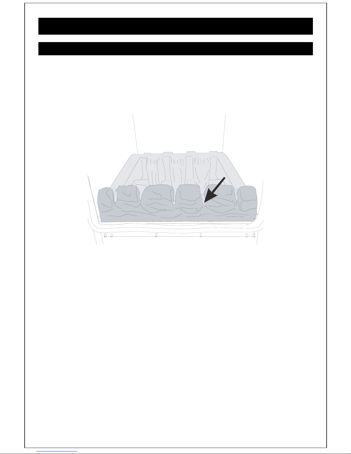
The pilot assembly is located just to the right of centre of the appliance, in front of the main
burner.
The pilot flame can be viewed by looking downwards over the top of the front ceramic
FIGURE 1).
(see
Pilot
FIGURE 1. PILOT LOCATION
Page 3
Page 8
2.2. Lighting Procedure
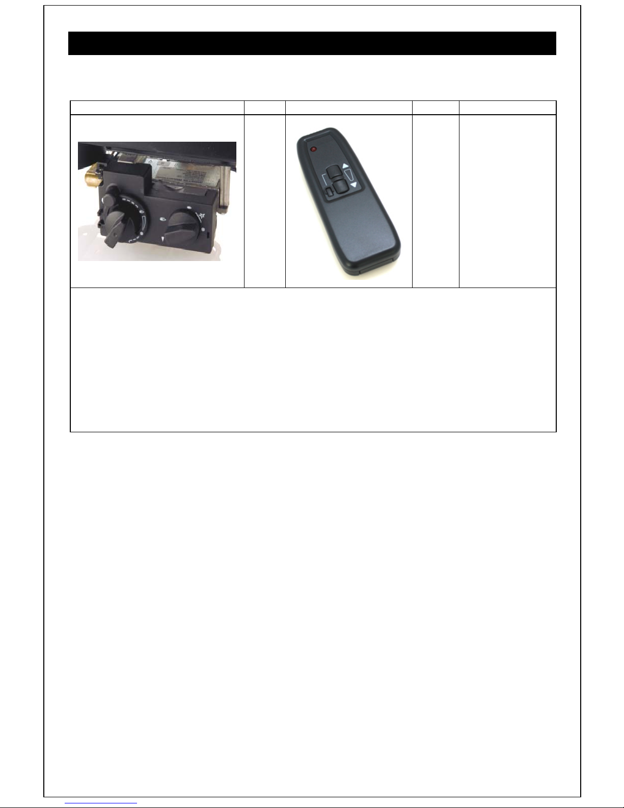
Your fire is fitted as standard with a remote control valve. Follow the appropriate operating
instructions in the appropriate section.
Control Valve Operation Control Type
REMOTE
+
The control valve allows the fire to be lit manually. Once the pilot is lit, the remote control
can be used to increase and decrease the gas rate to the burner.
=
CONTROL
By pressing the buttons in short bursts you will be able to adjust the gas rate in small steps.
Please read the full instructions for the valve and remote operation below, before
attempting to ignite and extinguish your fire.
Your appliance can also be controlled manually, using the Gas Rate Adjusting knob.
Page 4
Page 9
2.2.1. Lighting Procedure (M anual Control)
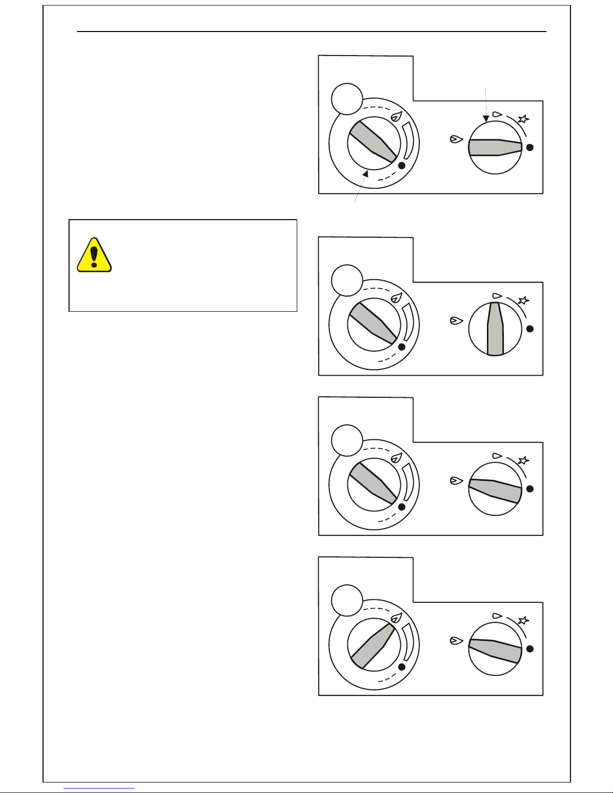
1. From the OFF position, ‘¦’ indicated in
FIGURE 3 push the IGNITION KNOB in
turn it anticlockwise to the pilot flame
position, as shown in FIGURE 3. During
this process, the spark ignition will have
operated and lit the pilot flame. On
ignition of the pilot flame, continue to
depress the ignition knob for a further
15 - 20 seconds, then slowly release.
The pilot flame should stay alight. If the
flame goes out repeat the procedure
above to establish the pilot.
NOTE: No attempt should be
made to relight the fire for at
least 3 minutes after the pilot
flame has been extinguished
either intentionally or
unintentionally.
Gas rate adjusting knob
FIGURE 2 – OFF POSITIONS
Ignition knob
2. Once the Pilot is established, turn the
IGNITION KNOB further anticlockwise
to the main burner operation position,
as shown in FIGURE 4.
3. Turn the GAS RATE ADJUSTING
KNOB fully anticlockwise (until you
reach the stop position) i.e. the
maximum gas rate. See FIGURE 5.
4. The main burner will have cross-lit from
the pilot and the fire will be at maximum
gas rate.
5. No w the gas rate can be adjusted to the
desired setting, by turning the GAS
RATE ADJUSTING KNOB to any
position between the pre-set high and
low positions.
6. To switch off the main burner, but leave
the pilot alight, turn the IGNITION
KNOB to the ‘Pilot burner only Position’
as shown in FIGURE 3. The appliance
may be left in this standby mode if
desired.
FIGURE 3 – Pilot burner only
FIGURE 4 – Main burner operational, but gas flow off
7. To turn the pilot off, turn the Ignition
Knob on the control valve fully
clockwise to ‘¦’ position.
FIGURE 5 - Main Burner operational & Maximum Gas
Rate
Page 5
Page 10
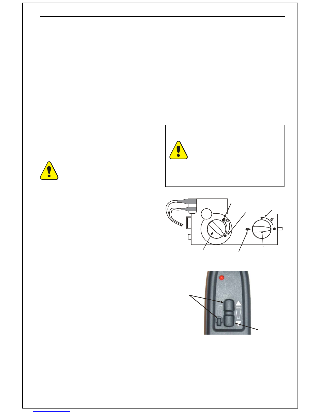
2.2.2. Lighting Procedure (Remote Control)
In order to be able to use the remote control, to adjust the gas rate of the appliance to the
desired level, the pilot must first be lit manually. This is described above in
PROCEDURE, MANUAL CONTROL and repeated here, steps 1,2 & 3. Once the pilot is established,
the remote control handset is operational, as well as the manual controls on the valve.
1. From the OFF position, ‘¦’ indicated in
FIGURE 3, push the IGNITION KNOB in
turn it anticlockwise to the pilot flame
position, as shown in FIGURE 3. During
this process, the spark ignition will have
operated and lit the pilot flame. On
ignition of the pilot flame, continue to
depress the ignition knob for a further 15
6. The fire can safely be left in this position
at all times, however to prevent
unauthorised or accidental use (say by
children) it is recommended to turn the
IGNITION KNOB to the pilot flame
position by turning it 90 degrees
clockwise. To turn the pilot off, turn the
IGNITION KNOB fully clockwise.
- 20 seconds, then slowly release. The
pilot flame should stay alight. If the flame
goes out repeat the procedure above to
establish the pilot.
NOTE: The clicking sound
made by the valve, when using
the remote handset, is the
operation of the valve clutch.
NOTE: No attempt should be
made to relight the fire for at
least 3 minutes after the pilot
flame has been extinguished
either intentionally or
It indicates either the maximum
or minimum rotation of the gas
rate adjustment knob has been
reached.
unintentionally.
2. Once the Pilot is established, turn the
IGNITION KNOB further anticlockwise to
the main burner FULL RATE position, as
shown in FIGURE 4.
2.2.1 LIGHTING
FULL RATE
POSITION
MAIN BURNER
OFF POSITION
PILOT ONLY
POSITION
3. From this point onwards, the handset
can be used to adjust the gas rate of the
appliance to the desired level between
the pre-set high and low positions.
4. Using the HANDSET, (as shown in
FIGURE 7) By pressing the top and
small buttons together (to increase the
gas rate) and the lower button only (to
decrease the gas rate) the valve can be
manipulated to select the desired gas
rate between maximum and minimum.
By pressing the larger buttons in short
bursts you will be able to adjust the gas
rate in small steps.
5. To turn the fire off, continuously press
the lower big button, until the flame dies
down and clicks can be heard from the
valve. Release the button as soon as the
clicks are heard. The fire is now in ‘pilot
only’ position, as shown in FIGURE 3.
Press these
two buttons
together to
increase
gas rate
GAS RATE
ADJUSTMENT
KNOB
FIGURE 6 – Gas Valve
FIGURE 7 - Handset Operation
MAIN BURNER
OPERATION
IGNITION
KNOB
Press this
button to
decrease
gas rate
Page 6
Page 11

This page is intentionally left blank
Page 7
Page 12
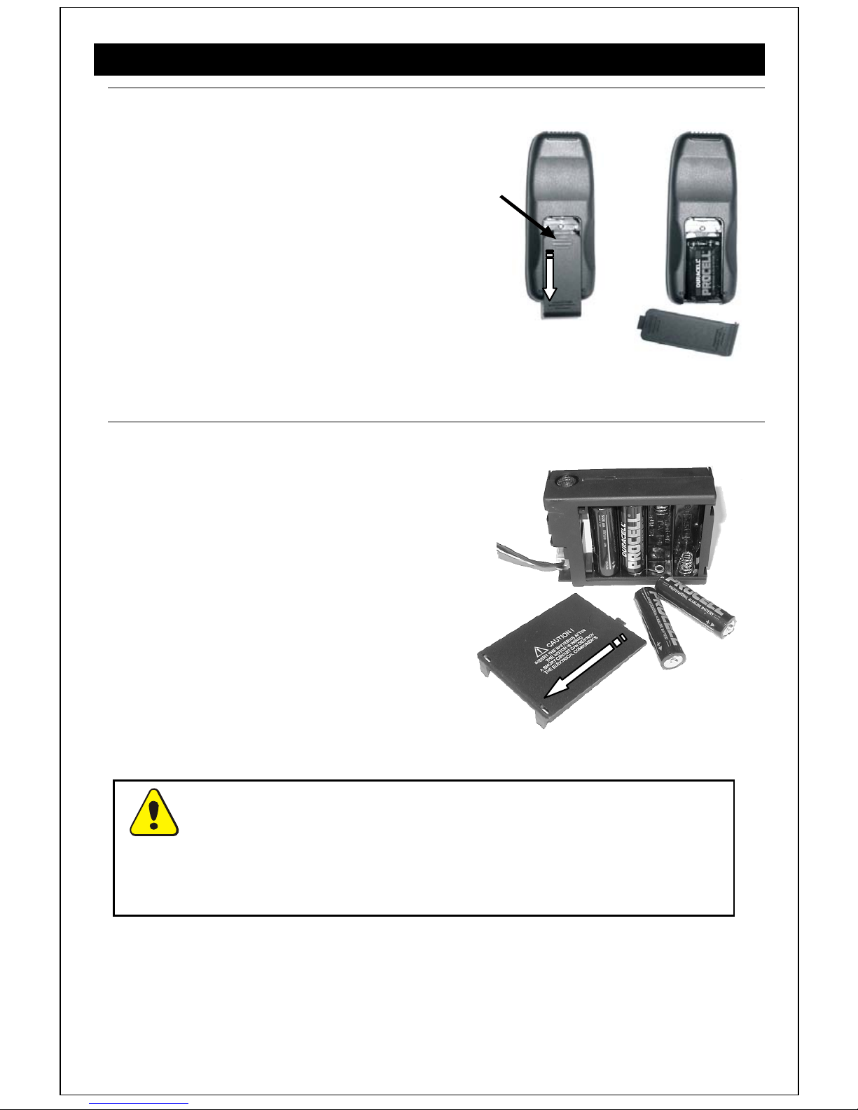
2.3. Battery Replacement (Remote Control)
2.3.1. Handset
1. On the reverse of the handset, remove
the battery cover by pressing in at the
top of the cover and sliding it down. (See
FIGURE 8)
2. Remove and unclip the old battery and
replace with a new PP3 9V battery.
3. Replace the cover by sliding it back up.
Press here and
slide d own
FIGURE 8 HANDSET BATTERY REPLACEMENT
2.3.2. Receiver Unit
1. Remove the receiver unit from under the
stove. Remove the battery compartment
cover by sliding it back. (see FIGURE 9).
2. Remove and unclip the old batteries and
replace with new ones, (4 x AA 1.5V)
ensuring they are inserted in the correct
polarity.
3. Replace the cover on the receiver unit,
ensuring that it is securely closed.
4. Return the receiver unit to its original
mounting position.
With the exception of battery replacement, the receiver / battery holder must
be placed on the floor, (hearth) under the appliance. It can be positioned towards
the front of the hearth, if you wish to see the ‘handset in use light’ on the front of the
unit, or pushed to the back of the hearth, for neatness.
FIGURE 9 RECEIVER BATTERY REPLACEMENT
Page 8
Page 13
2.4. Home Improvements
NOTICE: Discolouration of wall surfaces near the appliance
Generally, heating appliances w ill create warm air con vection currents that
will transfer heat to any surface against which they are located.
Some soft furnishings (including blown vinyl wallpapers) may not be
suitable for use, where they are likely to encou nter temperatur es above the
normal room level. For this reason, the manufacturer’s advice should be
sought before using this type of wall covering adjacent to any heating
appliance.
The likelihood of wall staining, caused fr om con vection air currents, w ill b e
increased in areas where high levels of tobacco smoke, or other
contaminants, exist.
Page 9
Page 14

2.5. Cleaning and Care Instructions
2.5.1. Painted Metal Surfaces
These surfaces should be dusted regularly and any marks removed with a soft damp cloth. Do
not leave the appliance wet. A soft brush may be used to clean dust deposits fro m any cast
iron surface. This should be done only when the appliance is cold. Cans of touch-up paint are
available to re-paint the cast surfaces of the appliance.
Any other maintenance of the product must be carried out by a Gas Safe engineer.
2.5.2 Glass Surfaces
Only clean the glass when the appliance is cold and the pilot is not lit. The outside of the glass
can be wiped clean with a soft damp cloth. Do not leave the appliance wet. If the inside of the
glass is dirty, please get a Gas Safe engineer to investigate, and clean the glass.
Page 10
Page 15
3.0 Installation Instructions for use by the ‘Gas Safe’ engineer
THIS APPLIANCE MUST BE INSTALLED AND COMISSIONED BY A ‘GAS SAFE ENGINEER’
Before installation, ensure that the local distribution conditions, identification of the
type of gas and pressure, and the adjustment of the appliance are compatible.
3.1 General Safety Requirements
Before commencing installation, ensure that the intended installation will comply
with details in General Information on Page 1.
The installation of the fire should follow the recommendations of the following
current British Standards (or equivalent):
BS 6891 Pipe work Installation
BS 5440: Pts 1 & 2 Flues and Ventilation
IGE/UP/7 IGE document for gas installations in Timber
Frame Buildings (Available from The Institute of
Gas Engineers and Managers)
Combustible shelves or materials must only be fitted above the stove as
described later in this section.
Ensure that curtains are not positioned above the appliance and there is at least
300mm between the sides of the appliance and any curtains.
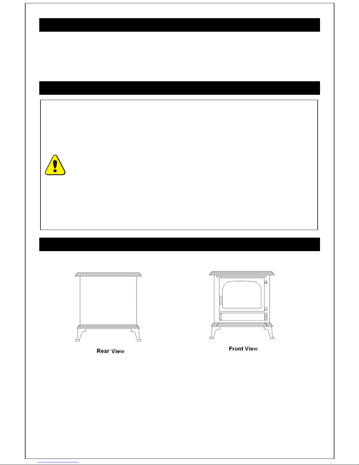
3.2 General Dimensions
FIGURE 10. General Dimensions (image above is of the Canterbury)
LINCOLN CANTERBURY
Height 660mm 655mm
Depth (not inc. Ash Lip) 280mm 270mm
Width 590mm 595mm
Weight 64kg 66Kg
Page 11
Page 16
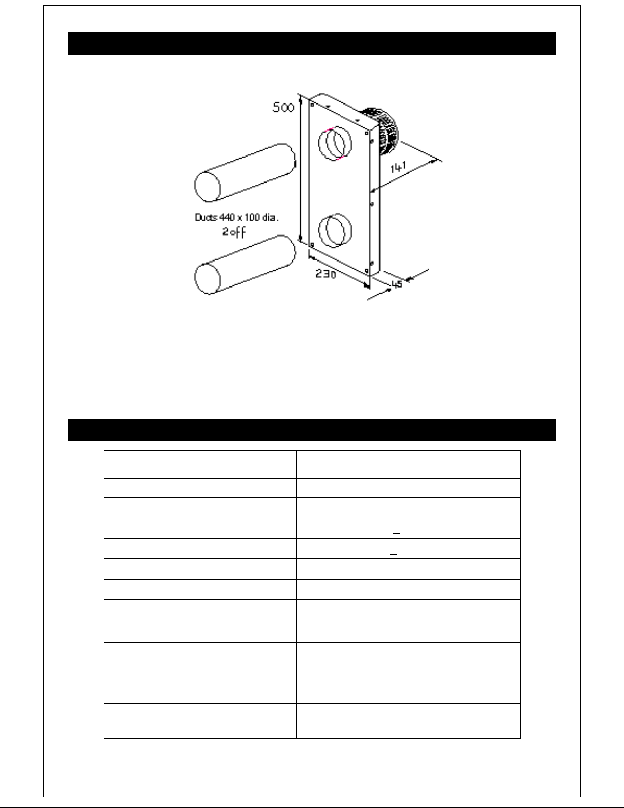
3.3 Flue Options
FIGURE 11 Flue Pipe and Air Box with terminal (all dimensions in mm)
The horizontal length of the ducts is measured from the rear of the outer firebox of the
appliance, to the external face of an external wall. The maximum length allowed is 965mm. As
the stove must be spaced at least 75mm from the rear wall, the maximum wall thickness that
can be accommodated is 890mm.
3.4 Technical Data
TECHNICAL DATA Natural Gas (G20)
Nominal maximum heat input (hot) 5.1kW (gross)
Nominal minimum heat input (hot) 2.3 kW (gross)
Setting pressures (cold) Max 10.0 + 0.5 mbar
Setting pressures (cold) Min 2.0 + 0.2 mbar
Gas Rate 0.486 m³/h
Injector Size Multiport
Gas Inlet Connection 8 mm Compression
7x
ø 0.77mm
Pilot Polidoro 440.0333.11
Pilot Injector
Efficiency 72% (80% net) for Natural Gas (Class 1)
Weighted NOx 143mg/kWh (Class 3)
Max / Min length of flue duct 1000mm / 150mm
Standard length of duct supplied 440mm
Page 12
TABLE 1
2x
ø 0.25mm
Page 17

3.5 Appliance Location
The appliance is designed to be fitted through a non combustible back panel mounted on an
outside wall. Alternatively the appliance may be fitted into a false chimney breast, a deep
rebated fire surround or a redundant fireplace, sited on an outside wall. The appliance may be
sited at floor level or as a raised ‘hole in the wall’ installation.
In all installations, we recommend a non combustible back panel is fitted behind the appliance,
taking into consideration the 75mm clearance requirement between it and the rear of the
appliance. A spacer is supplied for this purpose. We do not recommend installing the
appliance against a plastered wall without a back panel. The non combustible panel should
extend at least 300mm above the top of the stove and be at least the width of the stove, plus
150mm each side. While the temperature of the wall behind and above the stove does not
reach a dangerous level, there is still a risk that the plaster may crack, or the wall covering
may be marked.The fire must be fitted on a flat, non-combustible base. A non-combustible
hearth, with minimum dimensions shown in the figures below, should be provided in front of
the fireplace opening where relevant. This is required to protect combustible floor coverings
from radiant heat from the fire. If the appliance is to be installed with its base more than
100mm above floor level, the hearth projection in front of the appliance may be reduced to a
minimum that is aesthetically pleasing.
The different types of wall materials have different installation requirements. If the appliance is
to be installed in a timber framed building, the recommendations of IGE/UP/7 Edition 2 Gas
installations in timber framed and light steel framed buildings available from the IGEM
must be followed.
Page 13
Page 18
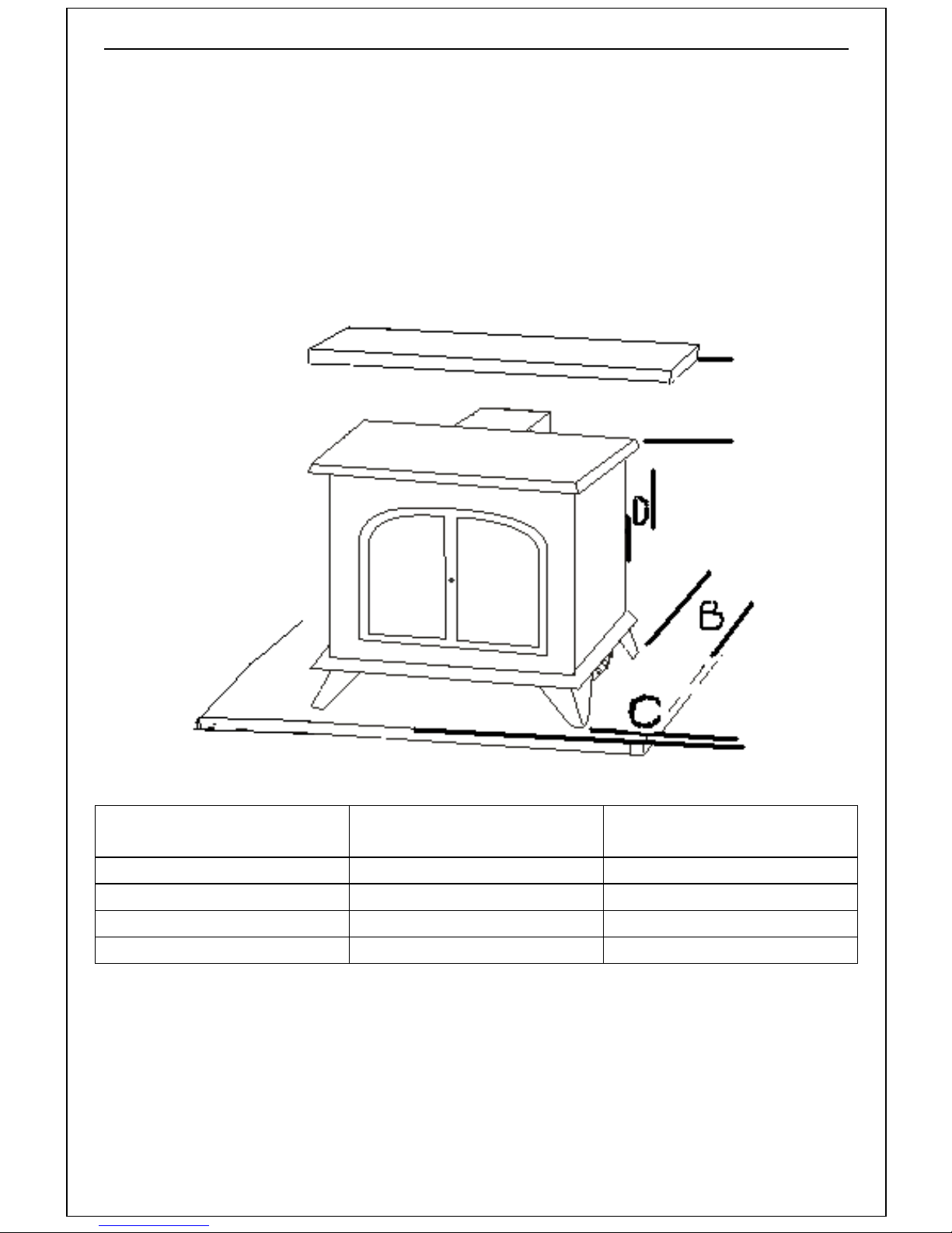
3.5.1 Clearances to Combustible & Non Combustible Surfaces
A
1. Shelves or mantels made from combustible materials should not be placed closer than
300mm above the appliance.
2. Light coloured and resin mantels may discolour in time. The temperature rating of any
surround should be checked before use.
NOTE: Please see diagrams A & B on pages 15 & 16, to see the
temperatures we have recorded, with the appliance at maximum
output. These are rises in temperature above the ambient.
B
CLEARANCE TO A
COMBUSTIBLE
A (above) 300 mm 150 mm
B (each side) 150 mm 100 mm
C (in front) 50 mm 50 mm
D (behind) 200 mm 75 mm
The hearth must be made from a suitable, non-combustible
material such as board, steel, tiles or glass. The minimum
thickness of this material is 12mm. Please ens ure that the hearth
CLEARANCE TO A
NON COMBUSTIBLE
can accommodate the weight of the appliance and its
unsupported flue components.
Page 14
Page 19
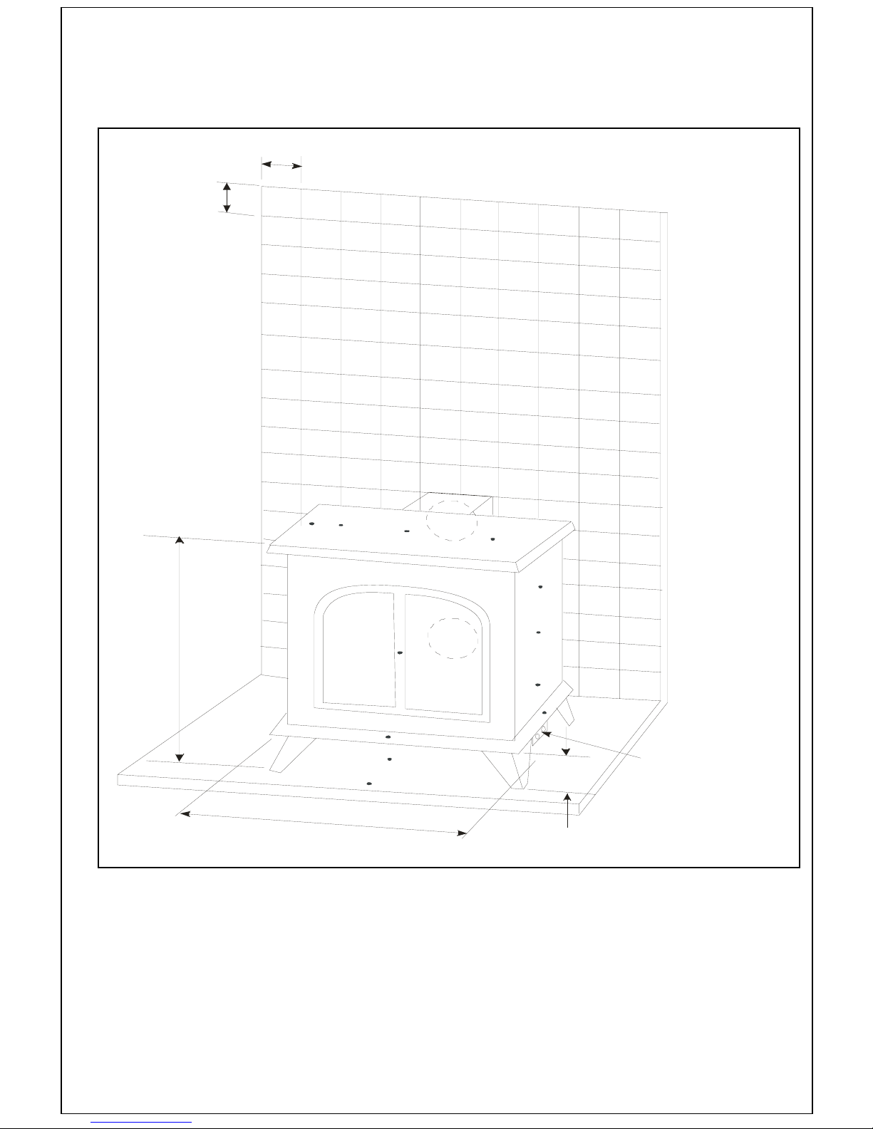
‘Diagram A’ below shows the increase in temperature of the surrounding
walls, in degrees Celcius, with the appliance at maximum output.
13
15
18
o
C.
The ambient temperature of the room was 22
100
mm
0
m
0
1
m
13
13
17
15
18
18
0
6
6
12
16
5
113
9
30
0
43
147
132
10
133
21
8
20
24
28
37
44
45
21
25
30
40
55
132
20
24
28
37
44
45
118
46
36
25
17
130
13
32
14
10
12
10
1983
11
9
8
VALVE BODY
10
CONTROL KNOBS
8
DIAGRAM A - increase in temperature of the surrounding walls
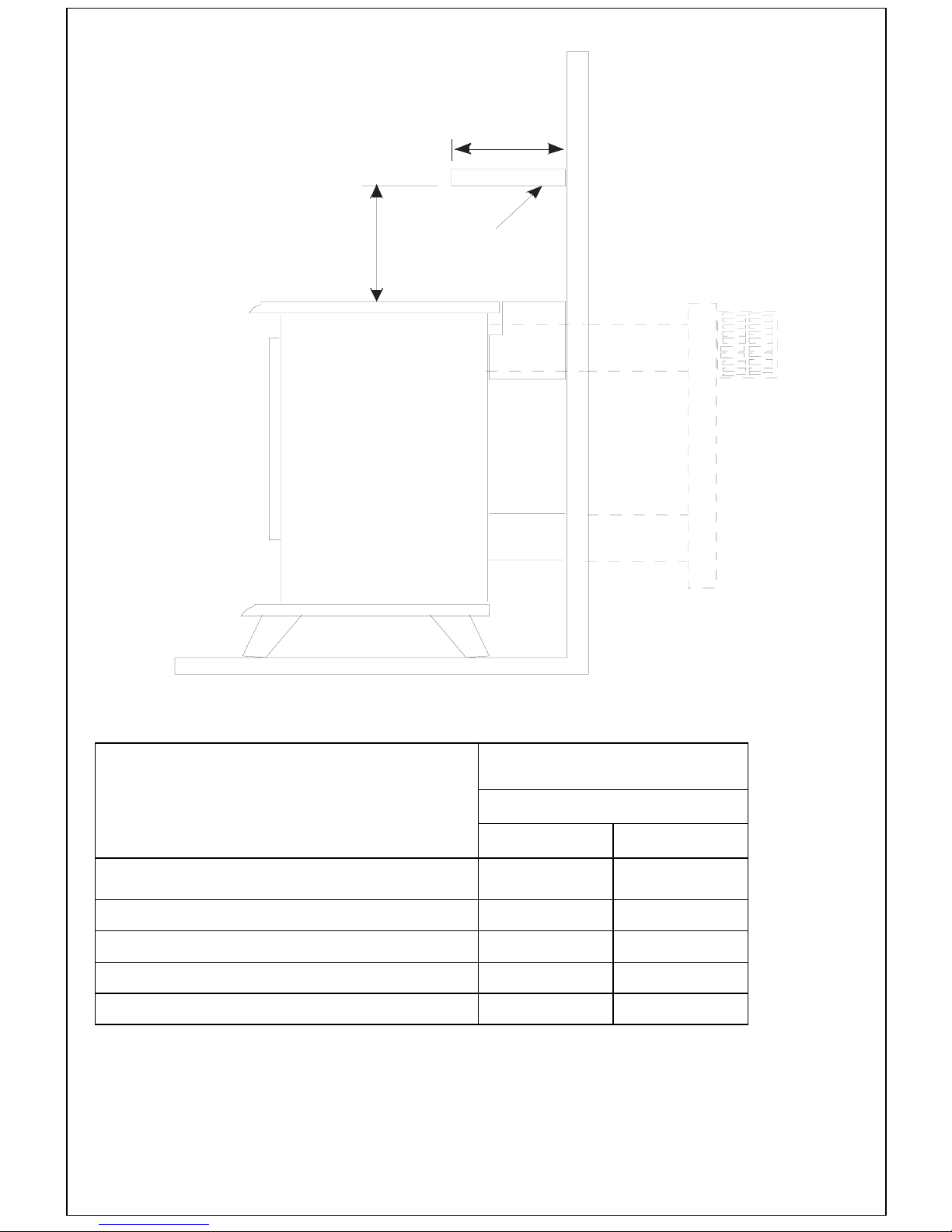
‘Diagram B’ below shows the increase in temperature of a decorative shelf,
(not supplied) in degrees Celcius, with the appliance at maximum output.
The ambient temperature of the room was 24
o
C.
Page 15
Page 20
D
H
T
DIAGRAM B - increase in temperature of a decorative shelf
o
Height of Shelf above top of Stove
mm
200 49 52
300 40 46
400 39 42
500 32 38
600 26 34
Temperature Rise (T
Shelf Depth (D mm)
100 200
C)
Page 16
Page 21

Page 17
Page 22
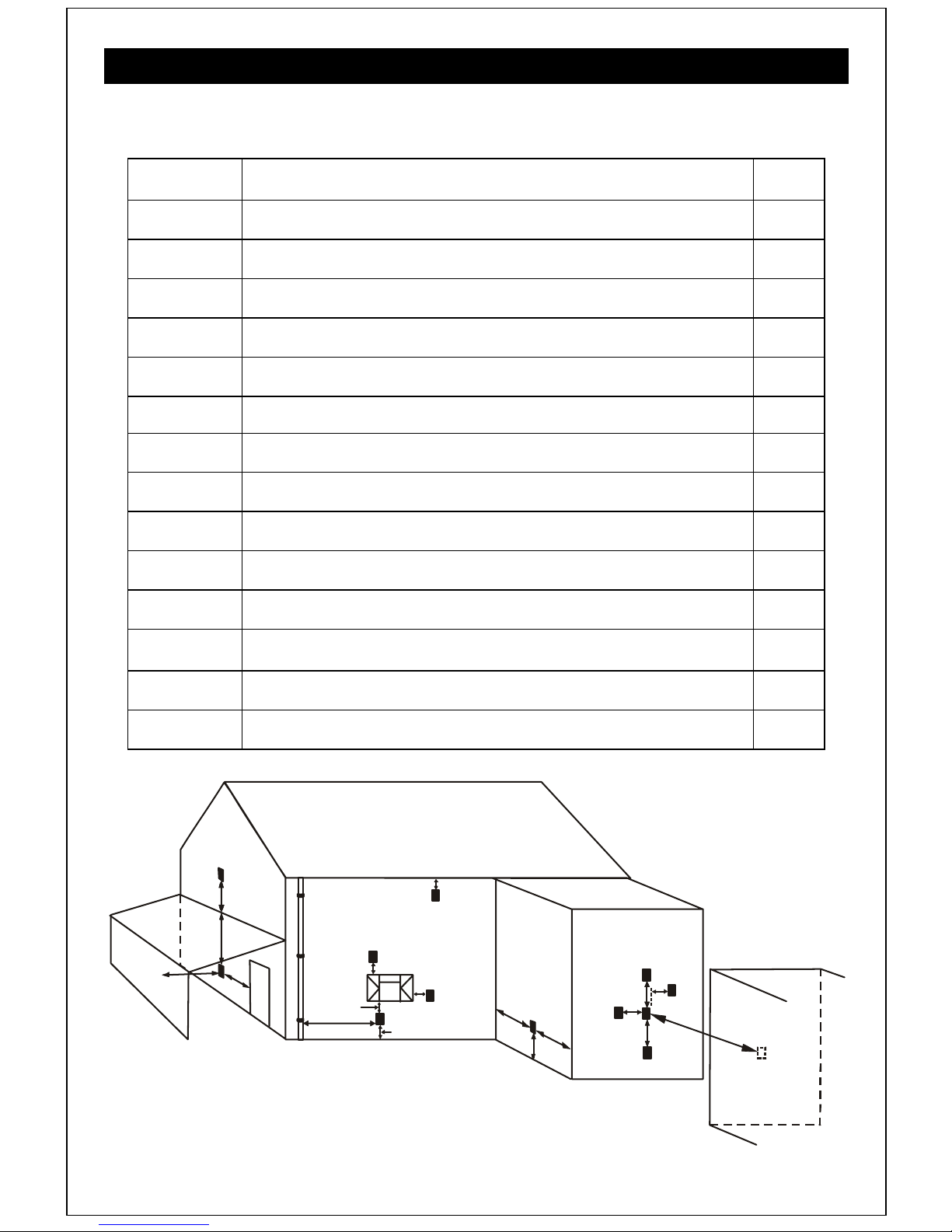
3.6 Flue Terminal Location
The minimum acceptable dimensions from the flue terminal to obstructions and ventilating
openings are shown in Table 2 and FIGURE 13.
Dimension Terminal Position
Value
mm
A
B
C
D
E
F
G
H
I
J
K
L
Directly below an opening, air brick, opening windows, etc. 300
Above an opening, air brick, opening window, etc. 300
Horizontally to an opening, air brick, opening window, etc. 300
Below gutters, soil pipes or drain pipes 300
Below eaves 300
Below balconies or car port roof 600
From a vertical drain pipe or soil pipe 300
From an internal or external corner 600
Above ground, roof or balcony level 300
From a surface facing the terminal 600
From a terminal facing a terminal 600
From an opening in the car port (e.g. door, window) into the
dwelling
1200
M
N
Vertically from a terminal on the same wall 1500
Horizontally from a terminal on the same wall 300
Table 2
I
F
L
J
G
B
A
I
D,E
C
H
H
I
N
M
N
M
K
Page 18
FIGURE 12
Page 23
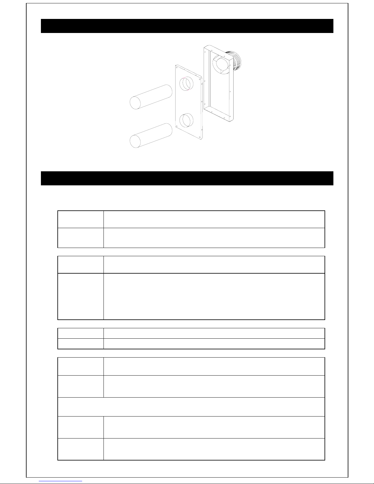
3.7 Flue Components
Ducts
Terminal / Air Duct
Wall Plate
FIGURE 13 PARTS OF THE FLUE KIT
3.8 Contents Checklist
Before proceeding with the installation of the appliance, please check the contents of the
cartons as follows:
Quantity Items in CARTON 1
1 assembly Balanced flue gas fire assembly. (with glass fitted)
Quantity Items in CARTON 2
Quantity Items in CARTON 3
Quantity Items in CARTON 4
1 bag Containing documentation, isolating valve.
1 box Imitation Coal or Log Pack
1 box Front and Rear Ceramic Mouldings
1 box
1
1
Standard flue kit containing 2x 440mm lengths ø100mm flue ducts
and an Air Box with Terminal guard.
Spacer bracket (to cover visible flue duct behind appliance.)
1 Terminal Guard
Remote Control Handset and Receiver,
1 box
4 off AA Batteries, 1 off PP3 (9V) Battery
Quantity Items in CARTON 5
1 box
Cast iron, decorative stove surround.
Page 19
Page 24
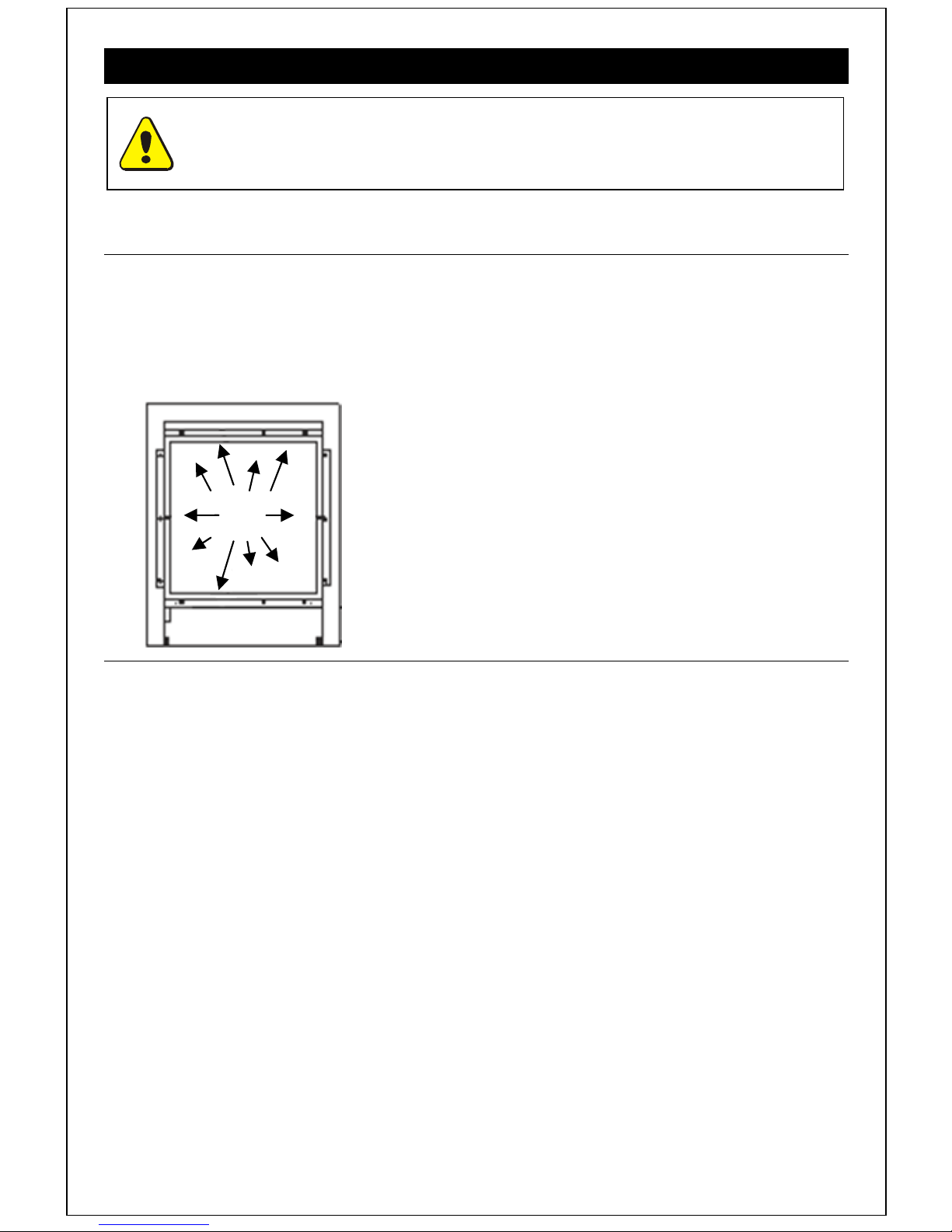
3.9 Installation Procedure
Before commencing installation, ensure that the intended installation will comply
Carefully unpack the contents of the appliance carton and check them against the checklist
given on the previous page.
3.9.1 Pre-Installation Procedure
Appliance
1. Unpack the Balanced flue gas fire assembly from its carton.
2. Using a suitable 7mm socket remove the 14off glass frame retaining nuts and lift off the
glass frame. Place them in a safe place.
with details in General Information on Page 1.
Retaining
nuts
FIGURE 15 GLASS FRAME RETAINING NUTS
3.9.2 Assembling the cast iron Stove surround and Burner
A QUICK OVER-VIEW. The gas fire burner assembly is separate from the decorative cast iron
casting. The base casting will require the feet to be bolted on, then the burner assembly is
bolted to the base casting. Once the burner assembly is mounted on the base, this sub
assembly can be installed as the ‘gas fire’, before the final decorative casting is fitted to the
installed appliance. Please read the step by step instructions below.
1 Remove the cast iron, decorative stove surround from its packaging.
2 Some models will have a steel transit bar supporting the side castings of the
appliance. If it is present, it will need removing before assembling the burner.
3 Remove the side and front castings (together) from the base casting, by undoing the
bolts holding them to the base.
4 Fix the 4 legs onto the base casting, using the bolts and washers supplied.
5 Fix the supplied brackets (2off) to the side of the balanced flue burner box, using
the self tapping screws provided. See Fig. 16 - P1. There are different bracket
positions depending on the model. Position ‘A’ Is for The Lincoln and The Stamford,
Position B is for The Canterbury. Once the two brackets have been screwed to the
side of the burner assembly, lift the burner assembly onto the base casting, locating
the brackets with the four holes in the base casting. Use the 4off bolts and washers
provided to secure the burner assembly to the base casting. See Fig. 16 - P2.
below.
Page 20
Page 25
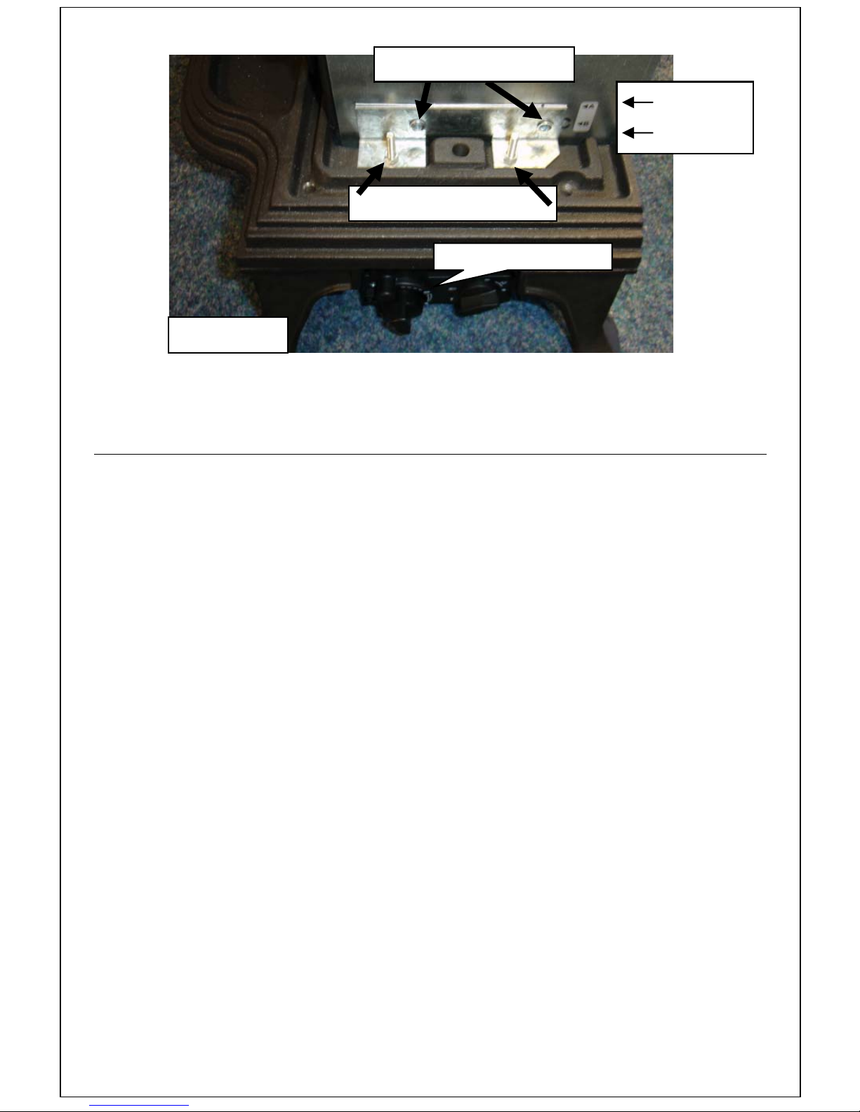
P1 - self tapping screws
P2 - bolts & washers
FIGURE 16
6 Once the Balanced flue gas fire assembly is bolted to the base casting (as shown
above), the next stage is to prepare the fireplace, ready for the installation of this
‘sub assembly’.
3.9.3 Preparing the Installation
General Notes
1. Please attempt to keep the hole sizes for
the flue ducts as close as possible to the
minimum dimensions, shown in Figure
17 below. This will keep the installation
tidy, reducing the need for excessive use
of sealant afterwards.
2. Ensure any damp course, electrical
wiring, or any pipe work within the wall,
is not going to be affected by the
installation.
Position A
Position B
REMOTE CONTROL VALVE
3. Any gas pipe concealed in the wall, floor
or cavity must be continuous and
enclosed within a gas tight sleeve. (Gas
Safety (Installation & Use) Regulations:
1998).
4. Ensure that the chosen position for the
appliance will comply with the
requirements detailed in Section 3.5
5.
3.9.4. Installation Procedure for Non Combustible Walls.
1. Place the appliance in position with the
spacer bracket touching the ‘non
combustible wall’ immediately behind
the appliance. Using the leg adjusting
screws, adjust the individual leg heights
to level the appliance.
2. Mark the wall for the centres of the two
flue ducts. Lift the appliance clear, ready
for the drilling operation.
3. Drill the two Ø125mm holes for the flue
ducts in the previously marked positions
and drill and plug the four holes for the
wall plate fixings. Ensure that any cavity
wall insulation, or other combustible
materials within the installation, are
removed and replaced with Rockwool®
or equivalent material, to the correct
thickness.
4. Replace the appliance back in position.
Page 21
Page 26

1. Take the flue ducts supplied and push
them through the wall, onto the flue duct
spigots that are mounted on the rear of
7. Take the Air Box assembly and unscrew
the painted outer cover and terminal
from the wall plate.
the appliance. Make sure they are fully
pushed home. With the appliance
spaced correctly against the wall (using
the spacer supplied) inside the property,
go outside and mark both flue ducts at
10mm away from the external wall
surface. (Note; Two 440mm lengths of
Ø100mm tube are supplied as standard.
This is sufficient for most inset
8. Engage th e flue ducts from the a ppliance
into the wall plate.
9. Mark the four fixing positions for fixing
the wall plate in position onto the wall
and remove the wall plate. Drill and plug
the marked positions. The diagram
above shows the dimensions of the wall
plate.
installations. Longer lengths of flue duct,
up to 1000mm can be supplied. This is
also the maximum length of flue duct that
10. Apply fire cement around the two duct
spigots on the inside of the wall plate.
is permitted to be used.)
11. Engage the duct spigots with the two
2. Withdraw both flue ducts and cut them
squarely at the mark made in the above
paragraph (10mm away from the
external wall surface)
3. Deburr the ends of the tube.
tubes from the rear of the appliance. The
duct spigot on the outside of the wall
plate must be uppermost.
12. Screw the outer cover and terminal back
onto the wall plate. Apply a bead of
mastic around the periphery of the wall
4. Paint any exposed are a of the upper flue
plate to prevent water ingress.
duct with black, high temperature paint.
13. If the centre of the terminal is within 2
5. Apply fire cement around each of the
flue duct spigots on the rear of the
metres of the ground or a balcony the
terminal guard (supplied) must be fitted.
appliance.
14. Push the wall plate fully home and fix in
6. Push the two lengths of flue duct through
position with appropriate screws.
the wall and onto the duct spigots on the
rear of the appliance. Make sure the
tubes are pushed fully home, right up to
the firebox. Turning them clockwise will
15. Fill the gaps between the flue ducts and
the wall with mineral wool, Rockwool® or
equivalent material.
assist this.
Page 22
Page 27
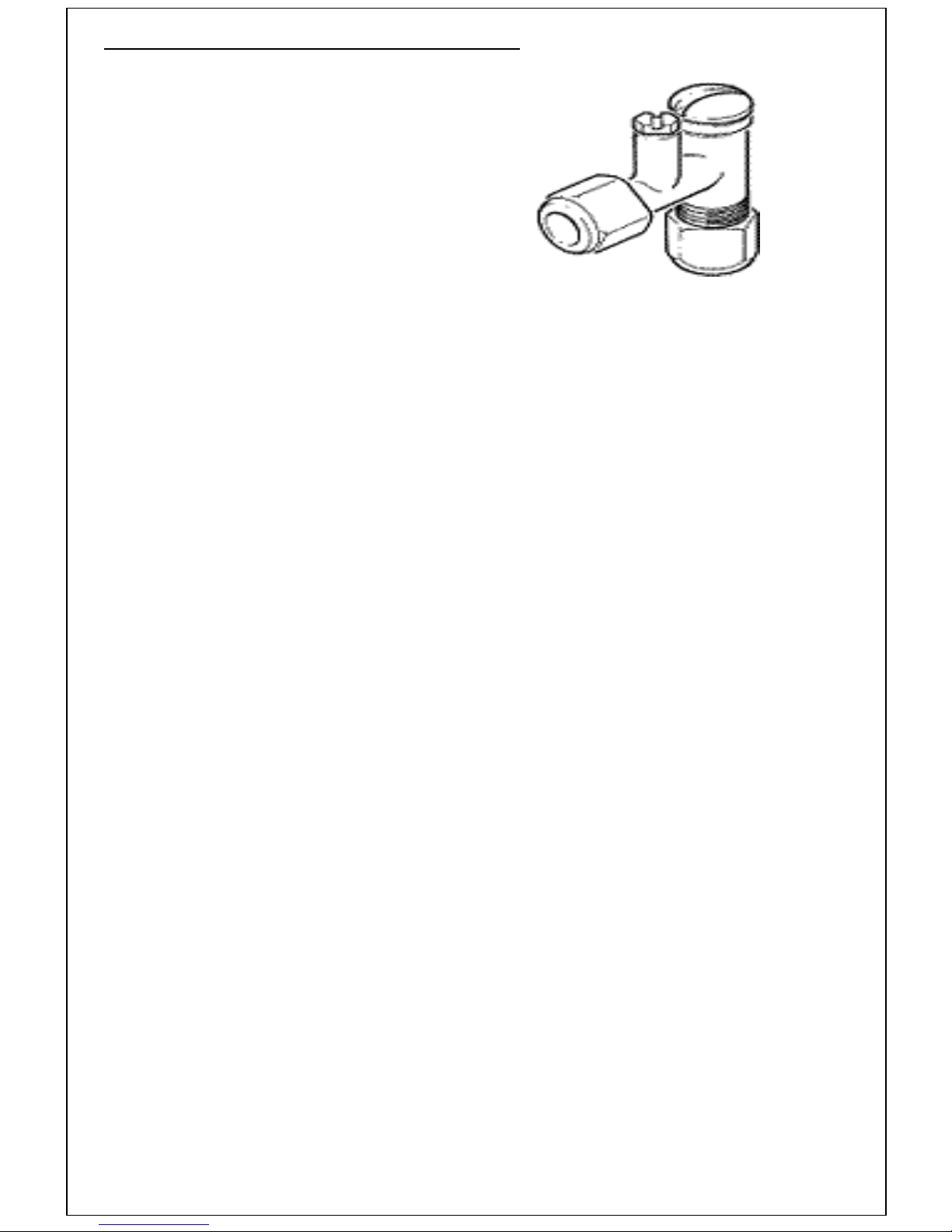
3.9.5 The Gas Supply
1. The gas supply can be fed to the
appliance from underneath. Care should
be taken to sleeve the pipe when
passing through masonry.
2. An 8mm isolating valve (with a pressure
test point) has been supplied with this
fire to facilitate isolation of the fire during
servicing.
3. The gas supply to the fire must be
carried out using rigid or semi-rigid
tubing.
4. Connect the outlet of the isolating valve
to the inlet of the control valve on the fire
tray. The outlet on the isolating valve is
the one nearest to the pressure test
point.
FIGURE18
ISOLATING VALVE WITH TEST POINT
5. Once the gas connection has been
completed, follow the instructions for the
correct positioning of the logs or coals, in
Fuel Effects Layout section. (next page.)
Page 23
Page 28
3.9.6 Fuel Effects Layout
It is recommended that the imitation fuel be left alone once the desired flame pattern has been
achieved. Constant moving of the imitation fuel will cause the fuel to disintegrate and/or
cause discolouration.
Due to the nature of this appliance, any ‘work’ regarding the Fuel effect
layout should only be carried out by a Gas Safe Registered Installer
Refractory Ceramic Fibres (RCF) advice:
This product may use Components (Fuel Effects & Ceramic backs) containing
Refractory Ceramic Fibres (RCF), which are man-made, vitreous silicate fibres.
Excessive exposure to this material may cause irritation to eyes, skin and
respiratory tract.
Therefore, during installation and servicing, we recommend that you use a HEPA
filtered vacuum to remove any dust and soot accumulated in and around the fire
before and after working on the fire. This is to ensure that the release of fibres
from these RCF articles is kept to a minimum.
We recommend that you should follow the normal hygiene rules of not smoking,
eating or drinking in the work area.
When replacing Components containing Refractory Ceramic Fibres (RCF), we
recommend that the replaced items are not broken up, but are sealed within
heavy duty polythene bags and clearly labelled as RCF waste. RCF waste may
be disposed of in suitably licensed landfill sites.
WARNING: Do not touch the fire when it is alight. The fire will remain very hot for
a while after extinguishing, as will the artificial coals and logs.
Page 24
Page 29
3.9.7 Coal Effect Layout
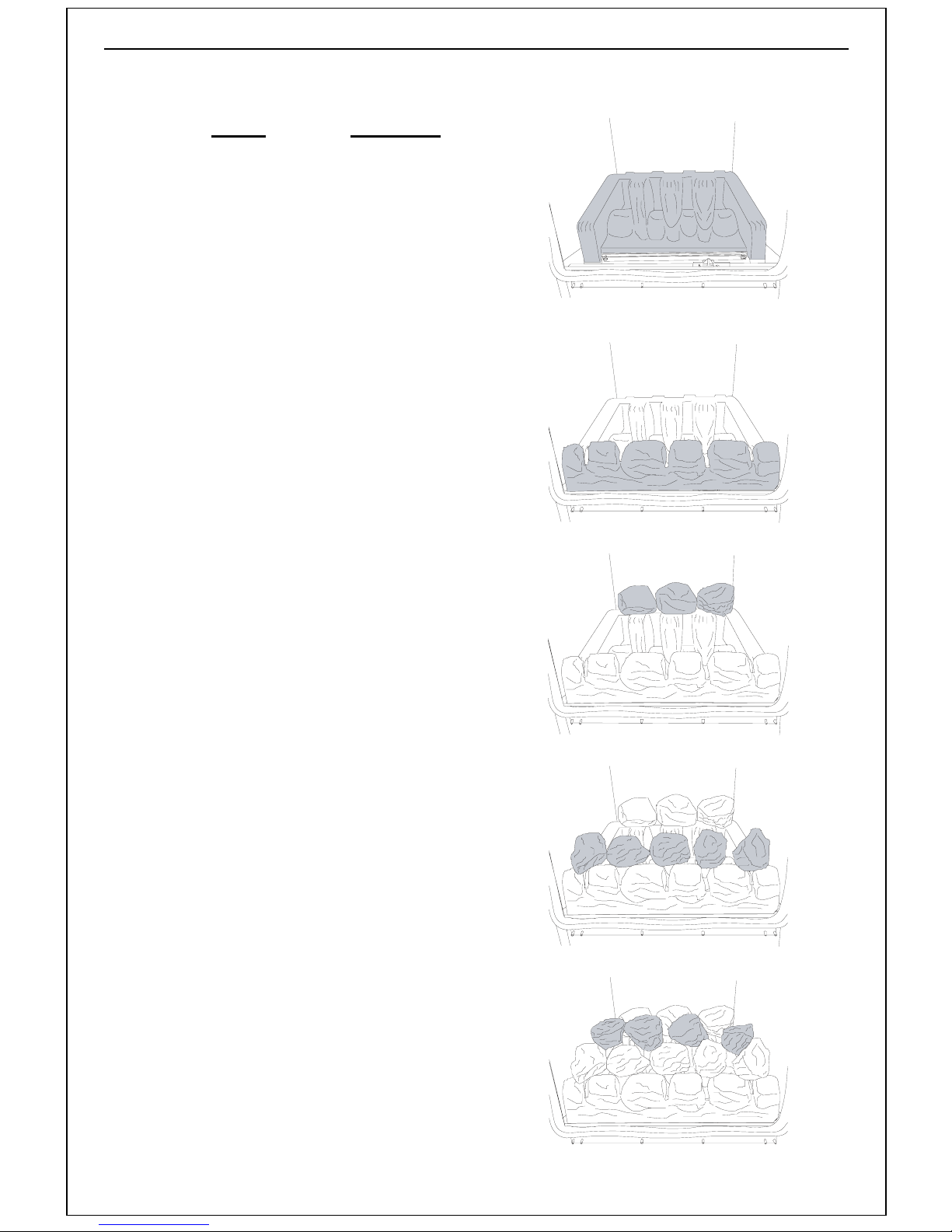
The COAL SET comprises of the following:
PART
QUANTITY
Front Ceramic 1
Rear Ceramic 1
Ceramic Coals 12
Ensure that the flat faces of the coals are
facing down, or into the fire, and there are
enough gaps between the coals.
Proceed with the layout as follows:
1. Position the rear burner ceramic in
position, behind the rear burner flange,
as shown in Figure .
2. Gently lift the rear ceramic so that the
front ceramic slides in easily. Place the
front burner ceramic in its support, in
front of the burner, as in FIGURE 20.
3. Place three coals across the top of the
rear ceramic, as shown in Figure .
Ensure that the flat faces of the coals are
facing downwards, into the fire. These
coals should touch each other, and the
rear face of the firebox.
Figure 19 – Rear Ceramic
Figure 20 – Front Ceramic
4. Place five coals across the front of the
fire. These coals should rest partly on
the front ceramic (in the shallow cut outs)
and partly on the protrusions from the
base of the rear ceramic. The furthest
left hand coal, and the two furthest right
hand coals should be angled front to
back. The other two coals should be
angled across the fire, left to right.
(see Figure).
5. Place four coals bridged between the
rear and the front coals (see Figure ).
6. Ensure that the flat faces of the coals are
facing downwards, into the fire.
It is recommended that the fuel effect be left
alone once the correct positioning and
desired flame picture has been achieved.
Constant moving of the fuel eff ect causes
the fuel effect to disintegrate and/or
cause discolouration.
Figure 21 – Rear Coals
Figure 22 - Front Coals
Figure 23 – Top Coals
Page 25
Page 30
3.9.8 Log Effect Layout
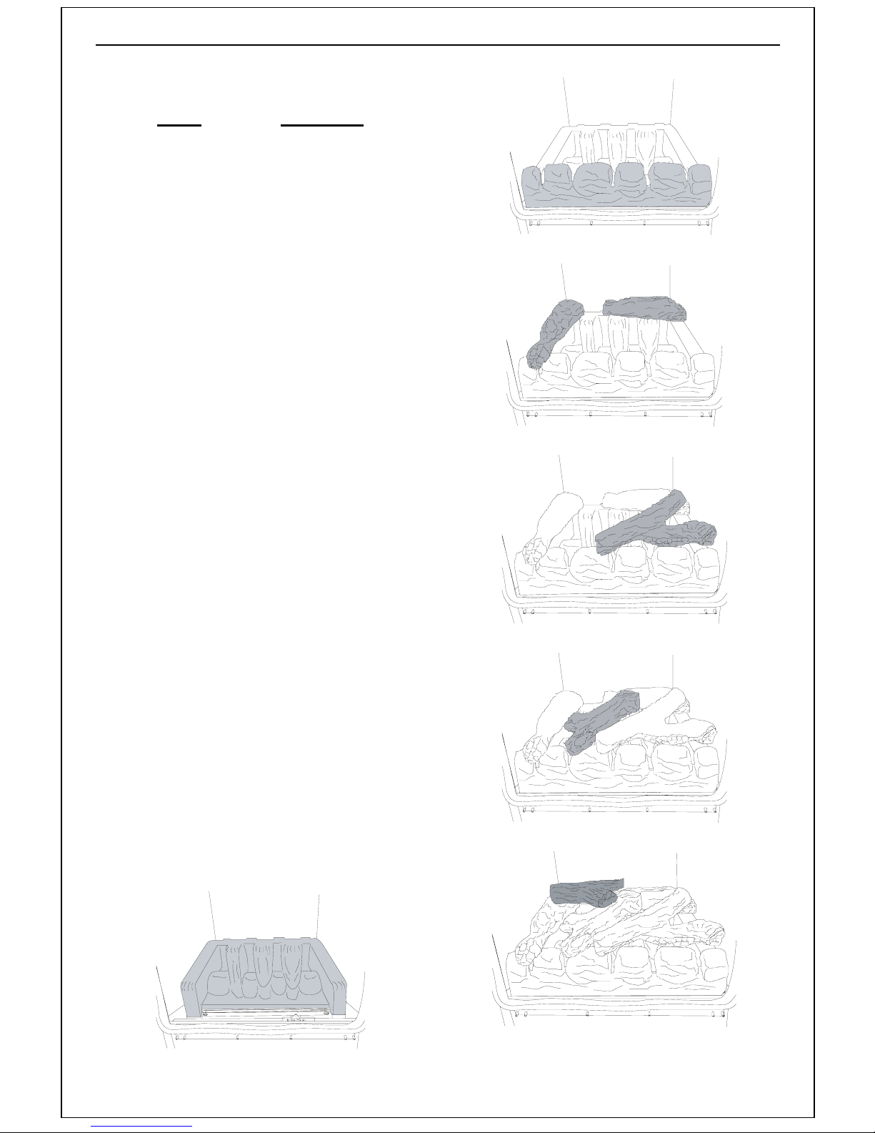
The LOG SET comprises of the following:
PART
QUANTITY
Rear Ceramic 1
Front Ceramic 1
Straight Logs 2
Large ‘Y’ Log 1
Small ‘Y’ Log 1
Stubby ‘Y’ Log 1
Proceed with the layout as follows:
1. Position the rear burner ceramic behind
the rear burner flange, see Figure 24
2. Place the front burner ceramic in its
supports in front of the burner as in
Figure 25. Manipulate the rear ceramic
so that the front ceramic slides in easily.
3. Place one straight log on the rear
ceramic, across the rear right hand side,
with the burnt end facing right. Place the
other straight log on the left hand side,
with the burnt end facing front, bridging
between the front and rear ceramic (see
Figure )
4. Place the large ‘Y’ log across the front
ceramic with one of the legs of the ‘Y’
resting on the straight log at the back
(see Figure 14).
5. Proceed with placing the small ‘Y’ log,
bridging between the front and rear
ceramic and behind the front ‘Y’ log, as
in Figure 15.
6. Finally place the stubby ‘Y’ log in the
left hand rear corner (see Figure 16).
7. It is recommended that the fuel effect be
left alone once the desired flame picture
has been achieved. Constant moving
of the fuel effect causes the f ue l eff ect
to disintegrate and/or cause
discolouration.
Figure 25
Figure 26
Figure 14
Figure 15
Figure 24
Page 26
Figure 16
Page 31
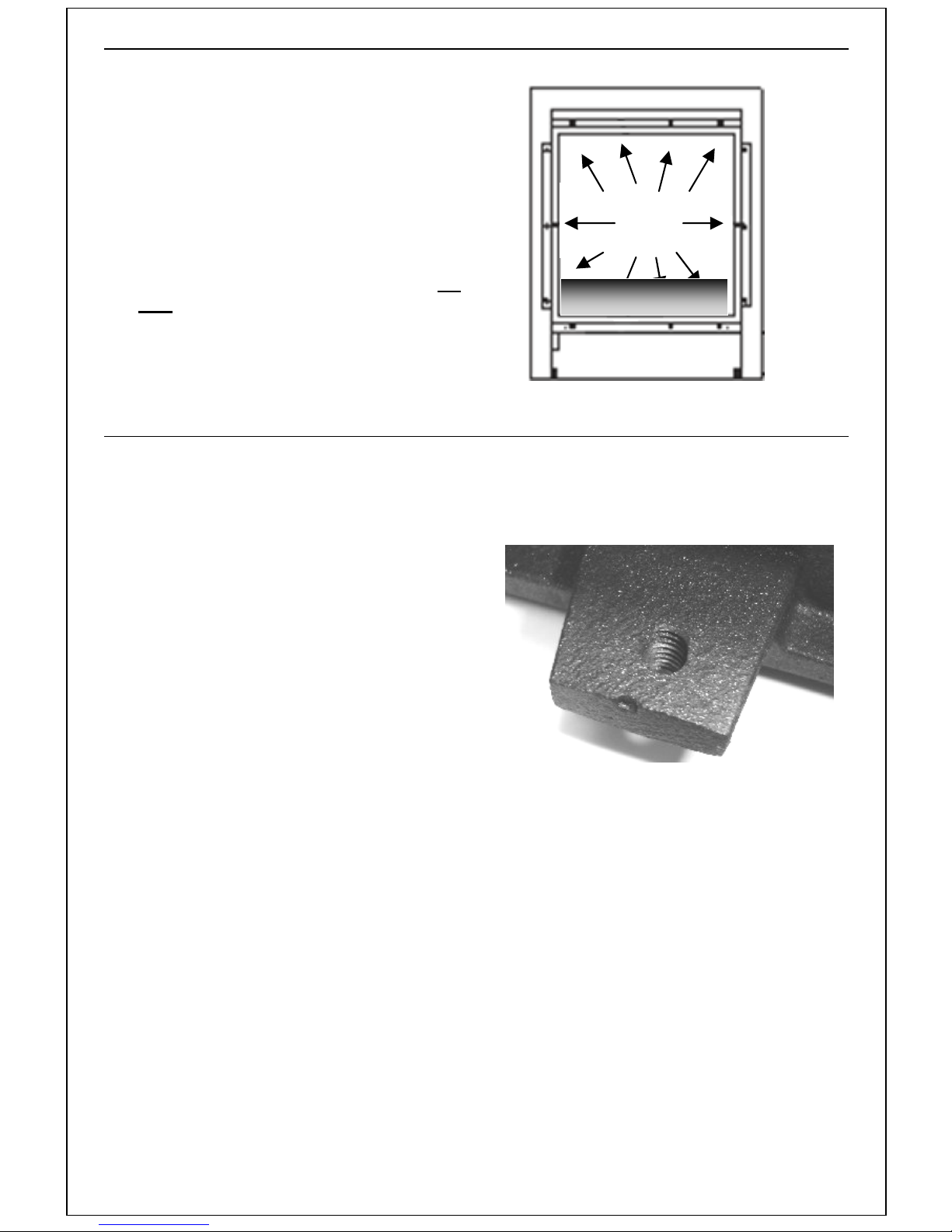
3.9.9 Fitting the Glass Panel and frame
Rti
i
1. Refit the glass panel/frame to the front of
the appliance, taking care not to move
any of the ceramic logs or coals. Secure
glass in position using the previously
removed nuts. (see FIGURE 30)
2. To ensure a goo d seal tighten the nuts in
a diagonal sequence a few turns at a
Retaining
nuts
time.
3. Fully tighten all the retaining nuts. Do
use power tools to tighten the nuts.
Not
4. Do not over-tighten the nuts and ensure
that the seal behind the frame is gas
tight.
FIGURE.30GLASSFRAMERETAININGNUTS
3.9.10 Assembling the Cast Iron Stove Components.
Now the burner sub assembly has been
installed as the ‘gas fire’, the final
decorative casting can be fitted to the
installed appliance. Please read the step
by step instructions below.
5. Carefully lift and locate the side a nd front
castings, as one assembly, to the base
casting. This is a snug assembly and
care should be taken not to rush this
procedure. Once the side and front
casting assembly is located squarely to
the base casting, secure it using the 2off
bolts and washers provided. These
locate from underneath, through the
clearance hole in the base casting, and
screw into the threaded tongue on the
bottom of each side panel. See figure 31.
6. The clearance hole in the base casting
can be seen in the Figure 16, (on page
18)
7. Locate the lid squarely onto the stove
body. The lid should locate onto the top
of the stove but does not need to be
fixed in position.
FIGURE 31. SIDE CASTING, THREADED TONGUE.
Page 27
Page 32
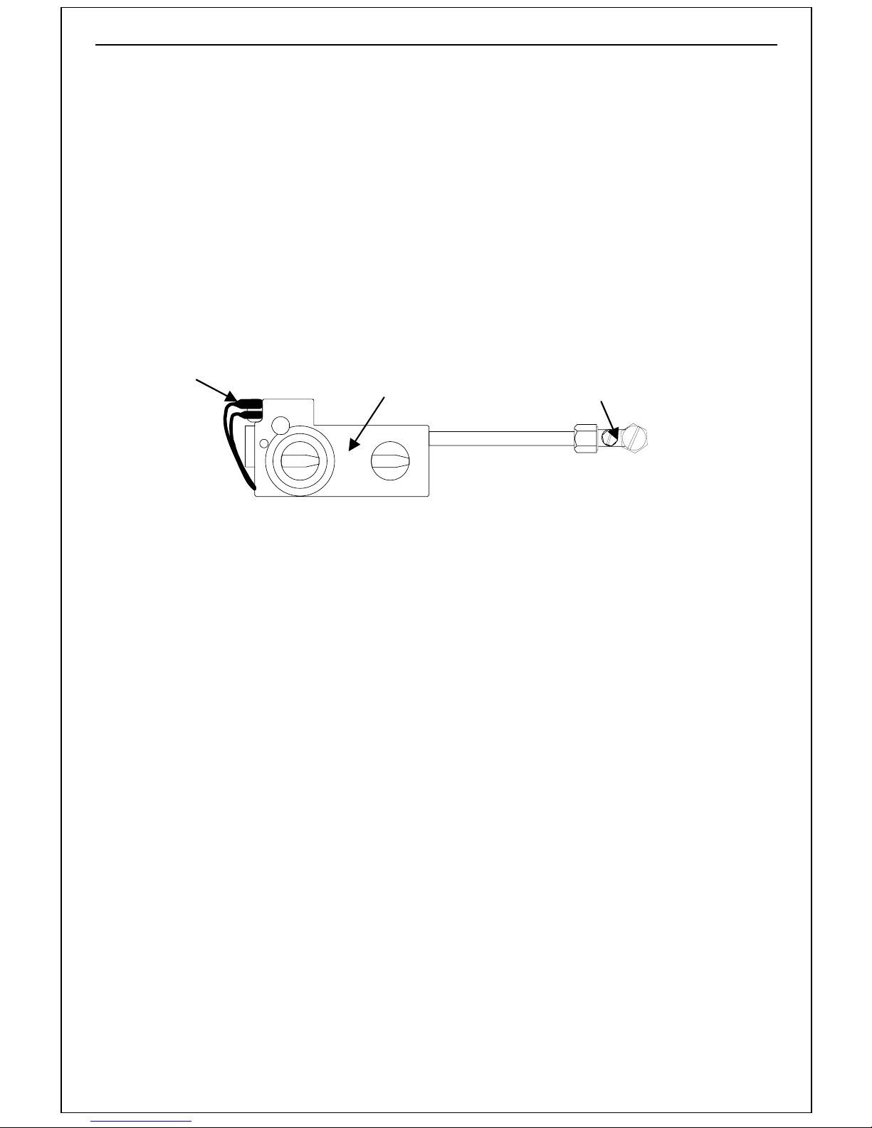
3.9.11 Continuation of Installation - Remote Control
S
1. Unpack the box containing the Receiver
and the Hand Set.
2. Fit four AA (1.5V) batteries into the
receiver unit and one PP3 (9V) battery
into the hand set (transmitter)
3. Feed the cable from the receiver unit to
the spade terminals on the control valve
motor. Keep the cable clear of the
underside of the combustion chamber,
failure to do so may cause heat damage
to the cable. The cable connectors must
SPADE CONNECTIONS
+
CONTROL VALVE
be matched to the appropriately sized
spade connector, one large, one small.
(see Figure 32).
4. This ensures the correct rotation of the
motor when the up or down button is
pressed on the handset.
5. Test the operation of the drive motor
using the hand set as per Users
Instructions Section 2.2.2 Lighting
procedure (Remote Control)
ISOLATING VALVE WITH
T POINT
TE
FIGURE 32 CONTROL & ISOLATING VALVE
Page 28
Page 33

3.9.12 Commissioning
1. Turn on the gas supply to the fire and
purge the gas line. Check all the gas
joints for gas soundness.
2. Connect a pressure gauge to the
pressure test point on the isolating valve.
3. Ignite the pilot in accordance with the
User Instructions.
4. Set the controls to give full gas rate at
the main burner. Check that the main
burner cross lights smoothly.
5. Ensure that the pressure at the pressure
test point is 20 ±1.0mbar for natural gas.
6. If the correct pressure cannot be
achieved, then some potential causes of
low pressure are:
a) Supply pipes are not of large
enough diameter.
b) The supply pipes are kinked,
blocked or partially blocked.
c) Restriction at the appliance
isolation valve.
7. Set the control to the low rate position
(small flame image) and ensure that the
flames reduce in size.
8. Turn the fire off.
9. Replace the screw in the pressure test
point.
Page 29
Page 34
3.9.13 Instructing the User
The installer must hand over these
instructions to the user and explain how to
operate this fire, stressing the importance of
having the fire checked and serviced
regularly. An annual service is
recommended.
It is mandatory as part of the
gas installation that the installer
instructs the user on the correct
operation and care of their
appliance.
Page 30
Page 35
4 SERVICING INSTRUCTIONS
4.1 General Requirements
All repairs and servicing must be carried out by a qualified registered gas installer (e.g.
member of Gas Safe Register in GB) in accordance with the current Gas Safety (Installation
and Use) Regulations and these instructions.
Before any servicing is carried out ensure that the gas supply is turned off.
Always check for gas soundness after dismantling or exchange procedures.
CAUTION: Ensure that the appliance is off (including the pilot light) and has
completely cooled (off for at least 2 hours) before carrying out any cleaning or
maintenance.
RCF Advice:
This product may use Components (Coals, Pebbles & Ceramic backs)
containing Refractory Ceramic Fibres (RCF), which are man-made vitreous
silicate fibres. Excessive exposure to this material may cause irritation to eyes,
skin and respiratory tract.
Therefore during installation and servicing we recommend that you use a HEPA
filtered vacuum to remove any dust and soot accumulated in and around the fire
before and after working on the fire, to ensure that the release of fibres from
these RCF articles is kept to a minimum.
We recommend that you should follow the normal hygiene rules of not smoking,
eating or drinking in the work area.
When replacing Components containing Refractory Ceramic Fibres (RCF), we
recommend that the replaced items are not broken up, but are sealed within
heavy duty polythene bags, and clearly labelled as RCF waste. R CF waste may
be disposed of in suitably licensed landfill sites.
Most servicing operations on this appliance will require the cast iron stove body panels to
be removed. Refer to the appropriate section for details of how this is done.
Page 31
Page 36
4.1.1 Cleaning the Fuel Effect, Fire-bed and Combustion Chamber
1. Remove the cast iron top, sides and
front of the stove.
2. Remove the glass door pa nel and place
it in a safe place.
3. Carefully remove all the fuel bed
ceramics from the fire. Lift out the front
and rear ceramics. Any debris/dust or
soot can be brushed off using a soft
brush.
4. Remove the two screws securing the
burner and gently lift it out of the
appliance. Clean the burner slot with a
brush and check that the venturi is
clear.
5. Check that the electrode sparks across
the gap when the ignition knob is
operated.
4.1.2 Cleaning Lining Board Panels
6. Use a vacuum cleaner to remove any
fluff or lint on the base of the
combustion chamber.
7. Refit the burner and secure in place
using the previously removed screws.
8. Replace the front and rear ceramics
and relay the fuel bed as described in
the appropriate fuel bed layout sections.
9. Refit the glass/frame and secure in
place using the previously removed
nuts. Refit the infill plate.
10. The flue can be inspected and cleaned
by removing the terminal/ outer cover.
11. Re-assemble the cast iron sides, front
and top of the stove.
Any soot or dust marks on the side, top or rear panels can be cleaned by lighting dusting
them with a very soft brush.
NOTE: Any attempt to clean the lining panels using an alternative method, will
result in irreparable damage leading to a replacement being required.
4.1.3 Care of Lining Panels
The lining panels on this appliance must NOT be sprayed with any type of solvent-based high
temperature paint.
The very high temperatures produced within the appliance will cause the paint to bubble
and/or burn off rendering the fireback looking unsightly.
Minor surface scuffs may be treated using a water based touch up stain available at Magiglo
fire retailers.
Extreme care should be taken when handling and installing products containing
ceramic fibre board, so as not to cause damage.
Page 32
Page 37
4.2 Replacing Parts
t
For any spare parts that are required, please contact either your supplier or the m anufacturer
directly. You will need the model name i.e. model number, the gas type, the type of control
and serial number. Servicing and repairs to your appliance must be carried out b y a Gas Safe
engineer.
Only approved parts must be used. Isolation of the appliance from the gas supply will
be necessary, before any ‘work’ is carried out.
4.2.1 Burner Components Removal and Replacement
For ease of access to all the burner
components, we recommend removal of
the entire burner assembly from the
decorative cast iron stove surround.
Please inspect the condition of any seals
or spacers before re-assembly and
replace if necessary.
Section 3.9 describes the installation
procedure of the burner assembly into
the decorative cast iron stove surround.
Reverse this procedure till you have
easy access to the component you wish
to service or replace.
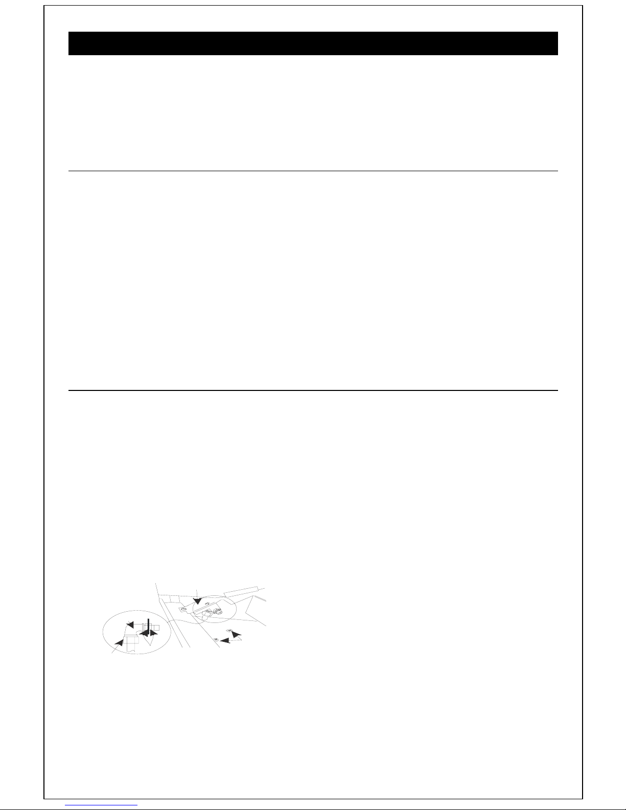
4.2.2 Injector Replacement
1. Remove the cast iron top, sides and front
of the stove.
2. Remove the glass door panel, the fuel
bed components and the front and rear
ceramics.
3. Lift out the top lining board, followed by
the two sides and the back.
4. Remove the main burner. See FIG. 31
5. Grip the injector nose whilst undoing the
injector tube nut.
Injector
Injector tube
nut
Burner support
bracket
Securing
Nuts
Valve Bracke
fixing screws
NOTE: If at any time the pilot assembly
is removed or replaced, the spacer
should be replaced as well.
6. Unscrew the outer injector securing nut.
Unscrew the self tapping screws,
holding the burner support bracket in
place. Lift away the support bracket.
7. Remove the injector and replace it with
the new one. Change over the rear
securing nut.
8. Replace the burner support bracket and
secure with the four self tapping screws.
Replace the outer injector securing nut
and tighten. Grip the injector nose and
tighten the tube nut, making sure that the
injector is correctly aligned.
9. Replace all the other components.
FIGURE 30. INJECTOR & VALVE DETAIL
Page 33
Page 38
4.2.3 Control Valve Replacement (Manual Control /Remote Control)
)
For ease of access to all the burner
components, we recommend removal of the
entire burner assembly from the decorative
cast iron stove surround.
Please inspect the condition of any seals or
spacers before re-assembly and replace if
necessary.
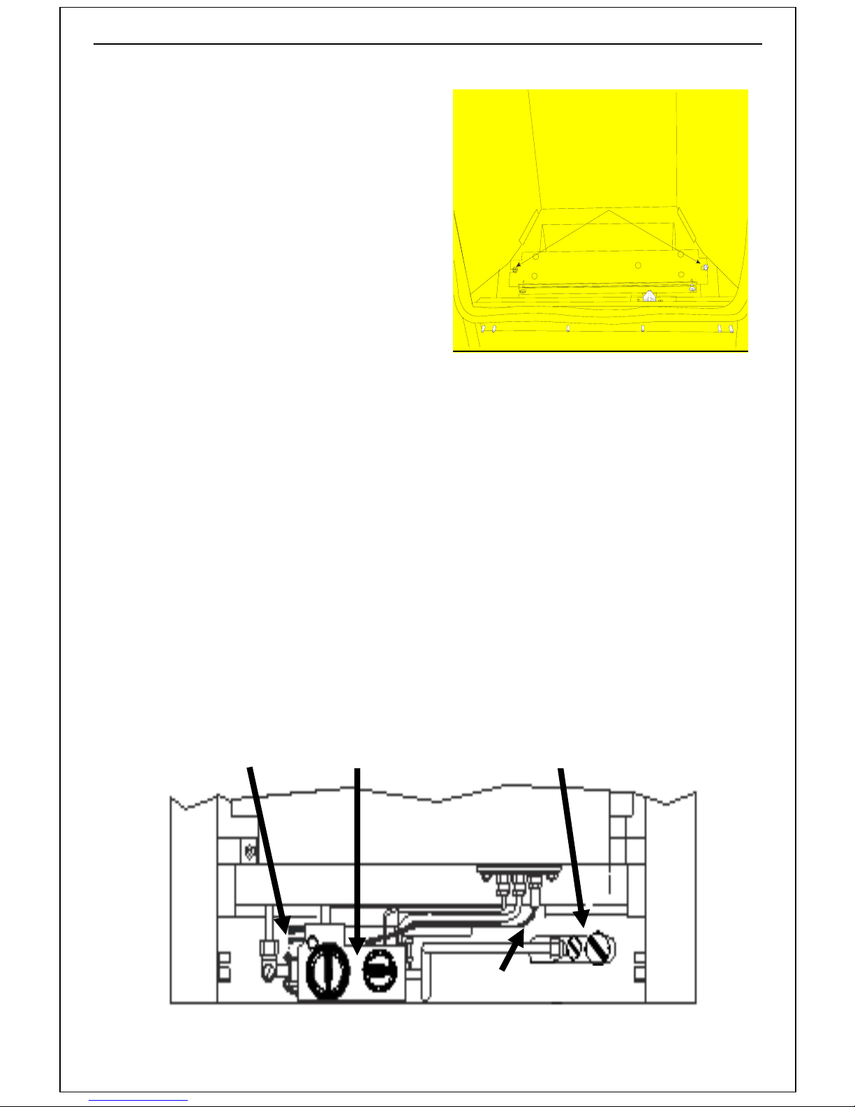
1. Once the burner assembly is safely
removed, remove the spark lead from
the electrode on the pilot burner.
2. Remove the 4off spade connections from
the motor. The receiver is connected to
the other end, located on the hearth,
under the appliance.
FIGURE 31 BURNER SECURING SCREWS
3. Disconnect the thermocouple from the
rear of the valve. Unscrew the gas
connections from the valve.
4. Remove the old valve from the mounting
bracket and replace with new one. If
necessary, remove the tube adaptors
from the old valve and fit them to the
7. Transfer all the tubing on the old valve to
the new one, ensuring that the tubing
positions are the same as before.
Tighten all connections.
8. Refit the rest of the components in
reverse order.
new valve.
9. Reconnect the thermocouple to the rear
5. Remake the gas connections.
6. Remove the valve cover by removing the
securing screw and levering out the
of the valve, taking care not to kink the
pipe.
10. Refit the valve in reverse order.
cover through the slot on the opposite
side using a small screw driver.
11. Refit the HT lead and remake all the gas
connections.
SPADE
CONNECTIONS
CONTROL
VALVE
ISOLATING VALVE
WITH TEST POINT
PILOT
ASSEMBLY
SPARK LEAD (HT
FIGURE 32. REMOTE CONTROL & ISOLATING VALVE
Burner Securing
Screws
Page 34
Page 39
4.2.4 Motor Replacement (Remote Control Model)
For ease of access to all the burner
components, we recommend removal of the
entire burner assembly from the decorative
cast iron stove surround.
Please inspect the condition of any seals or
spacers before re-assembly and replace if
necessary.
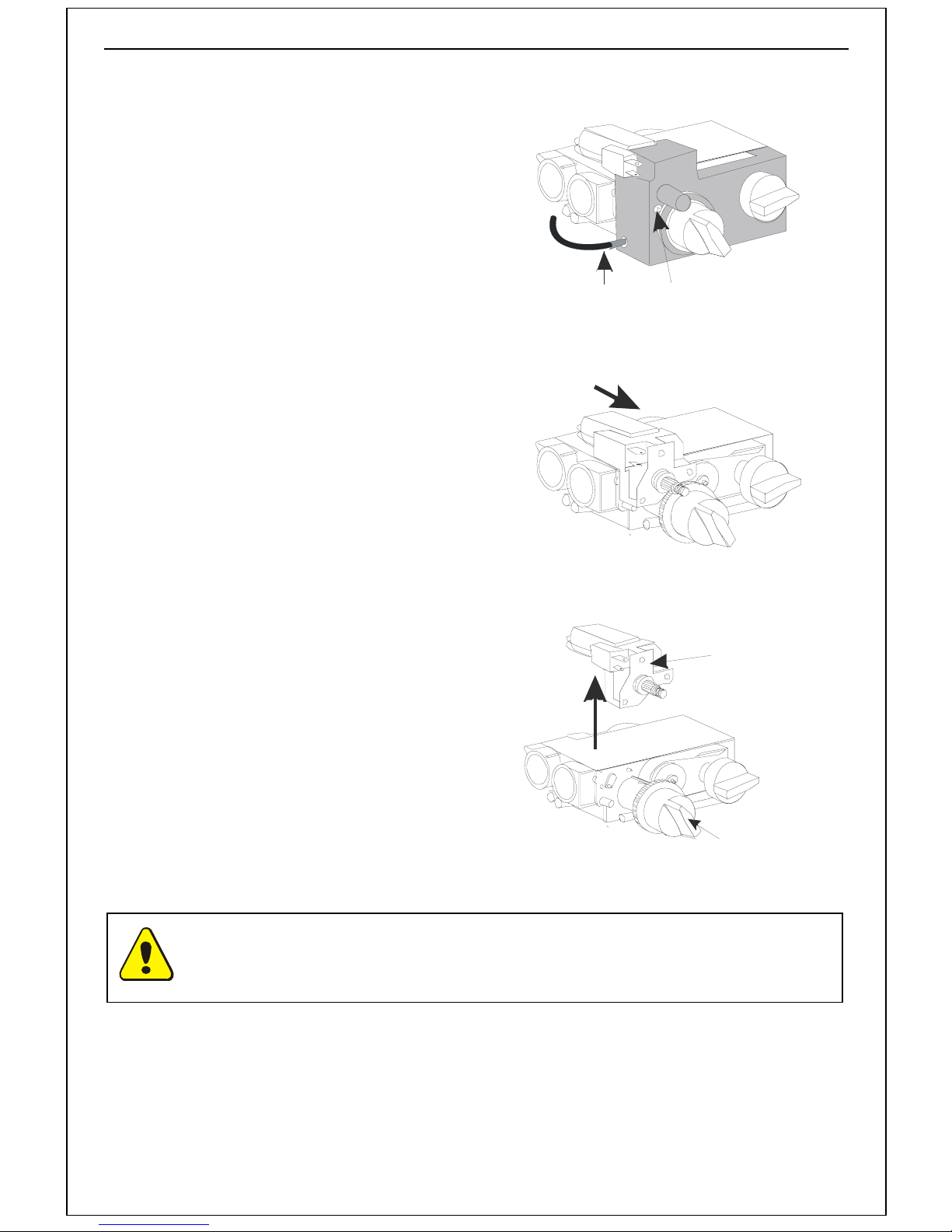
1. Remove the batteries from the receiver
unit to prevent the risk of short circuit.
2. Remove the two motor connection tags
from the valve.
3. Remove the valve cover securing screw.
4. Unclip the valve cover from the valve on
the right hand side by inserting a very
small screwdriver in the slot on the right
hand front of the cover and pull out the
cover.
5. Turn the gas rate adjusting knob fully
anticlockwise and gently manipulate the
motor free from the valve (see note).
6. Replace with new motor ensuring that
the motor is hooked into the right hand
lug.
7. Replace the cover and secure with the
screw.
HT
Lead
FIGURE 17. REMOTE CONTROL VALVE
Valve Cover
Securing
Screw
FIGURE 18
Drive
Motor
8. Remake the motor connections ensuring
that the large tag is fitted to the large
spade (top connection) and vice versa.
9. Replace the batteries ensuring the
correct polarity.
10. Operate the handset to check the
FIGURE 19
Gas Rate Adjusting
Knob
operation of the motor.
Note: Operating the gas rate adjusting knob manually will cause the motor clutch
to operate. This is normal and will not affect the valves’ operation.
Page 35
Page 40
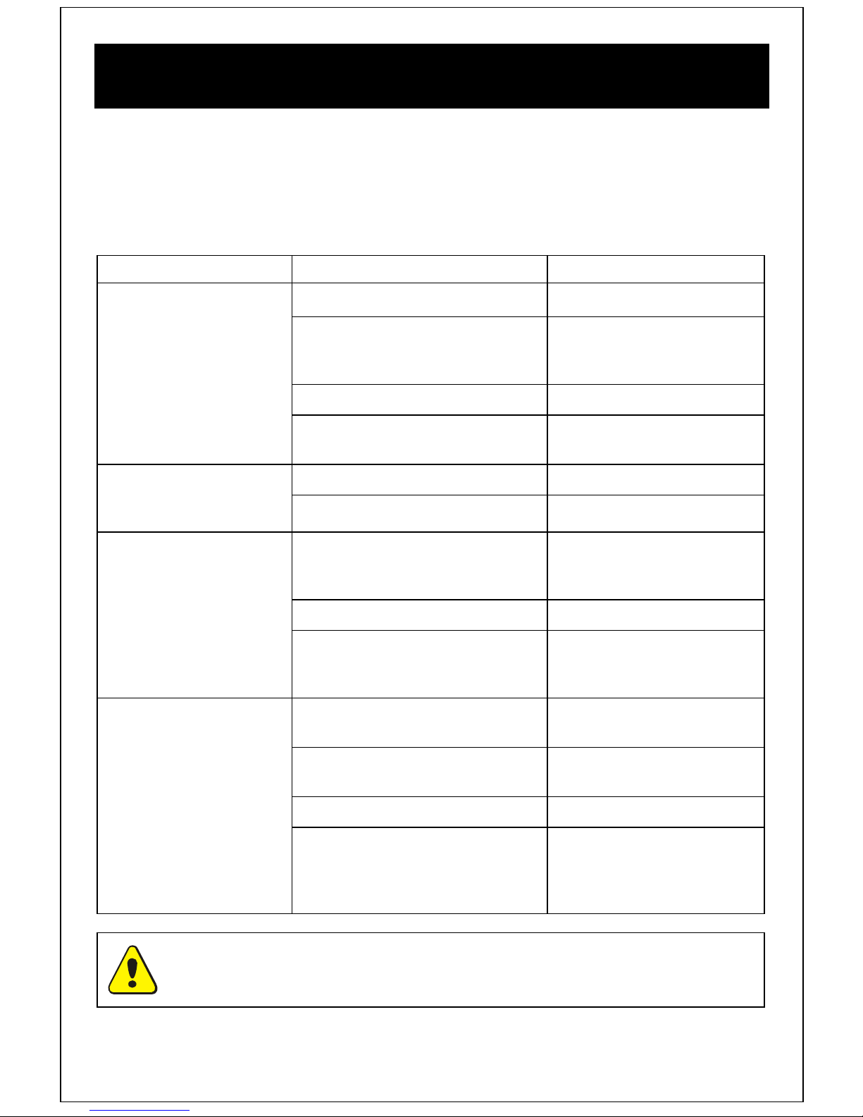
4.3 Installation and Operational
Troubleshooting
The table below is intended for problems related to the fire and its gas controls. It is a guide
only and does not take into account every eventuality. Servicing must be carried out in
accordance with the current Gas Safety (Installation and Use) Regulations, by a competent
person.
It is recommended that the purchaser seek the advice of the original installer in case of
encountering any problems.
Symptom Cause Remedy
No spark appears at
the electrode
Piezo operates
normally but pilot will
not light
Pilot lights, but goes
out when control is
released
a) Electrode cracked or broken Replace electrode
b) HT lead shorting out Establish where spark is
occurring and insulate or re-
route lead accordingly.
c) Faulty spark generator Replace valve
d) HT lead disconnected from
electrode
a) No gas supply Check isolation valve/supply
b) Pilot jet blocked Clean pilot jet
a) Loose thermocouple
connection at control valve
end
b) Faulty Thermocouple Replace thermocouple
d) Thermocouple not fully
inserted into pilot burner
Re-connect HT lead to
electrode
Remake thermocouple
ensuring the connection is
firm
Loosen thermocouple clamp
nut and push thermocouple
fully upwards
Pilot and main burner
go out when control is
set to high position
Warning: If you are in any doubt about the clearance of fumes, you must stop
using the appliance immediately and seek expert advice. Do not use appliance
until the fault has been rectified.
Page 36
a) Gas supply partially blocked
b) Too many bends on gas inlet
pipe
c) Pilot jet partially blocked Clean pilot jet.
d) Restriction at Isolation valve Ensure valve is fully open
Locate restrict and remove
faulty section
Increase diameter and/or
reduce the number of bends
and that internal diameter is
sufficient and free from
grease
Page 41
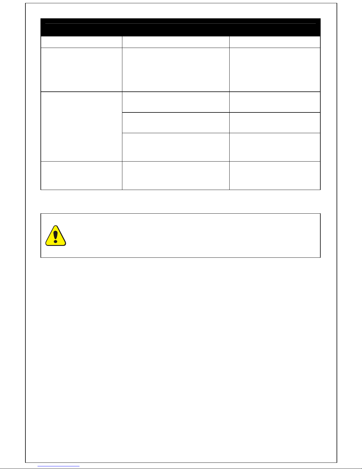
Remote Control
Symptom Cause Remedy
Main burner will not
come on when
required even though
the drive motor is
heard to be operating
Motor not functioning
when buttons are
pressed
Remote Control will
turn fire off but will
not turn on
NOTE: For any spare parts that are required, please contact either your supplier
or the manufacturer directly. You will need the model name i.e. Model Number,
the gas type, the type of control and serial number.
Only approved parts should be used.
Ignition knob incorrectly set Set the ignition knob at the
9 o’clock position.
a) Flat hand set battery
(Remote Control)
b) Flat batteries in receiver
unit (Remote Control)
c) Flat batteries in battery
holder (Trim Switch and
Optimum Control)
Incorrect hand set operation Ensure two buttons are
Replace battery (1 X PP3)
Replace all 4 AA batteries
Replace all 4 AA batteries
pressed to turn on
Page 37
Page 42

Guarantee
Dear Customer,
Your gas appliance, when installed in accordance with the installation instructions and
operated in accordance with these instructions, should provide many years of safe and
efficient operation.
We thank you for purchasing our product and trust it will provide excellent service.
This appliance carries a guarantee of 1 year. The consumable components of this appliance
are guaranteed for one year.
We agree to repair free of charge or, at our option, replace the appliance or part thereof, which
may prove to be defective within the guarantee period.
In the unlikely event of a defect in materials or workmanship occurring within one year of
purchase, please contact the shop from where the appliance was purchased.
Any claims under this warranty must be made through the retailer from whom the product
was purchased.
The purchaser’s contract of sale is with the retailer, not Broseley Fires.
We (Broseley Fires) are unable to enter into discussions with the purchaser, until the
retailer has inspected any claim and deemed it to be valid.
Broseley Fires reserve the right to refuse service or make a charge for any service call,
when a defect is due to any of the following issues which will void your Guarantee.
The guarantee is void if:
• The appliance is not installed and operated in accordance with our instructions; or
• The appliance is not serviced, by a Gas Safe registered engineer, annually; or
• Repairs of modification have been carried out by the purchaser or any third party not
authorized by us; or
• The appliance has been misused or accidentally damaged; or
• Damage is due to ‘fair wear and tear’; or
• The appliance or defective component(s) are not returned to us, prepaid postage.
The rights given in this guarantee are limited to the UK mainland and are in addition to any to
which you may have a statutory entitlement.
Please retain your purchase receipt, we may need to see this in the event of a claim under
warranty.
Page 38
Page 43

This page is left intentionally blank
Page 39
Page 44

Contact Details:
Broseley Fires Ltd
Knights Way
Battlefield Enterprise Park
Shrewsbury
SY1 3AB
Tel: +44 (0) 1743 461444
Fax: +44 (0) 1743 461446
Email:
This product is protected by
UK patents 2193802, 2240620 and 2256920
Other Patents Pending
MFTBA
 Loading...