

Page 1
Installation & Operating
Instructions
Covering Models:
eV olution 4 & 7 Insert
Wood Burning Stoves
Tested to EN 13229
These appliances must be installed and commissioned by a HETAS registered engineer
MS11-11 Issue 3 1
Page 2

Contents
Introduction 3
Packing List 3
Health & Safety 4
Specifications 5
Dimensions 6
Hearth Requirements & Clearances 7
Chimney Requirements 8
Combustion Air Requirements 9
Assembly 10
Stove Operation
Controls Layout 15
Controls Explained 16
Air wash System 16
Ash Pan 16
Recommended Fuels 17
Lighting the Stove
Kindling Stage 18
Burning Wood 19
Smoke Exempt Requirements 20
Warning Notes 23
Maintenance
Ash Removal 24
Chimney Fires 24
Chimney Sweeping 24
General Stove Cleaning 24
Glass Cleaning 24
Annual Stove Service 24
Trouble-shooting 25
Commissioning Form 26
EC Declaration 27
Annual Service Record 29
Warranty 30
MS11-11 Issue 3 2
Page 3

Introduction
May we take this opportunity to thank you for choosing one of our stoves. These
appliances are designed to burn wood logs and wood derived fuels. It is essential that your
wood has been seasoned to ensure that it is sufficiently dry for burning. You can determine
the moisture content of your logs by using a digital moisture meter, your logs need to be
below 20% moisture content before they are considered dry enough for burning.
Never burn wood that contains paint, glue or any other chemicals
See the section “Lighting the Stove” for further details. After reading this document, if there
is anything you are unsure about, please contact your dealer or our Technical Support
Department.
These instructions cover the basic principles to ensure the satisfactory installation of the
stove, although detail may need slight modification to suit particular local site conditions. In
all cases the installation must comply with current Building Regulations, Local Authority
By-laws and other specifications or regulations as they affect the installation of the stove.
It should be noted that the Building Regulations requirements may be met by adopting the
relevant recommendations given in British Standards BS 8303, BS 6461 and BS 7566 as
an alternative means to achieve an equivalent level of performance to that obtained
following the guidance given in Approved Document J.
Please note that it is a requirement under the Broseley Fires warranty system that
the installation of the stove is carried out by a Competent Person registered with a
Government approved Competent Persons Scheme. HETAS Ltd operate such a
Scheme and a listing of their Registered Competent Persons can be found on their
website at www.hetas.co.uk
.
Packing List
eV olution 4 eVolution 7
1x Cast Iron/Steel Stove 1x Cast Iron/Steel Stove
1x Rear Firebrick 1x Rear Firebrick
1x Baffle 2x Baffles (1 Stee l 1 Vermiculite)
2x Side Firebricks 4x Side Firebricks
1x Spigot 1x Spigot
1x Grate & Ash Pan 1x Grate & Ash Pan
1x Gloves & Ash Tool 1x Gloves & Ash Tool
1x Instruction Booklet 1x Instruction Booklet
All parts will be inside the main stove body upon delivery, apart from the spigot which will
be bolted to the stove.
MS11-11 Issue 3 3
Page 4

Health & Safety
Special care must be taken when installing the stove such that the requirements of the
Health and Safety at Work Act are met.
Installation
This appliance MUST be installed and commissioned by a HETAS registered installer in
England and Wales and a fully qualified Heating Engineer in Scotland and Ireland.
Handling
Adequate facilities must be available for loading, unloading and site handling.
Fire Cement
Some types of fire cement are caustic and should not be allowed to come into contact with
the skin. In case of contact wash immediately with plenty of water.
Asbestos
This stove contains no asbestos. If there is a possibility of disturbing any asbestos in the
course of installation then please seek specialist guidance and use appropriate protective
equipment.
Metal Parts
When installing or servicing this stove care should be taken to avoid the possibility of
personal injury.
CO Alarms
Building regulations require that whenever a new or replacement fixed solid fuel or
wood/biomass appliance is installed in a dwelling an audible carbon monoxide alarm must
be fitted in the same room as the appliance. Further guidance on the installation of the
carbon monoxide alarm is available in BS EN 50292:2002 and from the alarm
manufacturer’s instructions. Provision of an alarm must not be considered a substitute for
either installing the appliance correctly or ensuring regular servicing and maintenance of
the appliance and chimney system.
Fire Guards
When using the stove in situations where children, aged and/or infirm persons are present
a fire-guard must be used to prevent accidental contact with the stove. The fire-guard
should be manufactured in accordance with BS 6539.
Aerosol Sprays
Do not use an aerosol spray on or near the stove when it is alight.
Operating Tool & Gloves
Always use the operating tool and glove provided when handling parts likely to be hot
when the stove is in use.
MS11-11 Issue 3 4
Page 5

Specifications
In the UK these stoves have been approved by HETAS Ltd as intermittent heating
appliances for burning manufactured or naturally occurring smokeless fuels and wood logs
only .
eVolution 4 eVolution 7
Heat Output: 4.2 kW 7.0 kW
Weight: 100 Kg 139 Kg
Flue Gas Mass Flow: 5.22 g/s 4.1 g/s
Flue Gas Temp: 265°C 317°C
Flue Draft Required: 12-16 pa 12-16 pa
Flue Outlet Size: 6” / 150mm 6” / 150mm
Efficiency: 75.3% 80.9%
Other fulfilled Requirements
eVolution 4 Inset
BStv of the City of Munich, the City of Ragensburg and the City of Stuttgart
LRV of Switzerland
Level 1 of the BlmSchV
Sizing the appliance
It is essential that this appliance is correctly sized for the area it is required to heat. This
should be done by carrying out a heat loss calculation for the property and taking into
consideration the client’s requirements.
European standards need to be complied to when installing this appliance.
MS11-11 Issue 3 5
Page 6
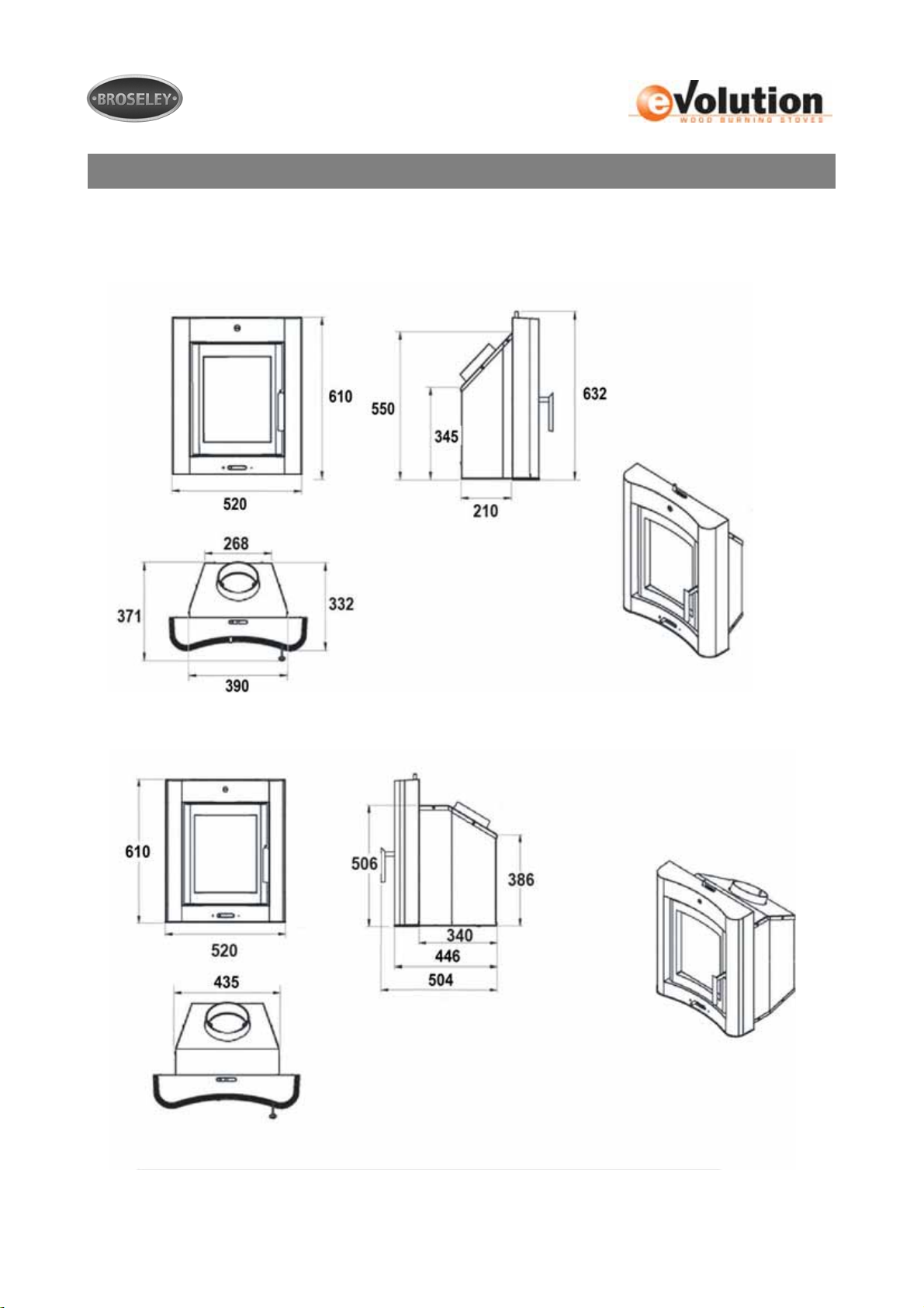
Dimensions
All dimensions are in millimetres
Evolution 4
Evolution 7
MS11-11 Issue 3 6
Page 7
Hearth Requirements & Clearances
Your stove must be installed on a solid, level non combustible hearth. The hearth
does not need to be constructional but must be at least 12mm thick. The hearth protrusion
in front of the stove to carpets or wooden floors must be at least 300mm. As it is possible
for fuel to fall out on opening the door, a fender must be fitted if the hearth is flush with the
carpet.
These are just a few hearth specifications. Please refer to Building Regulations Approved
Document J (Hearths) for more specific details.
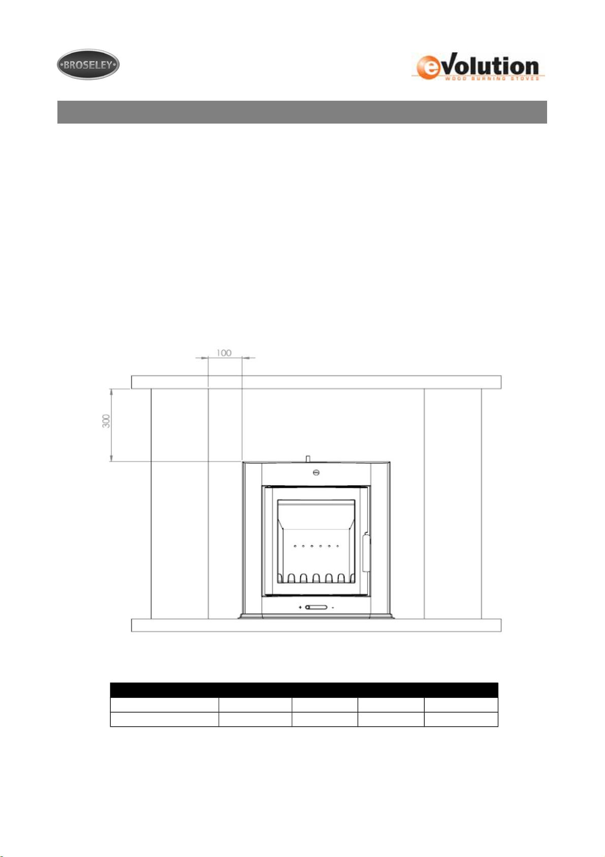
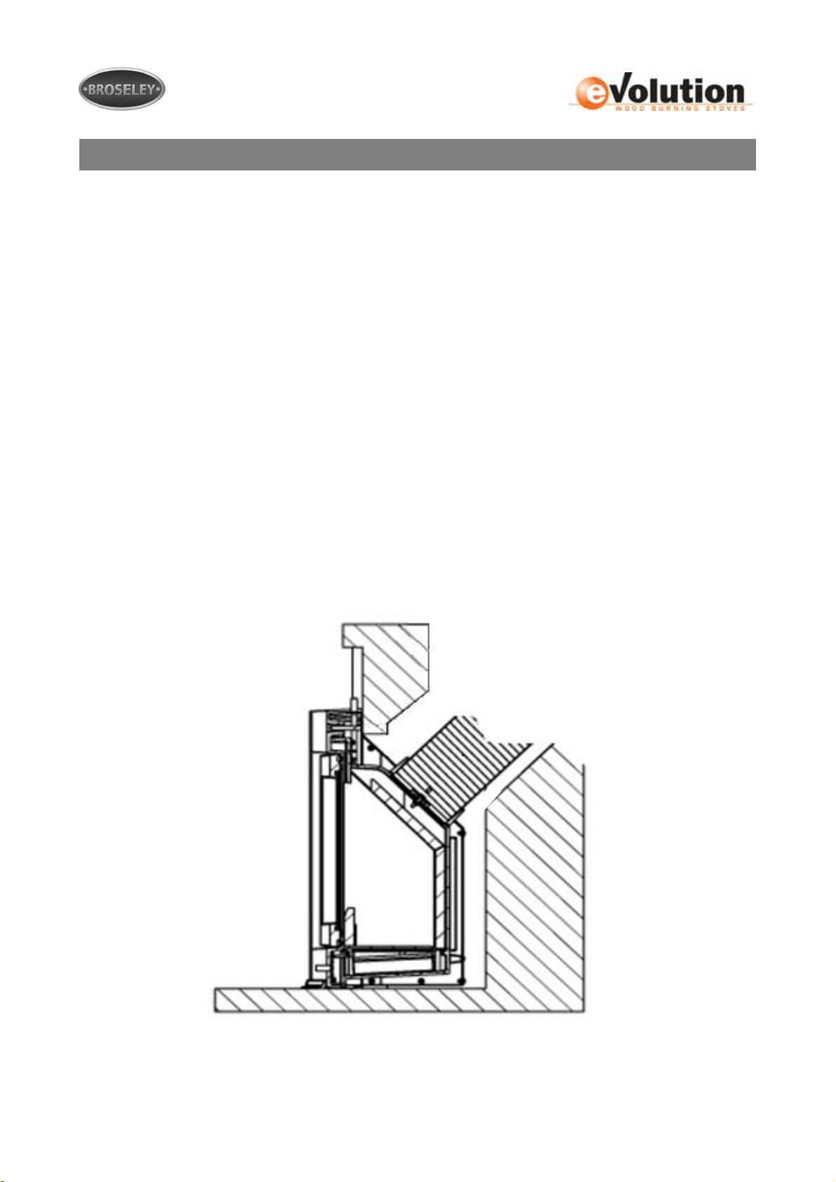
Clearances to combustibles are detailed in the diagram below. 300mm above and 100mm
to the side must be obtained to any flammable material such as wooden surrounds for
example. These figures are based on the fact that the stoves forward projection is no more
than 150mm.
Stove Clearances Rear Side Hearth Above
Non-Combustible 0mm 0mm 300mm 0mm
Combustible 100mm 100mm 300mm 300mm
MS11-11 Issue 3 7
Page 8

Chimney Requirements
This appliance must not be fitted into a chimney serving another heating appliance. It is
most important that there is no obstruction in the flue or chimney. Please ensure that any
existing chimney is clear of obstruction and swept clean immediately before installation of
the new stove. If the chimney has been used for an open fire it is recommended that it be
swept for a second time having been used for a month following installation.
A flue draught minimum of 12 Pascals to a maximum 16 Pascals is required for
satisfactory appliance performance. A properly built masonry or factory constructed
chimney (with a minimum vertical height of 5 metres) should ensure a consistent draught
(draw).
The flue draught should be checked under fire at high output. If you have any doubts about
the suitability of your chimney, consult your local dealer/stockist or engineer. If your flue
draft is below the minimum recommendation then it may be necessary to increase the
vertical chimney height, add additional flue insulation or possibly add a special cowl to the
top of the chimney (e.g. anti down draft cowl to eliminate wind induced down draft).
The outlet from the chimney should be above the roof of the building in accordance with
the provisions of Building Regulations Approved Document J.
If installation is into an existing chimney then it must be sound and have no cracks or other
faults which might allow fumes into the house. Older properties, especially, may have
chimney faults or the cross section may be too large i.e. more than 230 mm x 230 mm.
Remedial action should be taken, if required, seeking expert advice, if necessary. If it is
found necessary to line the chimney then a flue liner suitable for solid fuel must be used in
accordance with Building Regulations Approved Document J.
If there is no existing chimney then either a prefabricated block chimney in accordance
with Building Regulations Approved Document J or a twin walled insulated stainless steel
flue to BS 4543 can be used. These chimneys must be fitted in accordance with the
manufacturer’s instructions and Building Regulations.
The stoves flue spigot is designed to accept a 6” / 150mm diameter pipe, it is possible to
connect the flexible liner to the spigot using self tapping screws. If no flexible liner is
present, the stove will need to be securely sealed into the fireplace opening (see section
“Assembly” for further information).
For sweeping purposes it is possible to sweep through the appliance, however you will
need to remove the internal baffle(s) to do so (see section “Assembly” for further
information).
MS11-11 Issue 3 8
Page 9

Combustion Air Requirements
In order for the stove to perform efficiently and safely there should be an adequate air
supply into the room in which the stove is installed to provide combustion air. This is
particularly necessary in modern houses where drafts have been almost eliminated by
double glazing etc.
Under UK building regulations any appliance over 5kW MUST have a fixed
permanent air vent (see building regulations approved document J for further
information).
There must not be an extractor fan fitted in the same room as the stove as this can cause
the stove to emit fumes into the room. It is necessary to install a wall vent to provide the
necessary combustion air and to prevent the depletion of oxygen in the room.
MS11-11 Issue 3 9
Page 10
Assembly
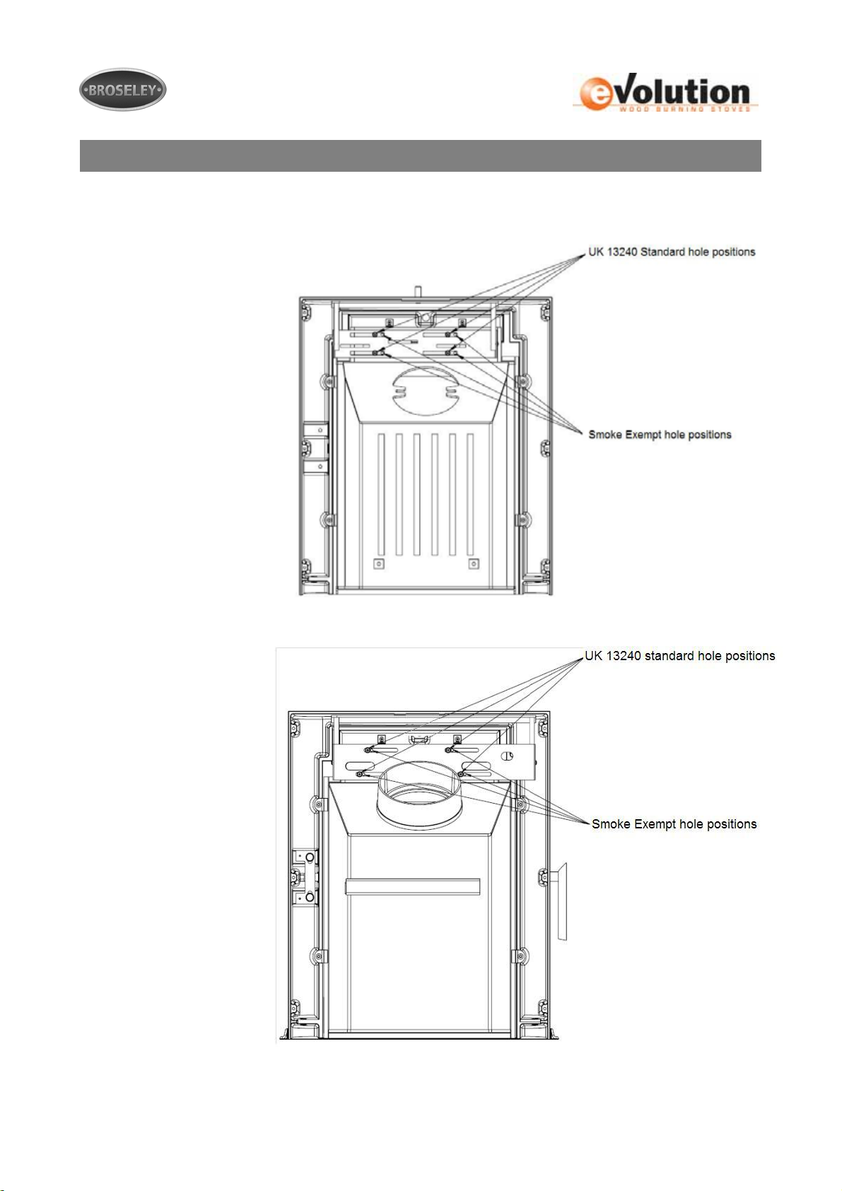
Smoke Exempt modification.
With both the Evolution 4 &
7 when it comes to
installations in smoke
control areas, you will need
to adjust the secondary air
intake to ensure
permanent combustion air.
You will need to remove
the six screws holding the
rear steel cover in place,
once you have removed
the cover you will be able
to see the mechanism
fixings as shown. The
fixings indicated will need
to be removed and re-fixed
one position to the right
(one at a time).
Evolution 4
Evolution7
MS11-11 Issue 3 10
Page 11
Assembly
Liner Connection
Unbolt the flue spigot from the stove (done by removing the internal baffle to access the
fixings). Connect and seal the 150mm diameter flexible flue liner into the flue spigot, this
can be done by screwing the liner using the 2 holes located in the spigot.
Extra care should be taken to ensure an air tight seal between the liner and the spigot.
(additional rope and or fire cement may be required).
Finally insert the stove into the fireplace and connect the flue spigot to the appliance by
means of the 2 bolts supplied. The spigot fixings are accessed from the inside of the stove.
IT IS RECOMMENDED THAT THIS STEP IS COMPLETED AFTER FIRST SITING THE
STOVE AND ENSURING SECURE POINTS ARE MARKED AND OR DRILLED.
Un-lined Chimney Connection
If the chimney is not being lined it is important that the stove is securely sealed into the
opening (a gas tight seal to BS 8303-1). A 12mm self adhesive rope is supplied to assist
with this, however additional sealant may be required to ensure a sound seal. The seal
needs to continue at hearth level as well as sides and top.
MS11-11 Issue 3 11
Page 12
Assembly
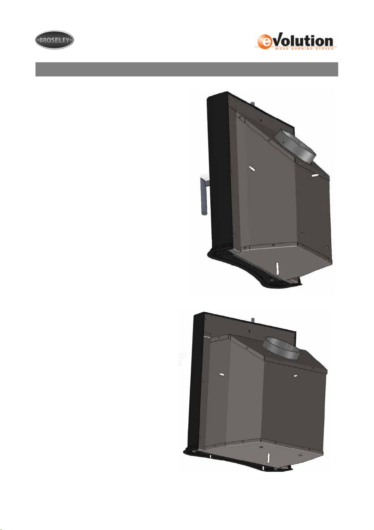
With both the Evolution 4 & 7 insert stoves,
several fixing points are provided for ease of
installation. The fixing points will come sealed
using a bolt and nut, which simply need to be
removed from the appropriate fixings.
Screws/fixings are not provided with the
stove as these will need to suit the hearth
and surround material.
Evolution 4
Evolution 7
MS11-11 Issue 3 12
Page 13
Assembly
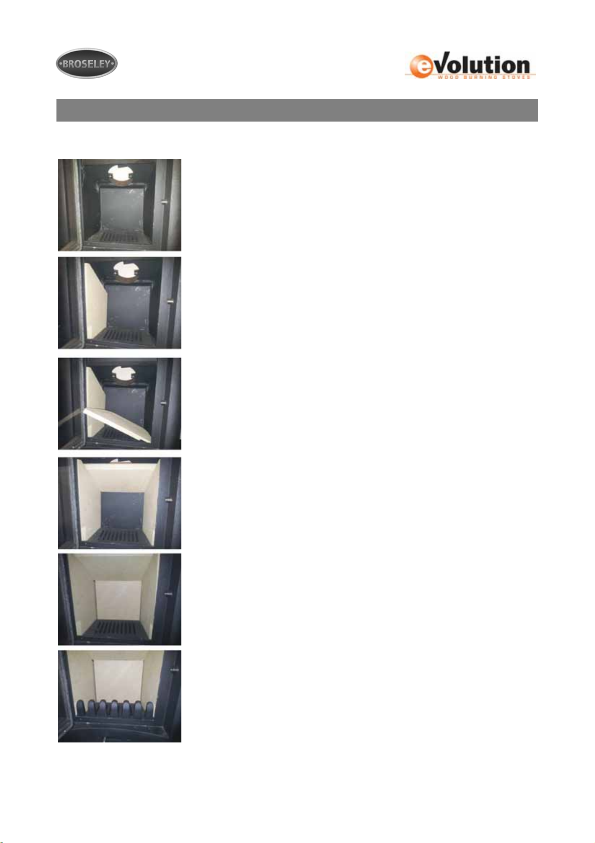
The images below detail the sequence for installing the internal firebricks in the eVolution 4
1. Ensure there is no ash are debris to prevent the
firebricks installation.
2. Start by installing the left side firebrick as shown.
3. Insert the right side firebrick but this time lean it towards
the left brick as shown.
4. Insert the baffle, lift the baffle upwards towards the roof
with one hand and with your other hand stand the right
firebrick upright as shown. You can now lower the baffle
so that it rests on each of the side firebricks as shown.
5. Insert the rear firebrick, use one hand to lift the baffle up
slightly then position the rear firebrick and lower the
baffle onto it as shown.
6. Finally install the log retainer one side at a time.
To remove the firebricks simply reverse this sequence.
MS11-11 Issue 3 13
Page 14
Assembly
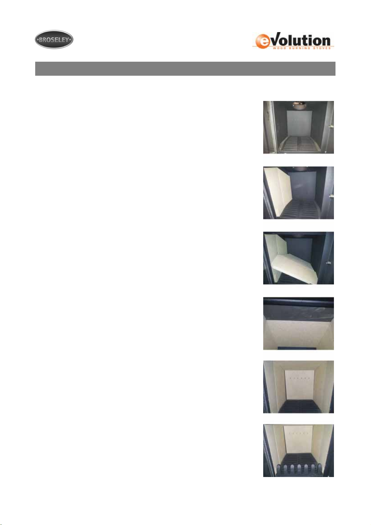
The images below detail the sequence for installing the internal firebricks in the eVolution 7
1. Ensure that the firebox is clear of anything that might
obstruct the firebrick installation.
2. Insert the left hand side firebricks (this piece is in two
sections) as shown.
3. Insert the right hand side firebricks (also in two sections)
this time lean the firebricks to the left as shown.
4. Next insert the steel and vermiculite baffles (steel at the
front) you need to hook the left edge of each baffle onto the
left side firebricks. With one hand lift the two baffles up
together, with your other hand lift the two right side bricks
Into position. Allow the baffles to rest onto the side bricks as
shown.
5. Next insert the rear firebrick (larger holes go to the back).
You may need to lift the rear baffle up slightly whilst
positioning this firebrick. Once in place the baffle should rest
onto the rear firebrick as shown.
6. Finally insert the log retainer one side at a time as shown.
MS11-11 Issue 3 14
Page 15
Controls Layout
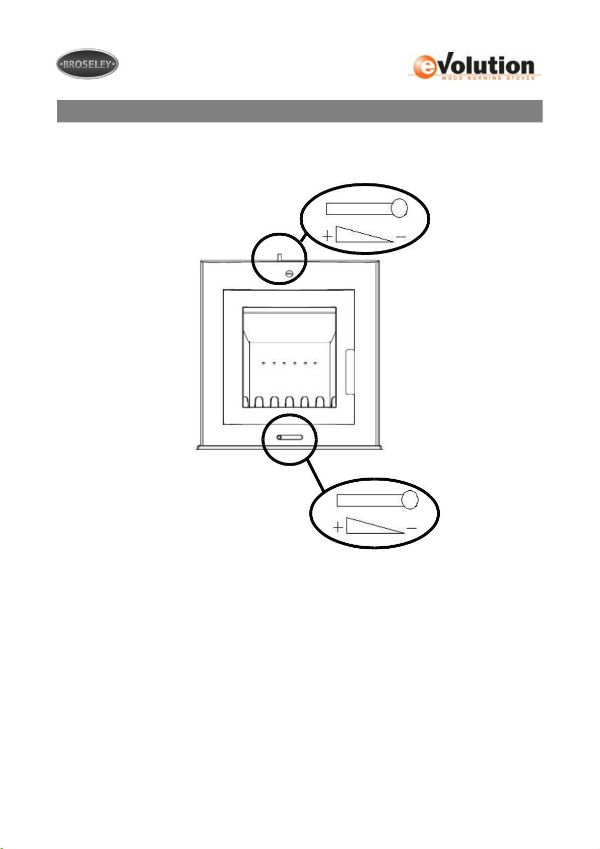
The diagram below shows the position of the air controls, these controls need to be
operated correctly to control the combustion rate of the stove.
The top air control is classed as the “Secondary Air Intake” as it brings air in above the
grate. The lower air control is classed as the “Primary Air Intake” as it brings air in below
the grate.
See the following section for a more detailed description of how this control works.
MS11-11 Issue 3 15
Page 16

Controls Explained
Fire needs air to burn therefore the stove is fitted with air controls that allow you to
regulate the amount of combustion air therefore controlling the burn rate within the
appliance.
Secondary Air Intake
The secondary air intake is located on the top of the stove, it is in the form of a slider.
Having the slider pushed to the right indicates that the air intake is in the closed/minimum
position and to the left indicates it is in the fully open/maximum position.
In smoke controlled areas you should fit the smoke exempt washer behind the control, this
will prevent the control from fully closing.
Air entering through this control is directed through the holes in the rear firebrick and also
down the inside of the glass creating the AIRWASH system – see below. The air wash
system allows the glass to remain soot and particle free. This control is used at initial
lighting and to control the burn rate of your wood.
The sections LIGHTING THE STOVE & BURNING WOOD give a step by step guide on
how to operate this control.
Primary Air Intake
The primary air intake is located below the door and is also in the form of a slider. Having
the slider pushed to the right indicates that the air intake is in the closed/minimum position
and to the left indicates it is in the fully open/maximum position.
The primary air intake is used at initial initial lighting to provide additional air to heat the
chimney/flue.
Air wash System
Air wash is a system where secondary air is drawn into the stove (by combustion) through
the secondary air control and is deflected down the back face of the glass, thus preventing
the smoke coming into contact with the glass. It does not mean that you will never have to
clean the glass, but substantially lengthens the periods between having to do so. The airwash system works best when burning dry wood. Wet wood will produce more deposits
on the glass. Also, deposits will form on the back of the glass when the stove is operated
on low heat for extended periods (where fuel is only just smouldering).
MS11-11 Issue 3 16
Page 17

Recommended Fuels
The HETAS Ltd. appliance approval along with approval in a smoke controlled area only
covers the use of the following fuels in this appliance:
• Wood logs not exceeding 20cms in length and 8×8cm thick. The fuel must not
contain halogenated organic compounds or heavy metals as a result of treatment
with wood preservatives or coatings.
Approval does not cover the use of other fuels either alone or mixed with the suitable fuels
listed above, nor does it cover instructions for the use of other fuels.
Do NOT burn wet wood, This will give a poor heat output and will cause heavy deposits
of soot and tar to accumulate on the glass and throughout the stove and flue. The coating
of soot and tar in the chimney is volatile creating a high risk of chimney fires. A growing
tree contains a high percentage of water, the wood needs to be dried out (seasoned)
before it is suitable for burning (this can take several years). Wood logs are best stored in
a stack, sheltered from the weather, in a well ventilated area and raised off the ground.
This allows the air to circulate and prevents mildew.
Do NOT burn pallet wood or wood containing paint, glue or other chemicals. Burning this
type of wood will result in damage to the appliance, any such damage will not be covered
by the products warranty.
MS11-11 Issue 3 17
Page 18
Lighting the S t ove
Curing
On initial firing you will notice a very pungent odour, this is caused through the curing of
the paint, we recommend starting with short burning sessions (with smaller quantities of
fuel) and build up gradually to allow the components of the stove to settle. Opening doors
and windows will allow the paint curing odour to dissipate and to allow ventilation into the
room. Curing times can vary but typically should take around 8-12 hours (operation at high
output) to complete.
Kindling
Stage 1
With the Primary and Secondary air intakes in the fully open position and the door open,
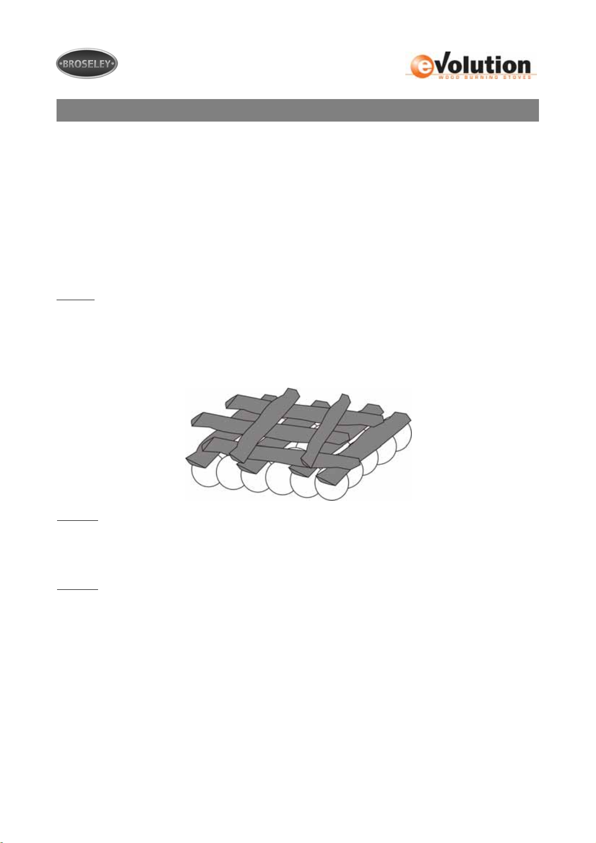
start your fire using twists/balls of newspaper. Form a bed on the grate using the
newspaper (or place several fire-lighters), then add a generous amount of dry kindling
onto the newspaper. Ensure their is sufficient air gaps between the kindling (a criss cross
or pyramid style pattern is ideal to accomplish this).
Kindling -----------
Newspaper -------
Stage 2
Ignite the paper underneath using a match or suitable fire-lighter. Allow the paper and
kindling to burn until it reduces down into hot embers. If the fire is dying during this stage
the door can be closed but not latched leaving a small gap for extra combustion air.
Stage 3
Add another generous load of dry kindling and allow to burn down.
It may be necessary to repeat stage 3 if the chimney is cold or if you find you have smoke
entering the room. This stage is vital for getting heat into the chimney which will create the
draw that takes the smoke away, we would expect this stage to take between 15-20
minutes.
It is critical that you do not leave the stove during the entire lighting and kindling
stage. See Burning wood section for the next steps in the sequence.
MS11-11 Issue 3 18
Page 19

Burning Wood
Once you have kindled your stove (see previous page) and your chimney (flue) is
sufficiently heated and a large base of burning embers is present, you are ready to start
adding you logs.
Stage 4
Place 1-3 small logs onto the bed of hot embers using the gloves provided, close the door
but leave both air intakes in the fully open/maximum position. Allow the logs time to fully
ignite and turn black then close the primary air intake fully (leaving secondary fully open).
Stage 5
Once the smaller logs have burned down you can now add 2-3 larger (or full size) logs.
Leave the secondary air intake fully open until the new fuel turns completely black. You
can now close down the Secondary Air Intake as required. You will now need to control the
burn rate of the stove using the secondary air intake. You are looking for a controlled flame
(not smouldering in the embers or licking around the lid) this is mostly visual although a
flue pipe thermometer will help you determine the amount of air required and is
recommended for the initial lightings.
Stage 6
Refuel as and when required. Take care to open the door gradually as flames may lick out
and always use the gloves. Try to avoid closing the Secondary air control fully (as this will
cause the stove to fill up with smoke) If you no longer want to keep the fire going simply
allow it burn out.
Please note this is the standard lighting/ignition sequence, however there are some
changes to this when burning in a smoke control area. Please see “Smoke Exempt
Requirements” on the following pages.
MS11-11 Issue 3 19
Page 20

Smoke Exempt Requirements
The Clean Air Act 1993 and Smoke Control Areas
Under the Clean Air Act local authorities may declare the whole or part of the district of the
authority to be a smoke control area. It is an offence to emit smoke from a chimney of a
building, from a furnace or from any fixed boiler if located in a designated smoke control
area. It is also an offence to acquire an "unauthorised fuel" for use within a smoke control
area unless it is used in an "exempt" appliance ("exempted" from the controls which
generally apply in the smoke control area).
The Secretary of State for Environment, Food and Rural Affairs has powers under the Act
to authorise smokeless fuels or exempt appliances for use in smoke control areas in
England. In Scotland and Wales this power rests with Ministers in the devolved
administrations for those countries. Separate legislation, the Clean Air (Northern Ireland)
Order 1981, applies in Northern Ireland. Therefore it is a requirement that fuels burnt or
obtained for use in smoke control areas have been "authorised" in Regulations and that
appliances used to burn solid fuel in those areas (other than "authorised" fuels) have been
exempted by an Order made and signed by the Secretary of State or Minister in the
devolved administrations.
Further information on the requirements of the Clean Air Act can be found here:
http://smokecontrol.defra.gov.uk/
Your local authority is responsible for implementing the Clean Air Act 1993 including
designation and supervision of smoke control areas and you can contact them for details
of Clean Air Act requirements
The eVolution Inset Wood burning stoves have been tested by GASTEC under the
PD6434 standard and have passed the emission requirements for exemption under the
Clean Air Act. Subsequently it has been exempt for use in smoke control areas when
burning wood only. Below are detailed operation techniques that must be adhered to
at all times when burning in a smoke control zone.
MS11-11 Issue 3 20
Page 21

Smoke Exempt Requirements
eVo 7 Inset - Ignition
The procedure adopted for ignition is to build a bed of embers in stages with the objective of
warming the stove as quickly as possible. Firstly, a double handful of kindling (equivalent to the
weight of about 1 kg) should be lit with chemical fire-lighters. The primary air and secondary air
controls must be fully open at this stage. The fire door needs to be pushed against the latch but
not closed, leaving a gap of a few millimetres. After about 8 minutes, with the fire bed dying back, 3
half sized logs (total weight about 1.2 kg) should be added with the air controls unaltered. After
approximately a further 2 minutes, when these logs are well alight the door and primary air supply
can be closed. Then allow the fire to burn down to embers with the secondary air supply
maintained at maximum, at which point the ignition sequence is deemed to have ended.
Evo 7 Inset - Refuelling
The refuelling procedure adopted for the PD6434 tests allows the newly charged fuel to burn with
the door set on the latch but not closed, the primary control set fully open for 1 2 minutes and the
secondary air set in the required positions necessary for the various outputs. After 1 2 minutes,
with the logs burning well, the door and primary air supply needs to be closed but the secondary air
control position can remained unaltered. The tertiary air supply is maintained with its permanent
opening throughout.
Evo 4 Inset – Ignition
The procedure adopted for ignition is to build a bed in stages and to warm the body of the
appliance and the chimney as quickly as practicable. Firstly kindling, weighing approximately 1 kg
will need to be lit (using a chemical fire-lighter is recommended) with the air control fully open. The
door must be pushed against the appliance but then left ajar. After about 10 minutes, when the fire
from the kindling is beginning to die back, two small logs can be added. When these are alight and
fully blackened, the door can be closed. This, typically, takes approximatel y a further five minutes.
When the fire is again beginning to die back, a full load of two logs, weighing about 1.3 1.4 kg,
can be added: typically this takes 20 – 25 minutes from the start of the ignition sequence. The
Secondary air control must be maintained in its fully open position for the remainder of the ignition
sequence. Once the fuel has blackened the fire can then be allowed to burn down to a suitable
condition at a preferable air slider position. For start of further re fuelling apply sequence in the
previous 2 sentences.
Evo 4 Inset – Refuelling
There is a requirement for the door to be left ajar for 3 minutes immediately after refuelling. This is
to ensure that flames are well established on the newly charged logs and that they become fully
blackened. Additionally, for medium and low output burning, the Secondary air contro l must be
Maintained at 100% open for the first 3 minutes after refuelling at which time it is possible to adjust
to the required settings as identified above. The primary air intake is not required at this stage.
MS11-11 Issue 3 21
Page 22

Smoke Exempt Requirements
FURTHER REQUIREMENTS:
1. It is important to follow these instructions in order to achieve clean burning and to
maximise the efficiency from the stove
2. Do not leave the fire unattended after refuelling until flames are well established
on the newly charged logs
3. Refuelling on to a low fire bed If there is insufficient burning material in the fire bed
to light a new fuel charge, excessive smoke emission can occur. Refuelling must be
carried out onto a sufficient quantity of glowing embers and ash that the new fuel
charge will ignite in a reasonable period. If there are too few embers in the fire bed,
add suitable kindling to prevent excessive smoke
4. Fuel overloading The maximum amount of fuel specified in this manual should not
be exceeded, overloading can cause excess smoke.
5. Operation with door left open Operation with the door open can cause excess
smoke. The appliance must not be operated with the appliance door left open
except as directed in the instructions.
6. Dampers left open Operation with the air controls or dampers open can cause
excess smoke. The appliance must not be operated with air controls or dampers
door left open except as directed in the instructions.
MS11-11 Issue 3 22
Page 23

Warning Notes
Over-Firing
It is extremely important that you do NOT leave the air control in the fully open position for
extended periods or run the appliance with the door open. Leaving the air control fully open (or
running with the doors open) will lead to “over-firing”. Over-firing is caused when too much heat is
generated within the fire chamber, this will lead to warping, buckling and general damage to the
stove and its internal components. Over-firing can also be caused by an excessive flue draft.
PLEASE NOTE ANY DAMAGE TO THE APPLIANCE CAUSED THROUGH OVER-FIRING WILL
NOT BE COVERED BY THE WARRANTY.
Fumes
Properly installed, operated and maintained, this appliance will not emit fumes into the dwelling.
Occasional fumes may occur whilst de-ashing and re-fuelling. However, persistent fume emission
is potentially dangerous and must not be tolerated. If fume emission does persist, the following
immediate actions should be taken:-
a) Open doors and windows to ventilate the room
b) Let the fire go out or eject and safely dispose of fuel from the appliance
c) Check for flue or chimney blockage and clean if required
d) Do not attempt to relight the fire until the cause of the fume emission has been
Identified and corrected. If necessary seek expert advice
Firebricks
Vermiculite is an industry recognised robust fireproof material which is used by many stove
manufacturers to produce internal firebox linings (firebricks). With care vermiculite firebricks will
give many years of faithful service.
It is important that care is taken whilst refuelling your stove in order to protect the internal
vermiculite parts from premature failure.
Never throw or drop logs into your stove as this will potentially damage your firebricks and may
also result in logs bouncing out of the appliance (creating a possible fire risk). Open the door an
inch initially (allowing the fire to settle) then slowly open the door and gently place the log(s) onto
the grate. Always use the glove (provided) when refuelling to avoid the common scenario of
dropping the logs in quick (because it’s hot).
Take care when clearing the ash and using the poker tool not to strike and potentially damage your
firebricks.
Always take care when removing the firebricks to avoid damaging them. It may be necessary to
remove the firebricks during general maintenance and chimney sweeping.
Impact damage is the most common cause of cracked vermiculite firebricks; however it is also
possible to crack the firebricks if you over fire your appliance.
MS11-11 Issue 3 23
Page 24

Maintenance
Ash Removal
The ash pan can be removed by using the ash tool to hook out the grate so that you can
grasp the pan using the gloves provided. We would recommend emptying the ash into a
metal bucket for transportation.
You should only empty the ash when the appliance and ashes are completely cool and can
be disposed of in your normal household refuse.
Chimney Fires
In the event of a chimney fire ensure both Primary and Secondary air controls are fully
closed and the door(s) remain closed at all times. If the chimney fire does not go out or if
there is a serious risk to people and property, call the fire brigade immediately.
Regular sweeping of the chimney will remove combustible particles and will reduce the risk
of chimney fires.
Cleaning the Stove
We recommend only doing this when the stove is cold using a soft brush to clean a ny of
the stove surfaces, this is normally sufficient to remove dust, ash and debris. For stubborn
marks you can use a damp lint free cloth, ensure that all surfaces are dried off
immediately. We do not recommend using any kind of chemicals or abrasive materials. It is
possible to touch up the paint using the original metallic black stove paint, however this
new paint will then need to cure.
Glass Cleaning
A damp lint free cloth is normally sufficient, however for stubborn build ups we would
recommend using a very fine wire wool.
Chimney Sweeping
It is essential that your chimney (flue) is swept at least once a year by a registered
professional chimney sweep. Sweeping removes particles that could otherwise fuel a
chimney fire, it should also highlight any potential issues such as leaks and damage to the
flue.
Stove Servicing
Your stove should be inspected annually to ensure all seals are present and correct and to
gauge the condition of the internal firebricks. The service should be done by a HETAS
registered engineer who also perform a spillage test.
MS11-11 Issue 3 24
Page 25

Trouble-shooting
Smoke comes out of the stove when the loading door is opened.
• The chimney cavity into which the 150mm flue pipe has been installed may be
less than the minimum requirement.
• Deposits (soot or other obstructions) may have built up in the chimney and be
restricting the flow of waste products. This flow rate is known as the ‘draw’.
• Insufficient draw, this is especially common during milder weather. You will need
to prolong the kindling stage to ensure the chimney (flue) is completely hot (you
may even need to pre-heat the chimney using a method advised by the installer)
• Combustion air intake is not large enough or another appliance (e.g. Extractor
fan) is taking air away from the sto ve.
The Stove does not produce the expected heat into the room.
• Has the flue pipe been sealed to the chimney to prevent heat being drawn up
the chimney to waste?
• Green or wet wood is being burnt.
• The chimney has excessive draw (this is unusual). Seek installer advice with
regard to installing a Flue Draught Stabiliser.
• The stove has been recessed into the existing fireplace and a lot of heat is being
absorbed by the surrounding fireplace walls rather than being radiated into the
room. Pull the stove forward.
• For the maximum efficiency of heat transference into the room the stove should
be sited on the hearth of the fireplace rather than recessed.
The Stove burns too fast.
• Use whole logs rather than split ones.
• The wood being used may be generally too small.
• The “air-tight” seal between the fibre rope on the doors and the casting may
have been lost, adjust door handle lock nuts to reinstate this seal or replace.
• The chimney has excessive draw (seek installers advice on this point).
• The fibre rope seal between the door and the glass may be leaking. Tighten or
replace.
• The fibre rope on doors and glass has worn out. Replace.
MS11-11 Issue 3 25
Page 26

Commissioning Form
Commissioning Statement and Check-list
Stove Purchased From:_____________________________________________________
Address:_________________________________________________________________
Telephone Inc area code:____________________________________________________
Installation Date:_____/_____/__________ Stove Name:_________________________
Product Serial Number:________________ Invoice Number:_______________________
Stove installed by:_________________________________________________________
Address:_________________________________________________________________
Telephone Inc area code:____________________________________________________
HETAS Registration Number:________________________________________________
Check-list
Is the flue system the correct length and diameter for stove: Yes No
Flue swept and checked for soundness: Yes No
Manufacturers clearances adhered: Yes No
Smoke spillage test performed on stove: Yes No
Stove controls fully explained to end user: Yes No
Correct fuels explained to end customer: Yes No
CO Alarm fitted and tested: Yes No
Instruction booklet & HETAS certificate handed to end user: Yes No
Signature:__________________________ Print Name:___________________________
MS11-11 Issue 3 26
Page 27
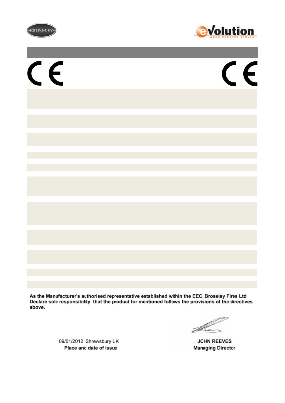
EC Declaration
ACCORDING TO DIRECTIVES 89/106/EEC (CONSTRUCTION
DECLARATION OF CONFORMITY
PRODUCTS)
ISSUED BY:
TYPE OF EQUIPMENT:
TRADEMARK:
MODEL: EVOLUTION 4 INSET STOVE
USE: DOMESTIC SPACE HEATING
MANUFACTURER:
RRF Rhein-Ruhr Feuerstätten Prüfstelle GmbH
NOTIFIED BODY: RRF 1625
KNIGHTS WAY, BATTLEFIELD ENT PARK.
SHREWSBURY. SY1 3AB ph: +44 (0)1743 461444
KNIGHTS WAY, BATTLEFIELD ENT PARK.
SHREWSBURY. SY1 3AB ph: +44 (0)1743 461444
BROSELEY FIRES LTD
WOOD BURNING STOVE
BROSELEY FIRES LTD
BROSELEY FIRES LTD
Firmensitz
Im Lipperfeld 34 b
D-46047 Oberhausen
The following harmonised standards and Technical specifications have been met and comply
with good engineering practice and safety matters in force within the EEC
All CE standards or other documents
EN 13229 CE MARKING INFORMATION - See Instructions
Particular/Smoke Conditions Exempt
Initial Type Test Reports GASTEC 6679-1
MS11-11 Issue 3 27
Page 28
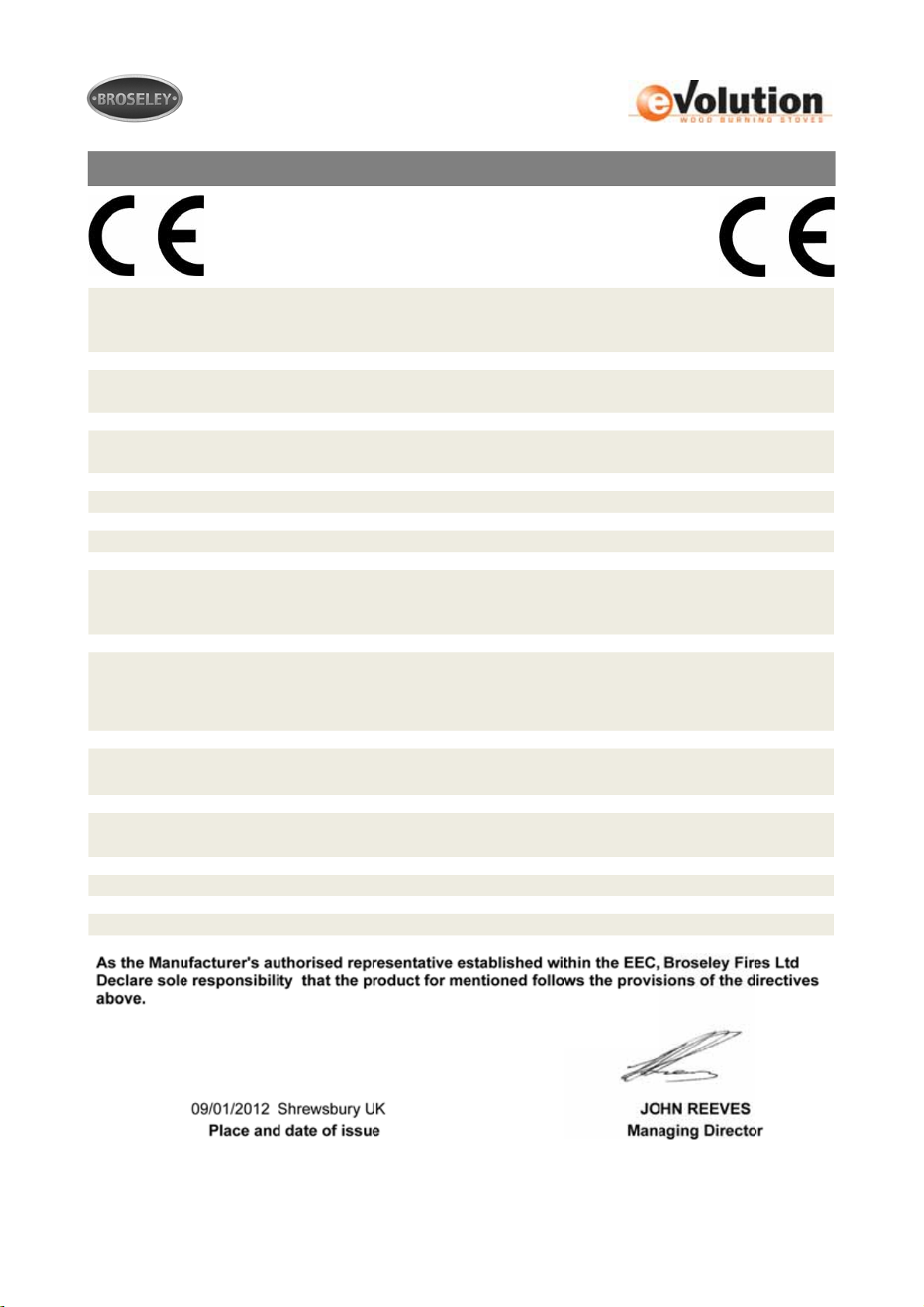
EC Declaration
ACCORDING TO DIRECTIVES 89/106/EEC (CONSTRUCTION
DECLARATION OF CONFORMITY
PRODUCTS)
ISSUED BY:
TYPE OF EQUIPMENT:
TRADEMARK:
MODEL: EVOLUTION 7 INSET STOVE
USE: DOMESTIC SPACE HEATING
MANUFACTURER:
GASTEC AT CRE LTD
NOTIFIED BODY:
GASTEC
0558
KNIGHTS WAY, BATTLEFIELD ENT PARK.
SHREWSBURY. SY1 3AB ph: +44 (0)1743 461444
KNIGHTS WAY, BATTLEFIELD ENT PARK.
SHREWSBURY. SY1 3AB ph: +44 (0)1743 461444
BROSELEY FIRES LTD
WOOD BURNING STOVE
BROSELEY FIRES LTD
BROSELEY FIRES LTD
Stoke Orchard, Cheltenham
Gloucestershire
GL52 7RZ
The following harmonised standards and Technical specifications have been met and comply
with good engineering practice and safety matters in force within the EEC
All CE standards or other documents
EN 13229 CE MARKING INFORMATION - See Instructions
Particular/Smoke Conditions Exempt
Initial Type Test Reports GASTEC 6679-1
MS11-11 Issue 3 28
Page 29

Annual Service Record
1ST YEAR SERVICE completion date:
SERVICE ENGINEER: REG. No.
COMPANY NAME: .
COMPANY ADDRESS: .
POSTCODE:
CONTACT NUMBER
2ND YEAR SERVICE completion date:
SERVICE ENGINEER: . . REG. No.
COMPANY NAME: .
COMPANY ADDRESS: .
POSTCODE:
3RD YEAR SERVICE completion date:
SERVICE ENGINEER: REG. No.
COMPANY NAME: .
COMPANY ADDRESS: .
POSTCODE:
4TH YEAR SERVICE completion date:
SERVICE ENGINEER: REG. No.
COMPANY NAME: .
COMPANY ADDRESS: .
POSTCODE:
5TH YEAR SERVICE completion date:
SERVICE ENGINEER: REG. No.
COMPANY NAME: .
COMPANY ADDRESS: .
POSTCODE:
6TH YEAR SERVICE completion date:
SERVICE ENGINEER: REG. No.
COMPANY NAME: .
COMPANY ADDRESS: .
POSTCODE:
MS11-11 Issue 3 29
Page 30

Warranty
This appliance must be installed and commissioned by a fully qualified, registered engineer. A “Declaration of completion
Certificate” must be obtained for the installation and retained by the end user. Failure to comply w ith the se requirements
may void your warranty.
You, as the end user, have a contract by law with the supplier / dealer from whom you purchased the product. That
dealer then has the same contract with the manufacturer or wholesaler and these have a contract with their suppliers.
ALL CLAIMS MUST FOLLOW TH IS PROCEDURE.
Thank you for choosing a Product from Broseley Fires Ltd. This warranty gives you specific legal rights. The statutory
rights of the consumer are not affected by the warranty, or the consumers’ rights against the dealer arising from their
sales / purchase contract.
The manufacturers’ warranty:
Your Product will be free from defective parts, material, and workmanship at the time of its original purchase for a period
of five (5) year. This Warranty will become active as of one month from the date of delivery.
This warranty does not cover any failure of the unit due to normal wear and tear, misuse, abuse, accident, illegal
modification, illegal installation or repair, damage resulting from improper use or failure to maintain the product.
Variations in color and texture are a natural characteristic of cast iron products. Colour changes may result from
exposure to light and other elements which are a part of the aging process. These material variations and changes ar e
not covered by this warranty. If during the warranty period, this Product fails to operate under normal use and service,
due to defects in material and / or workmanship, Broseley Fires will either repair or replace the product. The repaired or
replaced product shall be warranted for the remaining period of the original warranty + the time taken to days from the
date of repair, whichever is longer.
Repair or replacement may involve the use of functionally equivalent reconditioned units. Replaced parts or components
will become the property of Broseley Fires.
Should you wish to claim under the warranty, please contact the supplier / dealer from whom you purchased the
appliance. Do not claim directly to Broseley Fires, as they are unable to process any direct claim from an end user.
Product design and any specifications are subject to change without notice. This is due to our continuous product
development and improvement. The buyer will not be entitled to request free upgrades to the new design or
compensation for previously purchased products or any products on order.
• This Warranty covers all Broseley Fires costs within the Warranty period.
If the appliance remains uninstalled for a period greater than six months from date of delivery the Warranty will become
active six months from the date of original invoice to the distributor.
I
N NO EVENT SHALL BROSELEY FIRES BE LIABLE FOR INCIDENTAL OR CONSEQUENTIAL DAMAGES OF ANY NATURE WHATSOEVER,
INCLUDING BUT NOT LIMITED TO LOST PROFITS OR COMMERCIAL LOSS, TO THE FULL EXTENT THOSE DAMAGES CAN BE
DISCLAIMED BY LAW. (if applicable)
NON - COVERAGE OF THE GUARANTEE
The consumable items within the product are not covered by the warranty, nor is the glass
If the end-user’s claim should not be covered by this guara ntee, th e end-user shall be liable for costs incurred by
Broseley Fires such as callout and inspection costs for examination of the product, transportation costs of the product as
well as any other relevant costs.
If, after having been informed about the non-coverage of the guarantee, the end-us er wants to have the repairs done, the
end-user shall additionally pay for any spare parts used an d for the labour and transportation costs incurred. If repairs
are carried out under this guarante e , the remaining guarantee period for the product shal l be extended by the period of
time that has elapsed since the complaint was officially logged with Broseley Fires until the repairs have been completed
A COPY OF OUR FULL TERMS AND CONDITIONS IS AVAILABLE ON REQUEST.
** End-user means the natural or legal person who owns the product and who has not acquired it with a view to reselling or installing it
in the course of business
MS11-11 Issue 3 30
 Loading...