

BrookVent AS 90-0102-WIN-01, AS 90-0102-WINS-01, AS 90-0102-CIN-01, AS 90-0102-CINS-01, AS 90-0102-FIN-01 Installation, Maintenance And User Manual
...Page 1
V. 1.2-14-03-17
brookvent.co.uk
Heat Recovery Ventilation
Installation, maintenance
& user manual
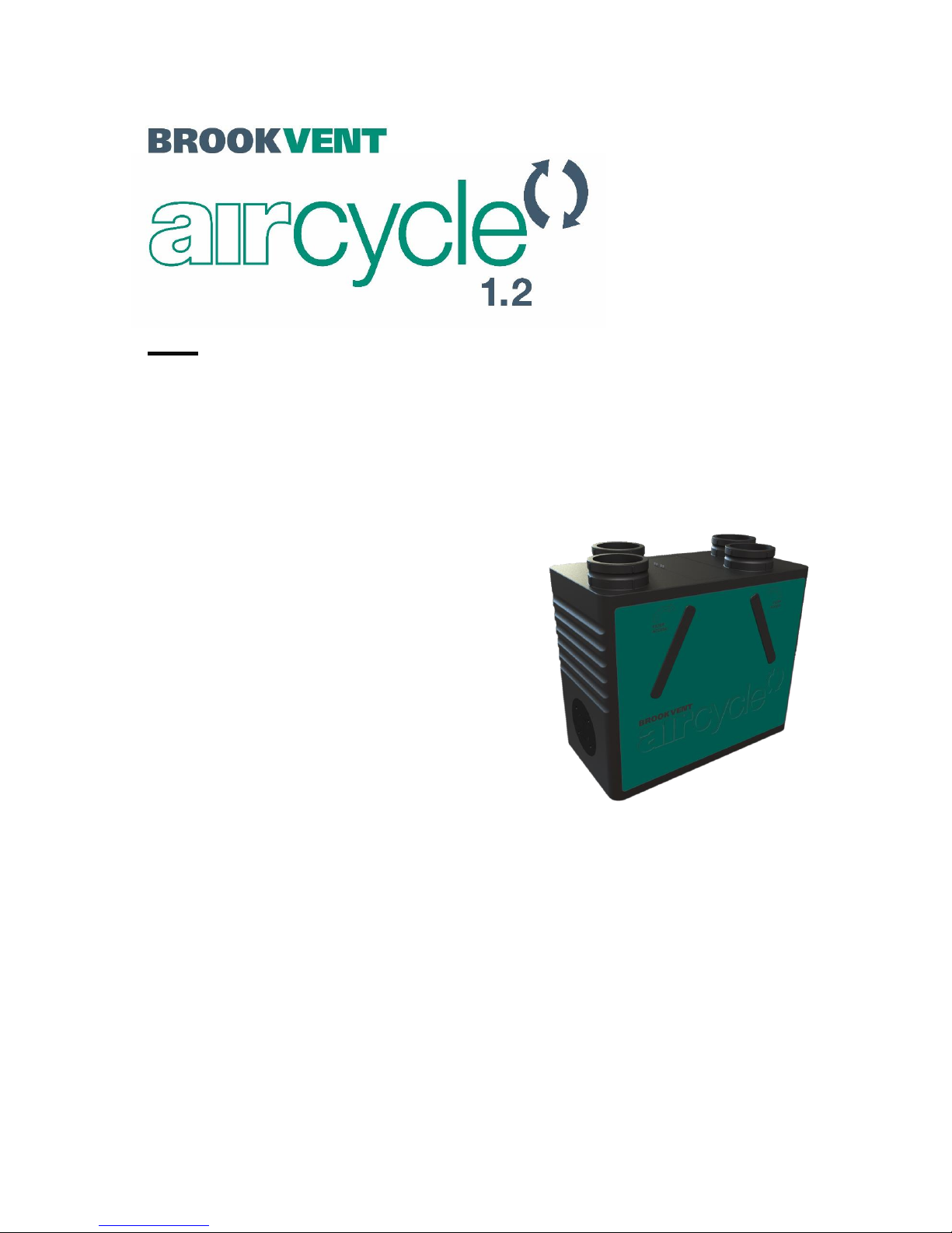
Applicable to the following aircycle 1.2 models:
PRODUCT CODE DESCRIPTION
AS 90-0102-WIN-01 aircycle 1.2 c/w Integral Humidistat - Wall Mount
AS 90-0102-WINS-01 aircycle 1.2 c/w Integral Humidistat & Summer Bypass - Wall Mount
AS 90-0102-CIN-01 aircycle 1.2 c/w Integral Humidistat - Ceiling Mount
AS 90-0102-CINS-01 aircycle 1.2 c/w Integral Humidistat & Summer Bypass - Ceiling Mount
AS 90-0102-FIN-01 aircycle 1.2 c/w Integral Humidistat – Floor Mount
AS 90-0102-FINS-01 aircycle 1.2 c/w Integral Humidistat & Summer Bypass - Floor Mount
(Product codes above refer to ‘standard’ system set up. Add “ V ” to the end of each product code for an ‘inverted’ system set-up
IN A COMPACT PACKAGE
HIGH PERFORMANCE
Page 2

1
V. 1.2-14-03-17
brookvent.co.uk
www.brookvent.co.uk T: +44 (0) 28 9061 6505
CONTENTS
PLEASE KEEP THESE INSTRUCTIONS WITH THE PRODUCT.
Please read this manual fully prior to installing the MVHR unit.
1.0 Introduction ........................................................................................................................ 2
2.0 Safety .................................................................................................................................. 4
3.0 Specifications/ Dimensions (mm) ....................................................................................... 6
4.0 Installation ........................................................................................................................ 11
5.0 Electrical Connections/ Wiring ......................................................................................... 20
6.0 Controls and Settings ........................................................................................................ 22
7.0 Maintenance ..................................................................................................................... 27
8.0 User Operation .................................................................................................................. 29
9.0 Trouble Shooting ............................................................................................................... 31
Page 3

2
V. 1.2-14-03-17
brookvent.co.uk
www.brookvent.co.uk T: +44 (0) 28 9061 6505
IMPORTANT
This appliance is not intended for use by persons (including children) with reduced
physical sensory or mental capabilities, or lack of experience and knowledge, unless
they have been given supervision or instruction concerning use of the appliance by a
person responsible for their safety.
1.0 Introduction
The Brookvent aircycle 1.2 is a compact and highly efficient Mechanical Heat Recovery
Ventilation (HRV/MHRV) system, specifically designed for smaller dwellings and
apartments with restricted space.
The system should be run continuously 24 hours a day, and should only be disconnected
by a competent person during service or maintenance.
Heat Recovery ventilation works best in new homes, which are extremely airtight and
have high efficiency ratings. These dwellings require a high level of fresh air to ensure a
healthy living environment.
The system works by drawing stale air from ‘wet rooms’ such as Bathrooms, WC’s and
Kitchens, recovering up to 93% of the heat from this air using a highly efficient heat
exchanger, before expelling waste air from the home. Simultaneously, fresh air is drawn
into the home, filtered and warmed by the recovered heat and supplied into the
‘habitable rooms’ such as bedrooms, dining rooms and living rooms.
Page 4

3
V. 1.2-14-03-17
brookvent.co.uk
www.brookvent.co.uk T: +44 (0) 28 9061 6505
1.1 Model Variations
PRODUCT CODE DESCRIPTION
AS 90-0102-WIN-01 aircycle 1.2 c/w Integral Humidistat - Wall Mount
AS 90-0102-WINS-01 aircycle 1.2 c/w Integral Humidistat & Summer Bypass - Wall Mount
AS 90-0102-CIN-01 aircycle 1.2 c/w Integral Humidistat - Ceiling Mount
AS 90-0102-CINS-01 aircycle 1.2 c/w Integral Humidistat & Summer Bypass - Ceiling Mount
AS 90-0102-FIN-01 aircycle 1.2 c/w Integral Humidistat – Floor Mount
AS 90-0102-FINS-01 aircycle 1.2 c/w Integral Humidistat & Summer Bypass - Floor Mount
(Product codes above refer to ‘standard’ system set up. Add “ V ” to the end of each product code for an ‘inverted’ system se t-up
1.2 Product Guarantee
This product is guaranteed against defects for a period of 5 years from date of purchase
with the first year covering parts and labour and the remaining 4 years covering parts
only.
In the instance of a defect, Brookvent may repair the product, replace the product free of
charge or refund the cost of the product at Brookvent’s own discretion. In terms of
installation, operation and maintenance please follow all instructions provided. If this
product has been misused, not properly maintained or handled carelessly it may lead to
this guarantee being declared void.
Brookvent does not accept liability for damage caused by non-observance of the
installation instructions. Service activities must be carried out by Brookvent or by
competent installers using original Brookvent parts. This guarantee does not affect your
statutory right as a consumer.
Brookvent operate a policy of continuous innovation and improvement and thus
reserve the right to alter product specifications and appearances without notice.
Page 5

4
V. 1.2-14-03-17
brookvent.co.uk
www.brookvent.co.uk T: +44 (0) 28 9061 6505
2.0 Safety
The following information must be read carefully to ensure safe installation and
operation of the Brookvent HRV system.
2.1 General Safety
Do not use this appliance for functions other than those described in this booklet.
Never touch the appliance with wet hands.
The unit is only suitable for 230 VAC/50Hz electric mains.
Never modify the fan or electronics, all repairs must be conducted by Brookvent.
Never connect the power if electronics cover is not fitted.
Do not store inflammable products in close proximity to the unit.
If cleaning/ dusting the external surface, do so with a dry cloth only.
2.2 Responsibility of the Installer
Correct Installation, balancing and commissioning of the MHRV unit.
Record measured air flow volumes on each of the valves at High and Low rate.
Compliance to requirements and local additional rules.
Explanation of the ventilation system to the user.
Warning for the user, to check or replace the air filters on time.
All the above, as set out in the latest edition of the Domestic Ventilation
Compliance Guide and the SAP Appendix Q – Installation Guide and Checklist
specific to the UK market.
2.3 Responsibility of the Occupant
Replacement of the filters as per the recommended/ required interval.
Cleaning the valves in the rooms regularly to prevent blockage.
To ensure that the system is functioning properly on a regular basis
To use manual boost switches (where provided) to prevent build-up of pollutants
or mould growth.
Page 6

5
V. 1.2-14-03-17
brookvent.co.uk
www.brookvent.co.uk T: +44 (0) 28 9061 6505
IMPORTANT
Dirty or clogged filters may cause inadequate ventilation in the home which may lead to
air quality issues. It is important that the filters are changed at least once per year or as
required.
In new build properties it may be prudent to check/ change your filters after the first 3
months of occupancy depending on the amount of residual ‘building dust’ present
within the property. Failure to do so will affect your warranty.
Filters can be purchased directly online from brookvent.co.uk
Page 7
6
V. 1.2-14-03-17
brookvent.co.uk
www.brookvent.co.uk T: +44 (0) 28 9061 6505
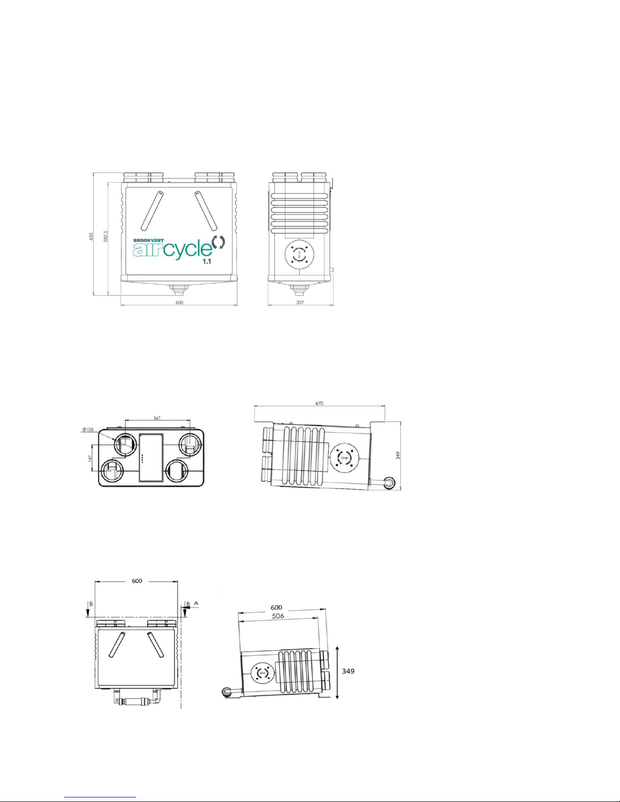
3.0 Specifications/ Dimensions
3.01 WALL MOUNT
H 583mm x W 600mm x D 337mm
3.02 CEILING MOUNT
L 670mm x W 600mm x D 349mm
3.03 FLOOR MOUNT
L 670mm x W 600mm x D 349mm
Page 8
7
V. 1.2-14-03-17
brookvent.co.uk
www.brookvent.co.uk T: +44 (0) 28 9061 6505
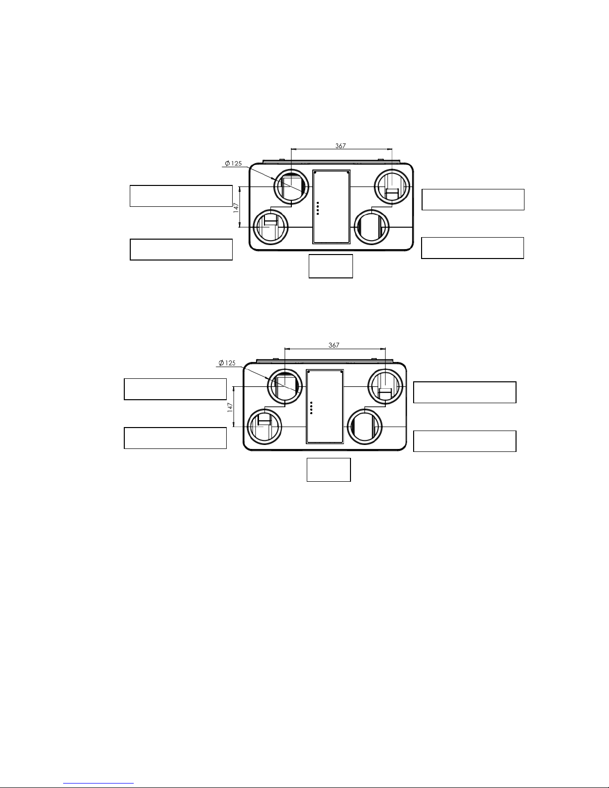
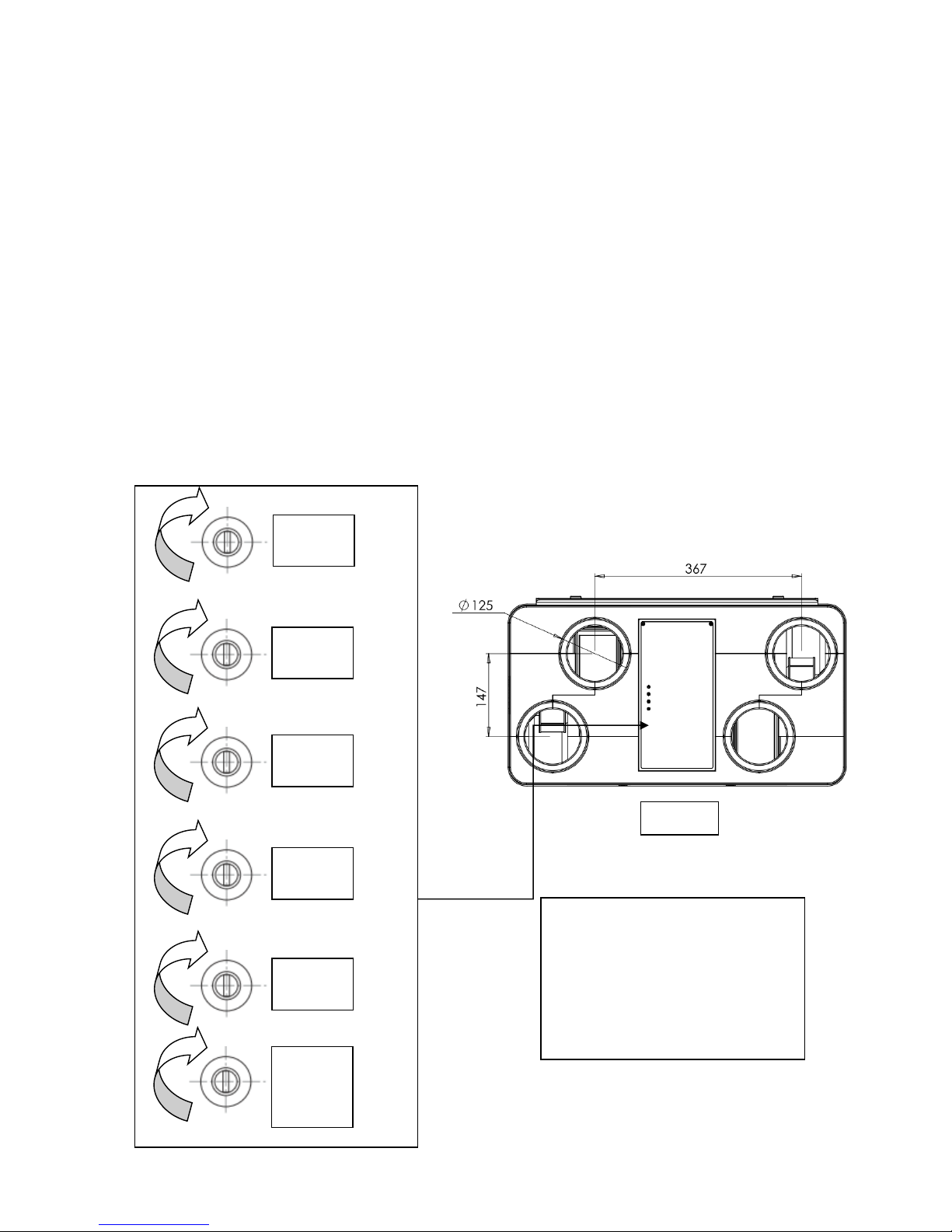
3.1 Duct Connections
Standard Configuration:
Inverted Configuration: (Factory Set: Must be specified at time of order)
Fresh from Outside
Fresh to Home
Extract to Outside
Extract from House
Fresh from Outside
Fresh to Home
Extract to Outside
Extract from House
FRONT
FRONT
Page 9

8
V. 1.2-14-03-17
brookvent.co.uk
www.brookvent.co.uk T: +44 (0) 28 9061 6505
3.2 Detailed Specification
Weight: 10kg
Materials:
• Main enclosure: High density, impact resistant EPP (Expanded Polypropylene)
• PCB & control panel enclosure: ABS FR
• Drainage tray: PP
• Filters: Polyester media (G2/3)
• Filter cover: Rubber
• Mounting Bracket: Zinc Plated Steel
Electrical:
• 230v EC Low energy, backward curved centrifugal fans
• PCB c/w potentiometer control
• Supplied complete with 4 core flying lead: (Live: Brown), (Neutral: Black),
(Earth: Yellow & Green), (230v Switched Live (Boost): Grey)
Controls:
• Independent fan speed control (Trickle and boost settings for each fan)
• Single 230v boost input (Light switch, humidistat, PIR, etc.)
• Boost over-run timer, adjustable between 0 - 15 min.
• In-built humidity sensor (Boost activation) Variable: 60% - 100% RH, factory set: 70%
• Frost protection, factory set at 5 degrees Celsius.
• Tempering summer bypass (Automatic variation between 20 - 27 Degrees Celsius.
Optional
Installation: Wall, Ceiling or Floor Mount
Standards:
Fully complies with Building Regulations for UK & Ireland
SAP Appendix Q Listed | Energy Savings Trust Best Practice | CE
Guarantee Period: 5 Years
Page 10

9
V. 1.2-14-03-17
brookvent.co.uk
www.brookvent.co.uk T: +44 (0) 28 9061 6505
3.3 SAP Appendix Q Results
SAP 2009 (See SAP - PCDB for further details) http://www.ncm-pcdb.org.uk/sap/
SAP 2012 (See SAP - PCDB for further details) http://www.ncm-pcdb.org.uk/sap/
Exhaust Terminal
Configuration
Fan Speed
Setting
Specific
Fan Power
(W/l/s)
Heat Exchange
Efficiency (%)
Kitchen + 1 Wet
Room
100 %
Variable
0.53
93
Kitchen + 2 Wet
Room
100 %
Variable
0.57
91
Kitchen + 3 Wet
Room
100 %
Variable
0.67
90
Kitchen + 4 Wet
Room
100 %
Variable
0.82
89
Kitchen + 5 Wet
Room
100 %
Variable
0.97
88
Kitchen + 6 Wet
Room
100 %
Variable
1.16
87
Exhaust Terminal
Configuration
Fan Speed
Setting
Specific
Fan Power
(W/l/s)
Heat Exchange
Efficiency (%)
Kitchen + 1 Wet
Room
100 %
Variable
0.59
91
Kitchen + 2 Wet
Room
100 %
Variable
0.74
91
Kitchen + 3 Wet
Room
100 %
Variable
0.96
88
Kitchen + 4 Wet
Room
100 %
Variable
1.20
87
Kitchen + 5 Wet
Room
100 %
Variable
1.46
86
Page 11
10
V. 1.2-14-03-17
brookvent.co.uk
www.brookvent.co.uk T: +44 (0) 28 9061 6505
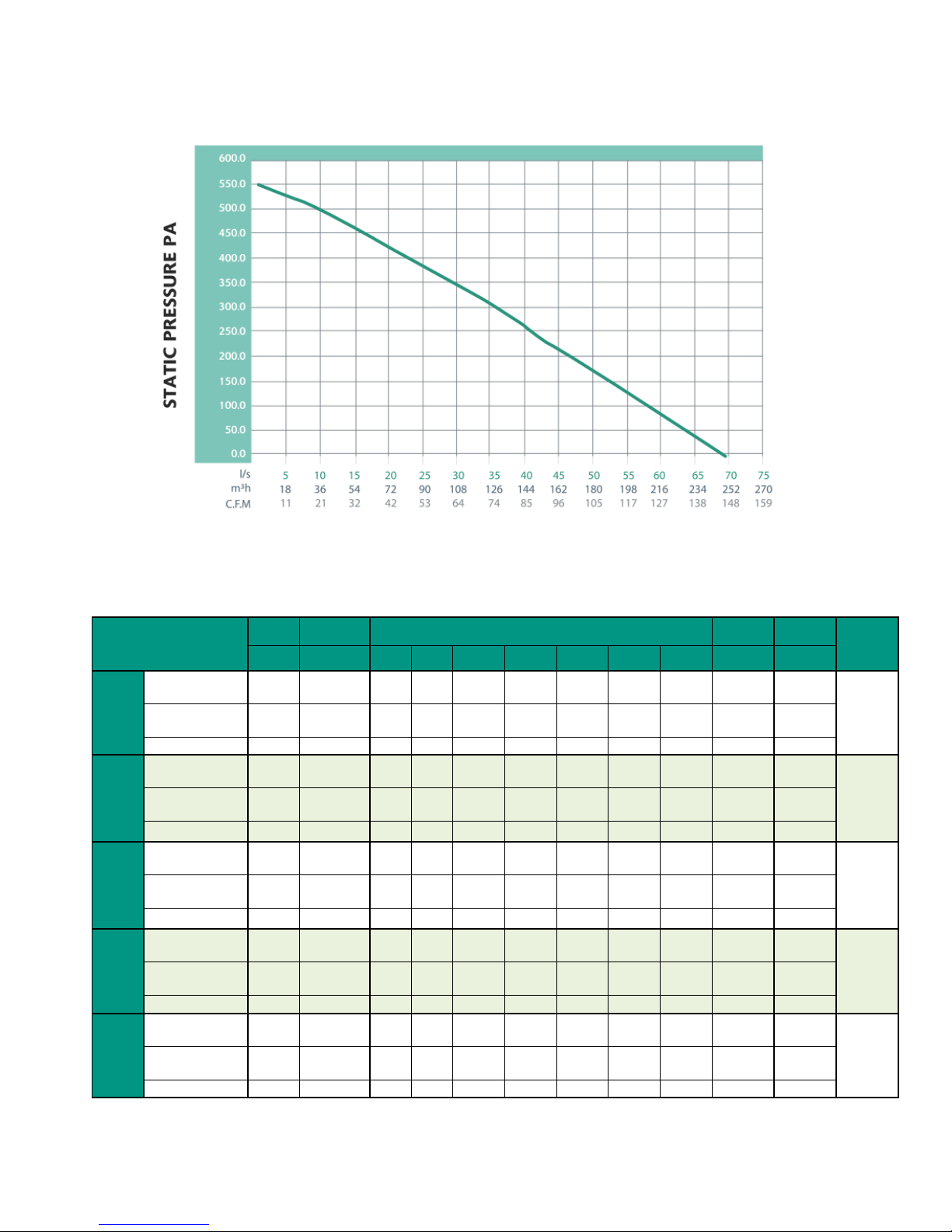
3.4 Airflow: Pressure/ Performance Curve
3.5 Acoustic Information
Pressure
Lf (MAX)
Overall
Overall
Breakout
dBA @
3M
(l/s)
(Pa)
125
250
500
1000
2000
4000
8000
Lw
Lwa
Speed
1
Open Supply
Duct
16 6 32.3
32.7
36
37.8
28.5
21.9
19.2
37
31
10
Open Extract
Duct
17 2 30
26.9
30.7
33.2
25.4
19.2
18.1
34
28
Breakout
19 4 27.4
26
32.6
30.5
29.6
22.1
19.6
34
28
Speed
2
Open Supply
Duct
28
12
28.2
39.2
52.5
50.1
42.4
33.9
24.7
49
44
19
Open Extract
Duct
29
10
31.7
29.7
47.3
40
33.3
28
22.2
41
34
Breakout
31 9 30.8
33.6
46.4
46.8
34
27.4
21.4
43
37
Speed
3
Open Supply
Duct
38
18
33.8
40.8
56.7
55.8
51.7
42.6
30.3
56
46
24
Open Extract
Duct
42
25
37.8
34.3
50.6
49.1
34.9
34.2
24.8
48
41
Breakout
42
16
28.7
33.3
50.3
46.2
40.4
33.8
25.4
48
41
Speed
4
Open Supply
Duct
49
31
48.3
44.8
61.3
64.5
56.9
50.3
39.9
64
55
32
Open Extract
Duct
53
43
45.9
36.2
52..4
59.9
36.5
40.1
26.2
54
50
Breakout
54
30
49.1
35.3
54.1
56.2
47
40.6
35.1
56
50
Speed
5
(max)
Open Supply
Duct
66
40
43.6
47.6
60.4
66.2
63.4
54.2
45.7
64
58
33
Open Extract
Duct
60
55
42
40.5
56.1
58.8
43.2
41.7
39.2
60
51
Breakout
66
40
36.9
35.7
57.4
60.5
52.9
45.4
40.4
60
51
Airflow
Page 12

11
V. 1.2-14-03-17
brookvent.co.uk
www.brookvent.co.uk T: +44 (0) 28 9061 6505
4.0 Installation
It is important that the full installation of this system is carried out by competent persons,
including all electrical works and connections being completed by a qualified electrician.
The MVHR unit is designed to be installed indoors, within an attic, storage cupboard, or
void space, away from exposure to frost, water, or intense heat. The system should be
installed in a ventilated space.
A clear access space is required around the unit; this will ensure ease of installation
relating to ductwork, wiring, and the connection of the condensate drain. It is important
that filters to the system can also be accessed for replacement.
Page 13
12
V. 1.2-14-03-17
brookvent.co.uk
www.brookvent.co.uk T: +44 (0) 28 9061 6505
4.1 Mounting
4.11 WALL MOUNT
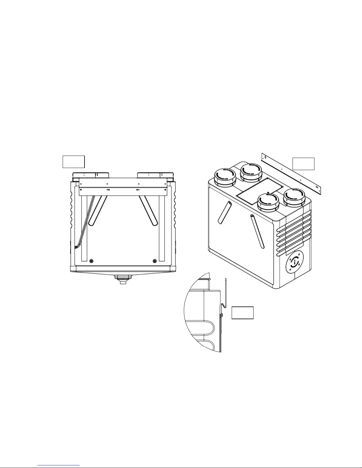
The aircycle 1.2 models AS 90-0102-WIN-01, AS 90-0102-WIN-01V, AS 90-0102-WINS-01,
and AS 90-0102-WINS-01V are designed for Wall Mounting only. The unit should be
attached the to the wall as shown using the wall bracket provided, please ensure the
mounting surface can safely bear the load of the unit using suitable screw fixings.
One bracket will be secured to the back of the unit as shown in Fig. 1, the second bracket
should be secured to the mounting surface as shown in Fig. 2. Please ensure the brackets
are level. The unit can then be set onto the mounting surface with the lip of each bracket
intersecting as shown in Fig. 3
Fig. 1
Fig. 2
Fig. 3
Page 14
13
V. 1.2-14-03-17
brookvent.co.uk
www.brookvent.co.uk T: +44 (0) 28 9061 6505
4.12 CEILING MOUNT
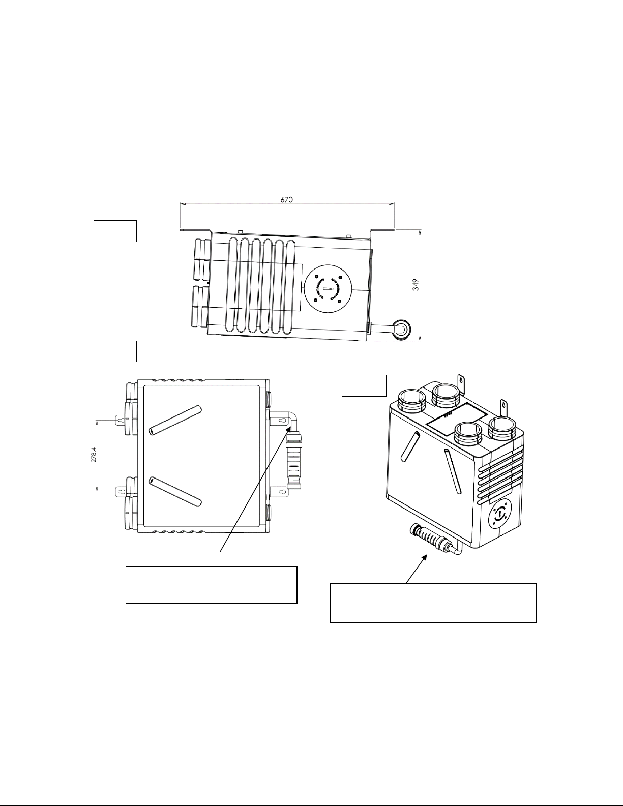
The aircycle 1.2 models AS 90-0102-CIN-01, AS 90-0102-CIN-01V, AS 90-0102-CINS-01,
and AS 90-0102-CINS-01V are designed for ceiling mounting only.
The unit should be attached to the Ceiling as shown (Fig.1) by first fixing the bracket to
the unit using the fixings provided.
Fig. 1
Fig. 2
Fig. 3
Brookvent supply drainage to this
point.
Dry Trap (Not Incl.) must be fitted with a 10
degree fall. Trap not included.
Page 15
14
V. 1.2-14-03-17
brookvent.co.uk
www.brookvent.co.uk T: +44 (0) 28 9061 6505
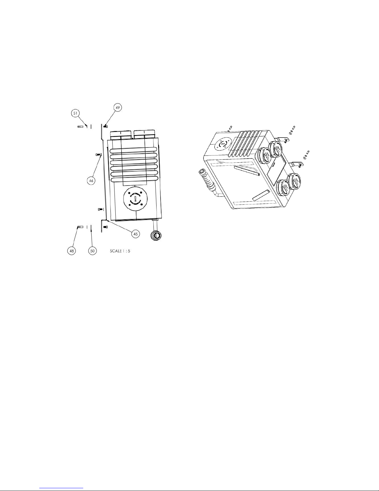
Also supplied are:
No.45 – Ceiling Mounting Bracket (Quantity: 2)
No.46 – M8 Anti Vibration Washer (Quantity: 7)
No.48 – M8 x 30 Celling Anchor (Quantity: 4)
No.49 – M8 x 16 Socket Cap Bolt (Quantity: 6)
No.50 – M8 x 24 Washer (Quantity: 2)
Please ensure that this method of fixing is suitable for the mounting surface and that it
can safely bear the load.
Page 16
15
V. 1.2-14-03-17
brookvent.co.uk
www.brookvent.co.uk T: +44 (0) 28 9061 6505
4.13 FLOOR MOUNT
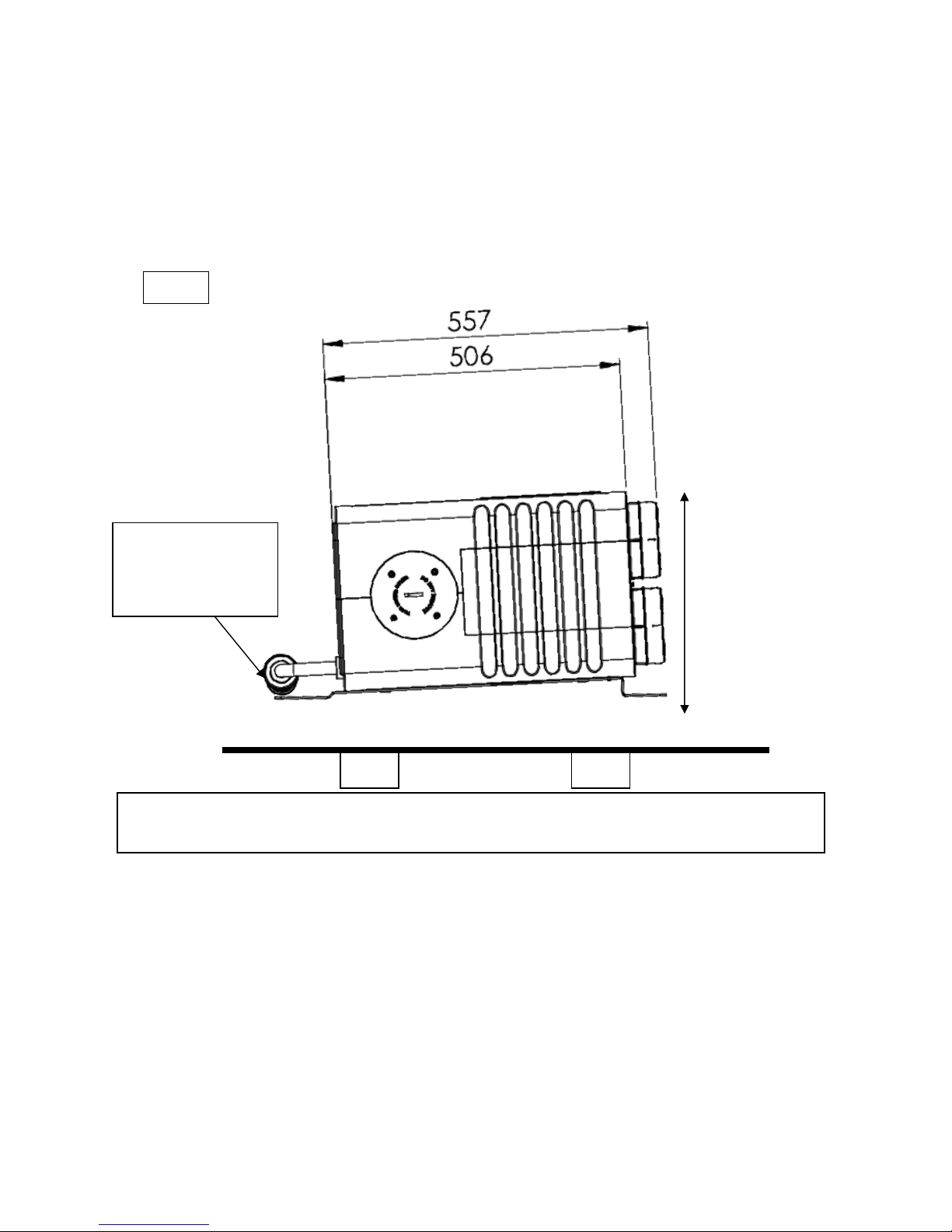
The aircycle 1.2 models AS 90-0102-FIN-01, AS 90-0102-FIN-01V, AS 90-0102-FINS-01,
and AS 90-0102-FINS-01V are designed for floor mounting only and comes complete with
its mounting bracket already fitted. The unit should be attached to the Floor, as shown,
mounted on a raised plinth. (Fig.1).
Please ensure that this method of fixing is suitable for the mounting surface and that it
can safely bear the load.
Fig. 1
349
NB. Dry trap (Not
Incl.) must be fitted
with a 10 degree fall.
Page 17

16
V. 1.2-14-03-17
brookvent.co.uk
www.brookvent.co.uk T: +44 (0) 28 9061 6505
4.2 Ductwork and Connections
To comply with SAP Appendix Q, and to facilitate the air flow performance, all ducting
used should be rigid. If flexible ducting is required, it should be kept to an absolute
minimum of 300mm and kept taut as per the Domestic Compliance Guide (Part F: Eng
and Wales 2010).
The spigots on the Brookvent aircycle 1.2 systems are suitable for connection to 125mm
diameter round pipe.
The label on top of the unit clearly identifies which spigot should be connected to which
ducting route within the dwelling. This is also shown clearly within this manual.
For optimum efficiency and performance, it is recommended that 125mm diameter
round pipe is used (where possible) to connect to the spigots and continue throughout
the dwelling, this will assist in keeping pressure losses to a minimum. A minimum straight
vertical run of 300mm should also be used directly off each spigot (where possible).
Where it is not possible to continue throughout the dwelling in rigid 125mm diameter
round pipe due to the void spaces available, a conversion to rigid 204mm x 60mm flat
rectangular ducting is recommended. It is recommended that the number of bends in the
ducting system is kept to a minimum.
Each of the external roof terminals / wall terminals must be the equivalent to the open
area of 125mm diameter round pipe.
To facilitate air circulation within the dwelling there must be a minimum of 10mm
undercut on each of the doors (to the finished floor) within the dwelling (or grills placed
at low level on the doors).
Extract air valves should be placed in all wet rooms (kitchen, utility, en-suite, etc.) and
should be sited, where possible, close to the main source of humidity/ pollutant.
Fresh supply air valves should be placed in all habitable rooms (bedroom, living room,
dining room, etc.).
Air valves should be locked upon commissioning so that they are tamper proof.
Duct designs/ layouts should always be adhered to if provided.
The Domestic Compliance Guide: Eng. and Wales 2010 or relevant equivalent dependent
upon local guidelines, should be adhered to in terms of installation practices.
Page 18
17
V. 1.2-14-03-17
brookvent.co.uk
www.brookvent.co.uk T: +44 (0) 28 9061 6505
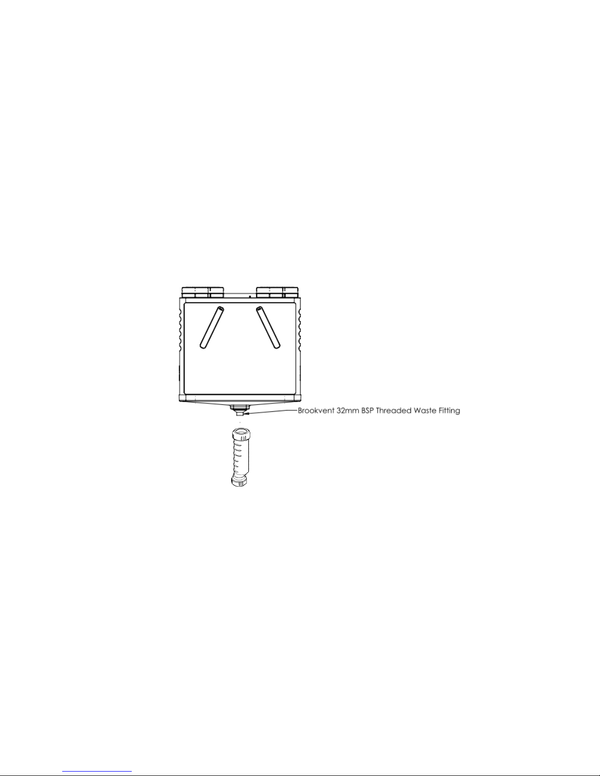
4.3 Connection of Condensate Drain
4.31 WALL MOUNT
Models: AS 90-0102-WIN-01, AS 90-0102-WIN-01V, AS 90-0102-WINS-01, and AS 90-
0102-WINS-01V
HRV systems generate considerable amounts of moisture due to their high Heat
Recovery Efficiency; this moisture must be drained from the system to a suitable
discharge location.
The aircycle 1.2 is supplied complete with a centralised drainage connection on the
bottom of the unit.
Brookvent recommend the use of a 32mm “Waterless Dry Trap” on HRV systems (as
shown above) to prevent the back flow of air into the HRV unit from the waste discharge
system.
It is imperative that there is a gravitational fall from the unit to the discharge point
ensuring that the water drains from the unit. A minimum fall of 5 Degrees should be
ensured throughout. Drainage piping/ connections should be insulated if located in cold
roof spaces. NB. Dry trap (Not Incl.) must be fitted with a 10 Degree fall at that point.
Drainage piping/ connections should be insulated if located in cold roof spaces.
DO NOT connect other condensate pipes from the system or other systems BEFORE the
“Waterless Dry Trap”
Page 19
18
V. 1.2-14-03-17
brookvent.co.uk
www.brookvent.co.uk T: +44 (0) 28 9061 6505
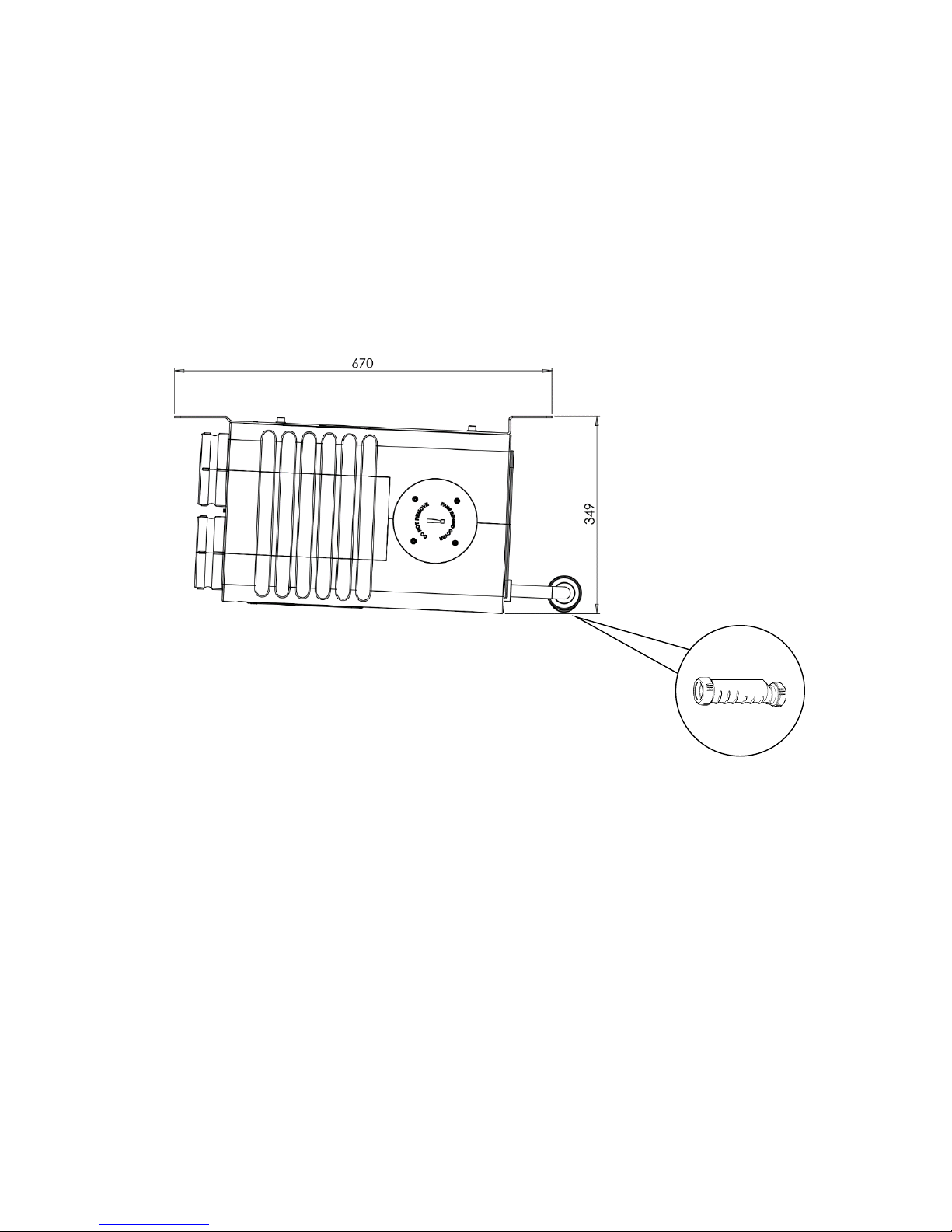
4.32 CEILING MOUNT
Models: AS 90-0102-CIN-01, AS 90-0102-CIN-01V, AS 90-0102-CINS-01, and AS 90-0102-
CINS-01V
HRV systems generate considerable amounts of moisture due to their high Heat
Recovery Efficiency; this moisture must be drained from the system to a suitable
discharge location.
The aircycle 1.2 Ceiling mount drainage connection is 21.5mm.
Brookvent recommend the use of a 32mm “Waterless Dry Trap” on HRV systems (as
shown above) to prevent the back flow of air into the HRV unit from the waste discharge
system.
It is imperative that there is a gravitational fall from the unit to the discharge point
ensuring that the water drains from the unit. A minimum fall of 5 Degrees should be
ensured throughout. Drainage piping/ connections should be insulated if located in cold
roof spaces. NB. Dry trap (Not Incl.) must be fitted with a 10 Degree fall at that point.
Drainage piping/ connections should be insulated if located in cold roof spaces.
DO NOT connect other condensate pipes from the system or other systems BEFORE the
“Waterless Dry Trap”
Page 20
19
V. 1.2-14-03-17
brookvent.co.uk
www.brookvent.co.uk T: +44 (0) 28 9061 6505
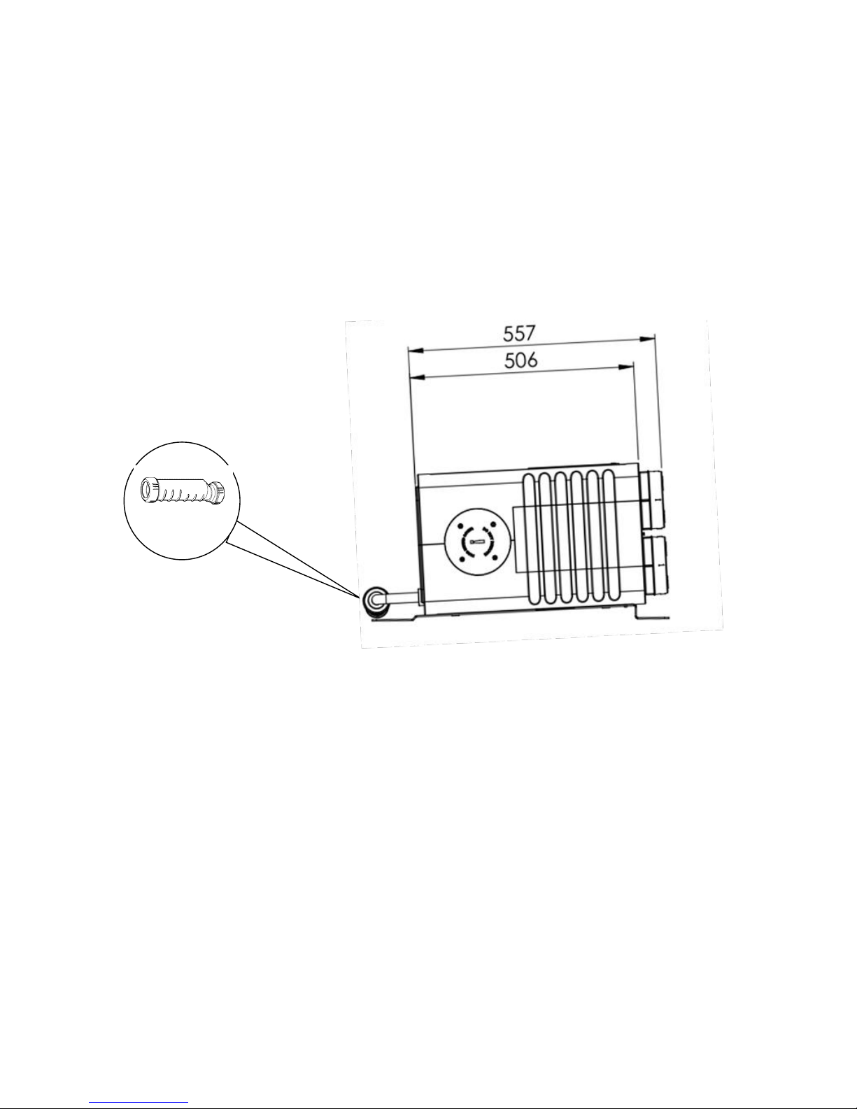
4.32 FLOOR MOUNT
Models: AS 90-0102-FIN-01, AS 90-0102-FIN-01V, AS 90-0102-FINS-01, and AS 90-0102-
FINS-01V
HRV systems generate considerable amounts of moisture due to their high Heat
Recovery Efficiency; this moisture must be drained from the system to a suitable
discharge location.
The aircycle 1.2 Floor mount drainage connection is 21.5mm.
Brookvent recommend the use of a 32mm “Waterless Dry Trap” on HRV systems (as
shown above) to prevent the back flow of air into the HRV unit from the waste discharge
system.
It is imperative that there is a gravitational fall from the unit to the discharge point
ensuring that the water drains from the unit. A minimum fall of 5 Degrees should be
ensured throughout. Drainage piping/ connections should be insulated if located in cold
roof spaces. NB. Dry trap (Not Incl.) must be fitted with a 10 Degree fall at that point.
Drainage piping/ connections should be insulated if located in cold roof spaces.
DO NOT connect other condensate pipes from the system or other systems BEFORE the
“Waterless Dry Trap”
Page 21

20
V. 1.2-14-03-17
brookvent.co.uk
www.brookvent.co.uk T: +44 (0) 28 9061 6505
5.0 Electrical Connections/ Wiring
IMPORTANT
All the electrical connections must be carried out by a qualified electrician. Installations
and wiring must conform to current IEE regulations (UK), local or appropriate
regulations (applying to other countries).
Electrical Details:
Voltage: 230 V AC ~
Fuse rating: 5 A
Warning: This unit must be earthed.
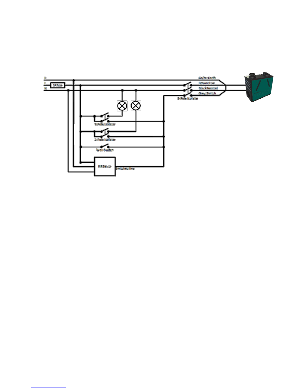
Please Note: The core cable from the mains power supply must be connected to a fixed
wiring installation, via a 5 amp fused isolator, as to comply with current IEE wiring
regulations.
A switch or circuit breaker must be used in the power supply circuit. It should be in close
proximity to the HRV unit and should be clearly marked as the disconnecting device for
the HRV Unit.
Connecting to mains:
The aircycle 1.2 unit comes pre-wired with 2m length of 4-core cable, which should be
connected into a fan-isolation switch. In turn a 3-core mains cable should be used to
connect to a 5A fused spur, which should be located close to the unit. The unit should
never be connected to a plug outlet.
Green/Yellow = Earth
Brown = Live
Black = Neutral
Grey = Switch
The grey switch wire is used to boost the system. When a live 230v signal is applied, the
Auto Boost function will be triggered.
Page 22
21
V. 1.2-14-03-17
brookvent.co.uk
www.brookvent.co.uk T: +44 (0) 28 9061 6505
5.1 Wiring Schematic
Page 23
22
V. 1.2-14-03-17
brookvent.co.uk
www.brookvent.co.uk T: +44 (0) 28 9061 6505
6.0 Controls and Settings
6.1 Fan Speed Control
The fan speeds of the unit are controlled by four potentiometers (Speed Pots) on top of
the unit; these are clearly marked “Trickle” and “Boost”. These allow individual control of
the trickle and boost rates for the supply and extract fans within the unit.
These separate speed options allow one speed to be set for normal day to day operation
(I.e. Trickle) and an increased speed to be set (I.e. Boost) that operates only when the
Grey switch wire is triggered by a 230v boost signal such as a Wall Switch or Passive
Infrared Sensor.
If the Boost for either fan is required to be set, it should always be set higher than the
Trickle. Turing these Speed Pots clockwise increases the fan speed.
Extract
Trickle
Extract
Boost
Supply
Trickle
Supply
Boost
Front
Humidity
60-100%
Boost
Over-run
0 – 15mins
NB. On standard configuration
systems the controls are located on
the RHS as shown. Inverted
configuration systems have their
controls located on the LHS and are
clearly labelled.
Page 24

23
V. 1.2-14-03-17
brookvent.co.uk
www.brookvent.co.uk T: +44 (0) 28 9061 6505
6.2 Commissioning Fan Speeds
1. Turn all 4 fan control spindles down fully to off (Extract Trickle, Extract Boost,
Supply Trickle, Supply Boost).
2. Turn the “Boost Over-run” to zero.
3. Turn the Boost Switch on (or trigger the boost by other means provided, e.g.
bathroom light switch relay if applicable).
4. Turn the Extract Boost spindle up until the minimum extract boost rate is
achieved in all the wet rooms (extract valves) as per the BPEC process for
commissioning.
5. Turn boost switch off (or other if applicable).
6. Turn the Supply Trickle up until the whole dwelling ventilation rate has been
achieved in all the habitable rooms (supply valves) as per the BPEC process for
commissioning.
NB: The trickle rate cannot be higher than the boost rate.
7. Turn the Extract Trickle up until the total airflow balances the total supply
trickle rate.
DO NOT ADJUST THE VALVES!
8. Turn the Boost Switch on (or trigger the boost by other means provided, e.g.
bathroom light switch relay if applicable).
9. Turn the Supply Boost up until the total airflow balances the total extract boost
rate.
DO NOT ADJUST THE VALVES!
10. Ensure that the whole system is commissioned correctly following the
procedures laid out by BPEC and the Domestic Compliance Guide (England and
Wales) – Part F – Means of Ventilation.
Commissioning is carried out to ensure that the required air flows are achieved
throughout the property. The volume airflow at each point should be measured using a
suitably calibrated Airflow Meter (anemometer), this is should be fitted with an adapter/
hood to ensure all air is captured and measured by the device.
For the required airflow rates refer to the design specification for the property and or
refer to Building Regulations (Part F: Means of Ventilation, England and Wales) or relevant
equivalent dependent upon local guidelines.
If further guidance is required on the commissioning process, please contact Brookvent
directly.
Page 25

24
V. 1.2-14-03-17
brookvent.co.uk
www.brookvent.co.uk T: +44 (0) 28 9061 6505
Example Commissioning:
Property – Area: 80sq.m Airtightness: less than 5cu.m/hr @
50Pa
Supply Rooms: Extract Rooms
Living 11l/s Kitchen 13l/s
Dining 5l/s Bathroom 8 l/s
Bedroom 8 l/s En-suite 8 l/s
Whole dwelling ventilation rate = 24l/s (the greater of Area x 0.3 or whole dwelling rate
table in building regulations).
Whole dwelling boost rate =29 l/s (the greater of the summation of the extract rates or the
whole dwelling rate).
As per the instructions above, turn all spindles down. Turn the boost switch on. Turn the
Extract boost spindle up until the extract boost rates are achieved (kitchen 13l/s,
bathroom 8l/s, En suite 8 l/s).
Lock the valves in place.
Turn the boost switch off. Turn the supply trickle spindle up to achieve the rates for the
supply rooms (living 11l/s, Dining 5l/s, Bedroom 8l/s).
Lock the valves in place.
Turn the Extract up down until the whole dwelling rate i.e. 24l/s is achieved through the
extract valves. Do not adjust the valves, only adjust the control on the unit.
Turn the boost switch on. Turn the Supply Boost up until the whole dwelling Boost rate
i.e. 29l/s is achieved through the Supply valves. Do not adjust the valves, only adjust the
control on the unit.
Turn the boost switch off.
Page 26

25
V. 1.2-14-03-17
brookvent.co.uk
www.brookvent.co.uk T: +44 (0) 28 9061 6505
6.3 Humidity Control
This potentiometer control is located on the front of the unit and can be adjusted by hand
and can be set between 60%-100% (Not active) relative Humidity, causing the unit to
boost when it senses the set humidity level. Adjusting the speed pot anti-clockwise will
cause the unit to become more sensitive thus boosting the system more often.
The factory setting for humidity is 70% RH. Turning this Speed Pot clockwise increases
the humidity level at which the unit will boost.
NB. Upon start-up/ power-on the humidity sensor will be inactive for a period of 60mins
due to calibration.
6.4 Boost Over-Run Timer
All Brookvent aircycle systems come complete with an automatic boost over-run timer of
15mins (factory set). The grey ‘switch wire’ on the aircycle 3.1 systems (See section ‘5.0
Electrical Connections/ Wiring’) is used to boost the system.
When a live 230v signal is applied by a switch or sensor, the boost function will be
triggered. When the signal stops, the boost will over-run for a minimum of 15 mins as to
ensure the system has adequately cleared the pollutants that were present. This is also
true for the internal humidistat feature in the aircycle 3.1.
The 15min boost over-run timer control is located on the front of the unit and can be
adjusted by hand and can be set between 0 mins and 15 mins by rotating the control
clockwise to increase the over-run timing.
6.5 Frost Protection
This is an automatic factory setting that causes the supply fan to turn off for 5 minutes
every hour when it senses temperatures below the 5 oC the set level allowing the warm
extract air from the home to pass though the core unaccompanied by the cold fresh in-
take air. This action succeeds in regularly raising the overall temperature within the Heat
Recovery System preventing the potential formation of ice particles which could cause
damage.
This feature is factory set, automatic, and requires no maintenance.
Page 27

26
V. 1.2-14-03-17
brookvent.co.uk
www.brookvent.co.uk T: +44 (0) 28 9061 6505
6.6 Tempering Summer Bypass
Feature available on selected models only (AS 90-0301-WINS-01).
The Tempering Summer Bypass feature, unique to Brookvent aircycle systems, functions
via thermostatically responsive solenoid which operates on a linear scale between 20
Degrees Celsius (No Summer Bypass) and 27 Degrees Celsius (Full Summer Bypass);
gradually increasing the amount of air directed around the Heat Recovery Core as the
temperature of the extract air from the home rises thus comfortably regulating the
indoor air temperature during warmer months.
This feature is factory set, automatic, and requires no maintenance.
Page 28
27
V. 1.2-14-03-17
brookvent.co.uk
www.brookvent.co.uk T: +44 (0) 28 9061 6505
7.0 Maintenance
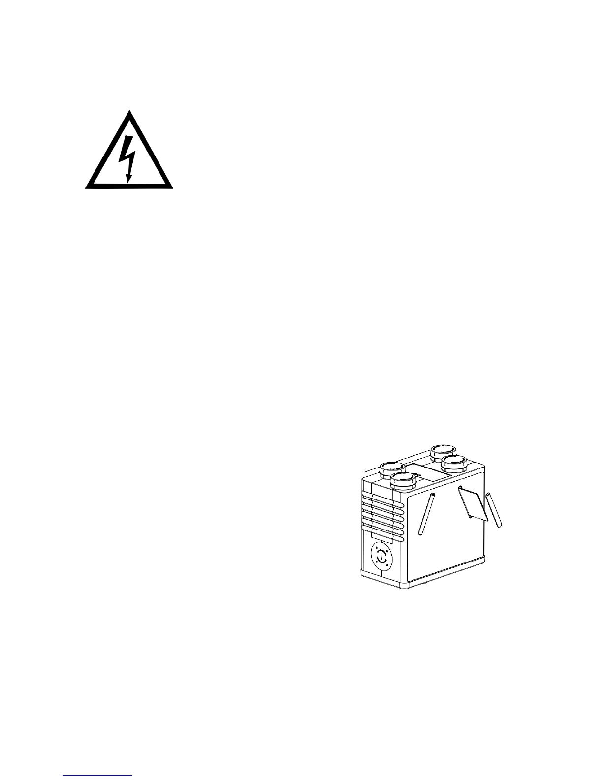
Warning: Dangerous Voltage. Before completing any form of
maintenance, ensure to isolate the unit from the mains and ensure all
supply circuits are disconnected.
This HRV unit may contain connections/signal wires from multiple electrical circuits.
ISOLATING THE CONTROL BOX WILL NOT ISOLATE ALL CIRCUITS WITHIN THE UNIT-
PLEASE ENSURE ISOLATION OF ALL CONNECTING CIRCUITS BEFORE ACCESSING THE
UNIT. Examples of other connecting circuits are: electric showers, lighting circuits, and
humidistats. These connecting circuits may be used to trigger the auto-boost the system.
It is important to follow all guidelines relating to the maintenance of this HRV system to
ensure the unit continues to perform to the levels required.
7.1 Filter Replacement
The filters of this HRV unit will usually need to be changed every 6 – 12 months depending
on occupancy/ use, and the type of environment the dwelling is located in (I.e. urban/
rural, and their associated levels of airborne
pollutants).
It is recommended that the filters are checked
every 6 months. Replacement filters can be
purchased online at brookvent.co.uk
To change the filters, simply remove the filter
covers from the front of the unit, replace the filters,
and replace the filter covers firmly.
Important: Blocked filters will shorten the life span
of your fan and increase the energy consumption. Never run the HRV system without
filters as this will allow unfiltered material to build up in the heat recovery core and
connected ductwork. In new build properties it may be prudent to check/ change your
filters after the first 3 months of occupancy depending on the amount of residual ‘building
dust’ present within the property
Page 29

28
V. 1.2-14-03-17
brookvent.co.uk
www.brookvent.co.uk T: +44 (0) 28 9061 6505
7.2 Additional Maintenance Checks
It is recommended that the following checks are also made when completing annual
maintenance of the HRV unit:
Condensate Drain: Ensure the condensation drain is firmly secured and is clear of
any debris, remove/ clean if necessary.
Fixings: Ensure that all of the unit fixings and the mounting fixings have not
become loose over time and are kept sufficiently tight.
Page 30

29
V. 1.2-14-03-17
brookvent.co.uk
www.brookvent.co.uk T: +44 (0) 28 9061 6505
8.0 User Operation
The Brookvent aircycle 1.2 is an extremely compact and highly efficient Mechanical Heat
Recovery Ventilation (HRV/MHRV) system, specifically designed for smaller dwellings and
apartments with restricted space.
The system should be run continuously 24 hours a day, and should only be disconnected
by a competent person during service or maintenance.
The system works by drawing stale air from ‘wet rooms’ such as Bathrooms, WC’s and
Kitchens, recovering up to 93% of the heat from this air using a highly efficient heat
exchanger, before expelling the waste air outside the home. Simultaneously, fresh air is
drawn into the home, filtered and warmed by the recovered heat and supplied into the
‘habitable rooms’ such as bedrooms, dining rooms and living rooms.
How your system is configured upon installation will influence how it can be operated at
the user level. Please ensure to refer to the commissioning certificate provided by your
installer for full details.
General Guidance
Your system may be set up to boost from trickle speed automatically via sensors (e.g.
Passive Infrared Sensors) or manually via simple switch controls. These may be timed
switches or push/pull switches. Boost options, if provided and if required, should be used
when excess pollutants are being generated within the home (Cooking, Bathing etc.)
With certain dwellings the system may be configured to operate at what is known as a
“constant ventilation rate”. This means that there is no boost required to adequately
ventilate the home and the system operates at one set level at all times requiring no user
input/control.
Page 31

30
V. 1.2-14-03-17
brookvent.co.uk
www.brookvent.co.uk T: +44 (0) 28 9061 6505
8.1 Typical Automatic Control Options
Your system commissioning certificate completed by your system installer should
detail your automatic control options (if any).
Passive Infra-red (PIR) Sensors
These are motion sensing switches; these sensors trigger the system into boost mode
when activity/ motion is detected in a particular room. They are typically put into sanitary
accommodation or bathrooms.
Humidistat
These sensors detect humidity in the air and trigger the system into boost mode when
humidity reaches a certain level. These are typically placed in bathrooms or in kitchens.
Please note that the aircycle 1.2 system has an In-built humidistat that operates in the
same fashion.
Light switch
The lighting circuit of the home can be used to boost the system meaning that when the
occupier enters the room and turns the on the light, the system is triggered into boost
mode. This is typically used in sanitary accommodation and bathrooms.
*The items detailed above are examples of the types of Automatic Control Options that
are typically used in conjunction with the Brookvent aircycle 1.2*
Page 32

31
V. 1.2-14-03-17
brookvent.co.uk
www.brookvent.co.uk T: +44 (0) 28 9061 6505
8.2 Typical Manual Control Options
Your system commissioning certificate completed by your system installer should
detail your manual control options (if any).
Spring loaded switch
This switch may be placed in any room within the house; however, it is typically used in
sanitary accommodation, bathrooms and or kitchens. When pressed, it will trigger the
system into boost mode for a defined time.
Trickle and Boost switch
This is a simple on-off switch with no determined time delay. When the switch is flicked
to boost the system goes into its boost state, the switch then must be put back to trickle
by the occupier for standard operation. (Please note that the aircycle 1.2 system has a
minimum boost overrun time of 15mins).
*The items detailed above are examples of the types of Manual Control Options that are
typically used in conjunction with the Brookvent aircycle 1.2 *
Page 33

32
V. 1.2-14-03-17
brookvent.co.uk
www.brookvent.co.uk T: +44 (0) 28 9061 6505
9.0 Trouble Shooting
The unit is not running?
Check that the unit is connected to a 5amp fused spur.
Check that there is a live feed to the fused spur.
Check that the 5 amp fuse has not tripped/blown.
Check that all the spindles are in the full power position (the fans take a few seconds to
start up.
The system is constantly in Boost?
New houses can be quite damp with items drying out; this can cause the inbuilt
humidistat (and external humidistats) to activate. The in-built humidistat is disabled for
the first hour after set up; however, if the system is boosting after this period the level
can be adjusted to 100% effectively switching off the humidistat. Remember to turn this
stat down again after commissioning.
Check whether the system is designed to boost from a light switch relay, if so, have any
of these been left on while commissioning process is being carried out.
Page 34

33
V. 1.2-14-03-17
brookvent.co.uk
www.brookvent.co.uk T: +44 (0) 28 9061 6505
Notes
Page 35

34
V. 1.2-14-03-17
brookvent.co.uk
www.brookvent.co.uk T: +44 (0) 28 9061 6505
Notes
Page 36

35
V. 1.2-14-03-17
brookvent.co.uk
www.brookvent.co.uk T: +44 (0) 28 9061 6505
Customer Support
At Brookvent we pride ourselves on providing Gold Standard after sales and support to
all customers. Please feel free to contact one of our specialist team about any query you
may have and we will be more than happy to assist you.
Brookvent
Brook House,
Dunmurry Industrial Estate,
Dunmurry,
Belfast
Northern Ireland, BT17 9HU
T: +44 (0) 28 9061 6505
It is important to retain this manual and make a copy available to any person using or
working with (maintaining) the system.
Brookvent operate a policy of continuous innovation and improvement and thus
reserve the right to alter product specifications and appearances without notice.
 Loading...