

Page 1
airplus 1.1E Last updated 26-03-13 Page 1 of 12
Positive Input Ventilation
Applicable to airplus 1.1E
Installation and User Maual
Instructions for the Installer,
Maintenance Engineer and End User
Page 2

airplus 1.1E Last updated 26-03-13 Page 2 of 12
PLEASE KEEP THESE INSTRUCTIONS WITH THE PRODUCT.
Please read this manual fully prior to installing the PIV unit
airplus Kit - Box Contents:
1 qty airplus fan unit
1 qty Thermostat
1 qty White G4 Filter
1 qty Diffuser Assembly
1 qty Blanking Strip (30mm x 370mm)
4 qty 30mm Pieces Hook & Loop tape
2 m Flexible Hose (125mm Dia)
2 m Black Nylon Cord
IMPORTANT:
This appliance is not intended for use by persons (including children) with reduced physical
sensory or mental capabilities, or lack of experience and knowledge, unless they have been
given supervision or instruction concerning use of the appliance by a person responsible for
their safety.
Contents:
1. Introduction
1.1. Product Guarantee
2. Safety
2.1. General Safety
2.2. Installer Responsibilities
2.3. Occupant Responsibilities
3. Technical Specification
3.1. General Specification
3.2. Performance characteristics
4. Installation & Wiring
4.1. Mounting
4.2. Ductwork and Connections
4.3. Electrical Connections/ Wiring
5. Maintenance
5.1. Filter Replacement
5.2. Additional Maintenance Checks
6. Commissioning
6.1. Install Check List
6.2. Service Record
Page 3

airplus 1.1E Last updated 26-03-13 Page 3 of 12
1 Introduction
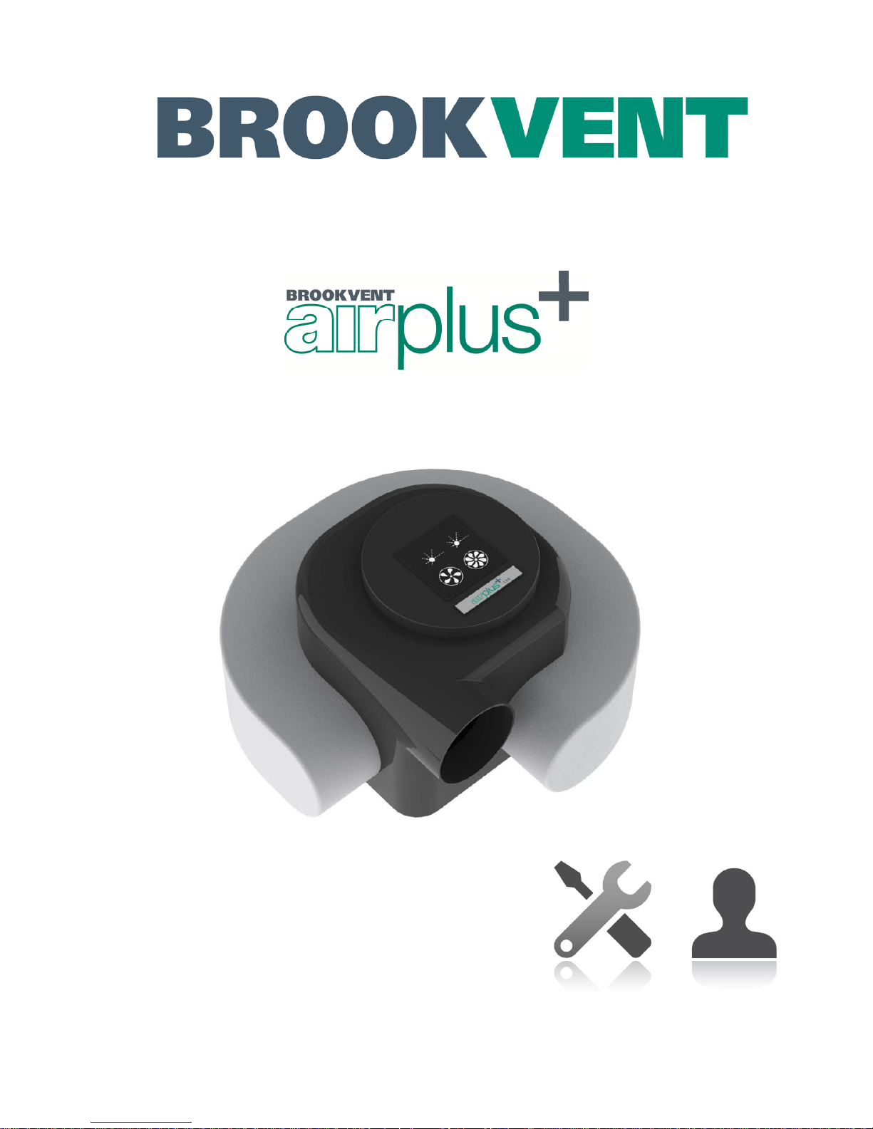
The Brookvent Airplus 1.1 E is an extremely compact and efficient Positive Input Ventilation
(PIV) system, specifically designed to offer moisture control in buildings to prevent/control
condensation issues.
The system should be run continuously 24 hours a day, and should only be disconnected by
a competent person during service or maintenance.
PIV works best in homes with good background ventilation – the system draws air from the
roof space through a G4 pollen filter, and gently supplies this air into the main hallway
(usually upstairs).
As the system pressurises the home, moisture laden air is forced out of the home through
purpose provided ventilation (window vents) and natural leakage. This constant movement
of air through the home helps to control condensation and keeps the air in the home fresh.
The system will run at a constant speed which set during install. If the attic temperature
exceeds the pre-set temperature on the thermostat, the system will drop to a low rate to
prevent over heating of the dwelling.
There is no user interface with the system which is maintenance free, other than a filter
change every 5 years.
1.1 Product Guarantee
This product is guaranteed against defects for a period of 5 years from date of purchase.
With the first year covering parts and labour, and the remaining 4 years covering parts only.
In the instance of such a defect, Brookvent may, at its absolute discretion, repair the product,
replace the product free of charge or refund the cost of the product.
In terms of installation, operation and maintenance, please follow all instructions provided, if
this product has been misused or handled carelessly it may lead to the guarantee being
declared void.
Brookvent does not accept any liability for damage caused by non-observance of the
installation instructions. Service activities must be carried out by Brookvent or by registered
installers using original Brookvent parts.
This guarantee does not affect your statutory right as a consumer.
Page 4

airplus 1.1E Last updated 26-03-13 Page 4 of 12
2 Safety
The following information must be read carefully to ensure safe installation and operation of
the Brookvent PIV system.
2.1 General Safety
• Do not use this appliance for functions other than those described in this booklet.
• Never touch the appliance with wet hands.
• The unit is only suitable for 230 V AC/50Hz electric mains.
• Never modify the fan or electronics, all repairs must be conducted by Brookvent.
• Never connect the power if the electronics enclosure is open.
• Do not store inflammable products in the neighbourhood of the unit.
2.2 Responsibility of the Installer
• Correct Installation and commissioning of the PIV unit.
• Record measured air flow at the supply valve.
• Compliance to requirements and local additional rules.
• Explanation of the ventilation system to the user.
• Warning for the user, to check or replace the air filters on time.
• All the above, as set out in the latest edition of the Domestic Ventilation Compliance
Guide and the Appendix Q – Installation Guide and Checklist.
2.2 Responsibility of the Occupant
• Replacement of the filters every 5 years by contacting Brookvent for a replacement.
• Cleaning the supply valve regularly to prevent blockage.
• To ensure that the system is functioning properly by periodically checking the airflow
• To ensure the system is always left on unless serviced by an authorised person.
IMPORTANT: Dirty or clogged filters may cause inadequate ventilation in the home which
may lead to health issues. It is important that the filters are changed after 5 years or sooner
if required.
Page 5
airplus 1.1E Last updated 26-03-13 Page 5 of 12
3 Technical Specification
3.1 General Specification
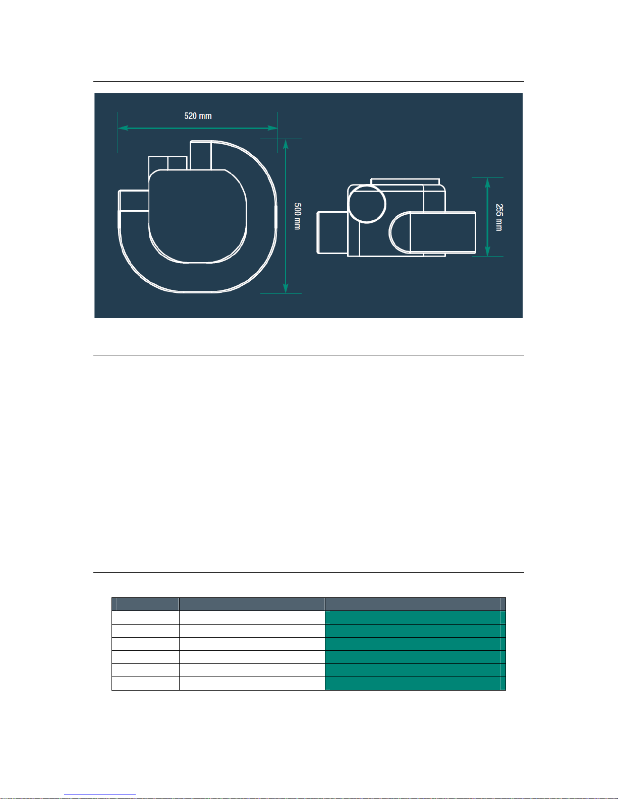
Dimensions: 520mm x 500mm x 255mm
Weight: 4kg
Materials: Main Enclosure: ABS
Electronics Enclosure: ABS – V0 rated
Filter: G4 Rated - Polyester Fibres
Electrical: 230/240V AC
Function: Low rate Thermostat controlled, 100% variable
Recommended set-up (20l/s) active < 23°c > low (5l/s)
Fully complies with Building Regulations for UK & Ireland.
3.2 Performance Characteristics
L/S Fan Speed Setting
Specific Fan Power (w/l/s)
21 100% Variable Speed
0.17
29 100% Variable Speed
0.16
37 100% Variable Speed
0.17
45 100% Variable Speed
0.18
53 100% Variable Speed
0.22
61 100% Variable Speed
0.24
Page 6
airplus 1.1E Last updated 26-03-13 Page 6 of 12
4.0 Installation
It is important that the full installation of this system is carried out by competent persons,
including all electrical works and connections being completed by a qualified electrician.
The PIV unit is designed to be installed indoors, within the attic space, away from exposure
to frost, water, or intense heat.
A clear access space is required around the unit; this will ensure ease of installation relating
to ductwork and wiring. This will also ensure ease of future maintenance to the system.
4.1 Assembly & Mounting
Fit Filter:
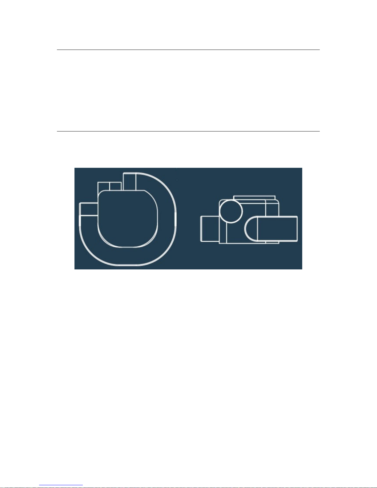
To assemble the airplus unit, first take the white filter and fit over the 4 inlet spigots, as
shown. The elastic should be tight and hold the filter securely in place.
Mounting:
The airplus 1.1 can be mounted in 2 different positions depending on requirements.
a. Suspended: Recommended
Using the black nylon cord provided, suspend the unit from screws fitted to a roof joist,
approximately 1/3rd down from the highest point in the attic space. This is to maximise the
heat recovery from the attic into the dwelling.
The electronics enclosure may be placed on top of the airplus unit or screwed to a roof joist.
b. Floor Mount:
Mount a 1” plywood plinth to the floor joists securely and fasten the airplus unit to the plinth
securely using suitable screws. This mounting position does not offer optimum heat
recovery and may transfer noise from the fan to the joists.
Diffuser:
The ceiling diffuser should be cited in the centre of the hallway, but away from the access
hatch, light fitting(s) and smoke detectors. Drill a 125mm hole through the ceiling using a
core-cutter, taking care to avoid joists and electrical wiring. Attach the diffuser body to the
ceiling using 4 drywall screws (not supplied) and clip the diffuser cover in place.
IMPORTANT: If the diffuser is within 1.5m of a smoke detector, use the supplied blanking
strip to block diffuser openings as required, to prevent the supply air from blowing across the
smoke detector.
Page 7
airplus 1.1E Last updated 26-03-13 Page 7 of 12
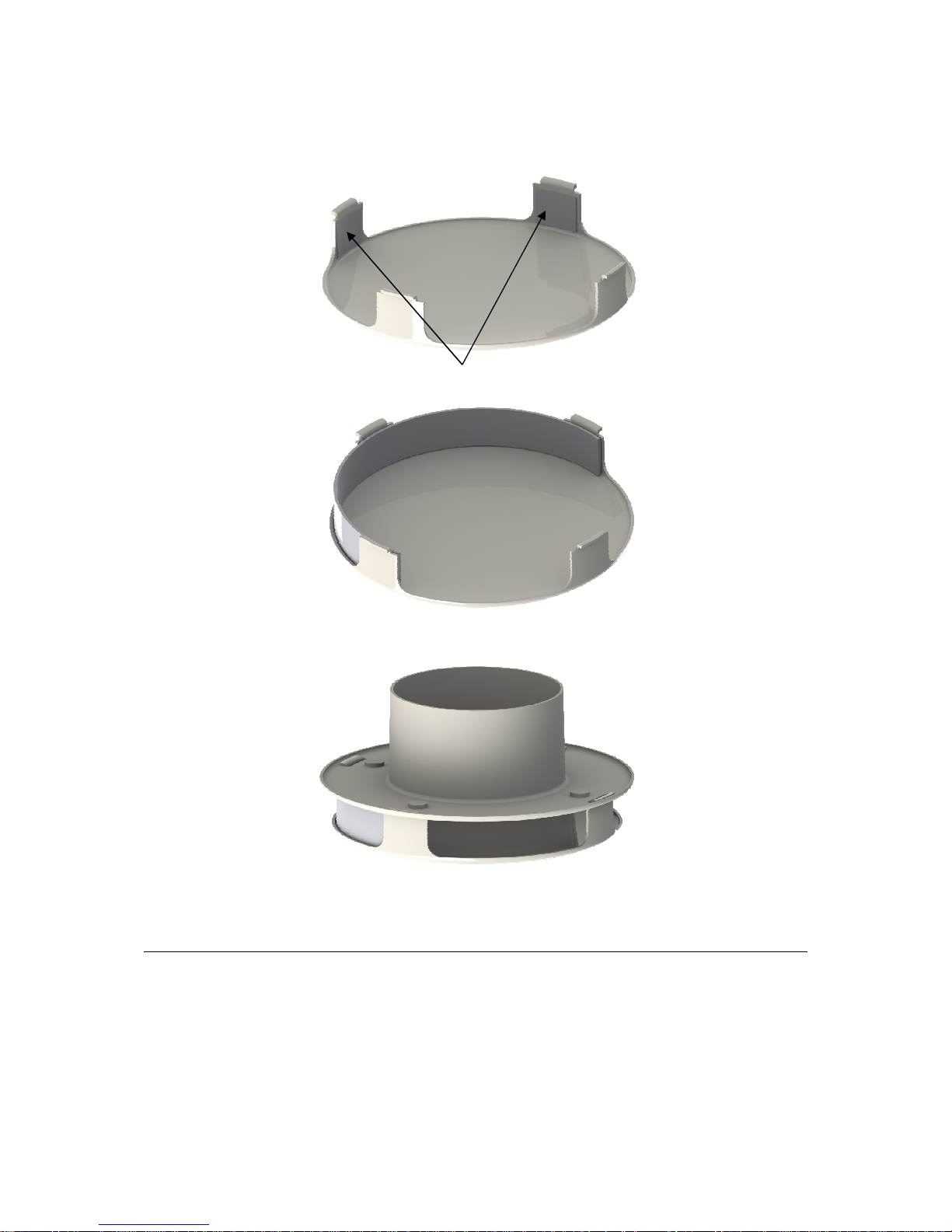
Blanking strip can be cut to length and held in place with the hook and loop tape as shown.
Fig 1. Add Velcro Tabs to diffuser cover where required
Fig 2. Fit Blanking strip (block 1 or 2 openings)
Fig 3. Diffuser cover fitted to diffuser body
4.2 Ductwork and Connections
Use the supplied 125mm flexible ducting, which should be cut to the minimum required
length to reduce pressure loss in the system.
Connect the ducting to the outlet on the unit and the diffuser opening, and seal with suitable
duct tape and / or sealant.
Page 8
airplus 1.1E Last updated 26-03-13 Page 8 of 12
4.3 Electrical Connections/ Wiring
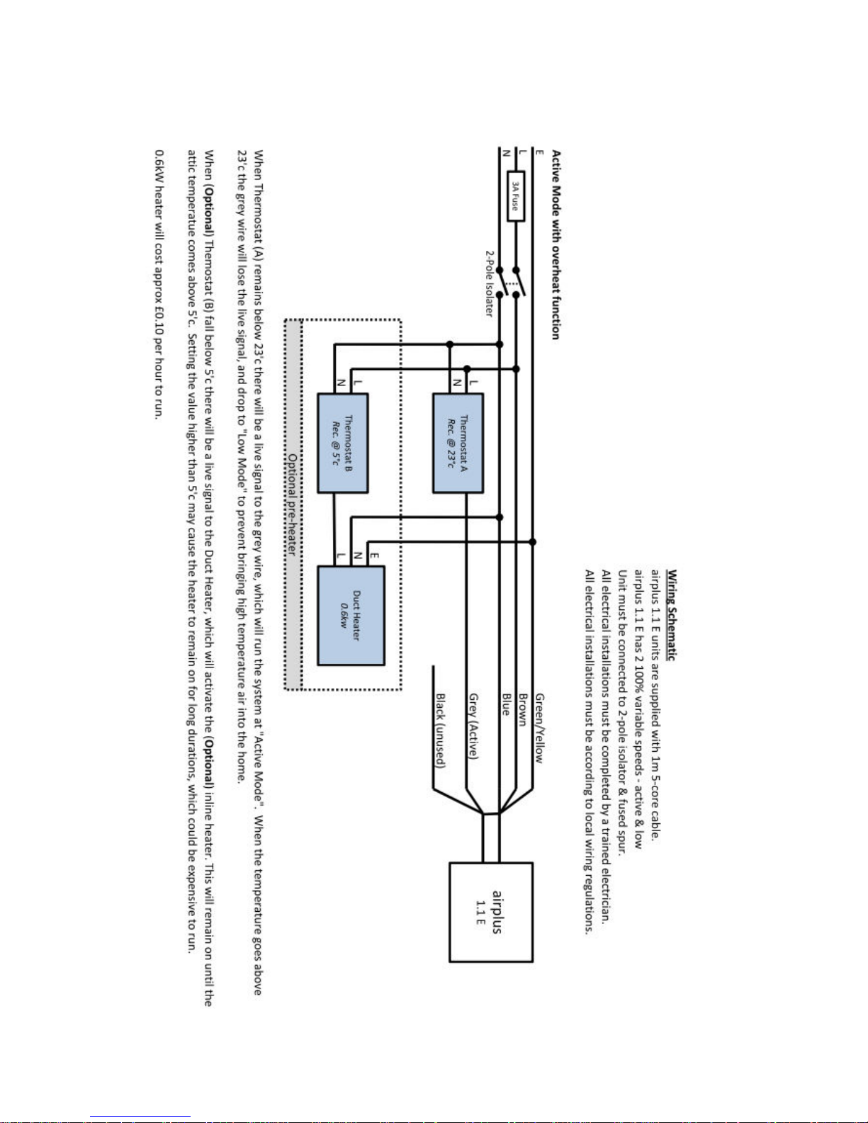
Important: All the electrical connections must be carried out by a qualified electrician.
Installations and wiring must conform to current IEE regulations (UK), local or appropriate
regulations (applying to other countries).
Electrical Details:
Voltage: 230 V AC ~ @ 50hz
Fuse rating: 5 A
Warning: This unit must be earthed.
Please Note: The three core cable from the mains power supply must be connected to a
fixed wiring installation, via a 5 amp fused isolator, as to comply with current IEE wiring
regulations. A suitably rated mains supply cable must be used.
A 5A switch or circuit breaker must be used in the power supply circuit. It should be in close
proximity to the PIV unit and should be clearly marked as the disconnecting device for the
PIV Unit.
IMPORTANT: Never open the fan unit as this will invalidate your warranty.
Mains Input:
A standard 3 core 240v AC mains cable must be used to connect the unit to the domestic
mains supply. The connection must be isolated by a fused switch rated at 5 amps. The
switch must be located in the vicinity of the unit or according to local regulations.
First Commissioning:
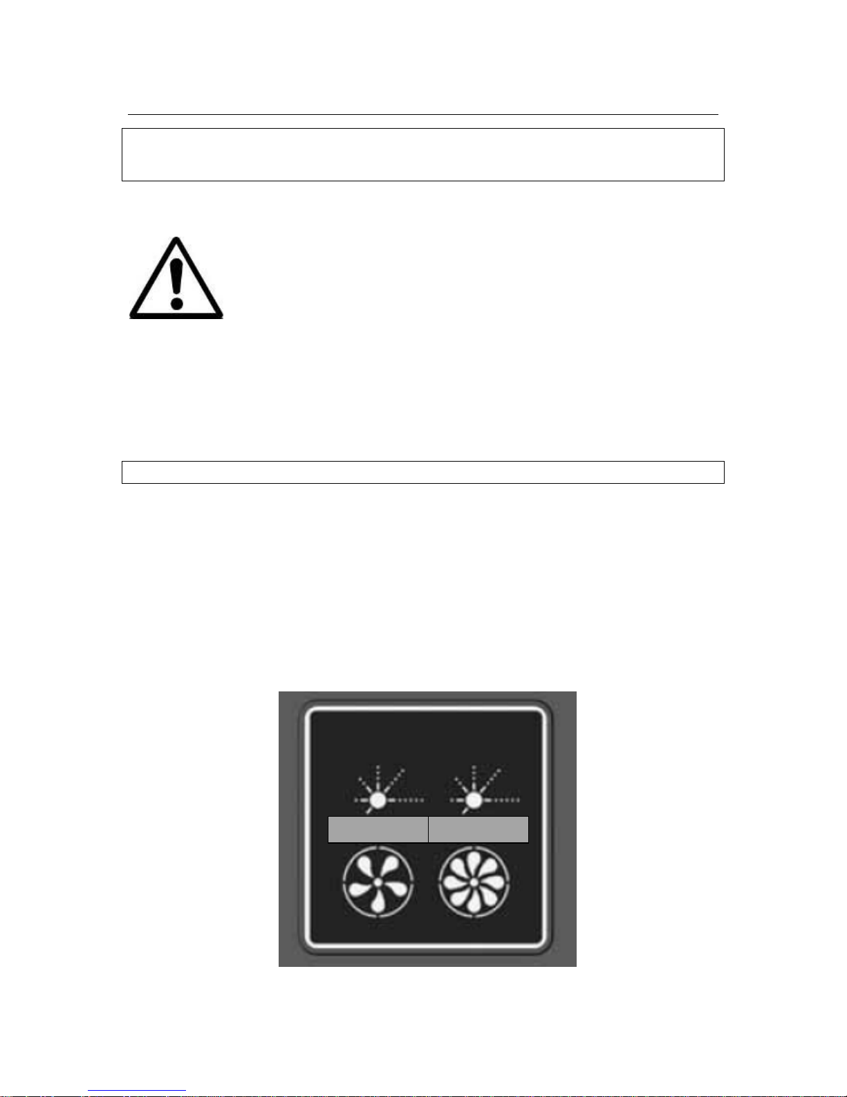
Use the speed dials to set the “active” and “low” rates, approx. 20l/s and 5l/s respectively.
Active:
20 l/s
Low:
5 l/s
Page 9

airplus 1.1E Last updated 26-03-13 Page 9 of 12
In normal operation the system will operate in “active” mode.
Set the thermostat to the temperature that the unit should automatically reduce down to the
low rate (recommended temperature setting is 23°c)
The thermostat should be placed in the attic space near the unit itself, to measure the air
temperature being drawn into the system.
When the attic temperature exceeds this value the fan speed will decease to the low rate to
prevent overheating of the dwelling.
Page 10
airplus 1.1E Last updated 26-03-13 Page 10 of 12
Wiring Schematic
Page 11
airplus 1.1E Last updated 26-03-13 Page 11 of 12
5.0 Maintenance
Warning: Dangerous Voltage. Before completing any form of
maintenance, ensure to isolate the unit from the mains and
ensure all supply circuits are disconnected.
It is important to follow all guidelines relating to the maintenance of this PIV system to
ensure the unit continues to perform to the levels required.
5.1 Filter Replacement
The filter of this PIV unit will usually need to be changed every 3-5 years depending on
occupancy, and the type of environment the dwelling is located in (I.e. urban/ rural, and their
associated levels of airborne pollutants).
It is recommended that the filter is visually checked every 12 months.
IMPORTANT: Always isolate the power to the unit before replacing the filter, as the fan
becomes accessible and may cause injury.
To remove the filter, pull one end over the spigot by stretching the elastic. The filter will come
away easily.
To replace the filter, place one end over the spigot directly next to the supply outlet. Pull the
free end to stretch the elastic over the last spigot, ensuring that all openings are covered by
the filter.
5.2 Additional Maintenance Checks
It is recommended that the following checks are also made when completing annual
maintenance check of the PIV unit:
• Filter check for excess dust / contaminants. If the filter appears very dirty, it may
require to be changed. Contact Brookvent to purchase a spare filter.
• Fixings: Ensure that all of the unit fixings and the mounting fixings have not become
loose over time and are kept sufficiently tight.
Page 12

airplus 1.1E Last updated 26-03-13 Page 12 of 12
BROOKVENT
Brook House
Dunmurry Industrial Estate
Dunmurry
BT17 9HU
T 028 90 616 505
F 02890616518
www.brookvent.co.uk
 Loading...