

Page 1
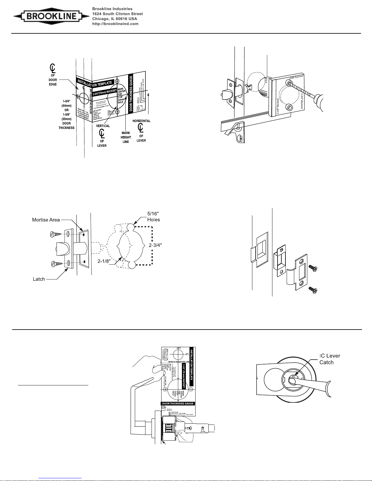
Figure 4
Figure 2
Figure 1
Figure 3
DOOR PREPARATION
INSTALL STRIKE
1. Align strike with latch.
2. Trace strike outline on door jamb.
3. Mortise jamb and install strike and dust box.
INSTALL LATCH
1. Drill 1" diameter hole for latch. Mortise for latch front. Insert latch and fasten with
two screws.
HOLLOW METAL DOORS
1. Must have horizontal and vertical lock and latch support provided by door
manufacturer.
1. With IC core removed, use screwdriver inside lever
to depress lever latch.
2. Pull off lever.
To Adjust For Other Door Thickness:
Remove outside lever.
DOOR PREPARATION
Split Spacer
(8mm)
(70mm)
(54mm)
C300 SERIES Grade 1 Cylindrical Key in Lever
Installation Instructions I-C300-2013-01
1. Fold and apply template to high edge of door at desired height from
floor. 2. Mark hole centers on door and door edge.
3. Drill 5/16" (8mm) thru-bolt holes first, then drill 2-1/8" (54mm) hole.
NOTE: It is important that both 1" (25.4mm) and 2-1/8" (54mm) holes be
on the same horizontal center line.
2. If 2-1/8" (54mm) hole exists, use optional an Installation aJig
to ensureaccurate drilling of 5/16" (8mm) thru-bolt holes.
DOOR THICKNESS ADJUSTMENT
Figure 5
1. Locks are factory assembled with a ring for 1-3/4"
(44mm) thick door. Locks can be adjusted for
1-5/8"(44mm) to 1-7/8"(48mm) door thickness.
2. Before installation, use door thickness gauge on
template as shown in Fig. 5, to check lock chassis
position. Center of latch retractor should align with
mark on gauge for appropriate door thickness.
If chassis is not on center, screw chassis in or outto
align with mark. Check that lever engages lever
catch before installation. If adjusting for doors
less than 1-3/4"(44mm) thickness, the split
spacer must be removed.
3. Reinstall outside lever.
How To Remove IC Lever (Fig. 6):
I-C300-2013-01 Page 1
Page 2
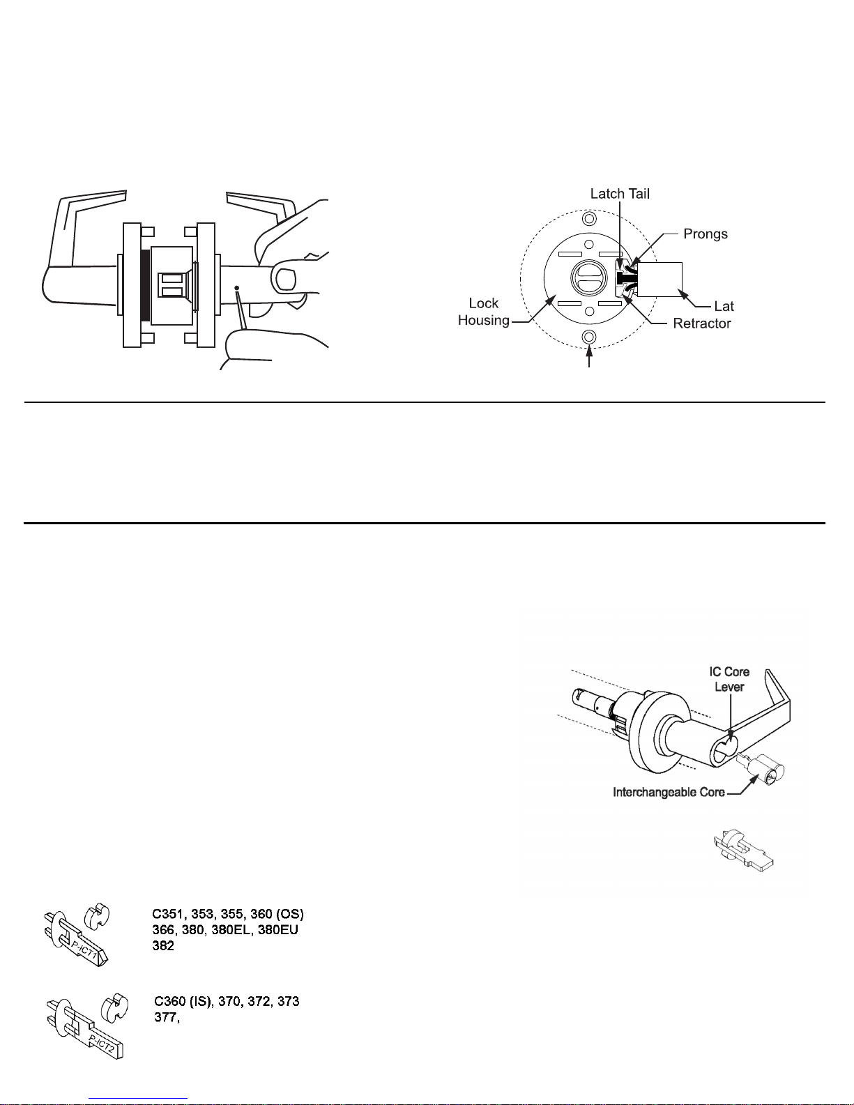
2. Prongs must engage inside lock housing.
3. Align outside rose so rose posts enter thru-bolt holes
in door.
4. Check from inside of door to see if latch is properly engaged.
INSTALL INSIDE TRIM:
1. Replace inside rose assembly and fasten to outside rose
with the two long thru-bolts.
2. Press rose cover over inside rose. Notch in cover must
align with either notch on inside rose.
1. Remove inside lever. Depress the lever catch with the wire
pin through the small hole in the rose/lever and pull lever
off the tube.
2. Depress lever catch again and remove the inside rose
assembly.
INSTALL LEVER:
1. Press lever on lock tube, slightly wiggle and push until
lever engages lever catch and connector prongs.
2. Test lever to be sure it is on securely.
IC CORE CYLINDER: Removal (all functions)
1. Insert control key and turn clockwise, then pull on
key to remove core.
1. Insert screwdriver into key cam slot in tube and
turn fully clockwise.
DB Function
1. Using a screwdriver, place the tip into the key cam
slot and turn counter-clockwise as far as possible.
When at the maximum counter-clockwise position,
turn clockwise 90°. Insert outside IC core cylinder
into lever.
2. Test to see that timing is correct for both inside and
outside levers.
T Function
1. Insert screwdriver in key cam slot and turn fully clockwise
without retracting latch. Now turn counterclockwise 45°.
Remove screwdriver.
Correct orientation of spacer for
conversion of 7 pin tailpiece for
use with 6 pin ic core.
INSTALLING THE LOCK
Rose Posts
chbolt
PREPARE LOCK (Fig. 7):
Figure 7
INSTALL LOCK (Fig. 8):
1. Push lock through 2-1/8" (54mm) hole from the
outside so that retractor engages latch tail.
Figure 8
CHANGE/REPLACE IC CORE CYLINDER
Installation of Core for Functions
351, 353, 355, 360 (Outside) 380, 382
1. Insert control key in core and turn clockwise.
2. Insert tailpiece P-ICT1 in core.
3. With control key in core, insert core fully into lock.
4. Turn key counter-clockwise and remove key.
360 (Inside) 370, 372, 373, 377
2. Insert control key in core and turn clockwise.
3. Insert tailpiece P-ICT2 in core.
4. With control key in core, insert core fully into lock.
5. Turn key counter-clockwise and remove key.
IC Tailpieces
IC Keyed Functions
2. Insert control key in core and turn clockwise.
3. Insert tailpiece P-ICT2 in core.
4. With control key in core, insert core fully into lock.
5. Turn key counterclockwise and remove key.
Figure 9
Brookline Industries • 1624 South Clinton Street • Chicago Illinois 60616 USA • http://brooklineindustries.com
I-C300-2013-01 Page 2
 Loading...