

Page 1
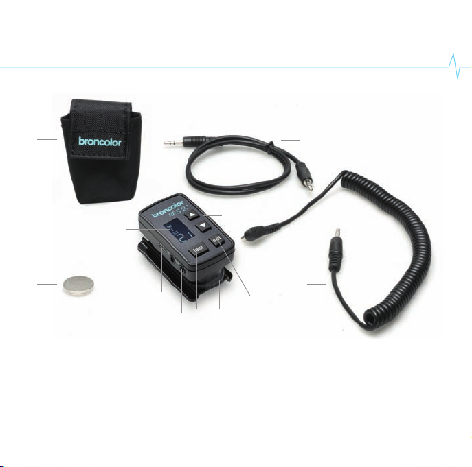
SCOPE OF DELIVERY
1
2
1 Case
2 lithium button cell
3 Display
4 USB socket
5 Sync in
6 Sync out
2
3
4
5
Li-Mn CR2450 (560 mAh, 3 V)
11
10
12
9
7 8
6
7 "test" key
8 Base plate (only with receiver kit)
9 "set" key (to set lamp channel and studio channel)
10 Keys "
11 Sync cable for flash unit mini to mini (only with receiver kit)
12 Sync cable for camera
", "" (to regulate the flash energy and for
adjustment of the lamp channel and studio address)
Page 2
14
13
15
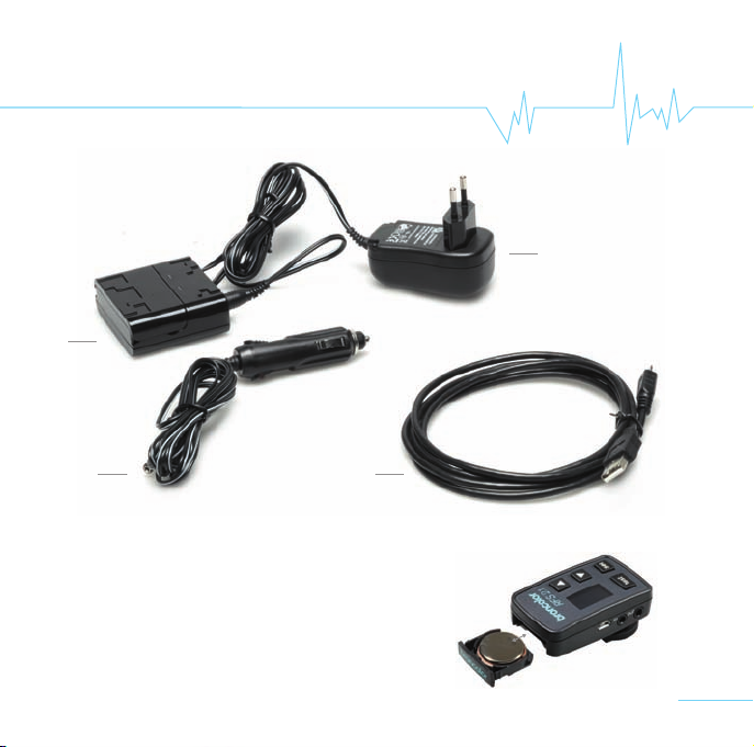
13 Rechargeable battery pack for receiver operation
(incl. rechargable batteries)
14 Power supply device (only with receiver kit)
15 Charge cable (for use in car) (only with receiver kit)
16 USB cable (only with receiver kit)
16
3
Page 3
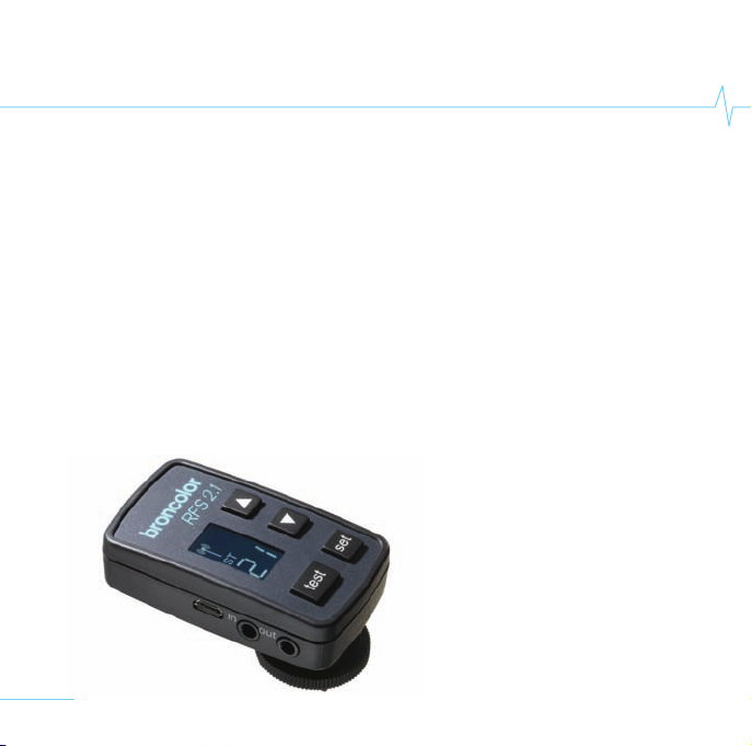
BRONCOLOR RADIO FREQUENCY SYSTEM 2.1
Before use
We are ve ry pleased you have chosen a broncolor Radio Frequency System
RFS 2.1 unit, which is a high-quality product in every respect. If used properly,
it will render you many years of good service. Please read the information
contained in these operating instructions carefully. They contain important
details on the use, safety and maintenance of the device. Keep these operating instructions in a safe place and pass them on to further users if necessary. They are also available online at www.broncolor.com.
With the broncolor RFS 2.1 you can trigger and operate by remote control
broncolor units, which are equipped with an integrated RFS 2 or RFS 2.1 interface.
4
Page 4
1.
OPERATION AS TRANSMITTER OR RECEIVER
The transceiver can be operated in two modes. The unit is always in transmitting mode when used in battery operation. The transceiver functions as
transmitter.
If the transceiver is supplied with energy through the provided power supply
unit via the USB-port, the device switches over automatically to receiving
mode. The transceiver functions as receiver.
It is not necessary to switch modes manually.
5
Page 5
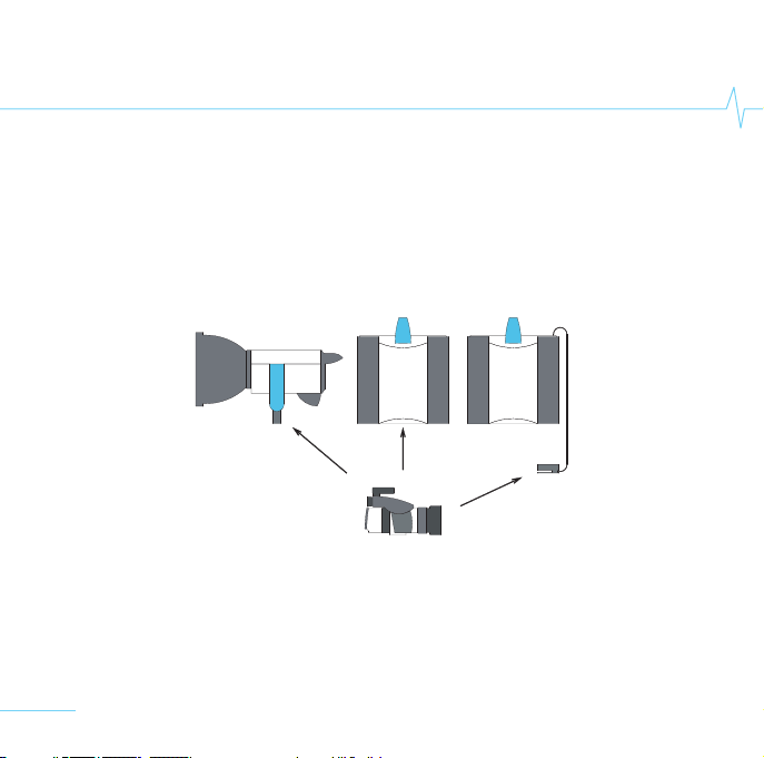
2. RADIO FREQUENCY SYSTEM 2.1 (RFS 2.1)
The radio frequency system broncolor RFS 2.1 consists of the following ele-
ments:
> RFS 2.1 as transmitter on the camera
> RFS 2.1 as receiver at the power packs / monolights without internal RFS 2 or
RFS 2.1 radio frequency system
> RFS 2 or RFS 2.1 as internal radio frequency system integrated in the power
packs/monolights
RFS 2
or
RFS 2
or
RFS 2.1
2.1 RFS 2 transceiver as transmitter
The RFS 2.1 transceiver is used to remote-control one or more broncolor
power packs or monolights equipped with RFS 2 or RFS 2.1 interface using
radio signals to trigger flashes. Power packs or monolights without integra-
ted RFS 2 or RFS 2.1 interfaces can be operated by connecting an RFS 2.1
transceiver (as receiver) to them (see chapter 1).
RFS 2.1
RFS 2 or RFS 2.1
RFS 2 or RFS 2.1
6
Page 6
To enable several RFS 2 or RFS 2.1 devices to communicate with each other,
they must all be set at the same studio address. RFS 2 and RFS 2.1 devices
with the same studio address can be simultaneously remote controlled. Thus,
thanks to the various studio addresses, several RFS 2 and RFS 2.1 groups of
units can be independently remote controlled without interfering with each
other.
Flash triggering is synchronized either via the central co ntact of the hot shoe
or the sync jack of the camera. Outdoors, the remote control range is up to
50 m; indoors, it is up to 30 m. The transceiver is powered by a lithium button
cell (Li-Mn CR2450). To minimise energy consumption, the transceiver is set
to an energy-saving mode after eight hours have elapsed. If a flash triggering
action occurs through the camera whilst the RFS 2 or RFS 2.1 transceiver is
in energy-saving mode, a slight delay of the synchronization with the camera
shutter release can take place. The RFS 2 or RFS 2.1 transceiver quits the
energy-saving mode after this flash release.
Attention: Although this radio system allows the selection of up to 99 stu-
dio addresses, the number of actually available channels depends on the
connected RFS 2 or RFS 2.1 flash unit.
For detailed instructions, please consult the manual of the respective flash
unit.
7
Page 7
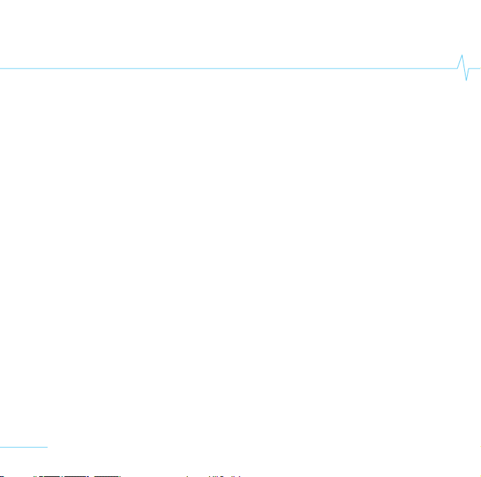
2.2 RFS 2.1 transceiver as receiver
The device can be used as an external receiver for broncolor power packs,
monolights, and third-party units that are not equipped to receive RFS 2 or
RFS 2.1 data. When using the device as a receiver, use the respective power
supply unit and plug it into the USB socket on the side of the device. The
device will automatically switch to the receiver mode.
Connect the sync cable with the "out" jack of the RFS 2.1 transceiver and the
sync jack on the flash unit.
2.3 Operation
>
Keys
The device has four keys: "test", "set", "" and "". Depending on the current
mode of the device, they have different functions. The functions depend on
how long the keys are pressed.
> Key press duration
A short key press is shorter than a second, a longer actuation is longer than
a second.
8
Page 8
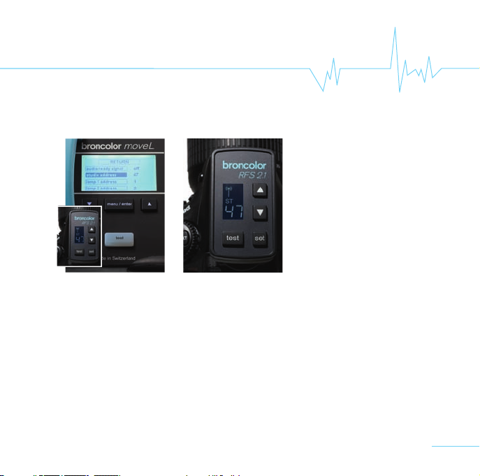
3. SET STUDIO ADDRESS
The transceiver must have the same studio address as the flash units or receivers that are to be used.
To set the studio address, please proceed as follows:
(the RFS 2.1 transceiver must be in "ST" mode. Should "LP" mode be selected,
change to mode "ST" by pressing "set" for longer)
1.) Press the "set" key briefly until the display blinks "ST" and shows the
studio number.
2.) Set the studio address with keys "
3.) Save the setting by pressing the "set" key briefly. The unit synchronises
with the flash units and "ST" is shown in the display (not blinking).
" and "".
9
Page 9
Overview of key assignment:
KeyOperation Function executed
test Press key brieflyTriggers a test flash
test Press key for longer Switches modelling light on or off
test + set
Press keys for longer than 4 s
Resets the unit
set Press key for longer Toggles between studio selection
and lamp selection
set Press key brieflyEnters menu
"Press key briefly
"
> adjusts power selection upwards
> adjusts studio channel upwards
> adjusts lamp channel upwards
""Press key briefly>adjusts power selection
downwards
> adjusts studio channel
downwards
> adjusts lamp channe
downwards
10
Page 10
Comments
(If the display does not illuminate, the unit must first be woken up by
pressing "set" briefly.)
If there is no action within 3 s, menu is exited again. (If the display does not
illuminate, the unit must first be woken up by pressing "set" briefly.)
Depending on status of unit
Depending on status of unit
11
Page 11
4. SETTING THE LAMP CHANNEL
With the RFS 2.1 Transceiver you can define and adjust the individual lamp
outlets on the flash units as you wish. To make the adjustments, please follow the procedure given in the operating instructions for the flash unit concerned.
To set the lamp address, proceed as follows:
(the RFS 2.1 Transceiver must be in "LP" mode. Should the "ST" mode be
selected, please change to mode "LP" by pressing "set" for longer)
1.) Press the "set" key briefly until the display blinks "LP" and shows the
lamp number.
2.) Use the "
3.) Save the setting by pressing the "set" key briefly.
" and "" keys to set the lamp address.
"LP" will now be displayed (without blinking).
12
Page 12
5.
ENERGY CONTROL
The RFS 2.1 transceiver allows you to change the power outlet of all RFS 2
or RFS 2.1 flash units that are set to the same studio address (in "ST" mode),
and to change the output of individual lamp channels (in "LP" mode). The
output can be adjusted in 1/10 and whole f-stops.
Mode "ST"
Briefly press the key "
all the RFS 2 or RFS 2.1 units increase the total energy by 1/10 f-stop
Briefly press the key "":
all the RFS 2 or RFS 2.1 units reduce the total energy by 1/10 f-stop
Long press of the key "":
all the RFS 2 or RFS 2.1 units increase the total energy by 1 f-stop
Long press of the key "":
all the RFS 2 or RFS 2.1 units reduce the total energy by 1 f-stop
":
13
Page 13
Mode "LP"
Briefly press the key "":
The lamp channel indicated increases its total output by 1/10 f-stop
Briefly press the key "
":
The lamp channel indicated reduces its total output by 1/10 f-stop
Long press of the key "":
The lamp channel indicated increases its total output by 1 f-stop
Long press of the key "":
The lamp channel indicated reduces its total output by 1 f-stop
> Resetting the device
To reset the device to factory settings, first press and hold the "test" key and
then press the "set" key for longer than four seconds. This resets the device.
14
Page 14
6. COMPATIBILITY
SystemCompatible with Comments
RFS 2.1 RFS 2.1
RFS 2
RFS 2RFS 2
RFS 2.1
RFSRFS No compatibility with RFS 2 or RFS 2.1.
On units with RFS 2, individual lamp and
modelling light settings are not possible
Only RFS 2 functions are available
(individual lamp and modelling light
settings are not possible)
Also no flash triggering.
15
Page 15
Transceiver technical data
Studio address setting range 1–99
Lamp address setting range 1–40
Radio frequency channels (automatically regulated) 40
Frequency 2.4 GHz
Transmission time (transmitter to receiver) 0.425 ms
Diaphragm shutter speed up to 1/1500 s
Focal-plane shutter speed up to 1/320 s
Flash triggering possible via:
> Integrated hot shoe on central contact
> Lateral 3.5-mm sync jack in or out
Range outdoorsup to 50 m
Range indoorsup to 30 m
Range up to 200 m
Integrated antenna
Dimensions (L x BxH) 68x38.5x33 mm/
Weight 46 g / 35 oz
16
2.7x1.5x1 inch
(including battery)
Page 16
Releases per second 100
Button cell battery in transceiver Li-Mn CR2450
(560 mAh, 3V)
Automatic switchover to energy-saving mode after 8 hours
Typical battery lifeapprox. 8–12 months
or 100,000 flashes
Sync voltage 3V
In the event of problems and undefined communication malfunctions between RFS 2.1 devices, the cause may be strong frequency interference.
In such cases, make sure the devices are not within the range of baby
phones, video bridges, microwave ovens, cordless dect telephones, Wlan
routers or Bluetooth devices, or use a different studio channel.
Subject to change in the interest of technical progress.
This device complies with Part 15 of the FCC Rules.
Operation is subject to the following two conditions:
(1) this device may not cause harmful interference, and
(2) this device must accept any interference received, including interference that may
cause undesired operation.
Changes or modifications not expressly approved by the party responsible for compliance
could void the user's authority to operate the equipment.
17
 Loading...