


Tessera Processor
User Manual
For M2, T1 and S4 processors
Software Version: V1.2

Contents
Contents 2
Chapter 1 - Introduction 10
Copyright 10
Trademarks 10
Changes 10
About This Manual 10
About the Tessera System 11
Handling and Safe Operation 11
Chapter2 - General Overview 12
General 12
System Overview 12
System setup diagram 13
M2 14
Front Panel 14
Front Panel Status LEDs 14
Rear Panel Connections 15
S4 17
Front Panel 17
Rear Panel 18
T1 19
Front Panel 19
Front Panel Status LEDs 19
Tessera Remote 19
Tessera Control 20
- 2 -

Chapter 3 - Quick Start Guide 21
Setting up your system 21
Setting up your project 22
Connecting your fixtures 23
Chapter 4 - Processor Settings 25
Processor Settings 25
Identification 25
Network Settings 26
Logging 26
Syslog 26
Enable Watchdog 26
Security 27
Date and Time 27
Fixture Firmware 28
Preferences 29
Auto Load 29
Status Bar 29
Canvas 30
Crash Management 30
Restore factory settings 30
Format internal storage 30
Reload firmware 31
Processor Status 32
About 32
Chapter 5 - Project Setup 34
- 3 -

Creating A New Project 34
Project Management 36
Opening and Importing Projects 36
Deleting Projects 37
Connecting Fixtures 37
Cabling 37
Connection Guidelines 38
Adding Fixtures to a Project 39
Adding Fixtures From Network 40
Sub-Devices 41
More About Topology and Associaton 43
Swapping Fixtures and Correcting Association 43
Changing Topology 44
Mapping Options 47
Interpolated Mapping 47
1:1 Mapping 47
Main Project Screen 48
Moving Around the Canvas 49
Fixture Layout 49
Selecting Individual Fixtures 49
Selecting Multiple Fixtures 49
Grouping Fixtures 50
Moving Fixtures 50
DeviceProperties 50
Beacon 51
- 4 -

Reset 51
Reload Firmware for Selected Panels 51
Test Pattern 52
Selected Calibration 52
Using the Grid 52
Snap to Fixtures 53
Rotating Fixtures 53
Canvas Modes 53
Edit Modes 53
Video On Canvas Modes 55
Layers 59
Chapter 6 - Input Properties 60
Sources 60
SDI Inputs 60
DVI Input 60
Source selection 60
Scaling and Cropping 61
Viewport 61
Active Area 62
Snap Active Area to Selection 64
4:3 and 16:9 64
Input Colour Control 65
Black Level 65
Contrast 65
Hue 65
- 5 -

Saturation 65
RGBShadow 66
RGBHighlight 66
Histograms 66
Setting Colour Controls with the Aid of Histograms 68
Crossfading 70
Test Patterns 70
Processor Test Patterns 70
Fixture Test Patterns 71
Beacon 71
Chapter 7 - Colour and Brightness 73
Intensity Gain 73
Brightness 73
RGB Gain 74
Colour Temperature 74
Gamma 74
Chapter 8 - Presets 76
Presets 76
Using Masking 77
Recording Presets 78
Editing Presets 78
Using Presets to Crossfade Between Inputs 79
Chapter 9 - Live Control 80
Introduction 80
Configuring the processor for DMX control 81
- 6 -

Configuring the processor for Art-Net control 82
Enabling Live Control 82
Parameter Indicators 84
Assign controls to a Group or Input 86
For Fixture Groups 86
For Input Control 87
Minimum and Maximum Values 88
Default Values 88
Chapter 10 - System Management 89
Network Load 89
Network Bit Depth 89
The Effect of Rotation and Interpolation on The Number of Supported Pixels 90
Fixture Interpolation 90
Importing Fixtures 91
Genlock Settings 92
Internal 92
Reference In 92
Locking to Video Inputs 92
Additional Video Delay 92
Custom Test Patterns 93
Low Latency Mode 93
Typical Latency 93
Typical Latency 93
Test Patterns 94
Processor Test Patterns 94
- 7 -

Fixture Test Patterns 95
Beacon 95
S4 Settings 96
Buttons 96
Chapter 11 - Remote Applications 98
Tessera Remote Application 98
Installation for Mac OS X 98
Installation for Windows PC 98
Network settings for Remote Management 100
To set the IP address on a Window PC 100
Setting the IP address in Mac OS X: 103
Connecting to a Tessera Processor 104
Tessera Remote Settings 105
Disconnecting from the processor 105
Offline Editor 105
Multiple Processor Control 106
Tessera Control 108
Chapter 12 - On-Screen Colour Adjustment 110
On-Screen Colour Adjustment (OSCA) 110
Display Colour 112
Display Video 112
Seam Adjustment 113
Seam Adjustment 113
Colour Adjustment 116
OSCAKeyboard Shortcuts 121
- 8 -

Appendices 123
Appendix 1: Keyboard Shortcuts 123
Appendix 2: Supported Resolutions 124
Warranty 127
WARRANTY CONDITIONS 127
Index 129
- 9 -

Chapter 1 - Introduction
Copyright
©2016 Brompton Technology Ltd. All rights reserved.
Trademarks
Brompton is a registered trademark owned by Carallon Ltd.
All other brand and product names used in this document may be trademarks, registered
trademarks, trade names of their respective holders.
Changes
The information and specifications contained within this document are subject to change
without notice. Brompton Technology Ltd reserves the right to make improvements and
changes to the hardware and software described in this document at any time and without
notice.
Brompton Technology Ltd assumes no responsibility or liability for any errors or inaccuracies
that might occur in this document.
About This Manual
This manual provides all the information required for the correct and safe use of the Tessera
processors and the supplied software.
This revision of the manual was written for the processor and remote software release:
V1.2
and was published on:
15 September 2016
- 10 -

About the Tessera System
The Tessera system comprises processors, receiving cards and software. These elements can
be used with a wide range of LED fixtures including panels, battens and mesh. Brompton
Technology welcomes all owners and manufacturers who wish to use Brompton processing
to control their LED video products.
For more information on becoming a Brompton partner please contact
info@bromptontech.com.
Handling and Safe Operation
The Tessera M2 processor is packaged in a rugged custom-designed 2U19" rackmounting
case with integral mounting handles.
Despite the strength of this case the processor should at all times be adequately supported
in a rack. The weight of the processor should never be supported entirely on the rack ears as
this can lead to distortion especially if the rack is roughly handled.
There are no user serviceable parts inside the unit and opening it will expose the user to
potentially dangerous voltages. The unit should never be operated with the cover exposed.
Opening the unit will invalidate the warranty.
The product is designed to operate from a grounded power source between 100 and 250V
AC, 47 -63Hz . Care should be taken to make sure this is a stable power source and if surges
are possible a wise precaution may be to place the unit on an uninterruptible power supply
(UPS).
- 11 -

Chapter2 - General Overview
General
Brompton Technology make three Tessera LEDvideo processors for different applications:
M2, T1 and S4.
The M2 is the flagship in the Tessera range of processors. It can control up to 2 million pixels
over four Gigabit outputs and can accept incoming signals in a wide variety of formats up to
and including 3G-SDI and up to 1080p60.
The T1 has the front-side processing, scaling, rotation and DMXcontrol of the M2 processor
but with a single Gigabit output and can control up to 0.5 million pixels.
Meanwhile, the S4 processor does not have the front-side processing, scaling, rotation of
the T1 and the M2, but can control the same number of pixels across four Gigabit outputs as
the M2.
System Overview
The M2 processor can receive video input signals on any one of up to 3 ports:
l SDI A
l SDI B
l DVI-I/ Analog
The T1 and S4 processors only support DVI-D.
These inputs are dealt with in more detail in "Chapter 6 - Input Properties" on page60.
The Tessera processors can be controlled either via a mouse and keyboard or via a Mac or PC
running the Tessera Remote software and connected via Gigabit Ethernet. The processor
has an integral DisplayPort output port for local control and monitoring, and connects to
fixtures via four Gigabit Ethernet outputs (supplied on etherCON™ connectors). Each Gigabit
output can be distributed via standard Gigabit Ethernet peripherals such as switches and
fibre optic transceivers.
- 12 -

System setup diagram
Figure 2-1. Typical system set-up
- 13 -

M2
Front Panel
A Front Panel Status LEDs
2 x USB2.0 type Aports, which allow for the connection of USBmemory storage
B
devices, peripherals such as keyboard or mouse or other USBdevices
Front Panel Status LEDs
LEDName Indication
Active Is lit whilst Local User Interface or Tessera Remote in use
Ethernet
DMX In A DMX signal is being received by the processor
Video In The processor is connected to a valid video input source.
Reference In
Tessera Out The processor is connected to panels.
Black/Freeze Either the blackout or freeze button has been enabled.
Overtemp
When blinking indicates that the processor is detecting a
network connection.
The processor has a valid source of genlock connected to
the reference input connector.
Off: temperature normal
Blinking: processor overheating but operational
On: processor overheated and shutdown
- 14 -

Rear Panel Connections
M2 processor
M2B processor
Remote Control
A
Connect a PC or Mac running the Tessera Remote or Tessera Control application, or
an eDMX protocol directly to the local data Gigabit Ethernet port.
Local User Interface
The M2 Processor can be operated locally with a monitor connected via DisplayPort.
B
Peripherals such as mouse and keyboard can be connected to the USB ports on either
the front or rear panel.
DVI Input
A DVI input of up to 1920x1080 @ 60Hz (148.5MHz pixel clock) is available. This is a
C
DVI-I input which supports DVI-D, VGA/ RGBHV and Component Analog (YPbPr)with a
suitable adapter.
- 15 -

Reference Input
D
Used for analog bi-level or tri-level sync.
DMX 512-A Input
E
For DMX real-time control.
3G-SDI Input
Two 3G-SDIinputs are available. Both inputs can be used concurrently. The SDI inputs
F
support up to 3G-SDI level A or level B. Both inputs can be used together to support
Dual Link HD-SDI.
Loop Thru Ports
G
All video inputs and syncs have re-clocked loop thru ports.
DisplayPort Input
H
Not currently implemented.
Gigabit Ethernet Outputs
The M2 processor has four Ethernet outputs which are provided on EtherCON
I
connectors. Fixtures should be connected with gigabit Ethernet cable (Cat-5e or
above). For more information on Ethernet connection see "Connecting Fixtures" on
page37.
On/Off Switch
The processor can be turned off from the power switch. It can be shutdown from the
J
local interface or remote computer. No harm will result from turning the processor
off at the switch.
IEC Mains Input
K
The input is auto ranging from 100-250v/47-63Hz
DMX512-AInput and Thru
L
For DMXreal-time control
Remote Control Ports
The M2Bhas two Gigabit Ethernet ports for Remote Control. These act like a switch
M
and can be used for daisy-chaining in to other Tessera processors.
- 16 -

S4
Front Panel
A Front panel status LEDs
B Black Button:sends the output of the processor to black
C Freeze button:freezes the output of the processor
2 x USB 2.0 type Aports, for the connection of USBmemory storage devices, peri-
D
pherals such as a keyboard or mouse or other USBperipherals
Front Panel Status LEDs
LEDName Indication
Active
Ethernet
Video In The processor is connected to a valid video input source.
Tessera Out The processor is connected to panels.
Overtemp
Blinks whilst Local User Interface or Tessera Remote application in use
Processor is connected to Tessera Remote. When blinking
indicates that the processor is detecting a network connection.
Off:Temperature normal
Blinking: processor overheating but operational
On: processor overheated but shutdown
- 17 -

Rear Panel
Gigabit Ethernet Outputs
The S4 processor has four Ethernet outputs which are provided on EtherCON
A
connectors. Fixtures should be connected with gigabit Ethernet cable (Cat-5e or
above). For more information on Ethernet connection see Connecting Fixtures on
page 1.
DVI-D Input
B
A DVI-D input of up to 1920x1080 is available, with a reclocked DVI-D thru
Local User Interface
The M2 Processor can be operated locally with a monitor connected via DisplayPort.
C
Peripherals such as mouse and keyboard can be connected to the USB ports on either
the front or rear panel
Remote Control Ports
D
The S4has a Gigabit Ethernet port for remote control with Tessera Remote software
only.
IECMains Input and On/Off Switch
The S4 processor supports a voltage range of 100V-240V, and a mains frequency
E
range of 50 - 60Hz. The processor can be turned off from the power switch. It can be
shutdown from the local interface or remote computer. No harm will result from
turning the processor off at the switch.
- 18 -

T1
Front Panel
A Front panel status LEDs
2 x USB2.0 type Aports, for the connection of USBmemory storage devices, peri-
B
pherals such as a keyboard board or a mouse or other USBperipherals
Front Panel Status LEDs
LEDName Indication
Active Blinks whilst Local User Interface or Remote Control in use
Processor is connected to Tessera Remote. When blinking
Ethernet
DMX In A DMX source is connected to the processor.
Video In The processor is connected to a valid video input source.
Tessera Out The processor is connected to panels.
Black/Freeze Either the blackout or freeze button has been enabled.
Overtemp
indicates that the processor is detecting a network connection.
Off: temperature normal
Blinking: processor overheating but operational
On: processor overheated and shutdown
Tessera Remote
You can access the processor’s user interface remotely using a Mac or Windows PC
connected directly to or on the same network as the processor by installing and running the
Tessera Remote application. You may also use this application's Offline Editor mode to
design your configuration without being connected to a network. The project can then be
- 19 -

imported to the processor via USBflash drive and connected to fixtures on the network at a
later date.
For details on how to install and use Tessera Remote, see "Chapter 11 - Remote Applications"
on page98
Tessera Control
Tessera Control is an application available for Mac and Windows PCsthat allows live control
of multiple processors on the same network from one application. See "Chapter 11 - Remote
Applications" on page98
- 20 -

Chapter 3 - Quick Start Guide
To get a basic system up and running, just follow these steps. This guide covers starting a
new project with fixtures connected. To set up a project offline and connect fixtures at a
later stage, see "Chapter 11 - Remote Applications" on page98. Further information on all
the features contained in this Quick Start Guide can be found in the relevant sections of the
manual.
Setting up your system
Figure 3-1. The Rear Panel
1. Connect your fixtures to the Ethernet output ports, using Gigabit Ethernet cable (Cat
5e or above) and network switches, if necessary, using Ethernet connection rules.
2. Connect your video input source(s) to the DVI and/or SDI input ports.
3. Connect a monitor to the Local UI DisplayPort connector. If you are using DVI, HDMIor
VGAwith the monitor then you will need to use the relevant DisplayPort adaptor. Connect a keyboard and mouse to the USB ports. Alternatively, you can access the processor's user interface through a Mac or Windows PC running the Tessera Remote
application.
4. Connect the IEC mains input and switch the processor on. When the processor has
powered up, the monitor will display the Start Screen. The processor may be configured to auto-load a previous project, which it will do after a set amount of time, by
default 10s, if the user does not invervene. If a previous project auto-loads it is necessary to close the project to return to the Start Screen.
- 21 -

Figure 3-2. The Start Screen
Setting up your project
5. From the Start Screen, select New… The New Project Wizard will launch.
Figure 3-3. The New Project Wizard
6. Type in a name for your project. If you are using Tessera Remote in offline mode, you
can also select the location in which it is to be saved (if you are accessing the processor
directly, the project will be saved to its internal storage).
7. Select the fixture type from the dropdown menu and uncheck the Create an array of
panels box. If you are using more than one fixture type, click the Go To Advanced View
button. Select the fixtures required. You can hold CTRL whilst selecting to select mul-
- 22 -

tiple fixtures.
8. Click Create. You will now be taken to the Main Project Screen.
Figure 3-4. Main Project Screen
Connecting your fixtures
Figure 3-5. Add fixture from network button
Click the Add Fixtures From Network button. The Add Fixtures From Network toolbar will be
displayed.
- 23 -

Figure 3-6. The Add Fixtures From Network toolbar.
1. The processor will show any attached strings of fixtures and the number of fixtures on
each string. In the picture above, the processor can see fixtures connected to outputs
1, 2 and 3. Outputs 1 and 2 have a single string of 9 fixtures on each output, whilst Output 3 has 4 strings with 12, 18, 24, and 12 fixtures.
2. Click on the string of fixtures you wish to add. The first fixture in the string will be highlighted white, while the other fixtures will display varying shades of the same colour to
denote the the order of the fixtures in the string from dimmest to brightest.
3. Click on the canvas to add the first fixture in the string, then add subsequent fixtures
in the string using the same method.
4. Repeat the process for all strings, then click the green Back arrow to return to the
Main Project Screen. The connected fixtures will start to output video and the fixtures
on the canvas will display a green circle to indicate they are online.
Figure 3-7. A highlighted Recoloured string
- 24 -

Chapter 4 - Processor Settings
From the Main Project Screen it is possible to set a number of user definable settings for the
processor. In the Main Project Screen choose Settings from the Tools menu.
Figure 4-1. Tools dropdown menu
Processor Settings
Figure 4-2. Processor Settings
Identification
It is possible to change the name of the processor as it appears when you connect to it
remotely. This can be particularly useful when building a system that uses multiple
- 25 -

processors. If no name is set the processor will be displayed by its serial number in the
Discovered Processors list in Tessera Remote.
Network Settings
The default IP address of a Tessera processors is 192.168.0.50 with subnet mask of
255.255.255.0.
In addition to being able to set the processor to different static addresses and ranges it is
also possible to set processors to receive an IPaddress from a DHCP server.
The gateway field allows you to add the IPaddress of a network gateway such as a router.
When using more than one processor on the same network it is recommended to use the
processors on different IPaddresses within the same IPrange.
Logging
The processor can log its actions in a file which can be viewed from the Tools menu in the
Main Project Screen. This information can be useful when trying to track what was
happening directly before a fault or crash.
It is possible to set the level of detail logged by the processor in this menu ranging from
Critical (lowest) to Debug (highest). A high level of detail may reveal more of what the
processor was doing at a given moment, however it may make it more difficult to find the
salient information.
Syslog
This feature is not implemented yet.
Enable Watchdog
The watchdog is an hardware level process separate from the main processor which
monitors the processor and restarts it if it stops responding, even in the event of a complete
processor crash . With the watchdog disabled the processor will remain in this state until it is
manually rebooted. This may be desirable sometimes when you are trying find the reason for
an issue, but generally it is preferable to have the watchdog enabled. This is the default
setting.
- 26 -
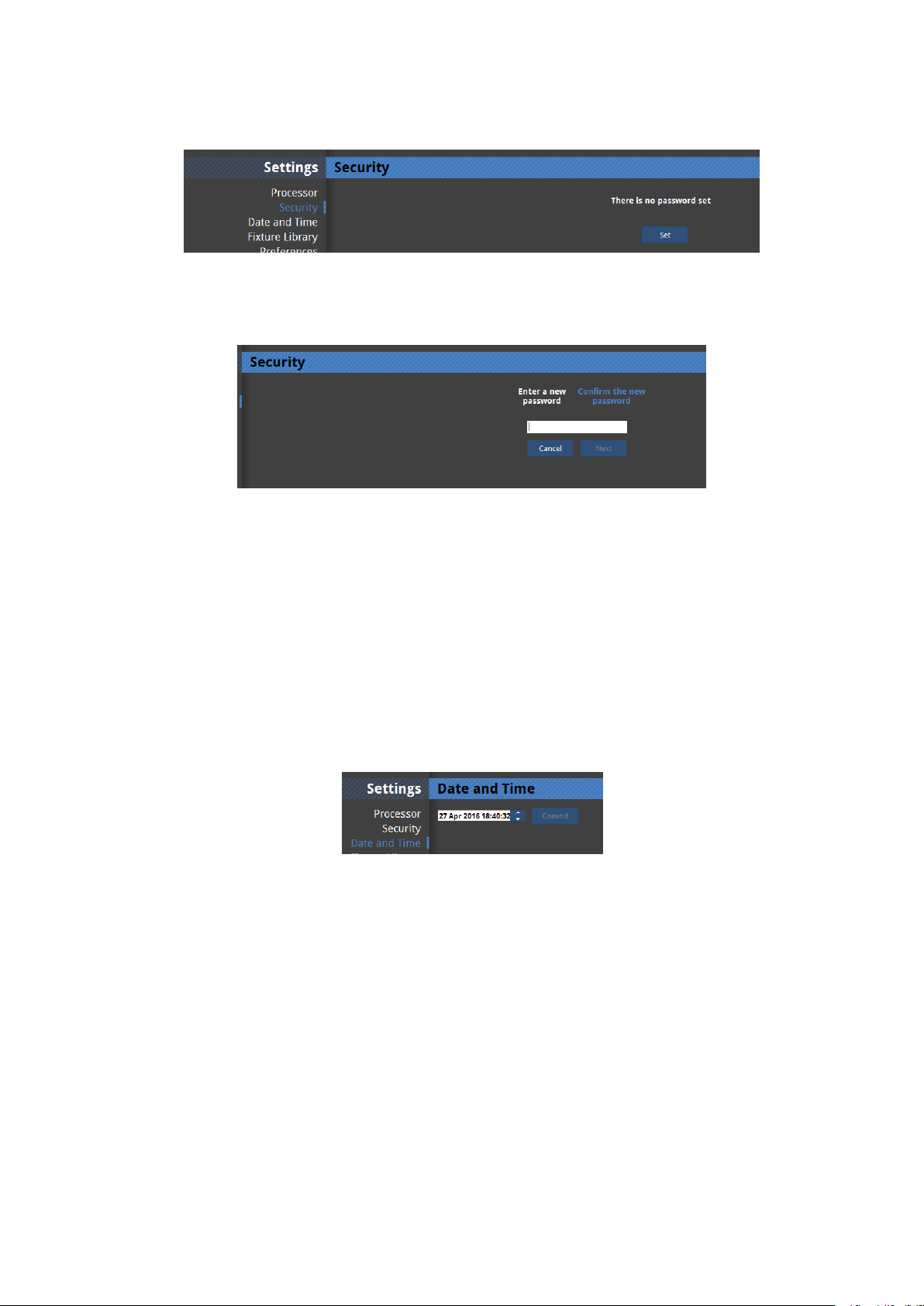
Security
Figure 4-3. Security settings with no password set- the default setting.
Figure 4-4. Setting a password
It is possible to set a password for the processor. This password will then be requested from
users connecting to the processor from the Tessera Remote application. The password is
reset if factory settings are restored or it can be removed by re-entering the password in this
window.
Date and Time
Figure 4-5.
It is possible to set the date and time of the processor. To do this click separately on the day,
month and year of the processor so that it becomes highlighted. You may then type in a new
value or use the up and down arrows to change the values. This information is used in log
files and crash reports.
- 27 -

Fixture Firmware
Figure 4-6. Fixture Firmware screen
This window allows you see which version of fixture firmware is currently set as the preferred
for each type of supported fixture. Typically this will be the firmware version included with
that version of processor software.
Should you wish to set the processor to upload a different version of fixture firmware which
was not included with the release software of the processor it is possible to load newer (and
older) versions of fixture firmware and assign these as the default for a particular fixture.
To do this:
1. Click on the Import... button at the top of the screen. You can now load new firmware
from a USB flash drive or from the hard drive of a connected PC if using Tessera
Remote.
2. Once the firmware is loaded assign that file to be the default by selecting the type from
the list and selecting the firmware version from the dropdown menu at the bottom of
the screen.
- 28 -

Note. This window does not load firmware to any fixtures. It simply sets the preferred file to be
used if you do decide to reload firmware from this processor. For more information on fixture
firmware and the options for reloading see Reload Fixture Firmware
Preferences
Figure 4-7. Preferences
Auto Load
When the processor is turned on you are taken to the Start Screen, which displays Recent
Projects on the right. The last used project file will appear at the top of this list and, if within
10 seconds no other file is selected or no other option is chosen, the processor will
automatically load this file. If you do not want the processor to do this it is possible to disable
this option so that the processor remains on the Start Screen until an option is selected.
Note. It is possible to change the autoload countdown time to a value between 0-3600 seconds.
It may be desirable to set this value to zero before the processor is used on a show, as this will
mean that in the event of a power cut the processor will reboot straight into the current
project file with the minimum of delay.
Status Bar
Figure 4-8. The Status Bar
The status bar is the line of text information in the bottom left corner of the Main Project
Screen. This appears when the cursor is hovered over certain icons or when particular
- 29 -
operations are undertaken. It provides keyboard shortcut information and tips to aid the
user. If you wish to turn this offyou can uncheck this option.
Canvas
This section contains settings to help with selecting and aligning fixtures on the canvas.
These features are explained in "Using the Grid" on page52 and "Fixture Layout" on
page49.
Crash Management
It is possible to set the processor to report crashes. If this option is enabled the processor
will pause after a crash before rebooting to allow time for the user to enter information
about what actions were performed before the crash. The time duration of this pause can be
set between 0 and 3600 seconds. The saved crash reports can then be exported to a USB
flash drive or similar. The crash reporter is to set to on by default.
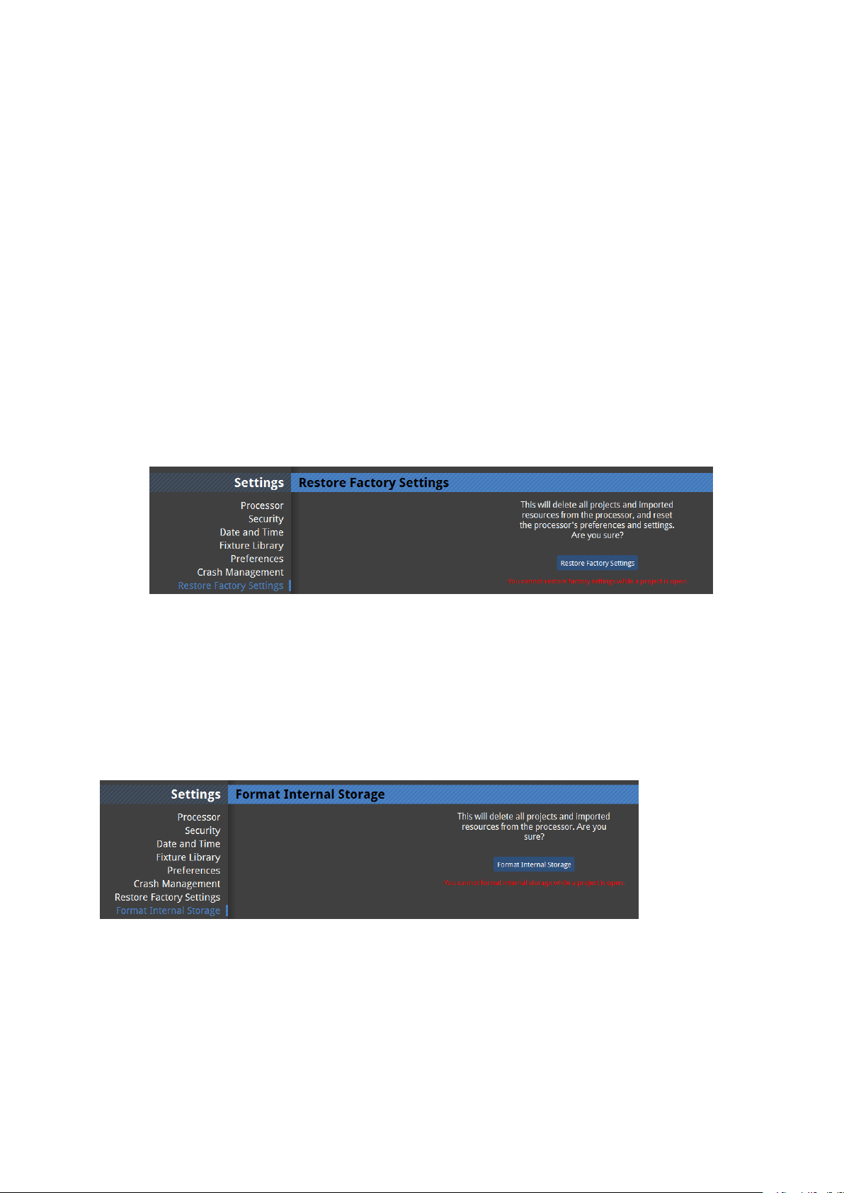
Restore factory settings
Figure 4-9. Restore factory settings
Restoring the factory settings will set all user definable characteristics of the processor back
to defaults. This will wipe all project files from the memory of the processor and also any
imported fixture definition files and fixture firmware not included in the current software
release.
Format internal storage
Figure 4-10. Format internal storage
- 30 -

Format internal storage will overwrite the memory of the processor. This will wipe all project
files from the memory of the processor and also any imported fixture definition files and
fixture firmware not included in the current software release. The current software version
of the processor will be retained after an internal storage format has been performed.
Reload firmware
Figure 4-11. Reload Firmware
The reload firmware option allows the user to change the software which runs the
processor. Any firmware builds which are uploaded to the processor are stored in internal
flash memory and so you may see some older or newer builds under the heading Choose
from existing.
If you do not see the build you wish to use in this menu you can load it from a USB flash drive
or from the hard drive of a remote computer running Tessera Remote. To do this click on
Browse and navigate to the location where the firmware is stored. You can download the
latest processor software from our web site: www.bromptontech.com/support.
Once you have uploaded or chosen the build you wish to use you can reload the firmware.
This is a very quick process after which your project files and additional fixture definition files
should still be available to you. However it is wise to have backup copies of important project
files before a firmware upgrade as a precaution.
Note Newer firmware versions will almost always allow you to load project files started on
older versions of firmware. Projects started on newer versions of firmware will not normally
work on older versions of firmware.
- 31 -

Processor Status
Figure 4-12. Processor status window
The processor status window gives a significant amount of useful information on the current
setup and the condition of the processor. This ranges from details of the current software
and hardware setup to data about the temperature, network settings and revision numbers
of particular components in the processor.
It is possible to export this data to an external USB flash drive or similar by clicking on the
export button at the top of the page. You will then be able to choose the location to save
the file which will have the name “xxxx_state.xml”, where xxxx is the processor serial
number. This can be very useful if you need to contact support and is one of the things which
may be requested.
About
The About window contains info regarding the end user license agreement between
Brompton and the user. Also included are third party license agreements relevant to the
- 32 -

software, the company address and the support email address:
support@bromptontech.com
- 33 -

Chapter 5 - Project Setup
Creating A New Project
Figure 5-1. The New Project Window
The New Project Wizard is launched each time you start a new project on the processor,
Tessera Remote or the Offline Editor.
1. To start a new project, click New… in the Start Screen or in the Project menu in the
Main Project Screen. This will launch the New Project Wizard.
2. Using the wizard, enter a name for your project.
3. If you are using the Offline Editor in Tessera Remote, you can change the location of
where the project is saved. If you are using the processor locally or remotely, the project will be saved to the processor’s internal storage. To save the project on to a
- 34 -

USBflash drive or an other USBstorage deviceyou will need to export it. See "Project
Management" on the next page
If you are creating a project with only one fixture type:
1. Select the manufacturer and fixture type from the dropdown menus.
2. Specifythe width and height of the array of fixtures to be generated automatically.
Alternatively, you may uncheck the Create an array of fixtures tickbox and add fixtures manually once the project is created.
3. Select the topology from the dropdown menu or leave this at the default setting if you
want to add the topology manually once the project has been created.
4. Click Create to complete the new project wizard and open the new project.
If you are creating a project with more than one fixture type:
1. Click Go to Advanced View and select the fixture types you require from the list using
CTRL+ click. If the required fixture type is not listed, you may import it by clicking
Import Types… (more information on importing fixture types can be found in " Importing Fixtures" on page91).
2. For 1:1 pixel mapping, check the Map pixels directly to the canvas (1:1) tickbox. See
"Mapping Options" on page47
3. The M2 supports a 1920x1080 raster by default, but can also be set to 1080 x 1920,
1600x1200, 2880 x 720 and 720 x 2880 by selecting this from the drop-down menu in
Canvas Size. Using these alternative resolutions puts the processor in to Low Latency
Mode. See "Low Latency Mode" on page93 for the implications of using this mode
- 35 -

Figure 5-2. Selecting a canvas size from the Advanced View
2. In the advanced mode, you do not have the option of automatically generating an
array of fixtures - the fixture types you have selected will be available in the library once
the project has been created. Click Create to complete the wizard and open the new
project.
Note: Once a project file has been created it is not possible to include additional fixture types
or change the method of pixel mapping. Making changes to the included fixture types and pixel
mapping will require the creation of a new project file.
Project Management
Opening and Importing Projects
To open a project that is stored on the processor, you simply click Open... from the Start
Screen menu or File drop-down menu in the Main Project Screen and select the project from
the list. If the project you wish to open is not already stored on the processor you will have to
import it.
Figure 5-3. Importing projects in the project management window.
To import a project if you are using the processor with a locally connected keyboard, mouse
and monitor:
- 36 -

1. Insert the USB flash drive containing the project file into one of the available USBports
on the processor.
2. Click Open... on the Start Screen or in the File drop-down menu in the Main Project
Screen. This will display the Project Management window.
3. When you have selected the file, click OK. This will copy the project file on to the processor and display it in the list of projects stored on the processor.
4. Select the file from this list and click OK to open it.
To import a project if you are connected to the processor via Tessera Remote:
1. Click Import Project... in the project management window and navigate to the project
file you wish to load, either stored on the remote computer's hard drive or inserted
removable media.
2. When you have selected the file, click OK. This will add the project file to the list of projects stored on the processor.
3. Select the file from this file and click OK to open it.
Deleting Projects
1. Click Open... on the Start Screen or from File drop-down menu in the Main Project
Screen. This will display the Project Management window.
2. Select the project or projects (hold Ctrl to select multiple files).
3. Click Delete Projects. The selected files will immediately be removed from the processor.
Connecting Fixtures
Cabling
The Brompton Tessera M2 processor can drive any Tessera compatible LED panel, mesh or
batten system. Most panel products will have a panel controller card fitted inside each
cabinet or tile. In the case of ray or batten type products where there is a low pixel count per
fixture, the panel controller card may be housed in a buffer box and a number of fixtures
connected to each buffer.
All Tessera compatible LEDfixtures have two Gigabit Ethernet ports: one to allow
connection from the processor and one to connect to the next unit in the chain. These ports
can be used interchangeably.
- 37 -

The processor communicates with LED fixtures on the network using the Tessera protocol,
which is transmitted via cabling that conforms to Cat 5e or above (this includes Neutrik
etherCON terminations).
The topology of a Tessera system is very simple. The fixtures just need to be connected to
the processor either directly or via a Gigabit Ethernet network switch. Once connected, a
group of fixtures in an daisy-chain becomes a string.
Note: The Tessera Protocol only supports Gigabit Ethernet compliant equipment. It will not
work at all with 100BaseT(Fast Ethernet)or 10BaseT
Connection Guidelines
Cat 5e or better cable must be used to connect between processors and fixtures. The
maximum supported individual cable length is 100m. The Tessera protocol can be
transmitted over standard Gigabit Ethernet compliant fibre optic hardware for single runs
exceeding this distance.
The suggested maximum number of nodes between the processor and the furthest panel in
any system is 5 switches and 50 panels (fibre optic transceivers would also count as
switches). By using switches up to 500 fixtures can be run from a single processor output
port (assuming this does not exceed the pixel limit of the output).
Each output port from the processor can control up to a maximum of 525,000 pixels at 60Hz
at a network bit depth of 8 bit. "Network Load" on page89 for a precise explanation of how
the pixel limit per output is affected by different layouts and network bit depths.
Note: The Tessera Protocol does not support connection over WiFi
- 38 -

Adding Fixtures to a Project
The diagram below shows a typical system setup with some strings connected directly from
the processor and some via a network switch. Each differently coloured group of panels
represents one of the strings in the screenshot in the previous section. The red and green
strings are connected directly to output ports 1 and 2 of the processor. The light blue,
yellow, dark blue and purple strings are connected to port 3 via a network switch.
Figure 5-4. An example of a Tessera system topology.
The topology (cabling) of a Tessera system is very simple. The fixtures just need to be
connected to the processor either directly or via a switch. Once connected, a group of
fixtures in an unbroken line becomes a string. Each string is represented by a different colour
in the user interface and can be placed on the canvas as desired.
There are two ways to add fixtures to your project . If you already have fixtures connected,
you can add these directly to your canvas. Alternatively, you can add offline fixtures to your
canvas, that are then associated with fixtures on the network at a later stage (see Section Associating Fixtures).
- 39 -

Adding Fixtures From Network
Once the fixtures are physically connected to the network, the processor will auto-detect
them (provided the fixture types were selected when the project was created) and the Add
Fixtures From Network toolbar ("Add Fixtures From Network toolbar. " below) will turn
green. If fixtures are connected but not appearing see"Troubleshooting" on page 1 .
Figure 5-5. Add Fixtures From Network button.
Clicking on the button will switch to the 'Add Fixture from Network toolbar in the Main
Project Screen.
The picture below shows how a typical system with multiple strings might appear once
fixtures are connected and have been auto-detected . The blue numbers indicate the output
port and the numbers in the coloured boxes denote the number of fixtures in each string
(see "Add Fixtures From Network toolbar. " below).
Figure 5-6. Add Fixtures From Network toolbar.
As new strings are added they can be given a colour by clicking the Highlight Strings button.
The actual fixtures will then display the colour shown in the Add Fixtures from Network
toolbar and can then be quickly and easily added to the canvas in their correct position by
first clicking on the coloured square then on the canvas.
- 40 -

Sub-Devices
Sub-devices are fixtures that have a smaller pixel count than traditional LEDpanels, and
often have a different shape or format, such as LEDstrips. Sub-devices are connected to
special controller boxes called Root Nodes which supply power and data to the Sub-devices
and are sometimes referred to as PDUor Power and Data Units. These Root Nodes contain a
Tessera Receiver Card and are connected to one the processor's Tessera Protocol outputs,
just as you would connect a conventional LEDfixtures.
Figure 5-7. Sub-devices being used with conventional LEDpanels.
Sub-devices can be laid out and positioned like conventional fixtures; however, they must be
associated and configured with the relevant Root Node. Root Nodes can be configured in
the Online Panels window.
- 41 -

Figure 5-8. A Root Node with unassociated Sub-devices
To configure connected Root Nodes: select the relevant Root Node you wish to configure so
that it is highlighted. Note that Sub-devices can be shown or hidden by selecting the Show
Sub-devices button.
Click on the Configure button to open the Configure Root Node dialog box.
If the root node has more than one output port these will be shown as separate boxes.
Figure 5-9. The Configure Root Node dialog
Ports on the selected Root Node can be selected and then Sub-devices can be selected from
the drop down menu and assigned by clicking on the Add Devices button.
- 42 -

It is worth noting the system will limit the number of sub-devices according the maximum
supported capacity of the Root Node.
Please see the manufacturers documentation for further details on configuring specific Subdevices.
Figure 5-10. Associated Sub-devices
More About Topology and Associaton
The Tessera system uses the unique MAC address of each fixture to identify the order of the
fixtures. When the fixtures are associated the system assigns MAC addresses of real world
connected fixtures to the relevant fixture icons on the canvas. The order of the fixtures in
sequence is also set at this timeand it is this order which defines the topology.
The system will recognise the order of the MAC addresses of connected fixtures. This can be
particularly useful where the topology of a string has been designed offline. In these
instances it is only necessary to associate the first fixture in a string by clicking on it using the
discovered fixtures tools and the whole string will then automatically associate.
Swapping Fixtures and Correcting Association
Each fixture connected to an M2 is recognized as a unique fixture. Each unique fixture is
associated with a position on the canvas. If a tile goes offline or is removed the icon of that
fixture remains in the canvas but there is now no fixture associated with it. The green dot
(showing that the panel is online) will now go white. In instances where a fixture is swapped
out from the middle of a string the processor can see that a fixture has disappeared and a
new fixture has appeared in the same position. It draws the conclusion that a swap-out has
taken place and will offer the user the option to correct association.
To perform the swap-out of one fixture:
- 43 -
1. Disconnect and remove the faulty fixture or controller box.
2. Insert and connect a good fixture into the same position in the string.The processor
will prompt with:
Figure 5-11. The correct association dialog box
3. This message will be on screen for 10 seconds. After this time you can find the Correct
Association option by right clicking on the icon of the affected fixture or by selecting
Correct Association from the Edit menu.
4. Click on the blue Correct Association button.
Changing Topology
It is possible to change the topology manually using the Topology toolbar if the drawn
topology does not match the actual sequence of fixtures. An example of where this might be
useful is a touring production where a screen has been rebuilt at the second venue of the
tour with a different cable layout to that used at the first venue. These instructions assume
the panels are powered and connected and the mistake has just been noticed.
In our example, at the first venue the panels were cabled in a continuous lace from left to
right and from bottom to top as viewed from the front of the screen ("First venue
topology." below).
Figure 5-12. First venue topology.
Owing to a mistake during the load in at the second venue the panels are now cabled
differently ("Second venue topology." on the next page). It will be too time-consuming to recable the screen correctly so another solution must be found
- 44 -

Figure 5-13. Second venue topology.
To correct a screen follow the following steps:
1. On the canvas select all the panels that have the wrong topology. Right click on one of
the panels and select Disassociate.
2. Now click the Edit Topology button to view the Topology toolbar
and select the string of fixtures you wish to correct by double clicking on the dot in the
centre of one of the panels. The whole string will now be coloured red.
Figure 5-14. The topology is drawn on all panels in the string.
3. The strike in the Remove Link button will change from grey to red once a string is selected indicating that it can now be used.
Click on it to remove the topology.
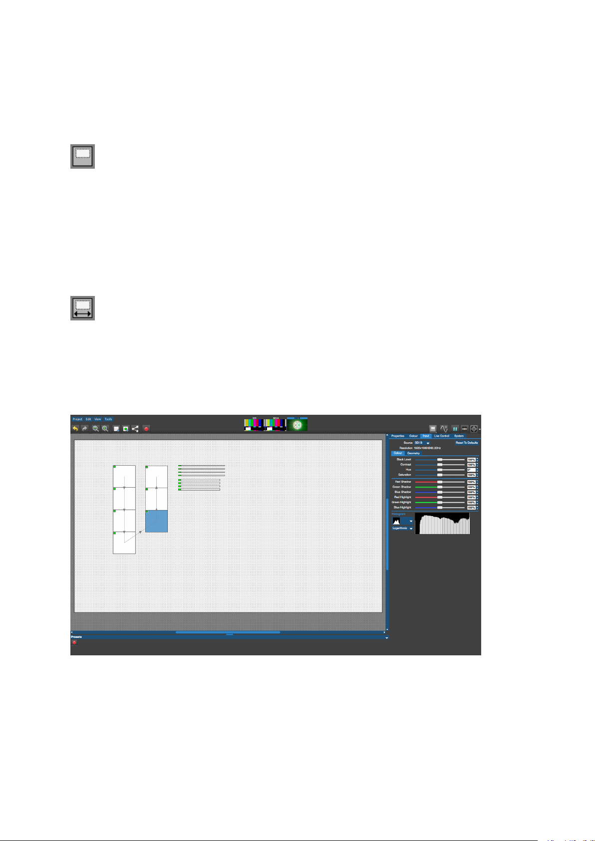
4. Now hover your mouse over the centre spot of the fixture which is to be at the start of
the string. Click and hold the button and drag the pointer to the centre spot of the
- 45 -

second panel on the string. A dotted red line will be drawn which will go solid as the
line becomes pinned to the centre spot of the next panel in the string. You can now
move on to the third fixture in the string and so forth until the string is complete.
Figure 5-15. Changing the topology by clicking and dragging the mouse pointer
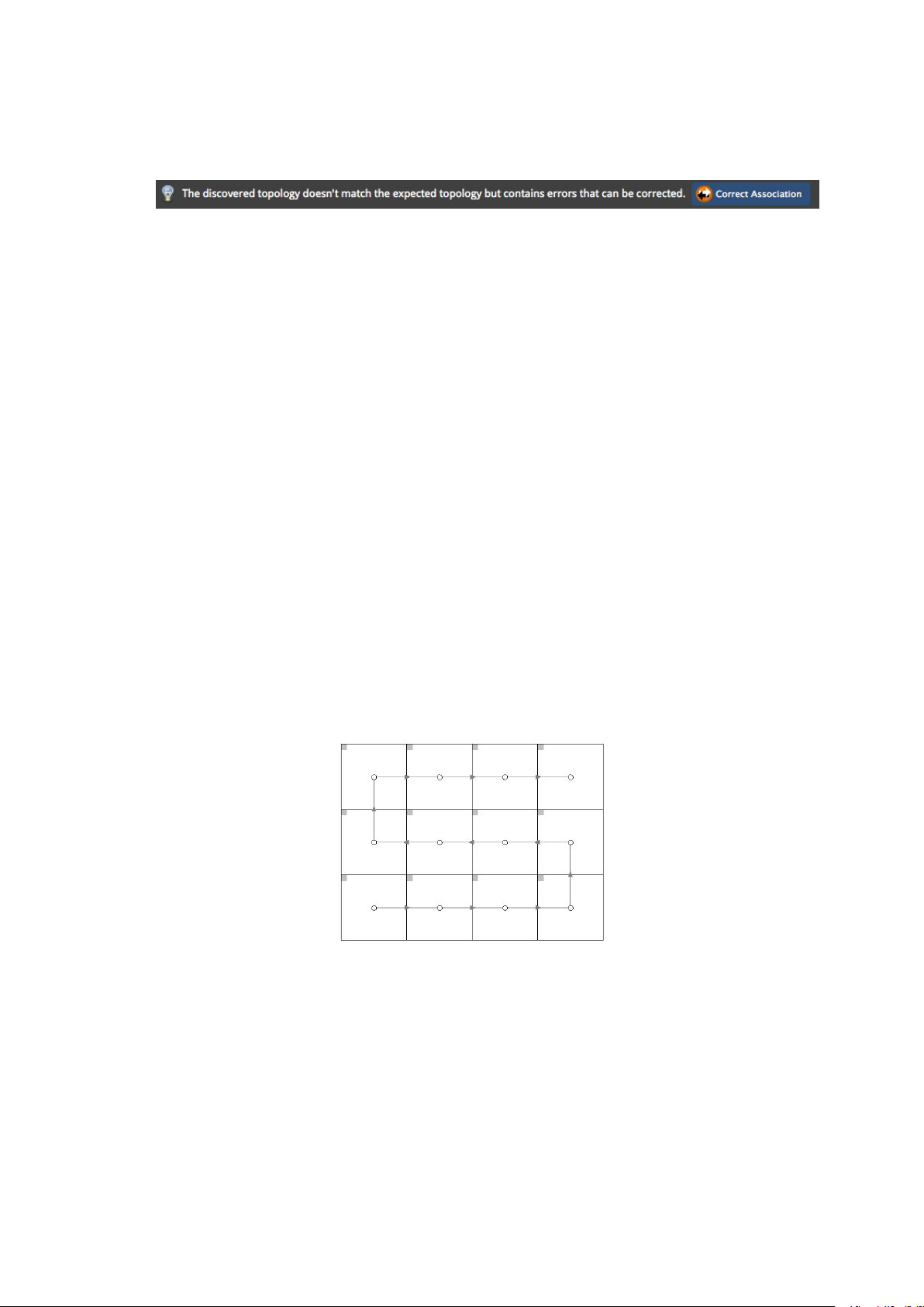
5. Return to the main project toolbar by clicking on the green arrow. The processor will
recognise that there is a new topology which doesn’t match the current association
and will display the Correct Association message for 10 seconds.
Figure 5-16. The Correct Association message
6. Click the Correct Association button to finish the process. The fixture icons will display
the green dot in the canvas window and content can be displayed on the fixtures "The
panels are online and associated." below).
Figure 5-17. The panels are online and associated.
After this timeyou can correct association by right clicking on the icon of the affected fixture
or by selecting Correct Association from the Edit menu.
- 46 -

Alternatively you can display the Add Fixtures from Network toolbar to see the unassociated
fixtures icon highlighted with a colour. Click on this icon and then click on the first fixture in
the string to associate the fixtures. Now click on the green arrow to come out of the Add
Fixtures from Network toolbar and the fixtures will associate and come online.
Mapping Options
Interpolated Mapping
When multiple fixtures are added, the processor will by default automatically adjust the
scaling for each fixture type so that video appears the same physical size on all fixtures,
regardless of pixel pitch.
It's worth remembering in this mode when different pixel pitches are scaled to match each
other it may not be possible to place as many fixtures in the Canvas as would have been the
case without interpolated mapping. If this is an issue it may be desirable to use 1:1 mapping.
Please see the section on Network Load in Chapter 9 for the implications on network load of
Interpolated Mapping.
1:1 Mapping
In some cases where multiple fixtures are used it may be desirable ignore the physical size of
each fixture and instead map video content directly to the LED fixtures. In this mode it is the
resolution (i.e the number of LEDs)that determines the size of the fixture on the canvas, not
the physical dimensions. This may be because content has already been prepared with the
correct scale for each product or to allow more fixtures to be placed in the canvas.
To do this check the box marked “Map pixels directly to the canvas (1:1)” in the advanced
view of the New Project Wizard (see "Creating A New Project" on page34).
- 47 -

Main Project Screen
Figure 5-18. Main Project Screen
1. Drop-down menus
2. Left Toolbar:
l Undo and Redo
l Zoom In and Out
l Add Fixtures
l Add Fixtures from Network
l Change Topology
l Record Preset
3. Source Previews
4. Processor Name/ Processor serial number
5. Right Toolbar:
l Canvas Mode
l Live Control On/Off
l Pause/Freeze
l Blackout
l Test Patterns
6. Property Tabs
7. Presets
8. The Canvas
- 48 -

Moving Around the Canvas
Up and down
vertical scrollbar
arrow keys
page up/down keys
mouse wheel
Left and right horizontal scrollbar
arrow keys
shift + mouse wheel
Zoom in and out
mouse wheel +Ctrl
Drag the canvas
Hold the space bar and left click + drag the
mouse
Fixture Layout
Selecting Individual Fixtures
To select a fixture simply click on it. The fixture will turn blue and information such as
manufacturer, type and position is displayed on the Properties tab. You can also right-click
on a fixture to display a context menu.
Selecting Multiple Fixtures
There are various methods of selecting multiple fixtures:
l Hold down the Ctrl key and click fixtures to select them.
l Alternatively, hold down the left mouse button and drag a selection box around the
fixtures to select them (see Selection Mode info box below).
l To select all fixtures on the canvas, you can use CTRL + A.
Selection Mode In Settings > Preferences you can change the selection mode from Inside
- 49 -

selection area to Overlaps selection area. If 'Inside selection area' is enabled, the line must
completely enclose fixtures in order to select them. If 'overlaps selection area' is enabled, a
fixture will be selected if any part of it falls within the selection area.
Grouping Fixtures
If there are several fixtures in your configuration that you always want to move and adjust
together, it may be helpful to put them into a group. To do this select the required fixtures,
right-click and choose Group from the dropdown menu. You can also Ungroup in a similar
manner.
Moving Fixtures
You can move fixtures anywhere on the Canvas, either within or outside of the Active Area,
by selecting the fixture and dragging or pressing the arrow keys on the keyboard. Pressing
the arrow keys will move the fixture by grid-space increments if the grid is displayed and snap
to grid is enabled or, if not, by pixels.
Device Properties
DeviceProperties displays the selected fixture's device properties in the Properties Tab.
These include the fixture's MAC address, serial number and firmware version.
Figure 5-19. Device Propertie
- 50 -

Beacon
The Beacon button highlights selected fixtures by using the Identify test pattern which
features a white border with a dark blue on each of the selected fixtures. The status LEDs will
also flash on the back of the selected fixtures.
Figure 5-20. ABeaconed panel showing the Identify internal test pattern.
Reset
Reset allows the selected fixtures to be reset
Reload Firmware for Selected Panels
This allows firmware to be uploaded for selected fixtures.
- 51 -

Test Pattern
The Test Pattern drop-down menu allows you to select a range of internal test patterns that
are generated on the fixtures themselves. These patterns are particularly useful for testing a
range of fixture and fixture module based issues.
Figure 5-21. Internal Test Pattern drop-down menu.
Selected Calibration
The Selected Calibration drop-down menu allows the selection of different colour calibration
profiles that might be stored in a fixture. The amount of different colour calibrations
available is dependent on how much flash memory available for calibrations on the fixture.
Figure 5-22. Selecting between the internal calibration and uncalibrated.
Using the Grid
The grid is a useful tool to help align or space fixtures evenly on the canvas. Enabling Snap to
Grid will pull fixtures into perfect alignment at all times.
- 52 -

The grid can be displayed by right-clicking on the canvas in the Main Project Screen and
toggling Show Grid in the context menu. Snap to Grid can be enabled in the same way.
These options can also be accessed in Tools > Settings > Preferences. Selecting Properties
from this right-click menu, displays grid colour and spacing options in the Properties tab on
the right-hand side of the screen when the canvas itself is selected.
Snap to Fixtures
When laying out fixtures on the canvas it is often helpful to be able to place them exactly
adjacent to one another without spaces between them. When Snap to Fixtures is enabled a
fixture will be pulled towards other fixtures it is dragged near. This option can be accessed in
Tools > Settings > Preferences or by right-clicking on the canvas and toggling Snap to
Fixtures in the context menu.
Rotating Fixtures
Fixtures and groups of fixtures can be rotated by selecting them and entering the degree of
rotation in the Properties tab. Individual panels rotate around their top left corner. Groups
rotate around their anchor point, indicated by a small circle that is placed by default in the
centre but can be moved using the Rotation Center settings in the Properties tab.
NB The S4 processor can only rotate in 90 degree increments.
For further information on how rotating fixtures affects network load see "Network Load"
on page89.
Canvas Modes
Canvas modes can be selected by clicking on the clicking on the Canvas mode icon on the
toolbar and selecting the relevant mode from the drop-down menu or by using the assigned
keyboard shortcut.
Edit Modes
The edit modes allow fixtures to be positioned on the canvas.
- 53 -
Edit Mode:
(keyboard shortcut F1)
Edit Mode is the default mode for the canvas and allows fixture positioning. In Edit mode the
fixtures are displayed as viewed from the front.
Rear Edit Mode:
(keyboard shortcut F2)
Fixtures are commonly cabled up from behind and Rear Edit allows fixtures on the canvas to
be horizontally flipped, as if viewed from behind. This is particularly helpful for figuring out
and fault-finding topologies.
Figure 5-23. Edit Mode
- 54 -

Figure 5-24. Rear Edit Mode
Video On Canvas Modes
Video on Canvas modes allows the display of the currently selected video input, taking into
account Viewport and Active Area settings. Video on Canvas Modes are not available on
Tessera Remote. Fixtures cannot be moved on the canvas whilst in Video on Canvas Modes.
Fixture Only Mode:
(keyboard shortcut F3)
Fixture only mode displays the currently selected video input as it is being displayed on the
fixtures.
- 55 -

Figure 5-25. Fixture Only Mode
Video and Fixture Mode:
(keyboard shortcut F4)
Video and Fixture Mode displays the currently selected video input on both the fixtures and
the canvas. The video within the Active Area that is not being displayed on the fixtures is
shown greyed out as shown in the picture below.
- 56 -

Figure 5-26. Video and Fixture Mode
Video Only Mode:
(keyboard shortcut F5)
Video Mode displays the currently selected video input within the Active Area on the canvas
without displaying the fixtures.
- 57 -

Figure 5-27. Video Mode
Figure 5-28. Video Mode with scaled input
- 58 -

Layers
Figure 5-29. The Layers tab
Layers are an easy way of manipulating overlapping fixtures.
Fixtures can be assigned to layers which have a z-order. Z-order refers to the front to back
ordering. Assigning panels to layers that make tasks such as On Screen Calibration (OSCA)
and other fixture based adjustments easier. Layers are particularly useful when two groups
of panels are superimposed on the canvas, so that the content can be easily duplicated on
two sets of fixtures, much as in a Imag screen application, with two screens showing the
same content on either side of the stage. Layers make it easier and more accurate to select
between the two groups of panels to make OSCAor other panel based adjustments.
The tick allows you to show or hide layers without effecting the output. Clicking and
dragging a highlighted layer up or down allows the z-order of the layer to be adjusted.
Layers should be assigned when associating fixtures. See "Connecting Fixtures" on page37.
To do this you should be in the Add Fixtures from Network window. Select the relevant layer
you wish to add fixtures to. You can create a new layer by using the Add Layer button in the
Layer Tab.
With the relevant layer highlighted, add the required fixtures from network. To add fixtures
to a new layer, select the layer and add the fixtures to that layer.
A total of 16 layers can be created.
- 59 -

Chapter 6 - Input Properties
Sources
SDI Inputs
The M2 processor has two SDIinputs.
The SDI A and SDI B inputs are identical in functionality. Each input provides SD-SDI, HD-SDI
and 3G-SDI(both level A and level B). Alternatively, both inputs may be used together for
dual-link HDSDI. All common broadcast resolutions are supported, including 720p50/60,
1080i50/60 and 1080p50/60 and fractional frame rates such as 59.94. For a full list
"Appendix 2: Supported Resolutions" on page124.
The physical connections to the SDI A and B inputs are via standard BNC connectors and in
addition to each input there is a re-clocked thru connector which allows the daisy chaining of
a signal to a second processor or monitor.
There is also an active SDI Out for each channel which is for future implementation.
DVI Input
The M2 processor is fitted with a DVI-Iinput, but the T1 and S4 processors have a DVI-D input.
All Tessera procesors are capable of receiving digital (DVI-D) signals up to full HD 1080p60
resolution at frame rates from 24Hz to 60Hz to a maximum pixel clock of 148.5MHz.
The M2 processor is also capable of receiving analogue VGA/RGBHV inputs up to full HD
(though for this you will need a suitable adaptor for the DVI-I input port).
The DVI-I input may also be used to receive standard definition or high definition component
video (YPbPr) via a passive DVI to BNC breakout cable. In addition to the DVI-I input there is
also a re-clocked DVI-I output.
HDMI can be supported by use of a suitable adapter, however, the Tessera processors does
not support HDCP.
Source selection
The three video inputs on the Tessera M2 processor are mapped to two input pipelines to
allow crossfading between sources.
- 60 -

Although it is possible to crossfade from input to another ("Crossfading " on page70), it is
not possible to display multiple inputs simultaneously, either as picture-in-picture or as
discrete windows.
The incoming video on each of the three inputs can be quickly viewed in the Main Project
Screen where you will see the three Input Thumbnails ("Source preview thumbnails."
below).
Figure 6-1. Source preview thumbnails.
The currently selected input will have its legend highlighted in blue. The quickest way to
change inputs is to double click on the input you wish to switch to. Alternatively, you can
click on the Input tab to see the Source drop down menu and select the different inputs from
here.
Any of the inputs may be used as a reference signal for genlock (See section "Genlock
Settings" on page92).
Scaling and Cropping
The Tessera M2 processor achieves scaling and cropping of the incoming feed by use of three
settings in the input tab: Viewport, Zoom and Active Area.
Viewport
The Viewport settings define the region of interest of the incoming feed which is captured to
the canvas. Typically this will be captured in full, so an incoming HD feed would have settings
of:
- 61 -

Figure 6-2. Incoming 1920x1080 video at its original size.
If however you wish to capture only part of that incoming feed (perhaps because you then
wish to expand the image to fill the canvas) you can set these values accordingly.
For example, if you wished to capture a window of PAL content being displayed towards the
bottom right corner of an HD feed you might set the Viewport to:
Figure 6-3. Viewport set to bottom right corner
In addition to the left, top, width and height parameters there is also a Snap to Input button.
This automatically sets the width and height to match the full size of the incoming video
feed.
Active Area
On the canvas, the Active Area is indicated by the pale grey area with a dashed border ("The
canvas with the Active Area shown by a dashed border." on the next page). Settings are
found on the Geometry section of the Input tab.
- 62 -

Figure 6-4. The Geometry Tab
Figure 6-5. The canvas with the Active Area shown by a dashed border.
Having determined the region of interest to be captured from the incoming feed using the
Viewport, that region can then be sized or moved to the appropriate part of the canvas.
To set the Active Area to the same dimensions as the Viewport click the Snap to Viewport
button. Content will be shown with no scaling but with cropping according to the Viewport
Settings. As with the Viewport setting, the Active Area will default to the same parameters
as the incoming video feed.
To scale the content, you can set the Active Area dimensions to values greater or smaller
than the Viewport. You can change the size of the Active Area by dragging the dashed line
on the canvas or entering values in the Width and Height fields. The active area may not be
greater than what the maximum canvas size has been set to.
To change position use hand cursor or adjust the top left coordinates manually.
- 63 -

Snap Active Area to Selection
To automatically size the incoming image to fit on a particular group of fixtures, select the
chosen fixtures and click the Snap to Selection button
The Active Area will then be sized and positioned to fit over the selected fixtures.
4:3 and 16:9
The 4:3 and 16:9 buttons will automatically adjust the width parameter of the Active Area to
the chosen ratio based on the height. For example, if the Active Area dimensions are width
200 x height 90, clicking the 16:9 button would reduce the width to 160 and the height
would remain 90.
Zoom
The Viewport is scaled and mapped onto the Active Area according to the Zoom mode. The
zoom options are:
1:1 The original Viewport image size.
Fit
The aspect ratio of the Viewport is maintained with the
image scaled to fit within the active area.
- 64 -

Fill
The aspect ratio of the Viewport is maintained with the
image scaled to fill the active area.
Stretch
The image is scaled to the exact dimensions of the active
area without maintaining aspect ratio.
Input Colour Control
Black Level
The black level control affects the base level of brightness of the darkest content in the
incoming feed. Lowering this value will make all parts of the image look darker (except for
white)but will be most pronounced at the lower end of the video signal nearest black. For
optimum adjustment of the black level a PLUGE or greyscale line-up pattern can be useful.
What is PLUGE? Picture line-up generation equipment (PLUGE or pluge) is equipment used to
generate greyscale test patterns in order to adjust the black level and contrast of a picture
monitor. Images generated from these tools can be saved and stored as bitmaps and these
images are sometimes referred to as PLUGE themselves.
Contrast
Just as the black level control sets the threshold of the base level of dark content, the
contrast slider sets the threshold level of bright content. Boosting this level will increase the
differential in luminance between the darkest content and the brightest content.
Hue
The hue parameter of the input controls allows the user to adjust the spectrum of the
incoming video feed. At the extreme this will reverse the colours assigned to each area of a
given hue.
Saturation
The saturation parameter determines the level of colour in the image and can be used to
increase or reduce this. At the extremes this would make the image monochrome with only
- 65 -

brightness information intact or boost its colour to give a more colourful (perhaps too
colourful) image.
RGBShadow
In addition to being able to set a black level for a given input it is also possible to set the
black level specifically for each of the primary colours in that input. These sliders, called RGB
Shadow, equate to a setting for the black level of each specific colour.
RGBHighlight
In addition to being able to set contrast for a given input it is possible to set a contrast (white
level) for each of the primary colours also. These parameters are called RGB Highlight.
Histograms
A useful tool offered by the Tessera processor is a selection of histograms. Histograms
depict distribution of pixels across the possible range of a colour or colours of the incoming
video feed in real time after they have been modified by the input colour controls. There are
six different histograms available:
l Luminance
l Red
l Green
l Blue
l Red, green and blue and luminance with separate histograms
l Red, green and blue luminosity with overlaid histograms
All histograms can be displayed linearly or logarithmically.
Their main use is to allow the user to identify and compensate for perceived deficiencies in
the incoming video feed. The user can then see how changes to the input colour controls
may be affecting the colour content of that feed. By adjusting those controls it may be
possible to boost the amount of colour depth of the displayed signal, resulting in a better
distribution of peaks in the histogram.
The X-Axis of each histogram is graded from 0% to 100% and shows a column to indicate how
much content there is at that percentage of the given colour. The Y-Axis showing the
amount of content at a particular percentage is auto-ranging in scale and adapts to fill the
axis.
The logarithmic scale will accentuate small columns so tiny areas of a particular colour can
be visualized in instances where one particular percentage dwarfs all others.
- 66 -
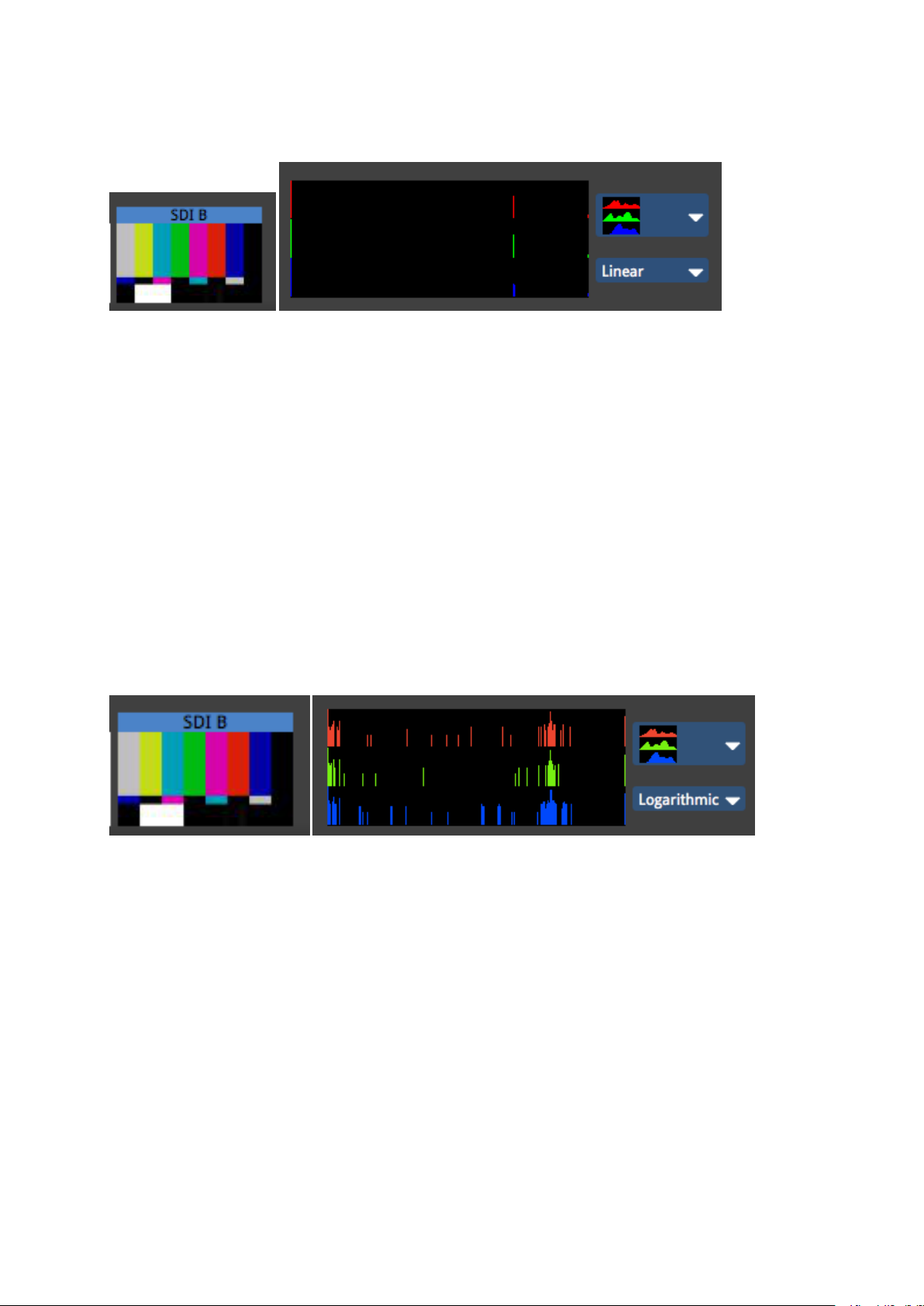
Figure 6-6. Test pattern showing colour bars at 75% and the corresponding Linear RGB
histogram.
The above picture shows a test pattern and its corresponding Linear RGB histogram. Note
that there are clear columns at 75% for each of the three primaries. This is because all of the
colours are either primary colours at 75% (red, green and blue sections) or secondary colours
made from combinations of the primaries at 75% (cyan, yellow, magenta and white sections).
There is also a large peak at 0% on the left which shows how much black there is in the image
(quite a lot) and also a clear peak on the right which shows an area of 100% RGB and is
caused by the single block of 100% white towards the bottom left of the image (you can see
this white is noticeably brighter than the grey-looking vertical section white is made by
mixing 75% red, green and blue).
Figure 6-7. Test pattern showing colour bars at 75% and the corresponding Logarithmic RGB
histogram.
The above picture shows a logarithmic visualization of the input. Although the same three
areas 0%, 75% and 100% show the highest concentrations of columns there are now more
areas visible. So we can see that there are some small amounts of colour which deviate from
these three values and the image is not quite as perfectly composed of 75% colour as might
have been assumed from the linear scale.
- 67 -

The fact that the peaks corresponding to the black and white areas of the input image are
located at the very start and end of each histogram indicates that this content source is well
balanced and the full spectrum is being used.
Setting Colour Controls with the Aid of Histograms
The histograms can be useful in determining if a particular incoming signal is filling the entire
spectrum of colour and brightness.
When choosing an image to balance, it is wise to either use an image which is similar to the
content you plan to show throughout your project, an image with a wide variety of colours and
hues, or a suitable test pattern.
Figure 6-8. A fairly washed out incoming signal on SDI-B (see thumbnail top left) with the
corresponding histogram for red, green and blue when the Input Colour Controls are set to
default.
Figure 6-9. Adjusting the black level control will make the blacks look darker and the
concentrations of colour now reach down to 0% on the scale.
- 68 -

Figure 6-10. Adjusting the contrast control will make brighter areas appear closer to the 100%
threshold, assuming you have some areas of white content in your image and this is desirable.
If specific colours do not appear to be rendering correctly you may wish to adjust the RGB
Highlight and Shadow controls to work on that specific colour without affecting the other
two primaries. At this point it may be helpful to look at the histogram for each colour
individually.
- 69 -

Crossfading
Crossfading between inputs is achieved by storing the different inputs as presets with a
crossfade time. To store presets to crossfade from one input to another follow these steps:
1. Select the input you wish to create a preset for (all tiles will change to this input).
2. Click the preset record button. If the tiles of the group are selected they will appear
red. If they appear with diagonal striped lines select them again.
3. Now hit the Preset button on which you want the new preset to reside. Right-click the
preset to rename it.
4. Click on the input thumbnail of another input to change to that input.
5. Repeat steps 1-4 to create a new preset for this input.
6. Now right-click on each preset in turn to see its properties and to set a fade timefor
the preset.
You are now ready to use the presets you have created to crossfade between the inputs.
*As inputs are global to all tiles it will not matter if all the tiles in the system are in this group
or not. Selecting the resulting preset will always change the input for the entire system.
What happens when you change inputs on the M2? The M2 processor has two input pipelines
each of which can process up to a 1920x1080p raster at 60Hz. When an input is selected, that
input gets mapped to the currently unused pipeline and this is then fed into the mixer and
scaler functions of the processor further down the line. Once any crossfading is complete the
other pipeline is then free for the next selected input, as and when that is chosen.
Test Patterns
Processor Test Patterns
The Tessera processor has a selection of built-in test patterns. These can be used to verify
the correct performance of the fixtures and also to verify that a finished layout of fixtures are
in the correct arrangement.
To activate test patterns click on the test pattern button in the right hand corner of the
main project window.
Figure 6-11. Test Pattern button with associated drop-down menu that allows the selection of
the relevant test pattern
- 70 -

To turn off test patterns click on the icon again and it will turn grey.
To change test pattern click on the small white triangle to the right of the icon and it will
give a selection of test patterns as shown in figure X.
Custom Test Patterns allows custom test pattern bitmaps to be loaded into the processor.
Fixture Test Patterns
In addition to the processor test patterns it is possible to trigger test patterns on individual
fixtures or groups of fixtures by selecting them in the canvas. The test pattern can then be
triggered from the Properties tab.
On some fixtures it is also possible to trigger these test patterns using a self test button on
the back of the tile (refer to fixture manufacturer documentation for specific functionality).
Beacon
The beacon tool allows the user to highlight a particular fixture in the system from the
canvas window. This can be particularly useful when trying to identifypanel products with a
fault
- 71 -

The beacon button can be found towards the bottom of the Properties tab. It will highlight
the panel in solid blue with a white border around the edge. If the panel is equipped with
status LEDs these will flash yellow allowing easy recognition from the rear also.
- 72 -

Chapter 7 - Colour and Brightness
There are four ways to modifythe colour and brightness of fixtures connected to the Tessera
system.
l Global colour - the controls on the Colour tab will affect all fixtures connected to the
processor. Global Colour controls are located on the Colour tab to the right of the
Main Project Screen.
l Per-panel colour - it is possible to override the Global Colour settings for specificfix-
tures by enabling the Override Global Colour option on the Properties tab, which activates a set of sliders contained there (see Override Global Colour later in this chapter).
l Per-Group specific colour - colour settings can be adjusted for individual Groups of pan-
els by enabling the Override Global Colour option as above.
l Input colour - you can modifythe colour balance of a specific input (DVI, SDI or ana-
logue).
Intensity Gain
The Intensity Gain slider in the Global Colour settings allows users to modifythe light output
of all the fixtures in the system in a perceptually linear way, so at 50% fixtures will look half as
bright to the naked eye as they did at 100%. The precise light output of the screen will depend
on this value in conjunction with the Brightness slider.
Brightness
The brightness scale allows adjustment of the light output of the screen. As all fixture types
are calibrated when the profile is written, the brightness scale is expressed in Nits
(candela/m2). This means arrays with different fixtures can quickly be set to the same output
level.
Where more than one type of fixture with different maximum brightness values is used, the
slider will cease to have an effect on a fixture's brightness once its maximum value is
exceeded.
The brightness slider will have a default value of the brightest value that all the fixtures in a
project can reach. Therefore if a project consists of two different types of fixtures, one of
which has a maximum output of 5000 Nits and one of which has a maximum brightness of
2000 Nits the default value of the brightness slider will be 2000 Nits. Similarly the maximum
- 73 -

value of the slider will be the value of the brightest fixture in the project, so in this example it
would be 5000 Nits.
Tip: If you wish to control the brightness of an array including different types of fixtures whilst
maintaining them at a matching level then this is best achieved by leaving the brightness slider
at default and modifying the intensity slider.
RGB Gain
The RGB gain controls allow the user to adjust the level of each of the primary colours in the
output to the connected fixtures. Their default value is 100%.
Adjusting all 3 RGB sliders to 50% would have the same effect on perceived brightness as
lowering the Intensity slider to 50%.
Colour Temperature
The Temperature slider allows the user to adjust the white balance of the fixtures attached
in a range from 2,000-11,000 Kelvin.
Gamma
Gamma can be modified in a range from 0.2 up to 4.0. The default gamma setting of the M2 is
2.35.
Gamma or gamma correction is a way to adjust how bright the midtones in the image appear
without affecting the very dark or very bright areas of the image. A higher value results in
lower brightness. If images are not gamma encoded, they allocate too many bits or too much
bandwidth to highlights that humans cannot differentiate, and too few bits/bandwidth to
shadow values that humans are sensitive to and would require more bits/bandwidth to
maintain the same visual quality. By increasing the differential between areas of shadow and
light in certain parts of the luminance curve of a particular piece of content it is possible to
increase the amount of detail that can be perceived by the eye, thus rendering the image in
more detail and with more contrast. This gamma correction is done by a simple function. In
most computers images are encoded with a gamma constant equivalent to about 0.45 and so
are decoded with a gamma of approximately 2.2. Mac computers used to be encoded at 0.55
and hence decoded at 1.8. This is why it often helped to set a lower gamma value on the
output of a display when it was connected to a MAC computer source for best results. Since the
Mac OSX Snow Leopard release Apple have changed their default gamma values to a value
more in line with the 0.45/2.2 ratio used by other manufacturers Override Global Colour
- 74 -

Figure 7-1. Global Colour Override
It is possible to remove single fixtures or groups of fixtures from the control of the Global
Colour sliders and assign values to them separately. This functionality may be useful if you
wish to maintain one whole screen at a constant brightness when there are fixtures grouped
into separate screens on a processor.
Alternatively you may have individual fixtures whose native colour values have drifted. Using
the override controls it may be possible to match their colour more closely to the rest of the
system.
The option to Override Global Colour is found on the Properties tab. To do this first select
the fixture or group you wish to override. If you wish to override a number of fixtures
simultaneously with the same values then first select them and make them into a group.
If the selection is a single panel you have the option to adjust Intensity, Red, Green and Blue
gain sliders for the selection.
If the selection is a group there is also the option to control Brightness, (Colour)
Temperature and Gamma.
Note Once a selection has been overridden on the Properties tab the global colour controls
will have no effect on it until the Override Global Colour box is unchecked.
- 75 -

Chapter 8 - Presets
Presets
Presets are a way of storing the settings that you make on the processor so that they can be
recalled quickly and easily. These presets can be made to affect all the panels or a small
selection of them depending on how they are grouped. This information may be brightness,
colour input or perhaps positional information. Video and Colour Presets affect all groups,
Position presets affect the particular Group of fixtures they were recorded for.
The preset buttons can be seen at the bottom of the Main Project Screen.
Figure 8-1. Main Project Screen with record buttons highlighted.
Presets are a powerful tool for recalling parameters and fixture positions. For example, if a
screen is in place for an outdoor festival it may be useful to set different colour and
brightness settings during the day to compensate for changes from day to night-time or
cloudy versus sunny conditions. Storing these changes as presets means they can be
recalled quickly the next day when conditions change again.
Types of information can include:
l Positional information - the placement of Groups of fixtures on the canvas.
l Colour information - the colour parameters in the colour tab (global colour) and also
the per panel and per group colour values in the Properties tab.
- 76 -
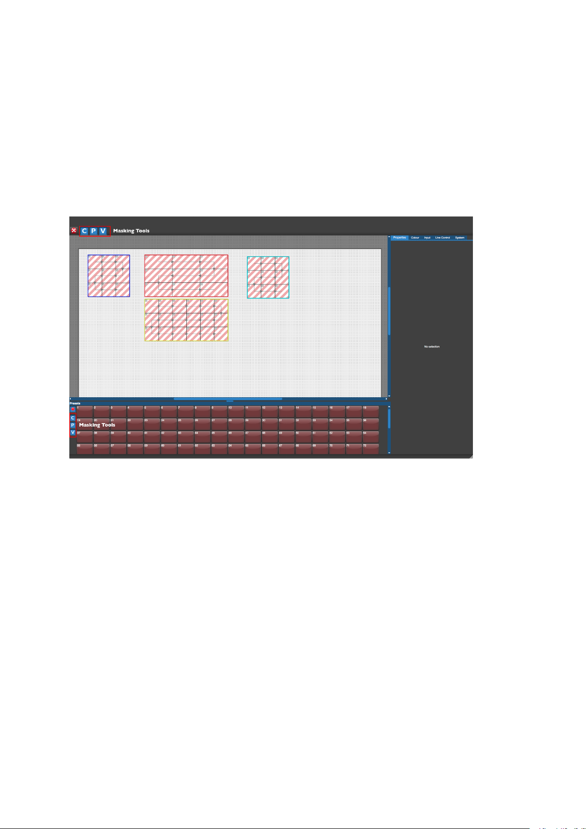
l Video information - the parameters contained in the inputs tab including the selected
input source, the colour and brightness information for each input and the geometry
information (Viewport and Active Area).
Pressing one of the Record Preset buttons opens the Preset Recording view.
Using Masking
Figure 8-2. Preset Recording view
Sometimes it may be desirable to load positional information without changing the colour
information of a group of panels or perhaps change the input source without affecting the
global colour. This can be achieved by using masking.
When you store a preset the three letter icons C, P and V that appear after pressing the
Record button are all lit in blue (default). This indicates that, in this preset state, information
will be stored for all the values of colour, position and video that are currently set for those
panels. If you click on any one of these icons at this point it will be deselected and turn grey.
So it is then possible to store just the colour, position or video settings or a combination of
the three.
- 77 -

Recording Presets
Before storing a Position preset it is necessary to combine the panels you want to be
controlled into a group (see "Fixture Layout" on page49).
Note: A group can consist of a single panel.
To record a preset:
1. Set the parameters of colour, position or video that you wish to store as a preset and
select or deselect the masking controls: C, P and V.
2. Click the red preset record button. The tiles of the available groups will appear with
striped diagonal lines.
3. Click on the group or groups you wish to select for the preset. Once the group or
groups are selected the diagonal lines will change to solid colour. Only the group or
groups which are selected will be stored into a Position preset.
4. Click the preset button on which you want the new preset to be stored. The preset can
now be recalled whenever needed by clicking on the preset recall button.
Editing Presets
To change any parameters of a stored preset, recall the preset by clicking on the preset
recall button, make the alterations and re-record it.
- 78 -

Right-click on a preset recall button to rename or delete it.
Using Presets to Crossfade Between Inputs
Switching inputs can be achieved by creating a Video (V) preset for each input. This is a
feature only available on M-Series processors.
To assign crossfade times to these presets right click on each preset and select properties.
The properties of each preset will now appear in the properties tab and there is an option
here to assign a crossfade time.
Note. The cross fade time does not apply to Colour and Position parameters or any of the other
Video parameters except input selection.
- 79 -

Chapter 9 - Live Control
Introduction
Live Control allows users to control and modify the colour, video and position parameters of
the processor remotely using DMX or the DMX over Ethernet protocol Art-Net.
These are parameters which would normally be controlled either by adjusting sliders,
selecting options from drop down menus, or in the case of panel position by dragging icons
in the graphic user interface (GUI) of the processor or its remote software.
Live Control can provide flexible control of the Tessera system, ranging from using a DMX
fader desk controlling a single parameter, to controlling multiple groups across several
processors. Live Control can be used to integrate processors into larger control systems and
provide reactive control to external factors such as adjusting panel brightness in outdoor
environments.
Parameters can be controlled either directly, so their values correspond to a DMX channel(s)
or values can be stored into presets and recalled using Live Control.
The following terms defined below will help us to navigate the systems live control
functions.
Live Control Tab – Located in the tab bar, the Live Control Tab contains the options used to
configure the processor for Live Control.
Figure 9-1. Live Control Tab
Processor Parameter – Is any parameter on the processor that can be controlled with Live
Control.
- 80 -

Control Profile – A control profile contains information about the parameters and
assignable items that can be controlled when using that Control Profile and maps these to
particular channels.
Figure 9-2. Choosing Protocol and Control Profile
Protocol – Denotes the actual Control Protocol which is being used to control the processor.
This can be DMX (via the 5 pin XLR input) , Art-Net (via a network connection), or the Tessera
Control protocol which allows control of multiple processors from one application.
Configuring the processor for DMX control
1) Connect a source of DMX512 to the opto-isolated XLR 5 pin input.
2) Go to the Live Control tab and select DMX from the Control Protocol drop down menu.
3) Enter a Start Address for the processor (default 001). The Start Address will correspond
with the DMX address of the first parameter in the selected Control Profile.
4) Enable Live Control by checking the Enable in the Live Control Tab or clicking the Live
Control button in the Right Button menu.
If DMX is detected, the Live Control button will light up green to indicate that a source of
Live Control has been detected and that Live Control is enabled.
Note: - M2B and T1 processors are fitted with a DMX I/O card which features an opto-isolated
DMX in and through. The DMX I/O card is located above the Ethernet I/O card.
- 81 -

M2B processors can be identified by a serial number that starts with 002xxx.
Configuring the processor for Art-Net control
1) Connect an Art-Net source to the Net, Net 1 or Net 2 port on the processor’s back panel
(either directly or via switch).
2) Go to the Live Control tab and select Art-Net from the Control Protocol drop down menu.
3) Ensure that the processor is in an Art-Net compliant IP Address and Subnet. This can be
changed in the Setting – Processor menu. Please see the"Chapter 9 - Live Control" on
page80 for more details.
4) Enter a Start Address and universe for the processor. The Start Address will correspond
with the DMX address of the first parameter in the selected Control Profile and the universe
will determine which Art-Net universe that the processor will listen to.
5) Enable Live Control by checking the box Enable Controls in the Live Control Tab or clicking
the Live Control button in the Right Button menu.
If the Art-Net is detected, the Live Control button will light up green to indicate that a source
of Live Control has been detected and that Live Control is enabled.
Note: - M2B processors are fitted with a pair of control Ethernet ports, marked Net 1 and Net
2, which share the IP address set in the Settings – Processor menu. This is helpful when you
wish to connect a Remote PC or laptop to one port (For local control) and still have an Art-Net
input to the processor on the second port. When connecting multiple processors to a single
DMX over Ethernet source it is recommended to manage signal distribution with switches
rather than using the second port as a thru port. M2B processors can be identified by a serial
number that starts with 002xxx.
Enabling Live Control
Figure 9-3. Enable Controls checkbox
- 82 -

Figure 9-4. Live Control Tab and icon
Live control can be enabled by checking the box marked Enable Controls or by clicking on
the live control icon. The icon will appear blue when Live Control is enabled. Once Live
Control is enabled any parameters included in a selected Control Profile will go to the value
defined by the incoming DMX or Art-Net signal. When Live control is disabled the parameters
will return to the value set by the GUI before DMX was enabled.
The Live Control icon indicates the live control status. This can present in 5 different states.
Figure 9-5. Unconfigured
The grey circle indicates no control profile has been chosen and Live Control is disabled. This
is the default setting for a new Project File.
Figure 9-6. Configured but disabled and not receiving Signal
A Control Protocol has been chosen and the red circle tells us that no data of the selected
protocol is being received. The grey background tells is Live Control is not enabled.
- 83 -

Figure 9-7. Configured and enabled but not receiving Signal
A control profile has been chosen and Live control is now enabled. No valid control protocol
signal is being received at this point so the faders will default to either the last valid signal
received or the GUI values before Live control was enabled.
Figure 9-8. Configured but disabled and receiving DMX
The system is configured and a valid DMX or Art-Net signal is being received but the
parameters will be responding to the GUI (and not the incoming signal) as Live Control is not
enabled.
Figure 9-9. Configured, enabled and receiving DMX
Live control is configured and enabled and a valid control signal is being received. The
processor parameters included in the selected Live Control Profile will be responding to
DMX.
Parameter Indicators
When Live Control is controlling a parameter it will display a red icon next to its GUI control.
When Live Control is enabled, controlled parameters will display their current value but
cannot be adjusted manually until Live Control is disabled. When a control profile has been
configured but Live Control has not been enabled the circle appears transparent.
- 84 -

Figure 9-10. Control profile configured with Live Control active
Figure 9-11. Control profile configured and Live Control disabled.
A selection of Control Profiles that can be used to control various parameters are included in
the processor. These profiles are intended to cover the majority of use cases. However
where necessary it is possible to modify and create new Control Profiles to suit a particular
application. For details on how to do this please contact support@bromptontech.com.
The default Control Profiles contained in the V1.2 firmware are:
Colour - (28 Channels total if fully assigned)
1x Global control of Red, Green, Blue and Intensity Gain.
6x Group assignable sets of Red, Green, Blue and Intensity Gain controls.
Groups - (60 Channels total if fully assigned)
6x Assignable sets of group position, orientation and Red, Green, Blue and Intensity Gain
controls.
Preset Activate (1 Channel)
- 85 -

1x Channel to trigger up to 127 user definable presets.
Input Controls - (30 channels total if fully assigned)
3x Assignable controls of Input Colour management parameters.
Input Controls+ - (36 channels total if fully assigned)
1x Global control of Red, Green, Blue and Intensity Gain.
3x Assignable controls of Input Colour management parameters.
1x Video Mode selection channel.
1x Preset activation channel.
Since some of the sets of parameters that make up these profiles are repeated and some are
common to more than 1 profile it is possible to control all the profiles with 5 suggested DMX
libraries (See section x.xx). For an up to date breakdown of the channel assignments of the
stock profiles and suggested console library files to control them please refer to the latest
DMX Profiles Listing which can be downloaded from the support page of the Brompton web
site:
www.bromptontech.com/support
Assign controls to a Group or Input
Some Control Profiles that contain multiple sets of group or input controls allow users the
ability to assign each set of controls to a single group (of fixtures) or input (DVI or SDI).
This control is in the form of a drop down menu for each set in the Channel column. When a
new profile is selected all user assignable sets will have the legend “No assigned group” or
in the case of input controls “No assigned video input”.
For Fixture Groups
Clicking on this legend will reveal a drop down menu showing all the available fixture groups
that have been created in that project file. Please note if no fixture Groups have been
created the Menu will have only one option “None” but once fixture groups have been
created and or named they will appear below in the order in which they were created.
- 86 -

Figure 9-12. Configuring Fixtures
Figure 9-13. Configuring Fixture Groups
In the illustration above the example project includes 4 fixture groups that have been
renamed to describe the screens they control. The user can then assign each screen to set of
DMX channels and parameters that are controllable their DMX or Art Net control device.
For Input Control
On M2 processors clicking on the legend will reveal a drop down menu consisting of None
and the three inputs: DVI SDA-A and SDI-B. Using these controls any one input can be
assigned to any particular bank of 10 channels.
Figure 9-14. Configuring selected input parameters
The illustrations above show the drop down menu that will appear when you click on the
unassigned parameters. The + symbol will expand the selection to show all the parameters
being controlled by that bank of channels.
- 87 -

Minimum and Maximum Values
Minimum and Maximum values are contained within Control Profiles that set the range of
parameter values that can be achieved when controlled with Live Control. This includes
being able to set lower and upper limits.
This is useful in situations where it may be important to limit the lower or higher values of a
parameter. An example would be limiting the Intensity gain of a processor to prevent panels
being set to a brightness level that is undesirable.
When Live Control is used to control a parameter, the parameter will be limited between the
minimum and maximum values, with the DMX channel used to control the parameter being
scaled between the two values.
Default Values
When working with parameters such as group position, it is important to note that the
location and orientation of the assigned group on the canvas when Live Control was
enabled will be treated as its default location. Minimum and maximum values will be applied
from the initial position on the canvas. If Live Control is disabled and the assigned group is
subsequently moved on the canvas and Live Control is re-enabled, the new position of the
assigned group on the canvas will be used as it’s default position and the minimum and
maximum values will be applied from there. This means that stored presets that place the
group in one position on the canvas may now move it to a different position. So for
consistent positioning in live control it is best not to move the position of groups once live
control programming has begun.
It is possible to lock a single parameter on the processor to a value by setting both the
minimum and maximum value to the value you would like to lock the parameter too. This
would prevent Live Control from changing the value of this channel whilst allowing changes
to be made to other parameters that are part of that Live Control profile.
- 88 -

Chapter 10 - System Management
Network Load
Figure 10-1. The Network Load bars
The network section of the Systems Tab is a graphical representation of the network load on
each Tessera Protocol output. The greater the network load on an output, the further to the
right the green bar will be. The processor will warn you if an output is becoming too heavily
loaded. If this happens then you should consider moving some fixtures to another output or
decreasing the network bit depth. When there is an Ethernet link the appropriate output
number next to each bar will be highlighted in white, as in the above picture.
Network Bit Depth
Figure 10-2. The Network Bit Depth drop-down menu
Network bit depth refers to the bit depth at which video data is encapsulated and packetized
and sent to connected fixtures. This does not refer to the bit depth at which the front-side
processing occurs at, which is always 12 bit, and does not refer to the bit depth at which
processing occurs in , which always happens at 16 bit.
By default, the network bit depth is 12 bit, but can be altered to 8 bit or 10 bit. Lowering the
network bit depth can allow more panels to be attached to the processor, however this
should used with care. The network bit depth should always be equal or better than the bit
depth of the input source. For example, DVI is 8 bit and SDI is 10 bit. Reducing the bit depth
can reduce the overall visible image quality, depending on the source, and adjustment of
parameters such as RGB gain or brightness and contrast.
- 89 -

The table below illustrates the relationship between bit depth, network refresh rate and
network bit depth.
Refresh/ Bit Depth 8 bit 10 bit 12 bit
24 Hz 1,250,000 1,000,000 833,333
25 Hz 1,200,000 960,000 800,000
30 Hz 1,000,000 800,000 666,666
50Hz 600,000 480,000 400,000
60Hz 500,000 400,000 333,333
The Effect of Rotation and Interpolation on The Number of Supported Pixels
Fixture rotation and fixture interpolation between different pixel pitches also have
implications on the number of supported pixels and therefore the number fixtures that can
be attached to an output.
Rotating fixtures 0°, 90°, 180°, 270° has no implications on supported pixels. However,
rotating a fixture any other amount uses twice as many of the available pixels. i.e. Rotating a
fixture by 45° uses up twice as many pixels as the fixture would if it was rotated by 0°, 90°,
180°, 270°.
Fixture Interpolation
One of the more interesting and useful features of the Tessera series of processors is the
ability to use fixtures with different pixel pitches to ‘match’ the pixel pitches using a high
quality bilinear interpolation scaling algorithm.
This means that this fixture interpolation can use up more pixels than if the fixtures were
being used in 1:1 mode.
For example: On a canvas with 3 kinds of fixtures, we have three different fixtures with
different pixel pitches: some 5mm pixel pitch panels that are 500mm x 500mm, some 7mm
pixel pitch panels that are the same size as the 5mm panels, and a 15mm pixel pitch panel
that is 1000mm x 500mm.
- 90 -

Figure 10-3. Different pixel pitch panels
In fixture interpolation the 5mm panel, which is the fixture with the highest pixel pitch, is
mapped 1:1. The 7mm panel uses up the same number of pixels for the purposes of as the
5mm panel, as it is the same physical size, even though it has a lower pixel pitch. The 15mm
panel uses twice as many pixels as the 5mm and 7mm panels as it is twice the size of both
panels.
Importing Fixtures
You may find from time to time that it is necessary to import a fixture that is not included in
the library. To import a fixture you will need the Fixture Definition File, which is a .xml file.
1. Insert a USB flash drive containing the Fixture Definition File in the processor.
2. Open the New Project Wizard by clicking New... and go to the Advanced view.
3. Click Import Types...
4. Using the browser, locate the Fixture Definition File on the USB flash drive and import
it by clicking Confirm.
All imported fixtures are marked with an asterisk in the fixture list in the New Project Wizard.
Note When importing new fixture types it is important to ensure that they are compatible with
the installed version of firmware if not included. Please contact Brompton Technology if you
are unsure or experience trouble importing new fixture types to a processor.
- 91 -

Genlock Settings
Figure 10-4. Genlock Settings
Internal
The internal setting allows an overall refresh rate for the processor to work at, which can be
23.98, 24, 25, 29.97, 30, 50, 59.94 and 60 fps, irrespective of the frame rate of sources coming
in to the processor. The processor will automatically compensate where the source frame
rate and the internal refresh rate are different
.
Reference In
The M Series processor can synchronise its system and panel refresh to an external bi-level
or tri-level reference. The processor will automatically compensate for sources that do not
match the refresh rate of the external reference.
Locking to Video Inputs
Tessera processors can lock the processors internal refresh and fixture refresh to the
refresh rate of an incoming source, whether it be on the DVI-I input, or in the case of the M
series processor additionally on either of the two SDI inputs. The processor will automatically
compensate for sources that do not match the refresh rate of the selected source.
Note:If the frame rate of the incoming video input is different to the reference, be it internal,
another video input or a bi-level or tri-level sync, then the processor will match the referenced
frame rate by either doubling frames or dropping frames depending on whether the incoming
frame rate is less than or greater than the reference frame rate. There is no guarantee that
every processor will do this at the same time. For critical synchronisation between two or more
processors then the incoming frame rate should match the referenced frame rate.
Additional Video Delay
- 92 -

Figure 10-5. Additional Video Delay
Additional video delay allows the output refresh to be delayed by up to 5 frames. This allows
Tessera processors to match the latency present in other display systems.
Custom Test Patterns
It is possible to import a bitmap to use as custom test pattern. To use the custom test
pattern select the test pattern button on the main canvas window and select Custom Test
Pattern from the drop down menu. Tessera supports a maximum 8MB file sizeand supports
.jpg, .PNG, .bmp and TIFF formats at up to 1920 x 1080.
Low Latency Mode
Low Latency Mode bypasses the following of Tessera's front-side processing functions: deinterlacing, scaling (upscaling and downscaling), active area, and frame-rate conversion.
This reduces the overall latency by one frame. Colour functions, such as contrast, brightness
and RGBgain remain unaffected. The input source comes in at it's particular resolution and
sync frequency and is positioned 1:1 in the top left corner of the canvas.
NB the processor does not support interlaced video sources in Low Latency Mode.
S-series processors are always in low latency mode, and non-standard canvas sizes switch
the processor into low latency m0de.
The frame rate of the processor is determined by source frame rate, and what the internal or
external reference might be set to.
Typical Latency
The typical latency of the Tessera processors from input to panel refresh for progressive
sources is as follows:
Fixtures using constant current LEDdrivers and using generic constant current drivers: 2
frames.
Fixtures using PWMLEDdrivers: 3 frames.
- 93 -

For interlaced sources the latency is 2 fields for constant current fixtures and 3 fields for
PWMdriver fixtures.
When fixtures that use constant current drivers are mixed with PWMfixtures then the
processor adds a frame of latency on to the constant current driver fixtures to match the
latency of the PWMfixtures.
Latency: We define latency (video delay) as time between the last cycle of a source frame
appearing on the processor's input, and the first cycle that an LEDon a fixture is lit with that
frame.
Test Patterns
Processor Test Patterns
The Tessera processor has a selection of built-in test patterns. These can be used to verify
the correct performance of the fixtures and also to verify that a finished layout of fixtures are
in the correct arrangement.
To activate test patterns click on the test pattern button in the right hand corner of the
main project window.
Figure 10-6. Test Pattern button with associated drop-down menu that allows the selection of
the relevant test pattern
- 94 -

To turn off test patterns click on the icon again and it will turn grey.
To change test pattern click on the small white triangle to the right of the icon and it will
give a selection of test patterns as shown in figure X.
Custom Test Patterns allows custom test pattern bitmaps to be loaded into the processor.
Fixture Test Patterns
In addition to the processor test patterns it is possible to trigger test patterns on individual
fixtures or groups of fixtures by selecting them in the canvas. The test pattern can then be
triggered from the Properties tab.
On some fixtures it is also possible to trigger these test patterns using a self test button on
the back of the tile (refer to fixture manufacturer documentation for specific functionality).
Beacon
The beacon tool allows the user to highlight a particular fixture in the system from the
canvas window. This can be particularly useful when trying to identifypanel products with a
fault
- 95 -

The beacon button can be found towards the bottom of the Properties tab. It will highlight
the panel in solid blue with a white border around the edge. If the panel is equipped with
status LEDs these will flash yellow allowing easy recognition from the rear also.
S4 Settings
Figure 10-7. S4 Settings Tab
The S4 processor's Settings Tab looks slightly different to that of the M2 or T1.
Buttons
The S4 features 2 buttons on the front panel.
- 96 -

Figure 10-8. S4 buttons on the front panel
The buttons illuminate red when they are activated. The Black button causes the connected
fixtures to be blacked out. The Freeze button causes the video signal being displayed on the
fixtures to be frozen.
The Freeze button can also be customised to show a custom test pattern/ bitmap instead of
it's Freeze function. To do this, select Test Pattern from the Freeze Button Behaviour dropdown menu. See the "Test Patterns" on page94 for more information.
The front panel buttons can be disabled by unchecking the Enable Buttons checkbox.
- 97 -

Chapter 11 - Remote Applications
Tessera Remote Application
Tessera Remote is a free Windows PC and Mac OS application that allows remote control of
Tessera processors across a network. Additionally the Remote application can be used as an
‘offline editor’, allowing the set up and editing of Tessera projects when away from a physical
processor.
Tessera Remote is downloadable from the Brompton Technology website:
http://bromptontech.com/support#downloads
Installation for Mac OS X
1. Download the application. It is packaged in a .dmg file. By default this should download to the Download folder.
2. Double click on the .dmg file. This opens up the Tessera Remote .dmg package
3. Drag the Tessera Remote icon into the Applications Folder, or copy (⌘ – C) and Paste
(⌘ – V) the Tessera Remote icon into Applications folder
4. You can have multiple software versions of the Tessera Remote Application on the
same Mac computer. You may find it helpful to store these in different folders within
the Applications folder.
Note Tessera Remote Application software versions and the processor firmware versions must
match. If the processor firmware version and Tessera Remote Application do not match then
you will not be able to connect remotely to the processor.
Installation for Windows PC
1. Download the application. It is packaged as a self-extracting .exe file.
2. Double click on the self-extracting .exe file’s icon – the file is named Tessera_Remote_
vx.y.z_installer.exe, where x.y.z is the software version.
3. This opens the Setup Wizard. Hit Next to continue.
- 98 -

4. The setup wizard will then ask you for a location.
- 99 -

5. When the application has finished installing then you should see the completion dialog
box. Click Finish to finish the installation process.
Network settings for Remote Management
To connect to a Tessera processor you must connect your Mac or Windows PC to a Tessera
processor’s remote network interface via an Ethernet network. As the Tessera processor’s
remote network port supports Auto MDI-X, this network can be as simple as single piece of
Cat 5e cable connected between the Mac or Windows PC and the processor without the
need for a switch. The Remote Application can connect to a processor over a WLAN, but
features like thumbnail previews and video previews will work at a reduced frame rate,
depending on the quality of the signal propagation and the WLAN bandwidth. Connecting
across a WLAN is not recommended when connecting to multiple processors.
The default IP settings for the processor are 192.168.0.50, with a subnet mask of
255.255.255.0.
To set the IP address on a Window PC
1. Click on the start menu and select Control Panel > Network and Internet > Network
Connections. Select the network adapter you are connecting to the Tessera processor
- 100 -
 Loading...