


CONTENTS
Chapter 1 - Introduction 3
Chapter 2 - General Overview 4
Tessera SX40 LED Processor 7
Tessera XDDistribution Unit 9
Tessera M2 LED Processor 11
Tessera S4 LED Processor 13
Tessera T1 LED Processor 15
Chapter 3 - Quickstart 17
Chapter 4 - System Configuration 21
Redundancy Configuration 22
Output Capacity 27
Combining Processors 29
Chapter 5 - Tessera Management Software 30
Chapter 6 - Project Setup 38
Chapter 7 - Fixtures 46
Adding Fixtures To A Project 53
Sub-fixtures 59
Understanding Topology And Association 66
Fixture Layout 72
Chapter 8 - Main Project Screen 77
Canvas View 77
Presets 89
Log 93
Moving Around The Canvas 94
Project Data Export 95
Online View 96
Topology View 98
Chapter 9 - Inputs 99
Input Colour Control 102
Histograms 103
Chapter 10 - Processing 107
Active Area 112
ChromaTune 115
Chapter 11 - Test Patterns 120
Chapter 12 - Global Colour 124
Dark Magic 126
Low End Boost 128
Studio Mode 129
On-Screen Colour Adjustment 130
Chapter 13 - Network 142
Chapter 14 - Live Control 145
DMX Control 152
EDMX Control 153
Tessera Control 154
Chapter 15 - Processor Settings 155
Security 159
Date And Time 160
Fixture Library 161
Preferences 166
1

Crash Management 168
Restore Factory Settings 169
Format Internal Storage 170
Reload Firmware 171
Processor Status 172
About 173
Appendix A - Keyboard Shortcuts 174
Appendix B - Cable Requirements For Tessera SX40 And XD 177
Appendix C - Setting IPAddresses 179
Appendix D - DMXChannel Allocations 183
Appendix E - Warranty 187
Glossary 188
2

CHAPTER 1 - INTRODUCTION
COPYRIGHT
©2012 - 2019 Brompton Technology Ltd. All rights reserved.
TRADEMARKS
Brompton is a registered trademark owned by Carallon Ltd.
All other brand and product names used in this document may be trademarks, registered trademarks or trade
names of their respective holders.
CHANGES
The information and specifications contained within this document are subject to change without notice.
Brompton Technology Ltd reserves the right to make improvements and changes to the hardware and
software described in this document at any time and without notice.
Brompton Technology Ltd assumes no responsibility or liability for any errors or inaccuracies that might occur
in this document.
ABOUT THIS MANUAL
This manual provides all the information required for the correct and safe use of the Tessera processors and
the supplied software.
This revision of the manual was written for Tessera software version: 2.2 published on: 04/06/2019
ABOUT THE TESSERA SYSTEM
The Tessera system comprises processors, distribution units, receiver cards and software. These elements can
be used with a wide range of LED fixtures.
Brompton Technology partners with both purchasers and manufacturers who wish to use Brompton
processing to control their LED video products.
For more information about Brompton Technology please contact: info@bromptontech.com
HANDLING AND SAFE OPERATION
The Tessera processors and distribution units are packaged in a rugged custom-designed 19" rack mounting
case with integral mounting handles.
The processor should be adequately supported in a rack at all times. The weight of the processor should never
be supported entirely on the rack ears as this can lead to distortion, especially if the rack is roughly handled.
The processors and distribution units should only be opened by professionals as it will expose the user to
potentially dangerous voltages. The units must never be operated with the cover removed. Opening the units
without an approval from Brompton Technical Support will invalidate the warranty. The product is designed to
operate from a grounded power source between 100 and 250V AC, 47 -63Hz. Ensure the useof a stable power
source. If your power source is prone to surges, place the unit on an uninterruptible power supply (UPS) to
prevent exposure to voltages that could potentially damage the system.
3

CHAPTER 2 - GENERAL OVERVIEW
GENERAL
Brompton Technology makes a variety of Tessera LED video processors for different applications.
Tessera SX40 is currently our highest capacity processor, able to support a nominal 9 million pixels and 4K
canvas resolutions with HDMI 2.0 and 12G SDI inputs. Four 10 Gigabit ports allow data transfer using fibre or
CAT6 copper cable. The SX40 can support up to 2000 connected fixtures and offers maximum flexibility with
the use of the XD distribution system.
Please note: sub-fixtures are supported on Tessera SX40 from firmware version 2.3 and upwards.
Tessera M2 is the most powerful processor to drive HD content. It can control a nominal 2 million pixels over
four 1 Gigabit outputs to a fixture count of up to 2000. Supports 3G-SDI and DVI-I inputs.
Tessera S4 processor is ideal for high resolution screens. The S4 processor does not have the front-side
processing, scaling or degree by degree rotation of the T1 and the M2 but can control the same number of
pixels across four Gigabit outputs as the M2.
Tessera T1 is ideal for creative shows requiring flexibility over number of fixtures. It has a DVI-D input and
supports a capacity of 0.5 million pixels in an HD canvas. The T1 includes most of the main features available
with the Tessera systems, with one output port supporting up to 500 fixtures.
4

SYSTEM OVERVIEW
The Tessera system can be controlled locally using a monitor, keyboard and mouse connected directly to a
Tessera processor. Alternatively, you can use the Tessera Remote software on a Windows PC or Mac connected
to the processor via a Gigabit Ethernet network. The Tessera Remote software can be used in Offline Editor
mode, to allow preparation of project files without a processor.
The processors have an integral DisplayPort (DP++) output and USB ports for local control and monitoring.
Each Tessera output can be distributed using standard Gigabit Ethernet switches or fibre optic transceivers.
SYSTEM SETUP DIAGRAM: TESSERA M2
Figure2-1 . Typical system set-up for a M2 processor (A similar diagram can be applied to S4 and T1)
5

SYSTEM SETUP DIAGRAM: TESSERA SX40
Figure2-2 . Typical system set-up for SX40 processor
6

TESSERA SX40 LED PROCESSOR
FRONT PANEL
Feature Description
Front Panel Status LEDs
Blackout button Sends the output of the processor to black
Freeze button Freezes the output of the processor
Press to reset the processor, press and hold to restore to factory settings.
Reset button
2 x USB 2.0 type A ports
Warning, this will delete all project files and fixture packs not included with the base
firmware.
To connect USB memory storage devices and peripherals e.g. keyboard and
mouse
FRONT PANEL STATUS LEDS
LED Name Indication
Active
Ethernet The processor is detecting a network connection
Video In The processor is connected to a valid video input source
Tessera Out The processor is connected to fixtures
Reference In
Overtemp
On: Processor in operation
Blinking: Processor booting up
The processor has a valid source of genlock connected to the reference input
connector
Off: Processor is in normal operating temperatures
Blinking: Processor overheating but operational
On: Processor overheated and shutdown
7

REAR PANEL CONNECTIONS
Feature Description
Connect a PC or Mac running Tessera Remote, Tessera Control applications or an
Management Ethernet
Local User Interface
HDMI Input
Reference Input Used for analog bi-level or tri-level sync.
12G-SDI Input
Loop Thru Ports All video inputs and syncs have re-clocked loop thru ports.
10 Gigabit Ethernet
Outputs
DMX512-A Input and Thru For DMX real-time control.
On/Off Switch
IEC Mains Input The input is auto ranging from 100-250v/47-63Hz.
eDMX protocol directly to the local data Gigabit Ethernet port. The two ports work
as a switch to daisy-chain units.
Tessera SX40 LED processor can be operated locally with a monitor connected via
DisplayPort. Peripherals such as mouse and keyboard can be connected to the
USB ports on either the front or rear panel.
A HDMI 2.0 input with support for digital 4k progressive signal up to 4096x2160
@ 60Hz (600MHz pixel clock). See “Canvas Resolutions” on page 42 for more
information.
A 12G-SDI input is available. The SDI inputs supports HD-SDI, 3G-SDI level A or
level B, 6G-SDI and 12G-SDI, 2SI format; SQ not supported. 12G-SDI accepts a
progressive signal of up to 4096 x 2160 resolution at 23.98Hz to 60Hz framerate
with 10 bits per channel colour depth.
The Tessera SX40 LED processor has four 10 Gigabit outputs which can be used by
plugging an XD unit to distribute the signal. Fixtures should be connected to the
EtherCON connectors in the XD unit with Gigabit Ethernet cable (Cat-5e or above).
See “System Configuration” on page 21 for more information.
The processor can be shut down from the local interface or remote computer. No
harm will result from turning the processor off at the switch.
8
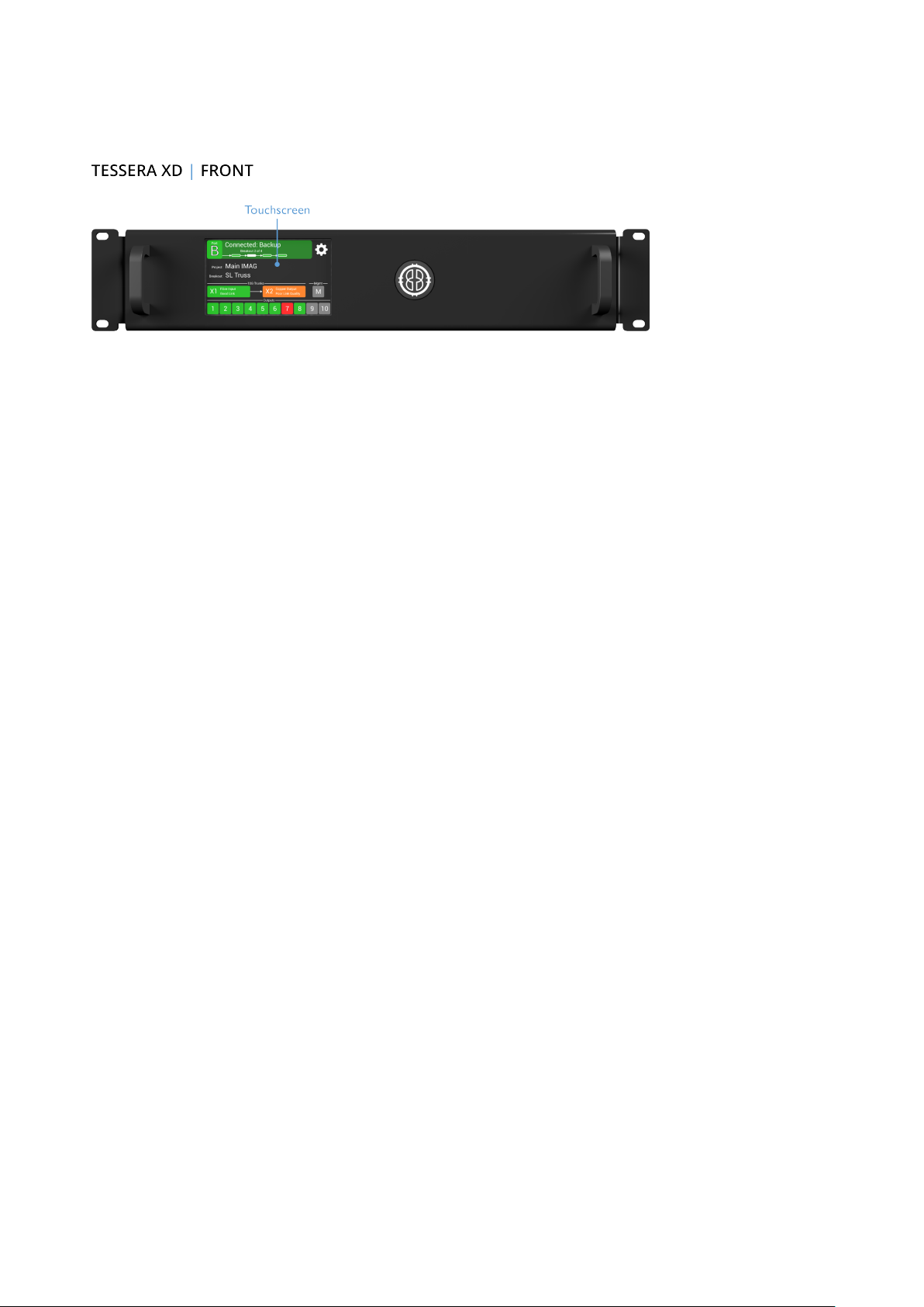
TESSERA XDDISTRIBUTION UNIT
FRONT PANEL
Front Panel Touchscreen
A front touchscreen displays some information for confirmation during setup and troubleshooting. This
includes:
l All Ethernet port link states
l Processor connection state
l The name of the current project open on the Tessera SX40
l XD name for easy identification in largeprojects
The screen orientation and brightness is configurable, and the screen and per-port LEDs may be disabled for
operating in dark environments.
Firmware is reloadable from the Tessera SX40, just as with other Tessera fixtures.
9

REAR PANEL CONNECTIONS
Feature Description
Supports Neutrik EtherCON Cat 6A / etherCON (CAT5e) connectors
Two 10G Tessera Protocol
copper inputs for
connection from Tessera
SX40
Compatible with standard RJ45 connectors
Requires Cat6A cable (up to 60m) or Cat5e cable(up to 30m)
One of the 10G ports can be used as thru connection for daisy-chaining of
additional XDs
Supports Neutrik opticalCON DUO / DUO ARMORED / DUO X-TREME / DUO LITE
connectors
Two 10G Tessera Protocol
fibre inputs for connection
from Tessera SX40 (Single
mode ONLY)
Up to five XDs may be
daisy-chained
Ten 1G Tessera Protocol
outputs for connection to
fixtures
Compatible with standard LC-Duplex connectors
Requires 1310nm, 9/125um single-mode fibre (up to 2KM) with PC or UPC
connectors
One of the 10G ports can be used as thru connection for daisy-chaining of
additional XDs
Auto-switching between fibre and copper
Thru port auto-switches independently from input
Position 1G output ports in multiple locations for cabling convenience
Bandwidth of each 1G port is shared between all daisy-chained XDs
Extend 10G cable lengths using an XD as a signal repeater
Convert between 10G fibre and 10G copper (or vice versa) using an XD as a media
converter
Neutrik etherCON connectors, compatible with standard RJ45
Each 1G output supports a nominal 525K pixels at 8bpc, 60Hz
Pixel capacity per 1G port scales according to selected bit depth and framerate
10

TESSERA M2 LED PROCESSOR
FRONT PANEL
Feature Description
Front panel status LEDs
Press to reset the processor, press and hold to restore to factory settings.
Reset button
2 x USB 2.0 type A ports
Warning, this will delete all project files and fixture packs not included with the base
firmware
To connect USB memory storage devices and peripherals e.g. keyboard and
mouse
FRONT PANEL STATUS LEDS
LEDName Indication
Active
Ethernet The processor is detecting a network connection
DMX In A DMXSignal is being received by the processor
Video In The processor is connected to a valid video input source
Reference In The processor has a valid source of genlock connected to the reference input connector
Tessera Out The processor is connected to fixtures
Black/Freeze Either the blackout or freeze button has been enabled
Overtemp
On: Processor in operation
Blinking: Processor booting up
Off: Processor in normal operating temperatures
Blinking: Processor overheating but operational
On: Processor overheated and shutdown
11

REAR PANEL CONNECTIONS
Feature Description
Connect a PC or Mac running the Tessera Remote, Tessera Control application or
Management Ethernet
Local User Interface
DVI Input
Reference Input Used for analog bi-level or tri-level sync.
3G-SDI Input
Loop Thru Ports All video inputs and syncs have re-clocked loop thru ports.
Gigabit Ethernet Outputs
DMX 512-A Input For DMX real-time control.
On/Off Switch
IEC Mains Input The input is auto ranging from 100-250v/47-63Hz
an eDMX protocol directly to the local data Gigabit Ethernet port. The two ports
work as a switch to daisy-chain units.
The M2 processor can be operated locally with a monitor connected via
DisplayPort. Peripherals such as mouse and keyboard can be connected to the
USB ports on either the front or rear panel.
A DVI input of up to 1920x1080 @ 60Hz (148.5MHz pixel clock) is supported. This
is a DVI-I input which supports DVI-D, VGA/ RGBHV and Component Analogue
(YPbPr) with a suitable adapter. See “Canvas Resolutions” on page 42 for more
info.
Two 3G-SDI inputs are available. Both inputs can be used concurrently as an
independent input. The SDI inputs support 3G-SDI level A or level B. Both inputs
can be used together to support Dual Link HD-SDI.
3G-SDI accepts progressive and interlaced signal of up to 1920x1080 resolution at
23.98Hz to 60Hz framerate with 10 bits per channel colour depth.
The M2 processor has four 1 Gigabit Ethernet outputs which are provided on
EtherCON connectors. Fixtures must be connected using Gigabit Ethernet cable
(Cat-5e or above). See “System Configuration” on page 21 for more info.
The processor can be shut down from the local interface or remote computer. No
harm will result from turning the processor off at the switch.
12
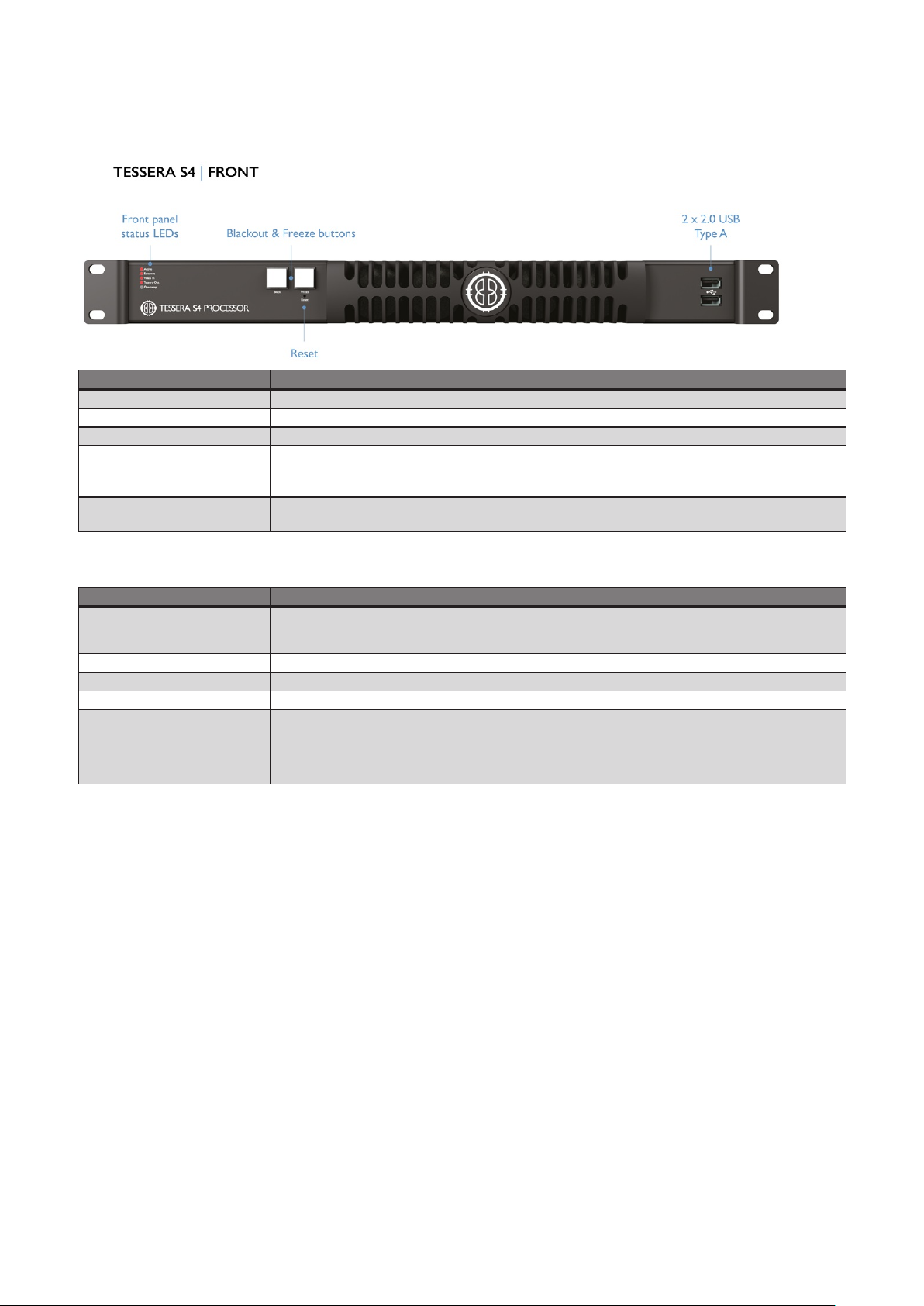
TESSERA S4 LED PROCESSOR
FRONT PANEL
Feature Description
Front panel status LEDs
Black button Sends the output of the processor to black
Freeze button Freezes the output of the processor
Press to reset the processor, press and hold to restore to factory settings.
Reset button
2 x USB 2.0 type A ports
Warning, this will delete all project files and fixture packs not included with the base
firmware
To connect USB memory storage devices and peripherals e.g. keyboard and
mouse
FRONT PANEL STATUS LEDS
LEDName Indication
Active
Ethernet The processor is detecting a network connection
Video In The processor is connected to a valid video input source
Tessera Out The processor is connected to fixtures
Overtemp
On: Processor in operation
Blinking: Processor booting up
Off: Processor is in normal operating temperatures
Blinking: Processor is overheating but operational
On: Processor overheated and shutdown
13

REAR PANEL CONNECTIONS
Feature Description
Management Ethernet
Local User Interface
DVI Input
Gigabit Ethernet Outputs
On/Off Switch
IEC Mains Input The input is auto ranging from 100-250v/47-63Hz
Connect a PC or Mac running the Tessera Remote, Tessera Control application or
an eDMX protocol directly to the local data Gigabit Ethernet port.
The S4 processor can be operated locally with a monitor connected via
DisplayPort. Peripherals such as mouse and keyboard can be connected to the
USB ports on either the front or rear panel.
A DVI input of up to 1920x1080 @ 60Hz (148.5MHz pixel clock) is supported. This
is a DVI-D input, with a re-clocked DVI-D thru. See “Canvas Resolutions” on page
42 for more info.
The S4 processor has four 1 Gigabit Ethernet outputs which are provided on
EtherCON connectors. Fixtures must be connected using Gigabit Ethernet cable
(Cat-5e or above). See “System Configuration” on page 21 for more info
The processor can be shut down from the local interface or remote computer. No
harm will result from turning the processor off at the switch.
14

TESSERA T1 LED PROCESSOR
FRONT PANEL
Feature Description
Front panel status LEDs
Press to reset the processor, press and hold to restore to factory settings.
Reset button
2 x USB 2.0 type A ports
FRONT PANEL STATUS LEDS
LED Name Indication
Active
Ethernet The processor is detecting a network connection
DMX In A DMXsignal is being received by the processor
Video In The processor is connected to a valid video input source
Tessera Out The processor is connected to fixtures
Black/Freeze Either the blackout or freeze button has been enabled
Warning, this will delete all project files and fixture packs not included with the base
firmware
To connect USB memory storage devices and peripherals e.g. keyboard and
mouse
On:Processor in operation
Blinking:Processor booting up
Off:Processor is in normal operating temperatures
Overtemp
Blinking: Processor is overheating but operational
On: Processor overheated and shutdown
15

REAR PANEL CONNECTIONS
Feature Description
Management Ethernet
Local User Interface
DVI Input
DMX 512-A Input For DMX real-time control.
Gigabit Ethernet Outputs
On/Off Switch
IEC Mains Input The input is auto ranging from 100-250v/47-63Hz
Connect a PC or Mac running the Tessera Remote, Tessera Control application or
an eDMX protocol directly to the local data Gigabit Ethernet port.
The T1 processor can be operated locally with a monitor connected via
DisplayPort. Peripherals such as mouse and keyboard can be connected to the
USB ports on either the front or rear panel.
A DVI input of up to 1920x1080 @ 60Hz (148.5MHz pixel clock) is supported. This
is a DVI-D input, with a re-clocked DVI-D thru. See “Canvas Resolutions” on page
42 for more info.
The T1 processor has one 1 Gigabit Ethernet output which are provided on
EtherCON connectors. Fixtures must be connected using Gigabit Ethernet cable
(Cat-5e or above). See “System Configuration” on page 21 for more info
The processor can be shut down from the local interface or remote computer. No
harm will result from turning the processor off at the switch.
16
CHAPTER 3 - QUICKSTART
Follow this chapter to get a basic system up and running. This guide covers starting a new project with fixtures
connected. To set up a project offline and connect fixtures at a later stage, see “Tessera Management
Software” on page 30 for more info.
TESSERA PROCESSOR SETUP
1. a. M2, T1 and S4 users: Connect fixtures to the Tessera output ports on the rear panel of the
processor using Gigabit Ethernet cable (Cat 5e or above) and network switches.
b. SX40 users: Connect the XD unit to the processor using either copper or fibre optic cables.
Fixtures are required to be connected to the XD unit.
Note - Tessera SX40 processor does not feature support sub-fixtures. Tessera
firmware version 2.3 will introduce support for sub-fixtures.
2. Connect the video input source(s) to the DVI, HDMI and/or SDI input ports.
3. Connect a monitor to the Local UI using the DisplayPort connector and connect a mouse and keyboard.
Alternatively, access the processor's user interface through a Mac or Windows PC running the Tessera
Remote application.
4. Connect the IEC mains input and switch the processor on. When the processor has powered up, the
monitor displays the start screen. By default, the processor is configured to automatically load the
previous project after a set amount of time if the user does not intervene.
Figure3-1 . The Start Screen
17

TESSERA PROJECT SETUP
1. From the Start Screen, select New to launch the Project Wizard.
Figure3-2 . The New Project Wizard
2. The project name can be manually entered, if no entry is made, a default project name containing the
processor’s model with a date and time stamp is assigned.
3. Select a canvas size from the drop-down menu. When selecting a resolution other than the native
1920x1080, Tessera M2 and T1 processors enforce Low Latency Mode.
4. Click Create to be taken to the Main Project Screen.
5. The project is saved to the processor’s internal storage. When using Tessera Remote, project files are
also saved to the connected computer.
Figure3-3 . Main Project Screen
18

CONNECTING FIXTURES
Figure3-4 . Add Fixtures from Network button
1. Ensure that all fixtures are connected to the processor with the desired topology, taking into
consideration the output port’s capacity limit.
2. Click the Add Fixtures From Network button. The canvas toolbar is replaced with a row of currently
connected fixtures. When using Add Fixtures From Network, strings of fixtures are highlighted with
colours corresponding to the ones shown in the UI. Each string is assigned a unique numeric code which
appears on the first fixture of the string during association.
Figure3-5 . The Add Fixtures From Network toolbar, the right-side shows connected fixtures whilst in Add Fixtures
From Network menu.
3. Entering this code on the processor (using number keys or numpad) selects the corresponding string for
association. The string is then ready to be drawn in the canvas using the cursor.
Figure3-6 . Associat ing Fixtures
Figure3-7 . A highlighted Recoloured string
4. The first fixture in the string is highlighted white, while other fixtures display varying shades of the same
colour to denote the order of the fixtures in the string - from brightest to darkest.
5. Click on the canvas to add fixtures one by one. The currently selected fixture is highlighted in white on
the LED panel.
19

6. Clicking and dragging will draw an array of fixtures. The topology is defined by the direction taken when
drawing the array.
7. Repeat the process for all strings, then press Enter or click the Back arrow to return to the Main Project
Screen.
8. Fixtures on the canvas display a green circle to indicate online status. If the input source is connected,
the fixtures will output video.
20
CHAPTER 4 - SYSTEM CONFIGURATION
CONNECTING FIXTURES
Tessera processors drive Tessera compatible devices. Tessera compatible fixtures are fitted with an Tessera
receiver card inside, either in each tile or cabinet, or in a root node connected to strings of sub-fixtures.
All Tessera compatible fixtures have two gigabit Ethernet ports: one to connect to the processor and one to
connect to the next device in the chain. These ports are interchangeable for convenience.
The processor communicates with fixtures on the network using the Tessera protocol. The system topology
requires fixtures to be connected to the HD processor or XD distribution unit. Once connected, a group of
fixtures in a daisy-chain becomes a string.
Note - Tessera Protocol only supports gigabit ethernet compliant equipment and does not
function with 100BASE-T (Fast Ethernet) or 10BASE-T.
The 10 gigabit connection between the XD and SX40 processor must be direct, using fibre
optic or Cat6a or above cabling.
See "Cable Requirements For Tessera SX40 and XD" on page 177.
CONNECTION GUIDELINES
1 GIGABIT DATA CONNECTION
Tessera devices need to be connected to the HD processor or XD unit directly or via a gigabit ethernet network
switch, using cables that conform to Cat 5e or above and include RJ45 and EtherCON terminations.
The maximum supported individual cable length is 100 meters. The Tessera protocol can be transmitted over
standard gigabit ethernet compliant fibre optic hardware for single runs exceeding this distance.
The suggested maximum number of nodes between the processor and the furthest fixture in any system is
five switches and 50 fixtures (XD units and fibre optic transceivers count as switches). By using switches, up to
500 fixtures can be run from a Tessera processor output port (assuming this does not exceed the pixel limit of
the output).
Note - The Tessera Protocol does not support connection over Wi-Fi due to the bandwidth
required to alter content and fixtures.
10 GIGABIT DATA CONNECTION
The connection between the SX40 processor and the XD distribution units needs to be direct by using singlemode fibre-optic cables with PC or UPC DUO connectors for a length of up to 2Km or Cat6a or above cabling
with RJ45 or EtherCON terminations to reach a maximum distance of 60m.
21

REDUNDANCY CONFIGURATION
CLOSED LOOP REDUNDANCY
Closed loop redundancy is supported on Tessera SX40, M2 and S4 LED processors where two outputs can be
configured to operate as a redundant pair. Closed loop redundancy is not supported on Tessera T1 LED
processors as they only feature a single output.
For the Tessera M2 and S4processors with closed loop redundancy, a cabling loop is created from the primary
port, through a string of fixtures, and then back to the processor. One output acts as the primary port, while
the second output acts as the backup. In the case of signal loss or errors with the primary feed, the backup
port takes control and re-allocates fixtures to use the backup feed. The changeis done within one frame,
ensuring live content continues to display in the event of failures occurring anywhere in the loop.
Figure4-1 . Tessera processor setup with redundancy
The load capacity for each redundant pair is the same as for a single non-redundant port. Redundancy is only
available from port 1 to port 2, and from port 3 to port 4.
Once the system has been cabled correctly, click on the Network pipeline tile. Under redundancy the user can
enable redundancy for connected ports. The processor is also able to detect faults with cabling and reports
Loop OK or Errors Detected for connected ports.
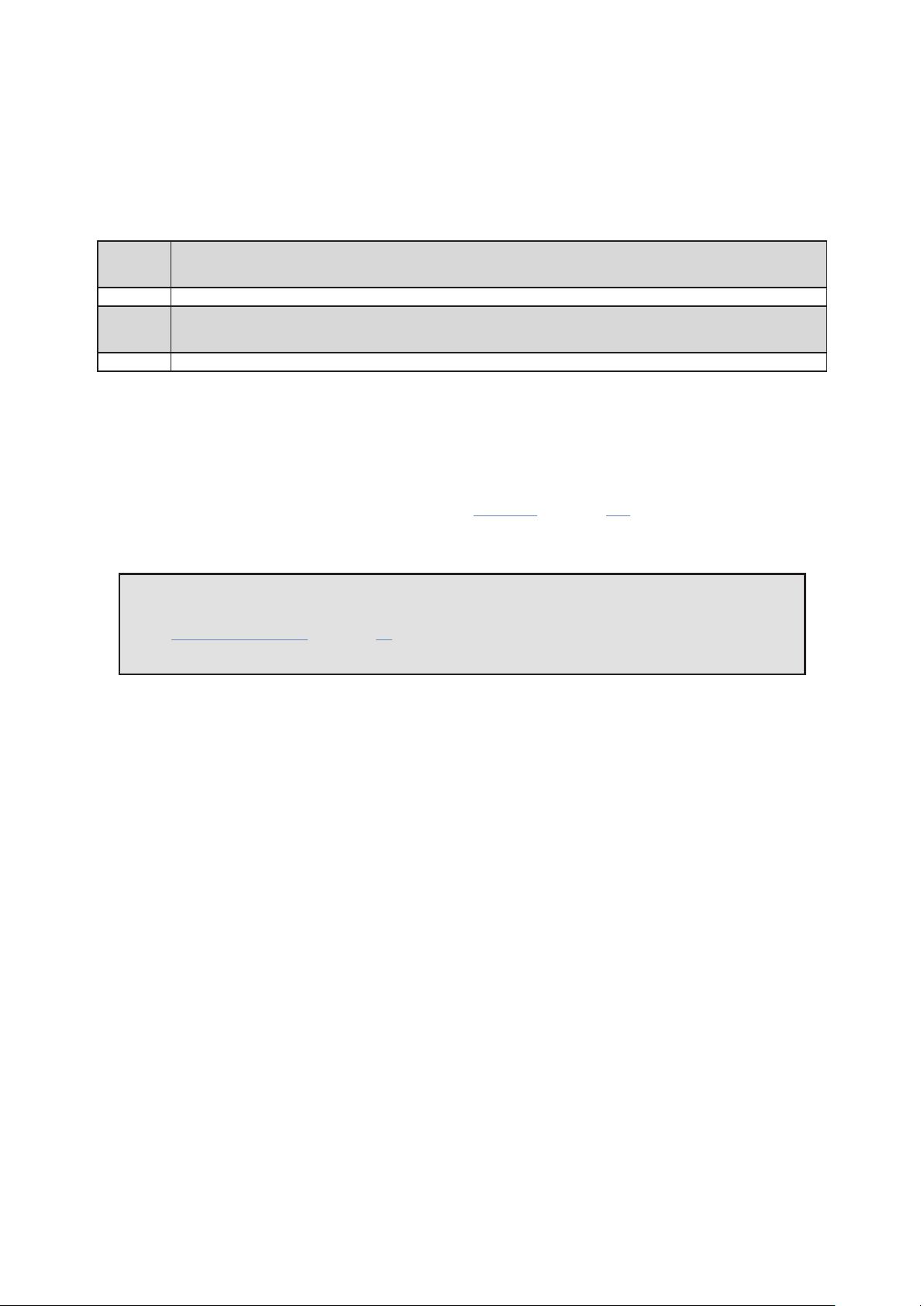
For Tessera SX40 processor, loop redundancy is created between two trunks, from A to B and C to D. For more
information see on page 24
22
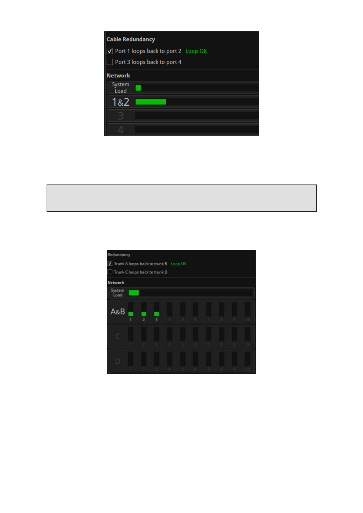
Figure4-2 . Redundancy options on the Network tab for Tessera processors
The Network tab includes the loop status indicator and a load bar for a redundant output pair on ports 1 and
2. Ports 3 and 4 continue to operate independently without redundancy.
Note - The system load will double when redundancy is enabled, this is because twicethe
amount of bandwidth is needed to ensure primary and backup signals are maintained.
In the Tessera SX40, 10Gb trunk pairs can be (independently) configured for redundant operation (A+B, C+D)
however symmetry must be maintained.
Figure4-3 . Tessera interface with redundancy configured on trunks A and B
Fixture chains must be connected to the same port of the same XD on both primary and backup trunks. XDs
aremirrored on the backup trunk.
23

Figure4-4 . Tessera SX40 configured with redundancy for trunks A and B and C and D
When operating in redundancy mode:
l Fixtures can be cabled in a singlechain of up to 50 fixtures, with each end of the chain connected back
to the processor (or Tessera XD when using a Tessera SX40). Ethernet switches must not be used to split
the signal. Other Ethernet hardware (such as fibre extenders) are supported.
l Closed loop redundancy should be enabled on the processor.
l The output capacity limits that apply to a single port also apply to the pair of ports. This effectively
halves the overall processor capacity, as each output signal is being 'doubled up'. This also applies to
Tessera SX40, therefore twice the amount of XD units would be required.
l The total network load for the two ports combine into a single bar indicating the load for that pair.
l Switching in and out of redundancy mode will momentarily black-out the video signal for all connected
fixtures on all ports. Redundancy mode should be configured in advance.
l The active feed (primary or backup) used by each fixture can be viewed in the Online tab.
l If both the primary and backup signals are operational, each fixture can alternate between either signal.
If a fixture receives a video error or complete signal loss from one port, it will switch to the backup port
for the next frame.
l For Tessera M2/T1/S4 LED processors, each loop must be cabled between the two adjacent ports on the
same processor. (I.e. Port 1 to Port 2, and Port 3 to Port 4.)
l For Tessera SX40, the loop is created using the same trunk port number in two adjacent XD units (i.e.
Trunk A to Trunk B, and Trunk C to Trunk D)
24

PROCESSOR REDUNDANCY
Only available for the Tessera SX40, processor redundancy is designed as a backup system should the primary
processor fail to send a signal to the fixtures. If the primary processor stops outputting video signal, the
backup processor will detect the fault and re-associate fixtures. Fixtures will losevideo signal momentarily and
will automatically resume within 1-2 seconds.
Different types of failure can trigger failover including; power issues, closing project, loss of input signal, fixture
data cable disconnection, processor failure, or if failover is activated by the user.
To set up processor redundancy:
1. Connect the primary and backup processor to the X1 and X2 ports of the XD units.
2. Enable failover in the failover tab of both processors.
3. Select the role of each processor, either primary or backup.
4. Different criteria can be set for auto-failover behaviour:
l If the primary processor fails for (x) seconds
The backup processor takes control if the primary processor’s Tessera output is missing for (x)
seconds
l If the primary video source is lost for (x) seconds
The backup processor takes control if the primary processor’s video feed is missing for (x)
seconds
l If both front panel buttons are pressed together
Failover can be triggered manually by pushing both front panel buttons at the same time
l Always prefer primary if available , auto-failover back to the primary processor whenever it
becomes available
5. Video input cabling
o
Both processors may be fed from the same video source if required. HDMI/SDI thru can be used
but isn't recommended; an upstream splitter is preferable.
o
Each processor may be fed from a completely independent video source if required. These may
be different formats (HDMI/SDI), resolutions, framerates, etc. - there's no requirement for any
aspect of the sources to match.
o
External reference signals (if in use) may similarly be shared or independent between the two
processors.
6. Both processors must be set up independently of each other. Set the project in both processors to
display the desired image. Settings such as fixture position in the canvas, video input and colour
correction can be modified independently, so precautions should be taken to avoid differences between
processors. Using the same settings with the samevideo source is advised. It is a good practice to use
the same show-file in both processors, making sure that one is set as primary and the other one as
backup.
25

Figure4-5 . Processor redundancy
Processor redundancy is compatible with closed loop redundancy, offering different setup possibilities based
on the system requirements.
Figure4-6 . Tessera SX40 LED processor and loop redundancy
26

OUTPUT CAPACITY
The Tessera output port capacity depends primarily on the network bit depth and frame rate. The nominal
pixel capacity per port is outlined in the table below:
Refresh/Bit Depth 8 bit 10 bit 12 bit
24hz 1,312,500 1,050,000 875,000
25hz 1,260,000 1,008,000 840,000
30hz 1,050,000 840,000 700,000
50hz 630,000 504,000 420,000
60hz 525,000 420,000 350,000
OTHER FACTORS AFFECTING OUTPUT CAPACITY
Fixture Rotation
Rotating fixtures on-axis (i.e. by 0°, 90°, 180° or 270°) has no effect on the output capacity.
However, each fixture rotated off-axis is counted twice towards the output capacity.
27

Mapping Mode For Projects With Multiple Fixtures
The M2 and T1 processors can use different mapping modes to fit the project’s necessities. The SX40 and S4
always work with 1:1 mapping.
1:1 mapping doesn’t affect the output capacity. This mode sends the pixels of the input to the fixtures
without taking into consideration the fixture size, only the pixel number.
When using interpolated mapping, the content on fixtures with a coarser pixel pitch is scaled so that the
content appears the samesize across all fixtures. In this mode, all fixtures are assumed to have the same pixel
pitch as the finest fixture, and the output capacity is calculated according to the physical dimensions of the
fixture.
See “Mapping Options” on page 43 for more information.
Small Fixtures
Small fixtures - with either dimensions smaller than 16 pixels - have a high processing overhead. Therefore, the
number of these fixtures supported may be fewer than that calculated from the nominal pixel capacity.
In terms of processing, the SX40 processor considers any connected fixture to be at least 64px in either
dimension, so the total number of fixtures per port might be affected.
Estimating Fixture Capacity
When associating fixtures to a project, network load bars display the output capacity on each port. The UI
updates in real time as settings such as network bit depth, genlock frame rate and fixture rotations are applied.
See “Network” on page 142 for more information.
Figure 4-7. Network property editor showing system load and port load
To help with estimating the number of processors required for a project, we have created a simple web-based
calculator tool which models all the factors outlined above. For further details, please contact support at:
support@bromptontech.com
28
COMBINING PROCESSORS
The Tessera T1, S4, M2 and SX40 processors are designed to be used together in a configuration without
issues. Different types of processors can be used to run different sections of the same wall.
When combining processors, to avoid tearing, it is important to synchronize them by matching their end to end
delay and genlocking the sources.
The end to end delay of the different processors is:
T1
S4 2 frames (this processor is always in low latency mode)
M2
SX40 2 frames (this processor doesn't have low latency mode)
When working with different types of processors, the video latency requires re-adjusting per processor.
I.e. If using T1 and SX40 processors together, a frame of latency will have to be added to the SX40 processors,
initially with 2 frames latency, to match the 3 frames of latency of the T1.
The processors need to be genlocked to the same source or to each other.
For more information about video delay and genlock, see “Network” on page 142.
3 frames
2 frames in low latency mode
3 frames
2 frames in low latency mode
Note - Please note that the difference in features between processors still apply. The SX40
does not have Low Latency mode but the scaler is disabled when using custom resolutions.
See “Low Latency Mode” on page 43 for more details in the limitations when working in Low
Latency mode.
29

CHAPTER 5 - TESSERA MANAGEMENT SOFTWARE
The Tessera Management Software is used to configure and control all aspects of Tessera Processors. The user
interface can be accessed in two ways – locally with the use of a monitor, mouse and keyboard, or remotely
using the Tessera Remote application.
The user interface is consistent across both access methods, with only subtle differences in functionality.
LOCAL USER INTERFACE
When using the local user interface on the processor itself, no external computer is required.
To view the user interface, connect a monitor to the local UI port on the rear of the processor. DisplayPort
monitors are natively supported, other connection types require an adapter. Once connected, the native
resolution of the monitor is automatically detected. To change the default resolution, navigate to Settings >
Processor, select a resolution from the dropdown menu and click Commit. The minimum supported resolution
for M2, T1 and S4 processors is 1024x768 and the maximum resolution is 1920x1080. Tessera SX40
processor supports UIresolutions of up to 3840x2160.
The user interface is controlled by connecting a mouse and keyboard to the processor’s USB ports.
TESSERA REMOTE AND OFFLINE EDITOR
Tessera Remote is a Windows PC and Mac OS application that allows remote control of Tessera processors
across a network. Additionally, the Remote application can be used as an ‘offlineeditor’ allowing the set up and
editing of Tessera projects when not connected to a processor.
The main difference in functionality when working with the Tessera Remote app (not offline) is that the video
on canvas edit modes are not available.
Tessera Remote is free to download from the Brompton Technology website:
http://bromptontech.com/support
Note - Tessera Remote software versions and the processor firmware versions must match.
If the processor firmware version and Tessera Remote do not match, the firmware or remote
software must be updated. The processor firmware can be updated from the remote app.
30

INSTALLATION FOR WINDOWS PC
1. Download Tessera Remote Windows software from https://www.bromptontech.com/support
2. Open the downloaded file to begin Setup Wizard. Hit Next to continue.
3. The setup wizard gives options to create shortcuts for your computer and whether to associate relevant
files to the application.
31

4. The setup wizard asks for an install location, once selected click Next to begin the installation.
5. When the application has finished installing, a completion dialog box is displayed. Tick the ‘Run Tessera
Remote’ box to launch the application after clicking Finish.
32

INSTALLATION FOR MAC OS X
1. Download Tessera Remote Mac OSX installation file from Brompton’s website
https://www.bromptontech.com/support
2. Double click the .dmg file and drag the Tessera Remote icon into the Applications Folder, or copy (⌘ + C)
and Paste (⌘ + V) the Tessera Remote icon into the Applications folder
3. Multiple software versions of Tessera Remote Application can be installed on the same Mac computer. It
can be helpful to store these in different folders within the Applications folder.
NETWORK SETTINGS FOR REMOTE MANAGEMENT
To connect a computer to a Tessera processor, connect to the same network via Ethernet by setting the
computer and processor to the same subnet mask and IP range. As the Tessera processor’s remote network
port supports Auto MDI-X, this network can be as simple as using a Cat 5e cable connected to the Mac or
Windows PC without the need for a switch.
The default IP settings for the processor are 192.168.0.50, with a subnet mask of 255.255.255.0.
For further details on setting IP addresses on Windows and Mac OS, see "Setting IPAddresses" on page 179.
Note - Due to the bandwidth limitations and reliability, wireless connections are not
supported within the Tessera systems.
33

CONNECTING TO A TESSERA PROCESSOR
Having physically connected a Mac or Windows PC to a Tessera processor via network, launch the Tessera
Remote application. This will open a dialogue box to start Tessera Remote or the Offline Editor.
Figure5-1 . Start up menu f or Tessera Remote
Click ‘Start Tessera Remote’ to start the application in Remote mode.
The application automatically detects connected processors on the network. Note the Tessera Remote
software version. If it does not match the processor firmware version, reload processor firmware or install a
matching Tessera Remote software version.
Figure5-2 . Tessera Remote main menu with processor select options.
When reloading processor firmware, the processor is temporarily inaccessiblewhile firmware is written to the
processor. Once this process is complete, the processor will reboot before becoming accessible again.
Discovered processors display the following details:
l User-defined name of the processor
l Firmware version
l Processor type
34

l IP address
l Project file that is currently in use
To connect to the processor, double click the processor, or select a processor and click Connect.
TESSERA REMOTE SETTINGS
The Tessera Remote offline mode Settings menu contains preferences which allow general customisation of
the canvas, fixture packs management and selection settings within Tessera Remote. These settings are stored
locally and not applied to the processor itself.
Figure5-3 . Tessera Remote s ettings menu
Once connected to the processor, the Remote application functions in a very similar way to the local user
interface. For further detail about the Settings, see “Processor Settings” on page 155
When Tessera Remote is connected to the processor, the Local Management app running on the processor
cannot be used. Take control of the processor by clicking the Take Control icon.
DISCONNECTING FROM THE PROCESSOR
When closing the app or disconnecting from the processor, several options can be selected.
Closing the app:
Figure5-4 . Tessera Remote, closing the app options
35

Disconnecting from the processor:
Figure5-5 . Tessera Remote, disconnection from processor options.
l Clicking “Leave the project open on the processor” will return control to the processor’s local UI while
keeping the project open.
l Clicking “Close the project on the processor” returns control to the processor’s local UI and closes the
current project. The user will see the project management screen on the local UI.
l Clicking “Disconnect from the processor” returns control to the processor’s local UI.
l Clicking “Shutdown the processor” will shutdown the processor remotely. It will disappear from the
network and won’t be accessible to the user however it will need to be powered down locally. The
message “It is now safe to switch off the processor” is shown. A reboot button is located underneath
this message if the user requires a reboot.
Figure5-6 . Processor shutdown screen
OFFLINE EDITOR
When using Tessera Remote in Offline Editor mode, the user can modify projects without a processor. Offline
Editor allows the user to create new projects, open previously created projects, or import projects from
another location.
Drawing panels on the canvas using the “Add Fixturefrom Library” tool and other features are also available
but limited until connected to a processor. See “Creating A New Project in Offline Editor” on page 41 and
“Add fixtures from library” on page 58 for more details.
36

MULTIPLE PROCESSOR CONTROL
There are different approaches to control multiple processors:
Use a single Tessera Remote instance - It is easy to connect and disconnect from different processors on
a network. Theoutput from the processors will continue uninterrupted when Tessera Remote is not
connected.
Use multiple Tessera Remote instances - Although Tessera Remote only supports connection to one
processor at a time, it is possible to run several instances of Tessera Remote on the same computer for remote
control of several processors from one device.
Use the Tessera Control application - Tessera Control provides a simple user interface for controlling
multiple processors simultaneously. Controls available include Global colour, input colour and presets. See
"Tessera Control" on page 154 for more information.
Use DMX and eDMX Control – Several control profiles are available and can be customised to control
adjustments in colour, position, rotation, presets, etc. See " DMX Control" on page 152 for more information.
RUNNING MULTIPLE INSTANCES OF TESSERA REMOTE
When controlling multiple processors from one computer it is recommended to use a fixed IP address on each
processor and on the computer running Tessera Remote. It can also be helpful to name each processor. See
the section "Identification" on page 156.
Controlling different processors is then as straightforward as ‘tabbing’ (Alt + Tab in Windows, ⌘ + Tab in Mac
OSX) to the relevant instance of Tessera Remote as required. Several monitors can also be used to control
different instances at the same time.
Note - MacOSX - To start Tessera Remote so that multiple instances can be run it is
necessary to run Terminal in Utilities.
In Terminal, type: open /applications/remote.app then press Enter.
To run another instance of Tessera Remote type the following into Terminal:
open -n /applications/remote.app
Figure 5-7. Alt-Tab to monitor or swtich through multiple instances of Tessera Remote
37
CHAPTER 6 - PROJECT SETUP
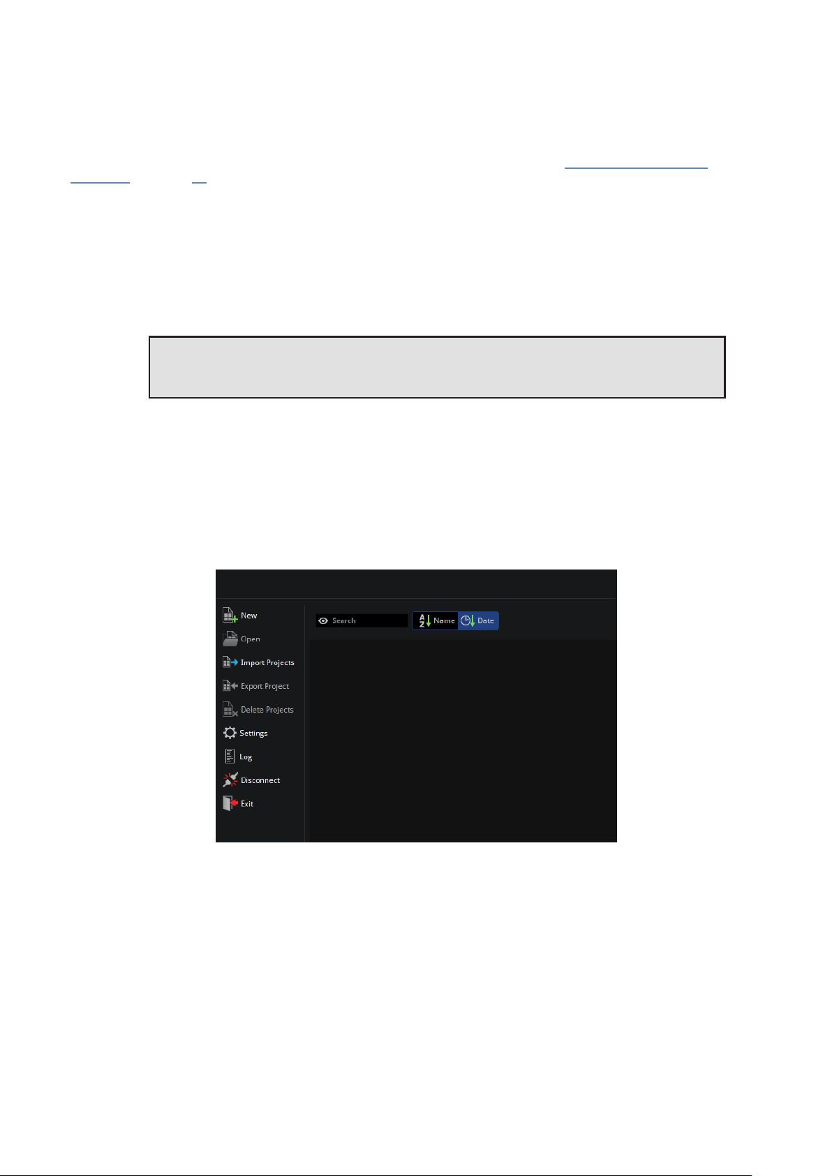
PROJECT MANAGEMENT
OPENING AND IMPORTING PROJECTS
Select a project from the list then click Open from the left menu. You can also import projects from USB drives
or the local computer storage drive.
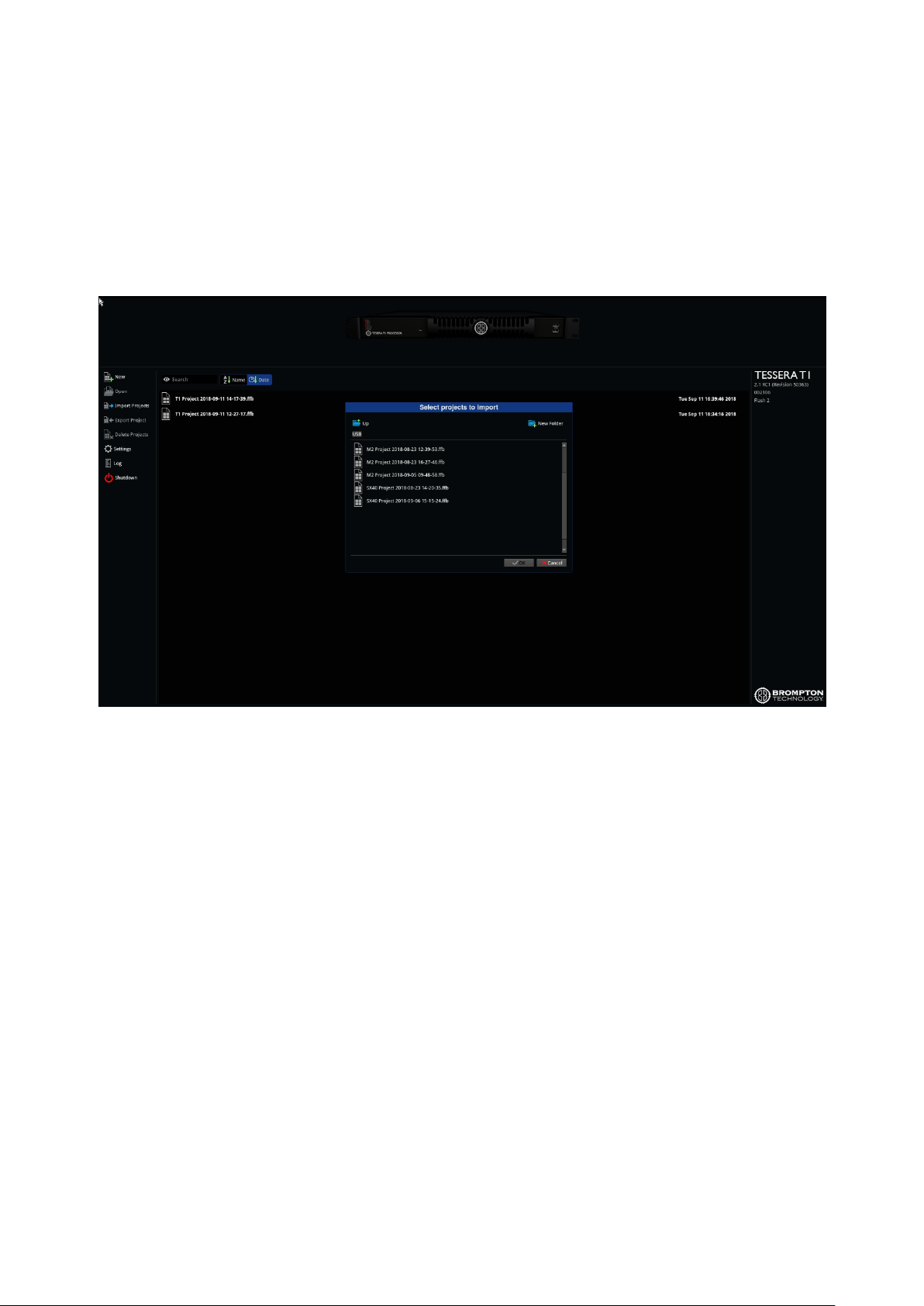
Figure6-1 . Importing projects in the project management screen
To import a project using the processor:
1. Insert a USB flash drive containing the project file into a USB port of the processor.
2. Click Import Projects on the project management screen to display the File Browser.
3. Navigate to a project file, select and click OK. Theproject file is copied and displayed in the list of projects
stored on the processor.
4. Double click the file to open it.
To import a project while connected to the processor via Tessera Remote:
1. Click Import Project to open a file browser window and navigate to the project file stored on the
computer.
2. Select the file and click OK. The project file is copied to the list of projects stored on the processor.
38

EXPORTING PROJECTS
In the remote app, to export a project stored in the processor, select the desired project from the project
management screen and click Export project to select the location.
When a project is open, pressing Save as... is used to create a copy of the project and set it as the active project.
Save a copy, creates and saves a copy of the project to the computer whilst keeping the current project open
for editing.
Figure6-2 . Exporting projects in the project management window.
In the Local user interface, projects can be exported to a USB drive.
1. Insert a USB flash drive into a USB port of the processor.
2. Click Export project on the project management screen to display the file browser.
3. Navigate to the desired location, make selection and click OK.
DELETING PROJECTS STORED ON THE PROCESSOR
1. From the project management screen, click to individually select projects and click Delete Projects to
remove the file.
2. To delete multiple projects, hold Ctrl and use the mouse cursor to select multiple files.
39

CREATING A NEW PROJECT ON LOCAL UI AND TESSERA REMOTE
Figure 6-3. The New Project Window
To start a new project, select New on the project management screen. Once the New Project Wizard launches:
1. Enter a project name
2. Select a canvas size, Low Latency modeis automatically enabled on Tessera T1 and M2 LED processors if
canvas sizes other than 1920x1080 are used.
3. The Tessera SX40 features custom resolutions, see “Custom Canvas Resolution” on page Custom
Canvas Resolution for more information.
4. Seam Brightness, Module Colour correction, Low Latency Mode, and Loop/Processor Redundancy can
be enabled from this menu.
5. Click Create to move to canvas edit mode.
The project is automatically saved to the processor’s internal storage but can also be saved to a USB storage
device. See "Project Management" on page 38 for more information.
40
CREATING A NEW PROJECT IN OFFLINE EDITOR
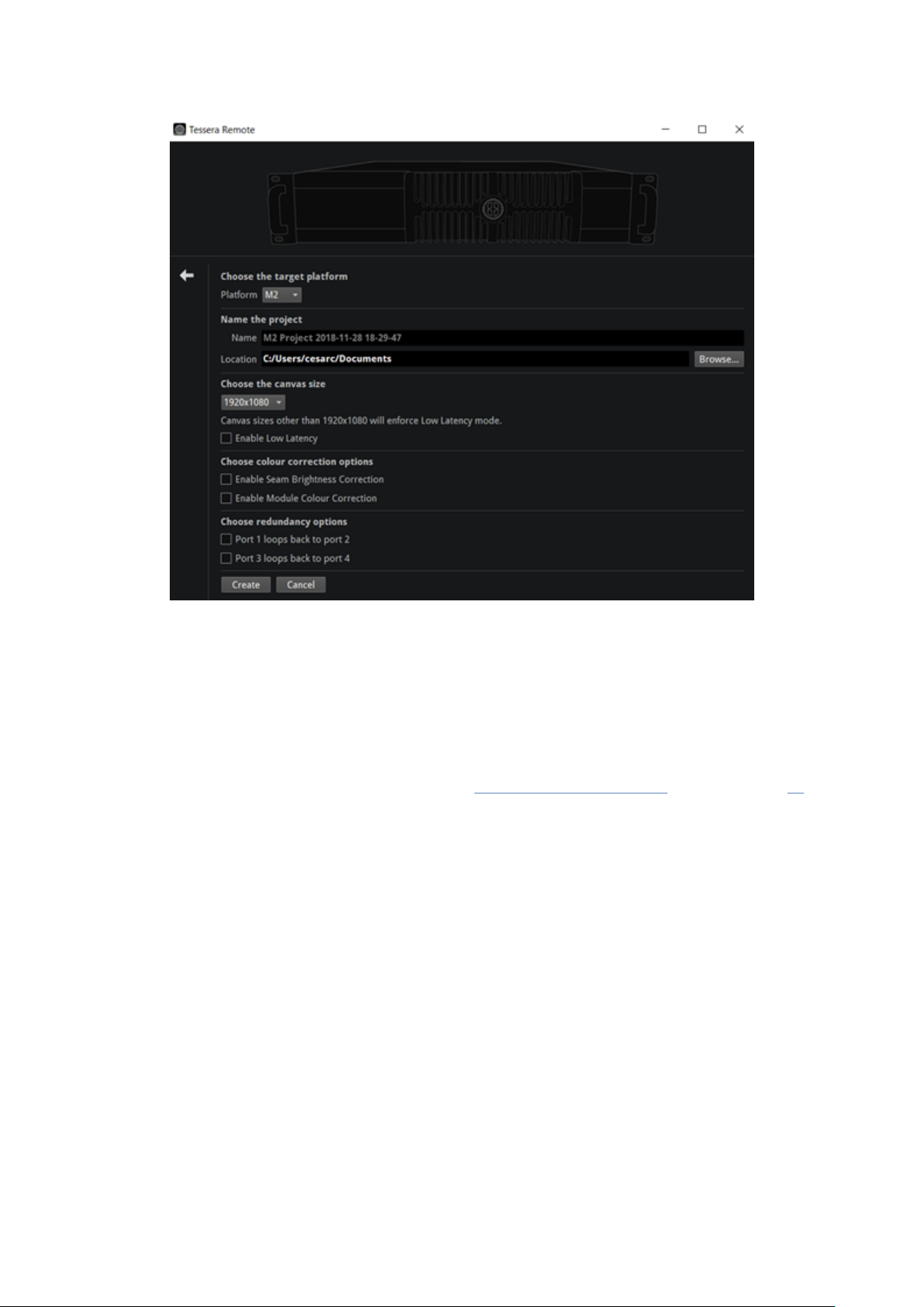
Figure6-4 . The off line editor’s New Project Wizard differs from Remote and Local UI mode
To start a new project, select New from the menu on the Main screen. Once the New Project Wizard launches:
1. Select the processor platform where the project is to be used.
2. Enter a project name and the location for the project file to be saved to.
3. Select a canvas size, Low Latency Mode is automatically enabled on Tessera T1 and M2 LED processors if
canvas sizes other than 1920x1080 are used.
The Tessera SX40 features custom resolutions, see “Custom Canvas Resolution” section on page 42 for
more information.
4. Seam Brightness, Module Colour Correction, Low Latency Mode and Loop or Processor Redundancy can
be enabled from this menu.
5. Click Create to move to canvas edit mode.
41

CANVAS RESOLUTIONS
Tessera systems allow the source to send any input resolution that fits within the canvas size, except when
working at 2880x720 or 720x2880 in the HD processors.
Tessera M2/S4/T1
l The native canvas size for processors is 1920x1080 pixels
l The following list of non-standard canvas sizes are allowed, but places the processor in Low Latency
Mode. See “Low Latency Mode” on page 43 for more information.
l 1080x1920
l 1600x1200
l 2880x720 – This resolution requires the input to match the canvas size
l 720x2880 – This resolution requires the input to match the canvas size
Tessera SX40
l HD1920x1080
l DCI (4096x2160) or UHD (3840x2160) can be selected as native resolutions.
l Custom canvas resolutions are available. The scaler function is disabled.
Custom Canvas Resolution
Only available for the Tessera SX40, the user can enter a canvas size of their choosing, unrestricted by aspect
ratio.
Figure6-5 . The Canvas properties, the user can adjust the canvas size on the f ly
There are some rules to bear in mind when using custom resolutions.
l The scaler function is disabled
l Width:
l Minimum: 720 pixels
l Maximum: 4094 pixels
l It must be an even value
l Height
42

l Minimum: 720 pixels
l Maximum: 4095 pixels
l The maximum total number of supported pixels is 8,847,460
Custom resolution settings should be thoroughly tested before being used in a production environment.
LOW LATENCY MODE
Low Latency Mode reduces the overall latency by one frame.
Tessera T1 and M2 LED processors work at a latency of 3 frames. In Low Latency Mode, the latency is reduced
to 2 frames. Tessera S4 LED processors are always in Low Latency Mode, and non-standard canvas sizes
automatically switch the Tessera M2 and T1 LED processors into Low Latency Mode.
Note - When using several processors with different end to end latencies to run the same
wall, video delay needs to be modified. See “Combining processors ” on page 29 for more
information.
Working in this mode, the following features are disabled:
l Scaling (upscaling and downscaling). As a result, the active area modifications are disabled
l Deinterlace
l Frame-rate conversion, forcing the processor to lock to the source framerate
Colour functions, such as contrast, brightness and RGB gain remain unaffected. The input source is set at its
default resolution and sync frequency and is positioned 1:1 in the top left corner of the canvas.
The Tessera SX40 LED processor does not have a Low Latency Mode, keeping all its features available at 2
frames latency end to end.
Note - We define latency (video delay) as time between the last cycle of a source frame
appearing on the processor's input, and the first cycle that an LED on a fixture is lit with that
frame.
MAPPING OPTIONS
Interpolation can be activated from the Canvas properties. Tessera projects can be set to work in two different
mapping modes depending on the requirements. See “Canvas Properties” on page 78 for more information.
When working in 1:1, the physical size and pixel pitch is not taken into account, every pixel is sent to the
correspondent position, independently of the fixture size.
In Interpolated mode, the physical size of panels is accounted for, interpolating every pixel to match the size of
different panels, keeping the proportions of the image.
43

Figure6-6 . Fixtureoutput in 1:1 mode
Figure6-7 . Fixtureoutput in Interpolated mode
PORT CAPACITY IN 1:1 OR INTERPOLATED
When using 1:1 mapping, the output capacity is not affected.
In interpolated mapping, the content on fixtures with a coarser pixel pitch is scaled to take the panel size into
consideration, so that content appears the same size across all fixtures.
For example, assume we have a project with three fixture types:
l Type A: 5mm pitch, 500mm x 500mm physical size, 100 x 100 = 10,000 pixels
l Type B: 7.8mm pitch, 500mm x 500mm physical size, 64 x 64 = 4096 pixels
44

l Type C: 15.6mm pitch, 1000mm x 500mm physical size, 64 x 32 = 2048 pixels
Figure6-8 . Different pixel pitch fixtures
Real Pixel Count Size (mm) Pixel Count Interpolated Pixel Count 1:1
A 10,000 500x500 10,000 10,000
B 4096 500x500 10,000 4096
C 2048 1000x500 20,000 2048
Fixture type A counts 10,000 pixels towards the capacity regardless of whether interpolated mapping is used
as it has the finest pixel pitch.
With 1:1 mapping, each fixture of type B would count 4096 pixels towards the capacity limit, but with
interpolated mapping it counts the same as a type A fixture of the same size, so 10,000 pixels. Fixture type C is
the physical size of two type A fixtures, so counts 20,000 pixels towards the limit.
COLOUR AND BRIGHTNESS
There are several ways to modify colour and brightness of fixtures connected to the Tessera system. The
controls to use depends on the source or the creative effect desired.
l Global colour - The controls on the Colour Pipeline Tile affects all fixtures connected to the processor,
except where per-fixture or per-group overrides are active. See "Global Colour" on page 124 for more
information.
l Per-fixture and per-group colour override - Colour and brightness settings can be superseded for
specific fixtures or groups by enabling Override Global Colour on the Fixture Properties editor. See "Per-
fixture and Per-group Colour Override" on page 47 for more information.
l Input colour - provides controls for modifying the colour balance of a specific input (DVI, SDI, HDMI or
analogue). See "Input Colour Control" on page 102 for more information.
l On-Screen Colour Adjustment (OSCA) –OSCA provides a way of compensating for colour mis-matches
between modules and the appearance of bright or dark seams. See “On-Screen Colour Adjustment” on
page 130 for more information.
l ChromaTune - ChromaTune provides tools for making more precise tweaks to specific colours in an
incoming video feed. See "ChromaTune" on page 115 for more information.
45
CHAPTER 7 - FIXTURES
FIXTURE LIBRARIES
To correctly communicate with fixtures, the processor needs to have the fixture firmware included in the
fixture library. A fixture pack is installed with every version of the processor’s firmware and updated fixture
packs can be found on our website. See “Fixture Library” on page 161 for more information.
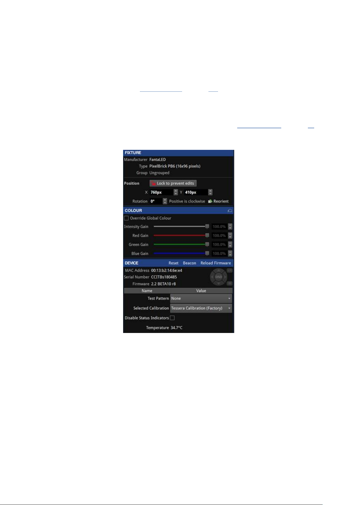
FIXTURE PROPERTIES
When selecting an online fixture from the canvas or from the online tab, the Fixture property editor appears.
The property editor sections are divided into Fixture, Colour and Device. See “Properties Area” on page 86 for
more information.
Figure7-1 . Fixtureproperty editor
FIXTURE
Fixture displays basic information about the selected fixture including manufacturer, fixture type and the
name of the group containing the fixture.
The second section of this editor displays the position and rotation of the fixture on the canvas. Modifications
can be made by typing or using the spin box arrows. Changes can be locked to avoid modifications. Reorient
rotates square fixture by 90 degrees clockwise, rectangular fixtures are re-oriented by 180 degrees.
COLOUR
Colour modifications can be enabled in the selected fixture independently from the Global Colour. When the
Override Global Colour box is ticked, colour modifications for the selected fixture are enabled and Global
Colour property editor values have no effect on the fixture.
46

PER-FIXTURE AND PER-GROUP COLOUR OVERRIDE
Figure7-2 . Global Colour Override options in Co lour property editor
Single fixtures or groups of fixtures can be made exempt from Global Colour control and assigned separate
values. This is useful to maintain one screen at a constant brightness when other fixtures are grouped into
separate screens on a processor.
To Override Global Colour, select the fixtures or groups to override and choose from options from the
property editor. Different options are made available depending on the users selection.
l If the selection is an ungrouped fixture or a combination of fixtures/groups, the options that can be
adjusted are:
l Intensity gain
l Red gain
l Green gain
l Blue gain
l If the selection is a group, the options that can be adjusted are:
l All the previous settings
l Brightness
l (Colour) Temperature
l Gamma
Note - Once a selection has been overridden on the Colour property editor, the Global
Colour controls have no effect on the selected fixtures until the checkbox for Override Global
Colour is unchecked.
47

DEVICE PROPERTIES
The device property editor shows information stored on the R2 receiver card.
FIXTURE QUICK ACCESS BUTTONS
In the title bar for the Device property editor, there are three quick access buttons:
l Reset: Reboots the fixture, video will stop displaying in the following devices connected in the same
string, as data is not passed through while the fixture is rebooting.
l Beacon: Activates the “Identify” test pattern, also called beacon, for the selected fixture. This can be
used to identify the panel from the back. While the panel is in beacon, the rear status indicator LED of
the panel blinks yellow.
Figure7-3 . A beaconed panel showing the Identify internal test pattern
l Reload firmware: Re-applies firmware for selected fixtures from the prioritised pack in the Fixture
Library. See “Fixture Library” on page 161 for more information.
DEVICE INFORMATION
The first section lists the MAC address, serial number and firmware version information of the R2 receiver card.
The OSD property editor can enable and control OSD shown on selected fixtures See “OSD” on page 50 for
more information.
TEST PATTERN
The Test Pattern drop-down menu allows the user to select a range of internal test patterns that are preprogrammed within the fixtures R2 receiver card. These patterns are viewable regardless of whether the fixture
is associated to the processor or not.
48

Figure7-4 . Internal Test Pattern drop- down menu
Although fixture models vary, most fixtures have a self-test button on the back of the fixture which can be
used to activate test patterns by holding on the button for 4 seconds. (Refer to fixture manufacturer
documentation for specific functionality).
SELECTED CALIBRATION
The Selected Calibration drop-down menu allows the user to select between the different calibration profiles
that are stored within the fixture's R2 receiver card.
Figure7-5 . Selected Calibration list
DISABLE STATUS INDICATOR
The status indicator of the root nodes can be disabled if necessary, by toggling the tick box.
SENSORS INFORMATION
Information from sensors such as temperature or humidity is displayed if available in the fixture.
49

OSD
OSD or On-Screen Display is supported on R2-based fixtures and offers the possibility to display information
on the fixture itself, the processor or the project.
Note - OSD is supported on rectangular fixtures with a minimum sizeof 64x64 pixels but no
larger than 1024 pixels in either dimension and up to 262,000 pixels (e.g. 512x512,
1024x256, etc.)
Note - RA-16 based fixtures are not supported
Figure 7-6. OSD controls
To access OSD, click on or select multiple fixtures to reveal the Fixture properties editor.
Click on the OSD button to activate, click again to deactivate. To navigate OSD, use the left and right arrows to
cycle through categories, and use the up and down arrows to cycle through pages within each category.
If viewing OSD from a distance, it can be useful to use enlarged fonts by pressing the size button next to
the OSD buttons. Fixtures must have a minimal of 128x128 pixels to use this feature.
To trigger OSD from using the rear self-test button on the back of a fixture, press and release the button three
times. OSD is only applicable to fixtures running firmware Tessera version 2.1 and above.
50

STUDIO MODE
Studio Mode reduces a fixture's maximum brightness while maintaining the PWM bit depth, thereby resulting
in improved image quality (with less banding) when running at low brightness. The maximum benefit is seen on
particularly bright fixtures, especially those running at relatively low PWM bit depth (14 bit or below). See
Studio mode on page 129 for more information.
For fixtures supporting this feature, Studio Mode can be enabled or disabled using the Studio Mode checkbox.
Below are somecomparison images showing the advantages of Dark Magic and Studio Mode.
Normal (no Dark Magic or Studio Mode)
Banding clearly visible at the low end of the gradient
Dark Magic (only)
Banding eliminated, some slight 'sparkle' visible
Studio Mode (only)
Banding less pronounced, but still visible
Dark Magic and Studio Mode
No banding and reduced sparkle
51

FIXTURE CONTEXT MENU
Right-click a fixture to open a context menu with a list of options. These options are grouped by type and some
options have keyboard shortcuts displayed on the right side column. If a fixture is un-associated, some options
areunavailable.
Figure7-7 . Fixturecontext menu options
Function Description
Copy Copy the selected fixtures
Place the copied fixtures in the canvas
Paste
Group
Ungroup
Remove from group
Reorient
Rotate selection Rotate the selected fixtures around the selection’s axis
Select string Select all the fixtures connected to the same string as the one selected
Send to back
Move to layer Move the selection to a layer
Disassociate Remove the association of the selected fixture
Correct association Fix the topology re-associating fixtures
Zoom to selection Fits the canvas zoom to display the selected fixture/fixtures
Snap active area to
selection
Delete Delete the selected fixture/fixtures
The rotation value is also added but other values such as the modifications in the
fixture Colour property editor (see “Fixture Properties in page 46”) are not copied
into the new fixture.
Make a group with the selected fixture/fixtures.
Grouping fixtures is necessary to create group presets or to control fixtures
properties via DMX or eDMX protocols.
Break the selected group/groups. Please note that ungrouping deletes the group
information (name, colour, etc) and movement records of the selected group in all
relevant presets.
Removes the selected fixture from a group without breaking the group.
To select one or several fixtures from a group, hold the Shift key while selecting the
fixture/fixtures.
Rotates square fixtures around their own axis by 90° and rectangular fixtures by
180°
Send to the back of the z-axis of the selected layer.
Please note that, above the z-axis order in a layer, the order of layers determine
which fixtures can be seen on top
Applies the scaler to fit the active area to the selected fixtures
52

ADDING FIXTURES TO A PROJECT
There are two main workflows for adding fixtures to a project.
l With fixtures connected to the processor. The project and fixture layout are created on a processor with
fixtures physically connected. In this caseuse Add Fixtures from Network
l Without fixtures connected to the processor (or in offline mode). If a fixture is not connected, select Add
Fixture from Library to access the fixture library containing all fixtures packs that are currently
installed on the processor.
See “Fixture Library” on page 161 for more information.
Users can use whichever workflow is most convenient for their project, including a combination of the two.
ADD FIXTURES FROM NETWORK
On the toolbar above the canvas space, the circular indicator on the Add Fixtures from Network button is
greyed out if fixtures are not detected or not connected to the processor. This feature is not accessible until
fixtures are physically connected and detected by the processor. Once detected, the indicator turns green.
After clicking Add Fixtures from Network, the toolbar displays detected fixtures and strings of fixtures grouped
by output ports. A string is a continuous daisy-chain of Tessera compatible fixtures.
Associating Fixtures
There are two ways to associate fixtures:
Quick association
When fixtures are connected to the processor, each string is assigned a unique numeric code. Entering the
code on the processor (using number keys or numpad) selects the corresponding string, the string then has the
first fixture attached to the cursor for placement on the canvas.
Figure 7-8. This figure shows a connected fixture wall output. The left image shows a numeric value
corresponding to the fixture when entering Associate Fixtures from Network. The right image shows
when a numerical value has been entered in the processor
Note - This feature is only supported by R2-based fixtures with at least 64x64 pixels.
Note- When the processor recognizes more than 9 strings attached, string numbers have
more than one digit, therefore strings must be entered with the samenumber of digits as the
number of the last string detected. e.g. 01 or 005.
Figure7-9 . Use the keyboard to enter the shown number on fixture string to add to canvas
53

Mouse selection association
Associating fixtures can also be done by selecting the port. All fixtures connected to each port are highlighted
with the same colour. For example, on a Tessera M2 LED processor, the fixtures on output 1 are always
highlighted in red. Similarly, when selecting a port on a root node, the ports is always highlighted in the same
colour such as port 1 is always red.
Figure7-1 0. Click on either port A or B to associat e to canvas
Figure7-1 1. Tessera SX40 with XD units, select one to associate to canvas
When associating by selecting ports for each string, the string is represented by a uniquecolour in the user
interface and physical fixtures. Fixtures illuminate corresponding to identified strings.
l The Tessera T1 LED processor only has a single output port so there is no port selection and only
displays available strings of fixtures.
l For the Tessera SX40 LED processor, the user needs to first select the trunk where the XD is connected
before continuing to ports compared to other processors.
l During fixture association, if the string contains multiple types of fixtures they are illustrated in the user
interface, and the current part of the string is highlighted.
Blind mode
Blind association is available to associate fixtures without highlighting. This feature can be toggled on/off in
Add Fixtures from Network view. To enter this mode with fixtures remaining in this state, hold the Alt button
when clicking on Add fixtures from network .
54

Rotation
Fixtures can be rotated before being placed on the canvas. Use the Rotation slider on the Draw Array property
editor or alternatively use Alt + mouse wheel to modify the rotation angle.
Figure 7-12. Draw array feature for rotating fixtures before placing
Array types
To place an array of fixtures, hold the left mouse button while placing the fixture. The array is direction
sensitive and topology changes depending on which direction the mouse is dragged.
Topology can be adjusted or re-assigned later from the Canvas view using the Topology tool.
Once an array is created, the Add Fixtures property editor is shown with the following options:
Group Fixtures
Groups the array that the user has created.
For Tessera M2 and T1 LED processors, there are 3 types of array layouts: Grid, Circle and Radial.
Note - Tessera SX40 or S4 LED processors only support grid arrays, circle/radial are not
available.
55

Grid arrays
The Grid Add Fixtures property editor contains options for the user to adjust position, change grid size, define
spacing between fixtures or rotate to a desired location.
Figure7-1 3. Grid fixture layout property editor
56

Circle arrays
The Circle Add Fixtures property editor contains options for the user to place fixtures in a circular array. The
radius, position, rotation and fixture count can be changed.
Figure7-1 4. Circle fixture layout property editor
Radial Arrays
Differs to the circle option by offering the option to place multiple fixtures in a circle, spanning outwards to
create a wider display. Unique options with Radial include adjusting the quantity of fixtures used per spoke,
the width and distance between fixtures.
Figure7-1 5. Radial fixture layout property editor
57

ADD FIXTURES FROM LIBRARY
It is possible to work offline and create a layout when fixtures are not connected either by using the Tessera
Offline Editor in Tessera Remote, or by using the local user interface. In each case the user will need to add
fixtures from the library, as no fixtures are connected so Add Fixtures From Network will be disabled.
Add Fixtures from Library displays the Fixture Library and Draw Array Fixture editor, allowing the user to draw
fixtures to your project’s utilizing the installed fixture packs available on the processor or on Tessera Remote.
Figure7-1 6. Fixture library with list of installed fixture firmware on the processor
The Search bar can be used to filter the list or find a specific fixture. To only display fixtures that are already
placed on the canvas, select Used in the top-right corner. Similarly, to only show connected fixtures click Online
to reducethe list to fixtures types that are connected to the processor.
Select a fixture from the list and click on the canvas to add the fixture.
ASSIGNING OR MODIFYING ONLINE FIXTURE TOPOLOGY
To associate a fixture already placed on the canvas:
Click the relevant fixture on the canvas.
1. If the fixtures on the canvas already have topology applied, the user is prompted to associate the rest of
the string using the highlighted red string. Press enter to associate the fixture to the string.
2. If only part of the string is required, hold the Shift key and select the last fixture to associate.
3. Alternatively, continue to associate fixtures individually by clicking each fixture on the canvas in turn.
If the user creates a new topology for panels which have already been associated, the old topology will be
discarded in favour of the new topology/association.
See “Understanding Topology and Association” on page 66 for more information.
58
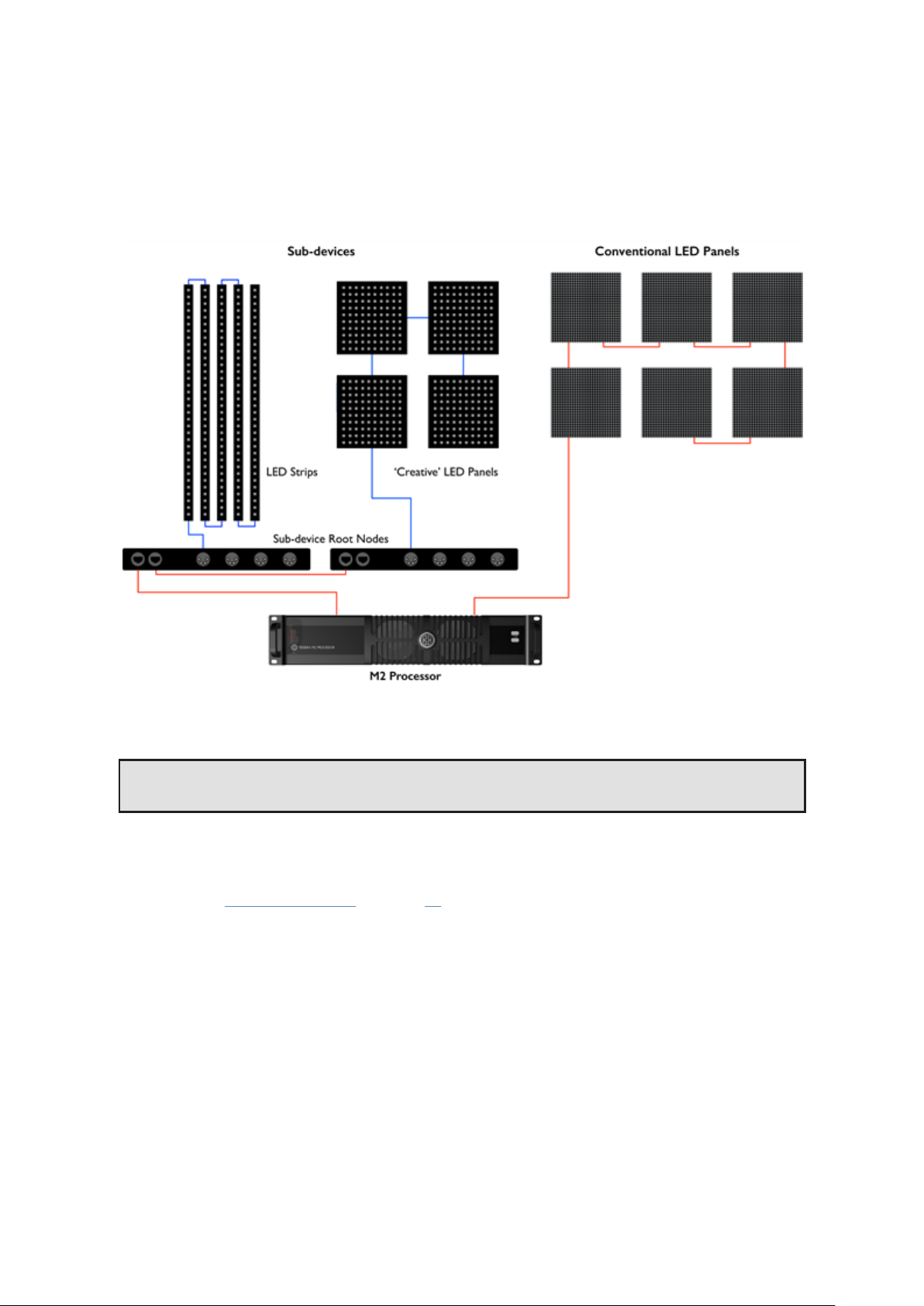
SUB-FIXTURES
Sub-fixtures do not have a Tessera interface and so cannot be connected directly to a Processor or XD output.
Instead multiple fixtures are connected to a single power/control box. These fixtures are represented in the
Tessera system as sub-fixtures. The power/control boxes are called root nodes.
Each root node contains a R2 receiver card, and like normal panel-type fixtures are connected to the rest of the
system over daisy-chained Gigabit Ethernet. Root nodes connect to sub-fixtures using a proprietary
data/power connection.
Figure7-1 7. Sub-fixtures being used with conventional LED panels
Note - Sub-fixtures are supported on Tessera SX40 version 2.3 and upwards.
SUB-FIXTURES PROPERTIES
The Fixture property editor is displayed when selecting an online root node or sub-fixture from the canvas or
the online view. See “Fixture Properties” on page 46 for more information.
59
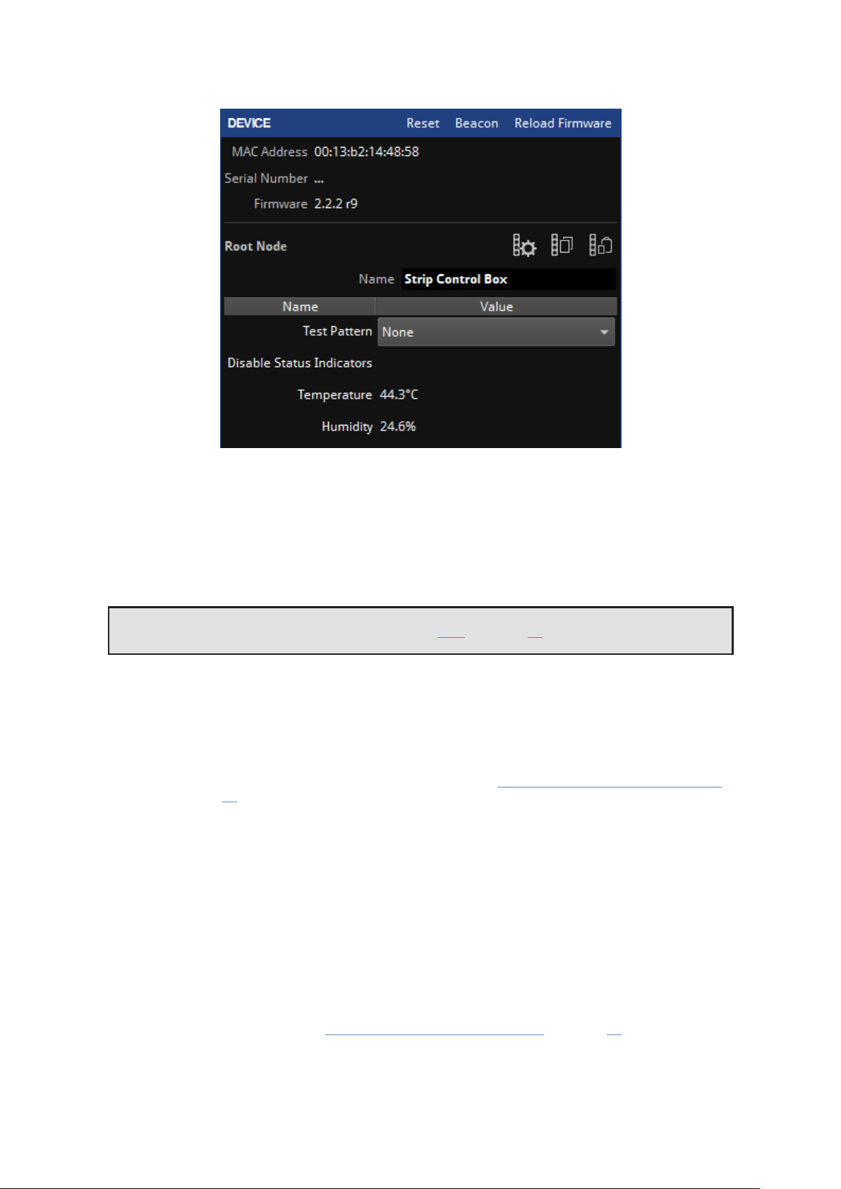
ROOT NODES PROPERTIES
Figure7-1 8. Device property editor
The device property editor shows the information of the R2 receiver card and the root node.
Device Information
The first section lists the MAC Address, serial number and firmware version information of the R2 receiver card.
Note - OSD is not available for sub-fixtures. See “OSD” on page 50 for more information
Configuration Buttons
Next to Root Node there are three buttons:
l Configure root node
Allows the user to specify sub-fixtures on each port. See the “Configuring the root nodes online, steps
5 and 6” on page 62 for more information.
l Copy root node configuration
Copy the configuration for the selected root node.
l Paste root node configuration
Paste the copied configuration for the selected root node.
Using Copy/Paste can make the workflow quicker when using larger amounts of root nodes. Several root
nodes can be selected, and the configuration pasted to all of them at the same time.
Test Pattern
The Test Pattern drop-down menu allows you to select a range of internal test patterns that are generated on
the fixtures R2 receiver card. The patterns can be displayed on all connected sub-fixtures whether they are
associated to the processor or not. See “Sub-fixture internal test patterns” on page 65 for more information.
Disable Status Indicator
The status indicator of the root nodes can be disabled by toggling the tick box.
60

Sensors Information
Information such as Temperature or Humidity is displayed if the root node has the appropriate sensors.
SUB-FIXTURES CONTEXT MENU
Right-click the root node to open a context menu with a list of options. Sub-fixture options are the same as
other fixture’s options. Root nodes have additional functions to “Configure” (only when the root node is
online) and “Add Sub-fixtures” options for root note configuration and the addition of sub-fixtures.
Figure7-1 9. Extra option for sub-fixtures in context menu
ASSOCIATING SUB-FIXTURES
Sub-fixtures may be individually positioned and rotated on the canvas, just like normal fixtures. Root nodes
arenot typically able to detect what types and quantities of sub-fixtures are connected to their outputs and
must be assigned by the processor. Root nodes can be added to the canvas using the Add Fixtures from
Library or Add Fixtures from Network tools.
ADDING SUB-FIXTURES ONLINE OR OFFLINE
Using Add Fixtures from Library or Add Fixtures from Network
1. Click Add Fixtures from Library or Add Fixtures from Network
2. Select the root node and place it on the canvas.
3. Press Enter to return to the Canvas view.
4. Right-click the root node and select Add Sub-fixtures.
5. The type of fixture can be selected from the Library list. Select the relevant sub-fixtures and add them to
the canvas.
6. Repeated presses of Tab or the Next Port button advances through the ports, before returning to
adding root nodes.
Figure7-2 0. Adding a sub-fixture to canvas
7. Repeat steps 5 and 6 until all fixtures are placed.
8. Press Enter or Escape to confirm the association
9. If the configuration of the root nodes does not match the fixtures on the canvas, a notification is
displayed. Click the button to confirm.
61

Figure7-2 1. Notification to configure root nodes not matching fixture topology
CONFIGURING THE ROOT NODES ONLINE
Using Add Fixtures from Network . The root nodes need to be connected to the processor and online.
1. Click Add Fixtures from Library or Add Fixtures from Network
2. Select the root node and place it on the canvas.
3. Press Enter to return to Canvas view.
4. Right-click the root node and select Configure. A new window opens with the root node configuration
options.
Figure7-2 2. Strip cont rol box configuration menu
5. The control box stores the last configuration from previous projects. To delete all associated sub-
fixtures click Clear all ports or to delete individual sub-fixtures, select and press the delete button.
6. Select the port, sub-fixture type and the number of sub-fixtures then click Add devices. This may take a
couple of seconds for the root node to configure.
Once configured, sub-fixtures can be added. If the topology differs from the root node configuration, root
nodes can be reconfigured by pressing the Configure Root Nodes button in the error message.
Figure7-2 3. Notification to configure root nodes not matching fixture topology
62

OFFLINE
Using Add Fixtures from Library
1. Click Add Fixtures from Library.
2. Select the root nodes and place on the canvas. The search bar can be used to filter fixtures.
Figure 7-24. Adding a Root node to canvas
3. Press Tab to start associating sub-fixtures. Repeated presses of Tab or the Next Port button advances
through the ports.
4. The type of fixture can be selected from the Library menu. Select the sub-fixtures and add them to the
canvas.
Figure 7-25. Adding a sub-fixture to canvas
5. Repeat steps 3 and 4 until all your fixtures are placed.
6. Press Enter or Escape to confirm the association.
Once fixtures are connected to the processor, the root nodes can be associated. Strings of root nodes appear
the same as strings of normal fixtures in the Add Fixtures From Network tool. See "Adding Fixtures to a
Project" on page 53 for more information.
When a root node is associated, its outputs is automatically reconfigured with the correct types of sub-fixtures
drawn in the topology, and sub-fixtures are automatically associated.
ONLINE
Using Add Fixtures from Network
This option restricts the addition of sub-fixtures to the configuration of the root node. The processor does not
receive information regarding the number of connected sub-fixtures.
1. Click Add Fixtures from Network
2. Select the port for connected fixtures.
3. Select the root node and associate it to the canvas. This step is not necessary but is useful if the root
node configuration needs to be changed.
4. Select the sub-fixtures.
5. Select the root node where the sub-fixtures are connected.
63

6. Select the port connected to the root node for association.
7. Draw the sub-fixtures of the selected port on the canvas and continue to other connected ports.
8. Press escape to got to the previous menu or enter to finish association and return to Canvas view.
If the configuration is correct, all sub-fixtures are now ready for use.
Note - Root nodes are limited in terms of the types, quantities and combinations of subfixtures that can be connected to their outputs. These constraints are enforced when adding
sub-fixtures to root nodes. See the fixture manufacturer's documentation for more
information.
The Edit Topology tool can be used to modify the connections between root nodes and/or sub-fixtures after
they have been added.
If fixtures are placed on the canvas and physically connected to the processor, use the Add Fixtures from
Network tool to associate strings of root nodes in the same way as strings of normal fixtures. When a root
node is associated, its outputs are automatically assigned with the correct types of sub-fixtures.
It is not normally necessary to individually associate sub-fixtures. If a sub-fixture doesn’t appear associated,
the root node can be disassociated by right-clicking and selecting Disassociate.
Figure7-2 6. Context menu to disas sociate a f ixture
To re-associate the root-node, right click and select Correct Association to automatically correct the topology
for the root node and all connected sub-fixtures.
64

Figure7-2 7. Context menu to correct association once a f ixture on canvas is discovered
SUB-FIXTURE INTERNAL TEST PATTERNS
Test patterns can be enabled on sub-fixtures from the fixture properties editor. Different patterns can be
enabled on each sub-fixture. If test patterns are enabled on one sub-fixture, all other sub-fixtures on that root
node will cease to display live video.
A small subset of internal test patterns can also be enabled on root nodes. All sub-fixtures connected to the
root node, including one’s not currently configured/associated to sub-fixtures areilluminated.
65

UNDERSTANDING TOPOLOGY AND ASSOCIATION
Tessera processors can detect the topology of connected fixtures. Topology is the order which fixtures are
connected, which port on the processor they are connected to and if fixtures are broken into strings by
switches. The topology tools are used to help users associate physical fixtures with fixtures on the canvas.
Fixtures are identified by a unique MAC address. When a physical fixture is associated in the project, the MAC
address is recorded, and association persists until the user makes changes.
If the real-world topology is changed after fixtures are associated, For example; a video wall is re-cabled, the
fixture association is not automatically re-configured by the processor. Turn on Show Topology Errors in
Canvas Properties (right-click on canvas) or in the View dropdown menu to highlight in red any changes found
on the canvas.
Figure7-2 8. Example of incorrect topology, notice the arrows on the far left and right are highlighted in red
SWAPPING FIXTURES AND CORRECTING ASSOCIATION
Each fixture connected to a Tessera processor is recognised as a unique fixture. Each unique fixture is
associated with a position on the canvas. If a fixture goes offlineor is removed, the fixture remains on the
canvas but is now disassociated. The status indicator on the Add fixtures from network button only turns grey
when fixtures are offline.
In instances where a fixture is swapped out from the string, the processor will detect a disappearance and a
new fixture will appear in the same position. The processor will detect a swap-out has taken place and will offer
the user the option to perform Correct Association.
TO PERFORM A SWAP-OUT OF ONE FIXTURE:
1. Disconnect and remove the fixture.
2. Insert and connect a new fixture into the same position of the string. The processor prompts the user
with the following message:
Figure7-2 9. The correct association dialog box
3. This message is available for 10 seconds. After this message expires, the Correct Association option can
be found by right-clicking on the icon of the affected fixture or by selecting Correct Association from the
Edit dropdown menu or edit topology toolbar .
66

CHANGING PHYSICAL TOPOLOGY
If the fixtures’ topology is modified, for example to balance the ports load, the fixtures are automatically reassociated.
Example: The fixtures in a wall are associated to the processor in a topology using ports 1 and 2 as shown
below:
Figure7-3 0. Fixtures associated to the process or using ports 1 and 2
Due to the port capacity restrictions, the topology of some fixtures need to be changed from port 1 to port 2
to balance the load on ports.
67

Figure 7-31. Fixtures with topology changed to balance laod on ports
The processor automatically recognizes the fixtures MAC addresses and re-associates this fixture in the project.
To see the topology errors, enable Show Topology Errors in the canvas view. The fixtures automatically begin
functioning at this stage.
The processor may prompt the following message:
Figure7-3 2. The correct association dialog box
Confirm by pressing the Correct Association button .
The Correct Association option can be also done by selecting Correct Association from the Edit dropdown
menu or in the Edit topology toolbar menu .
Pressing the correct association button repairs the canvas topology.
CHANGING CANVAS TOPOLOGY
The topology can be manually changed using the topology toolbar that appears when pressing the Edit
Topology button.
Figure7-3 3. Topology viewoptions
As an example, if the fixtures were first cabled in a continuous string from left to right and from bottom to top
as viewed from the front of the screen.
68

Figure7-3 4. First topology
The second time the fixtures are connected, the cabling topology is changed, as shown below.
Figure7-3 5. Second topology
69

To correct the screen, use the following steps:
1. On the canvas select all fixtures with the incorrect topology. Right-click the fixtures and select
Disassociate.
2. Click Edit Topology to view the Topology toolbar and select the string of fixtures requiring correction by
double-clicking on the dot in the centre of a fixture. The whole string is coloured red.
Figure7-3 6. The topology is drawn on all fixtures in the string
3. The strike in the Remove Link button changes from grey to red once a string is selected, indicating that it
can now be used. Click on it to remove the topology.
4. Hover the mouse over the centre spot of the fixture which is to be at the start of the string. Click and
drag the pointer to the centre spot of the second fixture on the string. A dotted red line is drawn which
turns solid as the line becomes pinned to the centre spot of the next fixture in the string.
5. Repeat the process until the string is complete.
Figure7-3 7. Re-applying the string
6.
The topology direction can be reversed by clicking Reverse topology when a string is highlighted.
70

Figure7-3 8. Completed topology string
7. Once corrections are complete, return to the main project view by pressing Esc or clicking on the arrow
located at the top left of the interface . The processor detects a new topology which doesn’t match the
current association and displays the Correct Association message for 10 seconds.
Figure7-3 9. The incorrect topology notification
8. Click the Correct Association button to finish the process. The fixture icons display a green indicator
when associated to the canvas. Source content can be displayed on associated fixtures.
Figure7-4 0. The fixtures areonline and associated.
Alternatively, the string can be associated using Add Fixtures from Network. See “Associating fixtures” on page
53 for more information.
71

FIXTURE LAYOUT
SELECTING INDIVIDUAL FIXTURES
Click to select a fixture.The fixture will turn blue and the Fixture property editor will be displayed on the right
sideof the user interface. See “Fixture Properties” on page 46 for more information. Right-click on a fixture to
display a context menu. See “Fixture Context Menu” on page 52 for more information.
SELECTING MULTIPLE FIXTURES
There are various methods to select multiple fixtures:
l Ctrl + left-click on fixtures to individually select them.
l Hold the left mouse button and drag to create a selection box around the fixtures, release button to
finish selecting. For more information about selection modes, see “Selection Mode” on page 166 for
more information.
l To select all fixtures on the canvas, use Ctrl + A, or ⌘ + A on Mac OSX.
GROUPING FIXTURES
A selection of fixtures can be combined into a group. When changes are madewith the group selected, such as
moving or adjusting colour, the fixtures contained within the group always change together. This feature saves
time by not having to configure fixtures separately and improves accuracy by moving a wall of fixtures making
sure that the relative position of the fixtures don’t change.
To set a group, select the required fixtures, right-click to show the context menu and choose Group, the same
method is used to ungroup fixtures. Use Ctrl+G to group fixtures or Ctrl+Shift+G to ungroup fixtures.
To select one or several fixtures from a group, hold the Shift key while selecting the fixture/fixtures. These
fixtures remain in the group while being modified, without breaking the group.
Note - If a group is broken by ungrouping or removing fixtures, all relevant presets where the
group has a recorded position will also be updated/deleted accordingly. Thefollowing
warning is displayed: “Any colour overrides associated with that group will be lost”.
GROUP PROPERTIES
The Group property editor appears when a group is selected. It is composed of Group and Colour.
72
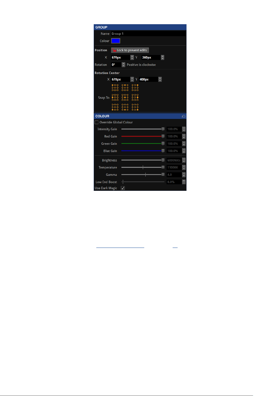
Figure7-4 1. Group properties
Group
The group property editor is divided in three sections.
Group info
l Name: Change the name of the group.
l To see the name in the canvas, activate Show Group Names in the View dropdown menu or in the
Canvas context menu. See “Canvas Context Menu” on the page 80 for more information.
l Colour: Click in the colour box to select a different colour from the palette.
Position
The second section of this property editor displays the position and rotation of the fixture in the canvas.
Changes can be locked to avoid modifications. Modifications can be made by typing or using the spin box
arrows. The Reorient button rotates the fixture by 90 degrees clockwise for square fixtures, or 180 degrees for
rectangular fixtures.
Rotation centre
The rotation centre of the group can be modified. The canvas coordinates for the centre can be typed or
selected in the spin boxes. Alternatively, choose one of the Snap To options to place it in the predefined
positions of the group.
73

Colour
Colour modifications can be enabled in the selected fixture independently from the Global Colour. When the
Override Global Colour box is ticked, colour modifications for the selected fixture are enabled and Global
Colour property editor values do not have an effect on the fixture.
GROUP CONTEXT MENU
Right-click in a group to open a context menu with a list of options. Group options are a small selection of the
Fixture options. The Select Grouped Fixtures option eases the selection of the fixtures contained in the group
instead of the group itself.
Figure7-4 2. Context menu when selecting a group, including an option to ungroup
Select one or several fixtures from a group by pressing the Shift key while selecting the fixture/fixtures. These
fixtures remain in the group while being modified, without ungrouping.
MOVING FIXTURES
Fixtures can be moved anywhere on the Canvas, either within or outside of the Active Area by selecting the
fixture and dragging with a mouse or pressing arrow keys on the keyboard. Pressing the arrow keys will move
the fixture by grid-space increments. The grid space increment size can be modified in the Canvas properties
dropdown menu. See “Canvas Properties” on page 78 for more information.
74
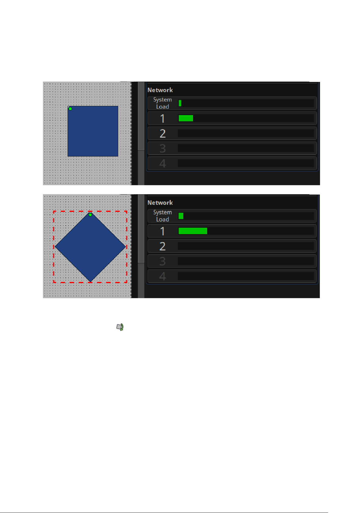
ROTATING FIXTURES
Fixtures can be rotated by 90-degree increments on all processors, however Tessera M2 and T1 LED processors
support free rotation, allowing rotation to any degree at a cost of doubling the bandwidth required to drive the
fixtures.
Figure7-4 3. Network load is increased when rotating fixtures by 9 0 degrees
Fixtures can be individually rotated around their top-left corners by first selecting the fixture, then either click
the rotation icon in the toolbar or right-clicking and selecting Rotate Selection. An anchor spot with a handle
appears over the fixtures. Both can be dragged to a desired position to change the rotation axis and the
rotation angle, respectively.
75

Figure7-4 4. Manually rotate a f ixture using the anchor handle
Alternatively press Ctrl+Shift+R or select from the Edit property editor to enter rotation mode.
Fixtures can also be rotated during association by pressing the Alt key and using the mouse wheel to change
the rotation angle.
Note - The Tessera S4 and SX40 LED processors can only rotate in 90-degree increments.
For further information on how rotating fixtures affects network load see "Other factors affecting output
capacity" on page 27.
76

CHAPTER 8 - MAIN PROJECT SCREEN
When creating a new project, the Main Project Screen opens with multipleview modes:
l Canvas view: Allows layout editing and visualization of fixture position on the selected canvas,
topologies, video source and access to the tools for image adjustment in the LED devices, and
troubleshooting.
l Topology view (Tessera SX40 only): Provides a representation of the connections between the
processors, XD units and fixtures.
l Online view: Provides a list of the fixtures connected and information received by the processor
including ports, errors etc.
CANVAS VIEW
The Canvas View gives access to tools for content placement on fixtures, video modifications and adjustment.
Figure8-1 . Tessera Processor showing Canvas View in detail
77

CANVAS PROPERTIES
The canvas properties editor can be accessed by selecting Properties in the canvas properties toolbar, on the
top-right of the canvas.
Figure8-2 . Canvas properties
Size
The canvas size can be freely modified however the input source must fit within the width and height
dimensions. Depending on the selected resolution, some limitations might apply. See “Canvas Resolutions” on
page 42 for more information.
Pixel Pitch
This option is for Tessera M2 and T1 processors and only appears when fixtures with two different pixel
pitches are drawn in the canvas. Clicking the check-box alternates between 1:1 and interpolated modes. See
“Mapping Options” on page 43 for more information.
Units
Select between millimetres, inches or pixels for the background modifications.
BACKGROUND
Show
Toggle to enable or disable the background view.
File
Click Browse to navigate to a image file from the USB drive or computer (when in Remote mode) to display in
the background on the canvas. GIF, JPG or PNGfiles are compatible.
By default, the image aligns to the top-left of the canvas.
Video snapshot will capture a image of the selected input source and apply it to the canvas background.
Clear
Deletes the assigned background.
78

Scale
If the image size differs to the canvas size or to the desired size, the sizecan be modified by selecting a pixel
ratio. When the selected units are pixels, a 1px value will show the real size of the image, values lower than 1px
reduces the image size while values above increase its size.
Press edit to click and drag a line on the background image and specify the final length that it should take in the
canvas. The limit of this value is 1000px.
X/Y
Adjust the position of the top-left corner on the background image.
GRID
Colour
If desired, the grid dots colour can be modified. This can be useful when using a background with an identical
colour, to be able to differentiate the grid dots.
Spacing
Define the grid space in pixels. This value also modifies the number of pixels that a fixture is moved when using
the keyboard arrows to move it around the canvas.
CANVAS EDITS ENABLED
Enables or disables modifiying the active area size or position of the canvas. This can be done by clicking the
edges of the canvas and dragging to resize it.
See “Active Area” on page 112 for more information.
79

CANVAS CONTEXT MENU
Right-click an unused area of the canvas to open a context menu with a list of options to customize the
appearance and usability of the canvas.
Figure8-3 . Context menu when right-clicking unused area on canvas
Function Description
Paste Paste the previously copied fixture to this place on the canvas.
Zoom To Fit
Zoom to selection
Zoom 1:1 Adjust the zoom to show the canvas with a 1 to 1 resolution of the display.
Toggle Navigator Show or hide the navigator window.
Show Root Nodes Root nodes can be shown or hidden.
Show Topology Fixture’s topology can be shown or hidden.
Show Group Names Group Names can be shown or hidden.
Show Grid Grid dots can be shown or hidden at convenience.
Snap to Grid
Snap to Fixtures
Adjust the zoom and view position to display the complete canvas in the centre of
the screen.
Adjust the zoom and view position to fit the selected fixtures in the centre of the
screen
Pull fixtures into perfect alignment with the grid. Is enabled by default, helping to
align or space fixtures evenly on the canvas
Pull fixtures into perfect alignment with other fixtures. Is enabled by default to align
fixtures evenly on the canvas avoiding overlapping or small gaps.
80

CANVAS TOOLBAR
The Main Toolbar offers a selection of tools to draw fixtures on the canvas and select zoom and view positions.
Figure8-4 . Canvas toolbar features
Icon Icon Description Description
Undo/Redoarrows
Add Fixtures from Library
Add Fixtures from
Network
Edit Topology
Free Rotation of Selected
Fixtures
Undo and redo the last action performed. The shortcut commands for
Undo are Ctrl+Z (⌘ +Z) and Redo with Ctrl+Shift+Z or Ctrl+Y
Access to a menu with all the fixtures included in the fixture packs
currently added to the processor. Once connected, these fixtures
require associating. See “Adding Fixtures to a Project” on page 53 for
more information.
This button does not appear in the offline mode and is greyed out if
there are no fixtures connected to the processor. Gives access to a
menu for associating physically connected fixtures. See “Adding
Fixtures to a Project” on page 53 for more information.
Modify and correct the topology connections between fixtures already
added.
After clicking, an anchor spot with a handle appears over the fixtures.
Both can be dragged to a desired position to change the rotation axis
and the rotation angle, respectively. See “Rotating Fixtures” on page 75
for more information.
Zoom In and Zoom Out To adjust the view of canvas to appear larger or smaller.
Zoom To Fit
Zoom To Selection
Zoom 1:1
Toggle Navigator Show or hide the navigator window.
Adjust the zoom and view position to display the full size of the canvas
in the centre of the screen.
Adjust the zoom and view position to fit the selected fixtures in the
centre of the screen.
Adjust the zoom to show the canvas with a 1 to 1 resolution of the
display
81

CANVAS EDIT VIEWS
EDIT MODE
Edit Mode views allow fixtures to be positioned on the canvas.
Edit Mode:
Keyboard Shortcut: F1
Edit Mode is the default mode for the canvas and allows fixture positioning. In Edit mode the fixtures are
displayed as viewed from the front.
Rear Edit Mode:
Keyboard Shortcut: F2
Fixtures are commonly cabled from behind and Rear Edit allows fixtures on the canvas to be horizontally
flipped, as if viewed from behind. This is particularly helpful when you are associating fixtures or
troubleshooting from behind the fixtures.
82

VIDEO ON CANVAS MODE
The Video on Canvas Mode view displays the currently selected video input onto the Canvas, including
Viewport and Active Area settings. This mode shows how input content is displayed on fixtures in real-time.
Note - Video on Canvas mode is not available on Tessera S4 processor or accessible using
Tessera Remote. Fixtures cannot be moved on the canvas whilst in Video on Canvas Modes.
Fixture Only Mode:
Keyboard Shortcut: F3
Fixture only mode displays the currently selected video input as it is being displayed on the fixtures.
83

Video And Fixture Mode:
Keyboard Shortcut: F4
Video and Fixture Mode displays the current video input on both the fixtures and the canvas. The video within
the Active Area that is not being displayed on the fixtures is shown greyed out as shown in the picturebelow.
Video Only Mode
Keyboard Shortcut: F5
Video Only Mode displays the current video input within the Active Area on the canvas without displaying the
fixtures. This mode is useful to preview the input source size and position in the canvas.
84

HEAT MAP
Keyboard Shortcut F6
Selecting 'Heat Map' from the canvas display mode button (or pressing F6) displays fixtures on the canvas
coloured based on the temperature reported by internal sensors.
The fixtures display a colour representing the temperature. Temperatures ranging from the coolest fixtures
(black) to the hottest fixtures (white). Fixtures that are offline or that haven't reported a temperature are
displayed with a grey hatched pattern.
LAYERS
Figure 8-5. The Layers property editor
Layers are an easy way of managing overlapping fixtures.
85

Fixtures can be assigned to layers which have a Z-order. Z-order refers to the front to back ordering.
Layers are particularly useful when two groups of fixtures are superimposed on the canvas, so that the content
can be easily duplicated on two sets of fixtures, such as when using two screens showing the same content on
either side of the stage. Layers make it easier and more accurate to select between the two groups of fixtures
when making OSCA or other fixture-based adjustments.
Toggling the tick box of a layer shows or hides the layer without affecting the output. Clicking and dragging a
highlighted layer up or down allows the Z-order of the layer to be adjusted.
Layers can be assigned or adjusted at any point within the Canvas view. On the right-side of the toolbar, there
is a drop-down menu containing layers created for the current project. This menu contains options to add
layers , remove layers , drag to prioritise layers and toggle visibility of layers.
Rename a layer by double-clicking the layer name in the layers dropdown menu.
To assign fixtures to layers, select the fixture and right-click. Under Move to Layer, select the layer to use.
PROPERTIES AREA
When working in canvas mode, the Properties area is located on the right side of the screen. It can be shown or
hidden by clicking the double-arrow button placed next to the canvas properties toolbar.
Fixture information, canvas and/or pipeline tiles is displayed in this area.
Figure8-6 . The properties area is on the right side of the canvas
When selecting pipeline tiles, a fixture, a group or a combination of fixtures and/or groups, a property editor
with information and properties is shown in the Properties area.
WORKING WITH PROPERTY EDITORS
Activate A Feature
Pipeline tile functions can be activated and deactivated by double-clicking on a pipeline tile or Enable button,
next to the name.
86

Stack Property Editor Widgets
A selection of property editor widgets can be arranged to be displayed simultaneously. Press and hold the
CTRL button while clicking in the desired Pipeline tiles to see how the Property editors get added on the
Properties area.
A fixture or group property editor can also be selected.
Note - The property editor for a selection of groups/fixtures only displays common settings.
The positions, rotation and colour modifications are applied to all selected objects.
Pin Property Editor Widgets To Properties Area
To pin and fix a property editor widget to the properties area so it does not disappear when a different object
is selected, press the pin button located on the right side of the editor title bar.
The editor can still be closed by pressing the close button located on the right side of the editor title bar.
Close Property Editor Widgets
When a new object such as a pipeline tile, fixture or group is selected, a property editor opens, closing all other
Property editors, except those pinned.
Property editors can also be closed by using the close button located on the right side of the editor title bar.
Reset All Values To Default
To reset all the values contained in the Properties editor to default, press the reset button located on the
right side of the editor title bar.
Re-arrange Property Editors
The order of the property editors can be changed by clicking and dragging the property editor title bar and
placing it in a different position.
87

PIPELINE
The pipeline represents the signal flow through the processor. The pipeline is composed of tiles arranged in
groups.
Working With Pipeline Tiles
Activating Settings
A white bar on the pipeline tile appears when settings are active. Double-click the pipeline tile to switch settings
on or off.
Unselected Pipeline tile is disabled
Single click Pipeline tile disabled, property editor shown
Double click
Double click Pipeline tile enabled, property editor shown
Pipeline tile enabled, property editor not shown unless pinned to property
area
Open The Property Editor
Pipeline tile properties can be viewed and adjusted by single clicking on a tile to prompt the property editor to
appear.
Note - The selected tiles settings are only activated by double-clicking on the Pipeline tile or
toggling the Enable button in the left side of the property editor title bar.
When a property editor is open, the pipeline tile is highlighted in blue.
88

PRESETS
At the bottom of the Main Project Screen, presets can be set to store settings on the processor. Presets can be
made to affect all fixtures, a selection of fixtures or groups. The video source modifications affects all fixtures
on the canvas.
Available options to save into presets include:
l Affecting only selected groups or fixtures
l Fixture or group colour (with override global colour enabled)
l Group position on the canvas (Only affects groups. The group must be selected during preset
recording)
l Affecting all fixtures:
l Video source selection
l Video source properties
l Global Colour
l Geometry information (Viewport and Active Area)
Figure8-7 . Main Project Screen with record buttons highlighted
Presets can be used to set different colour and brightness settings to compensate for changes from day to
night or cloudy versus sunny conditions.
89

USING MASKING
Figure8-8 . Preset Recording view
Masking is useful for security when changing fixture position without altering colour information or to change
the input source without affecting the global colour.
When a preset is stored, three icons are displayed. The icons represent information that will be stored within
the preset. Colour, position, and video settings can be selected or deselected to include or exclude them from
the preset.
RECORDING PRESETS
1. Group the required fixtures and allocate a position on the canvas for the preset to record.
Note - A group can consist of a single fixture.
2. Set the parameters of colour, position or video to store as a preset.
3.
Click the red preset record button .
4.
Select or deselect the masking controls for colour , position or video input .
5. The tiles of the available fixture groups appear with striped diagonal lines.
90

6. Only selected groups are stored into a Position preset. Once selected, the diagonal lines on the groups
change to solid colour.
If no group is selected, the following warning is shown.
7. Click an empty preset tile to store the new preset.
8. When double-clicking a preset, the preset recalls settings for associated groups.
EDITING PRESETS
To change any parameters of a stored preset, the preset must be re-recorded. Double-click the stored preset
tile, make changes and click the Preset Record button to save.
Right-click on a stored preset tile to rename or delete it.
PRESET PROPERTIES
Click once in a preset to open its property editor.
Name Option to rename the preset tile
Fade Time Select the cross-fade time
Fade Through Black Activate to go to black before crossfading to the new source input
Cross-fading This feature is only available on the Tessera M2 LED processor
Switching inputs can be achieved by creating a Video preset for each input.
91
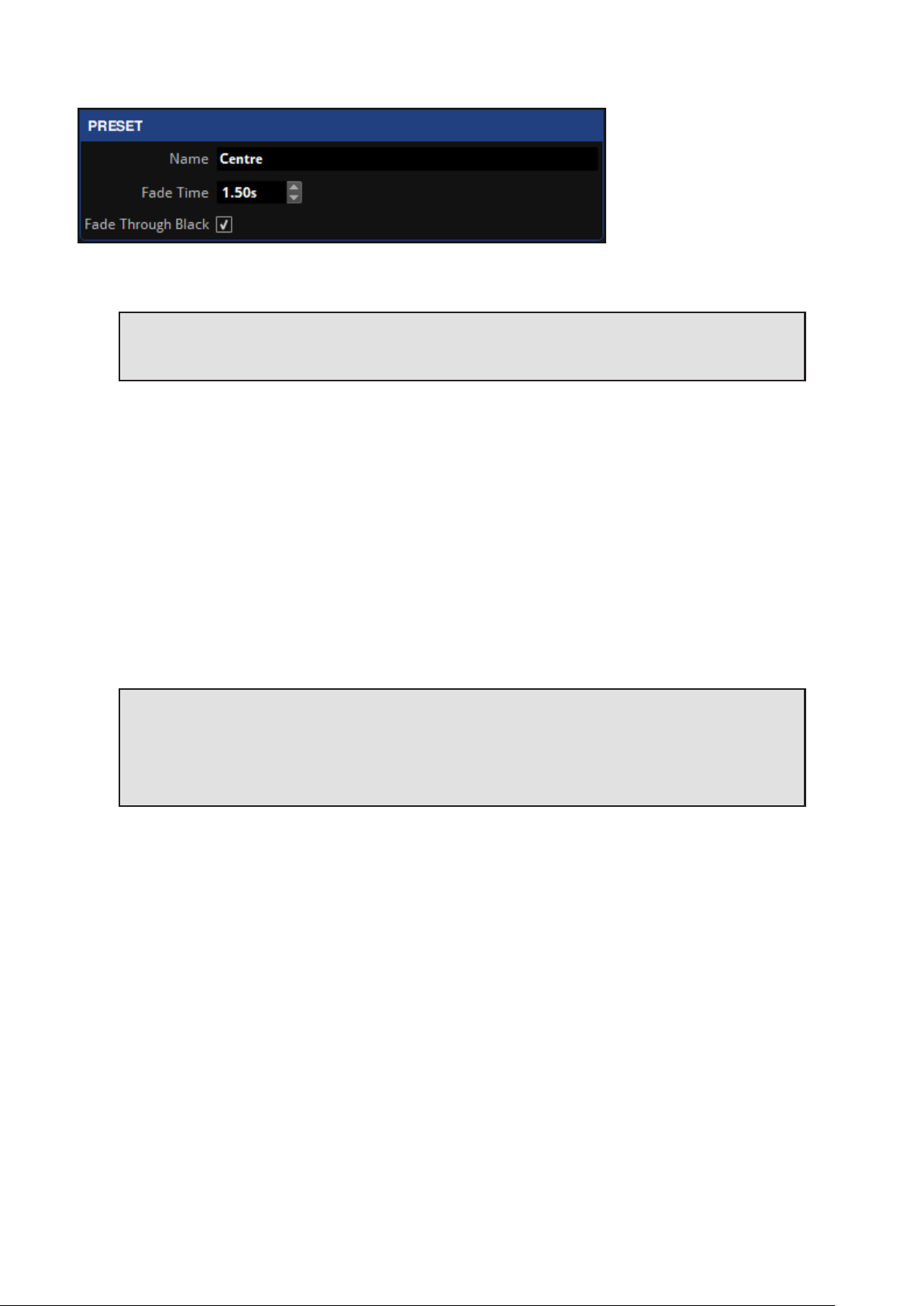
Note - Other values like Colour and Position are not affected by the fade times and are
committed as soon as the preset is activated. Crossfade only affects the source selection.
Crossfading between inputs can be achieved by storing the different inputs as presets with a fade time. To
store presets to crossfade from one input to another follow these steps:
1. Select the first input for the preset (all tiles are changed to this input).
2. Click the Preset Record button .
3. Select a slot for the preset.
4. Activate a different input by double-clicking on a source pipeline tile (video thumbnail).
5. Repeat steps 2 and 3 to create a new preset for this input.
6. Click on each preset to view properties or set a fade time for the preset.
The presets are ready to crossfade between the inputs.
Note - Note - Tessera M2 LED processor has two input pipelines, each can process up to a
1920x1080 raster at 60Hz. When an input is selected, the input is mapped to the currently
unused pipeline then fed into the mixer and scaler functions of the processor. Once any
crossfading is complete, the other pipeline is then freed for the next selected input when
selected.
92

LOG
Information about the processes and errors that occur within the processor can be viewed by clicking on Log.
This information can be stored in a USB drive or on the computer using the button Save the Log .
93

MOVING AROUND THE CANVAS
Move Controls
Vertical scrollbar
Arrow keys
Page up/down keys
Up, down, left and right
Mouse wheel
Horizontal scrollbar
Arrow keys
Shift + mouse wheel
Use in the main toolbar
Ctrl + mouse wheel
Zoom in and out
Ctrl + + to zoom in, Ctrl +- to zoom out
Zoom to fit, Zoom 1:1 or Zoom to selection options
Drag the canvas Hold the space bar and left-click + drag with the mouse
Modify the scaler options
Modify the active area
On the edges of the active area, click and drag as the cursor becomes a doubleheaded arrow
Modify the scaler options
Move the active area
On the top-left of the active area, click and drag as the hand cursor appears
NAVIGATOR
The Navigator provides a simple way of moving around the canvas and adjusting zoom levels. A mini preview
of the canvas is displayed, with a red box showing the current visible canvas area. Dragging the box moves the
canvas view, and a slider is available for zooming in and out.
Open or close the Navigator window by:
l
Clicking the button from the toolbar
l Clicking the button intersecting the canvas Scrollbars.
l Select Toggle Navigator from the canvas context menu.
l Select Toggle Navigator from the View menu.
l Press Ctrl+Shift+N (or ⌘ +Shift+N on Mac)
94

PROJECT DATA EXPORT
Tessera software has three types of files that can be exported: Canvas image, device layout and discovered
devices.
EXPORT CANVAS IMAGE
To export an image, navigate to Tools and select Export Canvas Image. Several options are displayed for the
user to choose and control how exported images are rendered. After selecting export options, the user is
prompted to select an export location, either on the local file system when using Tessera Remote or on a USB
storage device attached to the processor when using the local user interface.
The exported image in PNG format is a pixel-accurate representation of the canvas and has the same
dimensions as the canvas.
Note - If using the exported image for content creation, we recommend using the image as a
guide only. This avoids artefacts due to aliasing at the edges of small and rotated fixtures.
EXPORT DEVICE LAYOUT
To export the device layout data as a CSV file, navigate to the Tools dropdown menu and select Export Device
Layout. The CSV file contains a row for every fixture on the canvas. To choose the columns, select fields from
the left list and press the right arrow to move them to the right list. To individually select multiple fields, Hold
Ctrl(⌘ for Mac) and click each field.
After choosing export options, select a storage location, either on the local file system when using Tessera
Remote or on a USB storage device attached to the processor when using the local user interface.
Data is exported in Comma-Separated Values (CSV) format, which can be opened with spreadsheet
applications such as Microsoft Excel, or a simple text editor.
EXPORT DISCOVERED DEVICES
Export discovered devices, exports information identical to the Online view therefore selected filter options,
column hiding, and sorting also applies to the exported data. By default this includes:
l Port
l Type
l Serial Number
l Firmware
l Progress
l Port 1 Status
l Port 2 Status
l Temperature
l Orientation
l Status
l Authentication
Navigate to the Tools dropdown menu and select Export Discovered Devices or from Online view and selecting
Export Discovered Panels.
Data is exported in Comma-Separated Values (CSV) format.The exported data can be opened and manipulated
in spreadsheet applications such as Microsoft Excel, or in simple text editors.
95

ONLINE VIEW
The Online Fixtures view provides comprehensive information about all fixtures currently detected by the
processors output ports.
EXPORTING ONLINE FIXTURE DATA
To export information regarding connected fixtures, navigate to either the Tools drop-down menu or the
Online view and click the Export Discovered Devices button.For more information see: Project Data Export on
page 95
NETWORK ERROR MONITORING
To help track down faulty cables and connectors in a large system, the Online tab shows an error counter for
each connected fixture. Error counters start at zero when the fixture is powered-up and may be manually reset
to zero by right-clicking.
Figure8-9 . Resetting Network Errors
Fixtures must be running V1.5.0 or later firmware and must be associated (i.e. added to the canvas) for the
processor to read the error counts.
Errors do not propagate through the system, which helps to quickly locate a faulty cable. For example:
Figure8-1 0. Using Network Errors to locate a faulty cable
The error counter values are not reset by events such as the link going up or down, or the fixture being
disconnected and reconnected. This is useful for long-term tests as an unexpected disconnection does not
increase the error count.
A small number of receive errors can be expected when hot-plugging data cables or power cycling fixtures or
processor. This is normal behaviour and does not indicate a fault. At other times, any error count increase
indicates a potential fault that should be investigated.
96

Error counters update every couple of seconds, which helps to correlate errors with intermittent external
events that might cause data corruption (such as using radios or the switching of high-power loads nearby). In
this case, either remove or relocate the source of the interference, or consider using shielded data cables.
Note - Standard precautions must be taken if using shielded cables, as this can electrically
connect the two device’s earthing. Ensure both devices are at the same earth potential
(especially for the link between the processor and first fixture, as these are often connected
to different power sources), otherwise the cable's screen can equalise this voltage, causing a
current to flow down the screen, which itself risks corrupting data or damaging the cable or
connected devices.
97

TOPOLOGY VIEW
The Topology View is exclusive to Tessera SX40 LED processors. Topology view shows the current network
topology of the processor, connected XD units and fixtures.
On the left, the letters A, B, C, & D represent the physical ports of the Tessera SX40. Green arrows represent a
connection between the processor ports to any connected XD distribution units and their ports. The names of
the XD units are displayed for recognition.
If fixture chains are connected to any ports, the number of fixtures in the chain is displayed in the topology.
Other topologies like daisy-chained XD units and fixtures in closed-loop redundancy are also displayed in this
view.
Figure8-1 1. Topology View with Fixtures connected to XD units connected to SX40 ports A and B
When working with redundancy, cabling errors are displayed in red port numbers and displays the number of
fixtures connected to each port.
Note - Processor redundancy does not appear in the topology view and the offline processor
does not show any connections until it is activated on the Failover pipeline tile. See
“Processor redundancy” on page 25 for more information.
98

CHAPTER 9 - INPUTS
HD SOURCES (FOR M2, T1, S4)
Figure9-1 . Input Sources for Tessera SX40
3G SDI INPUT (M2 ONLY)
Each SDI input on the Tessera M2 LED processor provides support for:
l 3G-SDI Level A
l 3G-SDI Level B Dual-Link (Level B Dual-Stream is not supported)
l HD-SDI
l SD-SDI
Standard broadcast resolutions up to 1920x1080 are supported, with framerates between 23.98Hz to 60Hz
and fractional frame rates.
The supported video properties are:
l 10 bits per channel
l YCbCr 4:2:2
The physical connections to the SDI inputs are via standard BNC connectors. In addition to each input there is
a thru re-clocked connector that allows for daisy-chaining a signal to a second processor or monitor.
DVI INPUT (M2, T1, S4)
The Tessera HD LED processors support digital (DVI-D) signals up to full HD 1080p resolution at frame rates
from 24Hz to 60Hz to a maximum pixel clock of 148.5MHz. The M2 can receive analogue VGA/RGBHV inputs
up to full HD (a suitable adaptor for the DVI-I input port is required).
The supported video properties are:
l 8 bits per channel
l RGB
l YCbCr 4:2:2
In addition to the DVI-I input there is also a thru re-clocked DVI-I output.
99
 Loading...