

Bromic Heating TUNGSTEN 300, SMART-HEAT TUNGSTEN 300, SMART-HEAT TUNGSTEN 500 Installation, Instruction And Service Manual
Page 1
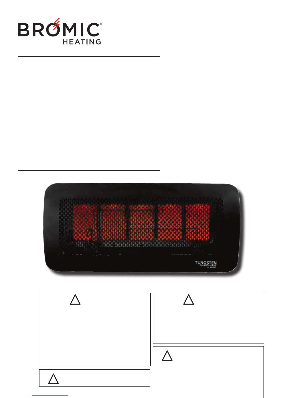
TUNGSTEN SMART-HEAT™
GAS HEATER
BY BROMIC
INSTALLATION, INSTRUCTION AND
SERVICE MANUAL
SUITABLE FOR GAS RADIANT HEATER MODELS:
TUNGSTEN 300 - BURNER AND TUNGSTEN 500 - BURNER
ENGLISH VERSION FROM PAGES 1 - 27
!
!
!
DANGER
If you smell gas:
1. Shut o gas to the appliance
2. Extinguish any open ame
3. If odor continues, keep away from the
appliance and immediately call your gas
supplier or re department.
Do not store or use gasoline or other amable
vapor and liquids in the vicinity of this or any
other appliance.
An LP-cylinder not connected for use shall not be
stored in the vicinity of this or any other appliance.
WARNING: For Outdoors Use Only.
WARNING
WARNING: Improper installation,
adjustment, alteration, service or maintenance
can cause property damage, injury or death.
Read the installation, operating and
maintenance instructions thoroughly before
installing or servicing this equipment.
!
Page 2
Head Office: 1 Suttor Street, Silverwater, Sydney, NSW 2128 Australia
Telephone: 1300 276 642 (within Australia) or +61 2 9748 3900 (from overseas) Fax: +61 2 9748 4289
Email: [email protected] Web: www.bromicheating.com
!
IMPORTANT
This manual contains important information about the assembly, operation, and maintenance
of Tungsten Smart-Heat Series Heaters. Please pay close attention to the important safety
information shown throughout this instruction manual. Any safety information will be accompanied
by the following safety alert symbols:
DANGER, WARNING, IMPORTANT
UÊREAD THIS MANUAL CAREFULLY before installing or
servicing this product.
UÊImproper installation, operation, or maintenance can result in
death, severe injury, or property damage.
UÊInstallation must be carried out by Authorized person/s in
accordance with local codes, or in the absence of local codes,
with the National Fuel Gas Code, ANSI Z223.1/NFPA 54,
Natural Gas and Propane Installation Code, CSA B149.1, or
Propane Storage and Handling Code, B149.2.
UÊThe heater, when installed, must be electrically grounded in
accordance with local codes or, in the absence of local codes,
with the National Electrical code, ANSI/NFPA 70 or the
Canadian Electrical Code, CSA C22.1.
UÊThis appliance is to be used ONLY for outdoor use
UÊWhen installed outdoors this appliance MUST be protected
from rain.
!!!
Page 3
CONTENTS
IMPORTANT NOTES & WARNINGS 4
PRODUCT OVERVIEW 5
PRODUCT DESCRIPTION 5
SPECIFICATIONS 5
GENERAL INFORMATION 6
PRODUCT FEATURES 6
INSTALLATION REQUIREMENTS 6
GAS REQUIREMENTS 6
INSTALLATION CLEARANCES 7
INSTALLATION INSTRUCTIONS 8
HEATER INSTALLATION INSTRUCTIONS 8
GAS SUPPLY INSTALLATION 12
POWER SUPPLY INSTALLATION 12
LEAKAGE TEST 12
HEAT DEFLECTOR INSTALLATION INSTRUCTIONS 13
CEILING MOUNT POLE INSTALLATION INSTRUCTIONS 13
OPERATING INSTRUCTIONS 14
TURNING THE APPLIANCE ON 14
TURNING THE APPLIANCE OFF 14
MAINTENANCE AND SERVICING 14
REGULAR SERVICE REQUIREMENTS 14
EXTERIOR SERVICING 14
OPTIMUM MOUNTING DISTANCE 15
HONEYWELL CONTROL 15
HONEYWELL VALVE 16
OPERATION DATA - FENWAL CONTROL BOX 17
DUNGS GAS VALVE 18
WHITE RODGERS GAS VALVE 18
WIRING DIAGRAM 19
REPLACEMENT PARTS 22
POST-INSTALLATION REPORT 24
TROUBLE SHOOTING 25
Page 4
IMPORTANT NOTES AND WARNINGS
!
WARNING
UÊTHIS APPLIANCE SHALL NOT BE INSTALLED OR USED
IN RESIDENTIAL DOMESTIC INDOOR AREAS
UÊCHILDREN AND ADULTS SHOULD BE ALERTED TO THE
HAZARDS OF HIGH SURFACE TEMPERATURES AND
SHOULD STAY AWAY TO AVOID BURNS OR CLOTHING
IGNITION
UÊYOUNG CHILDREN SHOULD BE CAREFULLY
SUPERVISED WHEN THEY ARE IN THE AREA OF THE
HEATER
UÊDO NOT USE OR STORE FLAMMABLE MATERIALS
NEAR THIS APPLIANCE
UÊCLOTHING OR FLAMMABLE MATERIALS SHOULD NOT
BE HUNG FROM THE HEATER OR PLACED ON OR
NEAR THE HEATER
UÊDO NOT SPRAY AEROSOLS OR FLAMMABLE MATERIALS
IN THE VACINITY OF THIS APPLIANCE WHILE IT IS IN
OPERATION
UÊANY GUARD OR OTHER PROTECTIVE DEVICE
REMOVED FOR SERVICING THE HEATER (conducted by
an authorized person) MUST BE REPLACED PRIOR TO
OPERATING THE HEATER
UÊINSTALLATION AND REPAIR SHOULD BE DONE BY A
QUALIFIED SERVICE PERSON. THE HEATER SHOULD
BE INSPECTED BEFORE USE AND AT LEAST ANNUALLY
BY A QUALIFIED SERVICE PERSON
Failure to follow the warnings and instructions in this manual
could result in severe personal injury, death or property
damage.
UÊThis Installation, Operation and Maintenance manual
should not be removed from the site of installation.
UÊInstaller should leave manual with the customer for future
reference.
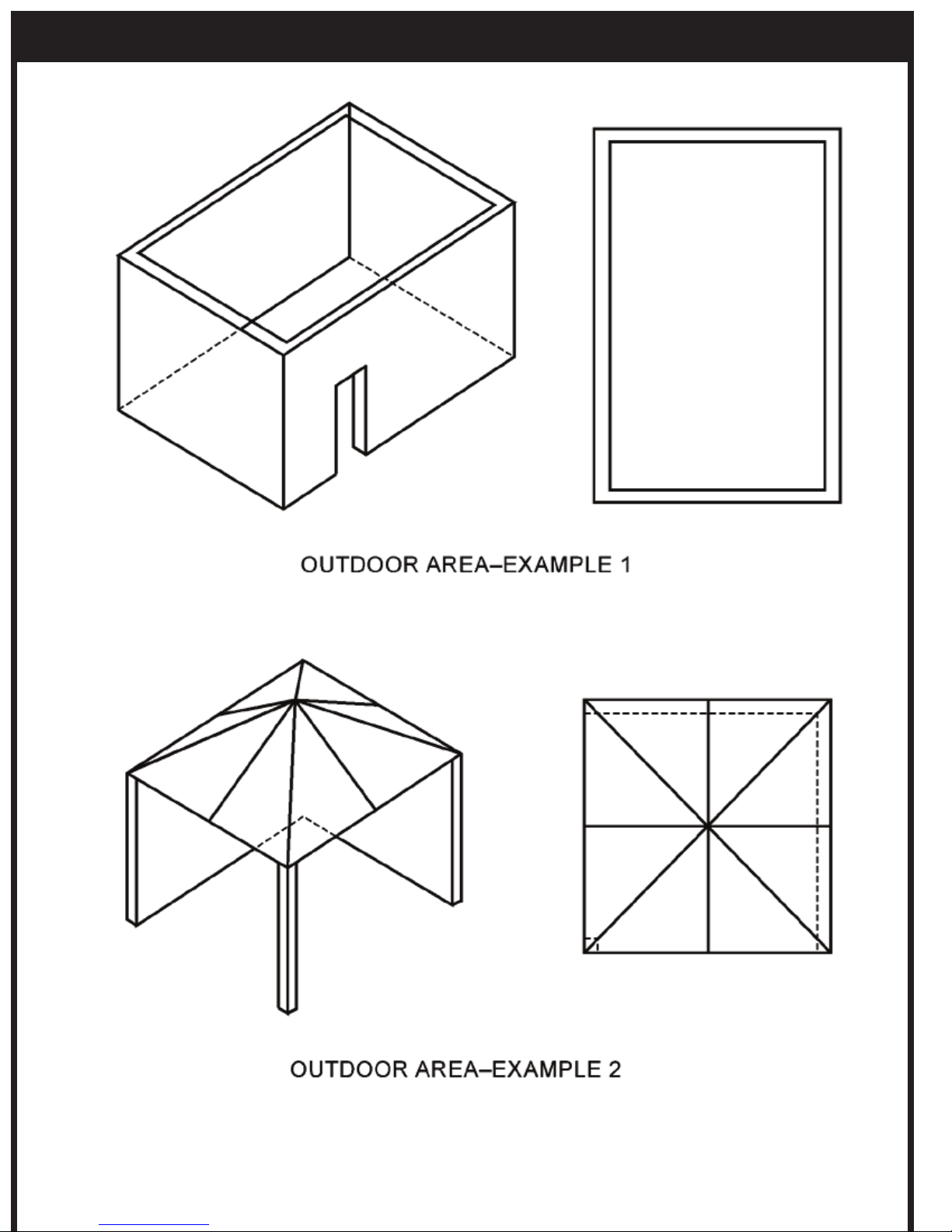
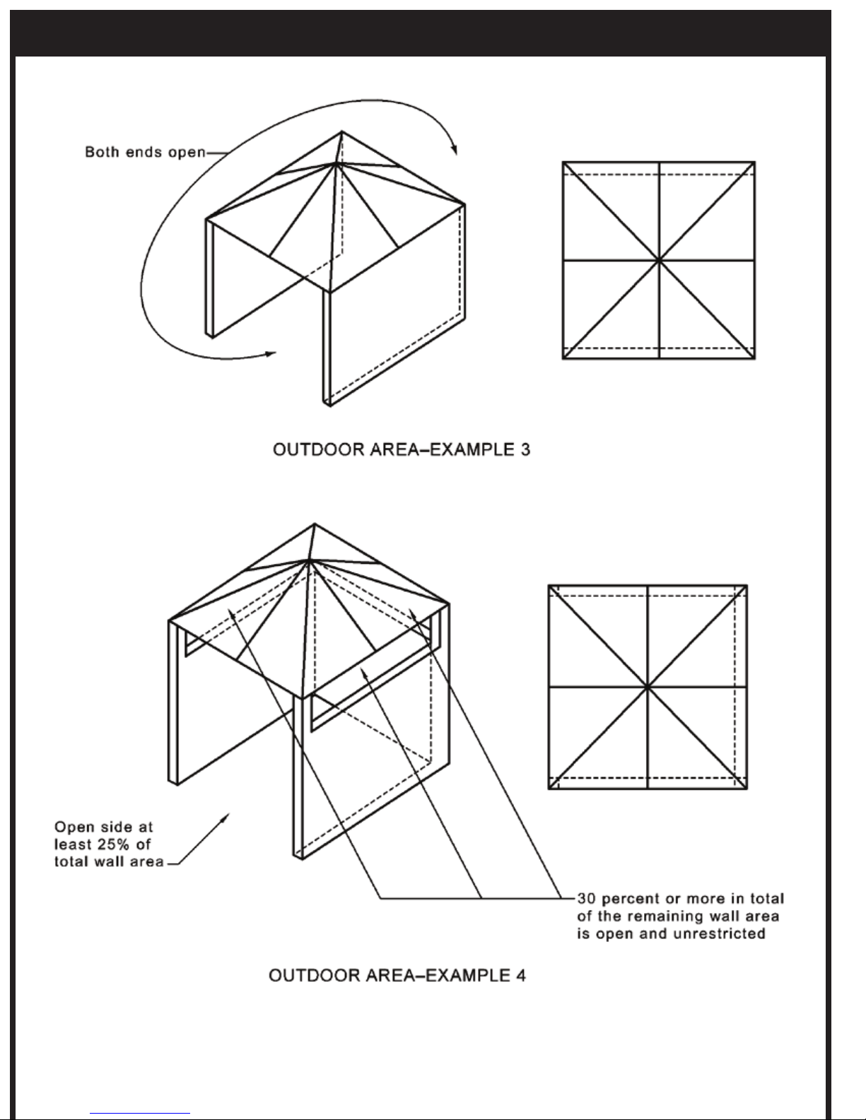
UÊThis Appliance is for outdoor areas only. (see attached
diagrammatical representations of outdoor areas
“Appendix A”).
UÊDo not perform maintenance until heater has been
turned off, power disconnected, and heater temperature
has cooled to room temperature.
UÊDo not expose the burner to water or moisture. THE
APPLIANCE IS TO BE PROTECTED FROM RAIN.
UÊDo not use the heater if any of these parts are exposed
to water until the appliance is inspected or repaired by
an authorized service person.
UÊThe installer is to ensure that the requirements of the local
authority, local gas fitting regulations, municipal building
codes, and any other relevant statutory regulations are
carried out.
UÊCertain materials or items, when stored under or near the
appliance, will be subjected to radiant heat and could
be seriously damaged. Ensure combustible materials eg.
overhead structures, walls, floors, furniture, fixtures and
plants are kept at least 3ft from the top and side.
UÊThe whole gas system, hose assembly, regulator, pipes,
and burner should be inspected for damage and leaks
before use and at least annually by an authorized person
for the life of the heater.
UÊDo not use the heater until all connections have been
leak tested by an authorized person.
UÊInspect the hose assembly before each use of the
appliance.
UÊThe hose assembly must be replaced prior to the
appliance being put into operation if there is evidence of
excessive abrasion or wear, or if the hose is damaged.
UÊThe replacement hose assembly must be CSA
approved.
UÊThe hose assembly is not to be located in areas where
the hose may be subject to accidental damage
UÊThis radiant heater is NOT intended to be installed on
recreational vehicles and/or boats.
UÊRepair to be carried out ONLY by an authorized person.
UÊImproper installation, adjustment, or alteration can cause
personal injury, property damage, or even death.
UÊDo not attempt to alter the unit in any manner.
UÊRemove transit protection before use.
UÊNever operate the heater in an explosive environment
such as areas where gasorline or other flammable liquids
or vapours are stored.
UÊTurn off the gas supply immediately if smell of gas is
detected.
UÊDo not paint any surface of the heater.
UÊDo not throw objects at the heater.
UÊControl compartment, burner and circulation air
passageways of the heater must be kept clean. Frequent
cleaning may be required as necessary.
UÊTurn Gas Supply off when not in use.
UÊCheck the heater immediately if any of the following
occurs:
» The heater does not reach temperature.
» The burner makes popping noise during use (a
slight noise is normal when the burner is ignited or
extinguished).
UÊYoung children should be supervised to ensure that they
don’t play with the appliance.
UÊThis appliance is not intended for use by young or infirm
persons unless they have been adequately supervised
by a responsible person to ensure that they can use the
appliance safely.
UÊCheck for damage to the appliance regularly. If damage
to the cord, plug or appliance is suspected, discontinue
use immediately and contact the supplier or qualified
person for repair.
UÊIf the cord, plug or appliance is damaged, unplug from
the outlet, discontinue use immediately, and only an
authorized person or similar may repair the unit.
UÊAvoid inhaling fumes emitted from the heater’s first
use. Smoke and odour from the burning of oils used in
manufacturing will appear. Both the smoke and odour
will dissipate after approximately 30 minutes.
UÊEnsure that a watertight seal is maintained on the
electrical control box at all times
UÊRegularly check for damage to the rubber seals. If
damage to the rubber seals is suspected, discontinue
use immediately, switch off power and contact the place
of purchase or authorized service technician for repair.
Page 5
PRODUCT OVERVIEW
PRODUCT DESCRIPTION
The Tungsten Smart-Heat Gas Radiant Heaters are designed to provide effective outdoor heating to both commercial and
residential premises whilst offering an appealing design.
The heaters incorporate full function electronic controls, allowing them to be operated remotely from a conveniently located
switch. The heaters have been designed to withstand the rigors of the outdoors.
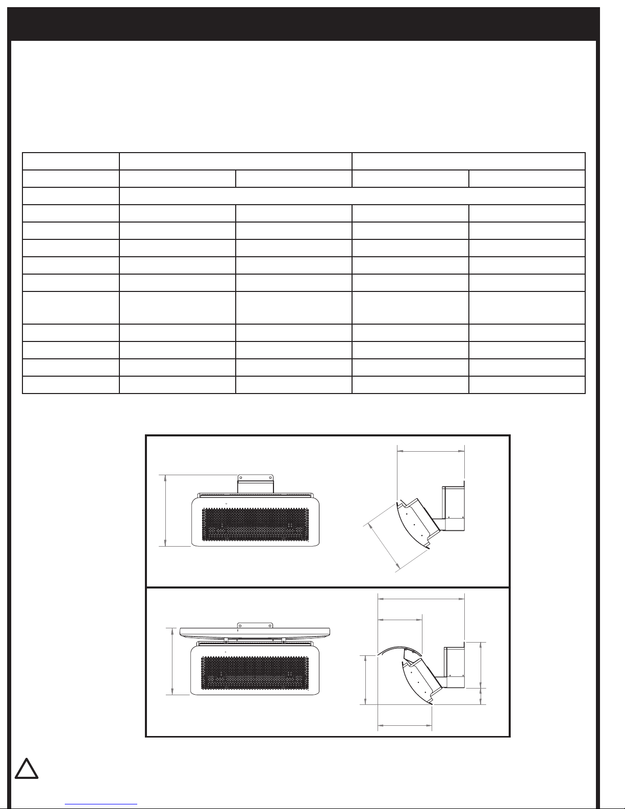
SPECIFICATIONS
501
26694
314
283
256
336
358
298
362
TUNGSTEN SMART-HEAT HEATER DIMENSIONAL DETAILS
With Heater
Deflector
Without Heater
Deflector
TUNGSTEN 300 TUNGSTEN 500
Gas type Propane (LPG) NATURAL GAS Propane (LPG) NATURAL GAS
Manufactured by BROMIC HEATING PTY LTD - 1 SUTTOR ST SILVERWATER, NSW, 2128, SYDNEY AUSTRALIA.
CSA Approval No. 2345658 2345658 2345658 2345658
Gas Consumption 26,000 BTU 26,000 BTU 43,000 BTU 43,000 BTU
Gas Type Propane Gas (LPG) Only Natural Gas Propane Gas (LPG) Only Natural Gas
Max. Line Pressure 14” W.C. 14” W.C. 14” W.C. 14” W.C.
Min. Line Pressure 11” W.C. 6” W.C. 11” W.C. 6” W.C.
Manifold Pressure
At Valve Test Point
10” W.C. 5” W.C. 10” W.C. 5” W.C.
Orifice Size 0.85mm 1.3mm 0.85mm 1.3mm
Weight 33lb 33lb 44lb 44lb
Voltage 110 Volt 110 Volt 110 Volt 110 Volt
Current < 2 Amp < 2 Amp < 2 Amp < 2 Amp
IMPORTANT
This appliance is NOT approved for indoor use and must be installed by authorized persons only in accordance with
local codes, or in the absence of local codes, with the National Fuel Gas Code, ANSI Z223.1/NFPA 54, Natural Gas and
!
Page 6
PRODUCT OVERVIEW CONTINUED...
GENERAL INFORMATION
The Tungsten Series Gas radiant heaters are suitable for outdoor spaces. In addition to the installation instructions provided,
authorized installers must abide by
local codes, or in the absence of local codes, with the National Fuel Gas Code, ANSI
Z223.1/NFPA 54, Natural Gas and Propane Installation Code, CSA B149.1, or Propane Storage and Handling Code,
B149.2. Please note that these standards are subject to change.
The heater is designed to function in winds up to 10mph. The heater is subject to reduced performance or failure in adverse
weather conditions such as high wind or extreme saturation.
PRODUCT FEATURES
Tungsten Smart-Heat gas radiant heaters are revolutionizing the outdoor heating industry by introducing groundbreaking
benefits never seen before in traditional gas or electric heaters. Tungsten Smart-Heat heaters have set the industry benchmark
with stylish good looks and world-first innovation.
Tungsten Smart-Heat heaters excel in the areas of:
UÊAesthetic appeal
UÊInnovation
UÊPerformance
UÊFlexibility
UÊCost effectiveness
For more detailed product information, visit www.bromicheating.com
INSTALLATION REQUIREMENTS
IMPORTANT
This appliance shall only be used in above ground open-air
situations with:
UÊnatural ventilation
UÊwithout stagnant areas
UÊwhere gas leakage and products of combustion are
rapidly dispersed by wind and natural convection
Any enclosure in which the appliance is used shall comply
with one of the following:
1. An enclosure with walls on all sides, but at least one
permanent opening at ground level (ref. Appendix A,
Example 1)
2. Within a partial enclosure that includes an overhead
cover and no more than two walls (ref. Appendix A,
Example 2)
3. Within a partial enclosure that includes an overhead
cover and more than two walls, the following shall apply:
UÊAt least 25% of the total wall area is completely open
(ref. Appendix A, Example 4), and
UÊAt least 30% of the remaining wall area is open and
unrestricted (ref. Appendix A, Example 4)
Note: The definition of outdoors is an above ground openair situation with natural ventilation, without stagnant areas,
where gas leakage and products of combustion are rapidly
dispersed by wind and natural convection.
!
GAS REQUIREMENTS
Tungsten LPG Models:
UÊUse Propane (LPG) gas only
UÊThe approved manifold pressure to the appliance is
10”W.C.
UÊThe MIN inlet pressure to the appliance is 11” W.C
UÊThe MAX inlet pressure to the appliance is 14” W.C
Tungsten Natural Gas Models:
UÊUse Natural Gas Only
UÊAlways use Natural Gas Regulator (supplied internal to
the gas valve)
UÊEnsure that Inlet pressure to the regulator does not
exceed 14” W.C.
UÊThe MIN inlet pressure to the appliance is 6” W.C
UÊThe approved manifold pressure to the appliance is
5”W.C.
Page 7
INSTALLATION REQUIREMENTS CONTINUED...
C
Minimum Mounting Height to Ground
B
A
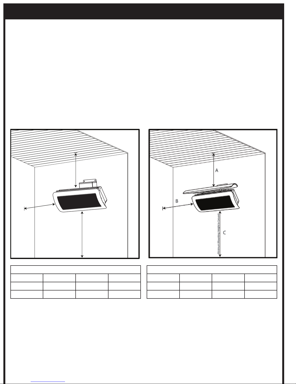
INSTALLATION CLEARANCES
When selecting the installation location for the Tungsten
Series Heaters, the following mounting clearances should be
followed.
Care should be taken to ensure that the heater is not installed:
UÊWhere heat/ignition can cause damage to gas cylinders/
lines
UÊNear other combustible materials
UÊIn open locations subject to rain
UÊIn indoor residential locations
UÊIn areas without sufficient clearances (refer below)
Note: When Installing with No protective cover, the following
installation clearances shall apply:
Minimum height to combustible materials
Model A B C
300 Series 3ft 3ft 8ft
500 Series 3ft 3ft 8ft
Note: When installing with the Tungsten Smart-Heat
Heat Shield (Part No. 2620165 or 2620166) the following
installation clearances Shall Apply:
Minimum height to combustible materials
Model A B C
300 Series 14” 3ft 8ft
500 Series 14” 3ft 8ft
Note: Heater should be installed in such a way so as to allow
adequate;
Clearance around air openings to combustion chamber
Clearance from combustible material
Provisions for accessibility and clearance for combustion and
ventilating air supply.
Page 8
INSTALLATION INSTRUCTIONS
!
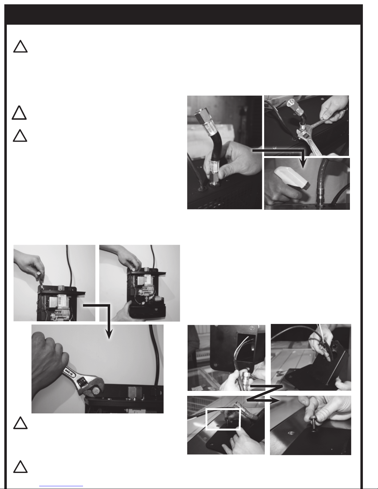
Step 1. Mount Wall Bracket/Control Housing To Wall:
UÊRemove Wall Bracket/Control Housing From
Packaging
UÊPlace the mounting bracket in position and mark
the fixing hole location on the wall. Drill holes using
appropriate drill size and type.
UÊAttach the bracket to the wall using appropriate
fixtures
Step 2. Connect CSA approved Flexible Gas Connector
(as supplied) to the inlet fitting on the heater
using 2 wrenches to tighten. Leak Test by applying
compressed air (1/2” PSI) to open end of flexible
hose. Spray gas fittings with a soapy water solution
and Check for leaks. Alternatively, leak check can be
done after assembly using inspection hole on bracket
arm. (see. leakage test section of this manual).
Step 3. Fix Mounting Arm to the back of the heater –
UÊSlide Gas Connector and Wiring Harness inside the
centre of the arm and have them exit through the
shaped cut-out on top surface of the arm
UÊEnsure that the arm faces downwards at a 55º angle
UÊPosition the 4 mounting holes on the arms plate
over the corresponding fixtures on the heater -
Manipulate the gas hose as necessary to allow for
correct alignment
UÊInsert and tighten 4 M6 bolts as provided to fit
mounting arm to heater.
WARNING
When mounting wall bracket/ control housing, ensure the
anchoring to the structure is of sufficient strength, quality
!
IMPORTANT
The Heater shall be firmly and securely attached to the wall.
For Brick and masonry, use M8 “Flush Head” “Dynabolts”
(or equivalent). For Wood / Timber fixtures, use suitable
screw fixings no less than 60mm in length.
!
WARNING:
Installation should be done by a qualied service person.
!
WARNING
This appliance must be installed and used in accordance
with local codes, or in the absence of local codes, with the
National Fuel Gas Code, ANSI Z223.1/NFPA 54, Natural Gas
and Propane Installation Code, CSA B149.1, or Propane
Storage and Handling Code, B149.2 and must meet all the
requirements stipulated in the “Installation Requirements”
section of this manual.
!
HEATER INSTALLATION INSTRUCTIONS
CAUTION
Please see specifications for the weight of the Heater. The
installer of the Tungsten Smart-Heat Radiant Heaters must
comply with all relevant State Occupational Health & Safety
Regulations.
Page 9
INSTALLATION INSTRUCTIONS CONTINUED...
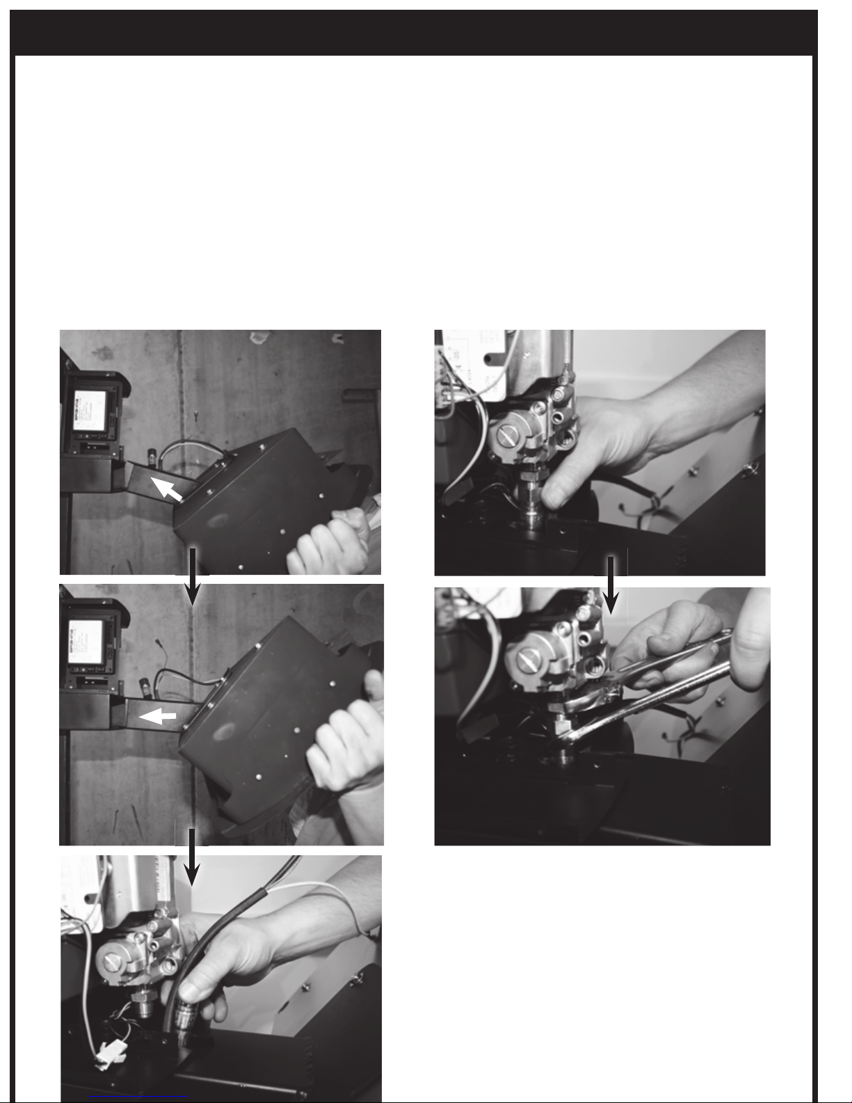
Step 4. Attach Heater to Wall Bracket/Control Housing
UÊRemove Front Cover from Control Housing
UÊAttach Heater to Wall Bracket/Control Housing
by inserting Mounting Arm into lower channel of
Wall Bracket. Ensure that the Gas Hose and Wiring
Harness slide through the groove on top side of
the control Housings lower channel and remain
undamaged by the metals edges during assembly.
UÊIt may be necessary to manipulate the gas Hose so
that the arm can slide into place.
TIP: Do not install the mounting pin at this point.
Step 5. Connect the CSA approved flexible connector to
the Gas Valve Outlet Fitting
UÊPosition heater and hose so that the gas hose and
fitting are in alignment
UÊNOTE: ensure that the hose nut and valve fitting are
parallel to one another and threads are engaged
correctly before tightening! Incorrect installation can
cause gas leaks and damage components.
TIP: Sliding the mounting arm inside the control
housing’s channel can help accurately Position the Gas
hose in place under the gas valve’s fitting.
UÊSpanner Tighten using 2 wrenches, and leak test
using soapy water (see section “leakage test”)
Page 10
INSTALLATION INSTRUCTIONS CONTINUED...
!
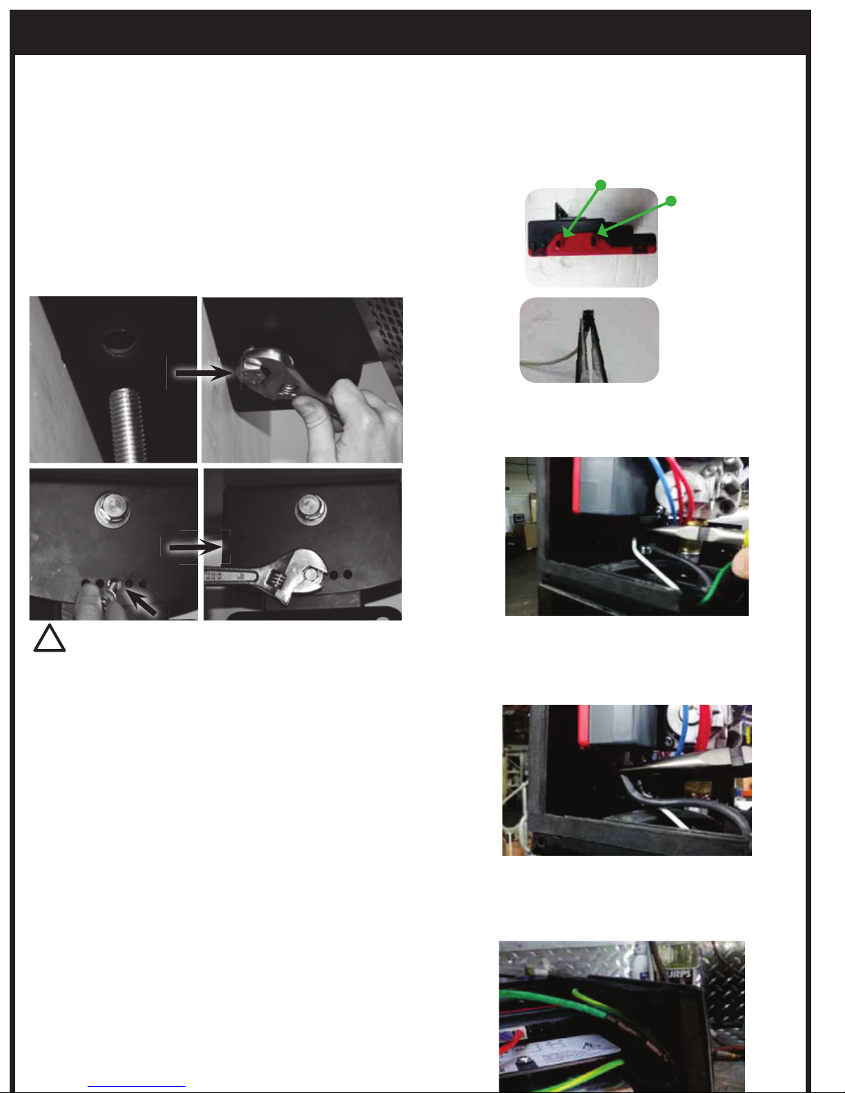
For Honeywell Control
UÊUsing a pair of needle nose pliers, grip the white
ionisation terminal as shown, being mindful of the
terminal pins of the control module.
Ignition (smaller terminal)
Ionisation
(larger terminal)
UÊInsert the ionisation terminal into the terminal pin
furthest away.
UÊEnsure that the terminal firmly clicks into place.
UÊInsert Repeat the process with the black ignition
cable inserting the terminal into the closer, smaller
terminal pin.
UÊInsert Plug the green earth terminal into one of the
available spade terminals attached to the top of the
wall bracket.
PLEASE NOTE: THERE IS NO NEED TO
REMOVE OR UNPLUG THE CONTROL
MODULE FROM THE GAS VALVE OR
WALL BRACKET ASSEMBLY
6. Insert Pivot Bolt
UÊPosition Arm so that the rear hole’s on the mounting
arm and Control Housing are in alignment
UÊInsert Bolt and washer (as supplied) through Control
Housing and Mount Arm, using the hole located on
the bottom surface of the Control Housing, towards
the rear. Spanner tighten in place
UÊSelect desired heater angle and insert the M6 Bolt
and washer (as supplied) through the bottom surface
of Control Housing into the mounting arm, using the
corresponding hole. (Heaters angle will be 0º, 10º or
20º). Spanner tighten in place
IMPORTANT
Electrical connections must be completed by trained and
authorized electrical technicians only!
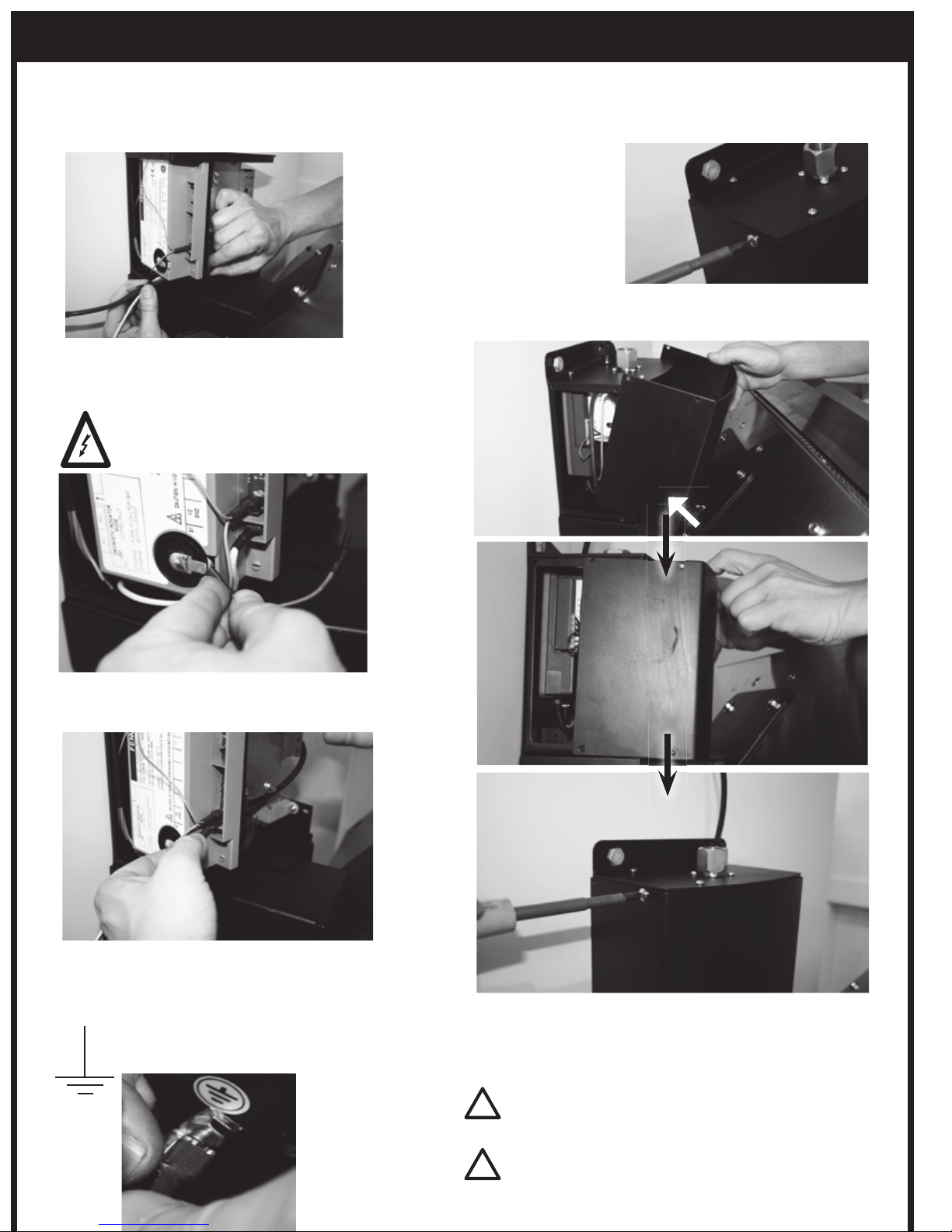
7. Connect the 3 wires from the heater by carefully following
the instructions below
Page 11
INSTALLATION INSTRUCTIONS CONTINUED...
8. Connect gas inlet fitting to mains gas supply in
accordance with local gas installation code and
gas supply installation section of manual. Leak test
with soapy water.
9. Fix Front cover to control housing using the 8xM4
screws provided.
10. Main Power supply connection is to completed in line
with instructions in the “Power supply installation”
section of this manual.
IMPORTANT
After gas installation and electrical installation is complete,
all gas lines should be tested for leaks using a soapy water
solution. See Section titled “Leakage Test” for further
!
IMPORTANT
Ensure that a water tight seal is maintained.
!
For Fenwal Control
UÊFeed wiring harness (3 wires) through opening
under Fenwal controller so that wires are
positioned to the left of the controller.
UÊConnect black ignition cable directly to control
box at terminal marked:
UÊConnect white ionisation cable directly to control
box at terminal marked: S1
UÊConnect ground terminal over ground tab,
attached to body of control housing and marked
with the symbol:
Page 12
INSTALLATION INSTRUCTIONS CONTINUED...
GAS SUPPLY INSTALLATION
Verify the type of gas supply complies with the appliance
rating plate, located at the back of the heater.
The inlet connection to the heater control box is a 1/2” NPT
Female.
The Control box has been fitted at the factory with an
approved manual isolating valve in accordance with local
Gas Installation Codes.
Tighten all the connections and then turn on the gas supply.
Check for gas leakage with a soapy water solution. (See
section titled “Leakage Test”).
Do not use an open flame to check for leaks.
When the heater is operating, check gas pressure at the test
point and ensure the manifold pressure to the heater is:
NG: 5” W.C.
PROPANE / LPG: 10” W.C
Gas supply pressure must be limited to 14” W.C. If gas line
pressure exceeds this level, a separate pressure reducing
regulator must be installed.
The appliance and its individual shutoff valve must be
disconnected from the gas supply piping system during any
pressure testing of that system at test pressures in excess of
1/2 psi.
The appliance must be isolated from the gas supply piping
system by closing its individual manual shutoff valve during
any pressure testing of the gas supply piping system at test
pressures equal to or less than 1/2 psig.
IMPORTANT
UÊAll gas supply installation work must be performed by
trained and authorized person(s) and comply with the
requirements of local Gas Installation Codes.
UÊAll Piping Joints should be tested for leaks with a
soapy water solution before use.
UÊGas hose must be located out of pathway where
people may trip over it, or in areas where the hose
may be subject to accidental damage.
!
POWER SUPPLY INSTALLATION
!
WARNING
This heater is equipped with a three-prong (grounding)
plug for your protection against shock hazard and should
be plugged directly into a properly grounded three-prong
receptacle. Do not cut or remove the grounding prong from
this plug.
The Tungsten Smart-Heat Heater comes standard with 36” of
power cord in addition to the Approved 3 pin power plug.
If an appropriate power socket is available, the heater can be
plugged into this power socket and operated using the on/
off switch supplied on the power socket. Alternatively, the
power installation can be tailored to suit the site requirements
by an Authorized Electrician.
Keep electrical supply cord away from any heated surface
and flue gasses.
Please Note:
Tungsten Smart-Heat Heaters do not have their own on/off
switch. Operation should be controlled via the main power
supply.
LEAKAGE TEST
Gas connections on the heater are leak tested at the factory
prior to shipment. A complete gas tightness check must be
performed at the installation site due to possible mishandling
in shipment or excessive pressure being applied to the
heater. Check ALL connections.
UÊThe heater must be checked with the gas supply turned
on.
UÊMake sure the safety control valve is in the OFF position.
UÊMake a soap solution of one part liquid detergent and
one part water. The soap solution can be applied with a
spray bottle, brush or rag. Soap bubbles will appear in
case of a leak.
UÊTurn the gas supply ON.
UÊIn case of a leak, turn off the gas supply. Tighten any
leaking fittings, then turn the gas supply on and recheck.
UÊNever leak test while smoking.
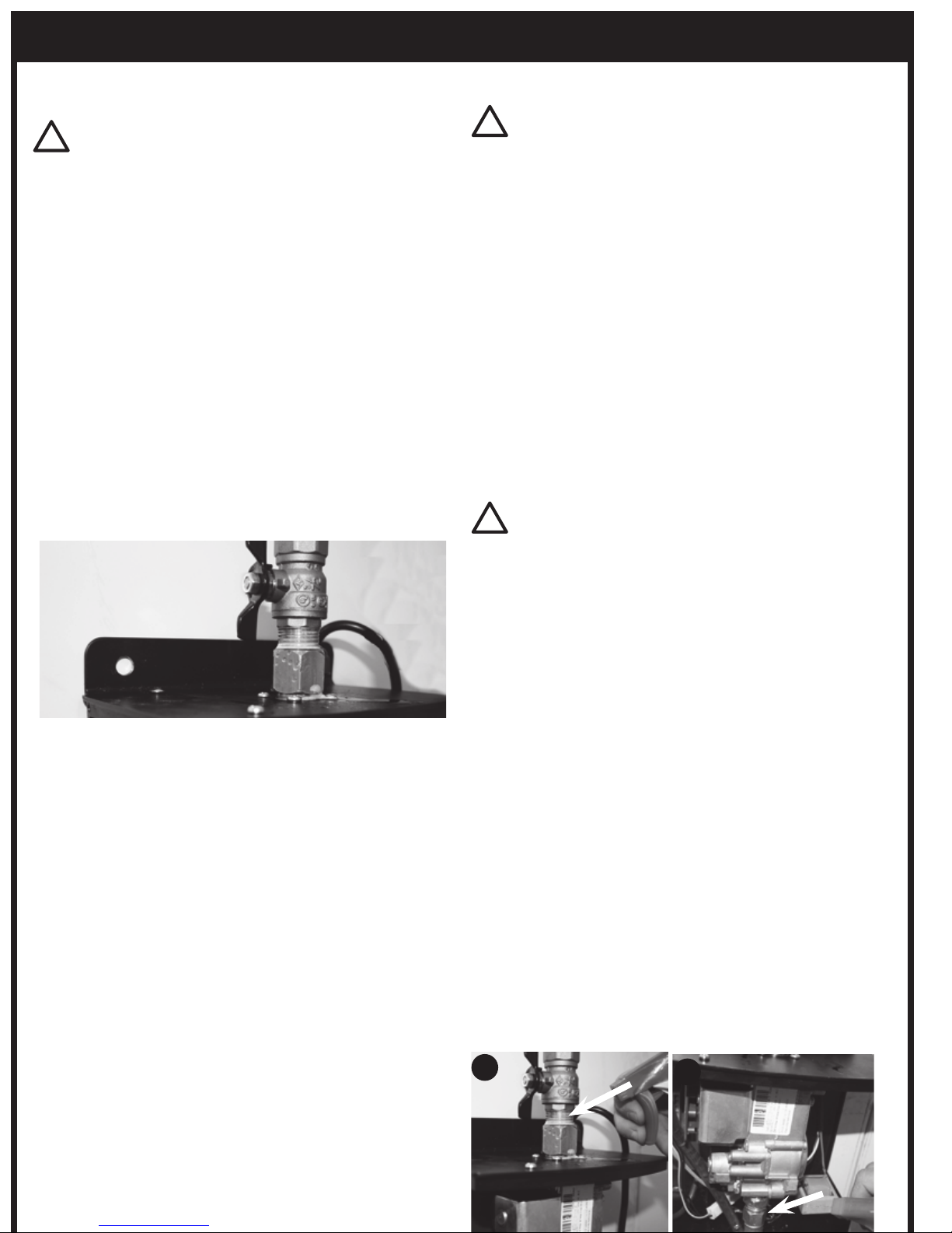
UÊThe following points MUST be leak checked before
operation.
WARNING
Ensure that power socket is switched off before plugging
in power cord.
!
1
2
Page 13
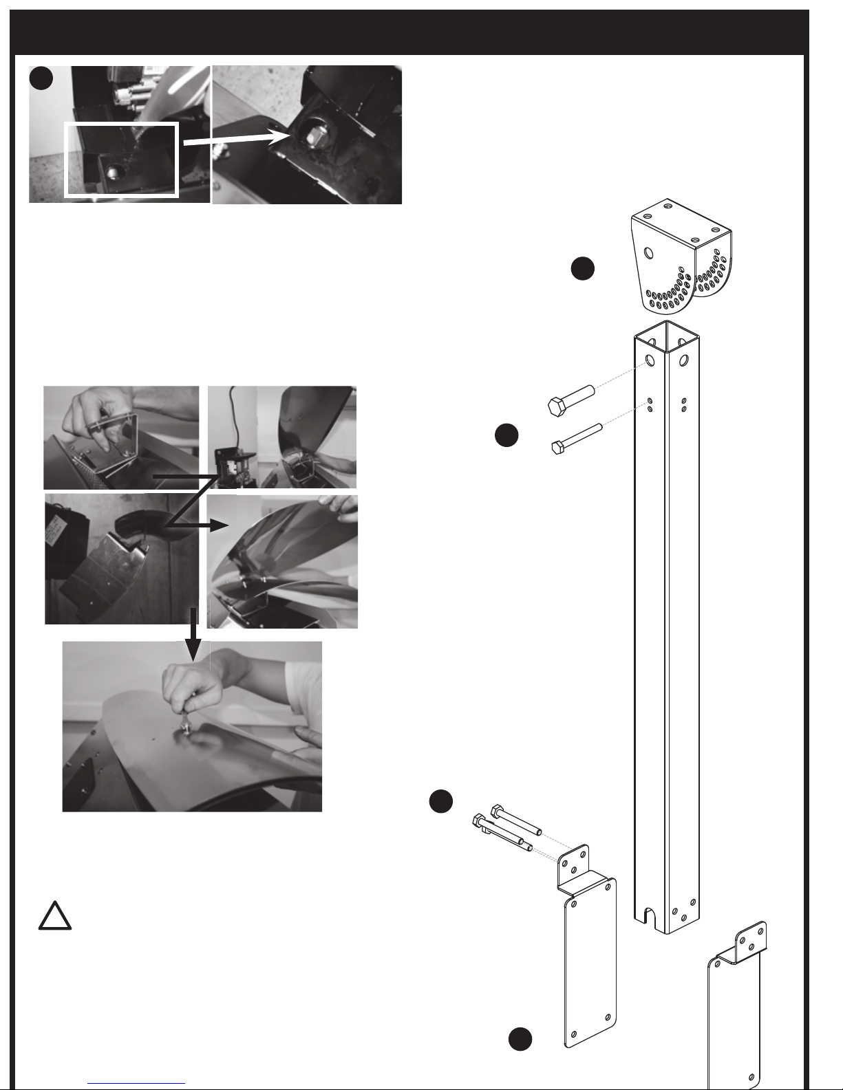
HEAT-DEFLECTOR INSTALLATION
1. Remove Heat Deflector and brackets from packaging
2. Mount Heat Deflector brackets to top side of heater
using 2 M4 screws provided
3. Attach inner skin of heat deflector to mounting brackets
using 4 M4 screws provided
4. Attach Outer skin to Inner skin using 4 M4 bolts provided.
CEILING POLE INSTALLATION
1. Mount Top Bracket to ceiling or support beam using
suitable fixings no less than 60mm length.
2. Assemble pole to the mounting bracket using the
M8x100mm and M19x100mm bolts, and fix using nuts
and washers (as supplied).
3. Assemble both lower paddles to the pole (back to back)
4. Fix Heater to Lower paddles using suitable fixtures.
NOTE: Tungsten Heating recommends running power and
gas lines, to the heater, inside the pole to reduce visibility
and likelihood of damage.
INSTALLATION INSTRUCTIONS CONTINUED...
1
2
3
4
3
!
WARNING
When mounting ceiling pole, ensure the anchoring to the
structure is of sufficient strength, quality and workmanship
to support the weight of the heater and any other load that
could be applied to the fixture.
Page 14
OPERATING INSTRUCTIONS
!
MAINTENANCE AND SERVICING
It is important that regular maintenance is carried out on the
heater to maintain efficient operation. All maintenance should
be carried out ONLY by authorized service personnel.
Control compartment, burner and circulation air passageways
of the heater must be kept clean. Inspect and clean at least
every six months or more frequently in adverse conditions.
Never obstruct the flow of combustion and ventilation
air. Always keep the appliance area clear and free from
combustible materials, gasoline and other flamable vapors
and liquids.
Do not clean heater with cleaners that are combustible or
corrosive.
REGULAR SERVICE REQUIREMENTS
1. CSA approved Gas Hose, located within the mounting
arm, must be checked at least once annually. The hose
must be replaced if there is any evidence of excessive
wear, or if the hose is damaged. The replacement hose
assembly must be CSA approved with 3/8”SAE flared
ends. To Check the Gas Hose, remove control housing
cover by removing 8 screws and slide cover outwards.
Alternatively, disassemble heater by reversing the
installation instructions as outlined in Installation section
of this handbook.
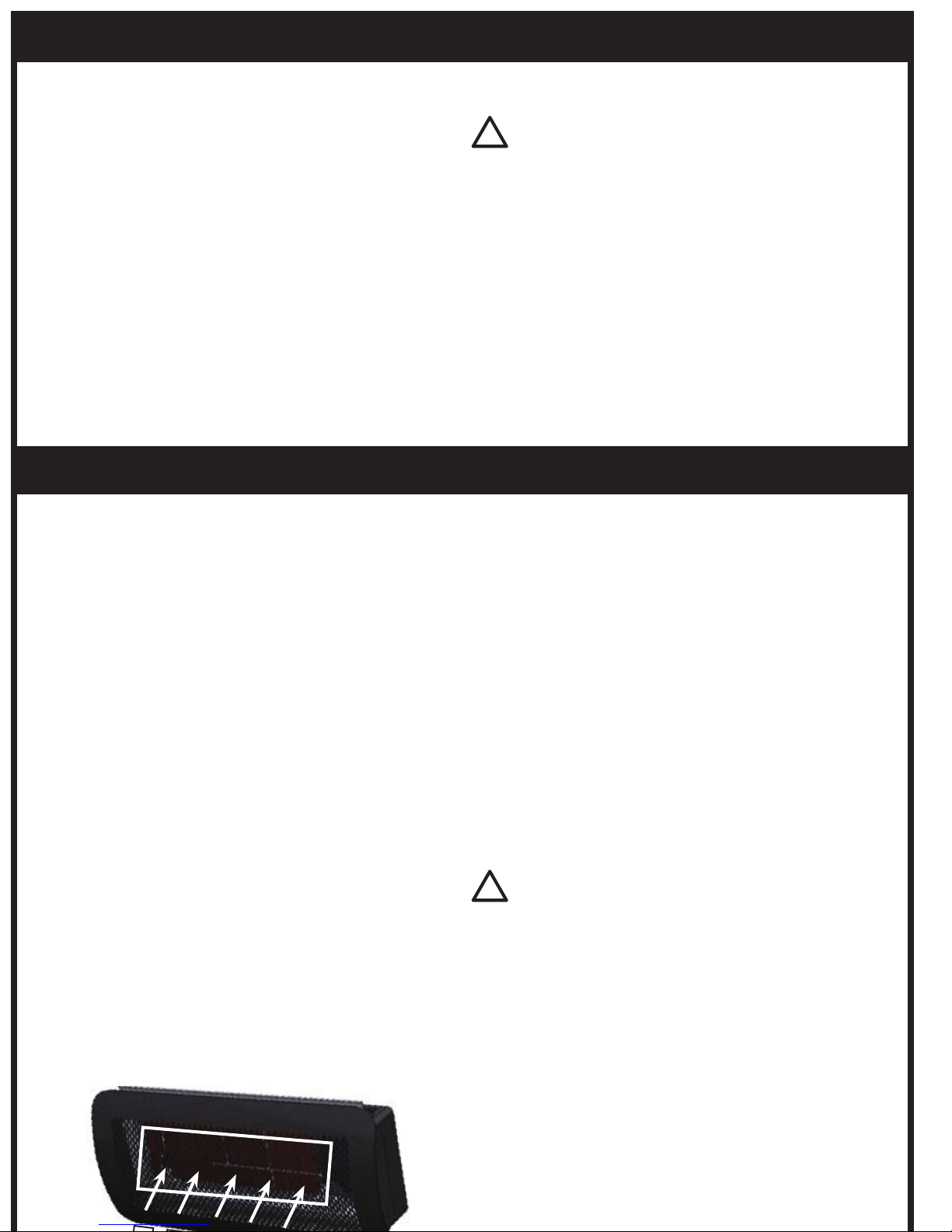
2. VISUALLY CHECK BURNER FLAMES. During heaters
function visually check that all burners are alight and
glowing hot. This can be done by observing the red
glow through the face, or by peering down the product
combustion passageway. Note: A slight variation in colour
is to be expected.
3. Clean burners: Burners can be cleaned by directing
compressed air (max20PSI) at outlet ports. Avoid directing
air at gasket material between ceramic tile and burner
cup.
4. Clean manifold and injectors: Undo gas hose from gas
valve outlet (heater should be switched off) and inject
compressed air (max20PSI) down the inlet fittings.
5. Clean dust and foreign matter from inside of heater
housing: Open up rear housing and clear dust using
compressed air (max20PSI) and a damp cloth.
6. Remove debris, spider and insect nests from, control
compartment, burner and circulation air passageways of
the heater with heavy-duty pipe cleaner or compressed
air to keep appliance clean and safe for use. Never clear
ports or other openings with toothpicks or other articles
that will break and block the ports.
7. In a salt-air environment, such as near an ocean, corrosion
occurs more quickly than normal. Check frequently for
corroded areas and repair them promptly.
IMPORTANT
More frequent cleaning may be required as necessary. It is
imperative that control compartment, burners and circulating
air passageways of the heater be kept clean.
!
EXTERIOR SERVICING
The exterior Tungsten Smart-Heat Heater components are
constructed from stainless steel, and high temperature coated
black paint. For all exterior black parts (excluding fascia trims),
a brushed finish has been used. This is not a coating and under
prolonged use, may slightly discolour from high temperatures
emitted by the heater. This is a normal occurrence and does
not affect the operation of the appliance.
NOTE: The appliance must be completly shutoff for a period
of 5 minutes before being relighted.
TURNING THE APPLIANCE ON
1. Ensure that gas installation and power installation has
been carried out in accordance with the manufacturers
instructions outlined in this document.
2. Turn on gas supply.
3. Ensure correct gas supply pressures are set.
4. Switch on power to heater.
5. If Gas heater does not light, turn power off.
6. Wait 5 seconds before turning power back on. If
heater does not ignite after 5 attempts, consult the
troubleshooting section of this manual, or contact Bromic
Heating Pty. Ltd for service information.
TURNING THE APPLIANCE OFF
1. For temporary shutdown, turn off power.
2. For permanent shutdown, turn off power and shut off gas supply.
IMPORTANT
Check the heater immediately if any of the following occurs:
UÊThe heater does not reach temperature.
UÊThe burner makes popping noise during use (a slight noise
is normal when the burner is ignited or extinguished).
Note: Avoid inhaling fumes emitted from the heater’s first
use. Smoke and odour from the burning of oils used in
manufacturing will appear. Both the smoke and odour will
dissipate after approximately 30 minutes.
Installers please Note:
When the installation and testing is completed, make sure
that the customer knows how to operate the heater. Leave
the operating instructions with the customer.
Page 15
!
A
B
B
OPERATION DATA - HONEYWELL CONTROL BOX
The following operation sequence is valid only where the
components are installed according to the manufactures
assembly and installation instructions. Please do not modify
the wiring configuration, gas train or any other part of the
heater assembly.
Application
The Honeywell electronic gas burner control system is suitable
for atmospheric gas burners for non-permanent operation.
Although the Honeywell unit is available non volatile lockout,
its configuration in the Tungsten Smart-Heat series heaters
limits it to volatile lockout, i.e. the restart from this condition
is possible by the interruption and subsequent restoration of
the mains power supply.
Features:
UÊCompliance with CSA standard for automatic gas burner
flame monitoring and control systems
UÊCompliance with EN 298 (European standard for
automatic gas burner flame monitoring and control
systems)
UÊCompliance with AGA (Australian standard for automatic
gas burner flame monitoring and control systems)
UÊFlame monitoring based on rectification property of the
TECHNICAL DATA
Supply voltage 110V-50/60Hz
Operating temperature -20°C / +60°C
Ambient humidity 90%max at 40°C
Protection degree IPX4
Timings:
Self Check time 1.5 s
Safety time (TS) 25 s
Drop out time on running flame failure 1 s
Power consumption, at start up 10VA
Power Consumption, Running 4VA
Ignition
Ignition Voltage 15kV with 40pF load
Spark repetition rate 33 Hz
Max. Cable length 1M
Recommended spark gap 0.14”
Consumption 2,5 VA
Spark energy 3 uAs
A
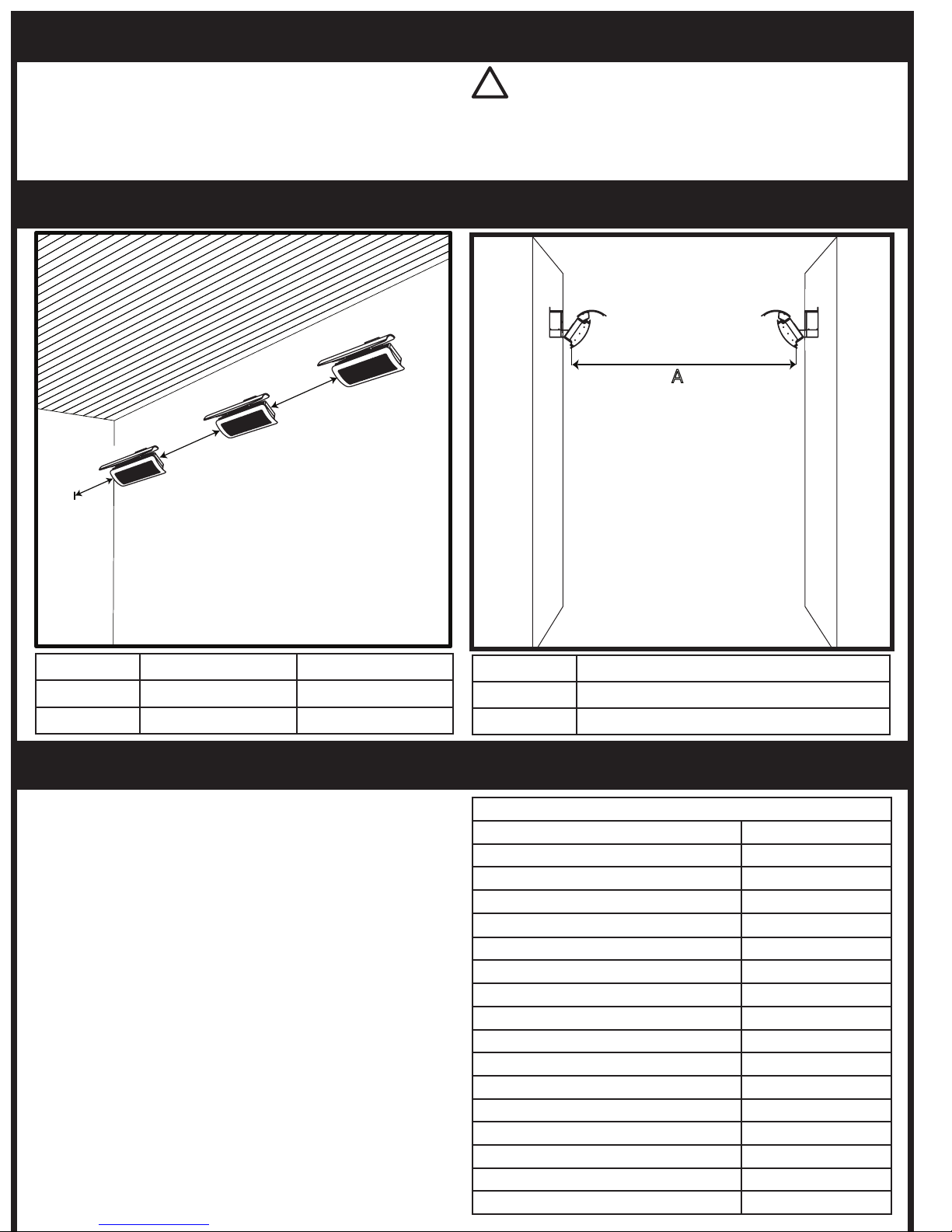
OPTIMUM MOUNTING DISTANCE
Replacement parts can be purchased to restore the heater to
its original appearance from Bromic Heating Pty Ltd. (Refer to
parts list in manual).
Model A B
300 Series 3ft 8 - 10ft
500 Series 3ft 8 - 10ft
Model A
300 Series 19 - 23ft
500 Series 26 - 29ft
IMPORTANT
Do not apply any additional surface coating to the heater under any
circumstances. Use of additional coating other than those applied
during manufacture could result in hazardous reactions such as
toxic fumes or fires. Additional coatings will void the warranty.
Page 16
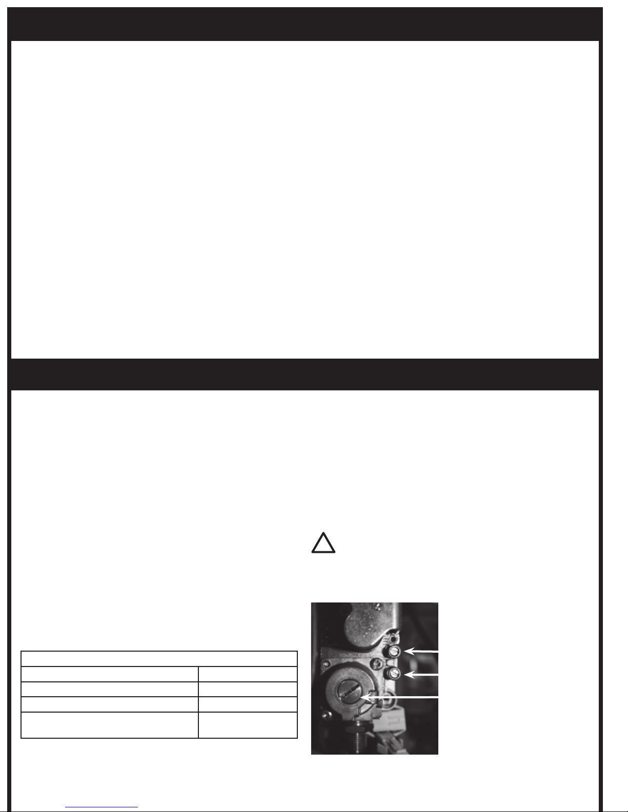
OPERATION DATA - HONEYWELL CONTROL BOX CONTINUED...
Inlet Pressure
Outlet Pressure
Regulator
IMPORTANT
Remember to place the regulator cover, outlet and inlet back
on.
!
Directions for use
UÊAutomatic controls are safety devices and shall not be
opened. The manufacturer’s responsibility and guarantee
are invalid if the control is unduly opened.
UÊA regulation shutdown must occur every 24hours to
enable the unit to check its own efficiency (systems for
non permanent operation)
UÊConnect and disconnect the unit only after switching off
the power supply
UÊAvoid exposing the unit to dripping water
UÊVentilation and the lowest temperature ensures the
longest life of the control
Electrical Installation
UÊLive and Neutral should be connected correctly; a mistake
could cause a dangerous situation.
UÊBefore starting the system check cables carefully for
incorrect installation
UÊThe earth terminal of the control, the metal frame of the
burner and the earth on the mains supply must be well
connected
Operation
At every start, the control unit proceeds to a self-checking
of its own components. During the pre-purge or waiting
time (TW) the internal circuit makes a test of the flame signal
amplifier. Extraneous light or fault in the amplifier will result
in the simulation of a flame which will prevent the control
from starting.
At the end of the waiting or pre-purge time, the gas valve is
energised and the ignition device is operated. In this way, the
safety time (TS) begins.
If a flame is detected during the safety time, the ignition
device is inhibited and the gas valve remains energised.
If the control does not detect any flame signal during the
safety time, at the end of safety time (TS), the unit proceeds
to lockout and the gas valve and ignition device are switched
off.
If the established flame signal is lost, (during the safety time
or during operation thereafter) this will cause the ignition
device to be reactivated within 1 second.
If the burner does not light within 25 seconds of ignition
reactivation, the heater will enter failure lockout mode and
must be reset.
OPERATION DATA HONEYWELL VALVE:
The VK series gas control have been specially developed for
application in domestic appliances. The Honeywell Gas Valve
is a multi-functional control which incorporates an adjustable
direct acting pressure regulator. It is designed for operation
on 220/240V.
Standard Specifications
UÊ1/2” G Female Pipe Thread connection
UÊAmbient Temperature Range of 0°C to 60°C
UÊCompact Size: 86.5mm x 63.5mm x 65.9mm
UÊ50mb Pressure Rating
UÊ1/2” x 1/2” (BSP- G) Inlet and Outlet
UÊEarthing terminal – 0.24” spade tab
UÊTamper resistant screws
UÊTop mounted coils that can be field replaced
TECHNICAL DATA
Max inlet working pressure 50 mbar
Installation group Group 2
Operating Temperature 0°C to 60°C
Voltage Ratings 220/240VAC
50/60Hz .52A
Adjust Regulator Pressure
UÊUnscrew the regulator cover.
UÊUnscrew the outlet plug to measure the outlet regulator
pressure by using manometer.
UÊAdjust the pressure by turning the regulator screw
clockwise or anti wise.
UÊAdjust the pressure according to appliance specification.
Page 17
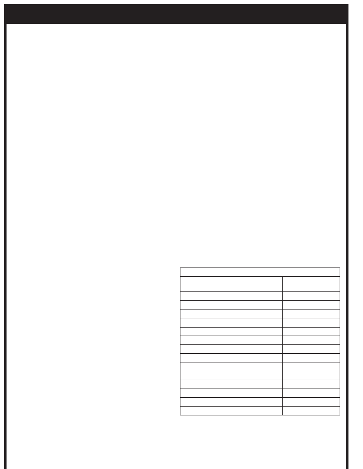
OPERATION DATA - FENWAL CONTROL BOX
The Series 35-60 is 24 VAC Microprocessor Based Direct
Spark Ignition Controls designed for use in all types of
heating applications. The control utilizes a microprocessor
to continually and safely monitor, analyze and control the
proper operation of the gas burner. The following operation
sequence is valid only where the components are installed
according to the manufacturers assembly and installation
instructions. Please do not modify the wiring configuration,
gas train or any other part of the heater assembly.
Application
The Fenwal electronic gas burner control system is suitable
for atmospheric gas burners for non-permanent operation.
The Fenwals configuration in the Tungsten Smart-Heat series
heaters limits it to volatile lockout, i.e. the restart from this
condition is possible by the interruption (for 5 seconds) and
subsequent restoration of the mains power supply.
Features:
UÊ24 VAC microprocessor based DSI control
UÊPressure switch monitoring
UÊSystem diagnostic LED
UÊAlarm output (normally closed contact)
UÊAutomatic reset 1 hour after lockout*
UÊCustom prepurge and interpurge timings**
UÊMultiple tries for ignition
UÊRemote or local flame sensing
UÊFlame sense test pins
Directions for use
Automatic controls are safety devices and shall not be
opened. The manufacturer’s responsibility and guarantee are
invalid if the control is unduly opened.
A regulation shutdown must occur every 24hours to
enable the unit to check its own efficiency (systems for non
permanent operation)
Connect and disconnect the unit only after switching off the
power supply
Avoid exposing the unit to dripping water
Ventilation and the lowest temperature ensures the longest
life of the control
Electrical Installation
UÊThe applicable state and local standards regarding
electrical safety must be respected.
UÊLive and Neutral should be connected correctly; a
mistake could cause a dangerous situation.
UÊBefore starting the system check cables carefully for
incorrect installation
UÊThe ground terminal of the control, the metal frame of
the burner and the ground on the mains supply must be
well connected
Operation
When a call for heat is received from the thermostat
supplying 24 volts to TH/W, the control will reset, perform a
self check routine, flash the diagnostic LED, and a pre-purge
delay begins. Following the pre-purge period the gas valve
is energized and sparks commence for the trial for ignition
period.
When flame is detected during the trial for ignition, sparks are
shutoff immediately and the gas valve remains energized. The
thermostat and main burner flame are constantly monitored
to assure the system continues to operate properly. When
the thermostat is satisfied and the demand for heat ends, the
main valve is de-energized immediately.
Should the main burner fail to light, or flame is not detected
during the trial for ignition period, the control will go into
lockout. The valve will be turned off immediately. Multi-try
Models will attempt two additional ignition trials before
going into lockout. The valve relay will be de-energized
immediately.
Recovery from lockout requires a manual reset by removing
24 volts from 24 VAC(R) for a period of 5 seconds. If there is
still a call for heat after one hour the control will automatically
reset and attempt to ignite the burner again.
If the established flame signal is lost the control will respond
within 0.8 seconds. The HV spark will be energized for a
trial ignition period in an attempt to relight the burner. If
the burner does not light the control will de-energize the
gas valve. Multi-try models will make two more attempts to
relight the burner. If the burner does not relight the control
will go into lock out as noted above. If flame is re-established,
normal operation resumes.
TECHNICAL DATA
Supply voltage 18 to 30 VAC 50-
60Hz
Operating temperature -40°F +176°F
Ambient humidity 95%max at 104°F
Protection degree IP00
Timings:
Self Check time 1.5 s
Safety time (TS) 10 s
Drop out time on running flame failure 0.8 s
Power consumption, at start up 300mA Max.
Power Consumption, Running 300mA Max.
Ignition
Ignition Voltage 15kV with 40pF load
Spark repetition rate 50/60 sparks/ sec.
Max. Cable length 1M
Recommended spark gap 3.5mm
Page 18
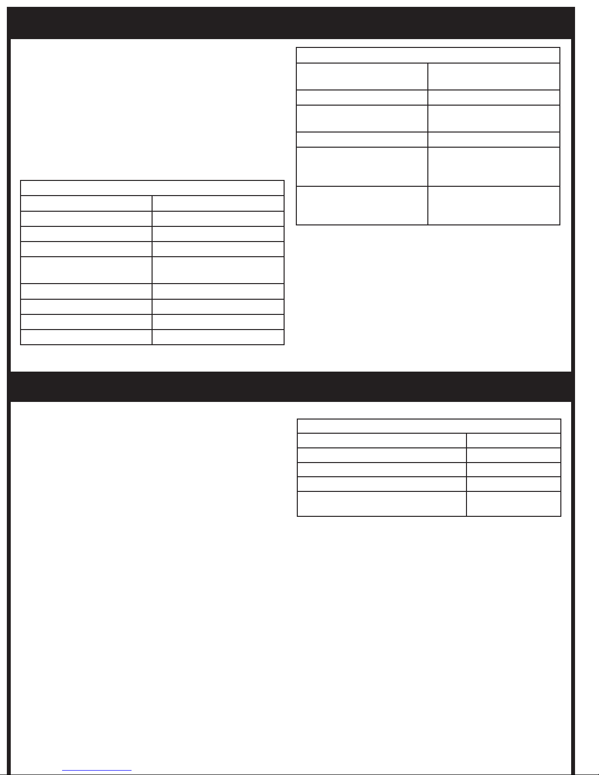
OPERATION DATA - DUNGS GAS VALVE
The Dungs GB Valve is a multifunctional Gas Control with
combined regulator and safety shutoff valves.
The pressure regulator includes a servo regulator to regulate
pressure fluctuations in the mains supply. This ensures a
precise volume flow and constant injector pressure.
To shut down the pressure regulator turn the setting device
25 times clockwise until a soft click can be heard.
Standard Specifications
TECHNICAL DATA
Gas Connection 1/2” RP
Max Inlet Pressure 65 mbar
Pressure Range 2.5mbar to 38mbar
Nominal Flow 3,3 m3/h (Air)
Ambient temperature 5 °F to -158 °F
32 °F to -158 °F at LPG
Automatic shut-off valves Class B as per EN 126
Group 2
Pressure Regulator Class C
Degree of protection IP40
TECHNICAL DATA
Opening Time Fast Opening <1sec
Slow Opening <10 sec
Closing Time <1 sec
Voltage Frequency ~(AC) 50 - 60 Hz 24 V +10
% – 15 %
Load of coil (24 V, 230 V) 2 x 5,5 VA
Electrical connection Molex System connection
coil or Option: Connection
box with integrated cable
Installation position Solenoid at any position
between vertical and horizontal axis.
OPERATION DATA - WHITE RODGERS VALVE
The White Rodgers Gas Valve is a compact multi-functional
control which incorporates an adjustable direct acting
pressure regulator. It operates on 240V.
Standard Specifications
UÊInlet Screen – will filter to 180 microns
UÊAmbient Temperature Range of 32°F to -140°F
UÊCompact Size: 86.5mm ( 3.4”) x 63.5mm (2.5”) x 65.9mm
(2.6”)
UÊ50mb Pressure Rating
UÊClass ‘B’ Group 2 Direct Acting Solenoid Valves with
high sealing force
UÊ3/8” x 3/8” (BSP PI.) Inlet and Outlet
UÊOpening time < 0.25 seconds
UÊClosing time < 0.25 seconds
UÊEarthing terminal – 6mm spade tab
UÊTamper resistant screws
TECHNICAL DATA
Max Working pressure 50 mbar
Installation group Group 2
Operating Temperature 32°F to -140°F
Regulator adjustment range 9.2 to 13.7 mbar
Voltage Ratings 24VAC
50/60Hz
UÊTop mounted coils and electronics that can be field
replaced without entering the gas stream.
Page 19
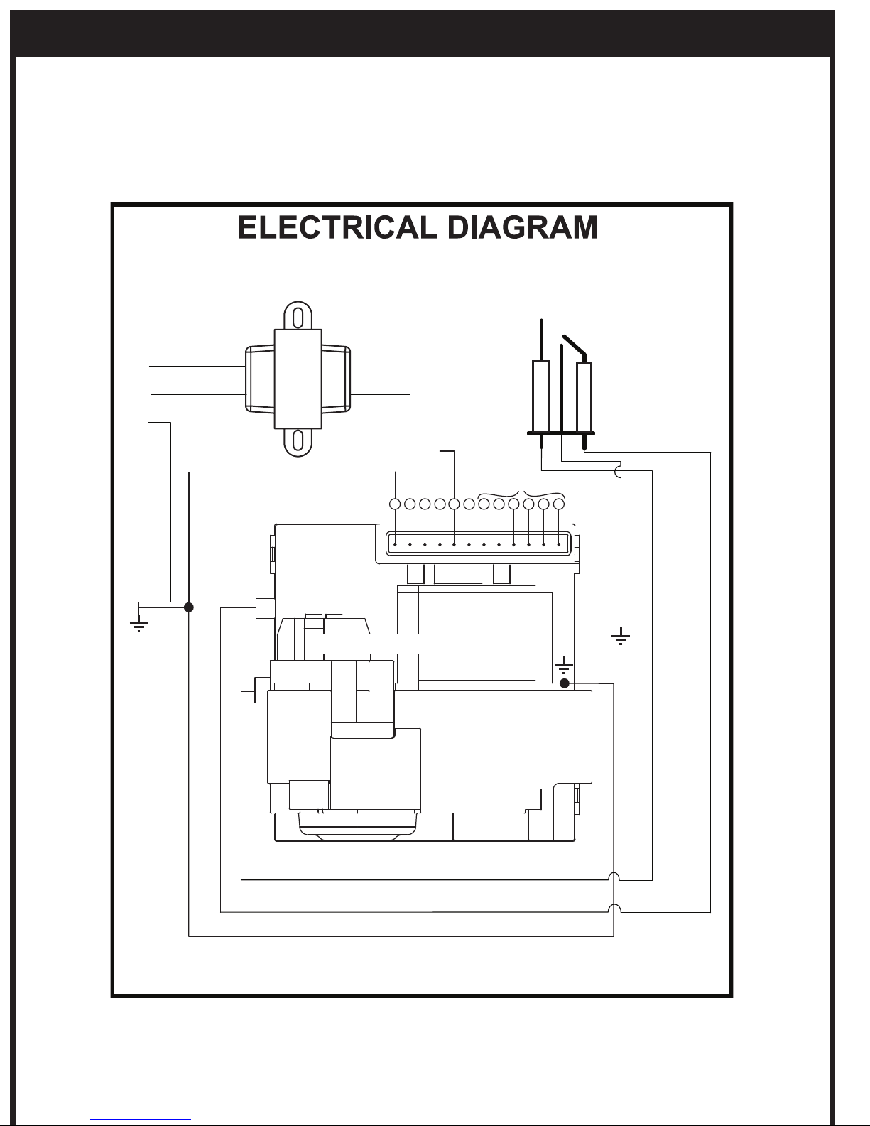
WIRING DIAGRAM - HONEYWELL CONTROL, HONEYWELL GAS VALVE
12
11
10
9
8
7
6
5
4
3
2
1
N
L
E
White
Black 110 V
N/A
Yellow/Green
Yellow/Green
Yellow/Green
Green
White
Black
Ignition +
Ionisation
HONEYWELL
Red 230 V
Blue
Purple
Purple
Note:
If any of the original wire as supplied with the heater must be replaced, it must be replaced with 18AWG, 90ºC type UL
approved wire or its equivalent. If Transformer must be replaced, a UL approved model of similar type must be used.
SEE INSTRUCTION MANUAL FOR DETAILS ON HOW
TO CONNECT THE ELECTRICAL COMPONENTS.
TRANSFORMER
Page 20
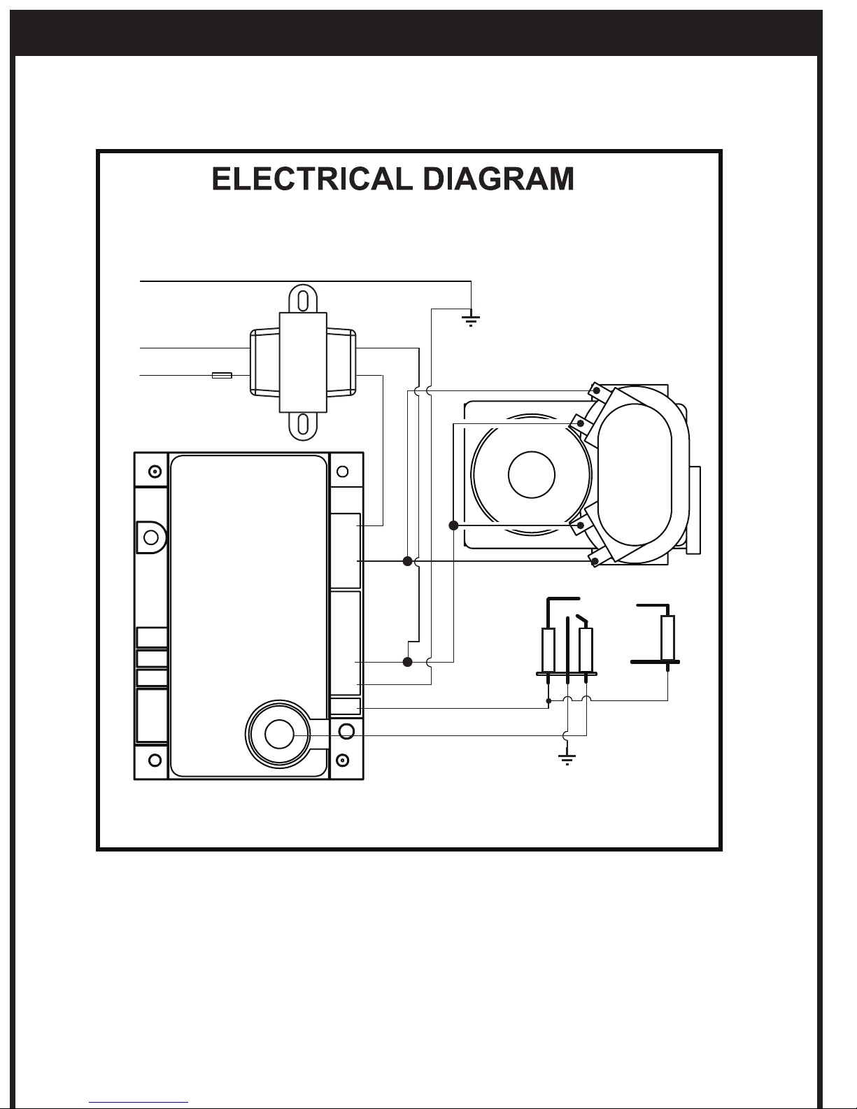
Note:
If any of the original wire as supplied with the heater must be replaced, it must be replaced with 18AWG, 90ºC type UL
approved wire or its equivalent. If Transformer must be replaced, a UL approved model of similar type must be used.
ionisation
WIRING DIAGRAM - FENWAL CONTROL, WHITE RODGERS GAS VALVE
SEE INSTRUCTION MANUAL FOR DETAILS ON HOW
TO CONNECT THE ELECTRICAL COMPONENTS.
Green
E
White
N
Black - 110 V
L
FENWAL
TRANSFORMER
GND.
T H
V 1
V 2
S 1.
Blue
24 V
Red
Orange
Blue
Yellow/Green
White
Black HT Cable
Ignition + ionisation
WHITE
RODGERS
Page 21
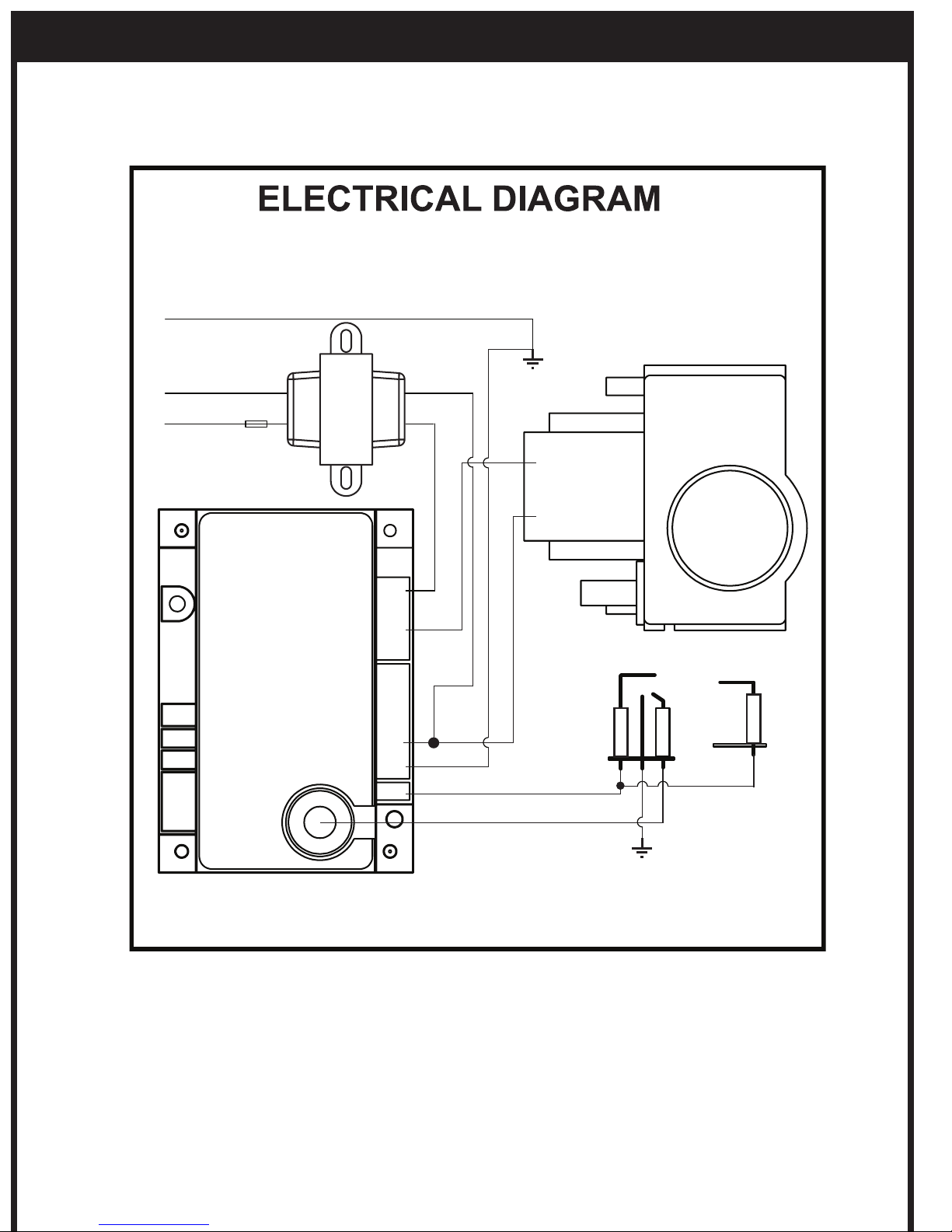
Note:
If any of the original wire as supplied with the heater must be replaced, it must be replaced with 18AWG, 90ºC type UL
approved wire or its equivalent. If Transformer must be replaced, a UL approved model of similar type must be used.
Ignition + Ionisation
Ionisation
WIRING DIAGRAM - FENWAL CONTROL, DUNGS GAS VALVE
SEE INSTRUCTION MANUAL FOR DETAILS ON HOW
TO CONNECT THE ELECTRICAL COMPONENTS.
Green
E
White
N
Black - 110 V
L
FENWAL
TRANSFORMER
GND.
T H
V 1
V 2
S 1.
Blue
24 V
Red
Orange
Blue
Yellow/Green
White
Black HT Cable
DUNGS
Page 22
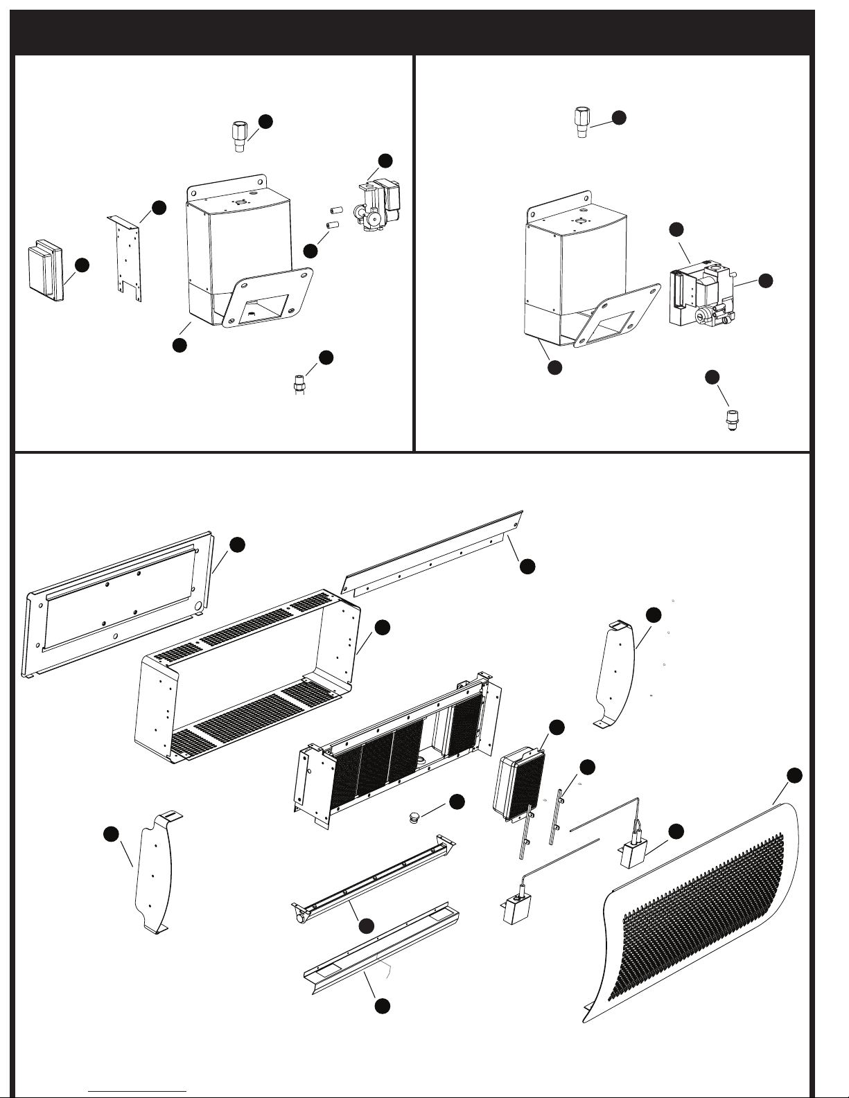
REPLACEMENT PARTS
6
22
7
17
13
16
19
20
15
13
14
19
White Rodger Honeywell
9
12
8
10
5
24
3
23
4
1
11
2
Page 23
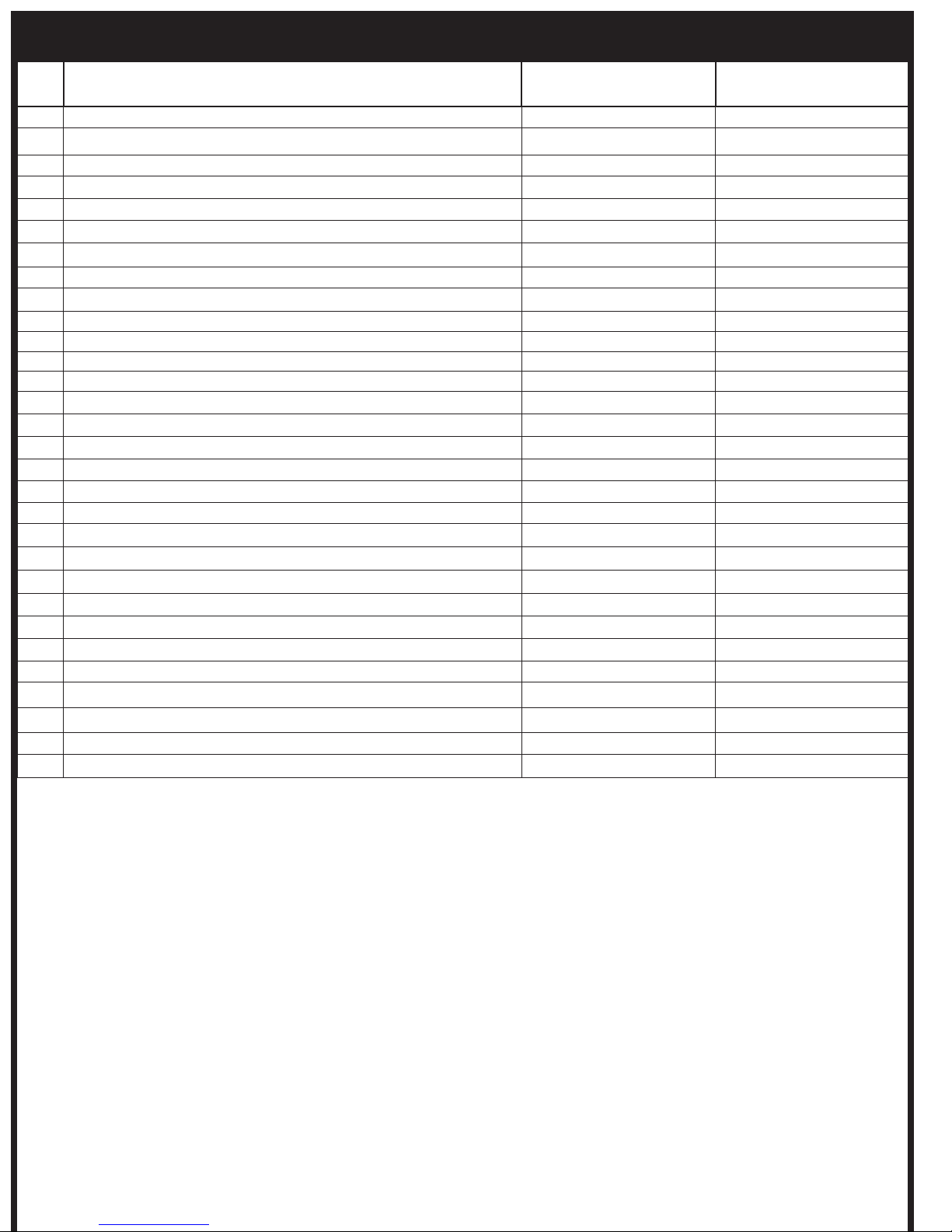
REPLACEMENT PARTS DISCRIPTION
No. Description Part No. 300 Series Part No. 500 Series
1 Front Cover BH8080039 BH8080040
2 Flame Protector BH8080041 BH8080042
3 Right Side Mount BH8080043 BH8080043
4 Left Side Mount BH8080044 BH8080044
5 Ionization Holder Assembly - including Tungsten spacer BH8080045 BH8080045
6 White Rodger Spacer
7 Control Mount
8 Rear Housing BH8080046 BH8080047
9 Rear Cover Assembly BH8080048 BH8080049
10 Burner BH8080030 BH8080030
11 Wiring Harness + Ignitor Assembly- Honeywell BH8080012 BH8080013
12 Inner Skin BH8080031 BH8080032
13 Wall Bracket Assembly BH8080001 BH8080001
14 Honeywall Control BH8080015 BH8080015
15 Honeywell Gas Valve BH8080014 BH8080014
16 Fenwal Control
17 White Rodger 24V Gas Valve
18 Intentionally left blank
19 Gas Inlet Fitting (Honeywell 1/2” Gas Valve) BH8080035 BH8080035
20 Gas Outlet Fittings ( Honeywell 1/2”Gas Valve) BH8080036 BH8080036
21 Intentionally left blank
22 Gas Outlet Fitting (WhiteRodgers Gas Valve)
23 Manifold Assembly - Natural Gas BH8080037 BH8080038
23 Manifold Assembly - LPG BH8080093 BH8080090
24 Injector (LPG) BH8080016 BH8080016
24 Injector (NG) BH8080017 BH8080017
25 Wall Bracket Replacement Screw Set including Gas Hose BH8080051 BH8080051
26 Intentionally left blank
27 Deflector Screw Set including arm BH8080052 BH8080052
28 Transformer – 110V-230V (Honeywall) BH8080050 BH8080050
Note: For more information on obtaining spare parts contact the place of purchase or
Head Office: 1 Suttor Street, Silverwater, Sydney, NSW 2128 Australia
Telephone: 1300 276 642 (within Australia) or +61 2 9748 3900 (from overseas) Fax: +61 2 9748 4289
BROMIC HEATING
Page 24
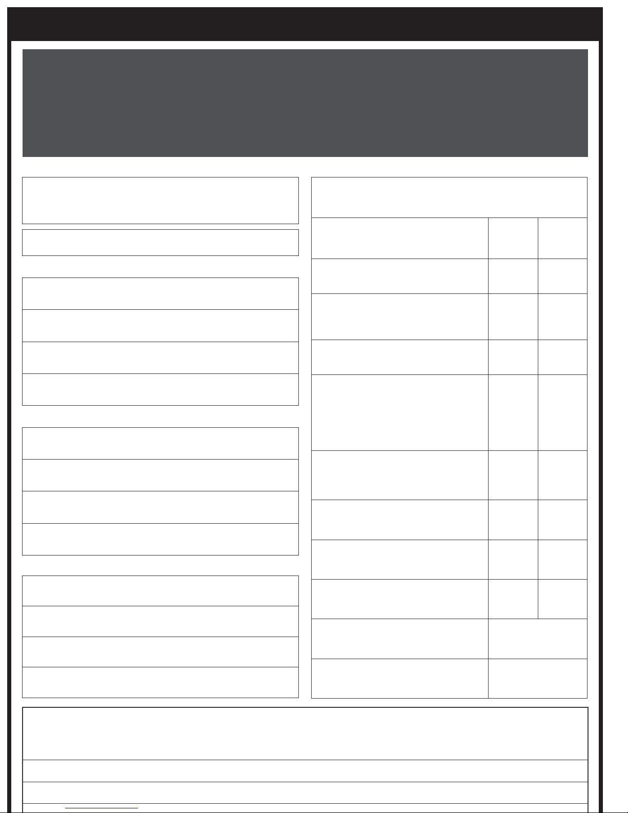
POST-INSTALLATION REPORT
POST-INSTALLATION REPORT
FOR TUNGSTEN SMART-HEAT GAS RADIANT HEATERS
AFTER HEATER INSTALLATION PLEASE PHOTOCOPY, COMPLETE, & SEND THIS REPORT BY:
FAX TO (02) 9748 4289 or BY MAIL TO Bromic Heating Pty Ltd, Suite 1305, 13223 Black Mountain Road
San Diego, California 92129 USA or SCAN AND EMAIL TO [email protected]
Customer Business Name:
Please fill in the relevant information or circle the
appropriate Yes/No responses below:
Date:
Site Address:
Suburb:
State: Postcode:
Customer Contact Details:
Name:
Position:
Ph: ( ) Fax: ( )
dd / mm / yyyy
How many Tungsten Smart-Heat
heaters are installed on this site?
What type of gas is used? Propane
Is/Are the heater(s) exposed to
salt air or any other corrosive or
chemical atmosphere?
Does the heater(s’) installation
location pose a hazard to the site?
Do heater clearances match the
minimum requirements outlined
in the “Installation Requirements”
section of the
Operation and Service Manual?
Is the gas supply line adequately
sized for the number of heaters
installed?
Have gas lines been purged of air? Yes No
Installation,
300:
________
Yes No
Yes No
Yes No
Yes No
500:
________
Natural
Gas
Mobile:
Installer Contact Details:
Name:
Position:
Ph: ( ) Fax: ( )
Mobile:
Signature of authorised person:
Name:
Company: Position:
Have gas lines been checked for
leaks with a soapy water solution?
Was the heater field tested and
operated without malfunction?
What is the inlet gas supply
pressure?
What is the gas valve outlet
pressure (at test point)?
Yes No
Yes No
_________ kPa
_________ kPa
Page 25
TROUBLESHOOTING
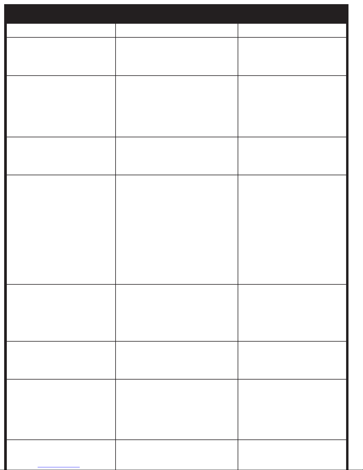
SYMPTOM POSSIBLE CAUSE CORRECTIVE ACTION
Heater will not turn on 1. No power
2. No gas
Heater turns on, but then cycles on
and off
No gas 1. Air in gas line
Low ceramic tile surface temperature 1. Low manifold gas pressure
1. Insufficient flame on ionisation rod
2. Drafty conditions
3. Insufficient earth connection between
heater and control box
2. Manual shut-off valve closed
3. Regulator sticking
4. Regulator reversed
2. Low gas inlet pressure
3. Orifice partially blocked with foreign
matter
4. Combustion by-products not
adequately ventilated
5. Manifold misaligned from excessive
torque applied on pipe at installation
6. Gas supply piping too small
7. Foreign matter in venturi tube
1. Have authorized electrician check
power supply
2. Have authorized gas fitter check
gas supply
1.
UÊCheck and set gas pressure
UÊCheck and clear obstruction to
burner venturi and injectors
2. Discontinue use in high winds
3. Replace wiring harness and clean
connections to ensure good
grounding
1. Purge line
2. Open valve
3. Replace regulator
4. Remove and install properly
1. Adjust valve regulator until 5”W.A
for natural gas, or 11” W.A for
propane is obtained
2. Adjust main supply regulator until
at least 6” W.C for natural gas or
11” W.C for propane precedes
heater’s control assembly
3. Clean orifice
4. Provide adequate ventilation of
by-products
5. Replace manifold
6. Increase gas pressure or replace
piping
7. Remove with bottle brush
Gas odour 1. Loose pipe connection
2. Defective regulator
3. Defective manual shut-off valve
4. Defective gas control valve
5. Loose flexible hose
Burning of gas/air mixture inside
burner casting (flashback)
Control assembly is overheating 1. Heater not mounted correctly 1. Mount wall bracket / control
Carbon formation on ceramic tile
surface of burner
1. Separation of ceramic tiles
2. Ceramic tile(s) cracked
3. Heater mounted at incorrect angle
4. Excessive drafts
1. Misaligned orifice
2. Obstruction in venturi tube
3. Low gas pressure
4. Wrong gas supplied to heater
1. Check all connections with soap
solution and tighten where
necessary
2. Replace regulator
3. Replace manual shut-off valve
4. Replace gas control valve
5. Tighten flexible hose
1. Replace burner assembly
2. Replace burner assembly
3. Check angle of heater. See heater
nameplate.
4. Shield or relocate heater.
housing against a vertical flat
surface, following the instructions
outlined in the installation section
of this manual. Always use
supplied parts to mount heater.
1. Consult sales agent or factory
2. Clean with bottle brush
3. Provide required pressure
4. Check label for type of gas
Page 26
APPENDIX A
Page 27
APPENDIX A CONTINUED...
 Loading...