

Page 1
!
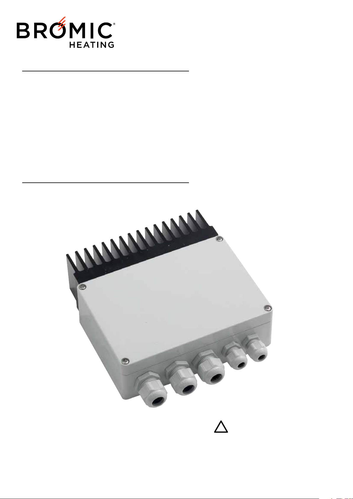
TUNGSTEN SMART-HEAT™
ELECTRIC WIRELESS DIMMER CONTROLLER
BY BROMIC
USER MANUAL
Version 1.0
Doc. T744.01_EN (TEMP)
TVHET916A07BK
IMPORTANT
READ THIS MANUAL CAREFULLY.
SEE INSIDE COVER FOR IMPORTANT
INFORMATION ABOUT THIS MANUAL. KEEP
INSTRUCTION WITH APPLIANCE FOR FUTURE
REFERENCE.
Page 2
!
IMPORTANT
!!!
This manual contains important information about the installation, and operation of Tungsten
Electric controller. Please pay close attention to the important safety information shown
throughout this instruction manual. Any safety information will be accompanied by the following
safety alert symbols:
DANGER, WARNING, IMPORTANT
• READ THIS MANUAL CAREFULLY before installing or
servicing this product.
• Improper installation or operation can result in death, severe
injury, or property damage.
• Use this controller only as described in this manual. Any other
use not recommended by the manufacturer may cause fire,
electric shock, or injury to persons
• This controller is intended for fixed installation with 110 - 277
volt power supply.
• Installation MUST be carried out by a licensed and authorised
technician in accordance with local electrical codes.
• For Commercial Use Only
NOTE: IMPORTANT INSTRUCTIONS, SAVE THESE
INSTRUCTIONS
WARNING
• The radio signal reception of the device can be affected by the presence of
electrical disturbances being transmitted by other appliances working on the same
frequency or if the product is shielded by metal parts.
• Do not use the remote in places where systems are sensitive to radio emissions.
• Do not keep or use the remote in places that are damp, where there is steam, high
air humidity, dust or where it is exposed to direct sunlight or similar environmental
conditions.
• Do not drop the remote. This could damage or reduce the range of action of the
remote.
• Do not use your nails to press remote buttons.
• Keep remote batteries out of reach of children.
• Call a doctor immediately if a battery is swallowed.
• See remote instruction manual for more details on the included remote.
BROMIC HEATING
Head Office: 10 Phiney Place, Ingleburn, NSW, 2565, Australia
Telephone: +61 2 9426 5222 Fax: +61 1300 735 115
Email: [email protected] Web: www.bromicheating.com
Note: Bromic Heating reserves the right to make changes to specifications, parts, components and equipment without prior notification.
This Installation, operation and service manual may not be reproduced in any form with prior written consent from Bromic Heating.
Manufactured by Teleco Automation s.r.l. - Italy - www.telecoautomation.com
2
www.bromicheating.com
Page 3

CONTENTS
IMPORTANT NOTES & WARNINGS 4
PRODUCT OVERVIEW 5
INSTALLATION & OPERATION 6
TECHNICAL SPECIFICATIONS 7
WIRING DIAGRAM 8
www.bromicheating.com
3
Page 4
IMPORTANT NOTES AND WARNINGS
!
WARNING
• Read all instructions before installing or using this heater
• Use this controller only as described in this manual. Any other
use not recommended by the manufacturer may cause fire,
electric shock, or injury to persons.
• Improper installation, adjustment, or alteration and failure to
follow the warnings and instructions in this manual could result in
severe personal injury, death or property damage.
• The manufacturer is not responsible for any damage that could
happen from improper use. The manufacturer emphasises that
this controller should be used in a responsible manner and that
all procedures, warnings, and safety instructions contained in this
booklet be followed strictly.
• The product must be fixed on surfaces which cannot be
damaged by the high temperature. It must be placed in a well
ventilated location. It cannot be hermetically closed. It must be
fixed vertically, with cable glands downward.
• The connection cables must be protected against any accidental
impacts, using proper pipes.
• This controller is not intended for use in bathrooms, laundry
areas and similar indoor locations. Never locate controller where
it may fall into a bathtub or other water container.
• Do not install the controller directly near a bathtub, shower or
swimming pool. Any switches or controls must not be within
reach of a person in the bathtub, shower or swimming pool.
• Extreme caution is necessary when any controller is used by or
near children or invalids and whenever the controller or heater is
left operating and unattended.
• This controller is not intended for use by persons (including
children) with reduced physical, sensory or mental capabilities, or
lack of experience and knowledge, unless they have been given
supervision or instruction concerning use of the appliance by a
person responsible for their safety.
• Keep packaging materials out of reach of children
• Children and adults should be alerted to the hazards of
electrocution and should stay away to avoid serious personal injury
• Children should be carefully supervised when they are in the area
of the controller.
• Do not attempt to alter the controller in any manner.
• Do not paint any surface of the controller.
• Do not touch the controller with wet hands at any time.
• Do not use or store flammable materials near this appliance.
• Do not spray aerosols or flammable materials in the vicinity of the
controller while it is in operation
• Never operate the controller in an explosive environment such as
areas where petrol or other flammable liquids or vapours are stored.
INSTALLATION
• IMPORTANT - Installation must be carried out by a licensed and
authorised person.
• The installer is to ensure that the requirements of the local
authority, local electrical installation code, municipal building
codes, and any other relevant statutory regulations are carried
out.
• After unpacking, make sure the controller shows no signs of
visible damage or tampering. If the controller appears damaged,
contact the place of purchase for assistance.
• Remove transit protection before use.
• This appliance must only be used on a 110 - 277 Volt AC Single
Phase electricity supply.
• This controller is NOT intended to be installed on recreational
vehicles and/or boats.
• Do not run cord under carpeting. Do not cover with throw rugs,
runners or the like arrange cord away from traffic area and
where it will not be tripped over
• A controller has hot and arcing or sparking parts inside. Do not
use it in areas where gasoline, paint or flammable liquids are
used or stored.
• This Installation and Operation manual should not be removed
from the site of installation. Installer should leave manual with
the customer for future reference.
• Any guard or other protective device removed for servicing
(conducted by an authorised person) must be replaced before
operating the controller.
• If the controller has not been used, or will not be used, for a
long period of time, disconnect power supply
• For the disconnection from the power line, use an all-pole
switch with contacts having a dimension of at least 3,5mm.
MAINTENANCE/ REPAIR
• Installation and repair must be carried out by a qualified &
licenced service person only. The controller should be inspected
before use and at least annually serviced & inspected by a
qualified & licenced service person.
• Do not perform maintenance until controller has been turned
off and power disconnected.
• Check for damage to the controller regularly. If damage to
the appliance is suspected, discontinue use immediately and
contact the supplier or qualified person to repair.
• If the supply cord is damaged, it must be replaced by an
authorised and licenced person in order to avoid a hazard.
• At the end of this product’s useful life, it must not be disposed
of as domestic waste, but must be taken to a collection
centre for waste electrical and electronic equipment. It is the
user’s responsibility to dispose of this appliance through the
appropriate channels at the end of its useful life. Failure to do
so may incur the penalties established by laws governing waste
disposal. Proper differential collection and the subsequent
recycling, processing and environmentally compatible
disposal of waste equipment avoids unnecessary damage to
the environment and possible related health risks, and also
promotes recycling of the materials used in the appliance. For
further information on waste collection and disposal, contact
your local waste disposal service, or the place of purchase
ELECTRICAL CONNECTIONS
• All connections must be rated for a single-phase 110 - 277VAC
power supply, with an earth connection.
• Arrange all the necessary safety devices and use only materials
that comply with standard electrical installations.
• Signal and power voltage wiring (110 - 277Vac) must be
separated one from the other.
• The protective device (ln = 32A) must protect the building from
overcurrents and short circuit
• A readily accesible disconnect device shall be incorporated in
the building installation wiring.
• The cable must have a section properly rated according to the
load connected and nominal temperature range up to 90°C.
4
www.bromicheating.com
Page 5
PRODUCT OVERVIEW
!
!
!
!
1 DESCRIPTION
The Wireless Dimmer is suitable for resistive and infrared heaters. The controller allows the power output of the heater
to be dimmed down for maximum comfort. The control can be used with 110 - 277VAC supply voltages.
1.1 FEATURES
Controls ONE 6800W heater at 277/240VAC (3080W at 110VAC) or Controls TWO 3400W heaters at 277/240 VAC (1540W at
110VAC).
Wireless control with dimming 0% - 100%.
Wired control capabilities
Configurable soft-start function for increased heater life.
1.2 KIT CONTENTS
Wireless dimmer enclosed in a protective box.
7-channel remote
2. INSTALLATION / SAFETY INFORMATION
Responsibility for determining suitability for use in any application / equipment lies solely on the purchaser. Suitability
for use in your application is determined by applicable standards such as UL, cUL and CE and the completed system
involving this component should be tested to those standards. Please consult with Local authorities and applicable
wiring standards for your application.
WARNING: Operate the Wireless control only when the connected heater is visible to the user.
WARNING: Isolate mains before installing. Use only on with a properly secured heater.
PLUG AND SUPPLY CORD: Use an appropriately rated plug and supply cord - check the power requirements of the
connected loads. Socket outlet used must be near the equipment.
2.1 INSTALLATION
Study the WIRING DIAGRAM at the end of this document before starting installation.
1. Open cover to the box.
2. Setup the DIP switch settings. Use the ‘DIP SWITCH FUNCTION’ section for guideline.
3. Wire in power and heater as per the wiring diagram.
4. Power on the wireless control.
5. Program the wireless control as per ‘OPERATION’ section.
6. Refit cover to the box.
2.2 OPERATION
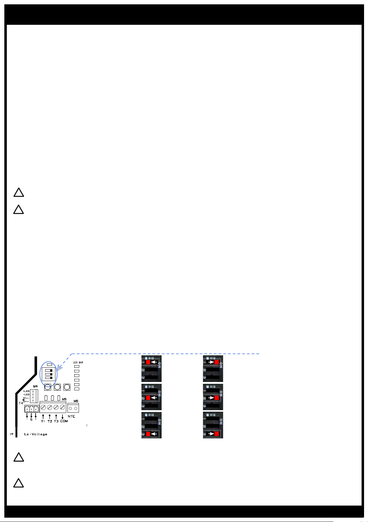
2.2.1 DIP switch function
Functioning time
(activated by PIR)
DIP1 = OFF
15 min
DIP1 = ON
30 min
PIR enabling
Configuration of
AREA
WARNING: FIRE HAZARD!! Even quality electronic components CAN FAIL, KEEPING FULL POWER ON! Provide a
SEPARATE (redundant) protective device where advisable and or required by local codes.
WARNING: HIGH VOLTAGE!! This controller is used to control HIGH VOLTAGES and must be installed in a GROUNDED
enclosure by a qualified electrician in accordance with applicable local and national codes including NEC and other
applicable codes.
the load type
DIP2 = OFF
OFF
DIP3 = OFF DIP3 = ON
Resistive Inductive
www.bromicheating.com
DIP2 = ON
ON
When Infrared Heater is selected and
a command is received, the device
activates the load with a “soft start”,
for extending the lifetime of the heater.
(infrared)
5
Page 6
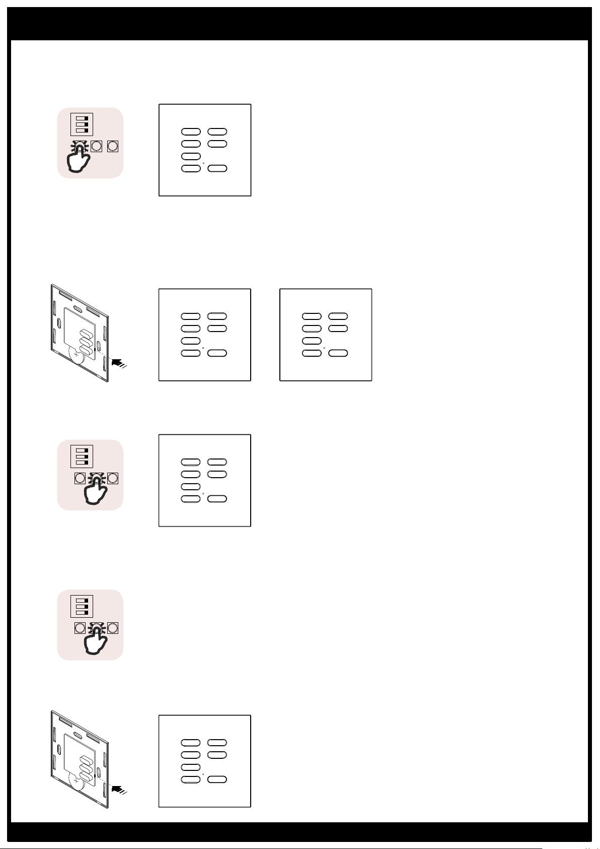
OPERATION
2.2.2 Programming of 7-channel remote
1. Press P1 once and hold down. A continuous beep will sound.
2. While holding the P1 button (during the continuous beep), press a push button on the 7-channel remote that is
going to be programmed. The programming is confirmed by an intermittent sound.
CH5
CH1
100%
CH2
P1
75%
50%
Min.
CH3
CH4
Once and hold
2.2.3 Copying a function of remote to a new remote. See remote manual for detail on P3 button.
1. Press the P3 button inside the already programmed remote. The active receiver will sound continuously.
2. Within 5 seconds, press a button of the already programmed remote. The sound will be interrupted, and continue
for another 5 seconds.
3. During the sound, press a button of the new remote that requires to be programmed. The programming is indicated
by an intermittent sound.
Memorised NewMemorised
CH1
100%
CH2
75%
CH3
50%
P3
Min.
CH4
CH6
CH7
CH5
CH6
CH7
DIM +
DIM -
OFF
DIM +
DIM -
OFF
All buttons are automatically
memorised with a preset
configuration as in the drawing.
CH5
CH1
100%
75%
50%
Min.
CH2
CH3
CH4
CH6
CH7
DIM +
DIM -
OFF
Attention: when a 7 channel
transmitter is copied, also its levels
will be copied into the new one.
2.2.4 Deleting a remote
1. Press the P2 button once and hold it down. There will be a slow and intermittent sound.
2. During the sound, press the button of the remote that will be deleted. The deletion is indicted by a continuous sound.
To be deleted
P2
100%
75%
50%
Min.
CH2
CH3
CH4
CH6
CH7
DIM +
DIM -
OFF
CH5
CH1
Once and hold
2.2.5 Deleting all remote
1. Press the P2 button two times and hold it down the second time until there will be a continuous sound after a quick and
intermittent sound.
2. Hearing the sound sequence above indicates that the whole memory of the receiver is deleted.
P2
Twice and hold
2.2.6 Deleting a remote from a remote. See remote manual for detail on P3 button.
1. Press the P3 button inside the remote. There will be slow and intermittent sound.
2. During the sound, press the button of the remote that will be deleted. The deletion is indicted by a continuous sound.
To be deletedMemorised
CH5
CH1
100%
CH2
75%
CH3
P3
50%
Min.
CH4
6
CH6
CH7
DIM +
DIM -
OFF
www.bromicheating.com
Page 7
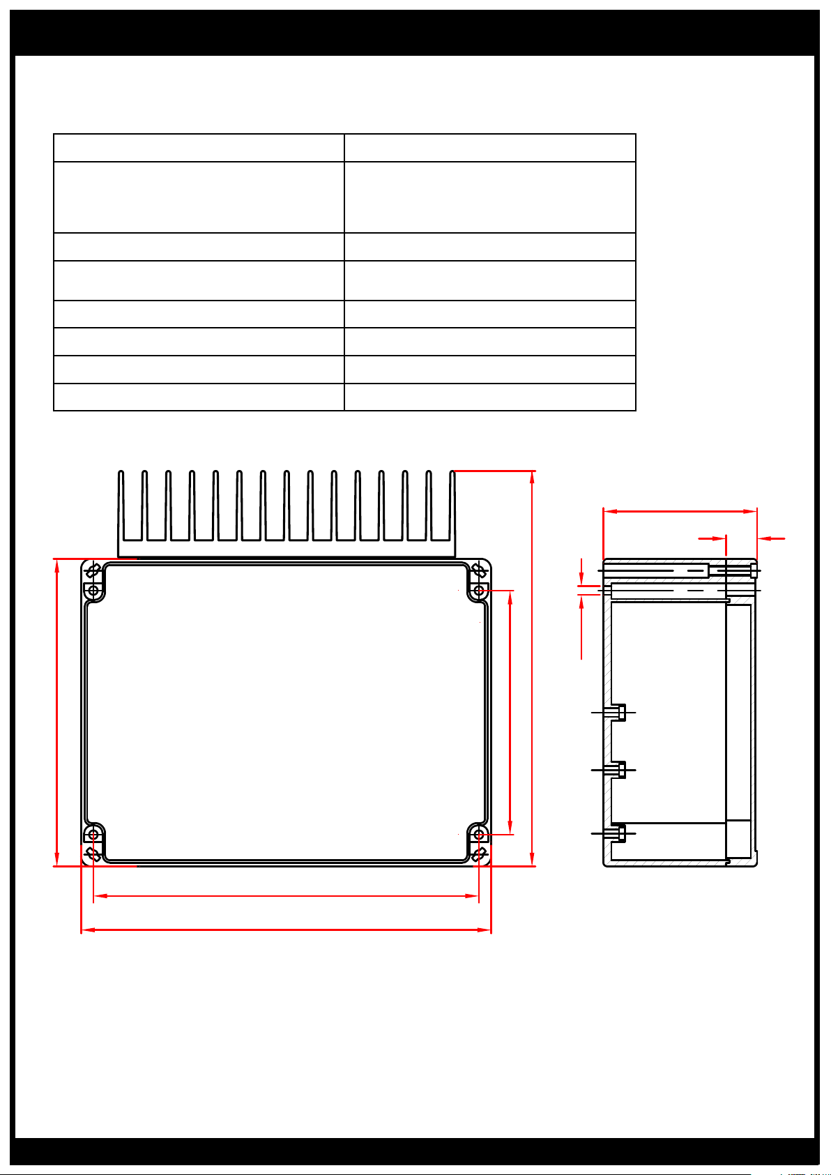
TECHNICAL SPECIFICATIONS
WIRELESS CONTROLLER
Power Supply 110/277VAC 50/60Hz (29A. max)
6800W @ 277VAC (25A.)
Max Output Power
Fuse Protection 32A (FWC high speed, 10 x 38mm)
6800W @ 240VAC (28,5A.)
3080W @ 110VAC (28A.)
Reception Frequency
Operating Temperature Range -20/+30°C
Maximum Remote Memorised 42
Dimensions 195 x 200 x 75mm
Protection Class IP54
916MHz (AUS/US)
868.3MHz (EU)
75
15
Ø4.2
150
227.5
119
188
200
Manufactured by Teleco Automation s.r.l. - Italy - www.telecoautomation.com
The manufacturer reserves the right to modify design features and technical data without notice.
www.bromicheating.com
7
Page 8
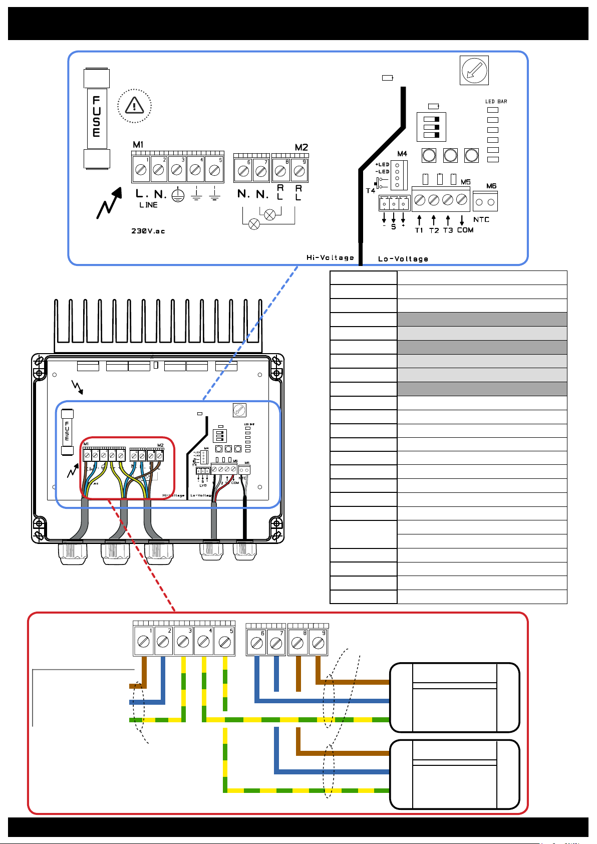
AREA
WIRING DIAGRAM
LED
ERROR
Do not operate in the high voltage area of
the electronic board, when it is supplied.
AREA
LED ERROR
L3
P1 P2 P3
TR1
DIP
SWITCH
AREA
1 POWER SUPPLY (LIVE)
2 POWER SUPPLY (NEUTRAL)
3 POWER SUPPLY (GROUND)
4 GROUND (OUTPUT ELEMENT 1)
5 GROUND (OUTPUT ELEMENT 2)
6 OUTPUT ELEMENT 1 (NEUTRAL)
7 OUTPUT ELEMENT 2 (NEUTRAL)
8 OUTPUT ELEMENT 2 (LIVE)
9 OUTPUT ELEMENT 1 (LIVE)
M5-T1 PUSHBUTTON INPUT (N.O.)
M5-T2 PIR INPUT (N.O.)
M5-COM INPUTS COMMON
NTC TEMPERATURE PROBE INPUT
M4-LED+ LED INDICATOR OUTPUT (+)
M4-LED- LED INDICATOR OUTPUT (-)
M4-T4 PUSHBUTTON INPUT (N.O.)
L1, L2 INPUT LED
L3 RADIO RECEIVER LED
ON = OVERLOAD
FLASHING = OVERHEATING
LED BAR OUTPUT LEVEL
TR1 TEMPERATURE ADJUSTMENT
P1-P3 PROGRAMMING BUTTONS
- S + EXTERNAL LEVEL VISUALIZER
HOT, BLACK (120V)* / L
HOT, RED (120V)* / N
Note: Neutral (N) is not required when
using split-phase 220-240V.
8
110-277Vac IN
GND
Section ≥ 4 mm
Section ≥ 1.5 mm
L
N
Gnd
L
N
Gnd
www.bromicheating.com
ELEMENT 1
≤ 1.5KW (110Vac)
≤ 3.4KW (240Vac)
≤ 3.4KW (277Vac)
ELEMENT 2
≤ 1.5KW (110Vac)
≤ 3.4KW (240Vac)
≤ 3.4KW (277Vac)
 Loading...