

Broilmaster Ssg-36-1 Owner's Manual
INSTALLATION INSTRUCTIONS
AND
The Superb SeriesThe Superb Series
The Superb Series
The Superb SeriesThe Superb Series
GRILL SHOWN WITH OPTIONAL SCG-36 CART
OWNER'S MANUAL
OUTDOOR
COOKING APPLIANCE
SSG-36-1
EFFECTIVE DATE
APRIL, 2003
FOR YOUR SAFETY
If you smell gas:
1. Shut off gas to the appliance.
2. Extinguish any open flame.
3. Open lid.
4. If odor continues, immediately call your
supplier or your fire department.
FOR YOUR SAFETY
1. Do not store or use gasoline or other flammable vapors and liquids in the vicinity of
this or any other appliance.
2. An LP cylinder not connected for use shall
not be stored in the vicinity of this or any
other appliance.
WARNING: If not installed, operated and
maintained in accordance with the manufacturer's instructions, this product could
expose you to substances in fuel or from fuel
combustion which can cause death or serious illness.
AVERTISSEMENT
S'il y a une odeur de gaz:
1. Coupez l'admission de gaz de l'appareil.
2. Éteindre toute flamme nue.
3. Ouvrir le couvercle.
4. Si l'odeur persiste, appeler immédiatement
votre compagnie de gaz ou votre département
des incendies.
AVERTISSEMENT
1. Ne pas entreposer ni utiliser de l'essence ni
d'autres vapeurs ou liquides inflammables
dans le voisinage de l'appareil, ni de tout
autre appareil.
2. Une bouteille de propane que n'est pas
recordée en vue de son utilisation, ne doit pas
être entreposée dans le voisinage de cet
appareil ou de tout autre appareil.
AVERTISSEMENT: Si l’installation, l’usage
et l'entretien de ce produit ne sont pas faits
selon les instructions du fabricant, ce produit
peut vous exposer à des matières contenues
dans le carburant ou provenant de la
combustion du carburant lesquelles peuvent
causer la mort ou de sérieuses maladies.
R-3848 Page 1

IMPOR TANT WARNINGS
For Outdoor Use Only.
If Stored Indoors,
Detach and Leave Cylinder Outdoors.
• Read instructions before lighting.
• Open lid during lighting.
• If ignition does not immediately take place, turn the burner valve
handles to OFF, wait 5 minutes, and repeat the lighting procedure.
• Minimum clearance from sides and back of unit to adjacent combustible construction below top of unit, 6 inches from sides and 12 inches
from back.
• Minimum horizontal clearance from sides and back of unit to adjacent
vertical combustible construction extending above top of unit, 6 inches
from sides and 12 inches from back.
• Do not locate this outdoor cooking gas appliance under overhead
unprotected combustible surfaces.
• WARNING: Electrical Grounding Instructions
This outdoor cooking gas appliance is equipped with a three-prong
(grounding) plug for your protection against shock hazard and should
be plugged directly into a properly grounded three-prong receptacle.
Do not cut or remove the grounding prong from this plug.
• Keep any electrical supply cord and the fuel supply hose away from
any heated surfaces.
• DO NOT put anything around the outdoor cooking appliance that will
obstruct the flow of combustion and ventilation air.
• DO keep the outdoor cooking gas appliance area clear and free from
combustible material, gasoline and other flammable vapors and liquids.
• Do make visual check of burner flames. Clean and replace damaged
parts.
• This outdoor cooking gas appliance is not intended to be installed in or
on recreational vehicles and/or boats.
• This outdoor cooking gas appliance shall be used only outdoors and
shall not be used in a building, garage or any other enclosed area.
Pour Utilisation à l'Extérieur Seulement.
Si l'Appareil est Entre posé à l'Intérieur,
Enlever les Bouteilles et les Laisser à l'Extérieur.
• Lire les instructions avant d'allumer l'appareil.
• Ouvrir le couvercle avant d'allumer l'appareil.
• Si l'appareil ne s'allume pas immédiatement, fermer le
robinet du brûleur, attendre 5 minutes puis procéder de
nouveau à l'allumage.
• Dégagement minimal à respecter entre les côtes et l'arrière
de l'appareil et une construction combustible adjacente
située au-dessous de la partie supérieure de l'appareil, soit 6
pouces des côtés et 12 pouces de l'arrière.
• Dégagement horizontal minimal à respecter entre les côtés
et l'arrière de l'appareil et une construction combustible
verticale adjacent dépassant la partie supérieure de
l'appareil, soit 6 pouces des côtés et 12 pouces de l'arrière.
• Il est interdit d'installer le présent appareil au-dessous des
surfaces combustibles non protégées.
• AVERTISSEMENT: Instruction Pour la Mise à la Terre
Électrique
Cet appareil est muni d'une fiche à trois broches (mise à la
terre) afin de vous protéger des chocs et doit être branché
directement dans une prise de courant à trois broches
adéquatement mise à la terre. Il ne faut pas couper ou
enlever la broche de mise à la terre de cette fiche.
PROPANE (LP) GAS WARNINGS
CUSTOMER WARNING:
• Know the odor of LP Gas. If you hear, see or smell leaking LP gas,
immediately get everyone away from the cylinder and call the Fire
Department. Do not attempt repairs.
• LP Gas is heavier than air and may settle in low places while
dissipating.
• Contact with the liquid contents of cylinder will cause freeze burns to
the skin.
• Do not allow children to tamper or play with cylinder.
• When not connected for use, keep cylinder valve turned off. Self
contained outdoor cooking appliances shall be limited to a cylinder of
20 lb. capacity or less.
• Do not use, store or transport cylinder where it would be exposed to
high temperatures. Relief valve may open allowing a large amount of
flammable gas to escape.
• When transporting, keep cylinder secured in an upright position with
cylinder valve turned off.
• CAUTION: The gas pressure regulator provided with this outdoor
cooking gas appliance must be used. This regulator is set for an outlet
pressure of 11 inches water column. (The outlet pressure specified by
the manufacturer.)
• The gas supply must be turned off at the LP gas supply cylinder when
this outdoor cooking gas appliance is not in use.
• The LP gas supply cylinder must be disconnected when this outdoor
cooking gas appliance is not in use.
AVERTISSEMENT:
• Savoir reconnaître l'odeur du GPL. Si vous entendez un sifflement
ou si vous sentez une fuite de GPL, demander immédiatement à
toutes les personnes présentes de s'éloigner de la boutielle et appeler
le service d'incendie. Ne pas essayer de la réparer.
• Le GPL étant plus lourd que l'air, il peut s'accumuler près du sol
avant de se dissiper.
• Tout contact de la peau avec la phase liquide de la bouteille causera
des brûlures par le froid.
• Empêcher les enfants de manipuler la bouteille ou de jouer avec.
• Lorsque la bouteille n'est pas raccordée à l'appareil, en maintenir
fermé le robinet. Pour les appareils de cuisson autonomes d'extérieur,
utiliser une bouteille d'une capacité maximale de 9 kg (20 lb.).
• Ne pas utiliser, entreposer ou transporter la bouteille en l'exposant à
une température excessive car la soupape de sûreté risque de s'ouvrir
et de laisser échapper une grande quantité de gaz inflammable.
• Pour transporter une bouteille de GPL, la maintenir solidement fixée
en position verticale avec le robinet fermé.
• MISE EN GARDE: Le régulateur de pression de gaz prévu avec
cet appareil de cuisson à gaz pour l'extérieur doit être utilisé. Ce
régulateur est réglé pour une pression de sortie de 11 pouces de
colonne d'eau (la pression de sortie spécifiée par le manufacturier.
• L'alimentation du gaz doit être fermée à la bouteille de gaz de
pétrole liquéfié, lorsque cet appareil de cuisson extérieur n'est
pas utilisé.
• La bouteille d'alimentation en gaz de pétrole liquéfié doit être
débranché lorsque cet appareil de cuisson extérieur n'est pas
utilisé.
Page 2 R-3848
SPECIFICATIONS
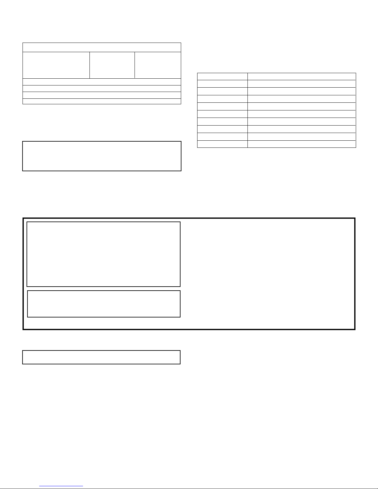
Specifications
Model SSG-36
Input BTU/HR (KW/H) Max. Min.
5 Main Burners 12,000/Burner 5,000
1 Side Burner 30,000 5,000
2 Rotisserie Burners 12,000/Burner
Height (grill only) 27 1/8"
Width 55 1/4"
Depth 31"
Gas Inlet 1/2"
General Information
This appliance is design certified in accordance with American National
Standards Institute Z21.58b-2002 and CGA-1.6b-2002 by the Canadian
Standards Association as an outdoor cooking gas appliance to be
installed according to these instructions.
Any alteration of the original design, installed other than as
shown in these instructions or use with a type of gas not shown
on the rating plate is the responsibility of the person and
company making the change.
Important
All correspondence should refer to complete Model number, Serial
number and type of gas.
Accessories
SCG-36 Stainless Steel Cart
GHK-12 Quick Disconnect 12 ft. Hose LP & Nat.
TKS-36 Stainless Steel Cooking Utensils
SGD-36 Stainless Steel Door for Built-in
GSS-36 Stainless Steel Side Shelf for Left or Right
GIJ-36 Stainless Steel Liner for Built-in
SUW-15 15" Stainless Steel Wok
VCC-36 Vinyl Cover for Grill on Cart
VCB-36 Vinyl Cover for Grill Built-in
SSP-1 Steamer Pan with Lid (1 Small & 1 Large)
Initial Operation
Before cooking food on your grill for the first time, operate the (5) main
burners at 500°F for 30 minutes. The high temperature will remove any
residues from the new components.
LP GAS CYLINDER INFORMATION
WARNING: Inspect the fuel supply hose before each use of
the outdoor cooking gas appliance. The hose can be accessed by opening the front door on the outdoor cooking gas
appliance. If it is evident there is excessive abrasion or
wear, or the hose is cut, it must be replaced prior to the
outdoor cooking gas appliance being put into operation.
Contact Empire Comfort Systems, Inc. to obtain a replacement fuel supply hose. Keep the ventilation opening(s) of
the cylinder enclosure free and clear from debris.
WARNING: Do not store a second 20 lb. propane cylinder
within the utility cart. The utility cart is designed for the use
and storage of one 20 lb. propane cylinder.
OVERFILL PROTECTION DEVICE (OPD) ON 20 LB. PROPANE
CYLINDER
Attention: Consumer be advised, this gas grill must be connected
to an LP gas cylinder incorporating an OPD.
The OPD will help reduce the potential for the overfilling of the propane
cylinder, thus reducing the possibility of hydrostatic relief valve discharges.
Overfill Protection Device Valve Function
1. As the cylinder is filled, the rising level of liquid propane lifts the
float to the stop position to prevent dangerous overfilling.
Does not affect the filling process or use of the cylinder.
2. At a safe filling level, the float cam triggers the pin to fall into the
recess of the cam, sealing this path off and preventing any more
liquid propane from flowing through the lower valve body into the
cylinder.
3. The propane builds up pressure in the chamber (center spring) and
pushes the piston up to form a seal, effectively stopping the filling
process.
• LP-gas supply cylinder to be used must be constructed and marked
in accordance with the specifications for LP-gas cylinders of the
U.S. Department of Transportation (DOT) or the National Standard
of Canada, CAN/CSA-B339, Cylinders, Spheres and Tubes for the
Transportation of Dangerous Goods.
If the outdoor cooking gas appliance is not in use, the gas must be
turned off at the supply cylinder.
• Storage of an outdoor cooking gas appliance indoors is permissible
only if the cylinder is disconnected and removed from the outdoor
cooking gas appliance.
Cylinders must be stored outdoors out of the reach of children and
must not be stored in a building, garage or any enclosed area.
• The pressure regulator and hose assembly supplied with the outdoor cooking gas appliance must be used. A replacement pressure
regulator and hose assembly for this outdoor cooking gas appliance
can be obtained by contacting Empire Comfort Systems, Inc.
4. The use of the propane from the cylinder allows the OPD to reset
itself for the next fill.
5. Connects to all standard or quick-connect couplings.
6. The Overfill Protection Device affects incoming liquid propane
flow only. Does not affect normal propane gas discharge when
properly connected to the appliance regulator.
7. All propane cylinders should be filled by qualified professionals
only.
Purging
1. Due to the decreased Btu delivery, purging may take longer.
2. To increase the speed of purging, open the outage valve during
release.
3. Reminder: Each new cylinder must be purged before filling.
4. For purging instructions, refer to NPGA 133-89(a).
Btu Delivery
The OPD valve has a size 56 orifice through which the propane is
released for consumption. Depending on the propane's temperature and
pressure, the release from the cylinder is approximately 125,000 Btu/
hour.
R-3848 Page 3
IMPORTANT INFORMATION ABOUT YOUR NEW TYPE-1
GRILL CONNECTION
Read all grill and related product literature before connecting or using
your grill, and please read the following information completely before
attempting to connect your grill to a propane cylinder.
Keep these instructions in a safe place. You may need to refer to them
when connecting other cylinders after filling.
Your new grill regulator is equipped with a coupling nut . Do not attempt
to connect any propane cylinder not equipped with a mating Type-1
cylinder valve.
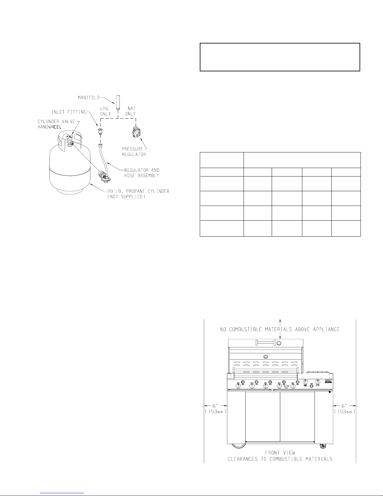
Figure 1
Connecting the Regulator to the Valve (Figure 1)
This Type-1 cylinder valve contains a backcheck which is designed to
prevent propane from flowing until the valve is properly connecting to
a regulator.
When connecting the regulator to the Type-1 cylinder valve, be sure
the pressure relief valve is directed away from the front of the grill and
away from any building. If the pressure relief valve should open, the
propane will then be directed where it is likely to do the least harm if
ignited.
WARNING: Do not insert any foreign objects into the valve
outlet. You may damage the backcheck. A damaged backcheck
can be the source of a leak. Leaking propane may result in
explosion, fire, personal injury or death.
Regulator Coupling Nut
The coupling nut connects to the large outside threads on the valve
outlet. To complete the connection, follow the steps below.
1. Be sure all grill burner knobs, side burner knob and rotisserie
burner knob are in the OFF position.
2. Make sure the cylinder valve handwheel is in the closed position.
Turn clockwise (left to right) to a full stop.
3. Remove the protective caps from the cylinder valve and coupling
nut.
4. Turn the coupling nut clockwise (left to right), to tighten to a full
stop. Be sure the coupling nut is not cross-threaded.
Recommended Gas Pipe Diameter
Pipe Length Schedule 40 Pipe Tubing, Type L
(Feet) Inside Diameter Outside Diameter
Nat. L.P. Nat. L.P.
0-10 1/2" 3/8" 1/2" 3/8"
1.3 cm 1.0 cm 1.3 cm 1.0 cm
10-40 1/2" 1/2" 5/8" 1/2"
1.3 cm 1.3 cm 1.6 cm 1.3 cm
40-100 1/2" 1/2" 3/4" 1/2"
1.3 cm 1.3 cm 1.9 cm 1.3 cm
100-150 3/4" 1/2" 7/8" 3/4"
1.9 cm 1.3 cm 2.2 cm 1.9 cm
Note: Never use plastic pipe. Check to confirm whether your local codes
allow copper tubing or galvanized.
INSTALLING AND LOCATING YOUR GRILL
The installation must conform with local codes or, in the absence of local
codes, with the National Fuel Gas Code ANSI Z223.1*/ Canadian
Installation Code, CAN/CGA-B149.
*Available from the American National Standards Institute, Inc., 11
West 42nd St., New York, NY 10036.
Qualified Installing Agency
Installation and replacement of gas piping, gas utilization equipment or
accessories and repair and servicing of equipment shall be performed
only by a qualified agency. The term "qualified agency" means any
individual, firm, corporation or company which whether in person or
through a representative is engaged in and is responsible for (a) the
installation or replacement of gas piping or (b) the connection, installation, repair or servicing of equipment, who is experienced in such work,
familiar with all precautions required and has complied with all the
requirements of the authority having jurisdiction.
Instruction to Installer
1. Installer must leave instruction manual with owner after installation.
2. The owner shall retain this instruction manual for future reference.
3. Installer must have owner fill out and mail warranty card supplied
with appliance.
4. Installer should show owner how to start and operate gas grill.
LOCATION REQUIREMENTS
Location (Figure 2 and Figure 3)
When determining a suitable location take into account concerns such
as exposure to wind, proximity to traffic paths and keeping any gas
supply lines as short as possible. Locate the grill only in well ventilated
area. Never locate the grill in a building, garage, breezeway, shed or
other such enclosed areas. During heavy use the grill will produce a lot
of smoke. Ensure that there is adequate area for smoke to dissipate.
• Minimum clearance from sides and back of unit to adjacent combustible construction below top of unit, 6 inches from sides and 12 inches
from back.
• Minimum horizontal clearance from sides and back of unit to adjacent
vertical combustible construction extending above top of unit, 6
inches from sides and 12 inches from back.
Figure 2
Page 4 R-3848
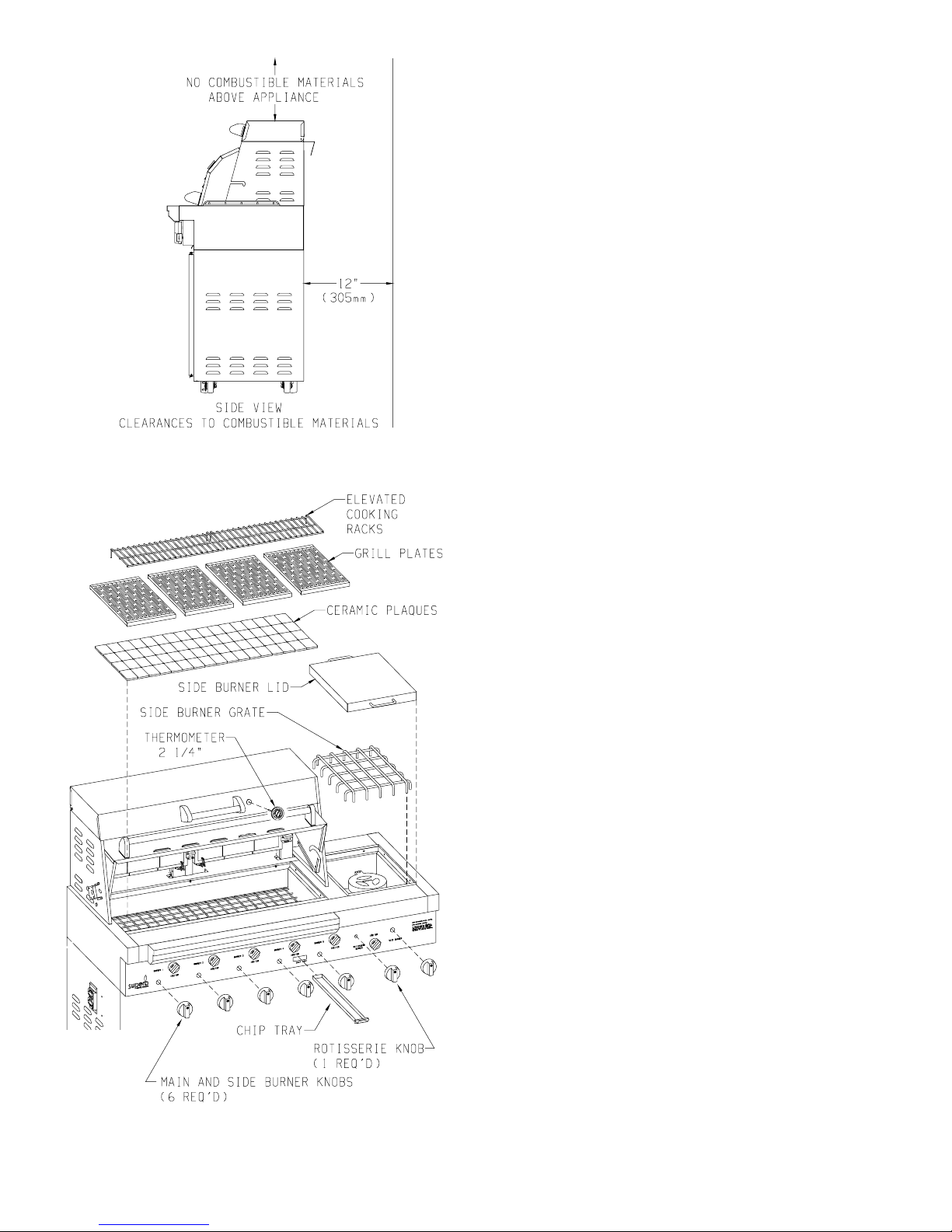
Figure 3
Figure 4
The cardboard box within your grill contains the following parts:
(Figure 4)
1 box of ceramic plaques (70)
4 grill plates
1 grill plate handle (see page 14, part number 19)
2 elevated cooking racks
1 side burner grate
1 side burner lid
6 burner knobs
1 rotisserie knob
1 chip tray
1 - 5" thermometer for front lid
1 - 2 1/4" thermometer for steamer lid
1 inlet adaptor (LP gas grill only)
1 hose assembly with LP regulator (LP gas grill only)
1 Natural gas regulator (Natural gas grill only)
1 rotisserie rod
1 rotisserie handle
1 counter balance
4 meat forks
1 rotisserie motor
2 rotisserie drip pans
Sequence of Installation of Grill Parts
1. Lay ceramic plaques onto the plaque rack.
2. Place 4 grill plates into grill (flat side or sear side). Your grill plate
handle is used to flip the grill plates to flat side or sear side.
3. Install 2 elevated cooking racks above rotisserie burners.
4. Place side burner grate over side burner.
5. Place side burner lid over side burner grate.
6. Snap 6 burner knobs onto 5 main burner valve stems and onto side
burner valve stem. The inside of a burner knob has a mushroom
pattern.
7. Snap 1 rotisserie burner knob onto rotisserie burner valve stem. The
inside of the rotisserie burner knob has a 3/4 round pattern.
8. Insert chip tray into grill front between the fourth and fifth main
burner knobs.
9. Insert 5" thermometer into grill lid.
10. Insert 2 1/4" thermometer into steamer lid.
11. For LP gas only, thread brass inlet adaptor onto manifold pipe. Use
teflon tape or a LP gas pipe compound to make a gas tight connection
(see Figure 1).
12. For LP gas only, thread brass fitting from hose assembly onto brass
inlet adaptor (see Figure 1). Tighten completely for a gas tight
connection.
13. For Natural gas only, thread Natural gas regulator onto manifold
pipe. Use teflon tape or a Natural gas pipe compound to make a gas
tight connection (see Figure 1).
14. Refer to Rotisserie section, page 9 for installation of rotisserie parts
(see Figure 8).
LEAK TESTING
1. Before lighting your grill, check all connections for leaks using
a mild soapy water solution. DO NOT use matches, lighters or
flame to check for leaks, — you could cause an explosion. With
the grill burner controls turned OFF, slowly open the cylinder
valve by turning the handwheel counterclockwise (right to left).
Apply mild soapy water to the connection. If bubbles appear,
a leak is indicated. Do not put the product in service! Immediately
close the cylinder valve handwheel for propane gas or the manual
shutoff valve for natural gas. A qualified service person must be
contacted to make the needed repairs.
2. DO NOT SMOKE WHILE LEAK TESTING!
3. For LP gas (propane) models, leak test with a full propane cylinder.
R-3848 Page 5
 Loading...