

Page 1
INSTALLATION INSTRUCTIONS
AND
The Superb SeriesThe Superb Series
The Superb Series
The Superb SeriesThe Superb Series
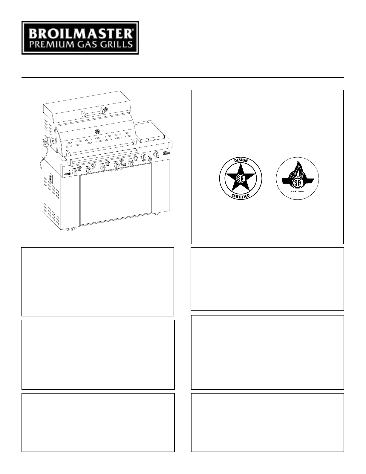
GRILL SHOWN WITH OPTIONAL SCG-36 CART
OWNER'S MANUAL
OUTDOOR
COOKING APPLIANCE
SSG-36-1
EFFECTIVE DATE
APRIL, 2003
FOR YOUR SAFETY
If you smell gas:
1. Shut off gas to the appliance.
2. Extinguish any open flame.
3. Open lid.
4. If odor continues, immediately call your
supplier or your fire department.
FOR YOUR SAFETY
1. Do not store or use gasoline or other flammable vapors and liquids in the vicinity of
this or any other appliance.
2. An LP cylinder not connected for use shall
not be stored in the vicinity of this or any
other appliance.
WARNING: If not installed, operated and
maintained in accordance with the manufacturer's instructions, this product could
expose you to substances in fuel or from fuel
combustion which can cause death or serious illness.
AVERTISSEMENT
S'il y a une odeur de gaz:
1. Coupez l'admission de gaz de l'appareil.
2. Éteindre toute flamme nue.
3. Ouvrir le couvercle.
4. Si l'odeur persiste, appeler immédiatement
votre compagnie de gaz ou votre département
des incendies.
AVERTISSEMENT
1. Ne pas entreposer ni utiliser de l'essence ni
d'autres vapeurs ou liquides inflammables
dans le voisinage de l'appareil, ni de tout
autre appareil.
2. Une bouteille de propane que n'est pas
recordée en vue de son utilisation, ne doit pas
être entreposée dans le voisinage de cet
appareil ou de tout autre appareil.
AVERTISSEMENT: Si l’installation, l’usage
et l'entretien de ce produit ne sont pas faits
selon les instructions du fabricant, ce produit
peut vous exposer à des matières contenues
dans le carburant ou provenant de la
combustion du carburant lesquelles peuvent
causer la mort ou de sérieuses maladies.
R-3848 Page 1
Page 2

IMPOR TANT WARNINGS
For Outdoor Use Only.
If Stored Indoors,
Detach and Leave Cylinder Outdoors.
• Read instructions before lighting.
• Open lid during lighting.
• If ignition does not immediately take place, turn the burner valve
handles to OFF, wait 5 minutes, and repeat the lighting procedure.
• Minimum clearance from sides and back of unit to adjacent combustible construction below top of unit, 6 inches from sides and 12 inches
from back.
• Minimum horizontal clearance from sides and back of unit to adjacent
vertical combustible construction extending above top of unit, 6 inches
from sides and 12 inches from back.
• Do not locate this outdoor cooking gas appliance under overhead
unprotected combustible surfaces.
• WARNING: Electrical Grounding Instructions
This outdoor cooking gas appliance is equipped with a three-prong
(grounding) plug for your protection against shock hazard and should
be plugged directly into a properly grounded three-prong receptacle.
Do not cut or remove the grounding prong from this plug.
• Keep any electrical supply cord and the fuel supply hose away from
any heated surfaces.
• DO NOT put anything around the outdoor cooking appliance that will
obstruct the flow of combustion and ventilation air.
• DO keep the outdoor cooking gas appliance area clear and free from
combustible material, gasoline and other flammable vapors and liquids.
• Do make visual check of burner flames. Clean and replace damaged
parts.
• This outdoor cooking gas appliance is not intended to be installed in or
on recreational vehicles and/or boats.
• This outdoor cooking gas appliance shall be used only outdoors and
shall not be used in a building, garage or any other enclosed area.
Pour Utilisation à l'Extérieur Seulement.
Si l'Appareil est Entre posé à l'Intérieur,
Enlever les Bouteilles et les Laisser à l'Extérieur.
• Lire les instructions avant d'allumer l'appareil.
• Ouvrir le couvercle avant d'allumer l'appareil.
• Si l'appareil ne s'allume pas immédiatement, fermer le
robinet du brûleur, attendre 5 minutes puis procéder de
nouveau à l'allumage.
• Dégagement minimal à respecter entre les côtes et l'arrière
de l'appareil et une construction combustible adjacente
située au-dessous de la partie supérieure de l'appareil, soit 6
pouces des côtés et 12 pouces de l'arrière.
• Dégagement horizontal minimal à respecter entre les côtés
et l'arrière de l'appareil et une construction combustible
verticale adjacent dépassant la partie supérieure de
l'appareil, soit 6 pouces des côtés et 12 pouces de l'arrière.
• Il est interdit d'installer le présent appareil au-dessous des
surfaces combustibles non protégées.
• AVERTISSEMENT: Instruction Pour la Mise à la Terre
Électrique
Cet appareil est muni d'une fiche à trois broches (mise à la
terre) afin de vous protéger des chocs et doit être branché
directement dans une prise de courant à trois broches
adéquatement mise à la terre. Il ne faut pas couper ou
enlever la broche de mise à la terre de cette fiche.
PROPANE (LP) GAS WARNINGS
CUSTOMER WARNING:
• Know the odor of LP Gas. If you hear, see or smell leaking LP gas,
immediately get everyone away from the cylinder and call the Fire
Department. Do not attempt repairs.
• LP Gas is heavier than air and may settle in low places while
dissipating.
• Contact with the liquid contents of cylinder will cause freeze burns to
the skin.
• Do not allow children to tamper or play with cylinder.
• When not connected for use, keep cylinder valve turned off. Self
contained outdoor cooking appliances shall be limited to a cylinder of
20 lb. capacity or less.
• Do not use, store or transport cylinder where it would be exposed to
high temperatures. Relief valve may open allowing a large amount of
flammable gas to escape.
• When transporting, keep cylinder secured in an upright position with
cylinder valve turned off.
• CAUTION: The gas pressure regulator provided with this outdoor
cooking gas appliance must be used. This regulator is set for an outlet
pressure of 11 inches water column. (The outlet pressure specified by
the manufacturer.)
• The gas supply must be turned off at the LP gas supply cylinder when
this outdoor cooking gas appliance is not in use.
• The LP gas supply cylinder must be disconnected when this outdoor
cooking gas appliance is not in use.
AVERTISSEMENT:
• Savoir reconnaître l'odeur du GPL. Si vous entendez un sifflement
ou si vous sentez une fuite de GPL, demander immédiatement à
toutes les personnes présentes de s'éloigner de la boutielle et appeler
le service d'incendie. Ne pas essayer de la réparer.
• Le GPL étant plus lourd que l'air, il peut s'accumuler près du sol
avant de se dissiper.
• Tout contact de la peau avec la phase liquide de la bouteille causera
des brûlures par le froid.
• Empêcher les enfants de manipuler la bouteille ou de jouer avec.
• Lorsque la bouteille n'est pas raccordée à l'appareil, en maintenir
fermé le robinet. Pour les appareils de cuisson autonomes d'extérieur,
utiliser une bouteille d'une capacité maximale de 9 kg (20 lb.).
• Ne pas utiliser, entreposer ou transporter la bouteille en l'exposant à
une température excessive car la soupape de sûreté risque de s'ouvrir
et de laisser échapper une grande quantité de gaz inflammable.
• Pour transporter une bouteille de GPL, la maintenir solidement fixée
en position verticale avec le robinet fermé.
• MISE EN GARDE: Le régulateur de pression de gaz prévu avec
cet appareil de cuisson à gaz pour l'extérieur doit être utilisé. Ce
régulateur est réglé pour une pression de sortie de 11 pouces de
colonne d'eau (la pression de sortie spécifiée par le manufacturier.
• L'alimentation du gaz doit être fermée à la bouteille de gaz de
pétrole liquéfié, lorsque cet appareil de cuisson extérieur n'est
pas utilisé.
• La bouteille d'alimentation en gaz de pétrole liquéfié doit être
débranché lorsque cet appareil de cuisson extérieur n'est pas
utilisé.
Page 2 R-3848
Page 3
SPECIFICATIONS
Specifications
Model SSG-36
Input BTU/HR (KW/H) Max. Min.
5 Main Burners 12,000/Burner 5,000
1 Side Burner 30,000 5,000
2 Rotisserie Burners 12,000/Burner
Height (grill only) 27 1/8"
Width 55 1/4"
Depth 31"
Gas Inlet 1/2"
General Information
This appliance is design certified in accordance with American National
Standards Institute Z21.58b-2002 and CGA-1.6b-2002 by the Canadian
Standards Association as an outdoor cooking gas appliance to be
installed according to these instructions.
Any alteration of the original design, installed other than as
shown in these instructions or use with a type of gas not shown
on the rating plate is the responsibility of the person and
company making the change.
Important
All correspondence should refer to complete Model number, Serial
number and type of gas.
Accessories
SCG-36 Stainless Steel Cart
GHK-12 Quick Disconnect 12 ft. Hose LP & Nat.
TKS-36 Stainless Steel Cooking Utensils
SGD-36 Stainless Steel Door for Built-in
GSS-36 Stainless Steel Side Shelf for Left or Right
GIJ-36 Stainless Steel Liner for Built-in
SUW-15 15" Stainless Steel Wok
VCC-36 Vinyl Cover for Grill on Cart
VCB-36 Vinyl Cover for Grill Built-in
SSP-1 Steamer Pan with Lid (1 Small & 1 Large)
Initial Operation
Before cooking food on your grill for the first time, operate the (5) main
burners at 500°F for 30 minutes. The high temperature will remove any
residues from the new components.
LP GAS CYLINDER INFORMATION
WARNING: Inspect the fuel supply hose before each use of
the outdoor cooking gas appliance. The hose can be accessed by opening the front door on the outdoor cooking gas
appliance. If it is evident there is excessive abrasion or
wear, or the hose is cut, it must be replaced prior to the
outdoor cooking gas appliance being put into operation.
Contact Empire Comfort Systems, Inc. to obtain a replacement fuel supply hose. Keep the ventilation opening(s) of
the cylinder enclosure free and clear from debris.
WARNING: Do not store a second 20 lb. propane cylinder
within the utility cart. The utility cart is designed for the use
and storage of one 20 lb. propane cylinder.
OVERFILL PROTECTION DEVICE (OPD) ON 20 LB. PROPANE
CYLINDER
Attention: Consumer be advised, this gas grill must be connected
to an LP gas cylinder incorporating an OPD.
The OPD will help reduce the potential for the overfilling of the propane
cylinder, thus reducing the possibility of hydrostatic relief valve discharges.
Overfill Protection Device Valve Function
1. As the cylinder is filled, the rising level of liquid propane lifts the
float to the stop position to prevent dangerous overfilling.
Does not affect the filling process or use of the cylinder.
2. At a safe filling level, the float cam triggers the pin to fall into the
recess of the cam, sealing this path off and preventing any more
liquid propane from flowing through the lower valve body into the
cylinder.
3. The propane builds up pressure in the chamber (center spring) and
pushes the piston up to form a seal, effectively stopping the filling
process.
• LP-gas supply cylinder to be used must be constructed and marked
in accordance with the specifications for LP-gas cylinders of the
U.S. Department of Transportation (DOT) or the National Standard
of Canada, CAN/CSA-B339, Cylinders, Spheres and Tubes for the
Transportation of Dangerous Goods.
If the outdoor cooking gas appliance is not in use, the gas must be
turned off at the supply cylinder.
• Storage of an outdoor cooking gas appliance indoors is permissible
only if the cylinder is disconnected and removed from the outdoor
cooking gas appliance.
Cylinders must be stored outdoors out of the reach of children and
must not be stored in a building, garage or any enclosed area.
• The pressure regulator and hose assembly supplied with the outdoor cooking gas appliance must be used. A replacement pressure
regulator and hose assembly for this outdoor cooking gas appliance
can be obtained by contacting Empire Comfort Systems, Inc.
4. The use of the propane from the cylinder allows the OPD to reset
itself for the next fill.
5. Connects to all standard or quick-connect couplings.
6. The Overfill Protection Device affects incoming liquid propane
flow only. Does not affect normal propane gas discharge when
properly connected to the appliance regulator.
7. All propane cylinders should be filled by qualified professionals
only.
Purging
1. Due to the decreased Btu delivery, purging may take longer.
2. To increase the speed of purging, open the outage valve during
release.
3. Reminder: Each new cylinder must be purged before filling.
4. For purging instructions, refer to NPGA 133-89(a).
Btu Delivery
The OPD valve has a size 56 orifice through which the propane is
released for consumption. Depending on the propane's temperature and
pressure, the release from the cylinder is approximately 125,000 Btu/
hour.
R-3848 Page 3
Page 4
IMPORTANT INFORMATION ABOUT YOUR NEW TYPE-1
GRILL CONNECTION
Read all grill and related product literature before connecting or using
your grill, and please read the following information completely before
attempting to connect your grill to a propane cylinder.
Keep these instructions in a safe place. You may need to refer to them
when connecting other cylinders after filling.
Your new grill regulator is equipped with a coupling nut . Do not attempt
to connect any propane cylinder not equipped with a mating Type-1
cylinder valve.
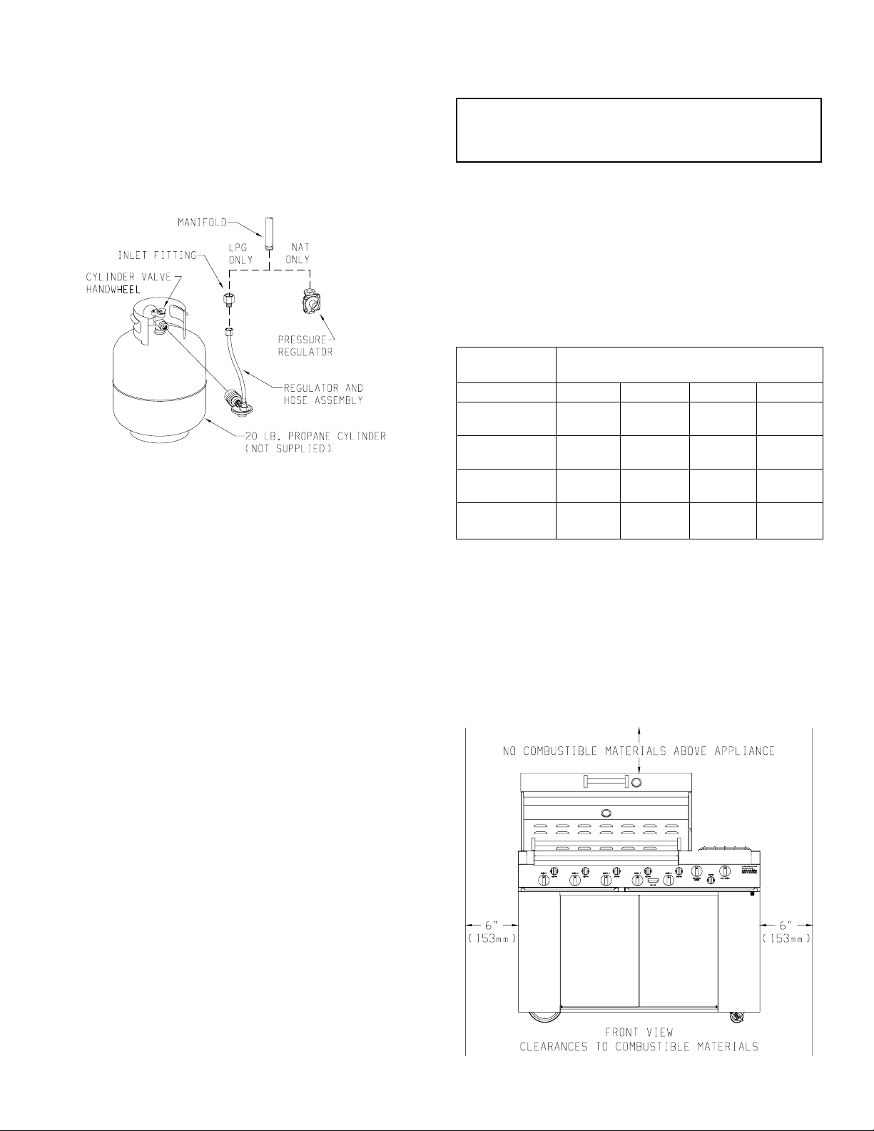
Figure 1
Connecting the Regulator to the Valve (Figure 1)
This Type-1 cylinder valve contains a backcheck which is designed to
prevent propane from flowing until the valve is properly connecting to
a regulator.
When connecting the regulator to the Type-1 cylinder valve, be sure
the pressure relief valve is directed away from the front of the grill and
away from any building. If the pressure relief valve should open, the
propane will then be directed where it is likely to do the least harm if
ignited.
WARNING: Do not insert any foreign objects into the valve
outlet. You may damage the backcheck. A damaged backcheck
can be the source of a leak. Leaking propane may result in
explosion, fire, personal injury or death.
Regulator Coupling Nut
The coupling nut connects to the large outside threads on the valve
outlet. To complete the connection, follow the steps below.
1. Be sure all grill burner knobs, side burner knob and rotisserie
burner knob are in the OFF position.
2. Make sure the cylinder valve handwheel is in the closed position.
Turn clockwise (left to right) to a full stop.
3. Remove the protective caps from the cylinder valve and coupling
nut.
4. Turn the coupling nut clockwise (left to right), to tighten to a full
stop. Be sure the coupling nut is not cross-threaded.
Recommended Gas Pipe Diameter
Pipe Length Schedule 40 Pipe Tubing, Type L
(Feet) Inside Diameter Outside Diameter
Nat. L.P. Nat. L.P.
0-10 1/2" 3/8" 1/2" 3/8"
1.3 cm 1.0 cm 1.3 cm 1.0 cm
10-40 1/2" 1/2" 5/8" 1/2"
1.3 cm 1.3 cm 1.6 cm 1.3 cm
40-100 1/2" 1/2" 3/4" 1/2"
1.3 cm 1.3 cm 1.9 cm 1.3 cm
100-150 3/4" 1/2" 7/8" 3/4"
1.9 cm 1.3 cm 2.2 cm 1.9 cm
Note: Never use plastic pipe. Check to confirm whether your local codes
allow copper tubing or galvanized.
INSTALLING AND LOCATING YOUR GRILL
The installation must conform with local codes or, in the absence of local
codes, with the National Fuel Gas Code ANSI Z223.1*/ Canadian
Installation Code, CAN/CGA-B149.
*Available from the American National Standards Institute, Inc., 11
West 42nd St., New York, NY 10036.
Qualified Installing Agency
Installation and replacement of gas piping, gas utilization equipment or
accessories and repair and servicing of equipment shall be performed
only by a qualified agency. The term "qualified agency" means any
individual, firm, corporation or company which whether in person or
through a representative is engaged in and is responsible for (a) the
installation or replacement of gas piping or (b) the connection, installation, repair or servicing of equipment, who is experienced in such work,
familiar with all precautions required and has complied with all the
requirements of the authority having jurisdiction.
Instruction to Installer
1. Installer must leave instruction manual with owner after installation.
2. The owner shall retain this instruction manual for future reference.
3. Installer must have owner fill out and mail warranty card supplied
with appliance.
4. Installer should show owner how to start and operate gas grill.
LOCATION REQUIREMENTS
Location (Figure 2 and Figure 3)
When determining a suitable location take into account concerns such
as exposure to wind, proximity to traffic paths and keeping any gas
supply lines as short as possible. Locate the grill only in well ventilated
area. Never locate the grill in a building, garage, breezeway, shed or
other such enclosed areas. During heavy use the grill will produce a lot
of smoke. Ensure that there is adequate area for smoke to dissipate.
• Minimum clearance from sides and back of unit to adjacent combustible construction below top of unit, 6 inches from sides and 12 inches
from back.
• Minimum horizontal clearance from sides and back of unit to adjacent
vertical combustible construction extending above top of unit, 6
inches from sides and 12 inches from back.
Figure 2
Page 4 R-3848
Page 5
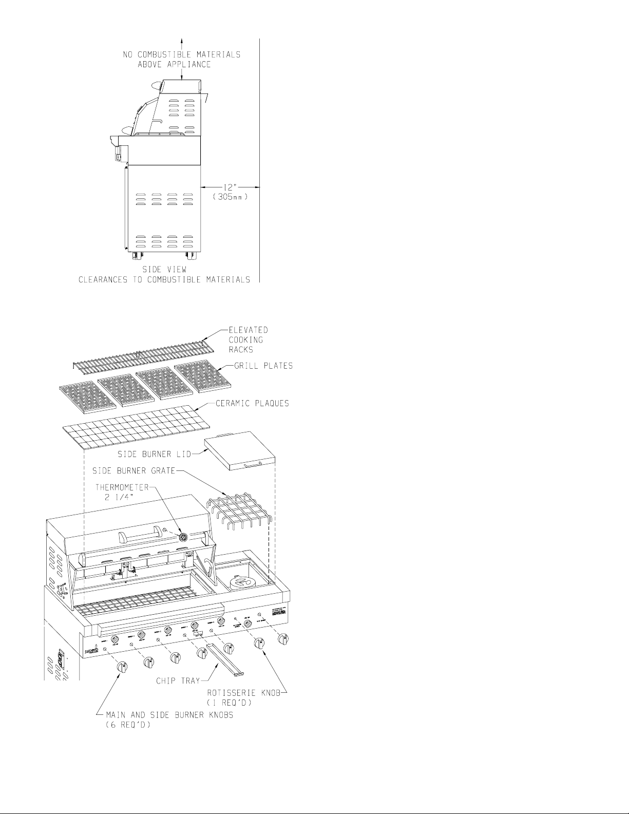
Figure 3
Figure 4
The cardboard box within your grill contains the following parts:
(Figure 4)
1 box of ceramic plaques (70)
4 grill plates
1 grill plate handle (see page 14, part number 19)
2 elevated cooking racks
1 side burner grate
1 side burner lid
6 burner knobs
1 rotisserie knob
1 chip tray
1 - 5" thermometer for front lid
1 - 2 1/4" thermometer for steamer lid
1 inlet adaptor (LP gas grill only)
1 hose assembly with LP regulator (LP gas grill only)
1 Natural gas regulator (Natural gas grill only)
1 rotisserie rod
1 rotisserie handle
1 counter balance
4 meat forks
1 rotisserie motor
2 rotisserie drip pans
Sequence of Installation of Grill Parts
1. Lay ceramic plaques onto the plaque rack.
2. Place 4 grill plates into grill (flat side or sear side). Your grill plate
handle is used to flip the grill plates to flat side or sear side.
3. Install 2 elevated cooking racks above rotisserie burners.
4. Place side burner grate over side burner.
5. Place side burner lid over side burner grate.
6. Snap 6 burner knobs onto 5 main burner valve stems and onto side
burner valve stem. The inside of a burner knob has a mushroom
pattern.
7. Snap 1 rotisserie burner knob onto rotisserie burner valve stem. The
inside of the rotisserie burner knob has a 3/4 round pattern.
8. Insert chip tray into grill front between the fourth and fifth main
burner knobs.
9. Insert 5" thermometer into grill lid.
10. Insert 2 1/4" thermometer into steamer lid.
11. For LP gas only, thread brass inlet adaptor onto manifold pipe. Use
teflon tape or a LP gas pipe compound to make a gas tight connection
(see Figure 1).
12. For LP gas only, thread brass fitting from hose assembly onto brass
inlet adaptor (see Figure 1). Tighten completely for a gas tight
connection.
13. For Natural gas only, thread Natural gas regulator onto manifold
pipe. Use teflon tape or a Natural gas pipe compound to make a gas
tight connection (see Figure 1).
14. Refer to Rotisserie section, page 9 for installation of rotisserie parts
(see Figure 8).
LEAK TESTING
1. Before lighting your grill, check all connections for leaks using
a mild soapy water solution. DO NOT use matches, lighters or
flame to check for leaks, — you could cause an explosion. With
the grill burner controls turned OFF, slowly open the cylinder
valve by turning the handwheel counterclockwise (right to left).
Apply mild soapy water to the connection. If bubbles appear,
a leak is indicated. Do not put the product in service! Immediately
close the cylinder valve handwheel for propane gas or the manual
shutoff valve for natural gas. A qualified service person must be
contacted to make the needed repairs.
2. DO NOT SMOKE WHILE LEAK TESTING!
3. For LP gas (propane) models, leak test with a full propane cylinder.
R-3848 Page 5
Page 6
4. For systems other than self-contained LP gas (propane) systems:
A. The grill and its individual shut-off valve must be discon-
nected from the gas supply piping system during any pressure
testing of that system at test pressures in excess of 1/2 psig
(3.5kPa).
B. The grill must isolated from the gas supply piping system by
closing its own manual shut off valve during any pressure
testing of the gas supply piping system at pressures equal to or
less than 1/2 psig (3.5kPa).
5. After the installation of all gas-related items: i.e. hose, regulator,
LP gas cylinder, natural gas hose or natural gas regulator; the grill
control valves should be turned off and the gas turned on. This is
known as "charging the system." All gas connections must be
checked with a soapy solution while the whole system is under
pressure.
To make a soap solution, mix together an equal amount of liquid
detergent and water.
6. Apply soap mixture to all gas connections. Soap bubbles will
appear if there is a leak. Tighten connections to make a proper seal.
If you cannot stop a gas leak turn off the gas supply and call your
local gas utility, or the dealer from whom the grill was purchased.
Only those parts recommended by the manufacturer should be
used on the Superb gas grill. Substitutions will void the warranty. Do not use the Superb gas grill until all connections have
been checked and do not leak.
A gas system MUST be tested yearly, or whenever the LP gas cylinder
is replaced, or any other gas system part.
ADJUSTING FOR PROPER FLAME AND EFFICIENCY
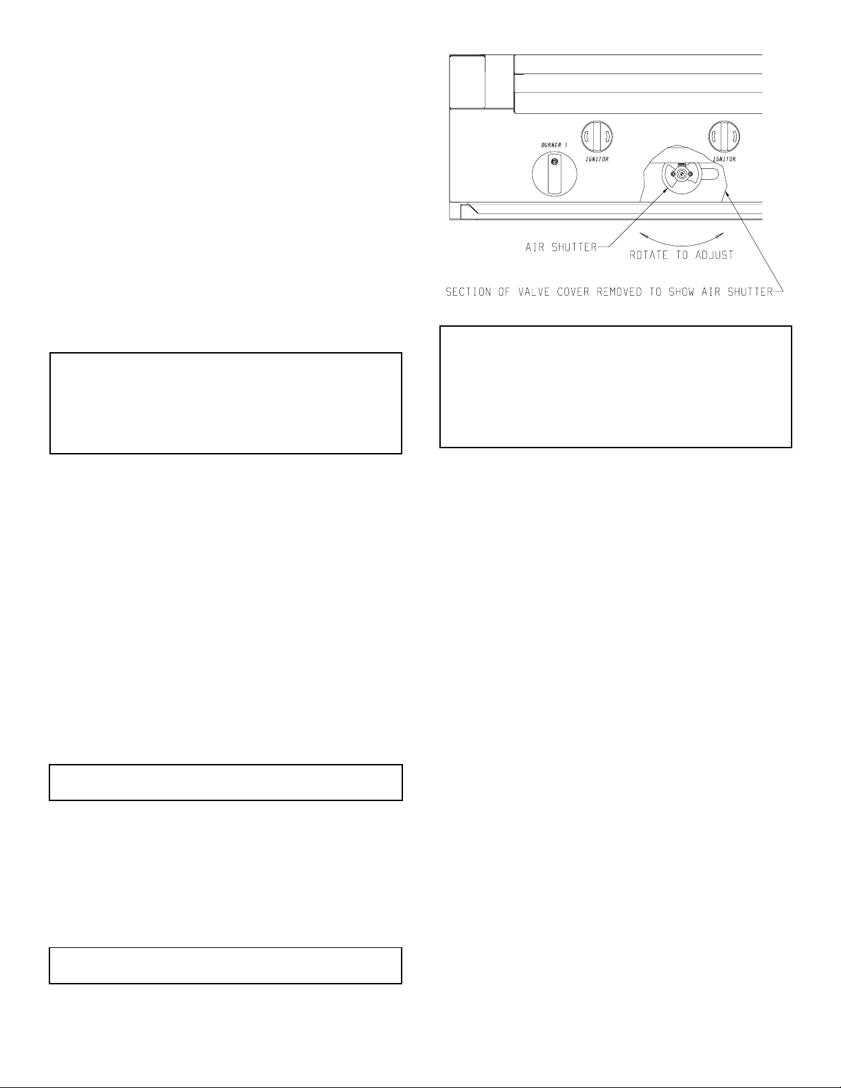
Air Shutter (Figure 5)
Each burner is tested and adjusted at the factory prior to shipment.
However, variations in the local gas supply may make it necessary to
adjust the burners. The flames of the grill burners should be visually
checked. The rotisserie burners should have a very low flame (no more
than 1/4") and glow with an orange color. There is no air shutter
adjustment for the rotisserie burners. On the main burners and side
burner, the flames should be blue and stable with no, excessive noise or
lifting. If the burners do not operate correctly, check if the air shutter or
burner ports are blocked by dirt, debris, spider webs, etc. and proceed
with air shutter adjustment. The amount of air which is drawn into a
burner is governed by a metal cup at the inlet of the burner called an air
shutter.
Figure 5
Air Shutter Adjustment
Be careful as the burners may be very HOT! The air shutters are
located behind the valve cover. There is an access area at the
bottom of the valve cover where you can adjust the air shutter,
with your fingers. A yellow flame indicates insufficient air.
Open the air shutter to allow more air to the burner. If flame is
noisy, blows out, or lifts away from burner or will not light, this
indicates too much air. Close the air shutter.
INSTALLATION CHECK LIST
Note to the Installer: Be sure all items on this list have been thoroughly
completed and checked before operating the grill.
1. Specified clearances maintained to combustibles.
2. All internal packaging removed.
3. Knobs turn freely and bezels centered.
4. Each burner lights satisfactorily, individually or with adjacent
burner lit.
5. Air shutter adjusted.
6. Adjustable low setting satisfactory.
7. Drip trays in place properly and sliding freely.
8. Pressure regulator connected and set for 11.0" w.c. for LP gas.
9. Pressure checked and set at 3.5" w.c. for Natural gas.
10. Grill tested and free of gas leaks.
11. User informed of gas supply shut off valve location.
HOW TO LIGHT YOUR GAS GRILL
WARNING! Before lighting your grill be sure to read this
section carefully.
Turn all knobs to the off position. Inspect the gas supply piping or hose
prior to turning the gas on. If there is evidence of cuts, wear, or abrasion,
it must be replaced prior to use. The replacement pressure regulators and
hose assembly must be the type specified by the manufacturer. Do not
use the Superb gas grill if the odor of gas is present.
For LP gas, the pressure regulator and hose assembly supplied with the
unit must be used. Install the regulator into the tank and check the hose
and regulator connections for leakage with a soap and water solution
before operating your Superb gas grill. Be sure there is gas in the tank.
When lighting your grill always keep your face and body as far
away from the grill as possible.
Lighting the Grill Burners (Figure 6)
The gas grill is equipped with (5) grill burners and (5) piezo ignitors for
the grill burners.
Page 6 R-3848
1. Open the lid.
2. Make sure the grill burner knob to be lighted is in the "OFF"
position.
3. Turn ON gas supply to gas grill.
4. Push and turn the grill burner knob to "HIGH."
5. Be certain that you are turning the ignitor for the grill burner you
intend on using. Rotate ignitor knob clockwise several times. You
will hear a snapping sound, indicating that a spark is being delivered to the burner. You may need to rotate the ignitor knob several
times before the grill burner lights.
6. If the grill burner does not light in 4 seconds, turn the grill burner
knob to "OFF" and wait 5 minutes before repeating Steps 4 and 5.
7. Each grill burner can also be lit with a match attached to a match
holder, if the ignitor fails to light the grill burner.
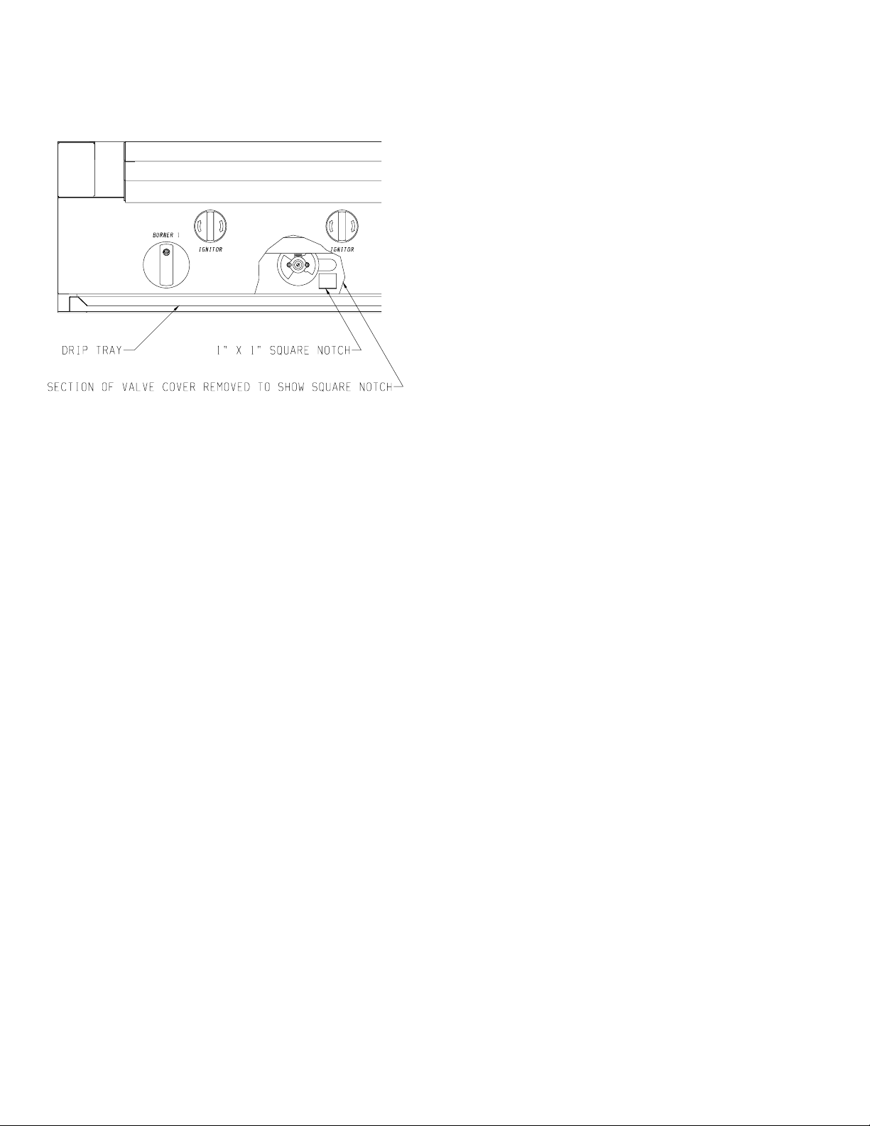
8. To light with a match attached to a match holder, insert lighted
match below valve cover, adjacent to the grill burner knob and
through the 1" x 1" square notch on front liner. Turn the grill burner
knob to "HIGH." Remove and extinguish the match quickly when
the grill burner lights.
Page 7
9. If grill burner does not light, turn all knobs to "OFF" and have a
qualified service technician check grill.
10. Turn all knobs to "OFF" and shut off gas supply when not in use.
If the grill burner will not light after several tries, refer to Troubleshooting section of this manual.
Figure 6
TO PREHEAT GRILL: Once lit, close the lid for approximately 10
minutes to preheat grill.
Lighting the Side Burner
1. Remove the side burner lid and any cooking utensils from the side
burner grate.
2. Make sure the side burner knob is in the "OFF" position.
3. Turn ON gas supply to gas grill.
4. Push and turn the side burner knob to "HIGH."
5. Rotate ignitor knob, between rotisserie burner knob and side burner
knob, clockwise several times. You will hear a snapping sound,
indicating that a spark is being delivered to the side burner. You
may need to rotate the ignitor knob several times before the side
burner lights.
6. If the side burner does not light in 4 seconds turn the side burner knob
to "OFF" and wait at least 5 minutes before repeating Steps 4 and 5.
7. The side burner can also be lit with a match attached to a match
holder if the ignitor fails to light the side burner.
8. To light with a match attached to a match holder, hold the lighted
match next to the side burner ports and turn the side burner knob to
"HIGH." Remove and extinguish the match quickly when the side
burner lights.
9. If side burner does not light, turn knob to "OFF" and have a
qualified service technician check grill.
10. Turn all knobs to "OFF" and shut off gas supply when not in use.
If the side burner will not light after several tries, refer to Troubleshooting section of this manual.
Lighting the Rotisserie Burner
1. Open the lid.
2. Make sure the rotisserie burner knob is in the "OFF" position.
3. Turn ON gas supply to gas grill.
4. Push and turn the rotisserie burner knob to the LEFT position to
light the left, rotisserie burner. If the right, rotisserie burner is to be
used with the left, rotisserie burner turn to the BOTH position.
5. Rotate the ignitor knob, between rotisserie burner knob and side
burner knob, clockwise several times. You will hear a snapping
sound indicating that a spark is being delivered to the rotisserie
burner. You may need to rotate the ignitor knob several times
before the rotisserie burner lights.
6. If the rotisserie burner does not light in 4 seconds, turn the rotisserie
knob to "OFF" and wait 5 minutes before repeating Steps 4 and 5.
7. The rotisserie burner can also be lit with a match attached to a match
holder if the ignitor fails to light the rotisserie burner.
8. To light with a match attached to a match holder, hold the lighted
match next to the rotisserie burner ports on the left, rotisserie burner
and turn the rotisserie burner knob to LEFT. Remove and extinguish the match quickly when the left, rotisserie burner lights. To
light right, rotisserie burner after the left, rotisserie burner has been
lit, repeat process for lighting with a match and turn rotisserie
burner knob to BOTH.
9. If rotisserie burner does not light, turn knob to "OFF" and have a
qualified service technician check grill.
10. Turn all knobs to "OFF" and shut off gas supply when not in use.
If the rotisserie burner will not light after several tries, refer to Troubleshooting section of this manual.
USING YOUR SUPERB GRILL
Safety Practices to Avoid Injury to Self or Property
1. When lighting a burner always pay close attention to what your
doing. Be certain that you are turning the ignitor labeled for the
burner you intend on using.
2. When using the grill: Do not touch the elevated cooking racks, grill
plates, or immediate surrounding area as these areas become
extremely hot and could cause burns.
3. Use only a dry barbecue mitt, moist or damp potholders on hot
surfaces may cause burns from steam. Do not use a towel or bulky
cloth in place of a barbecue mitt. Do not let potholders touch hot
portions of the grill or grill plates.
4. Grease is flammable. Let hot grease cool before attempting to
handle it. Avoid letting grease deposits collect in the drip pans or
drip trays. CLEAN OFTEN.
5. Do not use aluminum foil to line drip trays or drip pans. This can
severely upset combustion air flow or trap excessive heat in the
control area. The result of this can be melted knobs.
6. For proper lighting and performance of the burners keep the ports
clean. It is necessary to clean them periodically for optimum
performance.
7. NEVER GRILL WITHOUT THE DRIP TRAYS IN PLACE and
pushed all the way to the back of the grill. Without the drip trays,
hot grease could leak downward and produce a fire or explosion
hazard.
R-3848 Page 7
8. Do not locate the grill under overhead unprotected surfaces. Use
only in well ventilated areas. Do not use in buildings, garages,
sheds, breezeways, or other such enclosed areas. THIS UNIT IS
FOR OUTDOOR USE ONLY.
9. Keep any electrical supply cord, or the rotisserie motor cord away
from the heated areas of the grill.
10. Never use a dented or rusty LP tank.
11. DO NOT USE CHARCOAL IN THE GRILL.
12. Never place paper inside the grill.
13. Never obstruct the flow of combustion and ventilation air to the
grill.
14. Keep the ventilation opening of the cylinder enclosure free and
clear from debris.
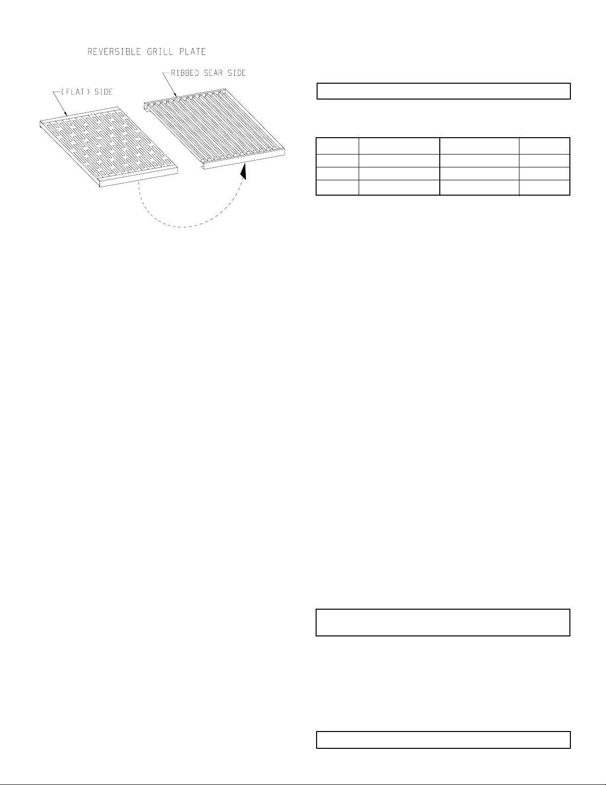
Grill Plates (Figure 7)
An exclusive feature of your Superb gas grill are the stainless steel grill
plates designed to deflect the grease from falling into the burners thereby
reducing flare-ups and extending the life of the burners. The perforations in the stainless steel evens out the heat and creates a hot surface for
the meat drippings to fall on to. This action turns the drippings into
smoke which passes over the meat resulting in a delicious "charcoal
flavor." The grill plates can be turned over to become sear plates. A grill
plate handle is included to turn over grill plates.
Page 8
Thermometers
Your Superb grill comes equipped with a thermometer which reads the
air temperature inside of the lid assembly. Also, a second thermometer
is located in the steamer lid which monitors air temperature.
Figure 7
1. Since these grill plates transfer heat so quickly, evenly, and
efficiently, you may opt to cook on lower heat settings which may
actually result in fuel savings.
2. For best cleaning results, preheat the grill for approximately 10
minutes and then use a brass bristle brush to clean the grill plates.
3. Most cooking will be done on the "Non-Flat" side. Delicate foods
that could fall through (fish, vegetables, etc.) should be prepared on
the reversible flat side. Since most of these foods are dry by nature,
it is suggested that a light coating of cooking oil be applied to the
grill plates before use. Some foods may stick more than others, but
sticking many times may be attributed to the grill plate being too
hot, and lower heat setting is warranted. Again, experimentation is
the key. A sharp edged spatula is also very helpful.
4. Over time the grill plates may change slightly in color. This is
normal and in no way alters performance or durability.
5. The Superb elevated cooking racks are very versatile and can
actually be used to cook food slower than the main grill area. For
rotisserie use, simply remove by lifting off the elevated cooking
racks and grill plates and replace with drip pans.
COOKING
1. Be sure the drip trays are in place and pushed all the way to the back
of the grill.
2. Light the burners using the lighting instructions.
3. Preheat the grill after lighting with burner knob turned to "HI" for
10 minutes. Keep the lid closed while preheating.
4. Place the food on the grill and cook to the desired doneness. Adjust
the heat setting if necessary. The burner knob may be set to any
position between "HIGH", "MEDIUM" and LO."
5. Turn all knobs to "OFF" and shut off gas supply when you are
finished grilling or after burning residue off grates.
6. Clean the cooking grids, drip trays and drip pans after each use.
Grilling requires high heat for searing and proper browning. Most foods
are cooked at the highest heat setting for the entire cooking time.
However, when grilling large pieces of meat or poultry, it may be
necessary to turn the heat to a lower setting after the initial browning,
this will cook the food completely through without burning the outside.
Foods cooked for a long time or basted with a sugary marinade may need
a lower heat setting near the end of the cooking time. The doneness of
the meat, whether rare, medium, or well done, is affected to a large
degree by the thickness of the cut. Trim any excess fat from the meat
before cooking. To prevent steaks or chops from curling during cooking,
slit the fat around the edges at 2-inch intervals. When defrosting meats,
it is recommended that it be done overnight in a refrigerator as opposed
to a microwave as the microwave can dry out or even partially cook the
meat.
Never allow the air temperature inside the grill to go above 500
Cooking Chart for Desired Doneness
Insert an instant read thermometer directly into center of meat to check
for doneness.
MEAT RARE MEDIUM WELL
Beef 135° - 140°F 150° - 160°F 170°F
Pork not recommended not recommended 170°F
Poultry not recommended 170°F 185°F
Indirect Cooking
Indirect cooking is a cooking technique that is similar to roasting and
baking in the oven. To cook with indirect heat turn Burner 1 and Burner
5 on High and Burner 3 on Low. Refer to the Cooking Chart for desired
doneness of meat. Also, pastries can be baked with the same indirect
cooking technique. Baking time will be similar to the recipe instructions. Monitor the thermometer in the lid to maintain temperature in any
recipe instructions. All burner settings may need to be adjusted, depending on outside temperature and wind conditions.
Flare-Ups
Always remember to pre-heat the grill for ten (10) minutes before
starting to cook. When you cook fatty foods over an open flame, you can
expect flare-ups. Natural juices falling on the hot plaques result in flame
and smoke that give foods cooked on your grill that delicious outdoor
flavor and appearance. Expect and encourage a moderate amount of
flare-up. Excessive flare-ups occur when cooking extra fatty foods, or
if cooking temperatures are too high. Control flare-ups by:
1. Turn your burner knob to a lower setting.
2. Move the meat to another part of the grill, if possible. You can cook
on one side and move food, as necessary, to the unlighted side.
3. Trim of excess fat before cooking.
4. To avoid flare-ups fatty meats should be cooked on the medium
setting.
5. Cook with the lid assembly down. Cutting off the flow of air will
reduce the possibility of flare-ups.
6. If you need to immediately control an excessive flare-up, throw a
small amount of baking soda directly on the plaques and lower heat
setting.
NOTE: Do not douse flare-ups with liquid as this can intensify
the flame and harm the grill plates.
Chip Tray
Your Superb gas grill includes a built-in chip tray which installs directly
into the front of grill. We believe that wood chips enhance the flavor of
everything that is grilled. To use the chip tray, place a handful of soaked
wood chips in the tray, then ignite the burners to the left and right of the
tray. Turn the burners on "HI" for 10 minutes. Next reduce the flame to
"MEDIUM" or "LO" to keep the chips from burning too fast.
CAUTION: When adding more chips to the tray the handle
on tray may be Hot.
Top Burners
Your Superb gas grill is equipped with (5) grill burners, each rated at
12,000 BTUH and has (5) spark ignitors for easy lighting. Provided for
use with your side burner rated at 30,000 BTUH is a stainless steel lid
which doubles as work surface when the burner is not in use. When using
the grill with the side burner covered, be careful as heat can conduct from
the grill and cause the lid to heat up. Always remove the lid before
lighting the side burner.
Never light or use the side burner with the lid in place.
°F.
Page 8 R-3848
Page 9
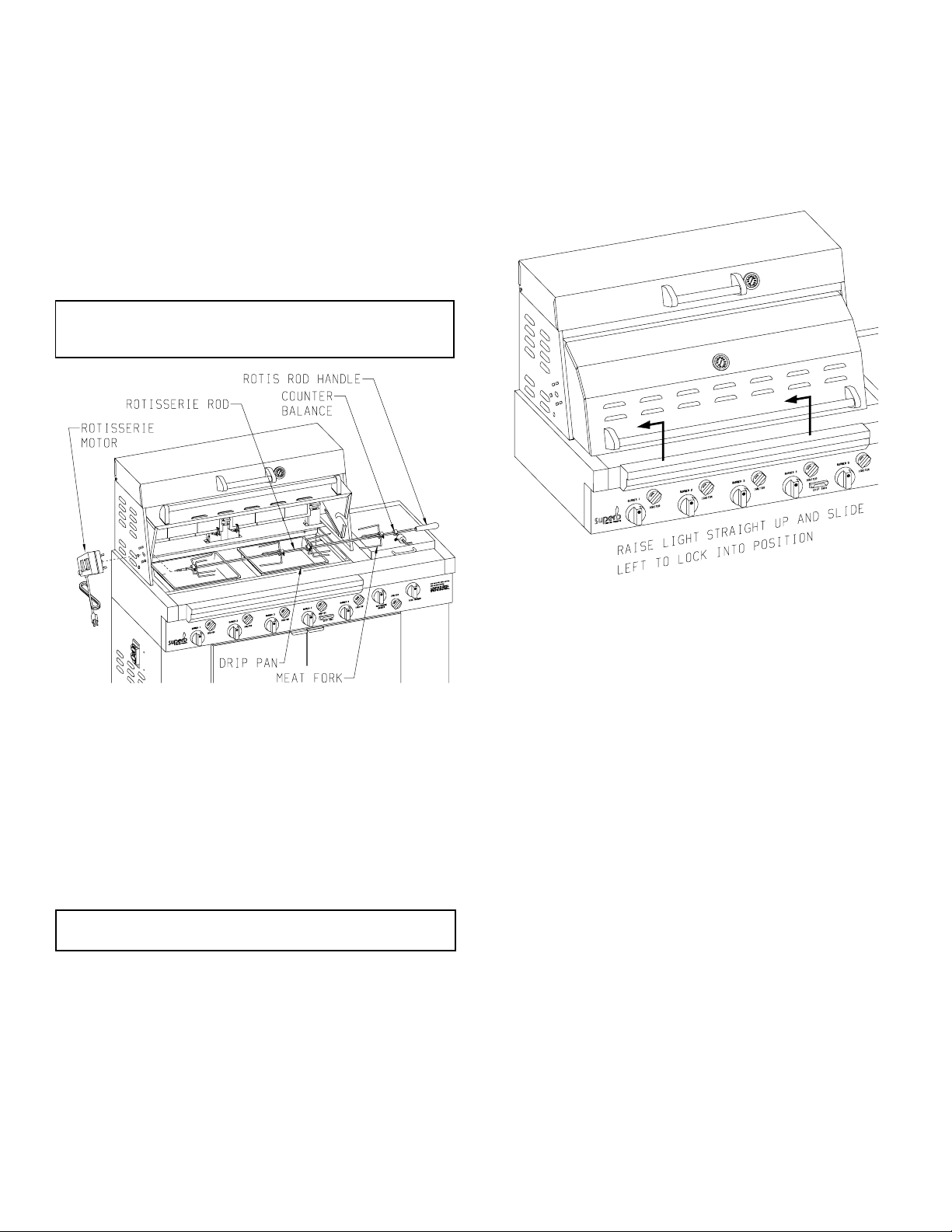
Rotisserie (Figure 8)
The (2) rotisserie burners, each rated at 12,000 BTUH, are an infrared
type which provide intense searing radiant heat. This intense heat is
perfect for searing in the natural juices and nutrients found in quality
cuts of meats. When lit, the rotisserie burners will reach cooking
temperatures in about 3 minutes. The orange/red glow will even out in
about 5 minutes.
The rotisserie motor is equipped with gears capable of turning up to a 20
lb. cut of meat or poultry. The motor is mounted to a stainless steel bracket
which attaches to the left side of the grill. The rotisserie motor must be
electrically grounded in accordance with local codes or, in the absence of
local codes, with the National Electrical Code, ANSI/NFPA 70 or
Canadian Electrical Code, CSA C22.1, if an external electrical source is
utilized.
WARNING! DO NOT use the rotisserie and the 5 main burners
at the same time! You CAN use the LEFT rotisserie and the two
far RIGHT main burners (#4 and #5) at the same time.
Once the food is secure, attach the counterbalance to rotisserie rod.
Remove the elevated cooking racks and grill plates. Insert the drip pans
into grill onto the ceramic plaques. Center drip pan(s) under food being
rotisserized. Insert the rotisserie rod into the motor. Turn on rotisserie
motor and adjust counterbalance.
NOTE: After the first use of your rotisserie it is likely that the stainless
steel above the rotisserie burners will darken to a dark, blue color. The
electric motor should be removed and stored in a dry place when not in
use.
Figure 8
Counterbalance
Counterbalance is used to balance the rotisserie rod when cooking large
or irregular pieces of food. The food will always be placed on the
rotisserie rod between the motor and counterbalance. Adjust the counterbalance on the rotisserie rod until the food turns in an even motion.
The rotisserie rod for the rotisserie fits into the motor assembly by
placing the pointed end into the motor and the opposite end on the
support at the right side of the grill. With the rotisserie rod pushed in as
far as possible into the motor, the grooved rotisserie rod should rest on
the right side bracket. The removable handle should only be in place
when handling the rotisserie rod.
When using the side burner, remove the rotisserie rod handle
to prevent it from getting hot!
To load the rotisserie rod begin with the handle in place, and slide one
of the meat forks with prongs facing away from the handle onto the
rotisserie rod. Push the rotisserie rod through the center of the food, then
slide the second meat fork with prongs towards the food on the rotisserie
rod. Center the food on the rotisserie rod then push the meat forks firmly
into the food. Tighten the wing nuts. It may be necessary to wrap the food
with butchers string (never use nylon or plastic string) to secure any
loose portions.
Figure 9
Grill Light (Figure 9)
Exclusive on Superb grill is the grilling area fluorescent light. The
fluorescent light is wired at the factory and should be plugged directly
into a properly grounded three-pronged receptacle. Raise light and slide
to left to lock into position.
Replacement of Fluorescent Bulb
1. Remove electrical cord for fluorescent bulb from electrical receptacle.
2, Remove light housing front from light housing rear by removing (3)
Phillips head screws located at bottom of light housing front.
3. Replace fluorescent bulb with part number R-3932, fluorescent bulb.
Refer to page 12 for ordering repair parts.
4. Attach light housing front onto light housing rear with (3) Phillips
head screws from Step 2.
Steamer
Use your steamer for steaming vegetables and for keeping food warm.
Optional large and small steamer pans, SSP-1 are available for the
steamer.
Elevated Cooking Racks
The two cooking racks can be used to cook food with indirect heat. The
cooking time will be increased but the food will be moist and flavorful.
The rotisserie burners are located beneath the elevated cooking racks.
Grease may accumulate on the rotisserie burners from use of the
elevated cooking racks. Ignite rotisserie burners to "burn off" any grease
accumulation. The elevated cooking racks must be removed when the
rotisserie burners are in use.
R-3848 Page 9
Page 10
CARE AND MAINTENANCE
Stainless Steel
The Superb gas grill is made from stainless steel. There are many different
stainless steel cleaners available. Always use the mildest cleaning methods first, scrubbing in the directions of the grain. To touch up noticeable
scratches in the stainless steel, sand lightly with dry 100 grit emery paper
or scotch bright pad in the direction of the grain. Specks of grease can
gather on the surfaces of the stainless steel and bake on to the surface
giving the appearance of rust. To remove this grease buildup scrub with
a strong degreaser in the direction of the grain. Coat with lemon oil or a
stainless steel shine product to protect its finish after cleaning.
Cleaning Grill Plates
The grill plates should be cleaned regularly because of grease build-up
and other debris. Keeping the grill plates clean will greatly reduce flare
ups and grease fires.
The easiest way to clean the grill is immediately after cooking is
completed. Be sure the burners are turned off and there are no flames
before beginning. Wear a barbecue mitt to protect your hand from the heat
and steam. Using a brass bristle barbecue brush, scrub the hot grill plates.
If the grill is allowed to cool before cleaning, the cleaning process will be
more difficult.
NOTE: DO NOT USE CAUSTIC CLEANERS such as oven
cleaners, etc. This will damage the grid surface and void your
warranty.
Side Burner Grate
The side grate is stainless steel. Do not attempt to clean a hot grate. When
the grate cools it may be wiped with hot soapy water, then rinsed and
wiped dry. Never immerse a hot grate in water as the hot steam produced
could cause burns.
Drip Trays
The drip trays will collect grease from the grill area. Do not attempt to
remove or clean until thoroughly cooled. To avoid grease fires or flareups be sure to clean out the grease often.
Grill Burners
The grill burners are constructed of cast stainless steel and should only
require minimal maintenance. However, they should be checked periodically and cleaned if needed.
Side Burner
The side burner is constructed of cast stainless steel. Occasional cleaning
of the burner ports will be necessary.
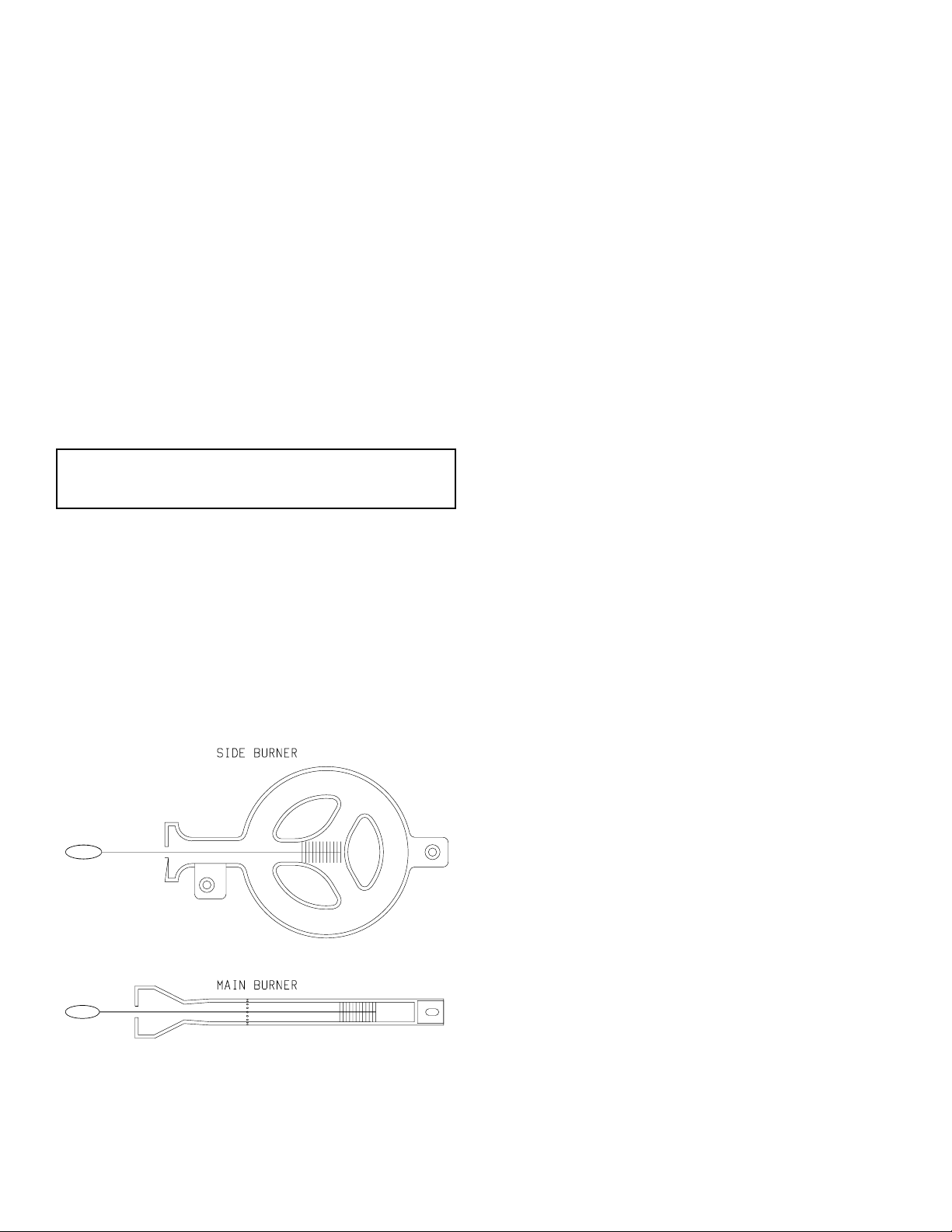
Flashback from Spiders (Figure 10)
In some areas of the country, spiders or small insects have been found to
create "flashbacks" problems. The spiders spin webs and/or insects build
nests in the burner venturi tube(s). The web and/or nests can lead to gas
flow obstruction which results in a "flashback" (a fire in the venturi
tube(s). Clean interior of burners with a flexible, soft bristle, bottle brush
in order to remove spiders, spider webs and debris.
CLEANING PRODECURES
Removing Main Burners (Figure 11)
1. Turn OFF gas supply to grill.
2. All grill parts must be cool before attempting to clean.
3. Remove the chip tray.
4. Remove (4) grill plates.
5. Remove ceramic plaques and plaque rack.
6. Remove (5) burner hoods located above main burners.
7. Remove right end and left end of inner liner by removing (2) screws
from each end.
8. Remove inner liner by removing (6) screws.
9. Remove (1) bolt from each main burner.
10. Lift rear section of main burner in order to remove main burner from
orifice fitting.
11. Clean interior of main burner with a flexible, soft bristle, bottle brush
in order to remove spiders, spider webs and debris. Apply air
pressure to burner ports to remove debris.
12. Be careful not to change the air shutter's original position. Once
reinstalled, light all of the burners and check for proper flame.
13. To replace main burners, reverse above procedure starting with Step
10.
Removing Side Burner (Figure 11)
1. Turn OFF gas supply to grill.
2. All grill parts must be cool before attempting to clean.
3. Remove side burner lid.
4. Remove side burner grate.
5. Remove (2) screws from side burner.
6. Lift rear section of side burner in order to remove side burner from
orifice fitting.
7. Clean interior of side burner with a flexible, soft bristle, bottle brush
in order to remove spiders, spider webs and debris. Apply air
pressure to burner ports to remove debris.
8. To replace side burner, reverse above procedure starting with Step
6.
Additional Steps to Clean Main Burners and Side Burner
1. Turn OFF gas supply to grill.
2. All grill parts must be cool before attempting to clean.
3. Clean the exterior of the burner with a wire brush.
4. Clear any clogged ports with a straightened paper-clip.
5. Never use a wooden toothpick as it may break off and clog the port.
6. Shake out any debris through the air shutter.
7. Use a flashlight to inspect the burner inlet to ensure it is not blocked.
8. If an obstruction can be seen, use a straightened metal wire coathanger to clean it out.
Figure 10
Page 10 R-3848
Page 11
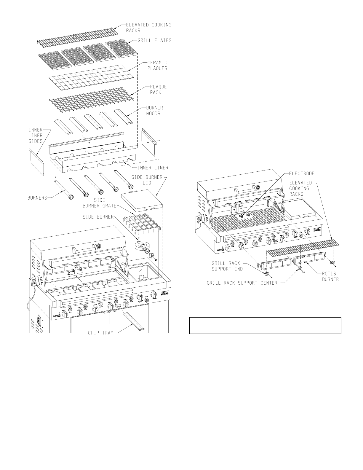
4. Pull forward on the electrode to expose approximately 3 inches of the
electrode wire.
5. If you are replacing the electrode, remove the electrode wire from the
electrode. Do not allow the electrode wire to slip back into the access
hole.
6. If you are not replacing the electrode, allow the electrode to lay on
the cooking surface.
7. Remove (6) screws from the brackets for the elevated cooking racks.
The brackets are located at each end (2 brackets) and between (1
bracket) the rotisserie burners.
8. At the center of the gas grill, grasp the end of rotisserie burner, pull
forward and slide the opposite end of the rotisserie burner from the
orifice fitting.
9. Apply air pressure into the face and end of the rotisserie burner to
remove spiders, spider webs, dust, lint and debris. A flexible, soft
bristle, bottle brush can be used to clean the interior of the rotisserie
burner.
10. Remove the rotisserie burner orifice from the orifice fitting.
11. Apply air pressure into the rotisserie burner orifice and orifice fitting
to remove spiders, spider webs, dust, lint and debris. A flexible, soft
bristle, bottle brush can be used to clean the orifice fitting.
12. To reinstall components, reverse above procedure starting with Step
10.
Figure 12
Cleaning the Orifices
No regular maintenance should be needed for the orifices. They should
only be removed if it is determined that there is a blockage.
Warning: Serious injury may occur if the orifice is not located
properly in the orifice fitting when reassembled.
Figure 11
Removing Rotisserie Burners and Rotisserie Burner Orifices
(Figure 12)
1. Turn OFF gas supply to grill.
2. All grill parts must be cool before attempting to clean.
3. Remove (1) screw from each rotisserie burner electrode.
R-3848 Page 11
Removing and Replacing the Piezo Ignitors and Electrodes
1. Remove all gas control knobs and ignitor knobs.
2. Remove chip tray.
3. Remove valve cover (7 screws).
4. Piezo ignitors are located at rear of valve cover.
5. Remove (1) screw for each electrode.
6. Remove (2) screws for each piezo ignitor.
7. Reverse above procedure to replace components.
Page 12
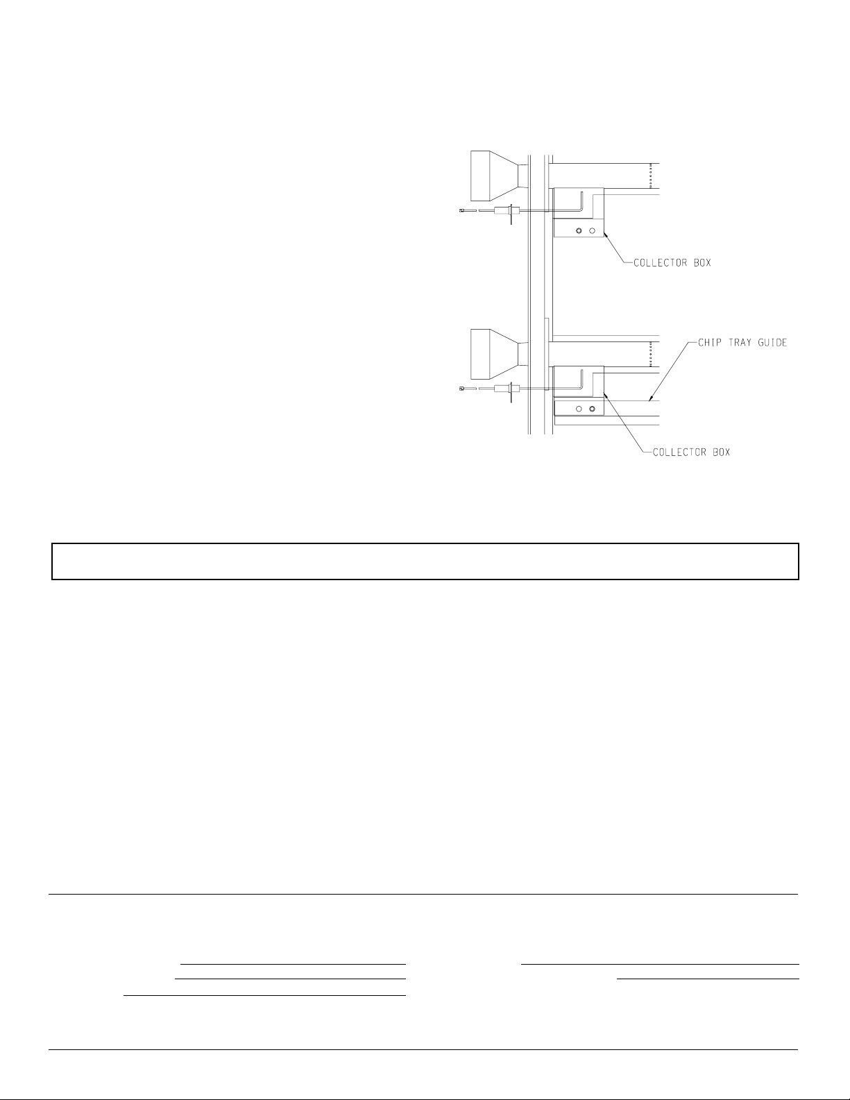
Adjusting Main Burner Electrodes
1. Remove four (4) grill plates.
2. Remove ceramic plaques.
3. Remove plaque rack.
4. Remove five (5) burner hoods from five (5) main burners.
5. Remove five (5) collector boxes from five (5) main burner electrodes,
one (1) 10 - 16 x 1/2" Phillips stainless steel screw for each collector
box.
6. At this time, check for proper sparking of the electrodes. Turn
electrode knob, the spark should occur between the second and third
port hole on main burner.
To adjust spark angle you will use two (2) needle nose pliers.
Grasping electrode wire 1/2" back from tip of electrode with first
pair of needle nose pliers adjust tip of electrode with second pair of
needle nose pliers.
7. Check ignition of main burners. Make additional adjustments to
electrodes if required.
8. Locate main burner with electrode that is to the left of chip tray.
Place collector box over electrode. Place flange on collector box
beneath flange on chip tray guide. The clearance hole in collector
box will align with clearance hole in chip tray guide. Insert and
attach one (1) 10-16 x 1/2" Phillips stainless steel screw from Step
5 through chip tray flange and collector box flange and into bottom
of inner liner.
9. Place four (4) additional collector boxes over four (4) additional
main burners with electrodes.
10. Attach four (4) collector boxes to bottom of inner liner with four
(4) 10-16 x 1/2" Phillips stainless steel screws from Step 5.
11. Replace five (5) burner hoods over five (5) main burners.
12. Replace plaque rack.
13. Replace ceramic plaques onto plaque rack.
14. Replace four (4) grill plates.
15. Adjustment of main burner electrodes is completed.
TROUBLE-SHOOTING
If your Superb gas grill does not function properly, use the following checklist before contacting your dealer for service.
You may save the cost of a service call.
1. Grill won't light when the rotary ignitor is turned.
a. With the gas tuned off, remove the grill plates, ceramic
plaques and plaque rack. Turn the ignitor knob clockwise
to check the spark. You should see a spark jump from tip of
the ignitor. If there is a spark, check the gas supply. Is the
tank full? Is the line purged of air? Can you light the burner
with a match?
b. Check air shutter adjustment, close as needed.
c. Do other burners light?
d. Check the orifice for blockage.
e. Is the ignitor tip clean and free from debris?
f. Clean ignitor tip.
2. Burner flame is yellow or orange and there is a smell of gas.
a. Check the burner inlet for obstructions.
b. Check the air shutter for proper adjustment.
c. Check for spiders, spider webs and debris.
3. Low heat with control knob set on "HI."
a. Is the fuel hose bent or kinked?
b. Is there an adequate gas supply?
HOW TO ORDER REPAIR PARTS...
All parts listed in the Parts List have a part No. When ordering parts, first obtain the Model No. from the nameplate on your equipment. Then determine
the Part No. (not the Index No.) and the Description of each part from the appropriate illustration and list. Be sure to give all this information...
c. If there is only one burner that appears low, does the orifice
or burner need cleaning?
d. Is the air shutter too far open or closed?
e. Is the gas supply, or gas pressure low?
f. Has the grill been preheated for at least 10 minutes?
4. The smell of gas with flames appearing yellow or the gas grill
does not reach temperature and heats unevenly.
a. Check for spiders or insects.
b. Spiders and insects can nest in the burner of this or any
grill, and cause a disruption in the flow of gas from the
burner. This is dangerous and can cause a fire behind the
valve cover, damaging the grill and making it unsafe to
operate.
You should inspect the burners periodically or immediately if any of these conditions occur or persist.
5. The burners make popping noises.
a. Check air shutter adjustment.
b. Check burners for clogged ports.
Grill Model Number Part Description
Grill Serial Number Type of Gas (Propane or Natural)
Part Number
Do not order bolts, screws, washers or nuts. They are standard hardware items and can be purchased at any local hardware store. Order parts through your
local dealer.
Shipments contingent upon strikes, fires, and all causes beyond our control.
Page 12 R-3848
Empire Comfort Systems, Inc. Nine Eighteen Freeburg Ave. Belleville, Illinois 62222-0529
Page 13

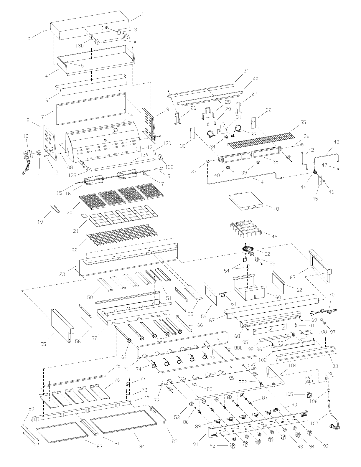
PLEASE NOTE: When ordering parts, it is very important that part number and description of part coincide.
Index Part
No. Number Description
1 SSG-140 STEAMER LID ASSEMBLY
1A SSG-126 HANDLE - STEAMER LID
2 R-4005 SHOULDER SCREW (STEAMER) (2 REQ’D)
3 R-3987 THERMOMETER - STEAMER
4 SSG-040 STEAMER BODY
5 R-4010 NUT (4 REQ’D) 1/4-20 STAINLESS
6 SSG-029 WIND GUARD
7 SSG-030 TOP-BACK
8 SSG-105 TOP END-LEFT WELDED ASSEMBLY
9 SSG-106 TOP END-RIGHT WELDED ASSEMBLY
10 R-4003 MOTOR
11 SSG-055 ROTIS MOTOR SUPPORT
12 R-3999 SHOULDER SCREW (COVER) (2 REQ’D)
13 SSG-107 LID ASSEMBLY-COMPLETE
13A SSG-109 HANDLE - COVER LID
13B R-3928 HANDLE BRACKET - LEFT
13C R-3929 HANDLE BRACKET - RIGHT
13D R-3930 INSULATOR (4 REQ’D)
14 R-3857 THERMOMETER - COVER
15 R-3877 ROTIS ROD
16 R-3960 MEAT FORK (4 REQ’D)
17 R-3957 COUNTERBALANCE
18 R-3910 HANDLE - ROTIS ROD
19 R-3881 GRATE REMOVER
20 SSG-112 GRILL PLATE WELDED ASSEMBLY (4 REQ’D)
21 R-3995 CERAMIC PLAQUE (BOX OF 70)
22 SSG-116 PLAQUE RACK WELDED ASSEMBLY
23 SSG-003 CASING BACK
24 SSG-056 ROTIS SUPPORT TOP
25 SSG-051 ROTIS SHIELD (NAT GAS ONLY)
26 SSG-060 ROTIS SUPPORT-LEFT
27 SSG-059 ROTIS SUPPORT-RIGHT
28 SSG-057 ROTIS SUPPORT CENTER
29 SSG-137 WIRE TUBE (2 REQ’D)
30 SSG-062 ROTIS SUPPORT COVER-LEFT
31 SSG-058 ROTIS SUPPORT COVER-CENTER
32 SSG-061 ROTIS SUPPORT COVER-RIGHT
33 R-3955 ELECTRODE WIRE ASSEMBLY - 52" LONG (2
REQ’D)
34 R-3915 ELECTRODE (2 REQ’D)
35 SSG-117 ELEVATED COOKING RACK (2 REQ’D)
36 R-2319 ORIFICE - ROTIS BURNER (LP GAS ONLY) (2
REQ’D)
36 R-4000 ORIFICE - ROTIS BURNER (NAT GAS ONLY) (2
REQ’D)
37 P-232 ORIFICE HOLDER (2 REQ’D)
38 R-3919 BURNER - ROTIS (2 REQ’D)
39 SSG-031 GRILL RACK SUPPORT CENTER
40 SSG-054 GRILL RACK SUPPORT END (2 REQ’D)
41 SSG-136 INLET TUBING ASSEMBLY - ROTIS VALVE TO
ROTIS BURNER - LEFT
42 SSG-135 INLET TUBING ASSEMBLY - ROTIS VALVE TO
ROTIS BURNER - RIGHT
43 SSG-134 INLET TUBING ASSEMBLY - MANIFOLD TO
ROTIS VALVE
44 R-3870 VALVE - ROTIS
45 SSG-052 VALVE BRACKET-ROTIS
46 R-1652 VALVE NUT
47 R-4007 BRASS MALE CONNECTOR (BODY ONLY)
48 SSG-111 SIDE BURNER LID ASSEMBLY
49 SSG-118 SIDE BURNER GRATE WELDED ASSEMBLY
50 SSG-022 BURNER HOOD (5 REQ’D)
51 SSG-020 CHIP TRAY GUIDE (2 REQ’D)
52 R-3967 SIDE BURNER
53 R-3358 AIR SHUTTER (6 REQ’D)
54 SSG-103 SIDE BURNER BRACKET WELDED ASSEMBLY (2
REQ’D)
55 SSG-099 CASING SIDE-LEFT SUB-ASSEMBLY
56 SSG-014 INNER LINER SIDE (2 REQ’D)
57 SSG-013 INNER LINER
Index Part
No. Number Description
58 SSG-010 CASING DIVIDER
59 SSG-025 INNER LINER SIDE BURNER-LEFT
60 SSG-024 INNER LINER-SIDE BURNER
61 R-3958 ELECTRODE AND WIRE ASSEMBLY - SIDE
BURNER
62 SSG-026 INNER LINER SIDE BURNER-RIGHT
63 SSG-100 CASING SIDE-RIGHT SUB-ASSEMBLY
64 R-3916 MAIN BURNER (5 REQ’D)
65 SSG-019 CHIP TRAY
66 SSG-053 ROTIS WIRE GUIDE
67 SSG-102 CASING FRONT ASSEMBLY
68 SSG-104 LIGHT HOUSING-REAR WELDED ASSEMBLY
69 R-3934 SHOULDER SCREW (LIGHT) (2 REQ’D)
70 R-4020 CORD SET
71 SSG-005 FRONT SHIELD
72 R-3873 CONTROL ROD
73 SSG-004 FRONT LINER
74 R-3921 ELECTRODE AND WIRE ASSEMBLY - MAIN
BURNER (5 REQ’D)
75 SSG-016 INNER LINER SPACER
76 SSG-015 GREASE PAN SHIELD (5 REQ’D)
77 SSG-049 MANIFOLD BRACKET REAR-UPPER
78 SSG-050 MANIFOLD BRACKET REARLOWER
79 SSG-101 BURNER SUPPORT WELDED ASSEMBLY
80 SSG-007 WIRE CHANNEL-LEFT
81 SSG-009 GREASE PAN DIVIDER
82 SSG-008 WIRE CHANNEL-RIGHT
83 SSG-017 GREASE PAN-LEFT
84 SSG-018 GREASE PAN-RIGHT
85 SSG-023 VALVE COVER SUPPORT (4 REQ’D)
86 R-3357 SPRING (6 REQ’D)
87 R-3874 VALVE AND ORIFICE ASSEMBLY - NAT ONLY -
MAIN BURNER (5 REQ’D)
87 R-4112 VALVE AND ORIFICE ASSEMBLY - LP ONLY -
MAIN BURNER (5 REQ’D)
88a R-4118 VALVE - NAT ONLY - SIDE BURNER
88a R-4119 VALVE - LPG ONLY - SIDE BURNER
88b R-4121 ORIFICE ASSEMBLY - LP ONLY - SIDE BURNER
88b R-4120 ORIFICE ASSEMBLY - NAT ONLY - SIDE
BURNER
89 R-3908 PIEZO IGNITOR (5 REQ’D)
90 R-3966 PIEZO IGNITOR (3-SPARK)
91 SSG-012 VALVE COVER
92 R-3918 KNOB (MAIN AND SIDE BURNERS) (6 REQ’D)
93 R-3909 KNOB (6 REQ’D) (PIEZO IGNITORS)
94 R-3872 KNOB (ROTIS BURNER)
95 R-3939 GLASS
96 R-3940 BULB CLIP
97 R-1468 STRAIN RELIEF BUSHING
98 R-3932 BULB - FLUORESCENT
99 R-3933 SOCKET
100 R-3931 BALLAST
101 R-3920 SWITCH
102 SSG-035 LIGHT MOUNTING BRACKET
103 SSG-032 LIGHT HOUSING-FRONT
104 SSG-110 MANIFOLD WELDED ASSEMBLY
105 R-4015 PRESSURE REGULATOR (NAT GAS ONLY)
106 R-3993 INLET ADAPTOR (LP GAS ONLY)
107 R-3992 HOSE ASSEMBLY 22" LONG (LP GAS ONLY)
108 R-4660 COVER END SPACER (2 REQ’D)
NOT SHOWN R-4052 DRIP PAN (2 REQ’D) STAINLESS
NOT SHOWN R-4116 ORIFICE NAT #50 - MAIN BURNER
NOT SHOWN R-4117 ORIFICE LP #60 - MAIN BURNER
NOT SHOWN R-4120 ORIFICE NAT #37 - SIDE BURNER
NOT SHOWN R-4121 ORIFICE LP #51 - SIDE BURNER
NOT SHOWN R-734 LIGHTER ROD
NOT SHOWN SSG-166 ROTIS SUPPORT-CENTER GASKET
NOT SHOWN SSG-168 ROTIS SUPPORT COVER-CENTER GASKET
NOT SHOWN SSG-176 COLLECTOR BOX (5 REQUIRED)
NOT SHOWN R-7067 ADAPTOR 3/8" MALE SAEX, 1/2" MALE NPT
R-3848 Page 13
Page 14
Page 14 R-3848
 Loading...