

Page 1

PC2CART-1, DC2CART-1
INSTALLATION INSTRUCTIONS
VERIFY THAT ALL PARTS LISTED ON THE EXPLODED VIEW OF THIS MANUAL HAVE BEEN INCLUDED IN
THIS CART BEFORE BEGINNING INSTALLATION.
AUTION: USE CAUTION WHEN HANDLING PARTS, AS THEY MAY CONTAIN SHARP EDGES.
C
WORK GLOVES ARE RECOMMENDED TO PREVENT INJURY.
KEEP THIS OWNER’S MANUAL FOR FUTURE REFERENCE.
EMPIRE COMFORT SYSTEMS, INC • 918 FREEBURG AVE. • BELLEVILLE, IL 62220
Page 1
Page 2

TABLE OF CONTENTS
CONGRATULATIONS!
You have chosen the finest grill for your outdoor cooking pleasure. Please take time to read this entire manual
before assembling your premium Broilmaster® accessory.
Important Information ......................................................................................................................................3
PC Hardware Package ................................................................................................................................... 4
DC Hardware Package ................................................................................................................................... 5
Cart Exploded View ........................................................................................................................................
Cart Parts List ................................................................................................................................................. 7
Cart Assembly .................................................................................................................................................
Fixed Base Assembly ...................................................................................................................................
6
8
10
THIS GAS ACCESSORY IS DESIGNED FOR OUTDOOR USE ONLY
IMPORTANT
THIS MANUAL SHOULD BE READ THOROUGHLY BY THE PERSON INSTALLING THE GRILL CART AND ALL PERSONS WHO WILL USE AND MAINTAIN
THE GRILL MOUNTING. THE INSTALLER SHOULD BE SURE THE MANUAL IS LEFT IN THE POSSESSION OF THE USER. THE USER SHOULD RETAIN
THIS MANUAL FOR FUTURE REFERENCE WHEN USING OR CLEANING THE GRILL CART AND TO PROPERLY IDENTIFY ANY REPAIR PARTS THAT MAY
BE REQUIRED.
WARNING
REFERENCE THIS MANUAL FOR PROPER INSTALLATION AND MAINTENANCE INSTRUCTIONS. IMPROPER INSTALLATION, ADJUSTMENT, ALTERATION,
SERVICE OR MAINTENANCE CAN CAUSE PERSONAL INJURY OR PROPERTY DAMAGE. FOR ASSISTANCE OR ADDITIONAL INFORMATION CONSULT A
QUALIFIED INSTALLER, SERVICE AGENCY OR THE GAS SUPPLIER.
CAUTION:
THE GRILL AND ITS INDIVIDUAL SHUTOFF VALVE MUST BE DISCONNECTED FROM THE GAS SUPPLY PIPING SYSTEM DURING ANY PRESSURE TESTING
OF THAT SYSTEM AT TEST PRESSURES IN EXCESS OF 1/2 PSIG.
CAUTION:
THE GRILL MUST BE ISOLATED FROM THE GAS SUPPLY PIPING SYSTEM BY CLOSING ITS INDIVIDUAL MANUAL SHUTOFF VALVE DURING ANY PRES-
SURE TESTING OF THE GAS SUPPLY PIPING SYSTEM AT TEST PRESSURES EQUAL TO OR LESS THAN 1/2 PSIG.
CAUTION:
PARTS MAY HAVE SHARP EDGES. WEAR LEATHER WORK GLOVES AND HANDLE PARTS CAREFULLY DURING THE UNPACKING, ASSEMBLY AND
THE INSTALLATION.
WARNING
DO NOT SUPPLY LP GAS TO A GRILL DESIGNED FOR NATURAL GAS NOR NATURAL GAS TO A GRILL DESIGNED FOR LP
GAS.
NOTICE
ASSEMBLE GRILL CART BEFORE ASSEMBLING GRILL.
Page 2 B100999-2-0807
Page 3

IMPORTANT INFORMATION
Grill Location
Broilmaster® Premium Gas Grills are designed for
outdoor use ONLY.
This cart is are designed for use with Broilmaster
grills and must not be used with any other grill or for
any other purpose.
Never install or operate your grill in any building, garage,
or other enclosed area.
For your safety, the grill should not be installed or oper
ated under any combustible materials, such as carports,
covered porches, awnings, or overhangs.
Never install or use your grill in or on any recreational
vehicle or boat.
CAUTION: T
AT CLEARANCES LESS THAN SPECIFIED BELOW MAY LEAD TO
THE POSSIBILITY OF FIRE, PROPERTY DAMAGE, OR PERSONAL
INJURY.
A minimum clearance of sixteen (16") inches is required
from all sides of the grill to any combustible material.
HE INSTALLATION AND OPERATION OF THIS GRILL
®
gas
Gas Types
Never use liquid propane gas with a grill designed for
natural gas, or natural gas with a grill designed for liquid
propane gas. The type of gas required for your grill is
defined on its product identification label. Questions
regarding different types of gases should be directed
to your gas supplier.
Cleaning
The exterior of your cart may be cleaned with hot water
and mild detergent as needed.
Touch-up paint is available through your Broilmaster
dealer.
Stainless steel surfaces may be cleaned with a sprayon stainless steel cleaner available at most hardware
stores.
Important: Do not use harsh or abrasive cleaners!
Your cart has a highly polished surface and may be
easily scratched.
®
A minimum clearance of eighteen (18") inches is re
quired from the back of the grill to any combustible
material.
Examples of combustible materials are patio furniture,
fences, or the wall of your home.
The area surrounding the grill should be clear to ensure
proper ventilation. Do not obstruct the flow of com
bustion and ventilation air in any way. The ventilation
openings on the propane cylinder enclosure must also
remain free and clear of debris.
WARNING: D
WHERE GASOLINE OR OTHER FLAMMABLE MATERIALS ARE USED
OR STORED. FAILURE TO COMPLY WITH THIS WARNING COULD
RESULT IN EXPLOSION OR FIRE CAUSING PROPERTY DAMAGE OR
PERSONAL INJURY.
O NOT INSTALL OR OPERATE A GAS GRILL
-
Periodic Inspection and
Maintenance
Periodic inspections and maintenance are essential. All
Broilmaster® Gas Grill products or mechanical devices
eventually begin to wear due to environment, contaminants, corrosion or aging. Inspect all components at
-
least twice per year and replace any that show wear.
If any parts are damaged or missing, you may order parts
from your local Broilmaster
Parts Diagram and Parts List section of this manual for
more detailed information.
®
dealer. Please refer to the
Page 3B100999-2-0807
Page 4
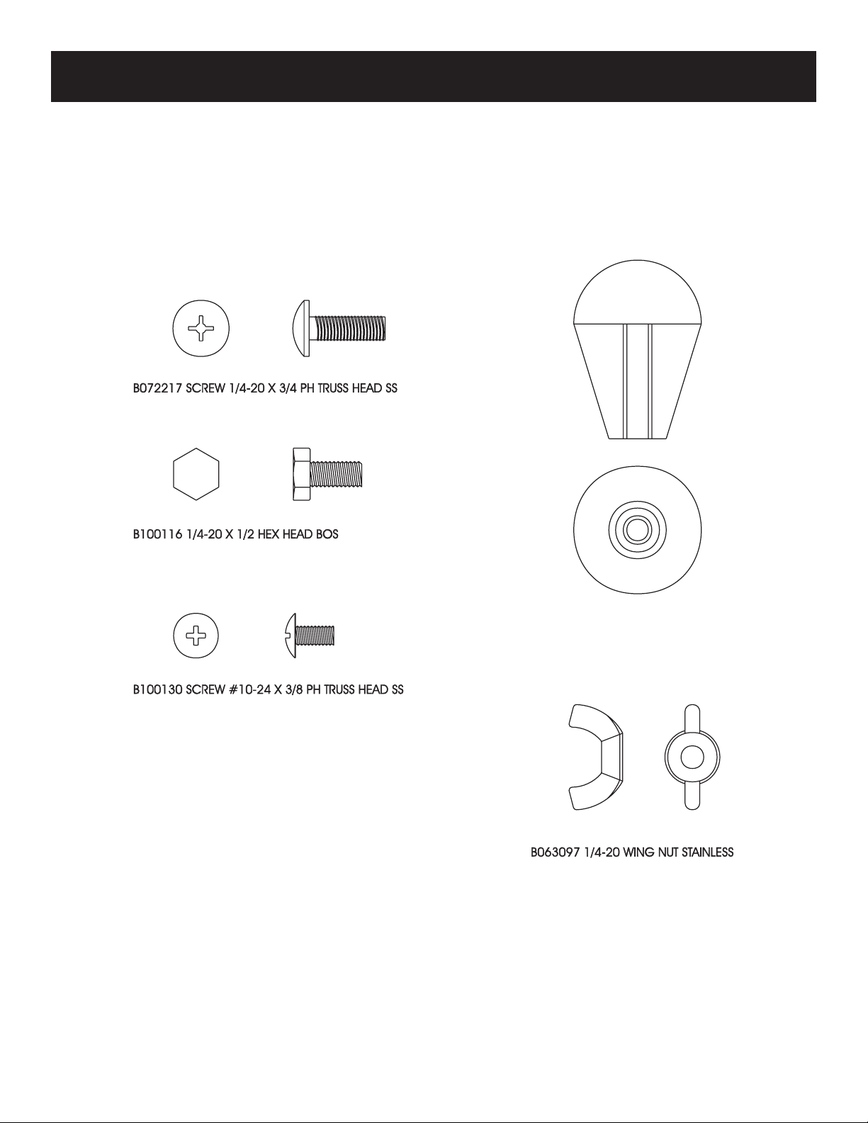
PC HARDWARE PACKAGE
B062998 KNOB
Page 4 B100999-2-0807
Page 5

DC HARDWARE PACKAGE
B072220 SCREW 1/4-20 X 3/4 PH TRUSS HEAD BOS
B100116 1/4-20 X ½ HEX HEAD BOS
B100137 SCREW #10-24 X 3/8 PH TRUSS HEAD BOS
B062998 KNOB
B072181 1/4-20 WING
NUT BOS
Page 5B100999-2-0807
Page 6

CART EXPLODED VIEW
1
2
3
4
5
6
7
8
9
9
10
10
REMOVE PROTECTIVE COATING AND VERIFY THAT ALL PARTS LISTED ON THE EXPLODED VIEW OF THIS
MANUAL HAVE BEEN INCLUDED BEFORE BEGINNING ASSEMBLY.
C
AUTION: USE CAUTION WHEN HANDLING PARTS, AS THEY MAY CONTAIN SHARP EDGES.
W
ORK GLOVES ARE RECOMMENDED TO PREVENT INJURY.
OOLS REQUIRED: PHILLIPS HEAD SCREW DRIVER (AN ELECTRIC SCREW DRIVER OR DRILL IS
T
Page 6 B100999-2-0807
RECOMMENDED TO EASE INSTALLATION.)
Page 7

CART PARTS LIST
All repair part orders should be placed through your local Broilmaster® dealer. To locate a dealer
in your area, contact Broilmaster Customer Service at 800-851-3153 • www.broilmaster.com. To
ensure prompt and accurate service, please provide the following information when placing a
repair part order: Model Number, Part Name, Part Number, and Quantity of parts needed.
KEY NO. PART NAME PC2CART DC2CART
1 KNOB B062998 B062998
2 DRIP PAN DRAWER ASSEMBLY B072205 B072210
3 CYLINDER RETAINER B064791 B064791
4 BRACE REAR CART B072201 B072203
5 DRIP PAN BRACKET B072215 B072215
6 BASE BODY ASSEMBLY B100996 B101009
7 CONTROL HOUSING B101157 B101156
8 BASE SHELF ASSEMBLY B101001 (INCLUDES 9 & 10) B101004 (INCLUDES 9 & 10)
9 CASTER W/O BRAKE B063103 B063103
10 CASTER W/BRAKE B063104 B063104
NS DRIP PAN B060337 B060337
Page 7B100999-2-0807
Page 8

CART ASSEMBLY
Attention: Peel protective film from all parts
before assembly.
Caution: Be careful when handling parts, as they
may contain sharp edges. Work gloves are recom
mended to prevent injury.
FIGURE 2
2
Attach drip pan bracket (5) to the rear brace of the base body
assembly with two 1/4-20 x 3/4 phillips head screws and two
1/4-20 Wing Nuts. Figure 2.
-
In each illustration parts are identified with "Key" num
bers. Key numbers appear in parenthesis after a part
name is mentioned for the first time in the instructions
and are labeled on the illustrations. You can reference
each part by its key number on the Parts List if you need
help in identifying a part.
Attention: For fixed base installation instruc
tions, turn to page 10.
-
1
Attach base body assembly (6) to base shelf assembly (8)
with six 1/4-20 x 3/4" phillips head screws. Insert screws
into the factory installed threaded inserts on the base shelf
assembly. Tighten screws completely. See Figure 1.
-
(Base body removed for clarity)
FIGURE 2
3
Install one 1/4-20 x 3/4 phillips head screw into the factory
installed nut on the Left Side of cart. Figure 3.
4
Fasten the Cylinder Retainer (3) to the screw with a wing nut.
Adjust height to accommodate your LP cylinder. Figure 3.
FIGURE 1
Page 8 B100999-2-0807
FIGURE 3
Page 9

CART ASSEMBLY
5
Using four 1/4-20 x 3/4 screws, fasten the grill to the
cart. Figure 4.
Note: To ease assembly you may wish to install the ig
niter as shown in your Broilmaster
attaching the grill to the cart.
®
grill manual before
FIGURE 4
6
Install one 1/4-20 x 1/2 hex head BOS into drip pan
drawer assembly (2) and tighten knob (1). Figure 5.
7
Slide the mounting tabs on the control (7) housing behind the opening on the cart. Figure 6.
-
FIGURE 6
8
For "P" series head installation, align the holes in
the front of cart with the two upper nuts on the control
housing (with the mounting tabs positioned inside
cart) and attach with the two 10-24 x 3/8 phillips head
screws. Figure 6.
For "T" series head installation, align the holes in
the front of cart with the two lower nuts on the control
housing (with the mounting tabs positioned inside
cart) and attach with the two 10-24 x 3/8 phillips head
screws. Figure 6.
FIGURE 5
9
Place the drip pan in the drip pan drawer and slide onto
drip pan bracket. Figure 7.
FIGURE 7
Page 9B100999-2-0807
Page 10

FIXED BASE INSTALLATION INSTRUCTIONS
Attention: Peel protective film from all parts
before assembly.
Caution: Be careful when handling parts, as they
may contain sharp edges. Work gloves are recom
mended to prevent injury.
In each illustration parts are identified with "Key" num
bers. Key numbers appear in parenthesis after a part
name is mentioned for the first time in the instructions
and are labeled on the illustrations. You can reference
each part by its key number on the Parts List if you need
help in identifying a part.
1
Remove four casters (9, 10) (wheels) from base shelf
assembly (8).
2
Attach base body assembly (6) to base shelf assembly
(8) with six 1/4-20x3/4" phillips head screws. Insert
screws into the factory installed threaded inserts on
the base shelf assembly. Tighten screws completely.
Figure 8.
4
Attach base to surface (deck, concrete, etc.) with four
appropriate bolts (not supplied). Figure 9.
-
-
FIGURE 9
3
Position base at the installation location.
5
Attach drip pan bracket (5) to the rear brace of the base
body assembly with two 1/4-20 x 3/4 phillips head screws
and two 1/4-20 Wing Nuts. Figure 10.
(Base body removed for clarity)
FIGURE 10
FIGURE 8
Page 10 B100999-2-0807
Page 11

FIXED BASE INSTALLATION INSTRUCTIONS
6
Install one 1/4-20 x 3/4 phillips head screw into the factory installed nut on the Left Side of cart. Figure 11.
7
Fasten the Cylinder Retainer (3) to the screw with a
wing nut. Adjust height to accommodate your LP cyl
inder. Figure 11.
9
Install one 1/4-20 x 1/2 hex head BOS into drip pan
drawer assembly (2) and tighten knob (1). Figure 13.
-
F
IGURE 13
10
Slide the mounting tabs on the control housing (7) behind the opening on cart. Allow the control housing to
rest at bottom of opening on cart. Figure 14.
FIGURE 11
8
Using four 1/4-20 x 3/4 screws, fasten the grill to the
cart. Figure 12.
Note: To ease assembly you may wish to install the
igniter as shown in your Broilmaster
attaching the grill to the cart.
®
grill manual before
11
For "P" series head installation, align the holes in
the front of cart with the two upper nuts on the control
housing (with the mounting tabs positioned inside cart)
and attach with the two 10-24 x 3/8 phillips head screws.
Figure 14.
For "T" series head installation, align the holes in
the front of cart with the two lower nuts on the control
housing (with the mounting tabs positioned inside cart)
and attach with the two 10-24 x 3/8 phillips head screws.
Figure 14.
FIGURE 12
IGURE 14
F
Page 11B100999-2-0807
Page 12

FIXED BASE INSTALLATION INSTRUCTIONS
12
Place the drip pan in the drip pan drawer and slide onto
drip pan bracket. Figure 15.
FIGURE 15
BROILMASTER
A Division of Empire Comfort Systems, Inc.
918 Freeburg Ave.
Belleville, Illinois 62220
Phone: 1-800-851-3153
FAX: 1-800-443-8648
V
ISIT OUR WEB SITE AT WWW.broilmaster.com
®
RETAIN OWNER’S MANUAL FOR FUTURE REFERENCE.
FORM NO. B100999-0-0906
Page 12 B100999-2-0807
 Loading...