

PLEASE RECORD YOUR MODEL
-
-
dd mm yyyy
BUILT-IN GAS GRILL
OWNER’S MANU AL
ANSI Z21.58-2015 / CSA 1.6-2015
CONTENTS
SAFETY .............................................................................. 2
INSTALLATION .................................................................. 2
LP GAS CYLINDER ............................................................ 10
HOSE & REGULATOR ....................................................... 11
NATURAL GAS .................................................................. 12
GAS SUPPLY HOSE ......................................................... 12
LEAK TESTING.................................................................. 13
VENTURI TUBES ............................................................... 14
LIGHTING ........................................................................... 15
OPERATION ....................................................................... 16
COOKING TECHNIQUES ...................................................... 17
MAINTENANCE ................................................................. 20
TROUBLESHOOTING ....................................................... 21
WARRANTY ....................................................................... 22
MANUEL DE L’UTILISATEUR .......................................... 23
MANUAL DEL USUARIO ................................................... 45
NOTE TO INSTALLER: THESE INSTRUCTIONS MUST BE
LEFT WITH THE CONSUMER. .
DANGER
IF YOU SMELL GAS:
1. SHUT OFF GAS TO THE APPLIANCE
2. EXTINGUISH ANY OPEN FLAME
3. OPEN LID
4. IF ODOR CONTINUES, KEEP AWAY FROM
THE APPLIANCE AND IMMEDIATELY CALL
YOUR GAS SUPPLIER OR YOUR FIRE
DEPARTMENT
WARNING
1. DO NOT STORE OR USE GASOLINE OR
OTHER FLAMMABLE LIQUIDS OR
VAPORS IN THE VICINITY OF
THIS APPLIANCE
2. AN LP CYLINDER NOT CONNECTED FOR
USE SHALL NOT BE STORED IN THE
VICINITY OF THIS OR ANY OTHER
APPLIANCE
NUMBER, SERIAL NUMBER AND DATE
OF PURCHASE HERE.
This information can be found on the black and silver OMC caution sticker
located in the grease drawer of your gas grill.
Model Number
Serial Number
Date of Purchase / /
READ ALL INSTRUCTIONS CAREFULLY BEFORE OPERATING YOUR GAS
RETAIN THESE INSTRUCTIONS FOR FUTURE
REFERENCE.
GRILL.
FOR ASSEMBLY INSTRUCTION, PLEASE SEE YOUR ASSEMBLY MANUAL
OR VISIT www.omcbbq.com TO VIEW OUR ASSEMBLY
VIDEO
1-800-265-2150 EN
info@omcbbq.com
70094-40 REV A 08/17
SAFETY INSTALLATION
In
the
Your Broil King® built-in gas grill is a safe, convenient
appliance when assembled, installed and used properly.
As with all gas-fired products, however, certain safeguards
must be observed. Failure to follow these safeguards
may result in serious injury or damage. If you have
questions concerning assembly, installation or operation,
consult your dealer, gas appliance specialist, Gas Company
or our direct customer service line at 1-800-265-2150 /
info@omcbbq.com
CAUTION
• FOR OUTDOOR USE ONLY
• THIS APPLIANCE MUST NOT BE OPERATED
UNATTENDED
• SPECIAL CARE MUST BE TAKEN TO KEEP SMALL
CHILDREN AWAY FROM HEATED SURFACES
Use caution when handling or transporting this
product. Metal edges can be hazardous. Use
appropriate gloves when lifting or handling.
ELECTRICAL CAUTION
1. If any accessory is used on this appliance that
requires an external electrical power source, the
accessory when installed must be electrically grounded
in accordance with local codes. In the absence of local
codes, the following standards apply:
(U.S.A.) ANSI/NFPA No. 70-Latest Edition and
(Canada) CSA C22.1 Canadian Electrical Code
2. Do not cut or remove the grounding prong from the
plug.
3. Keep the electrical supply cord and fuel supply hose
away from any heated surface.
WARNING
This product can expose you to chemicals including lead,
which is known to the state of California to cause cancer,
birth defects or other reproductive harm. Wash your hands
after handling this product.
The burning of gas cooking fuel can expose you to
chemicals including Carbon Monoxide, which is known to
the state of California to cause cancer, birth defects or other
reproductive harm. To minimize exposure to these
substances, always operate this unit according to the
owner’s manual, ensuring you provide good ventilation
when cooking with gas.
FOR MORE INFORMATION GO TO
WWW.P65WARNINGS.CA.GOV
1.
ANSI Z223.1/NFPA 54 - Latest Edition National Fuel
Gas Code and Latest Local Codes where Applicable
2. In Canada, this appliance must be installed in
CSA-B149.1 Natural Gas and Propane Installation
Code
3. DO NOT restrict the flow of air to the appliance.
4. Keep the area surrounding the appliance free of
5. This appliance is not intended to be installed in, or
U.S.A.,
accordance with the local code and the rele va nt
national code:
accordance with the local code and the rele va nt CSA
standards:
combustible materials, gasoline, and all flammable
liquids and vapors.
on, recreational vehicles and/or boats.
CONFIGURATION OPTIONS
The built-in grill and all other accessory units should be on
site before construction begins.
There are many options for designing your Outdoor
Kitchen.
If the grill includes a Side Burner, remember to position the
Side Burner to the left of the grill.
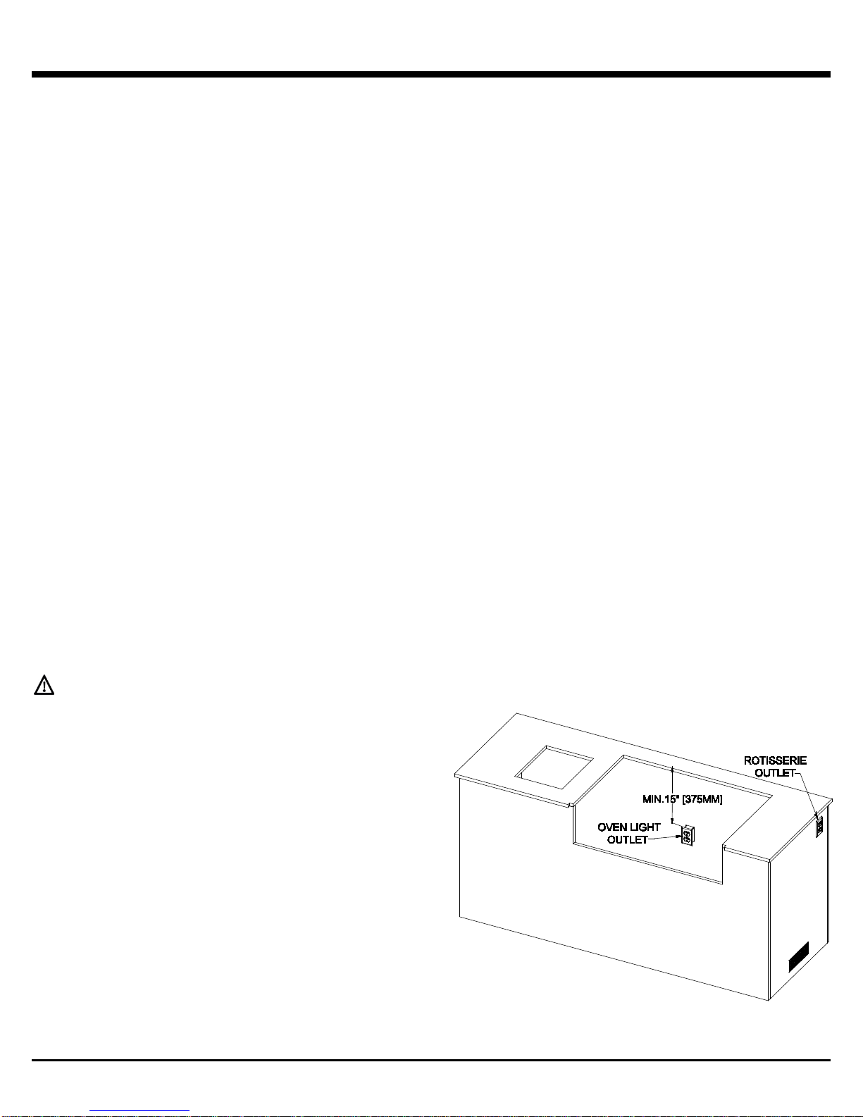
ELECTRICAL OUTLETS
If a Rotisserie will be used, an electrical outlet for the
Rotisserie should be positioned on the rear right side of the
grill.
If internal lights are provided, a Ground Fault Interrupt (GFI)
electrical outlet for the lights should be positioned inside the
enclosure on the rear wall 15 inches (38cm) below the
countertop.
this appliance
must
be installed in
2
INSTALLATION
The installation should be done b y a qualified professional.
POSITIONING YOUR GAS GRILL
Ensure there is adequate ventilation for heat and smoke to
dissipate.
WHEN DETERMINING THE POSITION OF THE GRILL,
GIVE THOUGHT TO:
• Exposure to wind
• Proximity to traffic
• Keeping gas lines and electrical connections as short as
possible and away from heat sources
LOCATE THE GRILL:
• To provide enough room to safely evacuate the area in
the event of a fire
• In a well ventilated area
NEVER LOCATE THE GRILL:
• In a garage, breezeway or shed, or any other enclosed
area
• Under overhead unprotected combustible construction
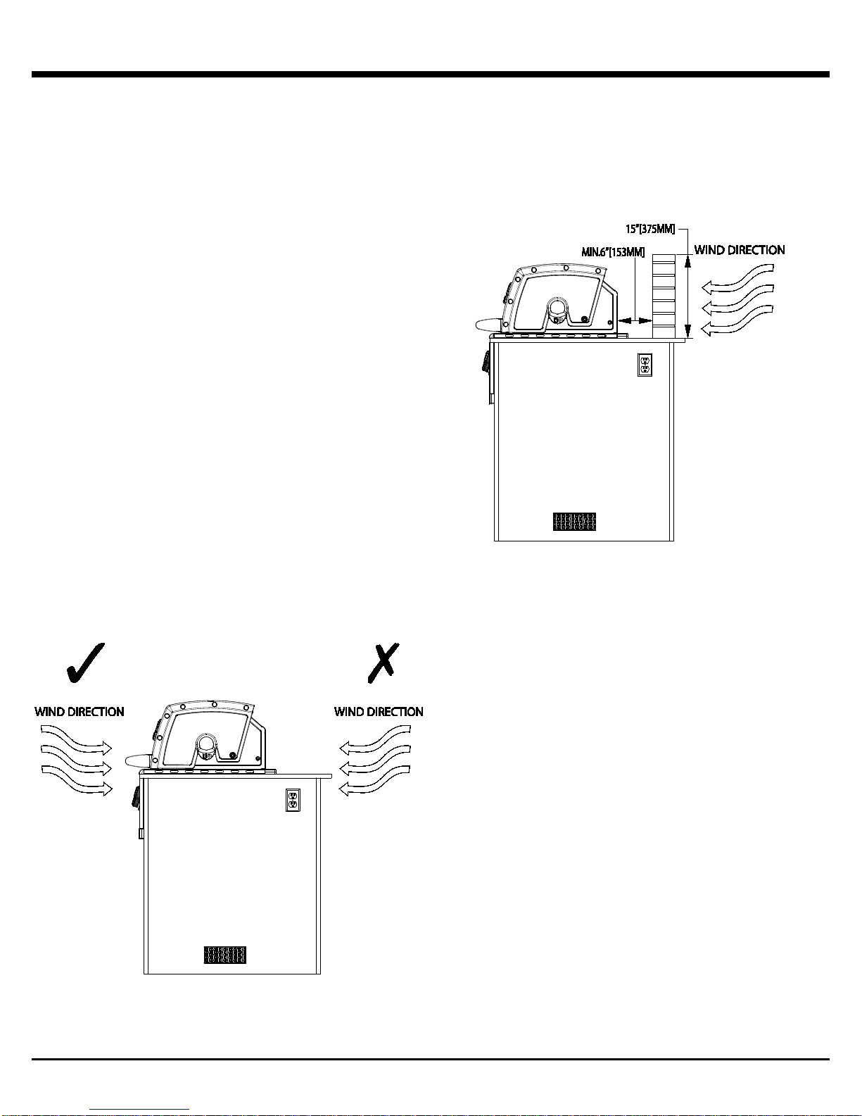
The grill is designed to take air in through the control panel
area and send the exhaust products out through the exhaust
gap at the rear of the hood.
If locating the grill in a windy area, locate the grill so the
prevailing wind will blow air at the front of the grill. A light
wind blowing at the front of the grill will:
• Assist the grill in venting hot air thru the back of the grill
• Assist in keeping smoke from blowing at someone who
is cooking on the grill
If the grill is located where the prevailing wind is blowing at
the rear of the grill, a windbreak will need to be installed.
The windbreak should be constructed to prevent wind from
entering the exhaust vent in the rear of the grill and comply
with the clearances specified for combustible or noncombustible construction as outlined in these instructions.
WARNING: Wind blowing in the back of the gril l or along
the exhaust vent can disrupt the proper flow of air
though the grill, leading to reduced performance, or in
certain cases, cause excess heat buildup in the control
panel area. This can lead to a burn hazard if the control
panel surface and knobs become too hot to touch.
During high wind conditions, it is best not to use the grill.
Damage to the grill resulting from use in windy conditions,
such as melted knobs or igniter wires, or valve panel
discoloration from heat build-up, are excluded from warranty
coverage.
3
INSTALLATION - CLEARANCES
SIDE AND REAR WALL CLEARANCES
NOTE: Installation requires a non-combustible
countertop surface. The countertop surface must be
constructed from solid materials and must be level and
smooth.
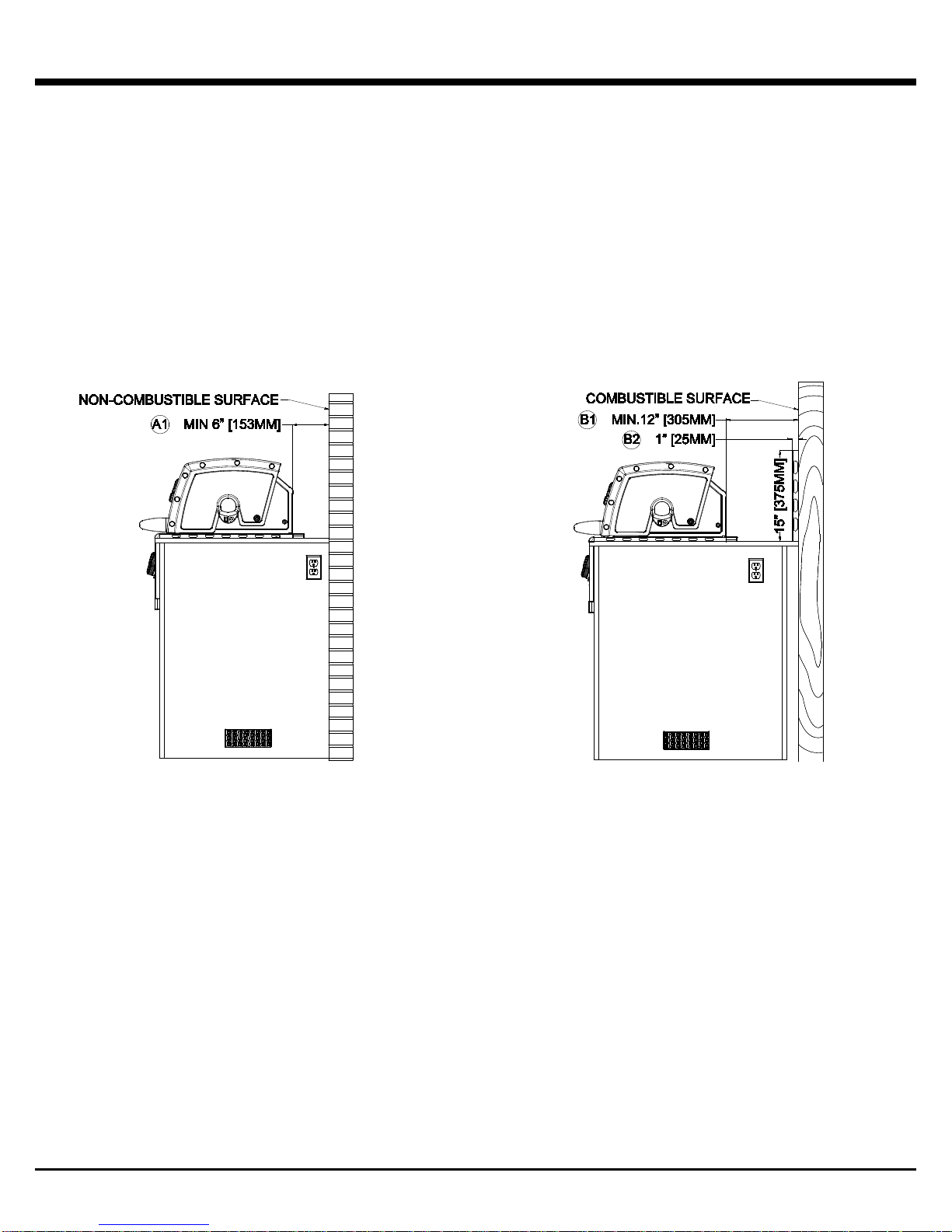
A) Clearance between grill and non-combustible wall
above the counter top surface
1. The grill must have a minimum of 6” [153mm] right, left
and rear clearance from any non-combustible wall to
allow for proper ventilation and space for lid to open
completely.
DEFINITION OF COMBUSTIBLE MATERIAL
Any building structure or decorative structure made of
wood, compressed paper, plant fibers, vinyl/plastic or other
materials that are capable of transferring heat or being
ignited and burned. Such material shall be considered
combustible even though flame-proofed, fire-retardant
treated or surface-painted, or plastered.
DEFINITION OF NON-COMBUSTIBLE
MATERIAL
Material which is not capable of being ignited and burned,
such as materials consisting entirely of, or a combination
of, steel, iron, brick tile, concrete, slate, and plaster.
B) Clearance between grill and a protected
combustible wall above the counter top surface
1. The grill must have a minimum of 12” [305mm] right,
left, and rear clearance from the protected combustible
wall.
2. A protected combustible wall has a 1” (25mm)
ventilated space between a non-combustible surface
and the combustible surface extending 15” (375mm)
from the counter top surface.
4
INSTALLATION - CLEARANCES
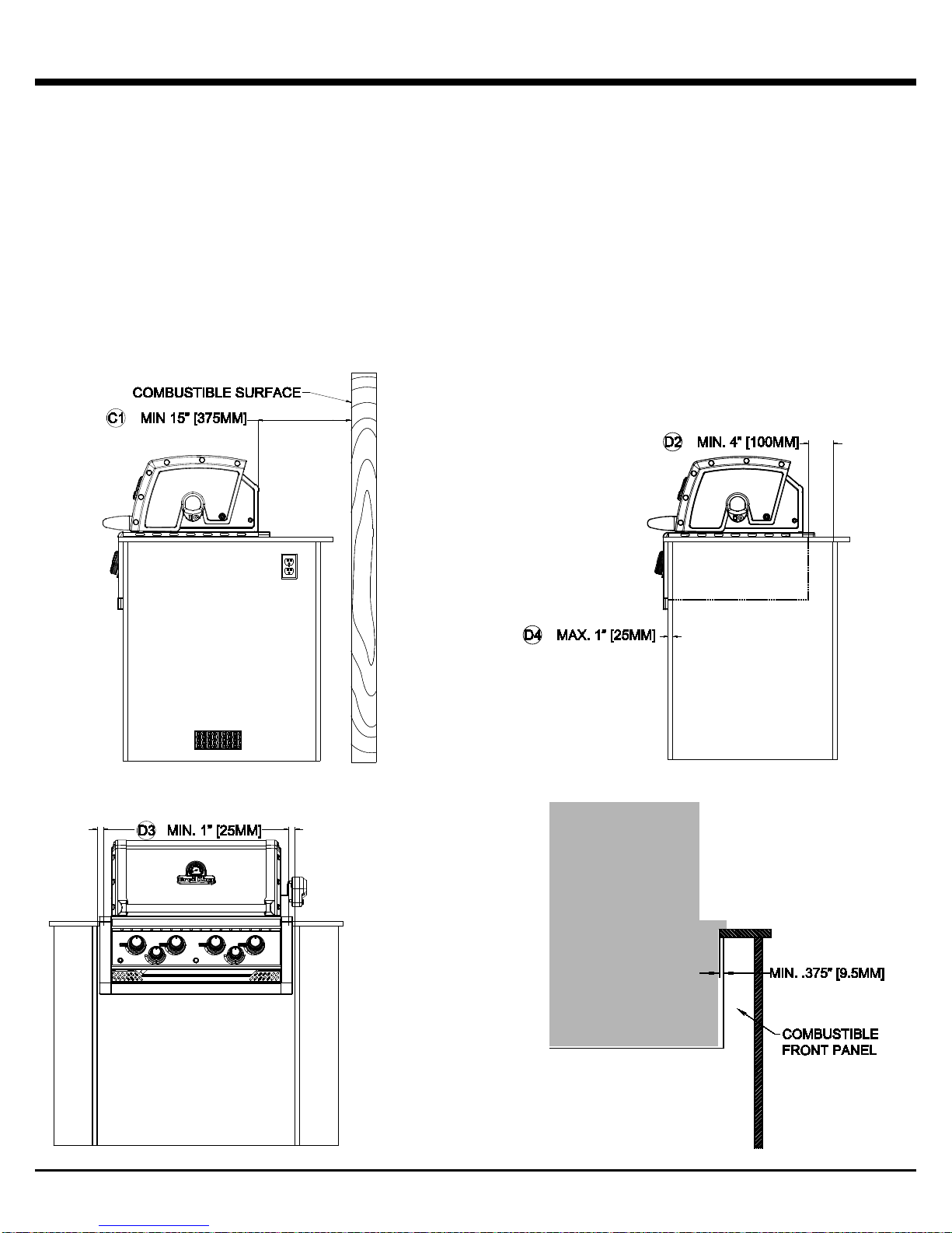
C) Clearance between grill and combustible wall
above the counter top surface
1. The grill must have a minimum of 15” [375mm] right,
left, and rear clearance from any combustible wall
above the non-combustible counter top surface.
D) Clearance between the grill and combustible or
non-combustible construction below the counter
top surface .
1. “0” clearance is required below the counter top to noncombustible construction.
2. 4” (100) mm clearance is required below the countertop
to combustible construction to the rear.
3. 1” (25) mm clearance is required be lo w the count er top
to combustible construction to the left and right sides.
4. 3/8” (9.5mm) clearance is required below the
countertop to a combustible front wall of the enclosure
provided the front wall of the enclosure is less than 1”
(25) mm thick.
5
INSTALLATION - CLEARANCES
WARNING: Do not install or use the grill under
unprotected combustible construction without a fire
safe ventilation system.
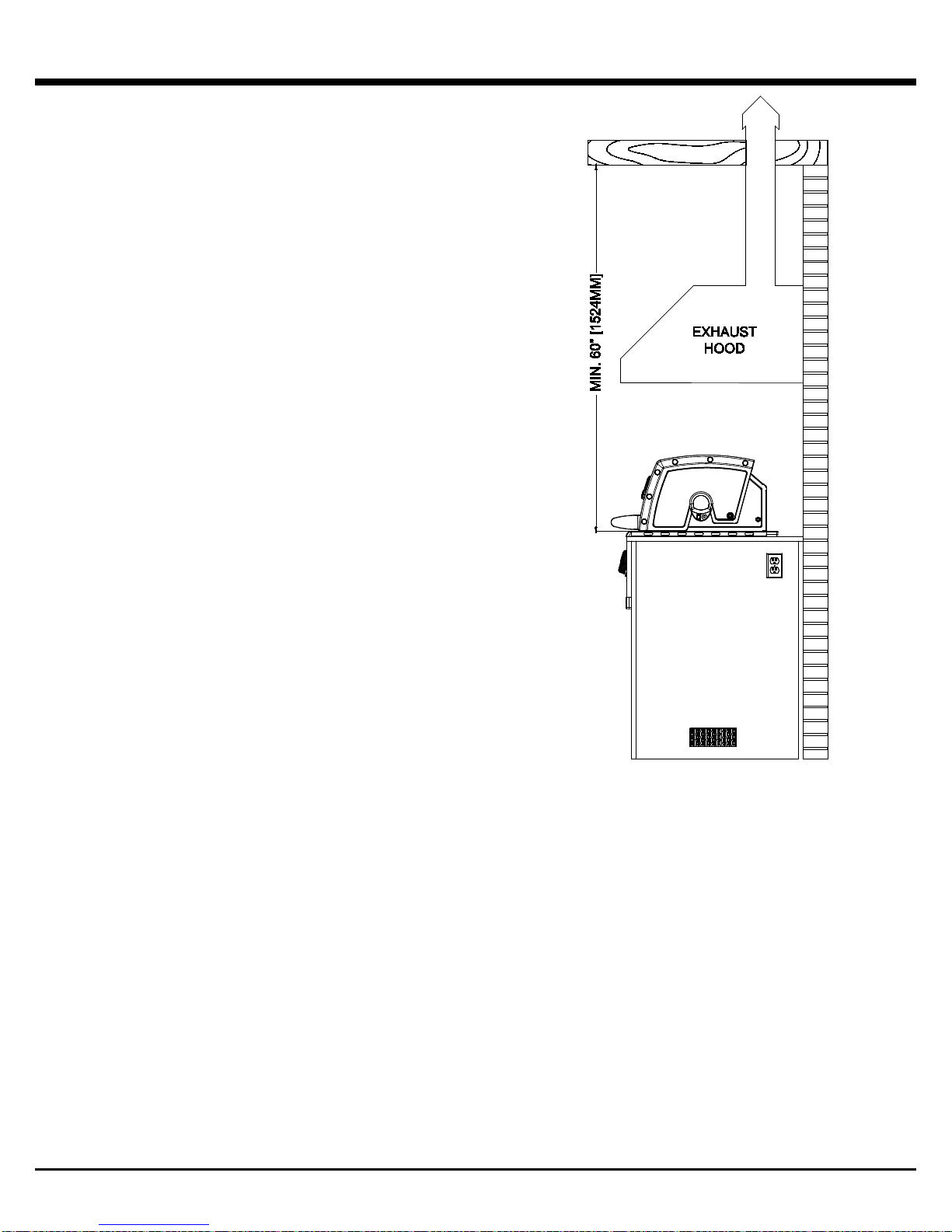
OVERHEAD CONSTRUCTION AND
EXHAUST HOOD REQUIREMENTS
A minimum 60” [1524mm] clearance is required between
the grilling surface and the overhead construction.
When installed under combustible overhead construction,
the area above the cooking surface of the grill must be
covered with an exhaust hood. The exhaust h ood pr ov ides
the protection for the combustible overhead construction.
When installed under overhead non-combustible
construction, an exhaust hood is highly recommended.
EXHAUST HOOD
When using an exhaust hood, the area above the cooking
surface of the grill must be covered with a hood larger than
the cooking area of the grill, and with a minimum of
1200CFM (cubic feet per minute) for proper outdoor
application.
6
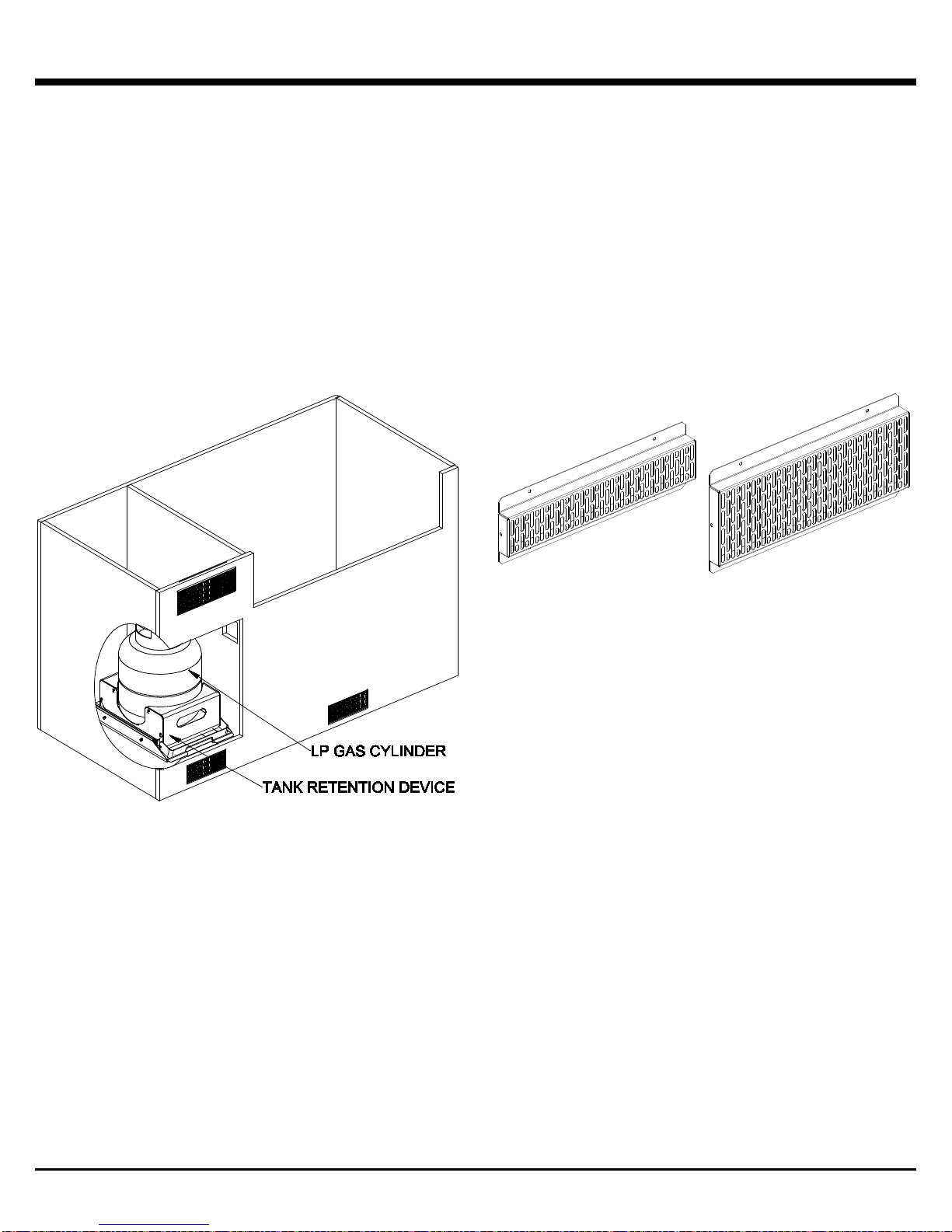
INSTALLATION - ENCLOSURES
ENCLOSURES FOR THE GRILL AND LP
GAS CYLINDER
Grill and LP Gas Cylinder enclosures must meet the
requirements for venting, cylinder retention, and separation of
the LP gas cylinder from a heat source as outlined in the
ANSI Standard for Outdoor Cooking Gas Appliances,
Z21.58/CSA 1.6 for LP enclosures.
There are 2 types of enclosures:
1. Grill enclosure without an LP gas cylinder.
2. Grill enclosure with an LP gas cylinder.
WARNING: Do not store a spare cylinder in an enclosure .
Enclosures for LP gas cylinders must be fitted with a cylinder
retention device. A Broil King® cylinder retention device is
available from your dealer.
WARNING: Vents are required in the enclosures to
provide ventilation in the event of a gas leak.
Ventilation reduces moisture and provides cooling in the
enclosures.
Note: The drawings are for reference only.
• Each vent shall have minimum openings to allow the
entrance of a 1/8” (3.2mm) diameter rod
• Make sure the vents are not blocked by interior supports.
• Keep vents clean and clear of obstructions
• Vent(s) can be located in low visibility areas and sh ou l d
be protected by screens to prevent rodents and insects
from entering the enclosure
• Vents that provide a minimum free area of 10 square
inches (65 square cm) and vents that provide a minimum
free area of 20 square inches (130 square cm) are
available from your dealer
• Gas supply shut off valves must be readily acces s ible for
hand operation
• A door on the enclosure to gain access to the cylinder
valve is acceptable provided it is non-locking and can be
opened without the use of tools
• A minimum clearance of 2 inches (51mm) is required
between the floor of an lp gas cylinder enclosure and the
ground
• If a gas leak should occur or the lp gas cylinder should
vent in the lp gas cylinder enclosure, the gas should not
be allowed to vent or migrate into empty or “hollow” areas
of the enclosure
WARNING: Ventilation openings should only
communicate with the outside of the enc losure, so that
the gas can dissipate outside of the enclosure.
7
INSTALLATION - ENCLOSURES
GRILL ENCLOSURE DIMENSIONS
420 / 490
590
XL
A
MIN
30 5/16” [770mm]
36 11/16” [932mm]
44” [1118mm]
MAX
30 15/32” [774mm]
36 27/32” [936mm]
44 5/32” [1122mm]
B
MIN
31 3/8" [797mm]
37 3/4" [959mm]
45 1/8" [1146mm]
C
MIN
27” [686mm] with surface mount GFCI receptacle
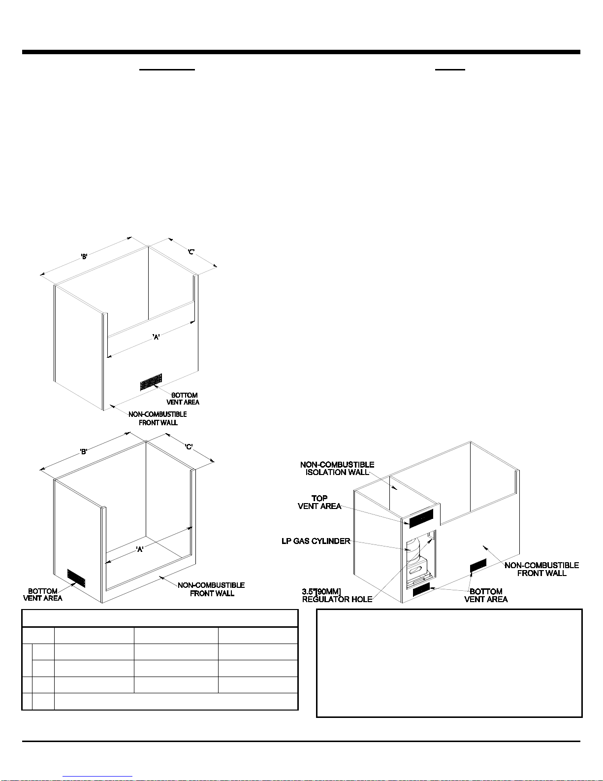
GRILL ENCLOSURE WITHOUT AN LP GAS
CYLINDER
• Ventilation totaling a minimum free area of 10 square
inches (65 square cm) is provided at the top of the grill
through the side trim and rear trim of the grill
• Ventilation totaling a minimum free area of 5 square
inches (13 square cm) is provided at the bottom of the
grill through the bottom trim of the grill
• Ventilation totaling a minimum free area of 10 square
inches (33 square cm) is required at the bottom of the
enclosure
• Position the bottom edge of vent 1” (25mm) or less
from the floor level and within 5” (127mm) of the bottom
of the enclosure
• Be careful not to obstruct these vents
GRILL ENCLOSURE WITH AN LP GAS
CYLINDER
• A remote LP gas cylinder enclosure is required for
installations that use an LP gas cylinder
• Construct enclosure with four sides, a top and a bottom
with minimum inside dimensions of:
o height – 20” (50cm)
o width – 15” (38.5cm)
o depth – 14” (36cm)
• Enclosure must not allow space for a spare tank to be
stored inside the enclosure
• Ventilation totaling a minimum free area of 20 square
inches (130 square cm) is required at the top on the
exposed exterior wall of the enclosure. (As per ANSI
Standard Z21.58/CSA 1.6)
• Ventilation totaling a minimum free area of 10 square
inches (65 square cm) is required at the bottom on the
exposed exterior wall of the enclosure. (As per ANSI
Standard Z21.58/CSA 1.6)
• Position the top vent(s) within 5” (127mm) of the top of
the enclosure
• Position the bottom vent 1” (25mm) or less from the
floor level and within 5” (127mm) of the bottom of the
enclosure
• The remote LP gas cylinder enclosure must isolate the
LP gas cylinder from the burner compartment, so that it
provides shielding from radiation, be a flame barrier
and provide protection from foreign material such as
hot drippings
DANGER
Failure to build a remote LP gas cylinder enclosure for
a single 20 lb. LP gas cylinder only, following the
requirements for ventilation, cylinder retention and
separation of the LP gas cylinder from a heat source,
listed in the ANSI Standard for Outdoor Cooking Gas
Appliances, Z21.58/CSA 1.6, could be dangerous, and
result in a fire or an explosion causing ser ious bodily
injury or death and damage to property.
8
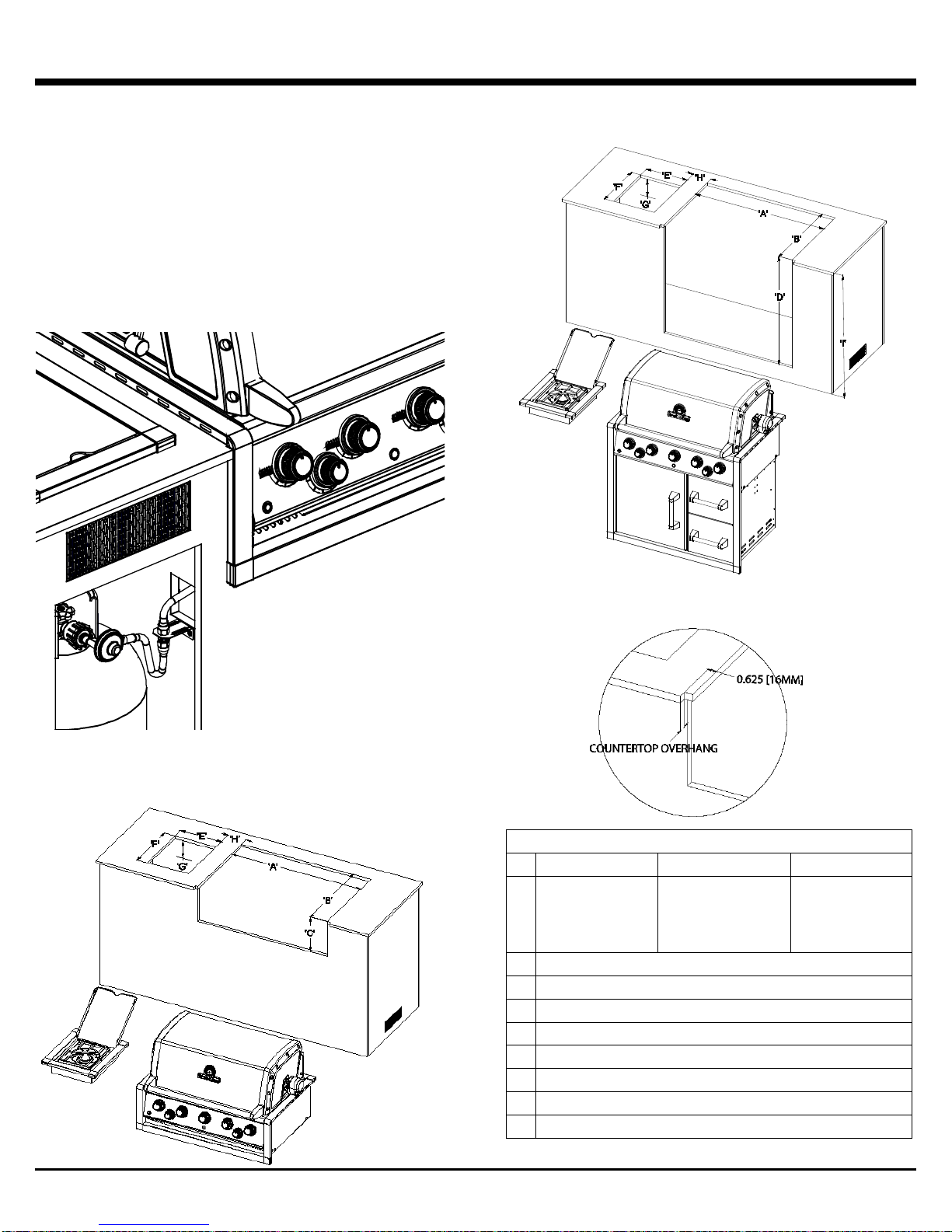
INSTALLATION – CUT OUT DIMENSIONS
ISLAND CUTOUT DIMENSIONS
490
590
XL
A
MIN. 297/8"
[765mm]
MIN. 361/4"
[927mm]
MIN. 435/8"
[1115mm]
B
MIN. 231/8" [590mm] – MAX. 233/8” [595mm]
C
MIN. 1029/32" [280mm] – MAX. 111/8” [285mm]
D
MIN. 311/2" [800mm] – MAX. 313/4” [810mm]
E
MIN. 111/2" [290mm] – MAX. 113/4” [300mm]
F
MIN. 141/2" [370mm] – MAX. 143/4” [375mm
G
MINIMUM 41/2" [115mm]
H
MINIMUM 3” [75mm] – MAXIMUM 7” [180mm]
I
MINIMUM 34” [865mm]
SPECIFICATION FOR CONNECTING TO A 20
lb. LP GAS CYLINDER
• A 14” (356 mm) corrugated hose with a 3/8” SAE 45
degree fitting is connected to the manifold of the grill
• Do not use pipe sealant on the 3/8” SAE 45 degree
fitting
• The 3/8” SAE 45 degree fitting must be firmly attached
to rigid permanent construction
• If you choose to use a corrugated gas hose other than
the one supplied, the connector must comply with the
Standard for Connectors for Gas Appliances, ANSI
Z21.24 ● CSA 6.10
COUNTERTOP CUT OUT DIMENSIONS –
BUILT-IN
COUNTERTOP CUT OUT DIMENSIONS –
BUILT-IN WITH CABINET
COUNTER TOP NOTCH DETAIL
[758mm]
MAX. 301/8”
9
[920mm]
MAX. 361/2”
[1108mm]
MAX.437/8”
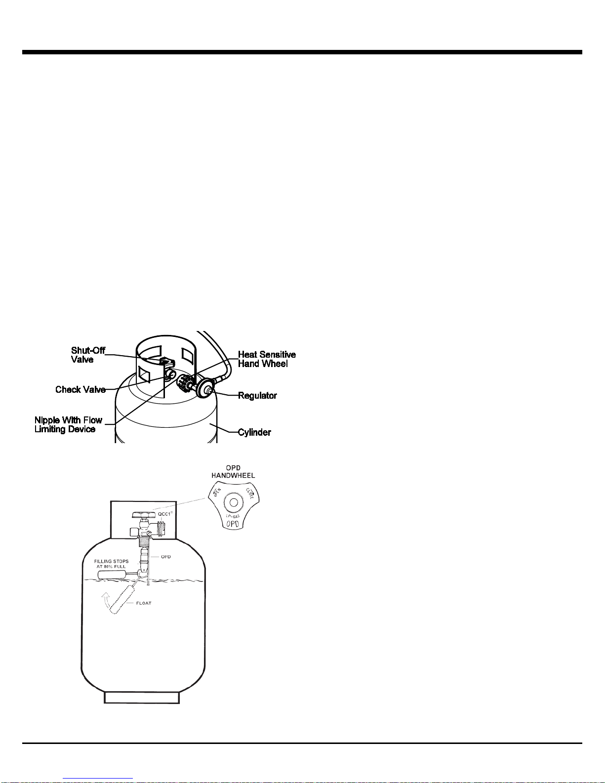
LP GAS CYLINDER
The standard for outdoor gas appliances, ANSI Z21.58/
CAN/CGA-1.6, requires that LP gas cylinders used with LP
gas appliances be equipped with both
• An Overfill Prevention Device (OPD)
• A QCC®-1 Quick Closing Coupling system
OVERFILL PREVENTION DEVICE
The OPD is designed to reduce the potential of over filling
propane cylinders, thus reducing the possibility of relief valve
discharges of raw propane. The OPD causes a slower
purge/fill operation.
QCC®-1 QUICK CLOSING COUPLING
The QCC®-1 system incorporates safety features required by
the American National Standards Institute (ANSI) and the
Canadian Standards Association (CSA).
• Gas will not flow until a positive connection has been
made
• A thermal element will shut off the flow of gas between
240° and 300° F
• When activated, a Flow Limiting Device will limit the flow
of gas to 10 cubic feet / hour
The LP gas cylinder is not included with the Gas Grill.
Be sure to use an LP gas cylinder equipped with the OPD
and the QCC® valve.
IDENTIFICATION
The QCC®-1 valve is recognized by the external threads on
the inlet port of the LP gas cylinder valve.
The OPD hand wh ee l has been standardized to the shape
shown.
QCC® /OPD equipped LP gas cylinders are available from
your Gas Grill Dealer.
NOTE: Any attempt to connect the regulator, by use of
adapters or any other means, to any other valve could
result in damage, fire or injury and may negate the
important safety features in the QCC®-1 system.
SPECIFICATION
1. All LP gas cylinders used with this appliance must be
constructed and marked in accordance with the
Specifications for LP gas cylinders of the U.S.
Department of Transportation (D.O.T.) or the National
Standard of Canada, CAN/CSA-B339, Cylinders, Spheres
and Tubes for Transportation of Dangerous Goods ; and
Commission, as applicable.
2. The LP gas cylinder used for this appliance must not
have a capacity exceeding 20 lb. (9 kg). Approximately
18” (46cm) high and 12” (31cm) diameter.
3. All LP gas cylinders used with this appliance should be
inspected at every filling and re qualified by a licensed
service outlet at the expiry date (10 years), in accordance
with the DOT (USA) and Canadian Transport
Commission (Canada) codes for LP Gas Cylinders.
4. All LP gas cylinders used with this appliance must be
provided with a shutoff valve terminating in a cylinder
valve outlet No. 510, specified in the Standard for
Compressed Gas Cylinder Valve Outlet and Inlet
Connection (USA) ANSI/CGA-V-1-1977 (Canada) CSA
B96.
5. The LP gas cylinder supply system must be arranged for
vapor withdrawal.
6. The LP gas cylinder must include a collar to protect the
cylinder valve.
7. The LP gas cylinder must be installed as per assembly
instructions.
8. Never fill the LP gas cylinder beyond 80% full. A fire
causing death or serious injury may occur.
9. The LP gas cylinder valve must include a safety relief
device having direct communication with the vapor space
of the cylinder.
10

LP GAS CYLINDER HOSE & REGULATOR
HANDLING
1. Government regulations prohibit shipping full LP gas
cylinders. You must take your new cylinder to a LP gas
dealer for filling.
2. A filled LP gas cylinder is under very high pressure.
Always handle carefully and transport in the upright
position. Protect the valve from accidental damage.
3. Do not tip the LP gas cylinder while connecting it to the
regulator. Fasten the LP gas cylinder securely during
transport, use and storage.
4. If the LP gas cylinder is tipped after it is connected to the
regulator, shut off the gas, disconnect the regulator and
have it checked before using it again.
STORAGE
1. Store the LP gas cylinder outdoors in a well-ventilated
place.
2. Do not store the LP gas cylinder in direct sunlight, near
a source of heat or combustion.
3. Do not store a spare LP gas cylinder in an enclosure.
Disconnected cylinders must have a dust cap installed
and must not be stored in a building, garage or any
enclosed area.
4. Keep out of the reach of children.
5. When the LP gas cylinder is connected to the gas grill,
the gas grill and LP gas cylinder must be operated
outside in a properly ventilated place.
OPERATION
1. Never connect your gas grill to an LP gas cylinder
without the regulator provided, and NEVER TO AN
UNREGULATED LP GAS SUPPLY. The regulator
supplied with the barbecue must be used.
2. Always leak test the LP gas cylinder to regulator
connection when connecting the LP gas cylinder to the
appliance. See “Leak Testing” (page 13).
3. Do not operate appliance if the smell of LP gas is
present. Extinguish all flame and determine source of LP
gas leak before proceeding. Do not ignite the appliance
until the LP gas leak has been found and sealed.
4. Always shut off LP gas cylinder valve when the
appliance is not in use.
1. LP gas grills are equipped with a hose and regulator
with a QCC®-1 Quick Closing Coupling.
2. The QCC®-1 coupling contains a magnetic Flow
Limiting Devic e which will limit the flow of gas should
there be a leak between the regulator and the appliance
valve. This device will activate if the cylinder valve is
opened while the appliance valves are open. Be sure
the appliance valves are off before the cylinder
valve is opened to prevent accidental activation.
3. The QCC®-1 coupling incorporates a heat sensitive
hand wheel that will cause the back check module in the
QCC®-1 cylinder valve to close when exposed to
temperatures between 240° and 300°F. Should this occur,
do not attempt to reconnect the hand wheel. Remove
hose/regulator assembly and replace with a new one.
4. The pressure regulator is set at 11 inches WC
(water column) and is for use with LP gas only. The
hose and hose couplings comply with CGA Standard
CAN 1.83. No modifications or substitutions should be
attempted.
5. Protect the hose from dripping grease and do not
allow the hose to touch any hot surface, including the
base casting of the barbecue.
6. Inspect the seal in the QCC®-1 cylinder valve when
replacing the LP gas cylinder or once per year
whichever is more frequent. Replace the seal if there is
any indication of cracks, creases, or abrasion.
7. Inspect the hose before each use. If the hose is
cracked, cut, abraded or damaged in any way, the
appliance must not be operated.
8. For repair or replacement of the hose/regulator
assembly, contact customer service.
CONNECTION
1. Be sure LP gas cylinder valve and app li ance va l ves ar e
“OFF.”
2. Place full LP gas cylinder in LP gas cylinder well and
secure as per assembly instructions.
3. Center the nipple in the LP gas cylinder valve and hold
in place. Using other hand, turn the hand wheel clockwise
until there is a positive stop. Do not use tools. Hand
tighten only. When making the connection, hold the
regulator in a parallel with the LP gas cylinder valve,
so as not to cross thread the connection.
4. Leak test connections. See “ Leak Testing” (Pages 13).
5. Refer to lighting instructions. To avoid activating
the Flow Limiting Device when lighting, open LP gas
cylinder valve slowly with the appliance valves off. If
the Flow Limiting Device is accidentally activated, turn
off LP gas cylinder valv e and appliance valves, wait 10
seconds to allow the device to reset, open the LP gas
cylinder valve slowly, then open the appliance valve.
DISCONNECTION
Always close LP gas cylinder valve and remove coupling nut
before moving LP gas cylinder from specified operation
position.
11
INSTALLATION – FIXED PIPE LP OR NATURAL GAS LINE
GAS LINE LOCATION
LP Gas and Natural Gas supply lines should be installed by
a qualified professional.
Note: Provide access in the enclosure for gas supply and
regulator service.
Note: Area should be kept clear of sharp or abrasive
surfaces to avoid damage to gas supply lines. Exercise
caution when pulling gas lines through the built-in
enclosure.
SPECIFICATIONS FOR PIPING
• Installation must use rigid pipe, semi-rigid tubing, or a
connector complying with the Standard for Connectors
for Outdoor Gas Appliances and Manufactured Homes,
ANSI Z21.75•CSA 6.27 and suitable for outside
installation
• The gas connections must be firmly attached to rigid,
permanent construction
• A 3/8 inch SAE 45 degree flare connection has been
provided. Do not use pipe sealant on this connection
• A manual shut-off valve must be installed outdoors, and
be accessible from outside of the built in enclosure.
• For bulk propane and natural gas, an additional indoor
manual shut-off valve should be installed in the branch
fuel line in an accessible location near the supply line
CONNECTION TO A REMOTE SELF
CONTAINED LP GAS SUPPLY
• LP gas grills are designed to operate at a regulated
pressure of 11 inches water column
• An in line LP pressure regulator suitable for bulk
propane installations is required to maintain 11
inches water column pressure. (not supplied)
• The gas supply connection from the grill manifold to the
gas supply bulkhead must not exceed 72” (182cm)
• When the grill is not in use, turn off the LP gas supply
at the shut off valve
CONNECTION TO NATURAL GAS
SUPPLY
• If grill is designed for use with natural gas, do not use
with liquid propane (bottled gas). The valves, orifices,
and hoses are for natural gas only
• Natural Gas Grills are designed to operate at a
regulated pressure of 7 inches water column
• The gas supply hose from the grill manifold to the gas
supply bulkhead must not exceed 120” (305cm)
• The gas must be turned off at the natural gas supply
when the barbecue is not in use
• When the grill is not in use, turn off the natural gas
supply at the shut off valve
GAS SUPPLY TESTING
• The outdoor gas grill and its individual shutoff valve
must be disconnected from the gas supply piping
system during any pressure testing of that system at
test pressures in excess of 1/2 psig (3.5kPa)
• The outdoor gas grill must be isolated from the gas
supply piping system by closing its individual manual
shut off valve during any pressure testing of the gas
supply piping system at test pressures equal to or less
than 1/2 psig (3.5kPa)
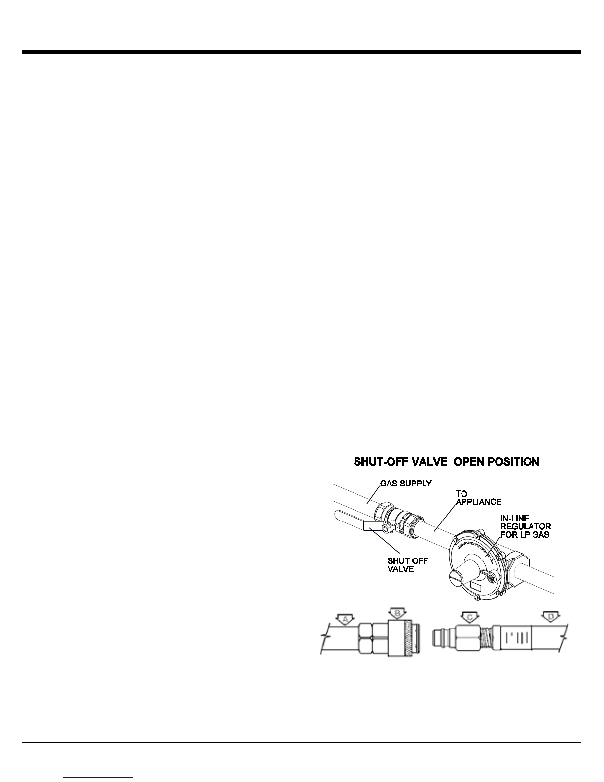
GAS SUPPLY HOSE
• On models supplied with an extension hose, the hose
assembly is specifically designed for your model. No
modifications or additions should be attempted. Hose
and hose couplings comply with CGA Standard CAN
1.83
• On models equipped with the "quick disconnect"
coupling, close "shut off valve" before disconnecting
coupling
• "Quick disconnect" coupling must be kept clean and
free of dirt and debris
• Protect the hose from dripping grease and do not allow
the hose to touch any hot surface, including the base
casting of the barbecue
• Inspect the hose at least once per year. If the hose is
cracked, cut, abraded or damaged, the appliance must
not be used
• For replacement of hose assembly, contact your
dealer or approved service center
A. GAS SUPPL Y PI PIN G
B. QUICK DISCONNECT COUPLING
C. ADAPTER FITTING
D. EXTENSION HOSE ASSEMBLY
12
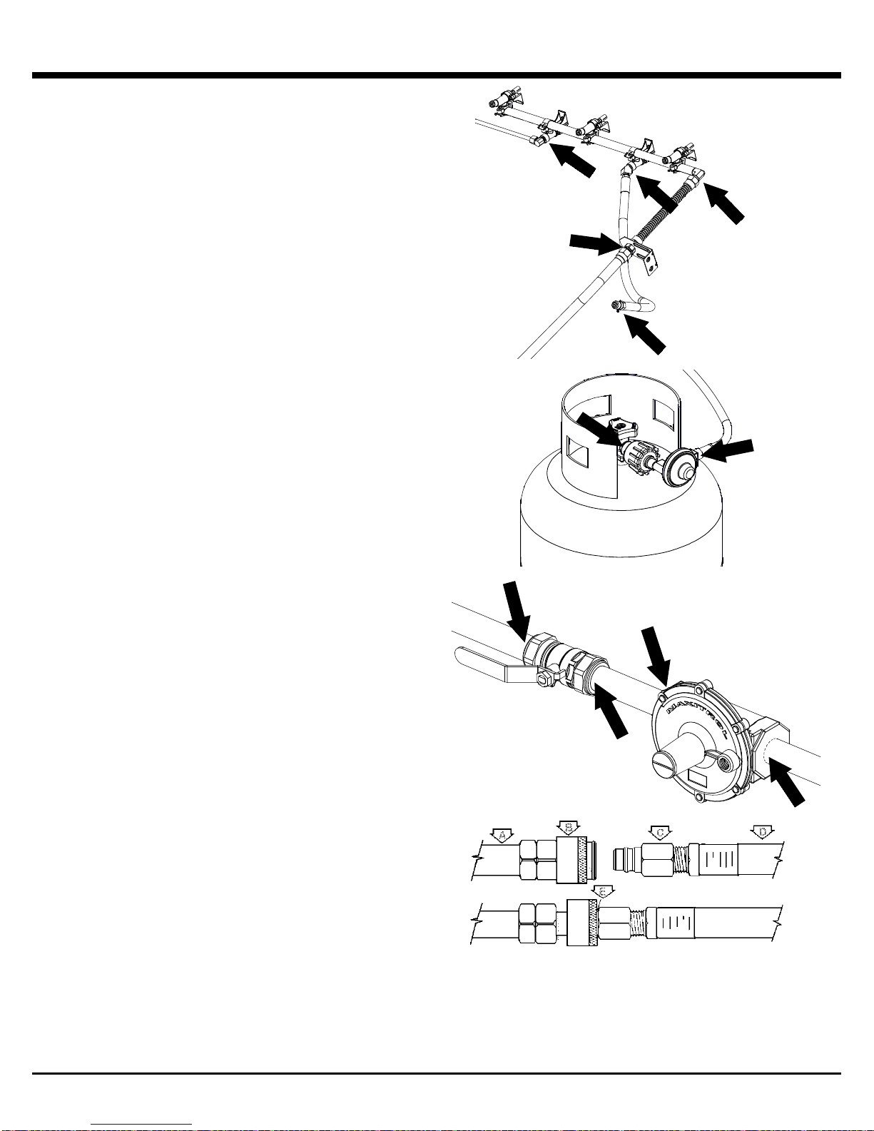
LEAK TESTING
All factory-made connections have been carefully tested for
gas leaks. However, shipping and handling may have
loosened a gas fitting.
AS A SAFETY PRECAUTION:
• Test all fittings for leaks before using your gas grill
• Test for leaks every time you disconnect and
reconnect a gas fitting, at least once per year or
after any period of nonuse
• Do not smoke while testing
• Never test for leaks with a lit match or open flame.
• Test for leaks outdoors
TO TEST FOR LEAKS:
1. Prepare a soap solution of one part water, one part
liquid detergent.
2. Extinguish any open flame or cigarettes in the area.
3. Make sure that gas grill valves are “OFF.”
4. Make sure that cylinder valve or the gas supply valve is
“OFF.”
5. With a full gas cylinder, open cylinder valve slowly. Or
open gas supply valve.
6. Brush the soap solution on each connection.
7. A leak is identified by a flow of bubbles from the area
of the leak.
8. If a leak is detected, close the gas cylinder valve or the
gas supply valve, tighten the connection and retest.
9. If the leak persists, contact your gas grill dealer for
assistance. Do not attempt to operate appliance if a leak
is present.
If your gas grill is equipped with a side burner or
rear burner:
1. Follow steps 1 - 5 above
2. Place fingertip over the opening in the orifice at the
end of hose.
3. Turn “SIDE”/”REAR” control to “HIGH.”
4. Brush soap solution on each connection between
orifice and control val ve.
5. Turn “SIDE”/”REAR” control to “OFF”.
A. GAS SUPPLY PIPING
B. QUICK DISCONNECT COUPLING
C. ADAPTER FITTING
D. EXTENSION HOSE ASSEMBLY
E. LEAK TEST HERE
13
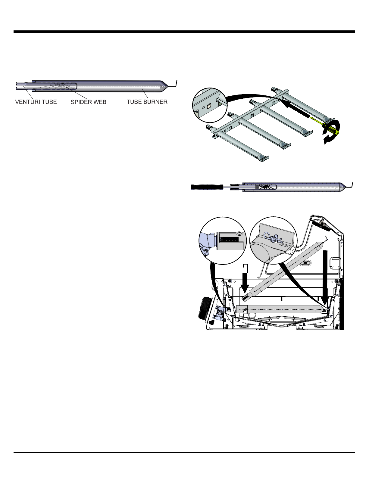
VENTURI TUBES
• Always keep venturi tubes clean
• Blockages in the venturi tubes caused by spiders,
insects and nests can cause a flashback fire
• Although the gas grill may still light, the backed up gas
can ignite and cause a fire around the venturi tubes at
the control panel or the side burner
If a flashback fire occurs, turn off gas at the source
immediately
Inspect and clean the venturi tubes (main burner, side
burner, rear burner) if any of the following symptoms
occur:
1. You smell gas.
2. Your gas grill does not reach temperature.
3. Your gas grill heats unevenly.
4. The burners make popping noises.
INSPECTING & CLEANING VENTURI
TUBES
1. Be sure that cylinder valve or the gas supply valve is “OFF”.
2. When gas grill is cool, remove the burner fasteners
and the top portion of the collector box. Proceed t o lif t
the burners from the gas grill housing.
3. Clean the venturi tubes with a pipe cleaner or
venturi cleaning tool (Accessory #77310 or #18270).
4. Lower the burner into position in the gas grill
housing, making sure that the venturi tubes are correctly
aligned and fitted on the orifices.
5. Secure burners with burner fasteners.
of collector box back in place
Snap top portion
14
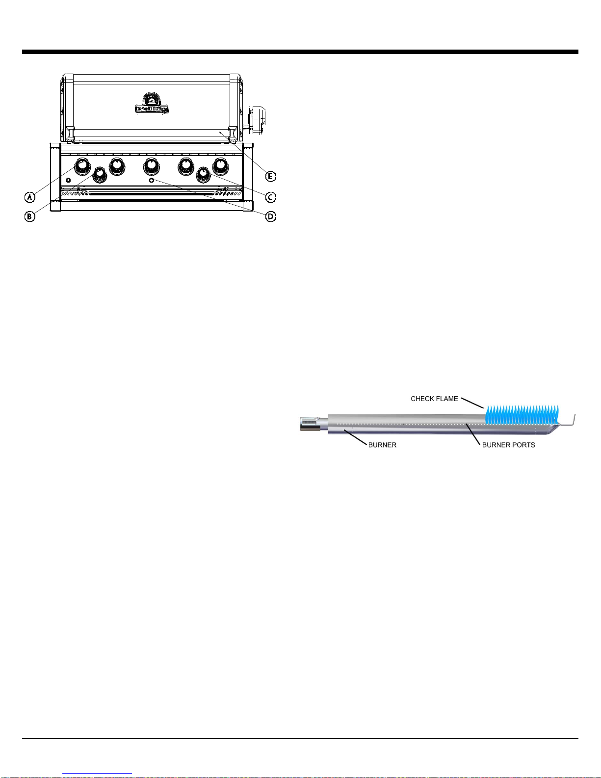
LIGHTING
BASIC GAS GRILL COMPONENTS
A. Main burner controls D. Ignitor
B. Side burner control E. Handle
C. Rear burner contr ol
LIGHTING INSTRUCTIONS
• The grill must be assembled and installed as per the
assembly and installati on instructions
• Ensure the grill is properly connected to the LP or
Natural Gas supply. See: “Hose and Regulator.” (Page
11)
• Ensure there are no gas leaks in the gas supply
system. See: “Leak Testing.” (Pages 13)
• Ensure that the venturi tubes are properly located over
the gas valve orifices. See Venturi diagram, (Page 14)
• Ensure that Main Burner, Side Burner and Rear Burner
ignition wires are connected
• Check that the battery has been installed in the
electronic ignition
• Carefully review all instructions on the information
plate attached to the gas grill
1. Open lid before lighting
2. Do not lean over gas grill while lighting.
3. Set control knobs to “OFF” and turn on the gas supply.
LIGHTING THE MAIN BURNER:
To light burner with the ignitor:
4. Push and turn one main burner control knob to “HIGH.”
5. Push and hold down the ignitor.
6. Burner should ignite within 5 seconds; turn off gas
source immediately if ignition does not occur in this
timeframe.
T
o light burner with a match:
4. Use the match holder and, apply lit match to burner
port.
5. Push and turn right main burner control knob to “HIGH.”
6. Burner should ignite within 5 seconds; turn off gas
source immediately if ignition does not occur in this
timeframe.
7. After the first burner is lit, push and turn the adjacent
main burner control knob to “HIGH” then repeat for
other burners; these burners should light automatically
without the ignitor.
Note: In windy conditions, ignite each burner individually.
LIGHTING THE SIDE BURNER:
To light burner with the Ignitor:
4. Push and turn side burner control knob to “HIGH.”
5. Push and hold the ignitor button.
6. Burner should ignite within 5 seconds.
To light burner with a match:
4. Apply lit match to burner ports.
5. Push in the side burner control knob and turn to “HIGH.”
6. Burner should ignite within 5 seconds.
Note: Pots on the side burner must not exceed 9” (23 cm)
in diameter or 15 lbs. (7 kg) in weight.
LIGHTING THE REAR ROTISSERIE
BURNER:
Warning: do not operate the main burner simultaneously
with the rear burner.
• REMOVE THE WARMING RACK
To light burner with the Ignitor:
4. Push and turn rear burner control knob to “HIGH.”
5. Push and hold the ignitor button.
6. Burner should ignite within 5 seconds.
To light burner with a match:
4. Apply lit match to burner ports.
5. Push in the rear burner control knob and turn to “HIGH.”
6. Burner should ignite within 5 seconds.
CAUTION: Check your gas grill after lighting. All burner
ports should show a 2.5cm / 1” flame on “HIGH.”
If any of the following symptoms occur there is
probably a blockage in the venturi tubes. Shut off gas
at once and clean the venturi tubes. See “Venturi
Tubes” (Page 14).
• You smell gas
• A flashback fire occurs
• Your gas grill heats unevenly
• The burners make popping noises
IF BURNER DOES NOT IGNITE:
• Push and turn control knob to “OFF.” Wait 5 minutes
then try again with control knob set at “MEDIUM”
• If any burner will not light, see “Troubleshooting” on
page 21. If problem persists, do not attempt to
operate the appliance; contact OMC, your dealer or an
approved service center
SHUTDOWN:
1. Turn LP gas cylinder valve or gas supply valve off.
2. Turn control knobs to “OFF.”
15

OPERATION
WARNING
NEVER cover slots, holes, or passages in the front or bottom
of the grill or cover an entire rack with material such as
aluminum foil. Doing so blocks air flow through the grill and
may cause over heating or carbon monoxide poisoning.
First Time Use
Before cooking on your gas grill for the first time, clean the
components and preheat the appliance to rid it of any odors
or foreign matter in the following manner:
• Remove and clean the cooking grids and Flav-R-Wave™
with mild soap and water
• With cooking grids and Flav-R-Wave™ removed, light
the gas grill following lighting instructions (see Page 15)
and operate the gas grill on “Medium” for 30 minutes.
Next, turn gas source off then turn all control knobs to the
“OFF” position
• Let grill cool, then replace the Flav-R-Wave™
• Season the cooking grids by coating grids with an organic
cold processed cooking oil wit h a hi gh s m oke point , light
the grill and operate on Med/Low for 30 minutes
• Recommended cooking oils:
o Avocado Oil – smoke point (260C/500F)
o Rice Bran Oil – smoke point (255C/490F)
o Canola Oil – smoke point (204C/400F)
• You are ready to grill. Proceed to “Preheating”
Preheating
• Preheat the gas grill on MEDIUM with the lid closed for
15 minutes
• Clean cold grids with a nylon grill brush (Item # 65643) or
hot grids with a stainless steel wire grill brush (Item #’s
65225, 64014, 64034) and carefully inspect to ensure
there are no broken bristles left on the grid
• Coat the grids with a high smoke point cooking oil
• Adjust heat as appropriate for what you are grilling
Lid Position
The position of the lid during cooking is a matter of personal
preference, but the gas grill cooks faster, uses less fuel, and
controls the temperature best with the lid closed.
A closed lid also imparts a smokier flavor to meat cooked
directly on the grid, and is essential for smoking and
convection cooking.
Vaporization Systems
Your gas grill is designed for use with the included Flav-RWave™ vaporization system. Do not use lava rock, ceramic
briquettes or any other vaporization system other than the one
that came with the gas grill.
COOKING TEMPERATURES
BROIL KING gas grills ar e:
• High-performance appliances capable of high searing
temperatures
• Designed with controlled airflow to retain heat and
minimize fuel consumption
Rarely, if ever, will you require the HIGH setting for
extended cooking or preheating.
High Setting
Produces temperatures at the cooking grid of approximately
700 - 750°F (370 - 400° C) with the lid down.
Use high setting only:
• For fast warm-up
• In cold or windy conditions when gri ll ing with th e lid up
• To quickly sear steaks before reducing the temperature
• To burn-off of food residue from the cooking grids and
Flav-R-Wave™ before cleaning (maximum 10 minutes)
Medium/High
Produces temperatures at the cooking grid of approximately
600°F (320° C) with the lid down.
Use medium/high setting to:
• Preheat grill for steaks
• Grill steaks rare & medium rare
Medium
Produces temperatures at the cooking grid of approximately
450° F (230°C) with the lid down.
Use medium setting to:
• Grill steaks medium and medium well
• Grill chops, burgers and vegetables
Medium/Low
Produces temperatures at the cooking grid of approximately
400° F (200°C) with the lid down.
Use medium/low setting to:
• Grill chicken pieces, s aus age, fish
• Roast, bake
• Grill dough and pastry such as quesadillas
Low
Produces temperatures at the cooking grid of approximately
310- 350° F (155-175° C) with the lid down.
Use low setting to:
• Slow roast and smoke large cuts of meat, delicate fish
and for dough and pastry
Temperatures are approximate only and vary with
outside temperature and the amount of wind.
the
16
COOKING TECHNIQUES
DIRECT GRILLING GUIDE
HEAT
SETTING
TIME PER
SIDE
TOTAL
MINUTES
CHICKEN
MED / WELL
MED / LOW
4 / 4 / 4 / 4
16
CHICKEN WINGS
MED / WELL
MED / LOW
5 / 5 / 5 / 5
20
HAMBURGER
MEDIUM
MED / LOW
3 / 3 / 3 / 3
12
HAMBURGERS
3/4” FROZEN
FISH FILLET
MEDIUM
MEDIUM
2 / 2 / 2 / 2
8 – 10
LOBSTER TAILS
SPLIT
USE SAME TECHNIQUE AS THE PERFECT STEAK GRILLING GUIDE
DIRECT GRILLING
The direct grilling method involves cooking the food on grids
directly over a lit burner. Direct grilling is the most popular
method for most single serving items such as steaks, chops,
fish, burgers, kebabs and vegetables.
1. Prepare food in advance to avoid delay and timing
problems. If using marinade or spices, they should be
applied before placing meat on the cooking grid. If basting
with sauces, they should be applied in the last 2-4 minutes
of grilling to avoid burning.
2. Organize the area around the gas grill to include forks,
tongs, oven mitts, sauces and seasonings to allow you to
stay in the vicinity of the gas grill while cooking.
3. Bring meat to room temperature just prior to grilling. Trim
excess fat from meat to minimize the “flare-ups” that are
caused by dripping grease.
4. Pre-heat the gas grill to the desired temperature with the
lid closed.
5. Coat the grids with vegetable or olive oil to prevent food
from sticking to the grids.
6. Hold the salt when cooking meats on the gas grill. The
meat will stay juicier if the salt is added after cooking.
7. To prevent steaks from “drying out,” use tongs rather than
a fork and start on “MEDIUM/HIGH” to sear the meat and
seal juices in. Reduce the heat and extend cooking times
when grilling thicker cuts of meat.
8. Learn to test when the meat is done by time and feel. Meat
firms up as it cooks. When the meat is soft it is rare. When
it is firm, it is well done.
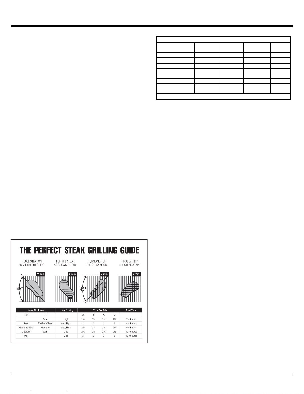
9. Follow the perfect steak grilling guide for most meat, fish,
poultry and vegetables.
1” THICK
MEDIUM MED / LOW 3 / 3 / 3 / 3 12
MEDIUM MEDIUM 4 / 4 / 4 / 4 16 - 20
17
COOKING TECHNIQUES
INDIRECT CONVECTION AND
ROTISSERIE COOKING GUIDE
BEEF ROAST
3 - 6 Lb.
MED / LOW
2 – 4 HRS
BEEF ROAST
6 - 10 Lb.
MED / LOW
3 – 5 HRS
PORK ROAST
2 - 5 Lb.
MED / LOW
2 – 4 HRS
PORK ROAST
6 - 10 Lb.
MED / LOW
3 – 5 HRS
TURKEY OR CHICKEN
2 - 5 Lb.
MED / LOW
2 – 4 HRS
TURKEY OR CHICKEN
5 - 10 Lb.
MED / LOW
3 – 5 HRS
WHEN USING ROTISSERIE BURNER, SET HE AT AT MED / HIGH
MEAT TEMPERATURE GUIDE
RARE
MED
WELL
BEEF / LAMB / VEAL
130°F / 55°C
146°F / 63°C
160°F / 70°C
PORK 150°F / 65°C
170°F / 77°C
POULTRY
170°F / 77°C
HAMBURGER
160°F / 70°C
FOR BEST RESULTS, USE A MEAT THERMOMETER
INDIRECT CONVECTION COOKING
This method is ideal for cooking large cuts of meat such as
roasts or poultry. The food is cooked by hot air circulating
around it.
• For most applications of convection cooking with and
without a rotisserie, a drip pan is recommended to catch
the drippings. Place drip pan on top of the Flav-R-Wave,
beneath center of food. Put half to one inch of water in
the drip pan. Fruit juice, wine or marinade may also be
added to enhance the flavor. Do not let the drip pan run
dry
• Convection cooking without a rotisserie is best with the
lid closed and the heat reduced. All burners can be set
to low or the outside burners can be set to medium and
the middle burner(s) can be turned off. Turning the
center burner off will prevent juices in the drip pan from
burning
• Prior to placing the meat on the gas grill, baste the meat
with vegetable oil. This will enhance browning on the
outside of the meat
• When cooking without a drip pan, close attention must
be paid to avoid the risk of a grease fire and is not
recommended
• Turn gas grill off and allow it to cool before removing drip
pan. The fat drippings are highly flammable and must be
handled carefully to avoid injury
• For convection cooking roasts and poultry without a
rotisserie, put meat in a roasting rack directly on grids
ROTISSERIE COOKING
Follow the steps for Indirect Convection Cooking. (See left)
• The rotisserie can accommodate up to 7 kg (15lb) of
meat with the limiting factor of rotating clearance. For
best results the meat should be centered on the center
line of spit to eliminate an out-of-balance condition
• The rotisserie can be used with the cooking grids in place
if space allows
• Fasten the meat securely on the spit prior to placing it on
the gas grill. For poultry, tie the wings and legs in tightly
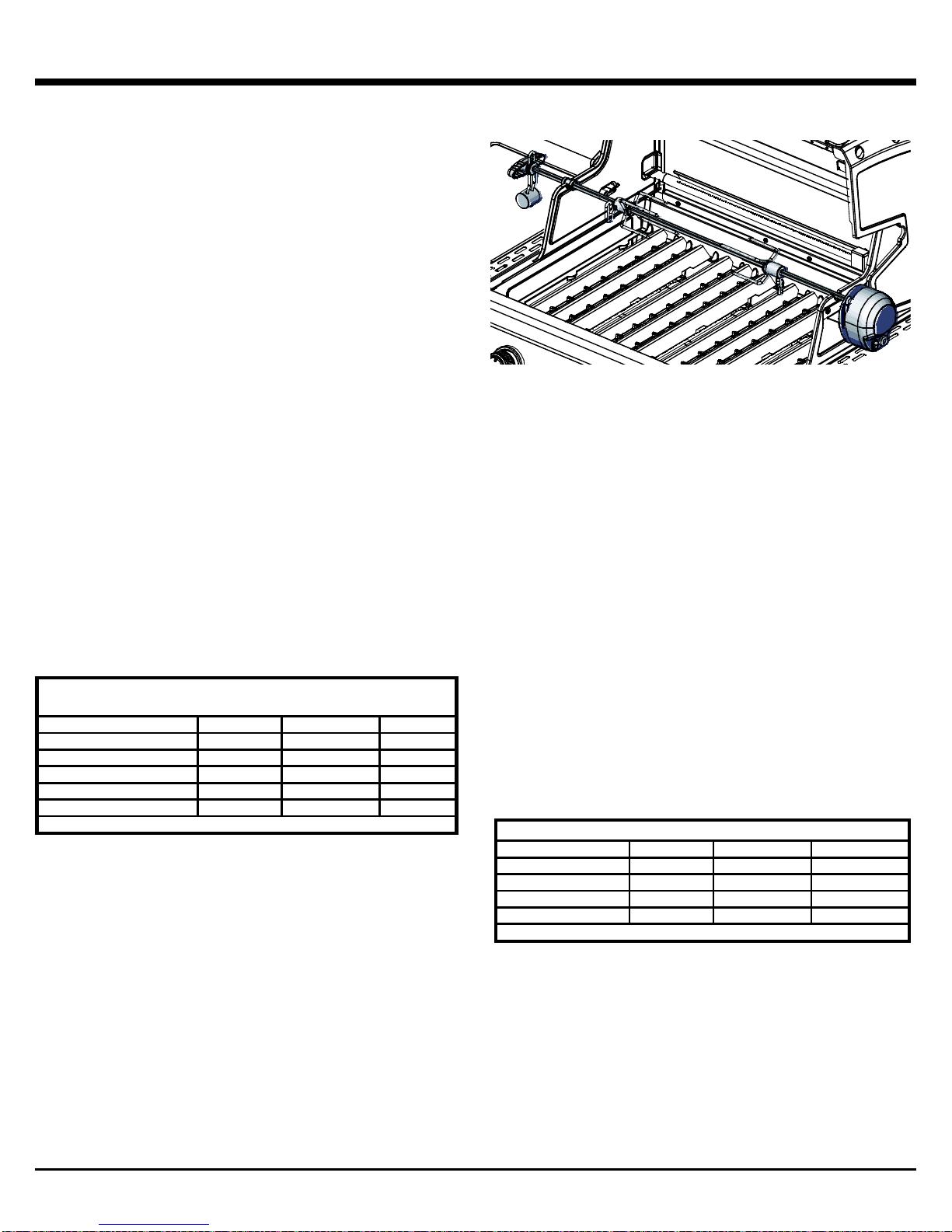
REAR BURNER ROTISSERIE
• Certain models feature a rear burner for rotisserie
cooking. The rear burner rotisserie method is the ultimate
for cooking roasts and poultry. With the heat source
located behind the food, there is no chance of a flare up
caused by fat drippings. A dish or drip pan placed below
the spit will collect the juices for basting or for preparing a
sauce
• The spring loaded rear burner may be easily removed
when not in use
• To operate your rear burner, see “Lighting the Rear
Burner.” (Page 15)
18
COOKING TECHNIQUES
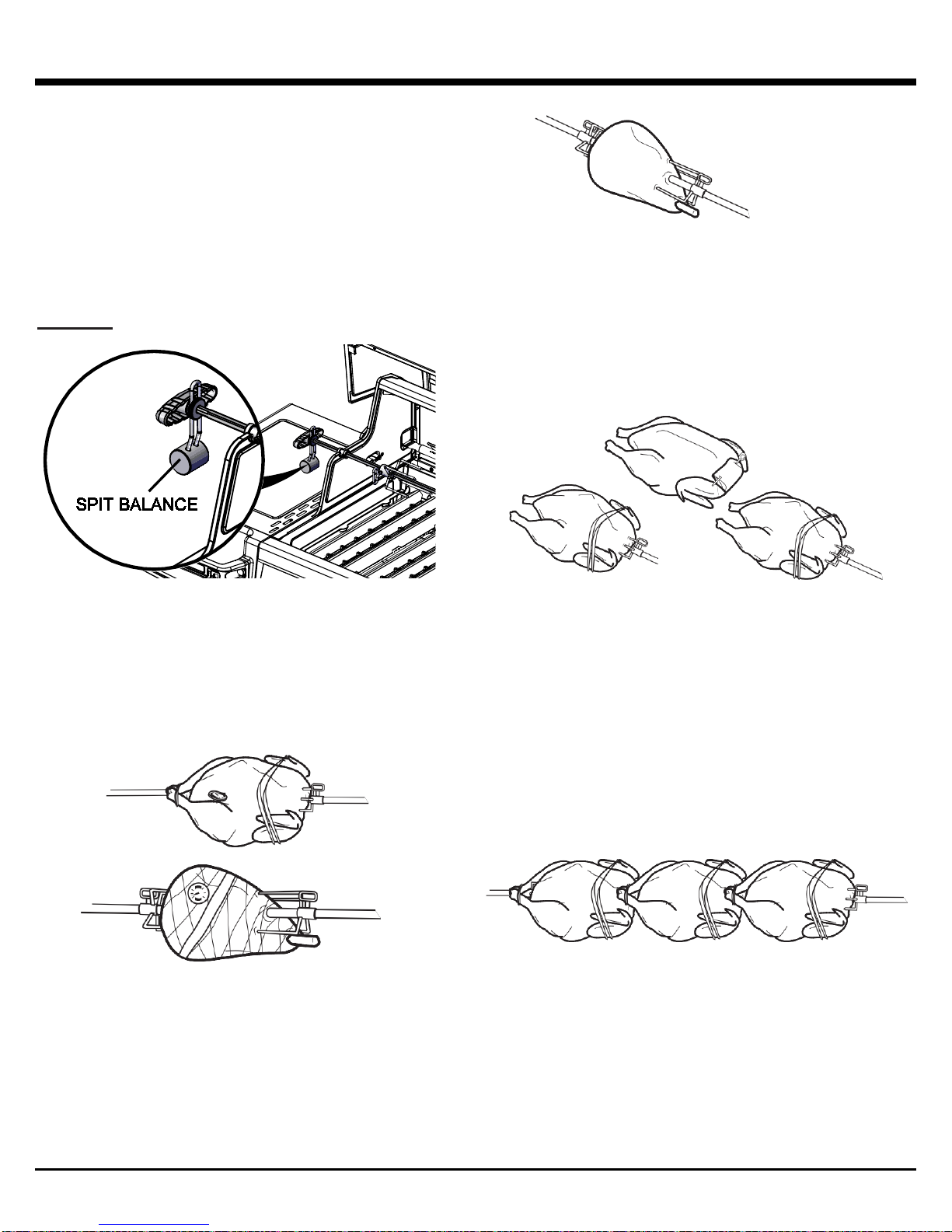
SPIT BALANCE
1. Loosen the rod handle to allow the balance to turn
freely.
2. Set the rotisserie rod in the slots of the gas grill casting.
Let the heaviest side of the meat rotate to the bott om.
3. Adjust the balance to the top of the rod, opposite the
heaviest side of the meat.
4. Tighten the rod handle. Periodically, check to see if the
meat turns smoothly while cooking. Adjust the spit
balance as necessary.
CAUTION: Use oven mitt when adjusting spit balance.
HOW TO USE A PROBE THERMOMETER
1. The accurate way to determine when a large piece of
meat is done is to use a probe thermometer. Insert the
thermometer at an angle so the sturdy pointed metal tip
rests in the center of the thickest part of the meat. Be
careful that it doesn’t touch the spit or the bone, and
that the point is not resting in fat (you will notice
much less resistance when probing in fat).
2. When the thermometer displays the desired temperature
the meat is done. Add your sauces during the last few
minutes of cooking time and let the meat stand about 15
minutes to firm up. Carve and serve.
• poultry: insert the tip of the thermometer in the thickest
part of the thigh close to the body
• ham or roasts: insert the tip of the thermometer in the
center of the heaviest section of the meat
USING A SPIT – LEG OF LAMB
1. Have 3” of bone sawed from small end of leg.
2. Leave meat around bone intact to form a flap.
3. Put a spit fork on rod.
4. Fold flap up and run rod through flap and leg.
5. Put second fork on rod and insert forks in each end of
leg. Test for balance. Tighten screws.
USING A SPIT – POULTRY
1. With breast down, bring neck skin up over cavity.
2. Turn under edges of skin; skewer to back skin.
3. Loop twine around skewer and tie.
4. Turn breast side up; tie or skewer wings to body.
5. Put a spit fork on rod. Insert rod in neck skin parallel to
backbone and exit just above tail.
6. Put second fork on rod and insert forks in breast and tail.
Test for balance. Tighten screws.
7. Tie tail to rod with twine. Cross legs; tie to tail.
THREE CHICKENS ON A SPIT
1. Tie or skewer wings to body.
2. Put a spit fork on rod. Place chickens on rod as
demonstrated in the above diagram.
3. Loop twine around tails and legs; tie to rod.
4. Put second fork on rod and insert forks in chicken.
Tighten screws.
19
MAINTENANCE
REGULAR MAINTENANCE
To ensure optimal performance and safety, the following
components should be inspected and cleaned as required before
use of your gas grill.
COOKING GRIDS - CAST IRON, CAST STAINLESS & HEAVY
ROD STAINLESS
BROIL KING® Deep V cast iron and cast stainless cooking grids
provide unsurpassed heat retention and grilling performance.
BROIL KING® Heavy Rod stainless grids provide maximum
durability and good heat retention and good grilling performance.
BROIL KING® cast iron grids are coated with a porcelain enamel
finish to protect the grids and reduce the tendency of food sticking
to grids. Regular use a nd care improves performance and longevity
of the grids.
For optimum performance:
• Before first use and after long periods of storage, wash grids
using a light detergent and water and then rinse and dry with
paper towel; never air dry grids or use a dishwasher
• Immediately after washing, season cooking grids by coating
grids with an organic cold pressed cooking oil with a high
smoke point, light the grill and operate on Med/Low for 30
minutes. Recommended cooki ng oils:
o Avocado Oil – smoke point (260C/500F)
o Rice Bran Oil – smoke point (255C/490F)
o Canola Oil – smoke point (204C/400F)
• Before and after each use, brush grids with a good quality
stainless steel br istle brush (Item #’s 65225, 64014, 64034)
and lightly coat with a high smoke point cooking oil. This will
continue the seasoning process
• Use medium heat settings to preheat and grill to avoid
burning off the protective seasoned coating
• Avoid applying sugar based marinades or salt to meat before
grilling, apply sugar based marinades at end of grilling and salt
after grilling
• Use oil based marinades, avoid water based marinades
• Lightly coat food with cooking oil of your choice before grilling
• Turn and rotate your grids periodically
• Ensure the surface of the grid is always coated with a light
layer of oil. This helps prevent rust and deterioration and
improves the grids non-stick performance
• If rust does occur, Burn-Off the grid, brush with a stainless
steel br istle brush and re-season
During long periods of inactivit y , grids should be seasoned, then
stored in a dry place. The grids may be wrapped in protective
plastic food wrap. After periods of storage, Burn-Off grids, wash,
dry with paper towel and re-season with high smoke point cooking
oil.
Warning:
If the grill is hot, use caution and oven mitts while handling
the stainless steel bristle brush.
Inspect the grids carefully after brushing to ensure there are
no broken bristles left on the grid.
GREASE TRAY
The grease tray is in the pull out drawer located under the control
panel. Clean regularly.
FLAV-R-WAVE™
The Flav-R-Wave™ is designed to generate smoke and vapor from
the food drippings in order to provide that authentic barbecue flavor
while protecting the burner. If residue accumulates on the Flav-RWave™, remove the cooking grids and scrape the residue off the
Flav-R-Wave™ with the grid lifter. (Part # 60745)
GENERAL CLEANING
Perform a Burn-Off (see below).
When gas grill is cool, remove grids, scrape the Flav-R-Wave™
clean with grid lifter then remove the Flav-R-Wave™.
Clean the interior of the gas grill as necessary by scraping the sides
and bottom of the cook box with the grid lifter and vacuum residue.
Rust is a natural oxidation process and may appear on internal
stainless steel parts. Rust will not affect performance of your grill.
BURN-OFF
Ignite the burners as per “Lighting” (page 15).
Operate gas grill on HIGH with lid closed for 10 minutes maximum.
Turn the gas source off then turn control knobs to OFF.
ANNUAL MAINTENANCE
The following components should be inspected and cleaned at
least once a year or after any period of storage over 30 days to
ensure optimal performance, safety and efficiency.
BURNER
Remove burner and inspect for cracks and deterioration. Clean
venturi tubes using a pipe cleaner or venturi brush to eliminate any
blockages. See “Venturi Tubes.” (Page 14) While the burner is
removed, remove the grease shiel ds, clean the interior of cook box
by scraping the sides and bottom of the cook box and vacuuming.
HOSE
Inspect and replace if necessary. For propane see “Hose and
Regulator.” (Page 11)
EXTERIOR ALUMINUM COMPONENTS
If white oxidation spots appear, wash the outside of the aluminum
cook box with a mild soap and water solution. Rinse the surfaces
thoroughly then wipe them with a cloth dipped in cooking oil to
restore the luster. For repair of paint scratches and scuffs, use a
good quality HIGH temperature (600°F) spray paint for touch-up.
STAINLESS STEEL & PORCELAIN COMPONENTS
Wash with soap and water. Use stainless steel cleaner or “Bar
Keepers Friend” to polish and remov e stai ns or rust marks if they
occur. Weathering and extreme heat can cause a stainless steel lid
to turn a tan color. This is discoloration and is not considered a
manufacturing defect.
RESIN COMPONENTS AND SIDE SHELVES
Wash with soap and water.
REPLACEMENT PARTS
If a problem is found with the regulator, hose, burner, or control
valves, do not attempt repair. See your dealer, approved service
center, or contact the factory for repairs or replacement parts. To
ensure optimum performance, use only origin al BROIL KING®
replacement parts.
LEAK TEST
When reconnecting a gas cylinder on propane models, be sure to
check for leaks. See “Leak Testing.” (Page 13)
20
TROUBLESHOOTING
PROBLEM
POSSIBLE CAUSE
CORRECTIVE ACTION
Leak detected at cylinder,
regulator or other connection.
1. Regulator fitting loose.
2. Gas leak in hose/regulator or control valves.
1. Tighten fitting and “Leak Test.” (page 13)
2. See authorized service center.
Flames Beneath Control Panel
(Flashback Fire)
1. Venturi blocked.
1. Remove burner and clean venturi. See “Venturi Tubes”
(page 14)
Flickering Burner Flame or
1. Excess flow safety device has been activated in
1. Turn LP cylinder valve off then turn all burners to OFF
Burner Not Lighting
1. Out of LP gas, gas supply not connected.
1. Refill LP gas cylinder, check connections to supply.
cessfully, it is an ignitor issue.
Ignitor Not Working
1. Ignitor battery is dead
4. Ignitor malfunction
1. Replace battery
4. Use “Match Lighting” procedure. (Page 15)
Decreasing Heat, “Popping
1. Out of LP Gas.
1. Refill LP Gas Cylinder.
Hot spots on Cooking Surface
1. Venturi blocked
1. Remove burner, clean venturi. See “Venturi Tubes”
“Flare-ups” or Grease Fires
1. Excessive grease buildup on vaporizer or in gas grill
1. Thoroughly scrape off Flav-R-Wave and inside of cookbox
Regulator Humming Noise
1. Cylinder valve opened too quickly.
1. Open cylinder valve slowly.
Yellow Flame
1. Some yellow flame is normal. If it is excessive, the
1. Remove burner, clean venturi. See “Venturi Tubes” (page
Inside of Lid Appears to be
1. This is a build-up of grease. The inside of lid is not
1. Clean with stiff bristle brush or scraper.
Cooking Grids Rusting
1. Porcelain enamel has been chipped
1. See “Maintenance” (page 20) for help
Control panel or oven lights not
1. Unit not connected to power.
4. Bulb blown
1. Connect GFI power cord to appliance. Plug to working
4. Replace bulbs.
If troubleshooting fails to solve any of these or any other issues, please visit www.omcbbq.com for more information including troubleshooting
videos, and tips or call customer service at 1-800-265-2150
SMELL OF GAS
Low Temperatures on HIGH
Setting
SHUT OFF GAS SUPPLY AT ONCE.
DO NOT USE THE APPLIANCE UNTIL LEAK IS SEALED.
connection between cylinder and barbecue.
2. Ignitor issue.
3. Excess flow safety device has been activated.
4. Regulator is not fully connected to the cylinder valve.
5. A leak in the system causing the excess flow device
to activate.
6. Venturi blocked or misaligned with valve orifice.
7. Orifice(s) blocked.
8. Hose is twisted.
position. Disconnect the regulator from the cylinder. Wait
two minutes. Re-attach regulator to the cylinder. Open the
cylinder valve slowly. Wait one minute. Light grill as per
“Lighting” (page 15)
2. Try manually lighting burner with a match. See “Lighting”
(page 15). If burner lights suc
See “Ignitor not Working” below
3. Follow “Flickering Flame or Low Temperatures on HIGH
setting” solution above.
4. Tighten the regulator hand wheel.
5. Leak test connections to determine loose fitting. Tighten
fitting. Leak test system.
6. Remove burner, clean venturi and realign with valve
orifice. See page 14 for assistance.
7. Remove burner, clean orifices with a pin or fine wire. Do
not drill orifices.
8. Straighten hose. Keep away from bottom casting.
Sound”
Peeling
working
2. Ignitor wire(s) not connected
3. Electrode misaligned on burner
2. Venturi blocked.
2. Debris buildup on Flav-R-Wave
cook box
2. Excessive heat.
venturi may be blocked.
2. Burner ports blocked.
painted and cannot peel.
2. Faulty transformer.
3. Loose or corroded connections.
2. Ensure main burner and side burner electrode wires are all
connected
3. Realign electrode and clear any surrounding debris from
area
2. Remove burner, clean venturi. See “Venturi Tubes”
(Page 14) for assistance.
(page 14) for assistance.
2. Scrape off Flav-R-Wave and vacuum
then vacuum out debris
2. Turn burner controls to a lower setting
14) for assistance.
2. Remove burner & clean with soft bristle brush (e.g.
toothbrush).
power outlet.
2. Check transformer output is 12Vac. Replace if required.
3. Clean connections and ensure all connectors are pushed
together firmly.
21
 Loading...