

Page 1
PREMIUM GRILLS
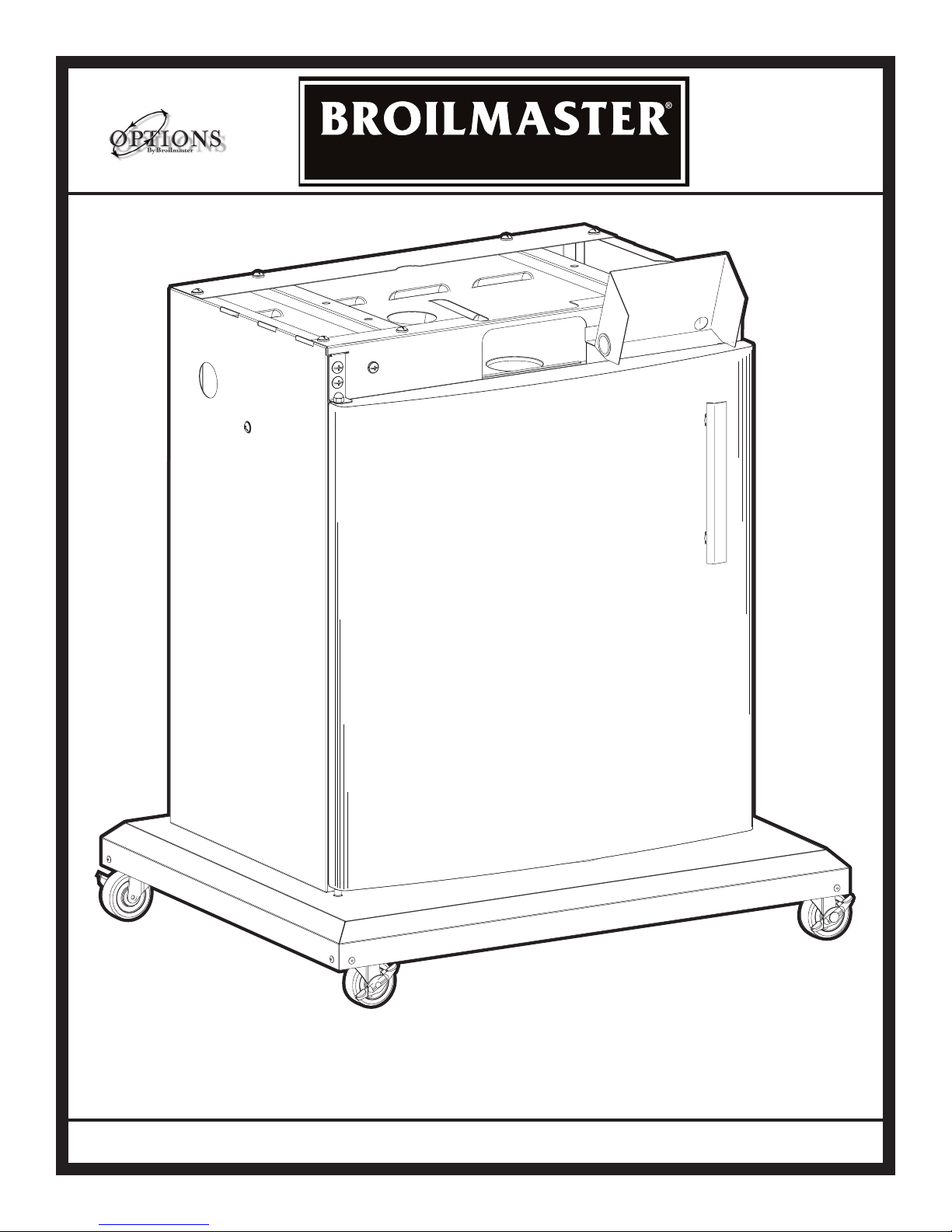
Cart With Door
retain oWner’s Manual for future referenCe.
PSCB1-3
Page 1
Page 2
IMPORTANT INFORMATION
IMPORTANT
This manual should be read thoroughly by the installer and by anyone who will use
or maintain the grill.
Installer - Write the model number, serial number, and date of installation in the manual.
If available, attach a copy of the receipt. Leave this manual with the grill owner.
Grill Owner - Read and retain this manual. It contains instructions on using and maintaining your grill, plus information on ordering replacements parts. Attach a copy of
your receipt to this manual. Your receipt established the proof of purchase required
for warranty replacement parts.
WARNING
Follow the instruction in this manual for proper installation and maintenance of the
grill. Improper installation, adjustment, alteration, service or maintenance can cause
injury or property damage. For assistance or additional information consult a
qualied installer, service agency or the gas supplier.
WARNING: FOR YOUR SAFETY
Do not store or use gasoline or other ammable vapors or liquids in the vicinity of
this or any appliance.
CAUTION:
Parts may have sharp edges. Wear leather work gloves and handle parts carefully
during unpacking, assembly and installation.
B102237-0-0714Page 2
Page 3

Thank you for purchasing a Broilmaster Grill Accessory.
Broilmaster takes pride in its reputation as the The Most Durable Grill Known to Man.
From its thick aluminum casting to its massive cooking grids, your Broilmaster
is built to last. In fact we still make replacement parts for Broilmaster grills built
more than 30 years ago.
Visit www.broilmaster.com and click on the Hall of Fame to see a sampling of
our long-time customers. We hope you enjoy years of great meals prepared on
your Broilmaster. And we hope to add your photo to the Hall of Fame one day.
Thank You!
B102237-0-0714 Page 3
Broilmaster is a registered trademark of
Empire Comfort Systems, Inc.
918 Freeburg Ave.
Belleville, Illinois 62220
Telephone 800-851-3153
Page 4

TABLE OF CONTENTS
Y
ou have chosen the nest grill for your outdoor cooking pleasure.
Please take time to read this entire manual before assembling your Broilmaster Grill Accessory.
ASSEMBLY INSTRUCTIONS ..................................................................................................... 5
IMPORTANT INFORMATION .....................................................................................................6
PSCB1 CART ASSEMBLY .................................................................................................... 7-21
CART PARTS DIAGRAM ...........................................................................................................
CART HARDWARE PACK - B102003 .......................................................................................
PATIO MOUNT CART ONLY .................................................................................................
CART WALLS ASSEMBLY ......................................................................................................
ATTACH WALLS TO BASE ......................................................................................................
INSTALL STABILIZING BRACKET ..........................................................................................
INSTALL IGNITOR SHIELD .....................................................................................................
INSTALL STIFFENER BRACKETS .........................................................................................
SECURE LEFT AND RIGHT PANELS TO REAR PANEL .......................................................
INSTALL DOOR ........................................................................................................................
ATTACH BOTTOM CASTING TO CART .................................................................................
HEAT SHIELD PLACEMENT ...................................................................................................
ATTACH HOSE & COUPLING .................................................................................................
TANK RETAINER AND GREASE DRIP TRAY INSTALLATION ..............................................
GRILL MAINTENANCE HISTORY ...........................................................................................22
MASTER PARTS DISTRIBUTOR LIST .................................................................................... 23
HOW TO ORDER REPAIR PARTS .......................................................................................... 23
9-10
11
12
13
14
15
16
17
18
19
20
21
7
8
B102237-0-0714Page 4
Page 5
ASSEMBLY INSTRUCTIONS
Before You Begin
Compare the parts in the box to the parts list provided in this manual. If any are missing, contact your
Broilmaster dealer before beginning assembly.
All Broilmaster grills require some assembly. For the best results, follow the step-by-step instructions.
For natural gas grills and for permanently mounted LP grills, have your gas supplier run service to the desired
location first.
If you purchased an accessory with your Broilmaster, follow the instructions provided.
CAUTION:
Parts may have sharp edges. For your safety
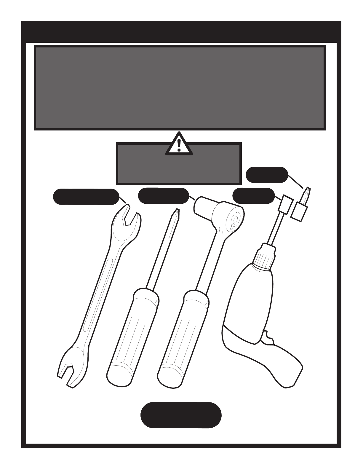
3/8”, 7/16”and 3/4”
REQUIRED
wear leather work gloves and handle parts
carefully during unpacking and assembly.
3/8”and 7/16”
3/8”and 7/16”
3/8”and 7/16”
REQUIRED
REQUIRED
REQUIRED
3/8”and 7/16”
3/8”and 7/16”
PHILLIPS
5/16”
REQUIRED
REQUIRED
DECK MOUNT
BIT
B102237-0-0714 Page 5
TOOLS
REQUIRED
Page 6

IMPORTANT INFORMATION
Grill Location
This grill is designed for outdoor use only.
Never operate your grill in any building, garage, or other
enclosed area. Never operate your grill in a recreational vehicle
or boat. Never operate your grill under any combustible materials,
such as carports, covered porches, awnings, or overhangs.
CAUTION
Keep the sides of the grill at least 16 inches from any
combustible material. Keep the back of the grill at least
18 inches from any combustible material. Placing a hot
grill too close to a building or other combustible mate-
rial may lead to re, property damage, or personal injury.
Combustible materials include fences, patio furniture,
and your home.
Keep the area around the grill clear to ensure proper ventilation.
WARNING
Do not install or operate this grill where gasoline or other
ammable materials are used or stored. Failure to comply
with this warning could result in explosion or re causing
property damage or personal injury.
your Broilmaster dealer.)
CAUTION
The grill and its individual shutoff valve must be discon-
nected from the gas supply piping system during any
system pressure testing at test pressures in excess of
1/2 PSIG.
CAUTION
The grill must be isolated from the gas supply piping sys-
tem by closing its individual manual shutoff valve during
any pressure testing of the gas supply piping system at
test pressures equal to or less than 1/2 PSIG.
Cleaning
The exterior of your cart may be cleaned with hot water and mild
detergent as needed.
Stainless steel surfaces may be cleaned with a spray-on stainless steel cleaner available at most hardware stores.
Important: Do not use harsh or abrasive cleaners! Your cart or
post has a highly polished surface and may be easily scratched.
Gas Type
The type gas required for your grill can be determined from the
product identication label located on the grill’s control panel.
Questions regarding different types of gases should be directed
to your local gas supplier.
CAUTION
Never use Liquid Propane (LP) gas in a grill designed
for Natural gas, or Natural gas in a grill designed for
Liquid Propane gas. Questions regarding different types
of gases should be directed to your local gas company.
Connection Requirements
Broilmaster natural gas grills are not equipped with pressure
regulators. Your gas grill operates at a manifold pressure of
seven inches water column. (Your natural gas technician will
understand what this means.)
Arrange with your local gas company or licensed contractor to
have a gas supply line connected to the inlet of the stainless
steel ex tube assemble. The gas supply must have a shutoff
valve that is close to the post in case of emergency and must
be shutoff when the grill is not in use.
Periodic Inspection and
Maintenance
Periodic inspections and maintenance are essential. All Broilmaster Grill products or mechanical devices eventually begin
to wear due to environment, contaminants, corrosion or aging.
Inspect all components at least twice per year and replace any
that show wear.
If any parts are damaged or missing, you may order parts from
your local Broilmaster® dealer. Please refer to the Parts Diagram and Parts List sections of this manual for more detailed
information.
Connect your grill this coupling using the twelve foot exible
hose with a quick disconnect tting (available for purchase from
B102237-0-0714Page 6
Page 7
PSCB1 CART ASSEMBLY
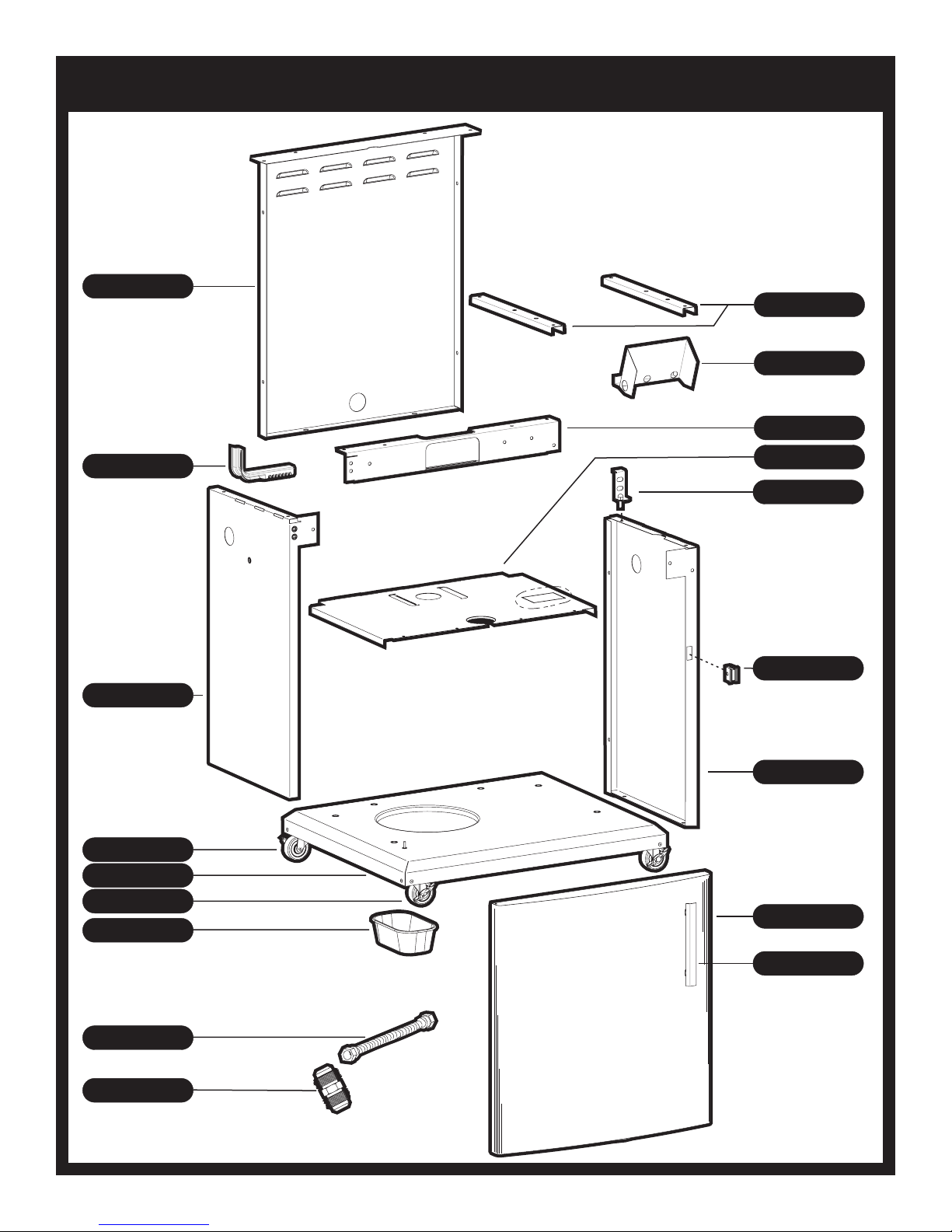
CART PARTS DIAGRAM
B101714 (1)
REAR PANEL
B101760 (1)
TANK RETAINER BRACKET
B101752 (2)
STIFFENER BRACKET
B101752 (1)
IGNITOR HEAT SHIELD
B101771 (2)
STABILIZING BRACKET
B101709 (1)
HEAT SHIELD
B101786 (1)
HINGE ASSEMBLY
BB101772(1)
LEFT PANEL
B063103 (2)
CASTER WITHOUT BRAKE
B101690 (1)
BASE ASSEMBLY
B063104 (2)
CASTER WITH BRAKE
B060337 (1)
GREASE DRIP TRAY
B101900 (1)
FLEX HOSE
B101831 (1)
COUPLING
B101761 (1)
MAGNET
B101691 (1)
RIGHT PANEL
B101691 (1)
DOOR WITH HANDLE
B101762 (1)
DOOR HANDLE
B102237-0-0714 Page 7
Page 8
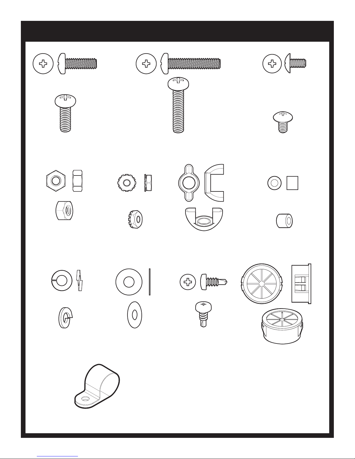
CART HARDWARE PACK - B102003
PHILLIPS PAN HEAD SCREW,
SS,1/4-20 X 3/4
B072217
(23)
HEX NUT,
SS,1/4-20
B076331
(15)
KEPS NUT,
SS,10-24
B073967
(1)
PHILLIPS PAN HEAD SCREW,
SS,1/4-20 X 1-1/4
B100113
(5)
WING NUT,
1/4-20
R1123
(1)
PHILLIPS TRUSS HEAD
SCREW
SS,10-24 X 3/8
B100130
(4)
DOOR SPACER
B101758
(1)
LOCK WASHER,
1/4 ID X 1/2 OD
B076333
(22)
CABLE CLIP
B101996
(1)
FLATWASHER,
SS,1/4 ID X 5/8
SELF-DRILLING PHILLIPS
OD
B076332
(4)
PAN HEAD SCREW,
SS,10-16 X 1/2
R4059
(2)
SNAP BUSHING,
STAR
R882
(1)
Standard hardware items such as bolts, screws, washers, and nuts can
be purchased at your local hardware store. Do not order individual pieces of standard hardware. A replacement hardware pack may be ordered
using the hardware pack part number at the top of the page.
B102237-0-0714Page 8
Page 9

Place the Base Assembly on the work
surface with casters facing up. Remove
the four screws securing each caster and
retain for possible future use. Repeat
steps for remaining three casters.
Patio Mounting Start here. If not hard
mounting cart to deck skip to page 11.
5/16”
PATIO MOUNT CART ONLY
SELF-DRILLING
HEX HEAD SCREW,
10-24 X 1/2
R2737 (16 ALREADY INSTALLED)
B102237-0-0714 Page 9
Page 10
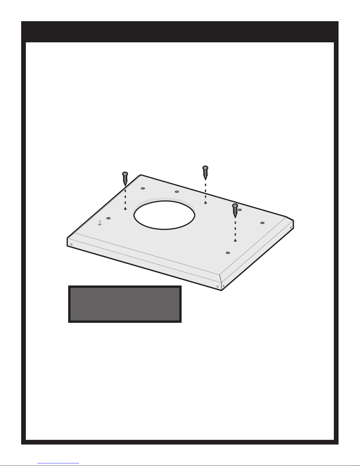
Use three deck screws of at least 2-1/2
inches (Not Included) in length to fasten
Base Assembly to deck. The screws
used should protrude at least 3/4 inch
into the deck.
PATIO MOUNT CART ONLY
B102237-0-0714Page 10
Page 11

Be careful when handling parts, as
they may contain sharp edges. Work
gloves are recommended to prevent
injury.
Remove protective plastic covering.
3/8”,7/16”
Do Not Tighten
until next step.
Clip installed in upper left corner is
used to route gas line.
CART WALLS ASSEMBLY
PHILLIPS PAN HEAD SCREW,
SS,1/4-20 X 3/4
B072217 (3)
HEX NUT,
SS, 1/4-20
B076331(3)
PHILLIPS TRUSS HEAD SCREW,
SS,10-24 X 3/8
B100130 (1)
KEPS NUT,
SS, 10-24
B073967(1)
LOCK WASHER,
1/4 ID X 1/2 OD
B076333 (3)
CABLE CLIP,
B101996 (1)
.
.
.
.
.
B102237-0-0714 Page 11
Page 12
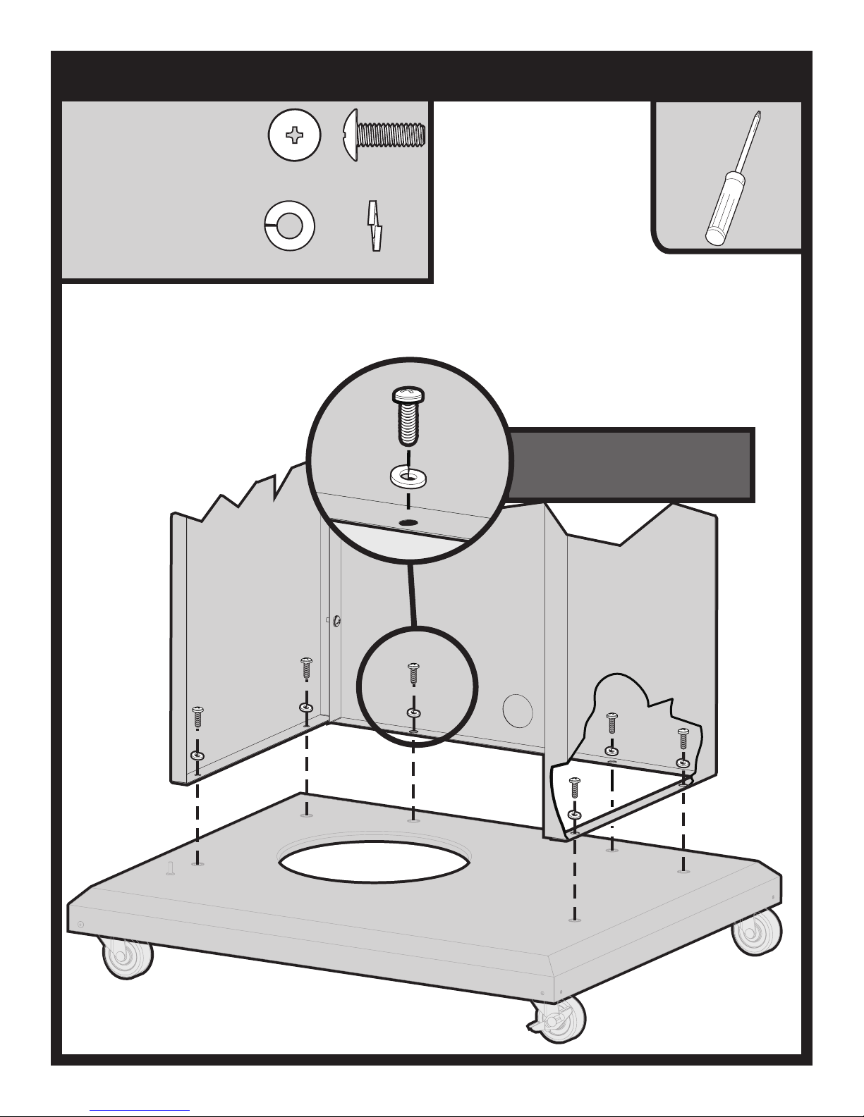
ATTACH WALLS TO BASE
PHILLIPS PAN HEAD SCREW,
SS,1/4-20 X 3/4
B072217 (6)
LOCK WASHER,
1/4 ID X 1/2 OD
B076333 (6)
.
Install all six Screws before tightening.
After tightening the Base Assembly
screws, tighten the nuts and screws
from previous step.
B102237-0-0714Page 12
Page 13

INSTALL STABILIZING BRACKET
PHILLIPS PAN HEAD SCREW,
SS,1/4-20 X 3/4
B072217 (6)
HEX NUT,
SS, 1/4-20
B076331(4)
LOCK WASHER,
1/4 ID X 1/2 OD
B076333 (4)
.
.
7/16”
B102237-0-0714 Page 13
Secure the Stabilizing Bracket to
Cart Assembly. Do Not Tighten.
Do Not Tighten
Page 14

INSTALL IGNITOR SHIELD
PHILLIPS PAN HEAD SCREW,
SS,1/4-20 X 3/4
B072217 (2)
HEX NUT,
SS, 1/4-20
B076331(2)
SNAP BUSHING,
STAR
R882(1)
LOCK WASHER,
1/4 ID X 1/2 OD
B076333(2)
.
.
7/16”
B102237-0-0714Page 14
Page 15

INSTALL STIFFENER BRACKETS
PHILLIPS PAN HEAD SCREW,
SS,1/4-20 X 3/4
B072217 (4)
HEX NUT,
SS, 1/4-20
B076331(4)
LOCK WASHER,
1/4 ID X 1/2 OD
B076333 (4)
.
.
7/16”
CART FRONT
B102237-0-0714 Page 15
Place Stiffener Brackets under the
ledges of the Stabilizing Bracket and
Rear Panel.
Page 16
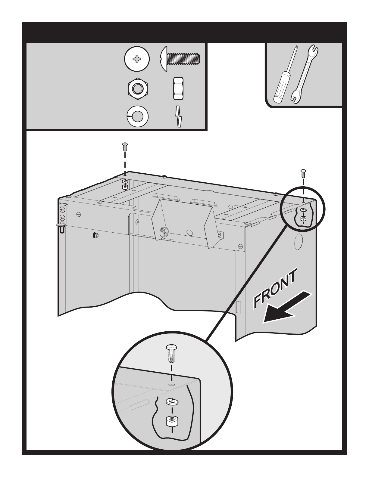
SECURE LEFT AND RIGHT PANELS TO REAR PANEL
PHILLIPS PAN HEAD SCREW,
SS,1/4-20 X 3/4
B072217 (2)
HEX NUT,
SS, 1/4-20
B076331(2)
LOCK WASHER,
1/4 ID X 1/2 OD
B076333(2)
.
.
7/16”
B102237-0-0714Page 16
Page 17
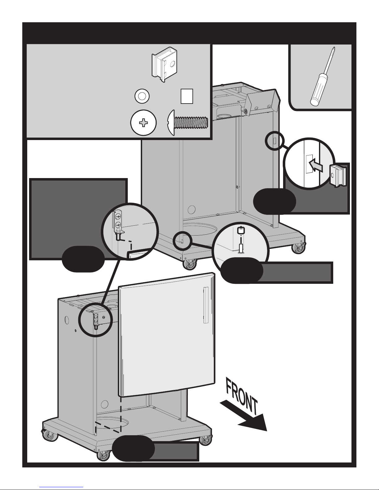
INSTALL DOOR
DOOR MAGNET,
B101761 (1)
DOOR SPACER
B101758 (1)
PHILLIPS PAN HEAD SCREW,
SS,1/4-20 X 3/4
B072217 (2)
(FROM PREVIOUS STEP)
Place Peg on Hinge Assembly
into the hole on the top left of
the Door. Slide the tab on the
Hinge Assembly into the slot
on the Stabilizing Bracket.
Before tightening
screws, align Door so
that it moves freely.
Tighten screws left
loose from
previous
4
Snap Magnet into
the hole provided
in the Right Panel
3
1
Place plastic Spacer
on Peg on Cart Base
2
B102237-0-0714 Page 17
Place Door on
Peg.
Page 18

ATTACH BOTTOM CASTING TO CART
PHILLIPS PAN
HEAD SCREW,
SS,1/4-20 X 1-1/4
B100113 (4)
FLAT WASHER,
SS,1/4 ID X 5/8 OD
B076332 (4)
.
B102237-0-0714Page 18
Page 19

HEAT SHIELD PLACEMENT
SELF-DRILLING PHILLIPS PAN HEAD SCREW,
SS, 10-16 X 1/2
R4059 (4)
Break out this rectangle if
the Cart is to be used with
a Q3X Series Grill.
HEAT
SHIELD
KNURL NUT
2
1
KNURL NUT
Slide Heat Shield over the knurl nut on
the Left Panel. Swing Heat Shield into
place. The Rear Tabs on the Heat Shield
will fit into the Upper Row of Louvers.
3
4
Secure Heat Shield to the Stabilizing
B102237-0-0714 Page 19
Bracket with
four self drilling screws.
Page 20

ATTACH HOSE & COUPLING
VALVE
Attach the included flex hose to the
fitting on the Burner Control Valve
mounted on the Control Panel.
Attach the included coupler and your
Regulator Hose (LP) or Supply Line
(LP or Natural) to the flex hose
Tighten this connection withawrench.
3/4”
The included Flex Hose and Coupler
must be used with PSCB carts.
FLEX HOSE
COUPLING
REGULATOR
HOSE (LP)
SUPPLY LINE
(LP OR NAT)
OR
Route hose through Cable Clip at
rear inside of Cart.
B102237-0-0714Page 20
Page 21

TANK RETAINER AND GREASE DRIP TRAY INSTALLATION
PHILLIPS PAN HEAD SCREW
SS,1/4-20 X 1-1/4
B100113 (1)
WING NUT,
1/4-20
R1123 (1)
.
LOCK WASHER,
1/4 ID X 1/2 OD
B076333(1)
.
Grease Drip Tray must be emptied
periodically.
B102237-0-0714 Page 21
Page 22

GRILL MAINTENANCE HISTORY
Date Maintenance Performed
B102237-0-0714Page 22
Page 23

MASTER PARTS DISTRIBUTOR LIST
To order parts under warranty, please contact your local Broilmaster dealer. See the dealer locator at www.broilmaster.com.
To provide warranty service, your dealer will need your name and address, purchase date and serial number, and the
nature of the problem. Please keep your receipt to establish ownership and date of purchase.
To order parts after the warranty period, please contact your dealer or one of the Master Parts Distributors listed below.
The Master Parts Distributor list changes from time to time. For the current list go to www.broilmaster.com and click on
the Parts button.
Note: Master Parts Distributors are independent businesses that stock the most commonly ordered repair parts.
Dey Distributing
1401 Willow Lake Boulevard
Vadnais Heights, MN 55101
Victor Division of F. W. Webb Company
200 Locust Street
Hartford, CT 06114
Phone: 651-490-9191
Toll Free: 800-397-1339
Website: www.deydistributing.com
Parts: Heater, Hearth and Grills
Phone: 860-722-2433
Toll Free: 800-243-9360
Fax: 860-293-0479
Toll Free Fax: 800-274-2004
Websites: www.fwwebb.com & www.victormfg.com
Parts: Heater, Hearth and Grills
East Coast Energy Products
10 East Route 36
West Long Branch, NJ 07764
Phone: 732-870-8809
Toll Free: 800-755-8809
Fax: 732-870-8811
Website: www.eastcoastenergy.com
Parts: Heater, Hearth and Grills
Able Distributors
2501 North Central Avenue
Chicago, IL 60639
Phone: 773-889-5555
Toll Free: 800-880-2253
Fax: 773-466-1118
Website: www.abledistributors.com
Parts: Heater
HOW TO ORDER REPAIR PARTS
Parts Not Under Warranty
Parts can be ordered through your Service Person, Dealer, or a Master Parts Distributor. See this page for the Master Parts
Distributors list. For best results, the service person or dealer should order parts through the distributor. Parts can be shipped
directly to the service person/dealer.
Warranty Parts
Warranty parts will need a proof of purchase and can be ordered by your Service Person or Dealer. Proof of purchase is required
for warranty parts.
All parts listed in the Parts List have a Part Number. When ordering parts, rst obtain the Model Number and Serial Number from
the name plate on your equipment. Then determine the Part Number (not the Index Number) and the Description of each part
from the following illustration and part list. Be sure to give all this information . . .
Model Number / Dealer Part Description
Serial Number / Dealer Phone Number Part Number
Type of Gas (Propane or Natural)
Do not order bolts, screws, washers or nuts. They are standard hardware items and can be purchased at any local hardware
store.
Shipments contingent upon strikes, res and all causes beyond our control.
Your Broilmaster Premium Gas Grill is identied by model number, serial number, and gas type. This information is
provided on a product identication label located on the grill’s control panel. For your convenience, complete this
section for future reference when contacting your dealer.
B102237-0-0714 Page 23
Page 24

PREMIUM GRILLS
BROILMASTER
A Division of Empire Comfort Systems, Inc.
918 Freeburg Ave.
Belleville, Illinois 62220
Visit our web site at www.broilmaster.com
If you have a general question about our products, please e-mail us at [email protected].
If you have a service or repair question, please contact your dealer.
B102237-0-0714Page 24
 Loading...