

GAS-FIRED
H3PK2N-3; H4PK2N-2; & H(3,4)PK2N-3
PREMIUM GRILLS
H(3,4)X GRILL WITH BLACK IN-GROUND POST AND ONE BLACK SHELF
Page 1

IMPORTANT INFORMATION
IMPORTANT
T
his manual should be read thoroughly by the installer and by anyone who will use
or maintain the grill.
Installer - Write the model number, serial number, and date of installation in the manual.
If available, attach a copy of the receipt. Leave this manual with the grill owner.
Grill Owner - Read and retain this manual. It contains instructions on using and maintaining your grill, plus information on ordering replacements parts. Attach a copy of
your receipt to this manual. Your receipt established the proof of purchase required
for warranty replacement parts.
WARNING
F
ollow the instruction in this manual for proper installation and maintenance of the
grill. Improper installation, adjustment, alteration, service or maintenance can cause
injury or property damage. For assistance or additional information consult a
qualied installer, service agency or the gas supplier.
DANGER: FOR YOUR SAFETY
IF YOU SMELL GAS:
1. Extinguish any open ame.
2. Shut off gas to the appliance.
3. Open the grill lid.
4. If odor continues, keep away from the appliance call
your gas supplier or your re department.
WARNING: FOR YOUR SAFETY
D
o not store or use gasoline or other ammable vapors or liquids in the vicinity of this
or any appliance.
CAUTION:
P
arts may have sharp edges. Wear leather work gloves and handle parts carefully
during the unpacking, assembly and installation.
B102227-4-0615Page 2

Thank you for purchasing a Premium Gas Grill.
Broilmaster takes pride in its reputation as the The Most Durable Grill Known to Man.
From its thick aluminum casting to its massive cooking grids, your Broilmaster
is built to last. In fact we still make replacement parts for Broilmaster grills built
more than 30 years ago.
Visit www.broilmaster.com and click on the Hall of Fame to see a sampling of
our long-time customers. We hope you enjoy years of great meals prepared on
your Broilmaster. And we hope to add your photo to the Hall of Fame one day.
Thank You!
B102227-4-0615 Page 3
Broilmaster is a registered trademark of
Empire Comfort Systems, Inc.
918 Freeburg Ave.
Belleville, Illinois 62220
Telephone 800-851-3153

TABLE OF CONTENTS
Y
ou have chosen the nest grill for your outdoor cooking pleasure.
Please take time to read this entire manual before assembling your Premium Broilmaster gas grill.
ASSEMBLY INSTRUCTIONS .....................................................................................................
H3PK2 SERIES PARTS DIAGRAM ...........................................................................................
H4PK2 SERIES PARTS DIAGRAM ...........................................................................................
POST HARDWARE PACK - B102055 ........................................................................................
GRILL HEAD HARDWARE PACK - B102153 ...........................................................................
SHELF HARDWARE PACK - B101658 ....................................................................................
UNPACK AND REMOVE LID ...................................................................................................
ATTACH EXTENSION POST ASSEMBLY ...............................................................................
INSERT FLEX LINE THROUGH POST ....................................................................................
NATURAL GAS GRILLS ..........................................................................................................
INSTALL POST IN GROUND ...................................................................................................
ATTACH UPPER BRACKET ....................................................................................................
GREASE CUP HOLDER PLACEMENT ...................................................................................
INSERT BURNER HOLD-DOWN BOLT ..................................................................................
ATTACH BOTTOM CASTING TO POST ..................................................................................
ATTACH SIDE SHELF .........................................................................................................
20-23
WIND DEFLECTOR PLACEMENT ..........................................................................................
INSERT CONTROL PANEL ......................................................................................................
ATTACH IGNITOR WIRE ..........................................................................................................
INSTALL BURNER ASSEMBLY ...............................................................................................
CONNECT IGNITOR LEADS ...................................................................................................
KNOB AND BATTERY PLACEMENT ......................................................................................
INSTALL HANDLE ...................................................................................................................
REINSTALL LID ........................................................................................................................
INSTALL RACKS ......................................................................................................................
INSTALL WARMING RACK .....................................................................................................
ATTACH FLEXIBLE GAS LINE ................................................................................................
GREASE CUP AND ACCESS DOOR PLACEMENT ...............................................................
COMPLETED ASSEMBLY .......................................................................................................
OWNER’S MANUAL FOR H(3,4)PK2 GRILLS ...................................................................
OPERATION - NATURAL GAS GRILL ............................................................................
37-48
37-38
MAINTENANCE ...................................................................................................................
TROUBLESHOOTING .........................................................................................................
IMPORTANT SAFETY INFORMATION ..........................................................................
41-42
COOKING TIPS ...................................................................................................................
WARRANTY TERMS ...........................................................................................................
GRILL MAINTENANCE HISTORY ..................................................................................
45-46
MASTER PARTS DISTRIBUTOR LIST ...............................................................................
HOW TO ORDER REPAIR PARTS .....................................................................................
5
6
7
8
9
10
11
12
13
14
15
16
17
18
19
24
25
26
27
28
29
30
31
32
33
34
35
36
39
40
43
44
47
47
B102227-4-0615Page 4
ASSEMBLY INSTRUCTIONS
Before You Begin
Compare the parts in the box to the parts list provided in this manual. If any are missing, contact your
Broilmaster dealer before beginning assembly.
All Broilmaster grills require some assembly. For the best results, follow the step-by-step instructions.
For natural gas grills and for permanently mounted LP grills, have your gas supplier run service to the desired
location first.
If you purchased an accessory with your Broilmaster, follow the instructions provided.
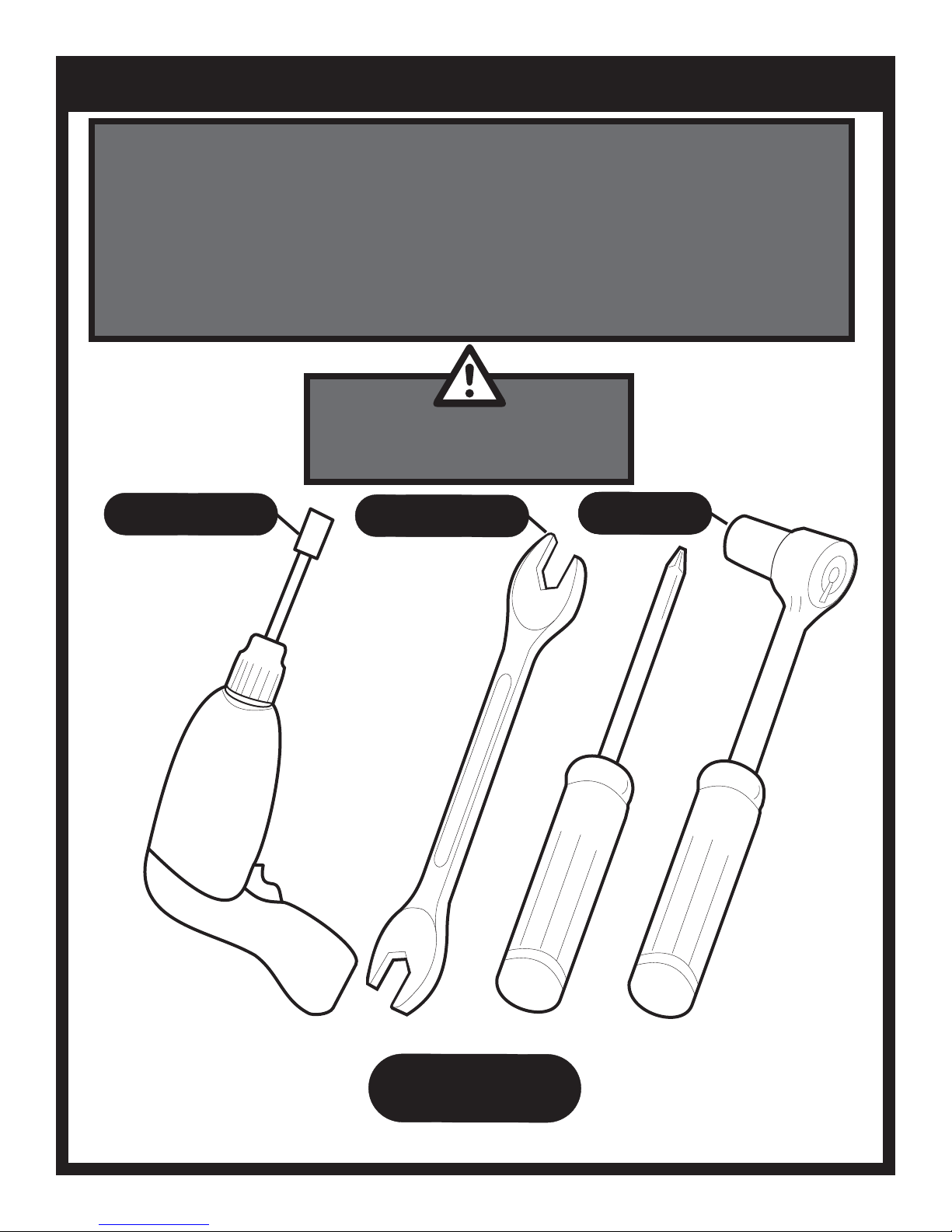
CAUTION:
Parts may have sharp edges. For your safety
wear leather work gloves and handle parts
carefully during unpacking and assembly.
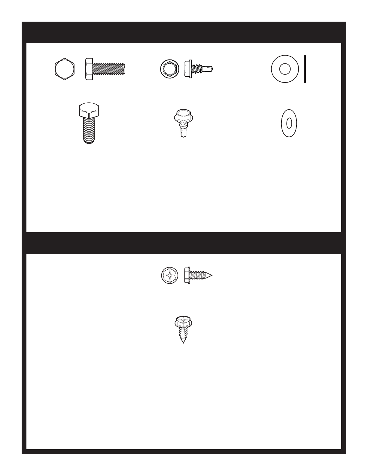
3/8” and 7/16”
3/8” and 7/16”
5/16”
REQUIRED
3/8”, 7/16” and 3/4”
REQUIRED
3/8” and 7/16”
REQUIRED
REQUIRED
REQUIRED
B102227-4-0615 Page 5
TOOLS
REQUIRED
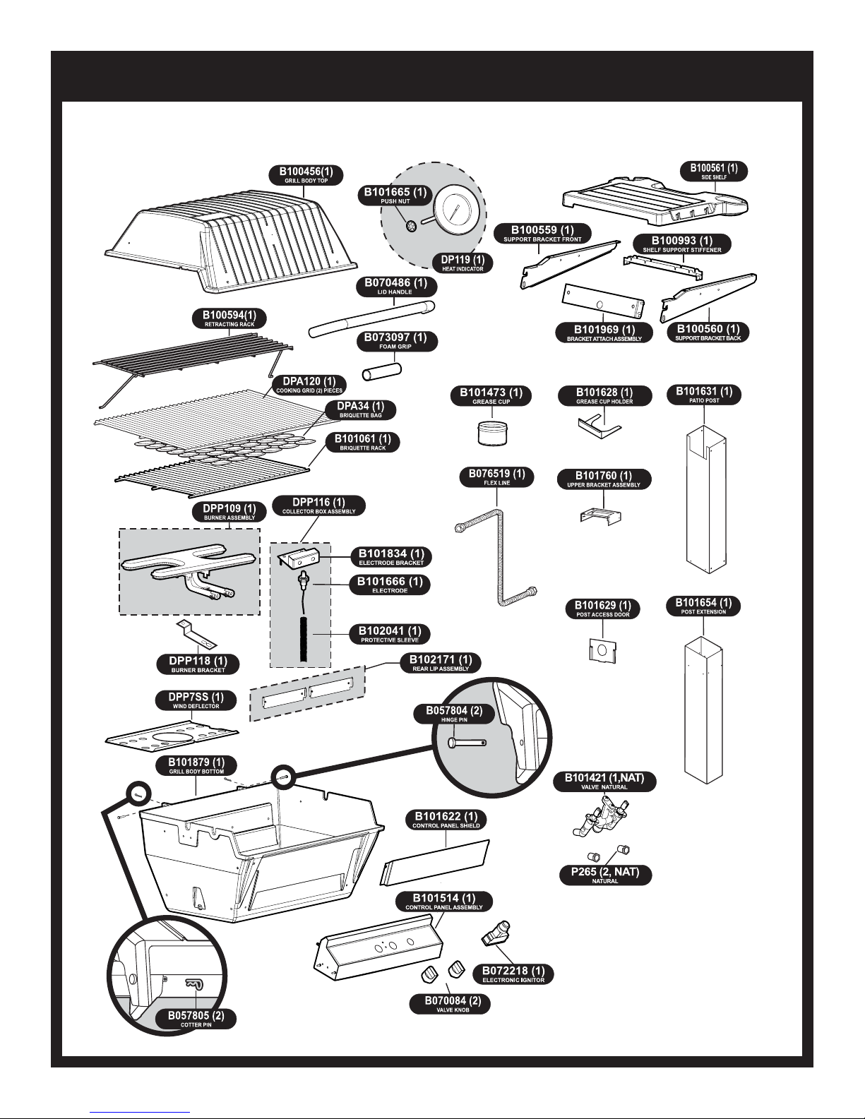
H3PK2 SERIES PARTS DIAGRAM
B102227-4-0615Page 6
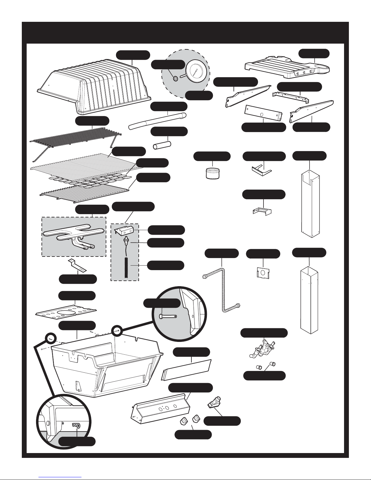
H4PK2 SERIES PARTS DIAGRAM
B060757 (1)
RETRACTING RACK
DPP115 (1)
BURNER ASSEMBLY
B076621 (1)
GRILL BODY TOP
DPA114 (1)
COOKING GRID (2) PIECES
DPA34 (1)
B067449 (1)
DPP116 (1)
COLLECTOR BOX ASSEMBLY
B101665 (1)
B070486 (1)
LID HANDLE
B073097 (1)
FOAM GRIP
BRIQUETTE BAG
BRIQUETTE RACK
PUSH NUT
DP119 (1)
HEAT INDICATOR
B101473 (1)
GREASE CUP
B100559 (1)
SUPPORT BRACKET FRONT
BRACKETATTACH ASSEMBLY
UPPER BRACKET ASSEMBLY
UPPER BRACKET ASSEMBLY
B101969 (1)
B101628 (1)
GREASE CUP HOLDER
B101760 (1)
B101760 (1)
B100561 (1)
SIDE SHELF
B100993 (1)
SHELF SUPPORT STIFFENER
B100560 (1)
SUPPORT BRACKETBACK
B101631 (1)
PATIO POST
DPP118 (1)
BURNER BRACKET
DPP7SS (1)
WIND DEFLECTOR
B101443 (1)
GRILL BODY BOTTOM
B101834 (1)
ELECTRODE BRACKET
B101666 (1)
ELECTRODE
B102041 (1)
PROTECTIVESLEEVE
B057804 (2)
HINGE PIN
CONTROLPANELASSEMBLY
B101621 (1)
CONTROLPANELSHIELD
B101515 (1)
B076519 (1)
FLEX LINE
B101629 (1)
POST ACCESS DOOR
B101421 (1,NAT)
VALVENATURAL
P245 (2,NAT)
NATURAL
B101654 (1)
POST EXTENSION
B057805 (2)
COTTER PIN
B102227-4-0615 Page 7
B070084 (2)
VALVE KNOB
B072218 (1)
ELECTRONIC IGNITOR
POST HARDWARE PACK - B101999
HEX HEAD BOLT,
SS,1/4-20 X 3/4
B063096
(4)
SELF-DRILLING
HEX HEAD SCREW,
SS,10-24 X 1/2
B101569
(5)
POST HARDWARE PACK - B102055
FLATWASHER,
SS,1/4 ID X 5/8
OD
B076332
(4)
Standard hardware items such as bolts, screws, washers, and nuts can be purchased at your local hardware store. Do not order individual pieces of standard hardware. A replacement hardware pack may be
ordered using the hardware pack part number at the top of the page.
SELF-DRILLING
HEX HEAD SCREW,
10-24 X 1/2
R2737
(8)
B102227-4-0615Page 8
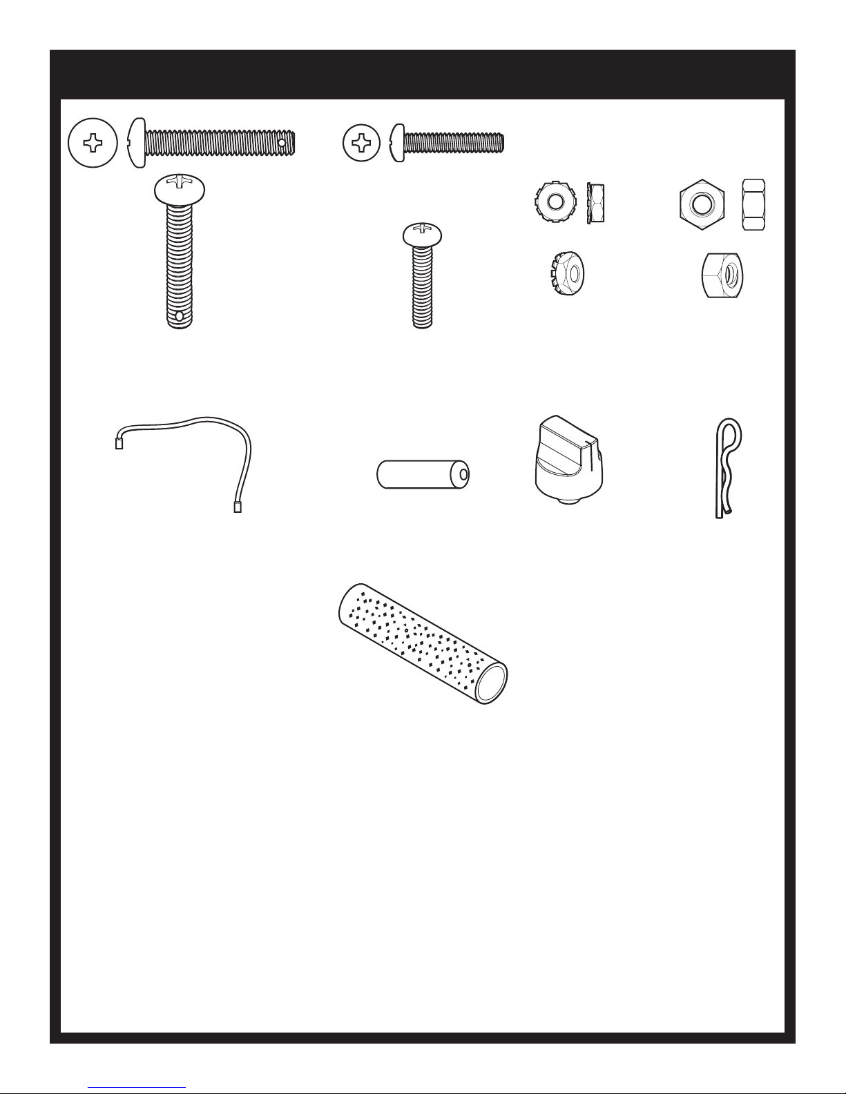
GRILL HEAD HARDWARE PACK - B102153
PHILLIPS PAN HEAD SCREW,
SS,1/4-20 X 1-1/2
B101649
(1)
GROUND
WIRE
B072684
(1)
PHILLIPS PAN HEAD SCREW,
SS,10-24 X 1
B073978
(2)
BATTERY, AA
B076529
(1)
FOAM GRIP
B073097
(1)
KEPS NUT,
SS,10-24
B073967
(2)
KNOB
B070084
(2)
HEX NUT,
SS,1/4-20
B076331
(1)
COTTER PIN
B057805
(1)
Standard hardware items such as bolts, screws, washers, and nuts can be purchased at your local hardware store. Do not order individual pieces of standard hardware. A replacement hardware pack may be
ordered using the hardware pack part number at the top of the page.
B102227-4-0615 Page 9
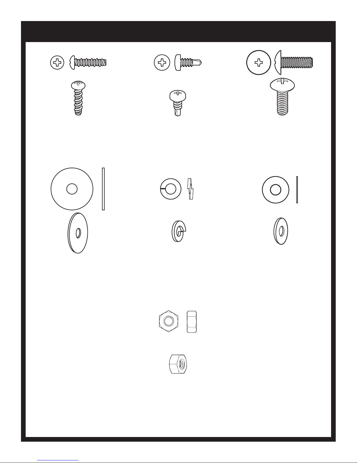
SHELF HARDWARE PACK - B101658
PHILLIPS PAN HEAD SCREW,
10-16 X 3/4
B100563
(4)
FLATWASHER,
SS,1/4 ID X 1
OD
B101640
(2)
SELF-DRILLING PHILLIPS PAN HEAD SCREW,
SS,10-16 X 1/2
R4059
(2)
LOCK WASHER,
1/4 ID X 1/2 OD
B076333
(2)
PHILLIPS TRUSS HEAD SCREW,
SS,1/4-3/4
B072217
(2)
FLATWASHER,
1/4 ID X 5/8 OD
B076332
(2)
Standard hardware items such as bolts, screws, washers, and nuts can be purchased at your local hardware store. Do
not order individual pieces of standard hardware. A replacement hardware pack may be ordered using the hardware
pack part number at the top of the page.
HEX NUT,
SS,1/4-20
B076331
(2)
B102227-4-0615Page 10
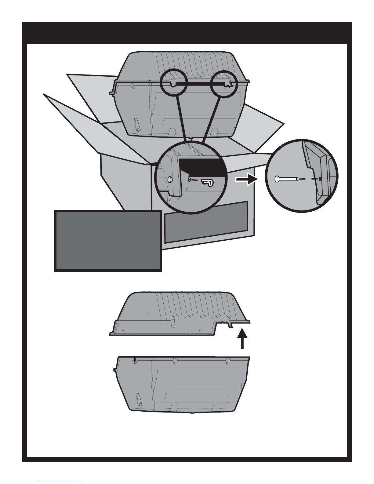
UNPACK AND REMOVE LID
REMOVING LID
To ease assembly, remove Grill Lid
and Warming Rack. Remove Warming
Rack and set aside. Remove the two
Pins and Clips at the rear of the Grill
Lid and set aside. After Pins, Lid and
Warming Rack have been removed,
remove the contents from inside the
Grill.
BROILMASTER
PREMIUM GRILLS
B102227-4-0615 Page 11
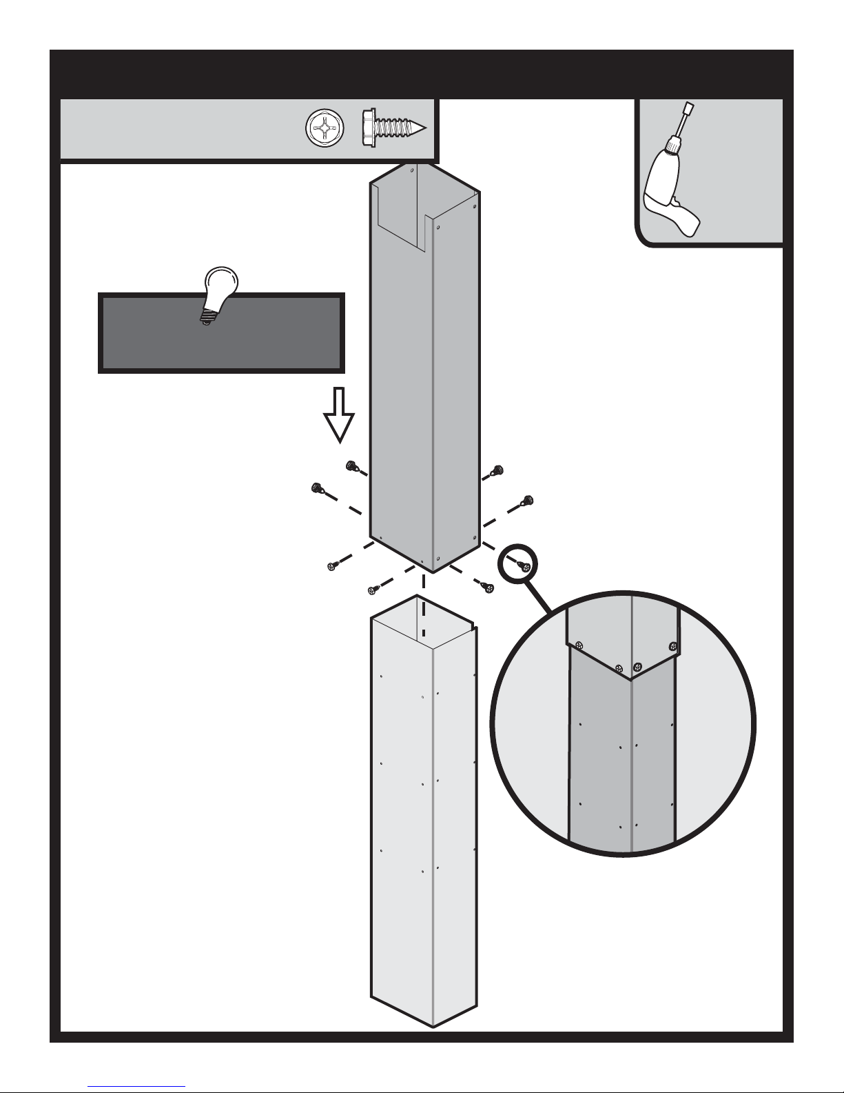
ATTACH EXTENSION POST ASSEMBLY
SELF-DRILLING HEX HEAD SCREW,
10-24 X 1/2
R2737 (8)
Locate rectangular cut-out at front of
post near the top.
5/16”
B102227-4-0615Page 12
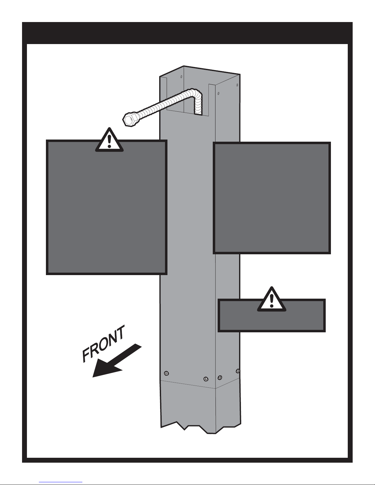
INSERT FLEX LINE THROUGH POST
Arrange with your local gas company or
licensed contractor to have a gas supply
line connected to inlet of stainless steel
flex tube assembly.
The gas supply line should be installed
according to local codes to prevent
damage from digging.
CAUTION: The gas supply line must be
regulated (In the case of Natural gas that
means connected after your gas meter and
regulator) and that you have an easily
accessible shut-off valve.
WARNING: Do not SUPPLYLP GAS to a
grill designed for NATURAL GAS or
NATURAL GAS designed for LP GAS.
At the access door connect a 3/8" flare
coupling (not supplied by Empire) to the
gas supply line and stainless steel
tubing. Position the tubing in the top
notch of the post. Bend the flex tube at
the top end to match the Feed Line of the
grill valve.
Note: Use pipe thread sealant or Teflon
tape at the threads of each connection
being careful to not allow any of these
materials into the flare seat. Test for gas
leaks as directed by the grill's Owners
Manual
B102227-4-0615 Page 13
Do not attempt to cut or alter the flex
tube in any way.

NATURAL GAS GRILLS
Grill Location
This grill is designed for outdoor use only.
Never operate your grill in any building, garage, or other
enclosed area. Never operate your grill in a recreational vehicle
or boat. Never operate your grill under any combustible materials,
such as carports, covered porches, awnings, or overhangs.
CAUTION
Keep the sides of the grill at least 16 inches from any
combustible material. Keep the back of the grill at least
18 inches from any combustible material. Placing a hot
grill too close to a building or other combustible mate-
rial may lead to re, property damage, or personal injury.
Combustible materials include fences, patio furniture,
and your home.
Keep the area around the grill clear to ensure proper ventilation.
WARNING
Do not install or operate this grill where gasoline or other
ammable materials are used or stored. Failure to comply
with this warning could result in explosion or re causing
property damage or personal injury.
Gas Type
The type gas required for your grill can be determined from the
product identication label located on the grill’s control panel.
Questions regarding different types of gases should be directed
to your local gas supplier.
Connection Requirements
Broilmaster natural gas grills are not equipped with pressure
regulators. Your gas grill operates at a manifold pressure of
seven inches water column. (Your natural gas technician will
understand what this means.)
Arrange with your local gas company or licensed contractor to
have a gas supply line connected to the inlet of the stainless
steel ex tube assemble. The gas supply must have a shutoff
valve that is close to the post in case of emergency and must
be shutoff when the grill is not in use.
Connect your grill this coupling using the twelve foot exible
hose with a quick disconnect tting (available for purchase from
your Broilmaster dealer.)
CAUTION
The grill and its individual shutoff valve must be discon-
nected from the gas supply piping system during any
system pressure testing at test pressures in excess of
1/2 PSIG.
CAUTION
The grill must be isolated from the gas supply piping sys-
tem by closing its individual manual shutoff valve during
any pressure testing of the gas supply piping system at
test pressures equal to or less than 1/2 PSIG.
CAUTION
Never use Liquid Propane (LP) gas in a grill designed
for Natural gas, or Natural gas in a grill designed for
Liquid Propane gas. Questions regarding different types
of gases should be directed to your local gas company.
B102227-4-0615Page 14
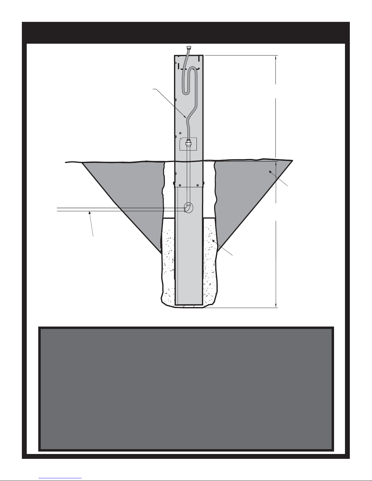
INSTALL POST IN GROUND
GAS SUPPLYLINE
FLEX LINE
(SUPPLIED BY
EMPIRE)
28-3/4”
ABOVE GRADE
SOIL GRADE
28-3/4” APPROX
DEPTH OF HOLE
CONCRETE OR
STANDARD
PRE-MIX
1. Dig a posthole approximately 12 inches in diameter and 28-3/4 inches in depth at the desired grill
location.
Note: "Normal Installation" height is achieved when the top of the 48 inch post is 24-3/4 inches above
ground. This height provides a cooking surface height of approximately 34 inches above ground.
2. Carefully lower the post into the hole using the following guidelines:
• The upper rectangular cut-out is located near the top of the post and should be above ground
after installation.
• The rectangular cut-out must face in the same direction as the front of the grill.
• Check hole depth and post measurements to ensure desired height.
Note: Make any adjustments at this time.
3. Use concrete pre-mix according to the manufacturer's package directions. Position the post in the
center of the hole. Use a level when aligning the post to achieve precise vertical alignment. Hold the post in
place while pouring the concrete mixture into the hole around the post. Keep concrete below gas line hole.
B102227-4-0615 Page 15
 Loading...