


Operating Manua l
with TPU Comfort Technology™
ClearPath Mobility
Register your warranty online at www.brodaseating.com
Distributor/Rep: This manual must
be given to the caregiver responsible
for this chair and its occupant.
Caregiver: Before using this chair,
read this manual thoroughly and save
for future reference.
ClearPath Positioning
OM-930.7.30.2012 www.seatingisbelieving.com www.brodaseating.com Email: sales@brodaseating.com
BRODA Seating
560 Bingemans Centre Drive
Kitchener, Ontario Canada N2B 3X9
Phone: 1-800-668-0637 Fax: 519-746-8616

Contents
FOREWORD ................................................................................................................................................................. 1
GENERAL INFORMATION ........................................................................................................................................ 2
1 DEFINITIONS ...................................................................................................................................................... 3
2 SAFETY REQUIREMENTS ................................................................................................................................ 4
2.1 Training ........................................................................................................................................................ 4
2.2 Application ................................................................................................................................................... 4
2.3 Shipping and Storage ................................................................................................................................... 4
2.4 Pre-Service Check ........................................................................................................................................ 5
2.5 Hazards ........................................................................................................................................................ 5
2.5.1 Position of Chair - “Danger of Falling” ................................................................................................... 5
2.5.2 Position of Seat Tilt - “Danger of Tipping” ............................................................................................. 5
2.5.3 Location of Chair - “Danger of Tipping or Falling Objects” ................................................................... 5
2.5.4 Total Lock Wheel Brakes - “Danger of Falling” ..................................................................................... 5
2.5.5 Re-Positioning of Resident - “Danger of Clamping” ............................................................................... 6
2.5.6 Unintended Mo vement - “Danger of Falling or Collision” ...................................................................... 6
2.5.7 Resident Clothing - “Risk of Injury to Re sident’s S kin” ......................................................................... 6
2.5.8 Improper Restraint Use - “Risk of Serious Injury” .................................................................................. 6
2.6 Improper Use................................................................................................................................................ 7
2.7 Cleaning ....................................................................................................................................................... 7
2.8 Maintenance ................................................................................................................................................. 9
2.9 Resident Specific Instructions .................................................................................................................... 10
3 OPERATION AND MOVEMENT ..................................................................................................................... 11
3.1 Seat Tilt ...................................................................................................................................................... 11
3.2 Back Recline (Optional on Mo bility, Standard on Positioning) ................................................................. 11
3.3 Elevating Leg Rest (Optional o n Mobility, Standard on Positioning) ........................................................ 12
3.4 Leg Rest Length Adjustment...................................................................................................................... 12
3.5 Wings (Optional on Mobility, Standard on Positioning) ............................................................................ 12
3.6 Armrest Height Adjustment ....................................................................................................................... 13
3.7 Armrest Dep th Adjust ment ........................................................................................................................ 14
3.8 Seat Depth Adjustment .............................................................................................................................. 14
3.9 Seat Height Adjustment ............................................................................................................................. 15
3.10 Casters ........................................................................................................................................................ 16
3.11 Back Recline Installation and Removal ..................................................................................................... 16
3.12 Elevating Legrest Installation and Removal .............................................................................................. 17
3.13 Swing Away Legrest Hanger Installation and Removal ............................................................................ 18
3.14 Push Bar Installation .................................................................................................................................. 18
3.15 Side Panel Installation ................................................................................................................................ 18
3.16 Accessories (Options) ................................................................................................................................ 19
3.17 Motor Vehicle Use (Vehicle Transport Package Option) .......................................................................... 19
INSPECTION AND FUNCTIONAL TESTING ........................................................................................................ 23
Functional Testing ................................................................................................................................................... 24
4 TECHNICAL INFORMATION .......................................................................................................................... 25
4.1 Specifications ............................................................................................................................................. 25
4.2 Labels ......................................................................................................................................................... 27
5 COMMON TROUBLESHOOTING AND REPAIR .......................................................................................... 28
5.1 Troubleshooting for Gas Cylinders ............................................................................................................ 28
6 WARRANTY ...................................................................................................................................................... 30
ii

FOREWORD
Congratulations on your purchase of a BRODA chair and thank you for your confidence in our
company and products.
BRODA assumes a leadership role in providing optimum re-positioning functions and mobility
for residents of long-term care institutions. Our chairs do not look like traditional chairs and offer
advantages unique to BRODA. We are sure that after using your BRODA chair, you will be
convinced that your resident’s quality of life will be greatly enhanced.
This manual will assist you in making the best use of the capabilities of your BRODA chair and
will ensure that you quickly become familiar with its operation.
After reading this manual, if you have any questions about the safe and effective operation of
your BRODA chair or accessories contact your local BRODA representative or our Head Office
Customer Service personnel for further assistance.
Head Office:
BRODA Seating
560 Bingemans Centre Drive
Kitchener, Ontario Canada N2B 3X9
Phone: (519) 746-8080 Toll Free Can/US: 1-800-668-0637
Fax: (519) 746-8616
E-mail: sales@brodaseating.com
URL: www.brodaseating.com www.seatingisbelieving.com
1

GENERAL INFORMATION
This document provides guidance on the safe and effective operation of the BRODA chair.
Information in this manual must be followed at all times.
Anyone involved with the operation or maintenance of the BRODA chair, including the
resident’s family members, must read this operating manual before using the chair.
The resident’s primary caregiver is responsible for ensuring that anyone who is unfamiliar with,
unwilling, or unable to adhere to the safety and operating instructions, is not permitted to operate
or move the chair.
A copy of this instruction manual must always be available.
BRODA accepts no liability for damages, injury or accidents caused by operating errors,
improper maintenance, or disregard of the instructions in this manual, including any resident
specific instructions.
BRODA reserves the right to make changes to the specifications, dimensions, functions, or
components of its products without notice. Product representations in this manual may vary from
delivered products.
Each BRODA chair has a unique identifying serial number that must be maintained on the chair
as well as with any equipment records.
2

1 DEFINITIONS
“BRODA” means BRODA Enterprises Inc. do ing busines s as BRODA Seating.
“BRODA chair” refers to ClearPath™ model.
“Long-Term Care Institution” refers to a nursing home, hospital, or other healthcare facility that provides health and
personal care to its residents on a long-term basis.
“Resident” refers to an individual living in a long-term care instituti on under the care of professional caregivers.
“Professional Caregiver” refers to doctors, nurses, therapists, nursing aids, healthcare aids, and other specialists who
work in a long-te rm care institution and provide health and per so nal ca re to its residents.
“Caregiver” refers to any person in a long-term care institution who is appropriately trained to provide care or
services to the resident or the chair used by the resident and may include the resident’s family members or guardian.
“Seat Tilt” refers to changing the relative angle between the chair’s seat and the chair fr ame or ground without
changing the relative angle between the back and the seat.
“Back Recline” refers to changing the relative angle between the chair’s back and the seat.
“Footrest Elevation” and “Leg Rest Elevation” refers to changing the relative angle between the chair’s footrest
and/or leg rest and the seat.
“Transfer(s)” refers to the movement of a resident into or out of the chair with the assistance of their caregiver(s).
“Mechanical Transfer(s)” refers to the movement of a resident into or out of the chair with the assistance of their
caregiver(s) using a patient lift or other assistive device that bares the weight of the resident.
3

2 SAFETY REQUIREMENTS
2.1 Training
Before the chair is put into service, this manual must be read thoroughly by the caregiver(s) directly
responsible for the resident’s care.
After the chair is put into service, this manual must be re ad thoroughly by any new caregivers prior to
operating or moving the chair.
For the purpose of this manual, a resident’s family member who shares responsibility for their care is considered a
caregiver and is subject to the same competency before being permitted by the resident’s primary caregiver to
operate of move the chair.
Prior to first use, the customer must arrange for an in-service on the operation and safety requirements in this
manual, must be given to the resident’s caregivers by the local BRODA representative who supplied the chair.
The primary caregiver must maintain a list of caregivers who have read this manual and who they have authorized to
operate and move the chair.
The resident’s primary caregiver is responsible for ensuring that anyone who is unfamiliar with, unwilling, or unable
to adhere to the safety and operating instructions, is not permitted to operate or move the chair.
The operations of the chair must be performed by the resident’s primary caregiver who is responsible for seating. All
The operations and adjustments performed should be done in a manner to ensure the overall safety, comfort and
well-being of the resident, caregiver and thi rd party. All operations and adjustments required for the resident should
be determined by the resident’s primary caregiver who is responsible for seating.
2.2 Application
BRODA chairs are intended exclusively for residents of long-term care institutions who are under the care of
professional caregivers. The suitability of a BRODA chair must be determined by a qualified caregiver who is
familiar with the s eating needs of the intended resident. A ny other use of the chair is excluded from possible liability
claims.
ClearPath is a 2 in 1 mobility and positioning chair designed to accommodate a wide spectrum of needs with
adjustments that are performed at the factory or in the field.
ClearPath is not to be used in the shower. The frame and components will rust, and will void the warrant y.
The chairs are not explosion resistant and must not be used where there are flammable gases or liquids present (e.g.,
anesthetics, volatile solvents and cleaners, etc.)
BRODA chairs are designed for use with specific BRODA parts and accessories. The use of non-BRODA parts or
accessories with a BRODA will void the warranty and is excluded from possible liability claims.
BRODA chairs may only be used as de s cribed in this manual and with proper r egard for recognized healthcare and
workplace safety and accident prevention practices.
2.3 Shipping and Storage
BRODA chairs should be shipped and stored in an upright position and not stacked higher than 3 boxes. No other
materials should be shipped or stored on top of a BRODA box. BRODA boxes should not be placed on pallets.
4

BRODA chairs should be shipped and stored at temperatures between -20ºC and 40ºC. BRODA chairs should not be
used until they are between 0ºC and 30ºC.
BRODA chairs should be kept in a clean, dry environment. Do not leave BRODA chairs outdoors as it may cause
the paint to peel.
Upon receipt, the shipping carton must be immediately examined for damage. Any damage should be noted on the
delivery receipt and a request for inspection by the transportation company should be made. Next, the shipping
carton should be opened and the chair must be examined for concealed shipping damage. If the chair appears to be
damaged, do not use the chair. File a concealed damage report with the transportation company.
2.4 Pre-Service Check
BRODA chairs are delivered full y assembled. If the chair does not appear to be ready to use upon receipt,
immediately contact your supp lie r a nd do not put the chair into service until any concerns have been resolved.
Visually inspect the chair for damage, missing parts, and loose fasteners p rior to testing the chair’s functions.
Functional testing must be successfully completed after visual inspection and before use. These obligations apply to
the chair’s first use and to all subsequent uses (Section 4: Inspect ion and Functi onal Testing).
2.5 Hazards
2.5.1 Position of Chair - “Danger of Falling”
Immediately after a resident is transferred into a chair, we recommend that the chair’s seat be tilted sufficiently to
prevent the resident from sliding or falling fo rward off the chair. The amount of seat tilt used should be determined
by the resident’s caregiver who is responsible for seating.
On ClearPath models in which a legres t is included, we recommend that the resident’s feet be correctly positioned
on the footplate a nd slig htly to fully elevated when applicable, to prevent the resident from sliding or falling forward
off the chair. The amount of elevation used should be determined by the resident’s caregiver who is responsible for
seating.
2.5.2 Position of Seat Tilt - “Danger of Tipping”
We recommend that the chair’s seat be tilted sufficiently to prevent the resident from tipping the chair forward or
backward, or from slumping and sliding in the chair. The amount of seat tilt used should be determined by the
resident’s caregiver who is responsible for seating. Always ensure that the resident is properly positioned before
operating the seat tilt.
2.5.3 Location of Chair - “Danger of Tipping or Falling Objects”
We recommend that when a resident has been moved to their destination, the chair is placed where the resident
cannot reach handrails or other objects, fixed or movable. This is to prevent the resident from pulling the chair over
or pulling themselves off the seati ng surface and to prevent the resid ent from pul ling movable objects onto the chair
and themselves.
We recommend that the chair be used in a supervised area to prevent untrained residents, caregivers, or third parties
from unaut horized operation, movement, or uns afe actions such as sitting or lea ning on the reclined back, elevated
footrest, or the armrests. These a c tions, if not prevented, put the chair at risk of tipping or damage to the chair.
We recommend that a chair only be located on a level surface to minimize the risk of tipping over.
2.5.4 Total Lock Wheel Brakes - “Danger of Falling”
The special casters found on the BRODA chair ha ve total lock brakes which prevent t he wheels from turning and
swiveling. The brakes must always be applied when:
1) the chair is not in use;
2) a resident is being transferred (moved) into or out of the chair; and,
3) the chair is not being moved by a caregiver or being self propelled by the resident
5

It is important to note that if the brakes are applied while the resident is in the chair, that the caregiver does not leave
the resident unattended, especially those residents who have the capability or tendency to move the chair and/or
those who may be agitated. This could cause harm to the resident if they attempt to move the chair while the brakes
are applied.
Failure to follow these instructions will unnecessarily increase the risk of serious falls by residents, caregivers, or
third part i es caused b y the chair uni ntentional ly moving.
2.5.5 Re-P ositioning of Resident - “Danger of Clamping”
BRODA chairs offer the benefits of seat tilt, back recline, leg rest/footrest ele vatio n, and moveable arms. During the
movement of any of these functions, the following safety measures must be observed:
1) The resident’s arms must be positioned on the armrests or inside the chair frame with their ha nds
on their body.
2) The resident’s feet must be c orrectly positioned on the footrest.
3) All of the chair’s brakes have been applied.
4) Only one caregiver at a time attempts to operate the chair’s functions.
5) Only one chair function is operated at a time.
6) The rear wheels are in the trailing position, behind the chair frame.
7) The residents’ and caregivers’ body are clear of all pinch points before operating the chair’s
functions.
Failure to follow these safety measures can put the residents’ or caregivers’ limbs at risk of injury. Residents who
may be unaware of their body position or unable to maintain a safe body position are at the most risk of the danger
from clamping and caregivers should be more cautious with these residents. A second caregiver may be required to
ensure the safety of these residents during these operations.
2.5.6 Unint ended Movement - “Danger of Falling or Collision”
We recommend BRODA chairs for indoo r use within a long-term care institution and wher e there is not e nough
slope to cause the chairs to move unaided. Chairs used where the surface is uneven or sloped are at risk of
unintended movement and could become a serious danger to the resident, caregiver(s), or a third party. We
recommend that BRODA chairs are located away from stairwells, elevators, and exterior doorways with i n a longterm care institution.
Outdoor use is appropriate only under the strict supervision and full attention of a caregiver who is physically
capable of preventing any unintended movement over any surfaces that are to be traveled on. We recommend that a
second caregiver assist when the chair is moved over surfaces that could cause significant unintended movement.
2.5.7 Reside nt Clothing - “Risk of Injury to Resident’s S kin”
We recommend that residents only be seated while they are fully dressed in clothing that meets the needs of their
specific condition. If after being f ully dressed, a resident’s bare arms, legs, o r body could still come into direct
contact with the TPU seating surface (Thermoplastic Polyurethane) or vinyl pads, we recommend the use of a
covering, s uch the BRODA terry cloth covered seat and/or back pad or a folded cloth bed sheet to prevent direct
contact. Direct contact of bare skin on the uncovered seat and back surface over a period of time could cause
moisture on the resident, and/or cause the ski n t o stick to the surface. Prior to the operation or movement of a chair
with a covering, the caregiver must ensure any covering placed on the chair does not come into contact with any
moving parts and is securely placed, so not to slip.
2.5.8 Improper Restraint Use - “Risk of Serious Injury”
We recommend that alternatives to physical restraints be used with residents while seated in the chair except under
the specific instructions of the resident’s primary ca regiver a nd with permi s sion of the resident’s family or guardian.
Physical restraints have been identified as a common cause of serious injury to residents while they are seated. We
recommend that the primary caregiver responsible for seating first consider the re-positioning options available in
the chair to reduce the risks of slidin g, falling, or self-injury.
If a physical restraint is determined to be appropriate to prevent sliding or falling out of the chair, we recommend
that the BRODA thigh belt be used. In all cases, it is the resident’s primary caregiver that must take responsibility
for the safety of the resident if restraints are used.
6

2.6 Improper Use
As outlined , the improper use of the chair is dangerous to the resident, caregivers, or third parties, and can consist of,
but is not limited to the following:
1) Unauthorized operation of the chair’s functions.
2) Unauthoriz ed movement of the chair.
3) Inappropriate use of the chair for a resident who has not been assessed by a qualified caregiver
responsible for their seating.
4) Failure to frequently reposition the resident in the chair
5) Attempting to operate of multiple chair functions simultaneously by one or more caregivers.
6) Attempting to move the chair with the brake(s) applied.
7) Leaving the resident unattended in the chair near other objects.
8) Leaving an agitated resident in the chair in an unsupervised area.
9) Leaving a resident unattended.
10) Leaving a resident in a chair on a sloping surface.
11) Leaving a chair unattended on a sloping surface.
12) Using non-BRODA accessories on the chair.
13) Using the chair at temperatures below 0ºC.
14) Using the chair as a shower or bathing chair.
15) Using the cha i r for any use other tha n i ts intended purpose.
2.7 Cleaning
BRODA chairs should b e wiped clean with soap and water. Diluted household strength ammonia or chlorine based
cleaner, as well as a hospital grade cleaner may be used if necessary.
Refer to the following guide for cleaning certain staining agents (Applies to the Permablok3® vinyl , as per the vinyl
manufacturer’s recommendations) The frame and components of the chair can be cleaned using the same procedure
as the vinyl.
The steps below are also located in the Cleaning Guide found on the back of the Broda chair
Staining Agent Cleaning Procedure
Eye Shadow / Mascara Step 1
Grease / Suntan Lotion / Chocolate Step 1
Blood / Bodily Fluids Step 2
Red Lipstick Step 2
Oil Base Paint / Tar / Asphalt Step 3
Other Tough Stains Step 4 or 5*
Step 1: Remove excess spill with a damp cloth. Clean with a 1 :1 mix of Ivory® liquid and water. Rinse with clean
water and dry.
Step 2: Use a straight application of concentrated cleaners such as Formula 409® or Fantastik® Spray Cleaner.
Then wipe with a clean cloth. If usin g a hosp ita l grade cleaner, follo w the diluti ng instructions on the label.
Step 3: Use a 1:1 mix of ammonia and water or a 1:4 mix of bleach and water. Rinse with clean water and dry.
Step 4: Use a straight application of nap htha (lighter fluid). Rinse thoroughly with clean water and pat surface dry.
Step 5: Use a 1:1 mix of isopropyl alcohol and water. If the stain persists, use straight alcohol. Rinse thoroughly
with clean water and pat dry. If the stain remains, use a 1:1 mix of acetone and water. Rinse with clean water and pat
surface dry.
*Note: for cleaning that requires steps 4 or 5 – Use a soft cotton cloth saturated with the cleaning material and rub
the stain in circles 10 times. Pat dry with another soft cotton cloth, and check resul t s .
7

Ensure that the entire chair including removable and non removable parts is thoroughly cleaned.
Pay close attention to the frame, fasteners, parts and casters, as well as the padding for an even, thorough clean.
BRODA chairs should not be cleaned with petroleum based cleaners. Any petroleum based products that come in
contact with any vinyl should be removed as quickly as possible. Petroleum based products make vinyl brittle and
will damage the cushions. Metal parts and cushions should be wiped completely dry after cleaning. Do not launder
vinyl padding. Terry cloth seat and back covers can be laundered and tumble dried. Neoprene pads (side pads, calf
and foot pad) should be laundered in cool water on gentle cycle with detergent such as Draft or Wo olite per
manufacturer’s spec.. Lay Neoprene pads or drape to dry.
Do not allow the chair to air dry. Leaving the chair to air dry and not ensuring the entire chair is completely dry may
cause the frame and components to rust. Solvents such as those found in spray lubricants should not be used on
BRODA Chairs as they can damage moving parts.
Frequency and method of cleaning the chairs should be determined by facility infection control protocols. If visibl y
soiled, thoroughly clean the chair immediately as per the cleaning instructions in this manual.
The cleaning instructi ons in this manual are guidelines only. Results may vary u nder actual conditions. The
information does not relieve the user of prop er and safe use of the product and all cleaning agents and consideration
for the overall cleaning maintenance of the chair. Cleaning and care instructions must be follo wed in conjunction
with facility infection control protocols.
BRODA will not accept warranty or liability claims on chairs that have not been cleaned according to the
instructions or cared for in proper regard for patient, caregiver and third party safety and hygiene.. The use of certain
agents may be harmful to the surface appearance and lifespan of the vinyl. BRODA assumes no responsibility
resulting fr om the use of such clea ning agents to the vinyl.
Touch up paint is available for the powder coated frame. Please call Broda’s Customer Service Department if touch
up paint is required. Do not leave BRODA chairs outdoors as the frame is not UV protected. Leaving the chairs
outdoors could cause the paint to peel.
Formula 409® is a trademark of the Clorox Company.
Fantastik™® is a trademark of Do wBrands, Inc.
Trademark of the Dow Chemical Company.
Ivory® is a trademark of Proctor and Gamble.
8

2.8 Maintenance
The maintenance on a BRODA chair will vary with the amount of use and the condition of the resident using the
chair.
In regular use, after the initial inspection and functional testing, the chair should be inspected and tested bimonthly.
We recommend visually inspecting for signs of wear, damage, loose or missing fasteners, and other safety concerns.
Periodic testing of chair functio ns is also necessary. If a breakage, defect, or operational problem is detected, the
chair must be successfully repaired, inspected and tested for function before it is returned to service.
The chair should be inspected and tested as often as each use if the chair is used by:
1) Aggressive or agitated residents.
2) Residents who ha ve invo lu ntary movement s.
3) Residents weighing over 220 lbs.
4) A facility with irregular or sloped surfaces.
5) Any unauthorized person.
Do not use lubricants tha t contain solvents. Solvents may compromise any rubber components on the chair. If
necessary, white food grade grease or lubricant can be used on any sliding components.
9

2.9 Resident Specific Instructions
The primary caregiver responsible for the specific resident’s seating s hall add additional instructions necessary for
the safe and effective use of the chair based on their professional experience and kno wledge of the resident’s
specific conditions and requirements.
BRODA representatives are not professional caregivers and will not know the specific requirements of the
individual using the chair. BRODA relies on the knowledge, experience, and judgment of the resident’s professional
caregiver to ensure the specific resident’s safety and comfort needs are satisfied while using the chair.
These instructions form an essential part of the Safety Requirements for using the chair and must be made available
to all caregivers. Space is provided below to include these instructions.
BRODA Enterpr i ses Inc.
560 Bingemans Centre Drive
Kitchener, Ontario Canada N2B 3X9
Phone: 1-519-746-8080 Toll Free Can/US: 1-800-668-0637
Fax: 1-519-746-8616
Email: sales@brodaseating.com
URL: www.brodaseating.com www.seatingisbelieving.com
10

3 OPERATION AND MOVEMENT
Gas cylinders allow the seat to be tilted to any position
The back recline mechanism allows the back to be
Safety measures as described in Section 1 must be observed when operating the chair’s functions or movin g the
chair. To reduce personal injury, only authorized caregivers should attempt to operate or move a chair. The
caregiver must use proper body mechanics when operating the chair, and be prepared to support the weight of the
resident while operating the chair.
Note: Product images may look sli ghtly different than ac tual models.
3.1 Seat Tilt
from most upright to the lowest wit hin i ts ra nge. Use
seat tilt to safely position the resident, redistribute
pressure, increase comfort and assist with daily care
activities.
To Activate the Seat Tilt
-Place your hand on the tilt bar to assist movement and
squeeze the tilt handle with your other hand. Tilt
bar/handle location will depend on model. The tilt
handle is indicated by the tan label.
-Raise or lower the seat tilt until the desired angle is
achieved.
-Release handle.
3.2 Back Recline
reclined to any position from the most upr ight to the
lowest within its range. Use back recline to safely
position the resident, r e distribute pressure, increase
comfort, and assist with daily c a r e a c tivities.
Always tilt slightly before reclining to prevent
resident from sliding.
To Activate the Back Recline:
-Place your hand on the top b a r to assist movement and
squeeze the recline handle wit h your other hand while
pulling back to activate recline.
-Raise or recline the back until the desired angle is
achieved.
-Release handle.
(Optional on Mobility, Standard on Positioning)
11
Gas cylinders allow the leg rest to be positioned
The ClearPath leg rest is length adjustable from 17” to
Wings provide upper lateral support to the resident.
fastener plate.
3.3 Elevating Leg Rest (Optional on Mobility, Standard on Positioning)
infinitely from horizontal to vertic a l. The leg rest is
independently adjusta ble from the back recline.
To Elevate the Leg Rest:
-Hold leg rest to assist movement and squeeze the leg
rest handle.
-Raise or lower the leg rest to the desired angle.
-Release handle.
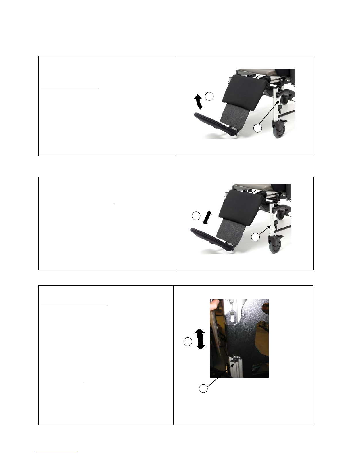
3.4 Leg Rest Length Adjustment
24” (from top of seat) to accommodate various residents.
To Adjust the Leg Rest Length
-Squeeze the leg rest length adjus tment handle .
-Extend or retract the leg rest to the desired length.
-Release handle.
3.5 Wings (Optional on Mobility, Standard on Positioning)
To Adjust the Wing Height:
-Loosen the wing nut located on the bottom of the
wing. Do not remove the wing.
-Adjust the wing ver tic al l y a long the back cane to
achieve desired position. Adjust from the bottom
keeping the wing aligned wit h the win g nut a nd key
hole bolt.
-Tighten wi ng n ut.
To Remove Wi ng:
-Loosen the wing nut loc ated on the bottom of the
wing.
- Lift the wing up to release from the key hole in the
12

-Remove wing
The armrests are height adjustable from approximately 8
To Attach the Wing:
-Position the wing against the fastener plate on the back
cane, lining up the bol t in the top of the key hole and
the wing nut in the bottom cutout.
-Raise or lower the wing to the desired position.
-Tighten wing nut.
3.6 Armrest Height Adjustment
¾” to 13 ¼” to accommodate various users. Low
mounted position range is approximately 8.5” to 11.5”.
High mounted position range is approximately 10” to
13”.
To Adjust the Armrest Height:
-Turn the dial on the outside of the armrest assembly in
the desired direction to raise or lo wer the armrest.
Ensure it locks into place.
-To change the armrest mounting position, to achieve a
different height range, remove the 2 bolts from the
armrest mounting bracket
-Reinsert the bolts into the new position in the mounting
bracket and into the mounting block and tighten.
WARNING: Do not place fingers or any part of the
body under the armrest or near the armrest height
adjustment mechanis m as this could cause pinching.
13

The armrests are depth adjustable to accommodate
The seat depth is infinitely adjustable from 15” – 21” by
Recline Model
3.7 Armrest Depth Adjustment
various residents as well as accommodate changes in
seat depth.
To Adjust Armrest Depth:
-Remove the 2 bolts from the armrest bracket
-Move the armrest and mounting block along the seat
frame to the desired position.
-Re-insert the armrest bolts throug h the armrest
mounting br acket and the through the mounting block
and attach to desired position along the seat frame.
-Tighten bolts.
3.8 Seat Depth Adjustment
moving the back along the seat frame.
-Loosen the bolt on each side of the back recli ne plate
(and the 2 bolts on the seat recline plate if applicable ),
with the appropriate wrench.
-Standing behind the chair, move the back forward or
backward to the desired position. Refer to the
measurements on the seat rail to indicate the seat depth
position. Carefully adjust each sid e slightly at a time to
assist the movement of the back along the frame.
Ensure that the back is adjusted to the same position
on both sides by referring to the measurements on
the seat rail.
-Tighten bolts.
14

3.9 Seat Height Adjustment
The seat height is adjustable to accommodate various
Side Rail
Short Caster Posts
Long Caster Posts
Side Brace Rail
Side Rail
Back Brace
users.
Height adjustment ranges from 13” -17” with short
casters posts; 18” -21” with long caster posts.
To Adjust Seat Height:
-Turn chair on its side to remove caster posts and screws.
-Re-position posts to desired height or install new posts
(short or l ong) depend ing on desired seat height. See
Installing Caster Posts instructions below.
-For seat height range of 18” -21” (long caste r posts),
lower side brace rails must be installed.
To install side brace rails, once caster posts have been
installed to desired position, bolt the side brace rails from
front to rear caster at the bottom of the caster post.
Installing Caster Posts:
-Turn chair on its side to remove caster posts and screws.
-Un-bolt the casters and remove from the posts (and side
brace rails if applicable)
-Bolt casters on to the new caster posts (bolt front to
back through the bottom hole on the caster post)
-Bolt the 4 new posts through the side rails (2 bolts on
each end) at the desired height. Hand tighten. Ensure all
posts are bolted to the side rails at the same height to
ensure chair is level.
-Side brace rails are required with long caster posts. If
applicable, bolt the side brace rails to the caster posts
through the caster bolt with the longer bolts provided.
Hand tighten. A back brace rail may apply (standard on
chairs with a 22” or 24” seat width and chairs with
optional 350 lb. weight capacity.) Ensure the back brace
rail is installed if applicable.
Installing the Back Brace Rail:
-Remove the bottom bolt from both rear casters.
-Install the back brace rail onto the rear caster posts into
the bottom hole using the longer bolts provided.
-Ensure all bolts are tightened before use.
15

3.10 Casters
ClearPath Positioning models feature three 5” total lock
ClearPath offers optional back recline for additional
the upper cross bar in the holes provided.
Recline Handle
Push Bar
Recline Plate
casters and one 5” directional locking caster (different
colour pedal) ClearPath Mobility models feature two 5”
total lock casters and two 5” fixed locking casters.
The tracking and fixed casters allow for easy
maneuverability.
To Operate the Casters:
Step on/off the pedal to lock/unlock the caster.
Always ensure the brakes are unlocked when
wheeling the chair.
For chairs with mag wheels, lock and unlock using the
handbrakes.
3.11 Back Recline Installation and Removal
positioning.
To Install the Back Recline:
-Install the push bar on t he back of the chair if
applicable. (See Push Bar Installati on Instructions)
-Remove the back from the seat by detaching the fixed
recline plates from the seat. Before fully removing the
back, disconnect the seat tilt handle from the back frame.
-Attach the seat recline plates to the seat frame in the
same location from which the fixed recline plates were
removed. Refer to the measurements on the seat rail to
indicate the seat depth positio n.
-Remove the fixed recline plates from the back.
-Attach the recline plates to the back in the same
position from which the fixed recline plates were
removed from the back.
-Re-attach the back to the seat frame by attaching the
back recline plates to the seat recline plates.
Ensure that the back is a djusted to the same position
on both sides by referring to the measurements on
the seat rail.
-Install the recline cylinder(s) to the seat recline plate
and the push bar with the actuator facing upward. The
cable should be attached to the actuator. (One or two
cylinders may be installed).
-Attach the recline cable handle to the left hand side of
Fixed Recline Plate
Seat Recline Plate
16

-Attach the tilt cylinder to the push bar in the holes
An elevating legrest can be installed on the ClearPath to
Side Panels
provided.
-If not already on the chair, the side panels must be
attached as part of the back recline installation.
(See Side Panel Installation Instructions)
-Tighten all bolts.
To Remove the Back Recline:
-Reverse instructions above (3.11).
-Ensure all bolts are tightened.
3.12 Elevating Legrest Installation and Removal
accommodate leg and foot positioning needs. In order to
install the legrest, the seat height must b e set a t 19” or
higher, for ground clearance.
To Install Elevating Le grest:
-Hang/bolt the legrest through the hole in the seat rails.
-The cylinder should already be connected to the legrest.
Connect the other end of the cylinder to the legre st tab
under the seat with bolts and spacers provided
-Mount the 2 l egrest handles to the base frame.
-Route cables to frame and fasten using a cable tie, to
prevent cables from hanging or protruding. Ensure
routing of cables does not cause pinching or binding.
To Remove Elevating Legrest:
-Reverse instructions above (3.12).
17

3.13 Swing Away Legrest Hanger Installation and Removal
Swing away legrests can be installed for users who self
The push bar assists with maneuvering the chair as well
The side panels are required for the back recline, by
-When attaching the armrest with side panel to the
Side Panel
propel, as the footrests can easily swing away for a foot
on floor position.
To Install Swing Away Legrest Hangers:
-Remove end cap.
-Slide in hanger assembly to T-slot.
-Tighten bolts
-Re-install end cap.
To Remove Swing Away Legrest Hangers:
-Reverse instructions above (3.13).
3.14 Push Bar Installation
as with tilt and recline operatio ns.
-Position the push bar on the back frame, with the sides
facing downward.
-Insert the bolts throug h the holes in the push ba r, and
into the back rail.
-Tighten bolts.
3.15 Side Panel Installation
helping to support the resident’s arms while in a
reclined position.
To add side panels to existing chair arms:
-Remove the armrest from the chair.
-Line up the side panel against the armrest so that
the armrest is resting into the curved portion of the
side panel. The mounting hole bracket portion of
the side panel should be facing towards the outside
of the chair.
-Insert the long bolt through the armrest, side panel
and mounting block.
18

chair, ensure the armrest height adjustment dial is
towards the outside, with the overhang of the
armrest towards the back of the chair.
Re-attach the armrest to the chair in the original
position.
3.16 Accessories (Options)
We recommend BRODA accessories for use only on BRODA chairs. The correct installation of the BRODA
accessory is very important. We recommend that the BRODA chair is ordered with the required accessories already
installed. Only authorized caregivers who thoroughly understand the accessory installation procedures should
attempt to install their BRODA accessories without assistance from their local BRODA representative. BRODA
does not recommend use of other manufacturer’s accessories on BRODA chairs.
3.17 Motor Vehicle Use (Vehicle Transport Package Option)
Identify whet her yo ur cha ir ha s be en ma nufa ctured with the V ehic le Tr a nsp or t Op tio n.
If your chair is NOT equipped with the Vehicle Transport Option, this chair does NOT meet the federal standard for
motor vehicle seating. DO NOT permit individuals to sit in this chair while in a moving vehicle.
If your Chair IS equipped with the Vehicle Transport Option, (Equipped with brackets shown below)
This ClearPath Positioning Model 930V2 P-500 conforms with the require ments of ANSI/RESNA WC/Vol. 1Section 19 vehicle crash test standards with occupant load of 75 kg. (165 lbs.)
Testing was conducted in accordance with procedures set forth in Annex A of Section 19, ANSI/RESNA WC/Vol. 1
Wheelchairs Used as Seats in Motor Vehicle, hereafter referred to as ANSI/RESNA WC19 or WC 19. The chair’s
performance has been measured and evaluated according to the requirements of 5.3 of this standard. The whee l chair
ATD was restrained by a three-point belt with a commercial wheelc hair -anchored lap belt and surrogate shoulder
belt. Testing was conducte d with: ClearPath Positioning Model 930V2 P-500, 18” seat width, 21” seat depth, 20”
seat height, rear brace, 20” rear mag wheels mounted second position from front, armrests mounted in high position,
fully forward, 2 x 300N recline cylinders, 2 x 600N tilt cylinders.
The WC-19 test was conducted using 48kph (30mph) and 20-g average impact conditions to determine the frontal
impact response of the wheelchair.
Broda ClearPath Positioning Vehicle Transport Option is available factory installed only. I t c a n NOT be retrofit to
existing models or serviced in the field.
The Broda Vehicle Transport Option consists of:
- Front Securement (left and right)
- Rear Securement (left and right)
- Front Crash Stabilizer (left and right front casters)
- Vehicle Restraint Seat Belt (conforms with WC-19) and Anchor
Use only Wheelchair Tie Down and Occupant Restraint Systems which meet the requirements of SAE J2249.
Recommended Practice- Wheelchair Tie Downs and Occupant Restraint Systems for Motor Vehicles.
Chairs involved in vehicle accidents should be taken out of use immediately.
If a problem is detected with any of the Vehicle Transport Option components or any components of the chair,
remove the chair from service and contact Broda immediately
19

Vehicle Transport Option Components
Front Securement
Rear Securement
Wheelchair anchored
Front Crash Stabilizer
Vehicle Restraint Seat Belt
lap belt anchor
20

Instructions:
1) It is recommended users transfer to the vehicle seat and use the vehicle-installed restraint system.
2) The pelvic belt should be worn low across the front of the pelvis, so that the angle of the pelvic belt is
within the preferred zone of 45° to 75° to the horizontal, or the optional zone of 30° to 45° to the horizontal
as shown in figure 8.
3) Belt restraints should not be held away from the body by chair components or parts, such as the wheelchair
armrests or wheels.
4) Upper torso belts should fit over the shoulders
5) Belt restraints should be adjus te d as firmly as possible, consistent with user comfort and
6) Belt webbing should not be worn twisted in a manner that significantly reduces the area of contact of the
belt with the occupant.
WARNINGS!
1) The chair should be used only for forward-facing se ating in moto r vehic les,
2) The chair should be used as indicated in the manufacturer’s instructions,
3) The chair has been dynamically tested in a forward-facing mode with the ATD restrained
by both pelvic and shoulder belts, and that both pelvic and upper torso belts should be used
to reduce the possibility of head and chest impacts with vehicle components,
4) Only belt restraints that comply with the provisions of 4.9.2 through 4.9.5 and 5.2, and that
have been dynamically tested in accordance with Annex A and 5.3, should be installed on
the chair for use as a restraint in a motor vehicle,
5) Postural supports and belts may be used in a vehicle in addition to the occupant belt
restraint, but should not be relied upon to replace occupant restraints that have been
designed and tested for this purpose.
6) If the chair is not equipped with a belt restraint that complies with 4.9.2 through 4.9.5 and
5.2, and that has been dynamically tested in accordance with Annex A and 5.3, or if the
21

chair user chooses not to use such a wheelchair-anchored –belt restraint, a vehicle-anchored
belt restraint should be used,
7) Auxiliary chair equipment should be removed from the chair and secured in the vehicle,
during transit whenever possib le, so that it does not break free and cause injury to vehicle
occupants in a crash,
8) In order to reduce the potential of injury to vehicle occupants, chair-mounted trays not
specifically designed for crash safety should be removed and secured separately in the
vehicle,
9) Broda should be consulted in case of questions about using the chair for seating in a motor
vehicle,
10) Alterations or substitutions should not be made to the chair structural and frame parts or
components without consulting Broda,
11) Recommended clear zones are in front and behind the cha ir user, as sho wn in figure 10.
Frontal clear zones need to be larger when upper torso belts are not used.
22

INSPECTION AND FUNCTIONAL TESTING
Part
Initial
Inspect/Adjust
Inspect/Adjust
Inspect/Adjust
Inspect/Adjust
Gas Cylinders:
Cables and Handles:
Upholstery:
X X
Casters:
Armrests:
Options/Accessories
Broda ClearPath Inspection/Maintenance Schedule*
Check to ensure functions
operated by cylinders are
functioning properly: Tilt,
recline, elevating legrest
Cables connected to cylinders
Cables completely release and
handles return when released
Check for tears
Inspect swivel c asters for proper
tension by spinning caster.
Caster should come to a gradual
stop.
Loosen or tighten bolts if caster
wobbles or comes to an abrupt
stop.
Check to ensure casters are
clean and free of dirt
Check to ensure all caster brakes
are functioning
Check for loosening attachment
between caster stem and
housing.
CAUTION: Casters should be
checked regularly for wear or
cracks and should be replaced.
Inspection
X
X
X
X
X
X
Weekly
X
X
Monthly
X
X
X
X
Periodically
X
X
Regularly
X
X
Check to ensure height
adjustment functions properly
Ensure arms are secure, but easy
to release where applicable
Inspect all Broda chair options
and accessories to ensure proper
working order
X
X
X
23
X
X
X

Framework
Check for cracks along weld
Fasteners
seam of tube, especially around
load carrying bends e.g.
backrest/seast bend; cracks or
tears around welds, especially
around load carrying tabs e.g.
cylinder mounting tabs
X
x
Check for loose, missing or worn
fasteners
* Broda Chair Inspection/Maintenance Schedule is a guideline only
Detection of any of the above issues should be reported to Broda. 1-800-668-0637.
Inspection
Safety measures as described in Inspection/Maintenance schedule must be observed when inspecting or testing a
chair. Only authorized caregivers or maintenance staff should attempt to inspect or test a chair.
Broda recommends regular visual inspection for overall signs of wear, damage, loose or missing fittings, and other
safety concerns. If a breakage, defect, or operational problem is detected, the chair must be repaired inspected and
tested for function before it is returned to service.
Broda recommends that the chair be inspected as often as each use if there is any reason to be concerned about the
possibility of increased wear or loose or missing fittings.
The visual inspection should be performed by the facility, or if in a private residence, by the individual responsible
for the chair.
Functional Testing
Broda recommends that the chair should be tested for operation of the chair’s functions wit hout a resident in
the chair. The testing may be as often as each use if there is any reason to be concerned about the possibility of
increased wear or damage to the chair’s components.
If the careg i ver or maintenance department pe rforming the functiona l testing believes that any funct i on is not
operating correctly, the chair should be taken out of service until a satisfactory functional test can be
completed.
The caregiver or maintenance department performing the testing should be aware that the seat tilt, back
recline, and footrest (leg rest) elevation operations will be more difficult without a resident in the chair.
When performing repairs or maintenance, do not use lubricants that contain solvents. Solvents will damage many of
the moving components in the chair. If necessary, a white, food grade grease (lubricant) may be used on the sliding
component s i n the chair. Do not use spray lubricants on any part of the cha ir.
WARNING:
After any adjustments, repair or service, before use, make sure all attaching hardware is tightened securely.
Otherwise injury or damage may result.
CAUTION:
DO NOT over tighten hardware as this could c ause damage to the fr ame.
X
24

4 TECHNICAL INFORMATION
1. Seat Tilt:
Up to 32º of seat tilt in all seat heights (infinitely adjustable )
2. Frame:
Aluminum and 16 gauge powder coated steel
3. Seat/Back Surface:
TPU Comfort Technology™ for pressure redistribution
4. Arms:
Height and depth adjustable
5. Padding:
Removable neckrest a nd seat and back pad with removable terry covers
6. Casters:
5” total lock front casters, 5” fixed locking rear casters
7. Back Lengt h:
32”
8. Seat Depth:
Adjustable 15” – 20” (17” standard)
9. Seat Height:
Adjustable 13” – 21 (13” -17” with short caster posts, 18” -21” long caster posts) 14”
10. Seat Width:
20” (18” also standard)
11. Overall Width:
26” (32” with mag wheel option)
12. Weight Capacity:
275 lbs (350 lbs with optional rear brace- rear brace standard on 22” & 24” seat widths)
13. Overall Weight:
89 lbs.
0.5”.
4.1 Specifications
Specifications Based on Standard 20” ClearPath Mobility
Arms tilt with seat
The 34 ounce healthcare vinyl fabric covering is manufactured to meet the following
requirements: DIN 75 200/DIN 53 438; MVSS 302, M2;CAL 117, and Wyzenbeck
Heavy Duty Abrasion Test; has an antimicrobial, antibacterial, anti-stain and anti-static
finish; Cold crack of -20ºC. Polyurethane foam meets CAL 117.
Removable seat and back pads are covered with an 8 ounce soft vinyl which meets
CAN2-162 fla mmability standard for hospital textile s. Polyurethane foam meets CAL
117. Removable, washable, pre-shrunk fitted cotton terry covers are provided for the
seat and back pads. Terry covers provide absorption, and vapor and heat transfer.
standard
All dimensions are ±
ClearPath Mobility features can be upgraded to become ClearPath Positioning:
(See ClearPath Positioning Spe c ifications)
*Easily add:
Wings/Shoulder Bolsters
Back Recline
Elevating Le gre st
*Items can be upgraded individually
Change casters to 3, 5” total lock, 1, 5” directional lock
Change seat height to long caster posts, 18” – 21”, set at 20”
25

1. Seat Tilt:
Up to 32º of seat tilt in all seat heights (infinitely adjustable )
2. Frame:
Aluminum and 16 gauge powder coated steel
3. Seat/Back Surface:
TPU Comfort Technology for pressure redistribution
4. Arms:
Height and depth adjustable
5. Padding:
Neckrest, side panels and side pads, removable height adjustable wings, shoulder
6. Casters:
5” total lock front casters, 5” fixed locking rear casters
7. Back Length:
32”
8. Seat Depth:
Adjustable 15” – 20” (17” standard)
9. Seat Height:
Adjustable 13” – 21 (13” -17” with short caster posts, 18” -21” long caster posts) 20”
standard
10. Seat Width:
20” (18” also standard)
11. Overall Width:
26” (32” with mag wheel option)
13. Weight Capacity:
275 lbs (350 lbs with optional rear brace- rear brace standard on 22” & 24” seat
widths)
14. Overall Weight:
112 lbs.
14. Back Recline
Up to 45° of back recline (infinitely adjustable)
15. Legrest
Elevating, length adjustable legre st with flip down footrest and calf pad . Legrest
elevates independently of back recline) Length adjusts from 17” – 24” from top of seat
All dimensions are ±
0.5”.
Specifications Based on Standard 20” ClearPath Positioning
Arms tilt with seat
bolsters, seat and back pad with removable terry covers, (Upgrade to vinyl seat and
back covers optional)
The 34 ounce healthcare vinyl fabric covering is manufactured to meet the following
requirements: DIN 75 200/DIN 53 438; MVSS 302, M2;CAL 117, and Wyzenbeck
Heavy Duty Abrasion Test; has an antimicrobial, antibacterial, anti-stain and anti-static
finish; Cold crack of -20ºC. Polyurethane foam meets CAL 117.
Removable seat and back pads are covered with an 8 ounce soft vinyl which meets
CAN2-162 fla mmability standard for hospital textile s. Polyurethane foam meets CAL
117. Removable, washable, pre-shrunk fitted cotton terry covers are provided for the
seat and back pads. Terry covers provide absorption, and vapor and heat transfer.
26

4.2 Labels
Manufacturer’s Label (White)
Tilt Label (Tan)
Tilt and Recline Label (White)
Tracking Caster (Green)
MADE IN CANADA
BACK RECLINE
SEAT TILT
For Proper Positi on i ng
TRACKING
LEG REST
LEG REST
BRODA uses certain labels to a ssist car egivers to identify ite ms whic h p e rmit the operation of t he chair’s functions.
Serial Number Label (Grey)
SEATING
1-800-668-0637
PRODUCT #
SERIAL #
Legrest Elevation Label (Silve r)
Certain Models
ELEVATION
Legrest Lengt h Ad j ust me nt (Silve r )
Certain Models
LENGTH
MADE IN CANADA / FABRIQUE AU CANADA
560 Bingemans Centre Drive, Kitchener, ON Canada, N2B 3X9
PHONE 1 – 519 746-8080 FAX 1-519-746-8616
Recline Label (Blue)
Certain Models
SQUEEZE HANDLE
Certain Models
STEP 1: Tilt Seat STEP 2: Recline Back
SQUEEZE HANDLE
Certain Models
CASTER
27

Symptom
Problem
Solution
The chair is not reclining or tilting or
The pin in the end of the c ylinder is
Ensure the cable is attached to the
The chair (tilt, recline or leg rest)
The pin in the end of the c ylinder
See Adjustment Steps below:
Adjustment Steps:
-Loosen the lock nut located on the stem of the gas
5 COMMON TROUBLESHOOTING AND REPAIR
Please have the chair serial number ready when contacting BRODA or your local area representative for parts or
assistance for your chair. The serial number can be found on a grey sticker on the rear of the chair.
5.1 Troubleshooting for Gas Cylinders
The use of gas charged springs (cylinders) on BRODA products allows the caregive r to easily make adj us tments to
the tilt, recline, and leg rest with a minimal effort. The gas cylinders contain Nitrogen gas, it is not flammable nor is
it toxic. The cylinders provide a lifting force which counterbalances the weight of the occupant thereby reducing the
amount of weight the caregiver needs to lift.
leg rest is not moving when the
handle is squeezed
seems to slowly slide out of positio n
cylinder next to the actuator (17mm or 11/16” wrench)
-From the above instruction determine whethe r you want
to wind the stem further into the actuator or further out
of the actuator. Wind the stem further into the
actuator if the chair is not tilting or reclining, (wind
clockwise) and wind it further out of the actuator if
the chair is slowly sliding out of position. (wind
counter-clockwise)
-Wind the stem in the correct direction one half turn.
-Check the f unction of the cylinder and repeat the above
step until the cylinder functions properly.
-Tighten the lock nut loosened in the first step.
-If adjusting the cylinder does not correct the problem,
the cylinder may need t o be replaced. Please contact
BRODA at or your local area representative.
not being depressed when the handle
is pulled.
may be still partially depressed .
Note: Cylinder does not need to be removed from the
chair to make this adjustment.
28
cylinder actuator.
If cable is attached, see Adjustment
Steps below.

Note: When adjusting cylinders with tools that come in
contact with the cylinder rod s, a clo th or some other
Chair Width
Tilt Cylinder Configuration
16”
1200N = 1x 1200N
18”
1200N = 1 x 1200N
20”
1200N = 2 x 600N
22”
1800N = 1 x 1200N
24”
2400N = 2 x 1200N
ClearPath Standard Gas Cylinders
Chair Width
Tilt Cylinder Configuration
Recline Cylinder Configurat ion
16”
1200N = 2 x 600N
300N = 1 x 300N
18”
1200N = 2 x 600N
300N = 1 x 300N
20”
1200N = 2 x 600N
600N = 2 x 300N
22”
1800N = 1 x 1200N
600N = 2 x 300N
24”
2400N = 2 x 1200N
600N = 2 x 300N
protective material must be used to protect the sliding
surface of the rod. If the rod becomes scratched or
marred it will damage the seal on the cylinder and the
cylinder will fail.
Damaging a cylinder in this fashion voids the
manufacturer’s warranty.
1 x 600N
1 x 1200N = PAB 14 Cylinder, 1 x 600N = PAB 15 Cylinder, 1 x 300N = PAB 7 Cylinder
1 x 600N
29

6 WARRANTY
BRODA SEATING
WARRANTY
BRODA provides a Three Year Warranty on the chair frame, and a One Year Warranty on all other
component s subject to the following conditions:
No warranty is provided on seat pads or cloth covers.
The chair frames are guaranteed for three years against structural defects or failure. All other parts (except
seat pads and cloth covers) including but not limited to strapping, TPU seat and back surface, cushions, gas
springs and attachments, casters, wheels, brakes and armrests are guaranteed for one year against defects in
materials and wo rkmanship based o n normal institutiona l use. The guarantee does not cover malic ious or
deliberate damage or damage from misuse. The guarantee does not cover use of BRODA chairs in a shower
or pool, with the exception of the B R ODA Commode/Shower Chair.
Modifications to BRODA products or the use of non-BRODA supplied parts voids the warranty. This
warranty does not cover shipping damage (see below).
BRODA will provide new or refurbished parts for installation by the owner at no cost followi ng confirmation
by the local BRODA Representative or the BRODA Head Office Customer Service Representative. On
request, defective parts must be returned to the factory within thirty days of receipt of the replacement parts
by the owner. If the defective parts are not returned to BRODA on request, the owner will bear the cost of the
replacement parts on invoice from BRODA.
Warranty does not include on-site labor for the installation of warranty parts or warranty repairs. The owner
may return to BRODA products for warranty replacement or repair by shipping items prepaid and insured to
the factory. Warranty completed at the factory includes both materials and labor. The decision to repair or
replace parts is at the discretion of BRODA. All returns to the factory require prior authorization from
BRODA.
BRODA retains the ri ght to make design and application changes without notice. All ord ers will be filled
with BRODA's current models unless otherwise specified by the purchaser.
BRODA chairs are designed for patient mobility, positioni ng, a nd co mfort i n speci alty seat ing, ho wever , the
application of BRODA products shall remain the responsibility of the purchaser or user.
This warranty is not transferable.
RETURNS
BRODA Seating will not accept any returns without a prior Returned Goods Authorization Number. Please
contact our Head Office Customer Service Representative at 1-800-668-0637 for assistance. Returns must be
insured when shipped.
DAMAGED FREIGHT
NOTIFY THE CARRIER OF ANY DAMAGE IMMEDIATELY
It is the responsibility of the person receiving the goods to examine cartons and goods before accepting
receipt. Note all damages on the bill of lading and file a claim if necessary. Notify the carrier of any
concealed damaged within 48 hours of receipt.
BRODA ins ures all pr oducts for in tran sit damage, failure to notify the carrier of in transit damage voids both
the insurance and the BRODA warranty. If you require assistance, contact our Head Office at 1-800-668-
0637.
SALES TAX
Most BRODA products are G.S.T. Zero Rated and Exempt from Canadian Provincial Sales Tax. Purchasers
may be required to check with their Provincial or State Tax Office for purchaser tax payment.
Register your warranty at www.brodaseating.com
30
 Loading...