

Page 1
Document ID 996512
Page 1 of 6
!
!
!
!
!
Brock’s Performance • 4064 E. Patterson Road • Dayton, OH 45430 • Phone: 937-912-0054 • Fax: 937-912-0062
CBR1000RR (12-14) Alien Head™/ShortMeg™ Full System Installation Instructions
Step 1: Check Package Contents: The Alien Head™ or ShortMeg™ system is shown below.
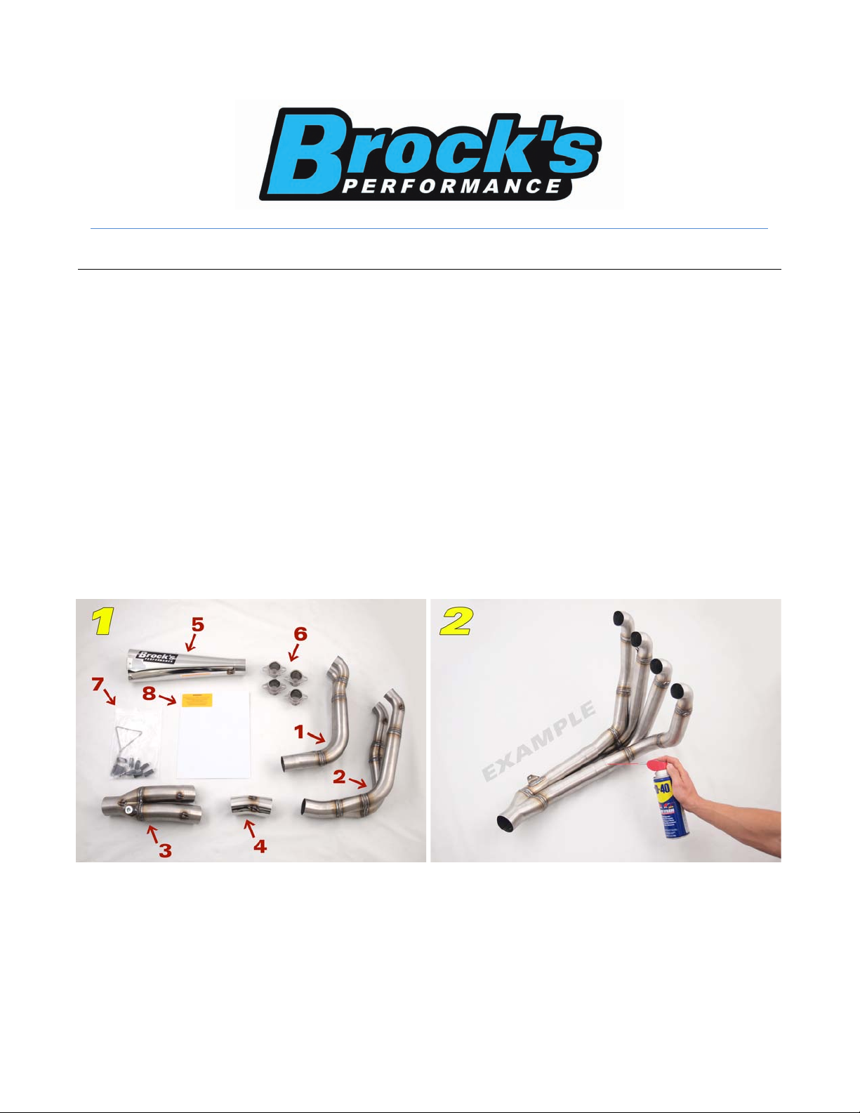
The Package Contents Include (see figure 1):
1. One (1) Left Side Primary (cylinders 1 & 2)
2. One (1) Right Side Primary (cylinders 3 & 4)
3. One (1) Collector
4. One (1) Elbow
5. One (1) Alien Head/ShortMeg Muffler
6. Four (4) Flanges
7. One (1) Package Containing Springs, Spring Puller & PAIR Block Off Cap
8. One (1) Installation Instruction Package
If any parts are missing, contact Brock’s Performance.
Note: A slight ovaling of the tubing can occur during the manufacturing process, this is normal.
A twisting motion may be required during assembly/disassembly.
Step 2: Pre-Assemble Primaries, Collector, and Elbow to Ensure Proper Fit Between
All Parts: The pre-assembled system is shown (see figure 2.) Pre-assembly helps to detect any potential
shipping damage and ensures that all parts fit properly. Apply WD-40® to the pipe joints to ease assembly,
adjustment, and especially disassembly.
Caution: During the following steps, the bodywork should remove with ease. If you
feel resistance, stop and assess the situation before continuing.
Page 2
Document ID 996512
Page 2 of 6
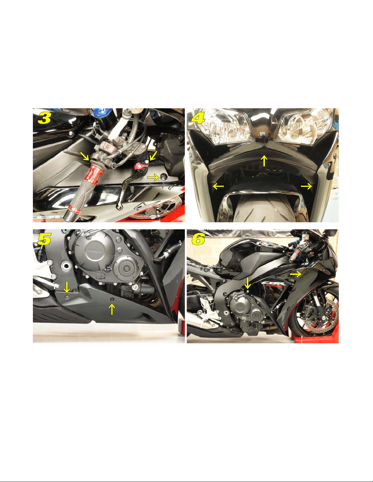
Step 3: Remove Bodywork: Start with removing the air duct cover (outside of air duct tubes), each side
has two (2) Phillips head screws and one (1) hex head screw (see figure 3.) Remove the air intake cover (below
headlamps) with three (3) plastic fasteners/snap rivets (see figure 4.) Remove the lower cowl, two (2) hex head
screws on each side and slide rearward to release clips (see figure 5.) Remove middle cowls, one (1) hex head
screw on each side and one (1) plastic fastener/snap rivet on the inside of each cowl, gently pull each outward,
detaching the tabs from the upper cowl to remove (see figure 6.) Refer to the factory service manual for more
detailed instructions.
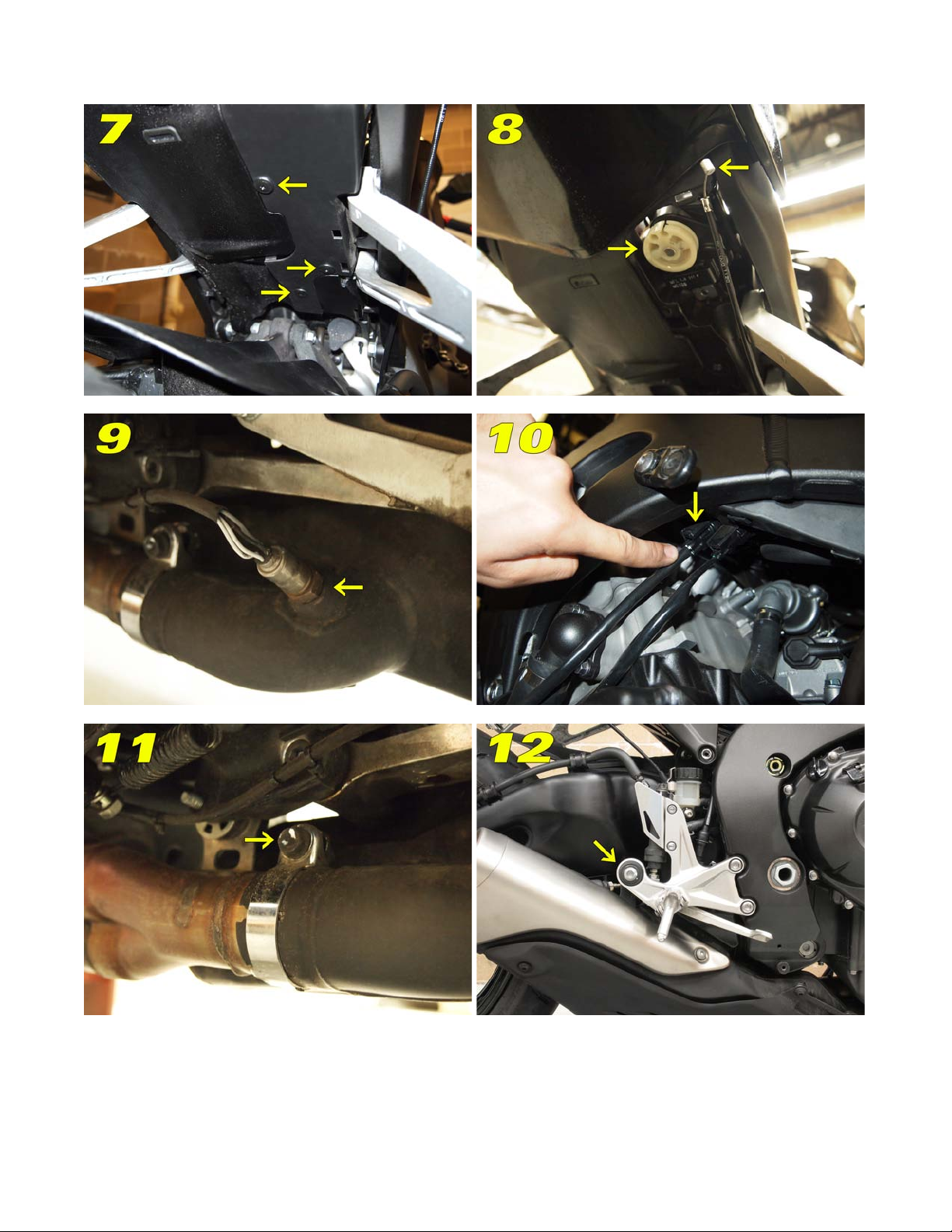
Step 4: Remove Muffler: Remove the exhaust valve cable. Under the tail next to the passenger foot peg,
remove the small cover with three (3) plastic fasteners/snap rivets (see figure 7.) Turn the pulley clockwise and
remove the cable (see figure 8.) Replace the cover. Remove the O2 sensor by unscrewing it from the muffler (see
figure 9) and unplugging it from the connector on the left hand side of the bike, under the frame (see figure 10.)
Loosen the muffler clamp bolt; it only needs loosened, not removed (see figure 11.) While supporting the muffler,
remove the nut and bolt assembly securing the muffler to the muffler-mounting bracket (see figure 12.) Release
the exhaust valve cable from its clips. You can now remove the muffler by gently sliding it rearward while
supporting its weight.
Page 3
Document ID 996512
Page 3 of 6
Page 4
Document ID 996512
Page 4 of 6
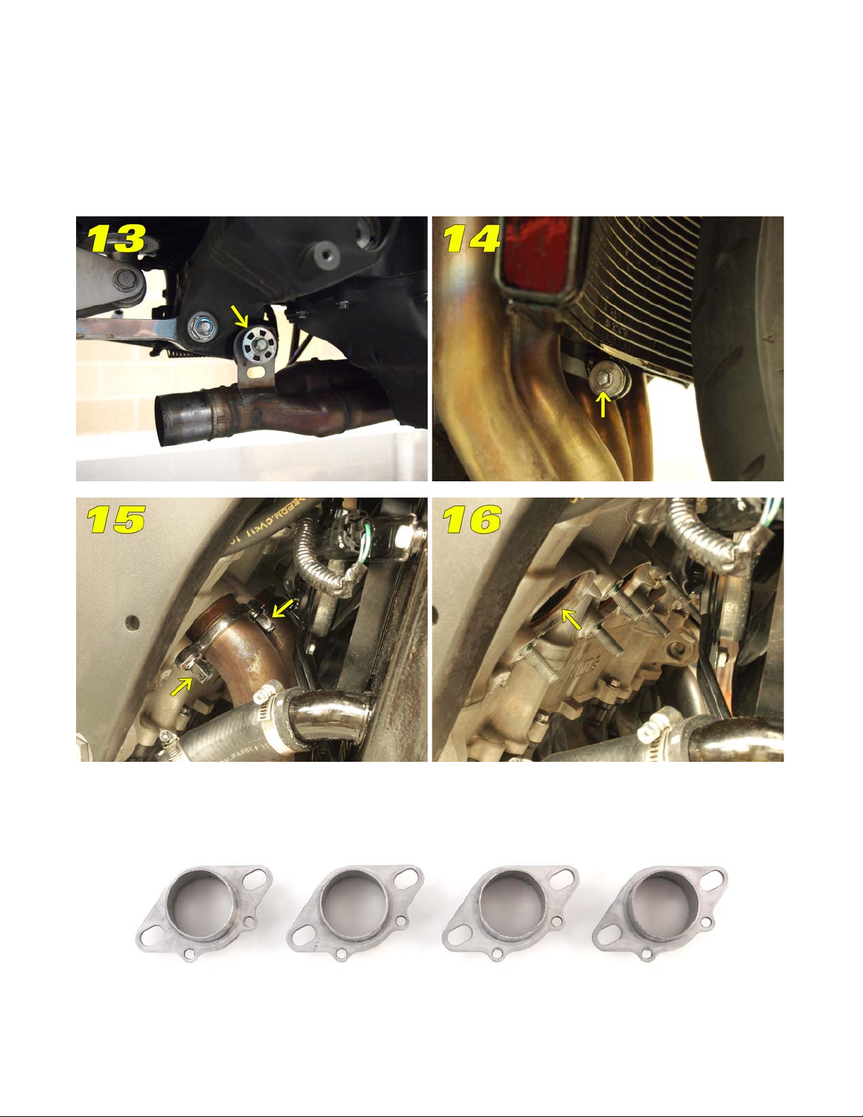
Step 5: Remove Primaries: Remove the one (1) mounting bolt supporting the exhaust at the rear of the
engine (see figure 13.) Remove the one (1) lower mounting bolt from the radiator bracket (see figure 14.) You
can gently push the radiator forward to make room for the removal of the primaries. Remove all eight (8) of the
nuts holding the four primaries to the head (see figure 15) and remove the OEM primaries. Be careful not to hit
the flanges of the pipes on the radiator, some times a piece of cardboard will help in this area for protection of
the radiator. Check to be sure the exhaust gaskets are still in the head; these will be reused (see figure 16.)
Step 6: Install Flanges: Attach the flanges with the larger flared side against the gaskets in the cylinder
head and aligned as shown below. Make sure flanges are flat to the gaskets; do not tighten until the next step.
Page 5
Document ID 996512
Page 5 of 6
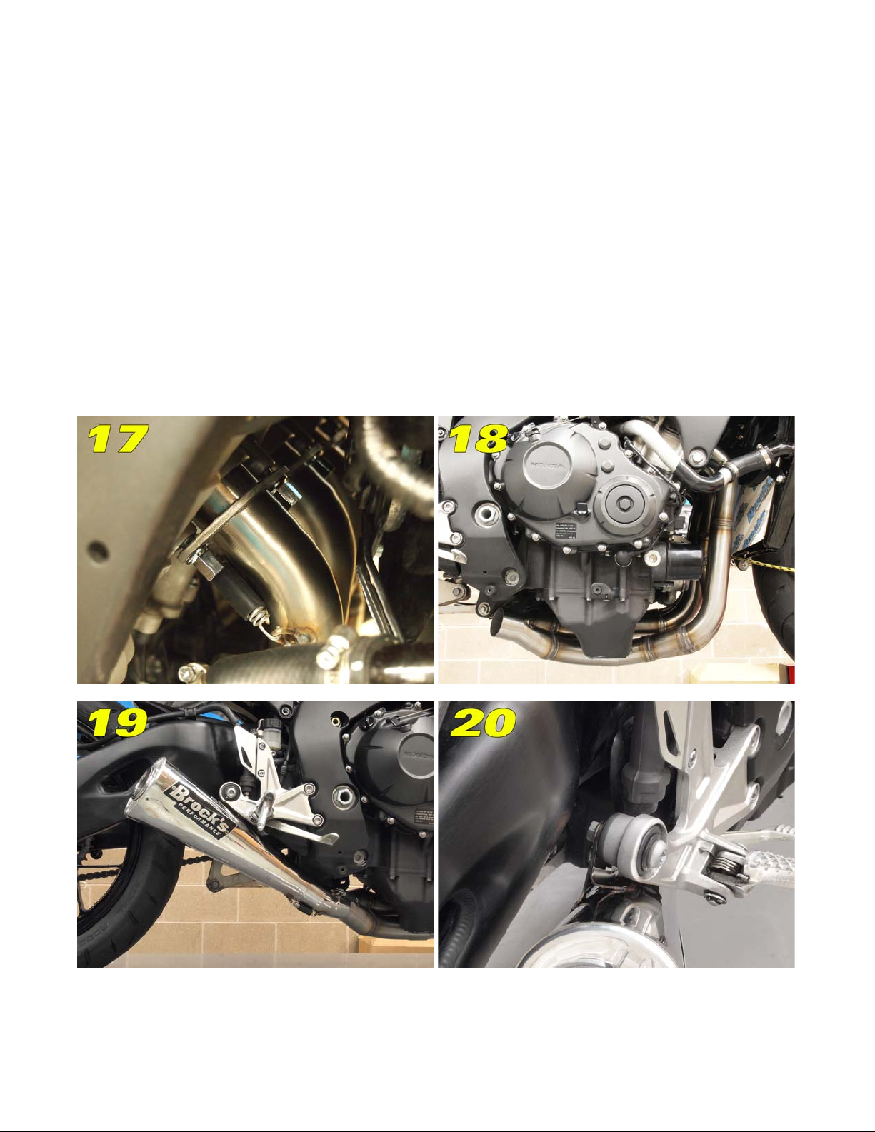
Step 7: Install Primaries (see figure 17): Install the left side primary (cylinders 1 & 2) onto the
flanges, making sure not to hit the radiator. Attach one (1) spring to the tabs on each of the primaries. Repeat
for the right side primary (cylinders 3 & 4.) Tighten the flanges to 10-15 ft-lb. to promote a proper seal. Make
sure the radiator hose, as well as other hoses have clearance from the head pipes.
Step 8: Install Collector (see figure 18): Install the collector onto the primaries, aligning the spring
tabs. Install the two (2) springs. Once the springs are on, move the collector a bit from side to side and up and
down to fully seat the collector and primaries.
Step 9: Install Elbow and Muffler (see figures 19 & 20): Slip the large diameter end of the
elbow onto the collector. Adjust as necessary to ensure that the spring tabs align and install both springs. Install
the muffler onto the elbow. Adjust as necessary to ensure that the mounting bracket lines up with the OEM
mounting location. Insert the OEM muffler-mounting bolt through the OEM location and through the bracket on
the muffler. Place the OEM washer then nut on the bolt and tighten enough to hold the system in place. Do not
fully tighten until final adjustments have been made. Install the springs on the spring tabs and adjust the
assembly by hand as required to ensure proper clearance between the belly pan and muffler.
Page 6
Document ID 996512
Page 6 of 6
Step 10: Clean System of Finger Prints: With any exhaust system you must clean all oil and finger
prints off before starting the motorcycle to ensure there will not be finger prints “burned” into the exhaust.
Carefully use a mild cleaner such as Original Bike Spirits spray polish & cleaner.
Step 11: Re-attach Radiator Bracket: To re-attach the radiator to the lower bracket, insert the screw
removed earlier in the bottom radiator mount and tighten.
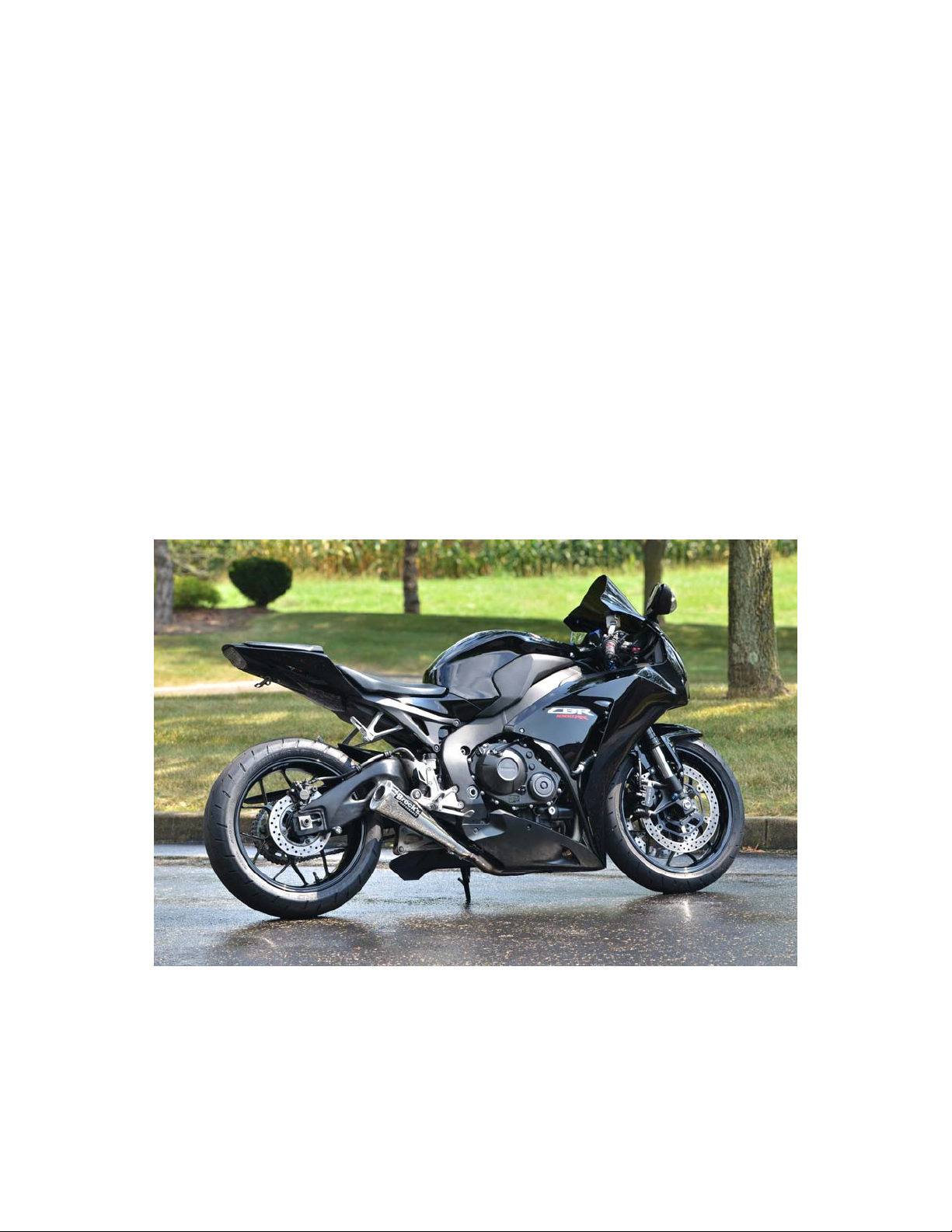
Step 12: Install Bodywork and Check Clearance: Re-install the bodywork in the reverse order
that it was removed and check for clearance between exhaust and bodywork.
Bodywork must be at least ¼
of an inch from any part of the exhaust system.
Brock’s Performance does not warrant burned plastic.
Additional: Perform the air valve block off modifications detailed in the instructions included with your
purchase. Install the appropriate Power Commander & map for your application.
***CAUTION: PAIR BLOCK OFF MUST BE PERFORMED IN ORDER TO
PREVENT PREMATURE EXHAUST FAILURE. PLEASE REFER TO THE PAIR
BLOCK OFF INSTRUCTIONS THAT WERE INCLUDED OR FIND THEM AT
BROCKSPERFORMANCE.COM. FAILURE TO PERFORM THIS
MODIFICATION WILL VOID PRODUCT WARRANTY***
All Brock’s Performance products are designed for closed-course racetrack use ONLY!
For more information on Brock’s Performance Warranty and Terms and Conditions:
www.BrocksPerformance.com
> About Us > Terms and Conditions
For Questions and Comments:
www.BrocksPerformance.com > Customer Service > Contact Us
or call the Tech Line 937-912-0054
 Loading...