

Page 1

HARDWARE INSTALLATION GUIDE
Brocade X6-8 Director
Hardware Installation Guide
53-1004105-07
12 May 2017
Page 2

©
2017, Brocade Communications Systems, Inc. All Rights Reserved.
Brocade, the B-wing symbol, and MyBrocade are registered trademarks of Brocade Communications Systems, Inc., in the United States and in other
countries. Other brands, product names, or service names mentioned of Brocade Communications Systems, Inc. are listed at www.brocade.com/en/legal/
brocade-Legal-intellectual-property/brocade-legal-trademarks.html. Other marks may belong to third parties.
Notice: This document is for informational purposes only and does not set forth any warranty, expressed or implied, concerning any equipment,
equipment feature, or service oered or to be oered by Brocade. Brocade reserves the right to make changes to this document at any time, without
notice, and assumes no responsibility for its use. This informational document describes features that may not be currently available. Contact a Brocade
sales oce for information on feature and product availability. Export of technical data contained in this document may require an export license from the
United States government.
The authors and Brocade Communications Systems, Inc. assume no liability or responsibility to any person or entity with respect to the accuracy of this
document or any loss, cost, liability, or damages arising from the information contained herein or the computer programs that accompany it.
The product described by this document may contain open source software covered by the GNU General Public License or other open source license
agreements. To nd out which open source software is included in Brocade products, view the licensing terms applicable to the open source software, and
obtain a copy of the programming source code, please visit http://www.brocade.com/support/oscd.
2 53-1004105-07
Brocade X6-8 Director Hardware Installation Guide
Page 3

Contents
Preface...................................................................................................................................................................................................................................9
Document conventions............................................................................................................................................................................................................................9
Notes, cautions, and warnings.....................................................................................................................................................................................................9
Text formatting conventions.........................................................................................................................................................................................................9
Command syntax conventions.................................................................................................................................................................................................10
Brocade resources..................................................................................................................................................................................................................................10
Document feedback.............................................................................................................................................................................................................................. 10
Contacting Brocade Technical Support......................................................................................................................................................................................... 11
Brocade customers.......................................................................................................................................................................................................................11
Brocade OEM customers..........................................................................................................................................................................................................11
About This Document..................................................................................................................................................................................................... 13
Supported hardware and software...................................................................................................................................................................................................13
What is new in this document............................................................................................................................................................................................................14
Device Overview...............................................................................................................................................................................................................15
Product features.......................................................................................................................................................................................................................................15
Hardware components..........................................................................................................................................................................................................................15
Port-side view of device.......................................................................................................................................................................................................................16
Port-side slot numbering.....................................................................................................................................................................................................................18
Nonport-side view of the device .....................................................................................................................................................................................................18
Preparing for the Installation..........................................................................................................................................................................................21
Safety precautions..................................................................................................................................................................................................................................21
General precautions......................................................................................................................................................................................................................21
ESD precautions............................................................................................................................................................................................................................ 22
Power precautions.........................................................................................................................................................................................................................22
Lifting precautions.........................................................................................................................................................................................................................22
Laser precautions.......................................................................................................................................................................................................................... 23
Facility requirements..............................................................................................................................................................................................................................23
Time and items required for installation.........................................................................................................................................................................................24
Quick installation checklists................................................................................................................................................................................................................25
Pre-installation tasks....................................................................................................................................................................................................................25
Installation and initial conguration.........................................................................................................................................................................................25
Items shipped...........................................................................................................................................................................................................................................26
Mounting the Device........................................................................................................................................................................................................29
Mounting options....................................................................................................................................................................................................................................29
Mounting precautions............................................................................................................................................................................................................................29
Unpacking and transporting the device.........................................................................................................................................................................................30
Installing the 14U Rack Mount Kit for Four-Post Racks (XBR-DCX-0120 and XBR-DCX-0152) ..................................................................31
Time and items required.............................................................................................................................................................................................................31
Parts list............................................................................................................................................................................................................................................. 32
Parts list – NEBS kit..................................................................................................................................................................................................................... 33
Assembling the rack hardware.................................................................................................................................................................................................34
Installing the device in the rack................................................................................................................................................................................................ 37
Installing the 14U Chassis Mid-Mount Rack Kit for Two-Post Racks (XBR-DCX-0121)...................................................................................... 39
Time and Items required.............................................................................................................................................................................................................40
Brocade X6-8 Director Hardware Installation Guide
53-1004105-07 3
Page 4

Parts list............................................................................................................................................................................................................................................. 40
Assembling the rack hardware.................................................................................................................................................................................................41
Installing the device in the rack................................................................................................................................................................................................ 43
Removing logo bezel protective cover...........................................................................................................................................................................................45
Initial Setup and Verication.......................................................................................................................................................................................... 47
Conguration and verication task guide......................................................................................................................................................................................47
Items required...........................................................................................................................................................................................................................................48
Providing power to the device........................................................................................................................................................................................................... 48
Connecting power cord to AC power supplies..................................................................................................................................................................49
Connecting power cord to HVAC/HVDC power supplies............................................................................................................................................50
Establishing a serial connection to the device.............................................................................................................................................................................55
Conguring the IP addresses.............................................................................................................................................................................................................56
Establishing an Ethernet connection to the device...................................................................................................................................................................58
Setting the domain ID........................................................................................................................................................................................................................... 59
Setting the date and time.....................................................................................................................................................................................................................59
Setting the time zone................................................................................................................................................................................................................... 60
Synchronizing local time with an external source.............................................................................................................................................................62
Customizing the chassis and switch name.................................................................................................................................................................................. 62
Verifying installed licenses and license key..................................................................................................................................................................................63
Verifying correct operation..................................................................................................................................................................................................................63
Backing up the conguration.............................................................................................................................................................................................................64
Powering down the chassis.................................................................................................................................................................................................................65
Installing Transceivers and Cables................................................................................................................................................................................69
Supported transceivers and cables................................................................................................................................................................................................. 69
Port and extension blade transceivers .................................................................................................................................................................................70
Core routing blades.......................................................................................................................................................................................................................71
Time and items required...................................................................................................................................................................................................................... 74
Precautions specic to transceivers and cables.........................................................................................................................................................................74
Cleaning the ber-optic connectors................................................................................................................................................................................................75
Cable management................................................................................................................................................................................................................................75
Installing an SFP+ transceiver............................................................................................................................................................................................................76
Replacing an SFP+ transceiver..........................................................................................................................................................................................................78
Installing a QSFP transceiver.............................................................................................................................................................................................................80
Replacing a QSFP transceiver...........................................................................................................................................................................................................81
Verifying the operation of new transceivers.................................................................................................................................................................................83
Monitoring the Device..................................................................................................................................................................................................... 85
Introduction................................................................................................................................................................................................................................................85
Interpreting port blade LEDs..............................................................................................................................................................................................................85
Interpreting extension blade LEDs...................................................................................................................................................................................................87
Interpreting control processor blade LEDs...................................................................................................................................................................................90
Interpreting core routing blade LEDs..............................................................................................................................................................................................91
Interpreting WWN card LEDs............................................................................................................................................................................................................93
Interpreting power supply LEDs.......................................................................................................................................................................................................94
Interpreting fan assembly LEDs....................................................................................................................................................................................................... 96
Interpreting POST and boot results.................................................................................................................................................................................................98
POST..................................................................................................................................................................................................................................................98
Boot.....................................................................................................................................................................................................................................................99
Using monitoring commands............................................................................................................................................................................................................99
chassisShow.................................................................................................................................................................................................................................... 99
4 53-1004105-07
Brocade X6-8 Director Hardware Installation Guide
Page 5

errDump and errShow..............................................................................................................................................................................................................103
fanShow..........................................................................................................................................................................................................................................104
haShow........................................................................................................................................................................................................................................... 104
historyShow...................................................................................................................................................................................................................................104
psShow........................................................................................................................................................................................................................................... 106
sensorShow...................................................................................................................................................................................................................................106
slotShow.........................................................................................................................................................................................................................................107
sfpShow..........................................................................................................................................................................................................................................107
switchShow....................................................................................................................................................................................................................................114
supportSave..................................................................................................................................................................................................................................115
tempShow......................................................................................................................................................................................................................................117
Running diagnostic tests...................................................................................................................................................................................................................118
Port and Extension Blades.......................................................................................................................................................................................... 119
Port blade overview.............................................................................................................................................................................................................................119
FC32-48 blade port numbering and trunking.............................................................................................................................................................. 119
Extension blade overview.................................................................................................................................................................................................................121
Extension features......................................................................................................................................................................................................................121
SX6 blade port numbering and trunking.......................................................................................................................................................................... 122
Precautions specic to the blade...................................................................................................................................................................................................124
Faulty blade indicators.......................................................................................................................................................................................................................124
Time and items required for removal and installation...........................................................................................................................................................125
Removing a blade................................................................................................................................................................................................................................125
Installing a blade...................................................................................................................................................................................................................................127
Verifying blade operation..................................................................................................................................................................................................................128
Core Routing Blades..................................................................................................................................................................................................... 131
Core routing blade overview............................................................................................................................................................................................................131
CR32-8 port numbering.........................................................................................................................................................................................................131
ICL trunking groups...................................................................................................................................................................................................................133
ICL cabling congurations......................................................................................................................................................................................................134
Precautions specic to the blade...................................................................................................................................................................................................135
Faulty core routing blade indicators..............................................................................................................................................................................................136
Time and items required................................................................................................................................................................................................................... 137
Replacing a core routing blade.......................................................................................................................................................................................................137
Preparing for replacement...................................................................................................................................................................................................... 137
Removing a core routing blade.............................................................................................................................................................................................138
Installing a core routing blade................................................................................................................................................................................................139
Verifying blade operation..................................................................................................................................................................................................................141
Control Processor Blades............................................................................................................................................................................................ 143
Control processor blade overview.................................................................................................................................................................................................143
CPX6 port identication...........................................................................................................................................................................................................144
Precautions specic to the blade...................................................................................................................................................................................................144
Blade fault indicators..........................................................................................................................................................................................................................145
Blade replacement task guide........................................................................................................................................................................................................146
Replacing CP blade (hot-swap)............................................................................................................................................................................................ 146
Replacing a CP blade (cold-swap).......................................................................................................................................................................................146
Time and items required for replacement..................................................................................................................................................................................147
Preparing for replacement................................................................................................................................................................................................................147
Replacing a CP blade.........................................................................................................................................................................................................................148
Hot-swap procedure..................................................................................................................................................................................................................148
Brocade X6-8 Director Hardware Installation Guide
53-1004105-07 5
Page 6

Cold-swap procedure................................................................................................................................................................................................................154
Completing the replacement..................................................................................................................................................................................................158
Verifying blade operation..................................................................................................................................................................................................................158
WWN Cards.....................................................................................................................................................................................................................161
WWN card overview...........................................................................................................................................................................................................................161
WWN card location and numbering....................................................................................................................................................................................161
Precautions specic to WWN cards.............................................................................................................................................................................................162
WWN card fault indicators................................................................................................................................................................................................................163
WWN card replacement task guide..............................................................................................................................................................................................164
Replacing WWN cards (hot-swap).......................................................................................................................................................................................164
Replacing WWN cards (cold-swap).....................................................................................................................................................................................164
Time and items required for replacement..................................................................................................................................................................................164
Using the wwnrecover utility............................................................................................................................................................................................................165
Preparing for WWN card replacement........................................................................................................................................................................................165
Hot-swap replacement...................................................................................................................................................................................................................... 167
Cold-swap replacement.................................................................................................................................................................................................................... 168
Removing the WWN card and bezel............................................................................................................................................................................................170
Conguring airow direction on WWN cards........................................................................................................................................................................... 171
Verifying WWN card operation.......................................................................................................................................................................................................172
Power Supply Assemblies............................................................................................................................................................................................173
AC power supply overview...............................................................................................................................................................................................................173
HVAC/HVDC power supply overview........................................................................................................................................................................................174
Power supply assembly numbering.............................................................................................................................................................................................176
Fan and power supply airow......................................................................................................................................................................................................... 176
Precautions specic to power supply assembly.....................................................................................................................................................................178
Power supply assembly fault indicators.....................................................................................................................................................................................178
Power supply assembly task guide..............................................................................................................................................................................................179
Installing additional power supply (hot-install)................................................................................................................................................................179
Replacing power supply assembly (hot-swap)...............................................................................................................................................................179
Replace or install power supply assembly (cold-install or cold-swap).................................................................................................................179
Time and items required................................................................................................................................................................................................................... 180
Removing a power supply................................................................................................................................................................................................................180
Installing a power supply...................................................................................................................................................................................................................181
Verifying power supply operation..................................................................................................................................................................................................182
Fan Assemblies.............................................................................................................................................................................................................. 185
Fan assembly overview.....................................................................................................................................................................................................................185
Fan and power supply airow................................................................................................................................................................................................186
Fan assembly numbering........................................................................................................................................................................................................188
Precautions specic to fan assemblies.......................................................................................................................................................................................189
Fan assembly fault indicators..........................................................................................................................................................................................................189
Fan assembly task guide..................................................................................................................................................................................................................189
Replacing fan assembly (hot-swap)....................................................................................................................................................................................190
Replacing fan assembly (cold-swap)..................................................................................................................................................................................190
Time and items required................................................................................................................................................................................................................... 190
Removing a fan assembly ...............................................................................................................................................................................................................190
Installing a fan assembly...................................................................................................................................................................................................................192
Verifying fan operation.......................................................................................................................................................................................................................192
Blade Filler Panels.........................................................................................................................................................................................................193
6 53-1004105-07
Brocade X6-8 Director Hardware Installation Guide
Page 7

Blade ller panel removal and replacement..............................................................................................................................................................................193
Removing a ller panel...................................................................................................................................................................................................................... 193
Installing a ller panel......................................................................................................................................................................................................................... 194
Cable management comb............................................................................................................................................................................................197
Cable management comb overview............................................................................................................................................................................................197
Time and items required for removal and installation...........................................................................................................................................................197
Removing cable management comb..........................................................................................................................................................................................197
Installing cable management comb.............................................................................................................................................................................................198
Chassis door................................................................................................................................................................................................................... 199
Chassis door overview.......................................................................................................................................................................................................................199
Time and items required................................................................................................................................................................................................................... 199
Removing a chassis door.................................................................................................................................................................................................................199
Installing a chassis door.................................................................................................................................................................................................................... 200
Replacing the Chassis...................................................................................................................................................................................................203
Chassis replacement overview.......................................................................................................................................................................................................203
Precautions specic to chassis replacement............................................................................................................................................................................203
Chassis replacement task guide....................................................................................................................................................................................................204
Chassis fault indicators......................................................................................................................................................................................................................204
Time and items required................................................................................................................................................................................................................... 205
Preparing for replacement................................................................................................................................................................................................................205
Recording critical device and SAN information..............................................................................................................................................................206
Disconnecting from network and fabric............................................................................................................................................................................209
Removing components from the chassis..................................................................................................................................................................................209
Installing the replacement chassis.................................................................................................................................................................................................210
Installing components into the chassis.......................................................................................................................................................................................210
Synchronizing airow direction on WWN cards......................................................................................................................................................................211
Downloading the conguration......................................................................................................................................................................................................212
Reconnecting system to the network and fabric.....................................................................................................................................................................212
Verifying correct operation of system..........................................................................................................................................................................................213
Verifying correct conguration of the fabric..............................................................................................................................................................................215
Brocade X6 Directors Technical Specications...................................................................................................................................................... 217
System specications.........................................................................................................................................................................................................................217
Fibre channel..........................................................................................................................................................................................................................................219
LEDs..........................................................................................................................................................................................................................................................219
Other......................................................................................................................................................................................................................................................... 220
Weight and physical dimensions................................................................................................................................................................................................... 220
Environmental requirements........................................................................................................................................................................................................... 221
Power supply specications (per PSU).......................................................................................................................................................................................221
Power supply requirements.............................................................................................................................................................................................................222
Power consumption for AC power supplies (typical conguration).................................................................................................................................223
Power consumption for AC power supplies (idle conguration).......................................................................................................................................223
Power consumption for AC power supplies (maximum conguration).........................................................................................................................224
Power consumption for HVAC/HVDC power supplies (typical conguration).......................................................................................................... 224
Power consumption for HVAC/HVDC power supplies (idle conguration)................................................................................................................ 225
Power consumption for HVAC/HVDC power supplies (maximum conguration)...................................................................................................225
Power consumption (modules).......................................................................................................................................................................................................226
Fibre Channel data transmission ranges....................................................................................................................................................................................227
Data port specications (Fibre Channel).....................................................................................................................................................................................227
Brocade X6-8 Director Hardware Installation Guide
53-1004105-07 7
Page 8

Class 1M transceiver specication...............................................................................................................................................................................................228
Serial port specications (pinout RJ-45)....................................................................................................................................................................................228
Serial port specications (protocol)...............................................................................................................................................................................................228
Memory specications (per CP blade)........................................................................................................................................................................................228
Regulatory compliance (EMC)........................................................................................................................................................................................................229
Regulatory compliance (safety)...................................................................................................................................................................................................... 229
Regulatory compliance (environmental)..................................................................................................................................................................................... 229
Regulatory Statements.................................................................................................................................................................................................231
BSMI statement (Taiwan)..................................................................................................................................................................................................................231
Canadian requirements......................................................................................................................................................................................................................231
CE statement.........................................................................................................................................................................................................................................231
China ROHS.......................................................................................................................................................................................................................................... 232
FCC warning (US only)...................................................................................................................................................................................................................... 232
KCC statement (Republic of Korea)..............................................................................................................................................................................................232
VCCI statement.....................................................................................................................................................................................................................................232
Germany statement.............................................................................................................................................................................................................................232
Cautions and Danger Notices..................................................................................................................................................................................... 233
Cautions...................................................................................................................................................................................................................................................233
General cautions......................................................................................................................................................................................................................... 233
Electrical cautions.......................................................................................................................................................................................................................235
Cautions related to equipment weight...............................................................................................................................................................................237
Danger Notices.....................................................................................................................................................................................................................................238
General dangers..........................................................................................................................................................................................................................238
Dangers related to equipment weight................................................................................................................................................................................238
Electrical dangers........................................................................................................................................................................................................................239
Laser dangers.............................................................................................................................................................................................................................. 241
8 53-1004105-07
Brocade X6-8 Director Hardware Installation Guide
Page 9

Preface
• Document conventions......................................................................................................................................................................................9
• Brocade resources............................................................................................................................................................................................ 10
• Document feedback.........................................................................................................................................................................................10
• Contacting Brocade Technical Support....................................................................................................................................................11
Document conventions
The document conventions describe text formatting conventions, command syntax conventions, and important notice formats used in
Brocade technical documentation.
Notes, cautions, and warnings
Notes, cautions, and warning statements may be used in this document. They are listed in the order of increasing severity of potential
hazards.
NOTE
A Note provides a tip, guidance, or advice, emphasizes important information, or provides a reference to related information.
ATTENTION
An Attention statement indicates a stronger note, for example, to alert you when trac might be interrupted or the device might
reboot.
CAUTION
A Caution statement alerts you to situations that can be potentially hazardous to you or cause damage to hardware,
rmware, software, or data.
DANGER
A Danger statement indicates conditions or situations that can be potentially lethal or extremely hazardous to you. Safety
labels are also attached directly to products to warn of these conditions or situations.
Text formatting conventions
Text formatting conventions such as boldface, italic, or Courier font may be used to highlight specic words or phrases.
Format Description
bold text Identies command names.
Identies keywords and operands.
Identies the names of GUI elements.
Identies text to enter in the GUI.
italic text Identies emphasis.
Identies variables.
Identies document titles.
Courier font
Identies CLI output.
Brocade X6-8 Director Hardware Installation Guide
53-1004105-07 9
Page 10

Brocade resources
Format Description
Identies command syntax examples.
Command syntax conventions
Bold and italic text identify command syntax components. Delimiters and operators
relationships.
Convention Description
bold text Identies command names, keywords, and command options.
italic text Identies a variable.
value In Fibre Channel products, a xed value provided as input to a command option is printed in plain text, for
example, --show WWN.
[ ] Syntax components displayed within square brackets are optional.
Default responses to system prompts are enclosed in square brackets.
{ x | y | z } A choice of required parameters is enclosed in curly brackets separated by vertical bars. You must select
one of the options.
In Fibre Channel products, square brackets may be used instead for this purpose.
x | y A vertical bar separates mutually exclusive elements.
< > Nonprinting characters, for example, passwords, are enclosed in angle brackets.
... Repeat the previous element, for example, member[member...].
\ Indicates a “soft” line break in command examples. If a backslash separates two lines of a command
input, enter the entire command at the prompt without the backslash.
dene groupings of parameters and their logical
Brocade resources
Visit the Brocade website to locate related documentation for your product and additional Brocade resources.
White papers, data sheets, and the most recent versions of Brocade software and hardware manuals are available at www.brocade.com.
Product documentation for all supported releases is available to registered users at MyBrocade.
Click the Support tab and select Document Library to access product documentation on MyBrocade or www.brocade.com. You can
locate documentation by product or by operating system.
Release notes are bundled with software downloads on MyBrocade. Links to software downloads are available on the MyBrocade landing
page and in the Document Library.
Document feedback
Quality is our
However, if you nd an error or an omission, or you think that a topic needs further development, we want to hear from you. You can
provide feedback in two ways:
• Through the online feedback form in the HTML documents posted on www.brocade.com
• By sending your feedback to documentation@brocade.com
Provide the publication title, part number, and as much detail as possible, including the topic heading and page number if applicable, as
well as your suggestions for improvement.
10 53-1004105-07
rst concern at Brocade, and we have made every eort to ensure the accuracy and completeness of this document.
Brocade X6-8 Director Hardware Installation Guide
Page 11

Contacting Brocade Technical Support
Contacting Brocade Technical Support
As a Brocade customer, you can contact Brocade Technical Support 24x7 online or by telephone. Brocade OEM customers should
contact their OEM/solution provider.
Brocade customers
For product support information and the latest information on contacting the Technical Assistance Center, go to www.brocade.com and
select Support.
If you have purchased Brocade product support directly from Brocade, use one of the following methods to contact the Brocade
Technical Assistance Center 24x7.
Online Telephone
Preferred method of contact for non-urgent issues:
• Case management through the MyBrocade portal.
• Quick Access links to Knowledge Base, Community, Document
Library, Software Downloads and Licensing tools
Required for Sev 1-Critical and Sev 2-High issues:
• Continental US: 1-800-752-8061
• Europe, Middle East, Africa, and Asia Pacic: +800-AT FIBREE
(+800 28 34 27 33)
• Toll-free numbers are available in many countries.
• For areas unable to access a toll-free number:
+1-408-333-6061
Brocade OEM customers
If you have purchased Brocade product support from a Brocade OEM/solution provider, contact your OEM/solution provider for all of
your product support needs.
• OEM/solution providers are trained and
• Brocade provides backline support for issues that cannot be resolved by the OEM/solution provider.
• Brocade Supplemental Support augments your existing OEM support contract, providing direct access to Brocade expertise.
For more information, contact Brocade or your OEM.
• For questions regarding service levels and response times, contact your OEM/solution provider.
certied by Brocade to support Brocade® products.
Brocade X6-8 Director Hardware Installation Guide
53-1004105-07 11
Page 12

12 53-1004105-07
Brocade X6-8 Director Hardware Installation Guide
Page 13

About This Document
• Supported hardware and software..............................................................................................................................................................13
• What is new in this document.......................................................................................................................................................................14
Supported hardware and software
The following tables list the major eld replaceable units (FRUs) and rack mount kits supported for the Brocade X6 Director. First release
of this product was at Fabric OS 8.0.1.
TABLE 1 OS-dependent FRUs
FRU Part Number Short Description Introduced (OS) Currently
supported
AC power supply XBR-X6-
RACNPIPSU-0104
XBR-X6RACNPEPSU-010
4
HVAC/HVDC power
supply
Fan assembly XBR-X6-NPI-0122 Supports NPI airow Fabric OS 8.0.1 Yes
FC32-48 blade XBR-X6-0148 Fibre Channel port blade with 48 32- Gbps SFP+
CPX6 blade XBR-CPX6-0103 Control processor (CP) blade Fabric OS 8.0.1 Yes
CR32-8 blade XBR-X68-0106 Core routing (CR) blade with 16 4x32 -Gbps
SX6 blade XBR-SX6-0000 Extension (X) blade with 16 32-Gbps Fibre
WWN card XBR-X6-0124 World Wide Name card Fabric OS 8.0.1 Yes
XBR-X6HVNPIPSU-0104
XBR-X6HVNPEPSU-0104
XBR-X6NPE-0122
Provides 1450 W (100-120 VAC) and 2870 W
(200-240 VAC). This model supports nonportside intake (NPI) airow.
Provides 1450 W (100-120 VAC) and 2870 W
(200-277 VAC). This model supports nonportside exhaust (NPE) airow.
Dual-function high-voltage model provides the
following power output from either high-voltage
AC or DC power source:
• 1450 W (100-120 VAC)
• 2870 W (200-277 VAC)
• 2870 W (240-380 VDC)
This model supports nonport-side intake (NPI)
airow.
Dual-function high-voltage model provides the
following power output from either high-voltage
AC or DC power source:
• 1450 W (100-120 VAC)
• 2870 W (200-277 VAC)
• 2870 W (240-380 VDC)
This model supports nonport-side exhaust (NPE)
airow.
Supports NPE airow Fabric OS 8.0.1 Yes
ports
QSFP+ ports for Brocade X6-8 Director.
Channel SFP+ ports, 16 10-GbE SFP+ ports,
and 2 40-GbE QSFP+ ports
Fabric OS 8.0.1 Yes
Fabric OS 8.0.1 Yes
Fabric OS 8.1.0a Yes
Fabric OS 8.1.0a Yes
Fabric OS 8.0.1 Yes
Fabric OS 8.0.1 Yes
Fabric OS 8.0.1 Yes
Brocade X6-8 Director Hardware Installation Guide
53-1004105-07 13
Page 14

What is new in this document
TABLE 1 OS-dependent FRUs (continued)
FRU Part Number Short Description Introduced (OS) Currently
supported
Blade slot ller panel XBR-X6-0128 Required to cover empty slot to maintain airow in
chassis.
Power supply assembly
slot ller panel
XBR-X6-0130 Required to cover empty slot to maintain airow in
chassis.
Fabric OS 8.0.1 Yes
Fabric OS 8.0.1 Yes
TABLE 2 Rack mount kits
Kit Part Number Short Description
Rack mount kits XBR-DCX-0121 Mid-mount rack mount kit for two-post rack
XBR-DCX-0120 14U rack mount kit for four-post rack (27–31 in.)
XBR-DCX-0152 14U rack mount kit for four-post rack (22 in.)
What is new in this document
The following changes have been made in this document:
• Removed "Verifying the PID mode" section from "Initial setup and conguration" section because it is no longer a conguration
requirement.
• Modied the following sections in Replacing the Chassis on page 203:
– Recording critical device and SAN information on page 206 – Revised introduction to using critical information checklist,
removed note to run supportShow command, removed -sw option from step to enter ipAddrShow command, and added
more information to step to enter supportShow command.
– Reconnecting system to the network and fabric on page 212 – Revised step 1 to include references to sections in "Initial
conguration" for connecting serial cable, establishing a serial connection, conguring IP addresses, and establishing an
Ethernet connection to the device.
– Verifying correct operation of system on page 213 – Moved this section to after Reconnecting system to the network and
fabric on page 212.
– Verifying correct conguration of the fabric on page 215 – Added step to modify SCC policy for fabric, if one exists, to add
WWN of new chassis.
• In Brocade X6 Directors Technical Specications on page 217, modied the “Fibre Channel data transmission ranges” table.
For 32 Gbps transmission, under 50nm, the OM2 range was doubled to 20m, and the extra OM4 entry was removed. Under
9nm, the 10m value was replaced with “N/A”.
14 53-1004105-07
Brocade X6-8 Director Hardware Installation Guide
Page 15

Device Overview
• Product features.................................................................................................................................................................................................15
• Hardware components....................................................................................................................................................................................15
• Port-side view of device.................................................................................................................................................................................16
• Port-side slot numbering............................................................................................................................................................................... 18
• Nonport-side view of the device ................................................................................................................................................................18
Product features
Key product features for this device include the following:
• Redundant and hot-swappable SFP, SFP+, SFP28, and QSFP+ transceivers; port, extension, control processor (CP) and core
routing (CR) blades; power supply assemblies, fan assemblies, and WWN cards that enable a high availability platform and allow
nondisruptive software upgrades for mission-critical SAN applications.
• Up to 384 32-Gbps external ports and 32 4x32-Gbps QSFP (ICL) ports in a single chassis, enabling high density SAN
congurations with reduced footprint.
• Support for 48 4-, 8-, 16-, and 32-Gbps autosensing Fibre Channel ports on FC32-48 port blades. Trunking technology
groups up to eight ports to create high performance 256-Gbps ISL trunks between switches using 32-Gbps ports.
• 10-Gbps FC-type SFPs on FC32-48 port blades and 10-GbE SFPs on the SX6 application blades. The two types of SFPs
are not interchangeable. The 10-Gbps transceivers can be used for any port on the FC32-48 port blades.
• Support for 16 Fibre Channel ports supporting 4-, 8-, 16-, and 32-Gbps; 16 GbE ports supporting 1 or 10 Gbps; and two
GbE ports supporting 40 Gbps on SX6 extension blades. Trunking technology groups up to eight ports to create high
performance 256-Gbps ISL trunks between switches using 32-Gbps ports.
• Support for FC quad SFP (QSFP) ports supporting 4x16 Gbps and 4x32 Gbps on core CR blades. Up to nine chassis in a fullmesh topology and 12 chassis in a core-to-edge topology can be connected using these Fibre Channel ports for inter-chassis
links (ICLs).
• Universal ports that self-congure as E_Ports, F_Ports, EX_Ports, M_Ports (mirror ports), and FICON ports. The 10-Gbps
ports on the port blade can function as E_Ports only.
• ClearLink Diagnostic port (D_Port) functionality on Fibre Channel ports.
• Data compression capabilities through the port blades when ports are congured as ISLs.
• The SX6 blades perform as extension platforms to support Fibre Channel (FC) and FICON data ows and IP-based storage
data ows over an IP WAN.
Hardware components
The device has a modular and scalable mechanical construction that allows a wide range of
maintenance. The device can be mounted with the cables facing either the front or the rear of the equipment rack, and consists of the
following:
• Up to eight slots for hot-swappable port blade assemblies, providing up to 384 32-Gbps Fibre Channel ports.
• Two half-size slots for control processor (CP) blades:
– A single active CP blade can control all the ports in the device.
– The standby CP blade assumes control of the device if the active CP blade fails.
Brocade X6-8 Director Hardware Installation Guide
53-1004105-07 15
exibility in installation, fabric design, and
Page 16

Port-side view of device
• Two slots for core routing (CR) blades:
– CR blade interconnects all port blades.
– Up to 32 4x32-Gbps QSFP (ICL) ports.
– ICL ports allow interconnection with neighboring Director chassis
– Both CR blades are active and can be hot-swapped.
• Up to four slots for modular, hot-swappable 34-port SX6 extension blades. Blades provide 16 32– Gbps Fibre Channel (FC)
ports supporting 8, 16, and 32 Gbps or 16 16-Gbps FC ports supporting 4, 8, and 16 Gbps; 16 GbE ports supporting 1 or
10 Gbps; and 2 GbE ports supporting 40 Gbps. Extension blades enable long-distance communication over an existing IP
infrastructure.
• Modular, hot-swappable eld-replaceable units (FRUs):
– Three fan assemblies, available with nonport-side intake (NPI) or nonport-side exhaust (NPE) airow.
– Up to four power supply assemblies, available with nonport-side intake (NPI) or nonport-side exhaust (NPE) airow.
› Refer to the "Power supply specications (per PSU)" in the Brocade X6 Directors Technical Specications on page
217 for maximum output power, input voltage, input line frequency, and other specications for your power supply
model.
› Refer to the "Power supply requirements" section in the Brocade X6 Directors Technical Specications on page 217
for the minimum number of power supplies required for operation and redundancy when dierent input voltages are
applied, such as low line and high line AC.
› Refer to "Power Consumption" sections in the Brocade X6 Directors Technical Specications on page 217 for power
output data and minimum number of power supplies for supported input voltages.
› Redundant primary power connections ensure high availability. Each power supply assembly has its own connector, so
the number of primary power connections is four for optimum eciency and redundancy.
– Two World Wide Name (WWN) cards located on the nonport side of the device behind the WWN card bezel.
– Blades use small form-factor pluggable (SFP+ and QSFP+) optical transceivers.
› The 10-Gbps speed must be manually set and requires special 10-Gbps FC SFP+ transceivers.
› The 32-Gbps SFP+ transceivers support speeds of 8, 16, and 32 Gbps.
› The 16-Gbps SFP+ transceivers support speeds of 4, 8, and 16 Gbps.
› The 4x32-Gbps QSFP+ transceivers on the core routing blades provide four 32–Gbps inter-chassis links (ICL)
clustered in a single quad connector and cable.
› The 4x16-Gbps QSFP+ transceivers on the core routing blades provide four 16–Gbps inter-chassis links (ICL)
clustered in a single quad connector and cable).
• Chassis door. This door must be installed to meet EMI compliance certication.
• A cable management comb. These install on the chassis below the blades for cable management.
NOTE
Device control processors and management modules contain batteries for RTC/NVRAM backup. Do not attempt to replace
these batteries. Dispose of hardware components containing these batteries as required by local ordinances and regulations.
Port-side view of device
The following illustration shows the port-side view of the Brocade X6-8 Director with installed blades
blades are not shown in the following illustration, but would install in the same slots as the FC32-48 port blade. A maximum of four SX6
blades are supported.
16 53-1004105-07
identied. Note that SX6 extension
Brocade X6-8 Director Hardware Installation Guide
Page 17
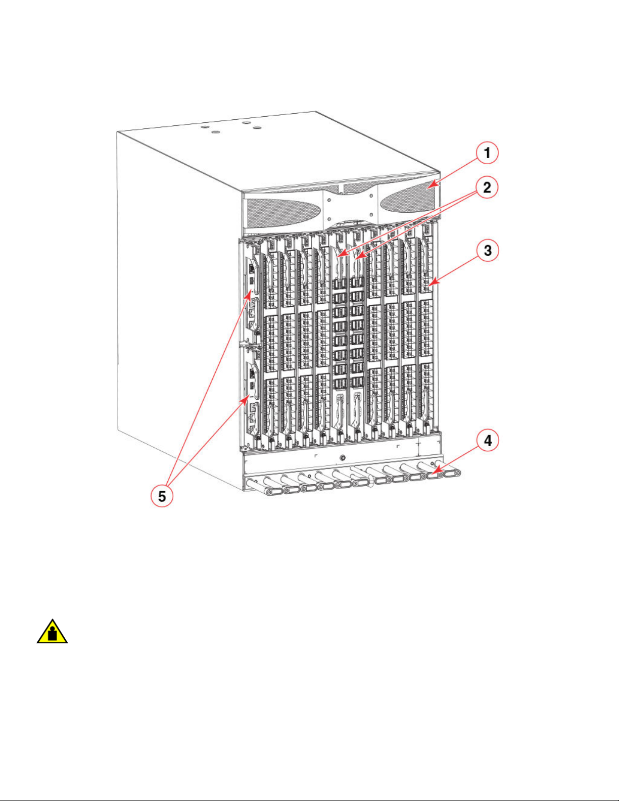
FIGURE 1 Port side of the Brocade X6-8 Director (sample conguration)
Port-side view of device
1. Air vent
2. Core routing blades (CR32-8)
3. Port blades (FC32-48)
4. Cable management comb
5. Control processor blades (CPX6) – slot 1 (upper), slot 2 (lower)
NOTE
Depending on the fans and power supplies installed, airow can be from the port side to the nonport side of chassis or from
the nonport side to the port side of the chassis.
CAUTION
Do not attempt to lift or support the chassis by the logo bezel attached over the port-side air vents.
Brocade X6-8 Director Hardware Installation Guide
53-1004105-07 17
Page 18

Port-side slot numbering
Port-side slot numbering
The Brocade X6-8 Director contains 10 full-height slots and two half-height slots, for a total of 12 slots. Facing the port side of the
device, the half-height slots are on the left, numbered 1 (top slot) and 2 (bottom slot). The remaining full-height slots are numbered 3
through 12, counting from left to right of chassis.
Slots contain guide pins and connectors designed for specic blade types. Only install the control processor (CP), core routing (CR), port,
and extension blades into slot numbers as follows:
• Slots 1– 2 are restricted to CP blades. Note that the blade installed in slot 1 will be designated as CP0, while the blade in slot 2
will be designated as CP1 in CLI command and message output.
• Slots 3–6 and slots 9–12 are restricted to port and extension blades.
• Slots 7– 8 are restricted to CR32-8 blades.
Nonport-side view of the device
The following illustration shows the nonport-side view of the Brocade X6-8 Director with all fan and power supply assemblies installed.
18 53-1004105-07
Brocade X6-8 Director Hardware Installation Guide
Page 19
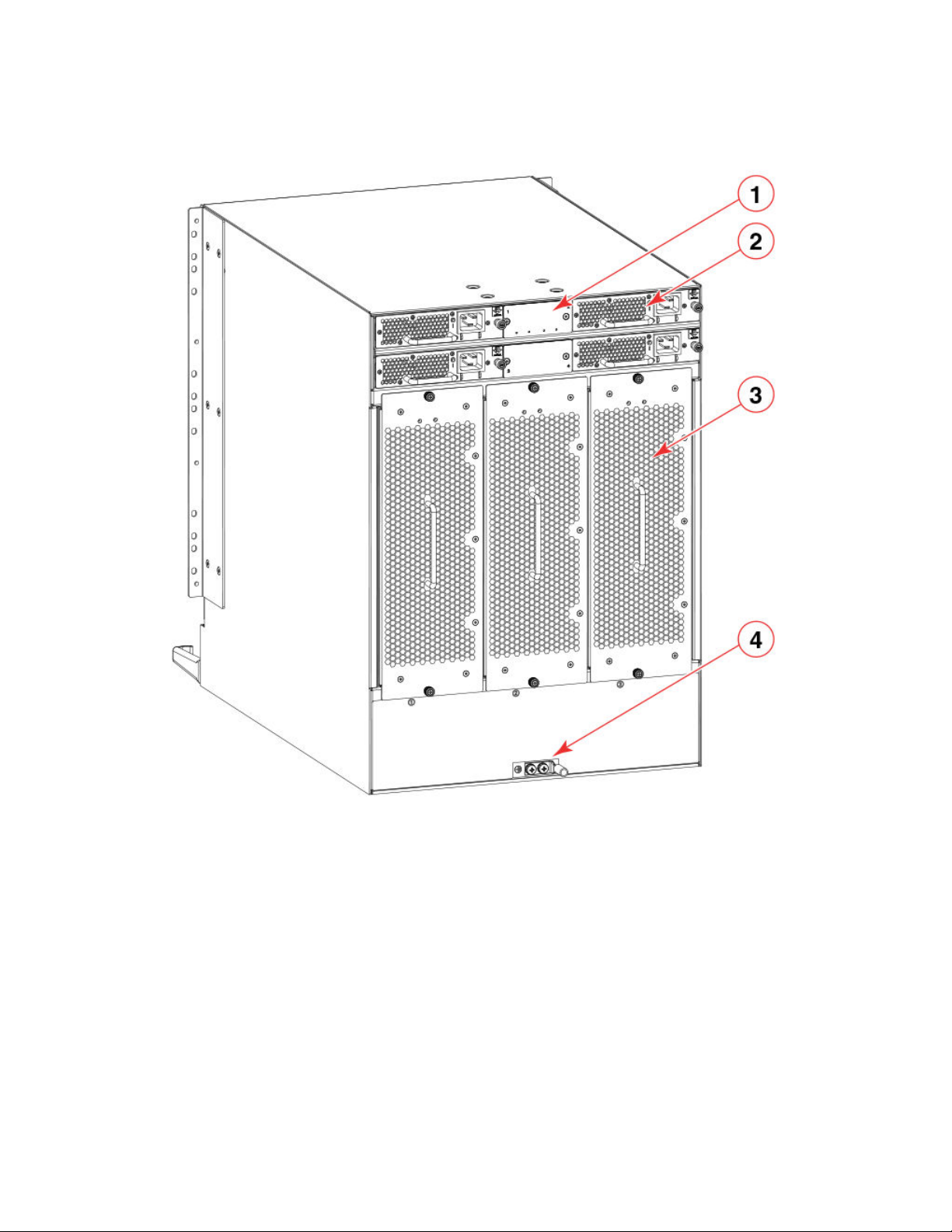
FIGURE 2 Nonport side of the Brocade X6-8 Director (sample conguration)
Nonport-side view of the device
1. WWN bezel (logo plate - WWN cards behind)
2. Power supply assembly
3. Fan assembly
4. 2AWG Panduit LCD2-14AF lug for building ground connection
Depending on fans and power supplies installed, airow can be from the port side to the nonport side of the chassis or the nonport side
to the port side of chassis.
Although not illustrated, the chassis label containing the serial number, SKU, and WWN is located on the lower portion of the chassis,
below the fan assemblies.
Brocade X6-8 Director Hardware Installation Guide
53-1004105-07 19
Page 20

20 53-1004105-07
Brocade X6-8 Director Hardware Installation Guide
Page 21

Preparing for the Installation
• Safety precautions.............................................................................................................................................................................................21
• Facility requirements.........................................................................................................................................................................................23
• Time and items required for installation...................................................................................................................................................24
• Quick installation checklists...........................................................................................................................................................................25
• Items shipped......................................................................................................................................................................................................26
Safety precautions
When using this product, observe all danger, caution, and attention notices in this manual. The safety notices are accompanied by
symbols that represent the severity of the safety condition
Refer to the Cautions and Danger Notices at the end of this guide for translations of safety notices for this product.
General precautions
DANGER
The procedures in this manual are for qualied service personnel.
DANGER
Before beginning the installation, see the precautions in “Power precautions.”
CAUTION
Changes or modications made to this device that are not expressly approved by the party responsible for compliance
could void the user's authority to operate the equipment.
CAUTION
Disassembling any part of the power supply and fan assembly voids the warranty and regulatory certications. There are no
user-serviceable parts inside the power supply and fan assembly.
CAUTION
Make sure the airow around the front, and back of the device is not
restricted.
CAUTION
To protect the serial port from damage, keep the cover on the port when not in use.
CAUTION
Never leave tools inside the chassis.
CAUTION
Use the screws specied in the procedure. Using longer screws can damage the
device.
Brocade X6-8 Director Hardware Installation Guide
53-1004105-07 21
Page 22
Safety precautions
ESD precautions
DANGER
For safety reasons, the ESD wrist strap should contain a series 1 megaohm resistor.
Power precautions
DANGER
If the installation requires a dierent power cord than the one supplied with the device, make sure you use a power cord
displaying the mark of the safety agency that denes the regulations for power cords in your country. The mark is your
assurance that the power cord can be used safely with the device.
DANGER
Make sure that the power source circuits are properly grounded, then use the power cord supplied with the device to
connect it to the power source.
CAUTION
Use a separate branch circuit for each power cord, which provides redundancy in case one of the circuits fails.
DANGER
High Touch Current. Earth connection essential before connecting supply.
CAUTION
All devices with AC power sources are intended for installation in restricted access areas only. A restricted access area is a
location where access can be gained only by trained service personnel through the use of a special tool, lock and key, or
other means of security.
CAUTION
The maximum input voltage for connection to the HVAC/HVDC power supply should not exceed 305 VAC and 400 VDC.
CAUTION
The maximum input voltage for connection to the HVAC/HVDC power supply should not exceed 305 VAC and 400 VDC .
CAUTION
For removal of the metal cable restraint cover under the high voltage power supply inlet, remove the 2 Torx screws.
Lifting precautions
DANGER
Use safe lifting practices when moving the product.
DANGER
A fully populated chassis weighs approximately 145.83 kg (321.5 lbs) and requires a hydraulic or assisted lift to install it.
CAUTION
Do not attempt to lift or support the chassis by the logo bezel attached over the port-side air vents.
22 53-1004105-07
Brocade X6-8 Director Hardware Installation Guide
Page 23

Facility requirements
Laser precautions
DANGER
All ber-optic interfaces use Class 1 lasers.
DANGER
Laser Radiation. Do Not View Directly with Optical Instruments. Class 1M Laser Products.
DANGER
Use only optical transceivers that are qualied by Brocade Communications Systems, Inc. and comply with the FDA Class
1 radiation performance requirements dened in 21 CFR Subchapter I, and with IEC 60825 and EN60825. Optical
products that do not comply with these standards might emit light that is hazardous to the eyes.
Facility requirements
Before installing the device, be sure the following facilities requirements are met.
TABLE 3 Facility requirements
Type Requirements
Device specications Ensure that the facility can accommodate system, power, and environmental specications for this device as
outlined in the Brocade X6 Directors Technical Specications on page 217.
Electrical Ensure that there are dedicated electrical branch circuits with the following characteristics are available:
• Four branch circuits are highly recommended to power supplies for high availability and maximum
blade usage.
• Four cables for VAC high line or VAC low line operation.
• Two cables for DC operation.
• Protected by a circuit breaker in accordance with local electrical codes.
• Supply circuit, line fusing, and wire size adequate to the electrical rating on the chassis nameplate.
• Location close to the chassis and easily accessible.
• Grounded outlets installed by a licensed electrician and compatible with the power cords.
Ensure that all equipment in rack is grounded through a reliable branch circuit connection.
Make sure that power distribution units (PDUs) can handle maximum input amperage of power supplies. Use
cables with adequate amperage rating from PDUs to power source.
Thermal Ensure that the air intake and exhaust vents have a minimum of 5.1 cm (2 in.) of airspace.
Ensure that the air intake temperature is less than 40°C (104°F) during operation.
Rack (when rack-mounted) Ensure that these airow requirements are met:
• Plan to install the device with the air-intake side facing the cool air aisle. The device can be installed
facing either direction if serviceability and cooling requirements are met.
• Ensure that the airow available at the air vents meets the minimum requirements for the device.
• Install the device with the airow aligned with other devices in the rack. Some devices have airow
running from port side to nonport side and others have the opposite arrangement. Make sure that the
airow for all devices moves in the same direction to maximize cooling.
Ensure that the following amount of space is available in the rack:
• 14 rack units (14U) high. 1U is equal to 4.45 cm (1.75 inches).
• 61.29 cm (24.09 inch) deep.
• 43.74 cm (17.22 inch) wide.
Brocade X6-8 Director Hardware Installation Guide
53-1004105-07 23
Page 24

Time and items required for installation
TABLE 3 Facility requirements (continued)
Type Requirements
Ensure that the rack meets these additional requirements:
• Additional weight of chassis will not exceed the rack’s weight limits.
• The rack is secured to ensure stability in case of unexpected movement.
Time and items required for installation
You can set up and install the device in the following ways:
• As a standalone unit on a at surface.
• In a 19-inch Electronic Industries Association (EIA) rack or in a telecommunications (Telco) rack using a Brocade rack mount kit.
Refer to Mounting options on page 29 for applicable rack mount kits.
The following table describes the main installation and setup tasks, the estimated time required for each, and the items required to
complete the task for a device that is fully populated with port blades. Congurations with fewer blades or ports require less time. These
time estimates assume a prepared installation site and appropriate power and network connectivity.
TABLE 4 Installation tasks, time, and items required
Installation task Time estimate Items required
Site preparation and unpacking the device. 30 minutes 1/2-in. socket wrench (optional).
#1 and #2 Phillips screwdrivers.
Pallet jack.
Hydraulic lift or assisted lift, able to raise to a minimum of
140 cm (55 in.), with a minimum capacity of 115 kg (254
lb).
To nd the weight of your device fully populated with the
required port blades, refer to Brocade X6 Directors
Technical Specications on page 217.
Installing rack mount kit . 30 minutes Refer the procedures for your rack mount kit located in this
Mounting and securing the device in rack. 30 minutes
Installing power cables and powering on the device. 20 minutes Power cables. These are ordered and shipped separately
Establishing serial connection, logging in to the device, and
conguring IP addresses.
Installing an Ethernet cable, opening a Telnet session, and
conguring the device domain ID, date and time, and
additional system parameters. Verify and back up
conguration.
Installing transceivers as needed. 20-30 minutes or longer if
Attaching ber-optic cables, cable ties, and cable guides. 2-3 hours Fiber-optic cables, cable ties, and cable management
20 minutes Serial cable (provided in the accessory kit).
20 minutes Ethernet cabling (optional) for Telnet access.
you are using high-density
port blades.
guide.
based on country where device is installed.
Workstation computer with a serial port or terminal server
port and a terminal emulator application (such as
HyperTerminal).
Ethernet IP addresses for the device and for both control
processor blades; total of three addresses.
Refer to the Brocade Fabric OS Administration Guide.
SFP+ and QSFP28 optical transceivers as needed.
comb.
24 53-1004105-07
Brocade X6-8 Director Hardware Installation Guide
Page 25

Quick installation checklists
Quick installation checklists
These checklists provides a high-level overview of the basic installation process from the planning stage to the point where the device
comes online and is ready to be deployed. Completing all the tasks in the suggested order ensures successful installation. Brocade
recommends that you print these checklists and take them to the installation site.
Pre-installation tasks
Review all installation requirements ahead of time as part of your site preparation. Careful planning and site preparation ensures seamless
installation, especially when installing multiple devices.
TABLE 5 Installation prerequisites
Task Task details or additional information Completed
Unpack the device. Take an inventory of the hardware components included in your shipment. Refer to Items
shipped on page 26.
Gather necessary components and
required tools.
Review the safety precautions. Refer to Safety precautions on page 21.
Plan the installation. Obtain the appropriate rack mount kit. Refer to Mounting options on page 29.
Review and verify installation requirements. Verify that the following requirements are met. Refer to Facility requirements on page 23.
Gather network conguration parameters.
Review the time and items required information at the beginning of the following sections
in this guide to ensure you have gathered all necessary components required:
• Mounting the Device
• Initial Setup and Verication
• Port and Extension Blades (if required to install)
• Power Supplies (if required to install)
• Electrical
• Environmental
• Rack
• Thermal
• IP address
• Subnet mask
• Default gateway
• Domain ID
• Time zone
Installation and initial conguration
The initial setup includes mounting the device on a at surface or in a rack and completing the conguration tasks necessary to bring the
device online and verify the operation.
TABLE 6 Installation and basic system
Task Task details or additional information Completed
Install blades or power supply assemblies Install any blades or power supply assemblies that have shipped separately from the
Mount the device Choose one of the following mounting options:
Brocade X6-8 Director Hardware Installation Guide
53-1004105-07 25
conguration
chassis. Be sure to use a #1 Phillips screwdriver for captive screws to lock these FRUs
into place.
• Mount the device in a four-post rack. Refer to the instructions in this guide for
mounting your device in a four-post rack.
Page 26

Items shipped
TABLE 6 Installation and basic system conguration (continued)
Task Task details or additional information Completed
• Mount the device in a two-post rack. Refer to the instructions in this guide for
mounting your device in a two-post rack.
Check the airow of the power supply and
fan assembly
Gather all components required for the
initial setup
Provide power to the device Refer to Connecting power cord to AC power supplies on page 49.
Attach a management station, establish a
serial connection, and change the default
passwords (optional)
Set the IP address, subnet mask, and the
default gateway IP address
Set the date and time
Customize the switch name and chassis
name
Establish an Ethernet connection By establishing an Ethernet connection, you can complete the device conguration using
Optional: Congure the DNS service Use the dnscong command to create DNS server entries. Refer to the Brocade Fabric
Optional: Customize the domain ID Use the congure command to change the domain ID (default ID is 1). Refer to Setting
Verify that the device operates correctly
Back up the conguration Use the interactive congupload command to back up the conguration. Refer to
Optional: Power o the devices Enter the shutdown command and wait for the device to power down, and then unplug
The airow direction of the power supply and fan should match. The power supplies and
fan trays are clearly labeled with either a green arrow with an "E", or an orange arrow with
an "I." For more details, refer to Fan and power supply airow on page 176.
Refer to Items required on page 48.
Refer to Establishing a serial connection to the device on page 55. After completing this
task, log in to the serial port to congure the device.
Use the ipaddrset command to congure a static device IP address, subnet mask, and
gateway IP address, or you can use a DHCP server to obtain the information dynamically.
Refer to Conguring the IP addresses on page 56.
• Use the date command to display and set the date and time.
• Use the tstimezone command to display and set the time zone.
• Use the tsclockserver command to synchronize the time with an external NTP
server.
Refer to Setting the date and time on page 59 for more information.
• Use the switchname command to change the default switch name.
• Use the chassisname command to change the default chassis name.
Refer to Customizing the chassis and switch name on page 62 for more information.
a serial session, Telnet, or management application, such as Brocade Network Advisor.
Refer to Establishing an Ethernet connection to the device on page 58.
OS Administration Guide.
the domain ID on page 59 for more information.
• Check the LEDs to verify operation of functional parts. Refer to the Monitoring
the Device section of this guide.
• The following commands can be useful to establish an operational baseline for
the device. Refer to the Brocade Fabric OS Command Reference for more
information on these commands.
– psshow
– fanshow
– tempshow
– historyshow
– errdump
Backing up the conguration on page 64 for more information.
the power cords. Refer to Powering down the chassis on page 65 for more information.
Items shipped
When unpacking the device, follow procedures under "Unpacking and transporting the device". Verify that you have the following items.
Save shipping cartons and packaging in the event you need to return the device.
26 53-1004105-07
Brocade X6-8 Director Hardware Installation Guide
Page 27

Packaged in device shipping carton:
• Brocade X6 Director with shipping tray
• Packing foam
• Antistatic plastic
• Inner foam
Packaged in device shipping carton or separate carton.
• Door (for EMI compliance)
• Power cords as ordered for installed power supplies
• Serial cable
• ESD wrist strap
• SFP extraction tool
• Power cord retainer clips
• Cable management comb assembly
• 4 GB USB drive
• China-RoHS Hazardous/Toxic Substance statement
• Network Advisor web pointer card
• Brocade documentation web pointer card
• Rack mount kit for your device
• Ground lug kit
Items shipped
Brocade X6-8 Director Hardware Installation Guide
53-1004105-07 27
Page 28

28 53-1004105-07
Brocade X6-8 Director Hardware Installation Guide
Page 29

Mounting the Device
• Mounting options...............................................................................................................................................................................................29
• Mounting precautions......................................................................................................................................................................................29
• Unpacking and transporting the device....................................................................................................................................................30
• Installing the 14U Rack Mount Kit for Four-Post Racks (XBR-DCX-0120 and XBR-DCX-0152) ............................ 31
• Installing the 14U Chassis Mid-Mount Rack Kit for Two-Post Racks (XBR-DCX-0121).................................................39
• Removing logo bezel protective cover......................................................................................................................................................45
Mounting options
You can mount the device in the following locations:
• As a standalone unit on a at surface, such as a table top.
• In a four-post 19 in. (48.3 cm) EIA rack:
– Use the 14U rack mount kit for four-post racks (XBR-DCX-0120), which contains shelf brackets that telescope from 27 in.
(68.58 cm) to 31 in. (78.74 cm) to t the majority of racks.
– Use the 14U rack mount kit for four-post racks (XBR-DCX-0152), which contains 22 in. (55.88 cm) xed shelf brackets
designed for specic racks.
– Refer to Installing the 14U Rack Mount Kit for Four-Post Racks (XBR-DCX-0120 and XBR-DCX-0152) on page 31 for
instructions.
• In a two-post Telco rack:
– Use the 14U mid-mount rack kit for two-post racks (XBR-DCX-0121).
– Refer to Installing the 14U Chassis Mid-Mount Rack Kit for Two-Post Racks (XBR-DCX-0121) on page 39 for
instructions .
NOTE
Review the Mounting precautions on page 29 before mounting the device and ensure that all Facility requirements on page
23 are met.
NOTE
The preceding rack mount kits are supported for these devices on the publication date of this guide. For current support
information, contact your Brocade representative.
Mounting precautions
The following precautions
CAUTION
Do not use the port cover tabs to lift the module. They are not designed to support the weight of the module, which can fall
and be damaged.
CAUTION
Make sure the airow around the front, and back of the device is not
restricted.
Brocade X6-8 Director Hardware Installation Guide
53-1004105-07 29
specically apply to mounting the device.
Page 30
Unpacking and transporting the device
DANGER
Mount the devices you install in a rack as low as possible. Place the heaviest device at the bottom and progressively place
lighter devices above.
DANGER
Use safe lifting practices when moving the product.
CAUTION
To prevent damage to the chassis and components, never attempt to lift the chassis using the fan or power supply handles.
These handles were not designed to support the weight of the chassis.
CAUTION
Do not attempt to lift or support the chassis by the logo bezel attached over the port-side air vents.
NOTE
You can connect the device to building ground by connecting an appropriate 2 AWG wire from a grounded connection to the
2AWG Panduit LCD2-14AF lug on the nonport-side of the device.
Unpacking and transporting the device
Use the following procedure to unpack and install your device.
DANGER
A fully populated chassis weighs approximately 145.83 kg (321.5 lbs) and requires a hydraulic or assisted lift to install it.
1. Unpack the device.
a) Cut the bands that encircle the packaging.
b) Open the top of the shipping box and remove accessory kit, rack mount kits, and foam from the top of the device.
c) Lift the cardboard shipping container and inner cardboard sleeve o the device.
d) Remove the antistatic plastic o the device.
e) Leave the device on top the foam shipping tray and wood pallet if the device must be transported to the installation
location.
f) Verify the contents of the shipping carton by referring to Items shipped on page 26.
g) Save foam packing material and wooden pallet for reuse.
2. Use a pallet jack or other assisted lift to transport the device to the installation area. Doorways must be wider than 36 in. (91
cm) to accommodate the device.
3. Remove the chassis door if installed.
4. Remove the cable management comb if attached to the device.
30 53-1004105-07
Brocade X6-8 Director Hardware Installation Guide
Page 31

Installing the 14U Rack Mount Kit for Four-Post Racks (XBR-DCX-0120 and XBR-DCX-0152)
5. Use a lift to raise the device to the correct level. Use two people, one to operate the lift and the other to secure the device on the
lift.
CAUTION
Do not attempt to lift or support the chassis by the logo bezel attached over the port-side air vents.
NOTE
Orient the device on the lift so that you can slide it into correct side of rack to provide cool air intake. Fans and power
supply FRUs in this device have a green "E" or "I" symbol on the FRU faceplate. An "E" indicates that the FRU pulls air
from the port side of the device and exhausts out the nonport side. An "I" indicates that the FRU pulls air from the
nonport side of the device and exhausts out the nonport side. Fans and power supplies must have the same airow
indicator. Be sure that you are pulling cool air into the air intake side of the device. For more details, refer to Fan and
power supply airow on page 176.
6. If applicable, lock the wheels of the lift.
7. Install the applicable rack mount kit in your equipment rack and mount the device using the rack mount kit's installation
instructions.
NOTE
When installing the device into the rack, use one person on each side of the device to gently slide it onto the nal
installation surface and ensure that it remains supported during the transfer.
8. Reinstall the cable management comb if you removed it.
9. Reinstall the chassis door. The door must be installed to meet EMI compliance.
Installing the 14U Rack Mount Kit for Four-Post
Racks (XBR-DCX-0120 and XBR-DCX-0152)
Use the following instructions to install a modular device in a 19-in. (48.3 cm) EIA rack using the 14U Rack Mount Kit for Four-Post
Racks (XBR-DCX-0120 and XBR-DCX-0152).
Two rack-mount kits are available.
• XBR-DCX-0120 - Contains shelf brackets that telescope from 27 in. (68.58 cm) to 31 in. (78.74 cm) to
racks.
• XBR-DCX-0152 - Contains 22 in. (55.88 cm) xed shelf brackets that adjust to 27 in. (68.58 cm).
Observe the following when mounting this device:
• Use Electronic Industries Association (EIA) standard racks. Ensure that the space in the 19-in. (48.3 cm) EIA rack is 14U high.
• Verify that the additional weight of the chassis does not exceed the weight limits of the rack.
• Before mounting your device, review any specic installation and facility requirements in this Hardware Installation Guide.
• Hardware devices illustrated in these procedures are only for reference and may not depict the device you are installing into the
rack.
t the majority of
Time and items required
Allow approximately one hour to unpack and install a device in a rack.
Brocade X6-8 Director Hardware Installation Guide
53-1004105-07 31
Page 32

Installing the 14U Rack Mount Kit for Four-Post Racks (XBR-DCX-0120 and XBR-DCX-0152)
The following tools are required when installing the 14U Rack Mount Kit for Four-Post Rack:
• Torque screwdriver with #2 Phillips screwdriver tip
• Slotted (at blade) screwdriver
• Hydraulic or assisted lift with a minimum raise of 140 cm (55 in.) and a minimum capacity of 113 kg (250 lb)
Parts list
The following table lists 14U Rack Mount Kit parts and quantities for
dierent installations. Refer to the illustration following the table to
identify these parts.
TABLE 7 14U rack mount kit parts and quantities
Description Installation Quantity
Left rack mount shelf bracket (rail brackets may dier from ones shown in illustration) All 1
Right rack mount shelf bracket (rail brackets may dier from ones shown in illustration) All 1
10-32 x 5/8 in. (1.58 cm) panhead Phillips screw and washer (torque to 32 in-lb, [37 cm-
kg])
10-32 clip nut For rack rails with round holes 6
1/4-20 x 1/2 in. (1.27 cm) panhead Phillips screw with lock washer (torque to 80 in-lb [92
cm-kg])
10-32 retainer nut For rack rails with square holes 6
1/4-20 x 1/2 in. (1.27 cm) panhead Phillips screw with thread locker (torque to 80 in-lb [92
cm-kg])
3/8 in. (0.953 cm) alignment washer For rack rails with square holes 16
All 6
For rack rails with round holes 16
For rack rails with square holes 16
NOTE
Depending on the device and installation, not all the parts may be used on the device type.
32 53-1004105-07
Brocade X6-8 Director Hardware Installation Guide
Page 33
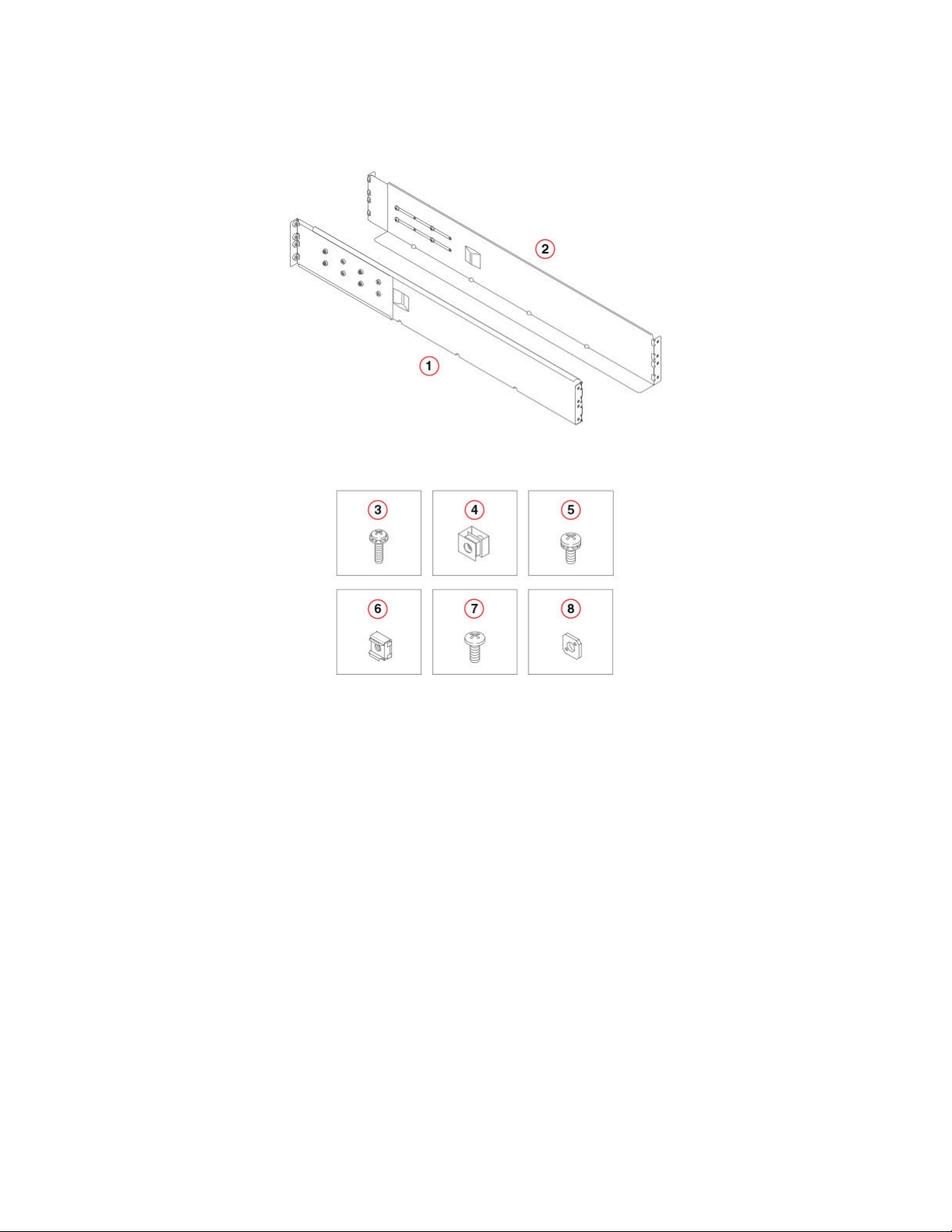
FIGURE 3 14U rack kit parts
Installing the 14U Rack Mount Kit for Four-Post Racks (XBR-DCX-0120 and XBR-DCX-0152)
1. Left rack mount shelf bracket
2. Right rack mount shelf bracket
3. 10-32 x 5/8 in. (1.58 cm) panhead Phillips screw and washer
4. 10-32 clip nut for cabinets that have rails with round holes
5. 1/4-20 x 1/2 in. (1.27 cm) panhead Phillips screw with lock washer for
cabinets that have rails with round holes
6. 10-32 retainer nut for cabinets that have rails with square holes
7. 1/4-20 x 1/2 in. (1.27 cm) panhead Phillips screw with thread locker for
cabinets that have rails with square holes
8. 3/8 in. (0.953 cm) alignment washer for cabinets that have rails with
square holes
Parts list – NEBS kit
The following table lists the parts supplied in the XBR-SLX9850-8-NEBS-KIT to help direct airow away from the rack area. This kit is
only supported for specic devices, and may not apply to the device that you are installing.
NOTE
Depending on the device and installation, not all of the parts may be used.
Verify that the items listed in the following gure are included in the NEBS kit.
Brocade X6-8 Director Hardware Installation Guide
53-1004105-07 33
Page 34

Installing the 14U Rack Mount Kit for Four-Post Racks (XBR-DCX-0120 and XBR-DCX-0152)
FIGURE 4 NEBS kit parts list
1. Left cable comb assembly (1)
2. Right cable comb assembly (1)
3. Air lter (1)
4. Chassis door (1)
5. Velcro strap (8)
6. Screw, 10-32 x .63-in., square cone washer (10)
7. Screw, 8-32 x .312 in., athead (20)
8. Nut retainer (6)
Assembling the rack hardware
Attach the left and right rack mount shelf brackets to the rack rails.
NOTE
If cables are to be routed down through the cable management comb, allow space below the brackets for cable management
1. Locate the shelf brackets in the device.
34 53-1004105-07
Brocade X6-8 Director Hardware Installation Guide
Page 35

Installing the 14U Rack Mount Kit for Four-Post Racks (XBR-DCX-0120 and XBR-DCX-0152)
2. Locate and loosen the screws on the adjustable ends of the brackets (see the following gure) to allow for adjustment to rack
depth.
FIGURE 5 Left and right shelf brackets installed on rails
1. Left rack mount shelf bracket
2. Right rack mount shelf bracket
3. 1/4-20 x 1/2 in. (1.27 cm) panhead Phillips screw with lock
washer for rails with round holes (4 on each end of each
bracket, 16 total)
4. 3/8 in. (0.953 cm) alignment washer for rails with square
holes (4 on each end of each bracket, 16 total)
5. 1/4-20 x 1/2 in. (1.27 cm) panhead Phillips screw with
thread locker for rails with square holes (4 on each end of each
bracket, 16 total)
6. Adjustable ends of shelf brackets
7. Intake air direction
8. Exhaust air direction
CAUTION
Use the screws specied in the procedure. Using longer screws can damage the
device.
Brocade X6-8 Director Hardware Installation Guide
53-1004105-07 35
Page 36

Installing the 14U Rack Mount Kit for Four-Post Racks (XBR-DCX-0120 and XBR-DCX-0152)
3. Position the shelf brackets with the adjustable ends on the intake air aisle side of the rack (see the previous gure).
• For rails with round holes:
– Position the left and right rack mount shelf brackets and attach them to the rack rails. Use eight screws with lock
washers per bracket (four on each end). Tighten the screws to a torque of 80 in-lb (92 cm-kg).
• For rails with square holes:
– Position the left and right rack mount shelf brackets and attach them to the rack rails. Use eight screws and alignment
washers per bracket (four on each end). Tighten the screws to a torque of 80 in-lb (92 cm-kg).
FIGURE 6 Nut and screw locations for mounting the device
1. 10-32 clip nuts (for round holes)
2. Rail
3. 10-32 retainer nut (for square holes)
4. Rail
5. Top screws in shelf bracket
6. Bottom screws in shelf bracket
7. Left rack mount shelf bracket
8. Right rack mount shelf bracket
9. Hole 1
NOTE
Standard EIA rails have holes in sets of three; spaces between the holes are 5/8 in., 5/8 in., and 1/2 in. (1.58 cm,
1.58 cm, and 1.27 cm).
4. Tighten the adjusting screws on the sliding portion of the rack mount shelf brackets to a torque of 32 in-lb (37 cm-kg).
36 53-1004105-07
Brocade X6-8 Director Hardware Installation Guide
Page 37

Installing the 14U Rack Mount Kit for Four-Post Racks (XBR-DCX-0120 and XBR-DCX-0152)
5. Attach the clip nuts (for rails with round holes) or retainer nuts (for rails with square holes) to the vertical rails on the exhaust aisle
side of the rack (see the previous gure). These clip nuts are used for securing the port side of the device to the rack rails using
10-32 x 5/8 inch screws. Use three clips on each rail. Place the clips in optimum locations for securing the device to the rails.
NOTE
Do not align the clip or retainer nuts with the top or bottom holes of the mounting bracket because the screw heads
will interfere with the door.
Installing the device in the rack
Use the following procedure to install the device in the rack.
DANGER
Use safe lifting practices when moving the product.
1. Ensure that the door, if installed, is removed from the port side of the device. For instructions, refer to instructions for removing
and replacing the device door in the device installation guide.
2. Use a lift to raise the device to the level of the shelf brackets.
3. Move the lift as close as possible to the rack, with the air-intake side of the device facing the front of the rack (see the following
gure).
4. If applicable, lock the wheels of the lift.
Brocade X6-8 Director Hardware Installation Guide
53-1004105-07 37
Page 38

Installing the 14U Rack Mount Kit for Four-Post Racks (XBR-DCX-0120 and XBR-DCX-0152)
5. Gently slide the device onto the shelf brackets, ensuring that it remains supported during the transfer.
FIGURE 7 Positioning the device for installation in a rack
1. Rack 2. Nonport side of device
38 53-1004105-07
Brocade X6-8 Director Hardware Installation Guide
Page 39
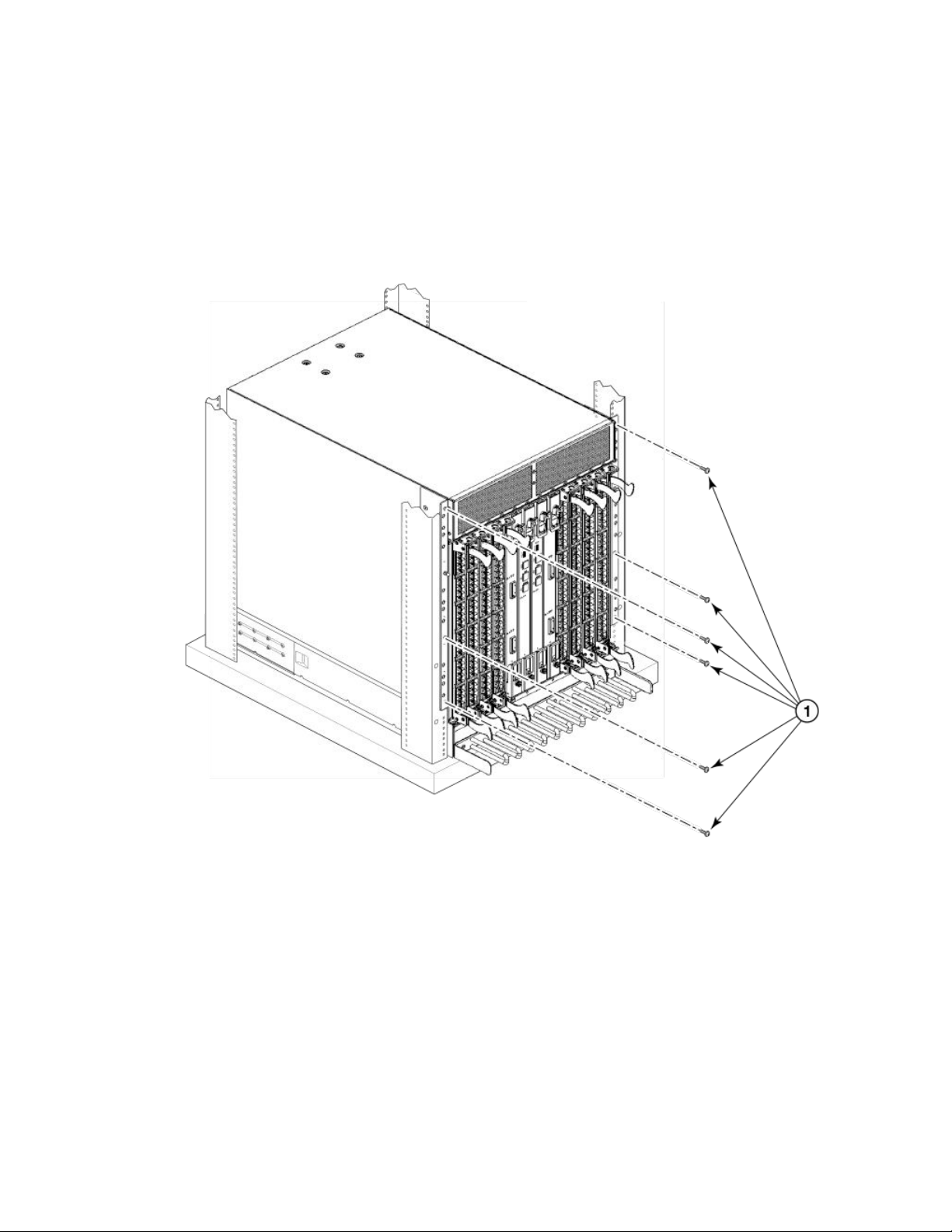
Installing the 14U Chassis Mid-Mount Rack Kit for Two-Post Racks (XBR-DCX-0121)
6. Fasten the port side of the device to the rack rails. Use three 10-32 x 5/8 inch (1.58 cm) screws per rail. Tighten the screws to
a torque of 32 in-lb (37 cm-kg). Refer to Figure 8.
NOTE
Do not use the top or bottom holes of the mounting bracket because the screw heads will interfere with the door.
FIGURE 8 Attaching port side of device to rack rails
1. 10-32 x 5/8 in. (1.58 cm) panhead Phillips screw with washer
7. Reinstall the device door if removed from your device. For instructions, refer to the door removal and replacement procedures in
your device installation guide.
Installing the 14U Chassis Mid-Mount Rack Kit for
Two-Post Racks (XBR-DCX-0121)
Use the following instructions to install a Brocade modular device in a telecommunications (Telco) rack, using the 14U Chassis MidMount Rack Kit for Two-Post Racks (XBR-DCX-0121).
Brocade X6-8 Director Hardware Installation Guide
53-1004105-07 39
Page 40

Installing the 14U Chassis Mid-Mount Rack Kit for Two-Post Racks (XBR-DCX-0121)
Observe the following when mounting this device:
• The kit is compatible with rack rails that are either 3 inches or 5 inches wide (adapters are provided for 3-in. rails).
• Before mounting your device, review any specic installation and facility requirements in this Hardware Installation Guide.
• Hardware devices illustrated in these procedures are only for reference and may not depict the device you are installing into the
rack.
Time and Items required
Allow approximately one hour to unpack and install a chassis in a rack.
The following tools are required when installing the 14U Chassis Mid-Mount Rack Kit for Two-Post Racks.
• Torque wrench with #2 Phillips screwdriver tip
• Flathead screwdriver
• Hydraulic or assisted lift with a minimum raise of 140 cm (55 in.) and a minimum capacity of 113 kg (250 lbs).
Parts list
The following parts are provided with the 14U Chassis Mid-Mount Rack Kit for Two-Post Racks (XBR-DCX-0121).
40 53-1004105-07
Brocade X6-8 Director Hardware Installation Guide
Page 41

FIGURE 9 Rack kit parts
Installing the 14U Chassis Mid-Mount Rack Kit for Two-Post Racks (XBR-DCX-0121)
1. Tray, front, mid-mount, chassis
2. Tray, rear, mid-mount, chassis
3. Adapter, rear, mid-mount, right
4. Adapter, rear, mid-mount, left
5. Screw, 10-32 x 3/8”, pan head Phillips, ST, zinc (requires a torque of 32
inch-pounds)
NOTE
Not all parts may be used with certain installations depending on the device type.
Assembling the rack hardware
Perform the following steps to assemble the rack hardware.
1. Attach the rear tray (with or without adapter, as required) to both rack rails. Orient the tray (refer the following
screws (Item E) for each rail.
2. Attach the front tray to both rack rails. Orient the tray (Figure 11) and use nine screws (Item E) for each rail.
Brocade X6-8 Director Hardware Installation Guide
53-1004105-07 41
gure) and use nine
Page 42

Installing the 14U Chassis Mid-Mount Rack Kit for Two-Post Racks (XBR-DCX-0121)
3. Verify that the rear edge of the front tray is seated into the front edge of the rear tray.
FIGURE 10 Attaching the rear tray to the rack rails
2. Tray, rear, mid-mount, chassis
3. Adapter, rear, mid-mount, right
4. Adapter, rear, mid-mount, left
5. Screws
42 53-1004105-07
Brocade X6-8 Director Hardware Installation Guide
Page 43

FIGURE 11 Attaching the front tray to the rack rails
Installing the 14U Chassis Mid-Mount Rack Kit for Two-Post Racks (XBR-DCX-0121)
1. Tray, front, mid-mount, chassis
5. Screws
Installing the device in the rack
DANGER
Use safe lifting practices when moving the product.
NOTE
A fully populated device requires a hydraulic or assisted lift to install into a rack.
Brocade X6-8 Director Hardware Installation Guide
53-1004105-07 43
Page 44

Installing the 14U Chassis Mid-Mount Rack Kit for Two-Post Racks (XBR-DCX-0121)
Perform the following steps to load the device into the mid-mount trays.
1. Ensure that the door is removed from the port side of the device. For instructions, refer to the door removal and replacement
procedures in your device installation guide.
2. Orient the device (refer the following gure) and use a hydraulic lift to raise it to the level of the trays.
3. If applicable, lock the wheels of the lift.
4. Slide the device into the trays until the front edge of the device is seated against the front tray.
FIGURE 12 Placing the device in the trays
1. Tray, front, mid-mount, chassis 2. Tray, rear, mid-mount, chassis
5. Use three screws (Item 5) to attach each side of the rear tray to the device (refer the following gure).
NOTE
The screw holes in the device walls have pem nuts on the inside surface.
44 53-1004105-07
Brocade X6-8 Director Hardware Installation Guide
Page 45

Removing logo bezel protective cover
6. Use four screws (Item 5) to attach each side of the front tray to the device
7. Use six screws (Item 5) to attach the lip on each side of the front tray to the lip on the front of the device.
NOTE
Do not use the top or bottom holes of the Brocade mounting bracket because the door will interfere with the screw
heads.
FIGURE 13 Attaching trays to the device
8. Reinstall the device door. For instructions, refer to the door removal and installation instructions in your device installation guide.
Removing logo bezel protective cover
The chassis ships with a protective cover installed over the logo bezel and air vents at the top of the port side of the chassis.
Brocade X6-8 Director Hardware Installation Guide
53-1004105-07 45
Page 46

Removing logo bezel protective cover
CAUTION
Remove the logo bezel protective cover on the port side of chassis before applying power. This cover is attached over the
air vents. If not removed, the chassis can overheat and will eventually shut down.
Remove this cover by removing the Phillips screws securing it to the mounting bracket on each side of the chassis.
FIGURE 14 Removing bezel protective cover from Brocade X6-8
CAUTION
Do not attempt to lift or support the chassis by the logo bezel attached over the port-side air vents.
46 53-1004105-07
Brocade X6-8 Director Hardware Installation Guide
Page 47

Initial Setup and Verication
• Conguration and verication task guide.................................................................................................................................................47
• Items required..................................................................................................................................................................................................... 48
• Providing power to the device......................................................................................................................................................................48
• Establishing a serial connection to the device.......................................................................................................................................55
• Conguring the IP addresses.......................................................................................................................................................................56
• Establishing an Ethernet connection to the device..............................................................................................................................58
• Setting the domain ID......................................................................................................................................................................................59
• Setting the date and time............................................................................................................................................................................... 59
• Customizing the chassis and switch name.............................................................................................................................................62
• Verifying installed licenses and license key.............................................................................................................................................63
• Verifying correct operation.............................................................................................................................................................................63
• Backing up the conguration........................................................................................................................................................................64
• Powering down the chassis...........................................................................................................................................................................65
Conguration and verication task guide
Before connecting device to the fabric, use the following tasks to initially congure and setup the device, verify correct operation, and
back up the conguration.
The conguration information is mirrored to the standby CP blade, which allows the current conguration to remain available even if the
active CP blade fails. The conguration information for the device is stored in the WWN cards and the ash memory of the CP blades.
The conguration can be backed up to a workstation (uploaded) and then downloaded to the active CP blade if necessary.
NOTE
The device WWN is set by the factory to match the license ID (which is based on the chassis serial number).
TABLE 8 Conguration and verication tasks
Task Task details or additional information
Establish a serial connection to the director. Connect a serial cable to the console port on active CP blade and use a terminal
emulator program (such as HyperTerminal on a PC, or TERM, TIP, or Kermit in a
UNIX environment) to log in to the console port and device. The blue "Active" LED
illuminates on the active CP blade.
Congure IP addresses for the device. Congure an IP address and subnet mask for a chassis management connection.
Congure IP addresses, host names, subnet masks, and gateway addresses for both
control processor (CP) blades.
Establishing an Ethernet connection to the device. Connect Ethernet cable to active CP blade Ethernet port labeled "Management" and
establish a connection.
Set a unique domain ID for the device. Disable the device using the switchDisable command, and then use the congure
command to step through prompts to congure a domain ID. Use switchEnable to
re-enable the device.
Set the date and time for the device. Use the date, tsTimeZone, and tsClockServer commands to set date, time zone, and
synchronize local time of device with NTP server.
Customize a switch and chassis name for the device. Use the switchName command, followed by new name in quote marks (switchname
"bigswitch".)
Use the chassisName command followed by the new name in quote marks
(chassisname "chassis_002").
Brocade X6-8 Director Hardware Installation Guide
53-1004105-07 47
Page 48

Items required
TABLE 8 Conguration and verication tasks (continued)
Task Task details or additional information
Verify installed licenses and license key Enter the licenseShow command to determine display enabled licenses and the
license key.
Enter the licenseIdShow command to obtain the chassis ID.
Record the license key and chassis ID for future reference.
Verify correct operation of director. Check LEDs on blades and FRUs, and use the following commands to verify
operation:
• psShow
• fanShow
• switchShow
• fabricShow
• slotShow
• tempShow
• historyShow
• errdump
Back up the conguration. Use the congUpload command.
Items required
The following items are required for initial setup and verication of the device:
• The device, mounted and installed with the required blades, FRUs, transceivers, and cables and is connected to a power source.
• A workstation computer with an installed terminal emulator application, such as HyperTerminal for Windows.
• An unused IP address with corresponding subnet mask and gateway address.
• A serial cable (provided) with an RJ-45 connector.
• An RJ-45 to DB-9 adapter.
• Three Ethernet cables (including one spare).
• Access to an FTP server or USB device for backing up (uploading) or downloading the device conguration or collecting
supportsave output data (optional).
• A Brocade USB drive for collecting supportsave output data (optional)
Providing power to the device
Perform the steps to provide power that are applicable to your power supply model. Observe the following for all power connections:
• Before connecting power, refer the following.
– Electrical caution and danger statements in Safety precautions on page 21 and Facility requirements on page 23
– Power supply
requirements of your device.
• Connect each power supply to a dierent power source or circuit to provide full redundancy.
• Route the power cords so they will be out of the way when connected to the power source. Ensure that the power cords have a
minimum service loop of 15.2 cm (6 in.) and are routed to avoid stress.
• Remember that power is supplied to the device as soon as the rst power supply is connected to a power source.
specications section in the Brocade X6 Directors Technical Specications on page 217 for power supply
48 53-1004105-07
Brocade X6-8 Director Hardware Installation Guide
Page 49

Providing power to the device
Connecting power cord to AC power supplies
Complete the following steps to connect the power cord from the facility AC power source to the device 's AC power supply. Before
connecting to power, be sure to observe all "Power Precautions" in Safety precautions on page 21. In addition, refer to the power supply
specications and requirements in Brocade X6 Directors Technical Specications on page 217.
1. Remove the logo bezel protective cover if it is still installed over the top air vents on the port side of the chassis. Refer to
Removing logo bezel protective cover on page 45 for instructions.
CAUTION
Remove the logo bezel protective cover on the port side of chassis before applying power. This cover is attached
over the air vents. If not removed, the chassis can overheat and will eventually shut down.
2. Install all power supplies provided for your device if not already installed. Refer to Installing a power supply on page 181 for
procedures.
3. When installing device in a rack, route power cables from power distribution units (PDUs) so they do not cover air vents in
chassis.
4. Connect the provided AC power cords to a power source with voltage of 200–240 VAC, 50/60 Hz or optionally to a power
source with voltage of 100–120 VAC, 50/60 Hz.
DANGER
High Touch Current. Earth connection essential before connecting supply.
NOTE
Use of the high-voltage line (200–240 VAC) is highly recommended because of better power-conversion eciency.
With 120 VAC primary input, the power distribution unit (PDU) supplies roughly half the available wattage, which can
limit blade and port congurations. For a "fully-loaded" chassis with maximum supported blades and optics, four
power supplies connected to 200–240 VAC lines are required for full N+N redundancy. For details on power supplies
required for operation and high availability, refer to "Power supply requirements" and "Power consumption" tables in
the Brocade X6 Directors Technical Specications on page 217.
5. Route the cords so they will be out of the way when connected to the power source. Ensure that the power cords have a
minimum service loop of 15.2 cm (6 in.) available and are routed to avoid stress.
6. Plug the power cords into power supplies. The power supply LED will light green when power is applied. Note that after one
power supply is plugged into AC power, LEDs on the remaining installed power supplies will ash green until they also have
power applied.
The director performs a power-on self-test (POST) each time it is powered on. POST takes approximately 10 minutes, during
which time status LEDs on installed blades and other FRUs may display amber. Power LEDs on all FRUs display green when
power-on self-test (POST) is complete and all FRUs are functional. You can bypass POST by using the fastBoot command.
You can also disable POST for successive reboots using the diagDisablePost command.
NOTE
Do not connect the device to the network until the IP addresses are
congured.
7. After POST is complete, verify that the power LEDs on blades and other FRUs are green.
For information about LED patterns, refer to Monitoring the Device.
8. Ground the chassis by attaching a ground wire from building ground to an appropriate crimp connector and attaching the
connector to the 2AWG Panduit LCD2-14AF lug located under the fan assemblies near the bottom of the chassis.
Brocade X6-8 Director Hardware Installation Guide
53-1004105-07 49
Page 50
Providing power to the device
Connecting power cord to HVAC/HVDC power supplies
Use steps in this section to apply power to the dual-function high-voltage AC and DC (HVAC/HVDC) power supply. This power supply
converts high-voltage DC or AC input to appropriate DC power for the device.
Make sure that you observe the electrical caution and danger statements in Safety precautions on page 21 when connecting this power
supply.
NOTE
The equipment installation must meet NEC/CEC code requirements. Consult local authorities for regulations.
NOTE
Power is supplied to the device as soon as the rst power supply is connected to a power
source.
CAUTION
The maximum input voltage for connection to the HVAC/HVDC power supply should not exceed 305 VAC and 400 VDC.
CAUTION
The maximum input voltage for connection to the HVAC/HVDC power supply should not exceed 305 VAC and 400 VDC .
1. If connecting to AC power, attach an AC power plug to the unterminated wires on the HVAC/HVDC power cord that meets your
facility and local code requirements. If connecting to DC power, verify how you will attach these unterminated wires to your site's
DC power terminal blocks. For more information on the HVAC/HVDC power cord available for these power supplies, refer to
Using HVAC/HVDC power cords on page 54.
2. Ground the chassis by attaching a ground wire from building ground to an appropriate crimp connector and attaching the
connector to the 2AWG Panduit LCD2-14AF lug located under the fan assemblies near the bottom of the chassis.
3. Remove the logo bezel protective cover if it is still installed over the top air vents on the port side of the chassis. Refer to
Removing logo bezel protective cover on page 45 for instructions.
CAUTION
Remove the logo bezel protective cover on the port side of chassis before applying power. This cover is attached
over the air vents. If not removed, the chassis can overheat and will eventually shut down.
4. Install all power supplies provided for your device if not already installed. Refer to Installing a power supply on page 181 for
procedures.
5. When installing the device in a rack, route power cables from power distribution units (PDUs) so they do not cover air vents in
chassis.
50 53-1004105-07
Brocade X6-8 Director Hardware Installation Guide
Page 51
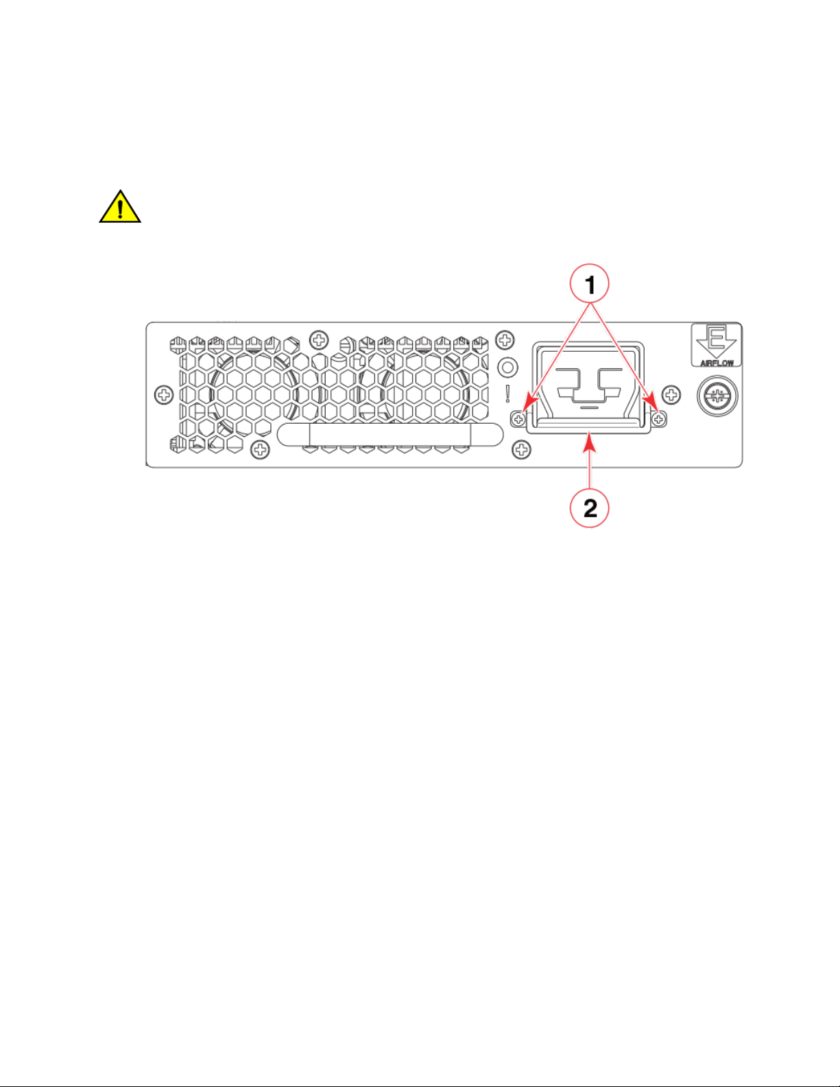
Providing power to the device
6. Before connecting the power cord to a power supply, rst remove the cable restraint cover, if it is installed under the power cord
connector. Remove the cover by unscrewing the two torx head screws.
Save the retainer cover and screws for reinstallation after plugging in the power cord.
CAUTION
When removing the metal cable restraint cover under the high voltage power supply inlet, remove the 2 Torx head
screws only.
1. Torx head screws 2. Metal cable restraint cover
Brocade X6-8 Director Hardware Installation Guide
53-1004105-07 51
Page 52

Providing power to the device
7. Connect power cords to installed power supplies.
The connector on the power cord is keyed so that it only ts one way into the power supply connector. Note that the connector's
latch should be positioned under the connector and will latch when the power cord connector is fully inserted into the power
supply.
1. Power cable 2. Connector latch
8. Attach the cable restraint cover under the power cord connector using its two torx head screws (refer to step 4).
NOTE
This retainer cover protects the power cord from being accidentally unlatched and disconnected from the power
supply.
52 53-1004105-07
Brocade X6-8 Director Hardware Installation Guide
Page 53

Providing power to the device
9. If connecting to an AC power source, use the following steps. (If connecting to a DC power source, go on to step 8.)
a) Make sure that you observe the electrical caution and danger statements in Safety precautions on page 21 when
connecting this power supply.
b) Make sure that AC power plug is attached to the power-source end of the HVAC/HVDC power cord that meets your facility
and local code requirements.
For more information on the HVAC/HVDC power cord available for these power supplies, refer to Using HVAC/HVDC
power cords on page 54.
DANGER
Make sure that the power source circuits are properly grounded, then use the power cord supplied with the
device to connect it to the power source.
c) If connecting to an AC power source, connect to a power source with voltage of 200–277 VAC, 50/60 Hz
(recommended).
NOTE
Use of a high-voltage line (200–277 VAC) is highly recommended because of better power-conversion
eciency. For a "fully-loaded" chassis with maximum supported blades and optics, four power supplies
connected to 200–277 VAC lines are required for full N+N redundancy. For details on power supplies required
for operation and high availability, refer to "Power supply requirements" and "Power consumption" tables in the
Brocade X6 Directors Technical Specications on page 217.
DANGER
High Touch Current. Earth connection essential before connecting supply.
CAUTION
Use a separate branch circuit for each power cord, which provides redundancy in case one of the circuits fails.
10. If connecting to an DC power source, use the following steps. (If connecting to a AC power source, go to step 7.)
a) Make sure that you observe applicable electrical caution and danger statements in Safety precautions on page 21 when
connecting this power supply.
b) Terminate the negative (-) and positive (+) unterminated wires on the HVAC/HVDC power cord to the DC power source.
Connect the ground wire to building ground.
For more information on the HVAC/HVDC power cord available for these power supplies, refer to Using HVAC/HVDC
power cords on page 54.
NOTE
Make sure that there is an adequate circuit breaker in the DC input circuit to the system based on input wiring to
the product and input voltage.
11. Route the cords so they will be out of the way when connected to the power source. Ensure that the power cords have a
minimum service loop of 15.2 cm (6 in.) available and are routed to avoid stress.
Brocade X6-8 Director Hardware Installation Guide
53-1004105-07 53
Page 54

Providing power to the device
12. After power is applied, the power supply LED will light green.
The director performs a power-on self-test (POST) each time it is powered on. POST takes approximately 10 minutes, during
which time status LEDs on installed blades and other FRUs may display amber. Power LEDs on all FRUs display green when
power-on self-test (POST) is complete and all FRUs are functional. You can bypass POST by using the fastBoot command.
You can also disable POST for successive reboots on the device using the diagDisablePost command.
NOTE
Do not connect the device to the network until the IP addresses are
congured.
13. After POST is complete, verify that the power LEDs on blades and other FRUs are green.
For information about LED patterns, refer to Monitoring the Device.
14. Ground the chassis by attaching a ground wire from facilities ground to an appropriate crimp connector and attaching the
connector to the 2AWG Panduit LCD2-14AF lug located under the fan assemblies near the bottom of the chassis.
Using HVAC/HVDC power cords
HVAC/HVDC power supply power cords, available from Brocade, are shipped with an Anderson Saf-D-Grid® 400 connector on the
power supply end and three unterminated 14 AWG UL 600V 90C wires with ring lugs on the power source end. Power cord length is 6
m (19 ft. 8 in.). For connecting to a power source, attach either an AC power plug to these wires that meets your facility and local code
requirements, or connect these wires to appropriate DC power terminal blocks.
The following table
denes the function of the 14 AWG wires in the power cable:
TABLE 9 HVAC/HVDC power cable
Wire label Color Function
L+ Brown Return positive (+)
– Blue Negative (-)
PE Green with yellow stripe Earth ground (PE)
The Anderson Saf-D-Grid® connector on the power supply end of the cord is keyed so that it only ts one way into the power supply.
Note that the connector's latch should be positioned under the connector and will latch when the power cord connector is fully inserted
into the power supply.
54 53-1004105-07
Brocade X6-8 Director Hardware Installation Guide
Page 55

Establishing a serial connection to the device
1. Power cable 2. Connector latch
Establishing a serial connection to the device
To establish a serial connection to the console port on the device, complete the following steps.
1. Verify that the device is powered on and that POST is complete by verifying that all power LED indicators on the power
supplies, fans, and blades display a steady green light.
2. Remove the shipping cap from the console (I0I0) port on the active CP blade. The active CP is indicated by an illuminated blue
LED on the CP blade front panel.
NOTE
The console, or serial port is intended primarily for the initial setting of the IP address and for service purposes.
3. Use the serial cable provided with the device to connect the console (serial) port on the active CP to a computer workstation.
NOTE
The active CP is indicated by an illuminated blue LED, labeled "Active," on the CP blade front panel.
If the serial port on the workstation is RJ-45 instead of RS-232, remove the adapter on the end of the serial cable and insert
the exposed RJ-45 connector into the RJ-45 serial port on the workstation.
4. Access the device using a terminal emulator application (such as HyperTerminal in a Windows environment or tip in a UNIX
environment).
5. Disable any serial communication programs running on the workstation (such as synchronization programs).
Brocade X6-8 Director Hardware Installation Guide
53-1004105-07 55
Page 56

Conguring the IP addresses
6. Open a terminal emulator application (such as HyperTerminal on a PC, or TERM, TIP, or Kermit in a UNIX environment), and
congure the application as follows:
• In a Windows environment:
Parameter Value
Bits per second 9600
Data bits 8
Parity None
Stop bits 1
Flow control None
NOTE
Flow control is not supported on the serial consoles when attached to remote terminal servers and must be
disabled on the customer-side remote terminal server and the host-side clients.
• In a UNIX environment, enter the following string at the prompt:
tip /dev/ttyb -9600
If ttyb is already in use, use ttya -9600 instead.
When the terminal emulator application stops reporting information, press Enter. The following login prompt displays:
CP0 Console Login:
NOTE
CP0 in the preceding prompt is an example. "CP1" will display if it is the active CP.
7. Log in to the console using admin as the default login name and password as the default password.
As login to the device occurs, you are prompted to change the device passwords.
Please change passwords for switch default accounts now.
Use Control-C to exit or press 'Enter' key to proceed.
8. Press Enter to step through a procedure to change the passwords as shown in the following example. To skip modifying the
password, press Ctrl+C.
----------------------------------------------------for user - admin
Changing password for admin
Enter old password:
Enter new password:
Re-type new password:
passwd: all authentication tokens updated successfully
Passwords can be 8 to 40 characters long. They must begin with an alphabetic character. They can include numeric characters,
periods (.), and underscores (_) only. Passwords are case-sensitive, and they are not displayed when you enter them on the
command line. For more information on passwords, refer to the Brocade Fabric OS Administration Guide.
Conguring the IP addresses
The device requires three IP addresses, which are
blades (CP0 and CP1) and for chassis management (shown as SWITCH under the ipaddrshow command) in the device.
56 53-1004105-07
congured using the ipaddrset command. IP addresses are required for both CP
Brocade X6-8 Director Hardware Installation Guide
Page 57

Conguring the IP addresses
The default IP addresses and host names for the device are:
• 10.77.77.75 / CP0 (the CP blade in slot 1 at the time of conguration)
• 10.77.77.74 / CP1 (the CP blade in slot 2 at the time of conguration)
Use one of the following formats for IPv4 or IPv6 addressing when entering the IP address using the ipaddrset command:
• If you using an IPv4 IP address, enter the IP address in dotted decimal notation as prompted.
Ethernet IP Address: [192.168.74.102]
• If using an IPv6 address, enter the network information in colon-separated notation as prompted.
device:admin> ipaddrset -ipv6 --add 1080::8:800:200C:417A/64
NOTE
Resetting an IP address while the device has active IP trac or has management and monitoring tools running, such as DCFM,
Fabric Watch, and SNMP, can cause trac to be interrupted or stopped.
Complete the following steps to set the IP addresses for the device.
1. Log into the device through a serial console connection to the active CP blade.
The active CP is indicated by an illuminated blue LED on the blade front panel. If you are already logged through a console port,
you can determine whether you are logged into the active or standby CP by entering hashow at the prompt. The following
example shows local login at CP1, which is the active blade.
swDir:admin> hashow
Local CP (Slot 2, CP1) : Active, Warm Recovered
Remote CP (Slot 1, CP0) : Standby, Healthy
HA Enabled, Heartbeat Up, HA State Synchronized
2. Congure the chassis management IP address by entering the ipaddrset -chassis command:
swDir:admin> ipAddrSet -chassis
Enter required information at the prompts. Specify the -chassis IP address. The -sw 0 IP address is not valid on this device.
NOTE
The addresses 10.0.0.0 through 10.0.0.255 are reserved and used internally by the device. External IPs must not
use these addresses.
Following is example conguration for setting the chassis IP address.
swDir:admin> ipaddrset -chassis
DHCP [Off]:
Ethernet IP Address [10.0.0.0]:192.168.1.1
Ethernet Subnetmask [255.0.0.0]:255.255.240.0
IP address is being changed...
Brocade X6-8 Director Hardware Installation Guide
53-1004105-07 57
Page 58

Establishing an Ethernet connection to the device
3. Set up the CP0 IP address by entering the ipaddrset -cp 0 command:
swDir:admin> ipAddrSet -cp 0
Enter required information at the prompts. Following is example conguration for setting the CP0 IP address.
swDir:admin> ipaddrset -cp 0
DHCP [Off]:
Host Name [cp0]:
Ethernet IP Address [10.0.0.0]:192.168.1.2
Ethernet Subnetmask [255.0.0.0]:255.255.260.0
Gateway IP Address [10.0.0.0]:10.38.160.1
IP address is being changed...
Done.
4. Set up the CP1 IP address by entering the ipaddrset -cp 1 command:
swDir:admin> ipAddrSet -cp 1
Enter required information at the prompts. Following is example
conguration for setting the CP1 IP address.
Following is sample conguration for setting the CP1 IP address:
swDir:admin> ipaddrset -cp 1
DHCP [Off]:
Host Name [cp0]:
Ethernet IP Address [10.0.0.0]:192.168.3
Ethernet Subnetmask [255.0.0.0]:255.255.230.0
Gateway IP Address [10.0.0.0]:10.38.160.1
IP address is being changed...
Done.
Establishing an Ethernet connection to the device
After using a serial connection to
(LAN).
NOTE
Connecting the CP blades to a private network or VLAN is recommended.
After establishing an Ethernet connection, you can complete the device conguration using a serial console connection, Telnet
connection, or management applications, such as Web Tools or Brocade Network Advisor.
Perform the following steps to establish an Ethernet connection to the device.
1. Remove the shipping plug from the Ethernet port on the active CP blade.
The active CP is indicated by an illuminated blue LED on the blade front panel.
2. Insert one end of an Ethernet cable into the Management (MGMT) Ethernet port.
3. Connect the other end to an Ethernet 10/100/1000 BaseT LAN.
congure the IP addresses for the device, you can connect the active CP blade to the local area network
4. Complete any additional device conguration procedures for the device using one of the following steps:
• Log into the device using a serial console connection and admin login.
• Log into the device through a Telnet session using the chassis management IP address and admin login.
58 53-1004105-07
Brocade X6-8 Director Hardware Installation Guide
Page 59

Setting the date and time
Setting the domain ID
Each device in the fabric must have a unique domain ID. The default domain ID is 1. If the device is not powered on until after it is
connected to the fabric and the default domain ID is already in use, the domain ID for the new device is automatically reset to a unique
value. If the device is connected to the fabric after it has been powered on and the default domain ID is already in use, the fabric
segments.
You can use the fabricshow command on another device in the fabric to view domain IDs already assigned. Manually congure a unique
domain ID using the congure command as in the following steps:
1. Log into the device using one of the following methods:
• A serial console connection to the active CP blade. The active CP is indicated by an illuminated blue LED on the blade front
panel.
• A Telnet session using the chassis management IP address.
2. Log into the device using admin as your password. If you have not changed the default password, usepassword.
3. Perform the following steps to modify the Domain ID.
a) Disable the device by entering the switchdisable command.
b) Enter the congure command. The command prompts display sequentially. Enter a new value or press Enter to accept
each default value.
c) Enter y after the "Fabric param" prompt.
Fabric param (yes, y, no, n): [no] y
d) Enter a unique domain ID (such as the domain ID used by the previous device, if still available).
Domain: (1..239) [1] 3
e) Complete the remaining prompts or press Ctrl+D to accept the remaining settings without completing all the prompts.
f) Re-enable the device by entering the switchenable command.
Setting the date and time
The date and time settings are used for logging events, error detection, and troubleshooting, and hence you should set them correctly.
However, device operation does not depend on the date and time; a device with incorrect date or time values still functions properly.
You can synchronize the local time of the principal or primary fabric
Protocol (NTP) server.
Perform the following steps to set the date and time.
1. Log into the device using one of the following methods:
• A serial console connection to the active CP blade. The active CP is indicated by an illuminated blue LED on the blade front
panel.
• A Telnet session using the chassis management IP address.
2. Log into the device using admin. If you have not changed the default password, usepassword.
conguration server (FCS) device to that of an external Network Time
Brocade X6-8 Director Hardware Installation Guide
53-1004105-07 59
Page 60

Setting the date and time
3. Enter the date command, using the following syntax:
date "mmddHHMMyy"
The values are:
• mm is the month; valid values are 01 through 12.
• dd is the date; valid values are 01 through 31.
• HH is the hour; valid values are 00 through 23.
• MM is minutes; valid values are 00 through 59.
• yy is the year; valid values are 00 through 99 (values greater than 69 are interpreted as 1970 through 1999, and values
less than 70 are interpreted as 2000 through 2069).
switch:admin> date
Fri Sep 28 17:01:48 UTC 2016
switch:admin> date "0927123016"
Thu Sep 27 12:30:00 UTC 2016
switch:admin>
Setting the time zone
The default time zone is Coordinated Universal Time (UTC). The time zone needs to be set only once because the value is stored in
nonvolatile memory. Use the following procedure to set the time zone. The time zone change will take
aect after the next system reboot.
1. Log into the device using one of the following methods:
• A serial console connection to the active CP blade. The active CP is indicated by an illuminated blue LED on the blade front
panel.
• A Telnet session using the chassis management IP address.
2. Log into the device using admin. If you have not changed the default password, usepassword.
60 53-1004105-07
Brocade X6-8 Director Hardware Installation Guide
Page 61

Setting the date and time
3. Use one of the following steps for the tsTimeZone command.
• Enter tsTimeZone --interactive command, enter the appropriate number as shown in the following example, then follow
prompts.
sw0:admin> tstimezone --interactive
Please identify a location so that time zone rules can be set correctly.
Please select a continent or ocean.
1) Africa
2) Americas
3) Antarctica
4) Arctic Ocean
5) Asia
6) Atlantic Ocean
7) Australia
8) Europe
9) Indian Ocean
10) Pacific Ocean
11) none - I want to specify the time zone using the POSIX TZ format.
Enter number or control-D to quit ?
• Enter tsTimeZone [
houroset [, minuteoset]] command as follows:
– For Pacic Standard Time, enter tsTimeZone -8,0.
– For Central Standard Time, enter tsTimeZone -6,0.
– For Eastern Standard Time, enter tsTimeZone -5,0.
TABLE 10 Example: tsTimeZone command parameter selection for the US time zones
Local time tsTimeZone parameter (dierence from UTC)
Atlantic Standard -4,0
Atlantic Daylight -3,0
Eastern Standard -5,0
Eastern Daylight -4,0
Central Standard -6,0
Central Daylight -5,0
Mountain Standard -7,0
Mountain Daylight -6,0
Pacic Standard -8,0
Pacic Daylight -7,0
Alaskan Standard -9,0
Alaskan Daylight -8,0
Hawaiian Standard -10,0
• Enter the tsTimeZone command followed by the time zone, such as US/Pacic, US/Central, or US/Eastern as in the
following example.
switch_99:Admin> tstimezone US/Pacific
System Time Zone change will take effect at next reboot
Brocade X6-8 Director Hardware Installation Guide
53-1004105-07 61
Page 62

Customizing the chassis and switch name
Synchronizing local time with an external source
Perform the following steps to synchronize the local time of the principal or primary FCS device with that of an external NTP server.
1. Log into the device using one of the following methods:
• A serial console connection to the active CP blade. The active CP is indicated by an illuminated blue LED on the blade front
panel.
• A Telnet session using the chassis management IP address.
2. Log into the device using admin. If you have not changed the default password, usepassword.
3. Enter the tsClockServer ipaddr command.
The ipaddr variable represents the IP address of the NTP server that the device can access. This argument is optional; by
default, the value is "LOCL".
switch:admin> tsclockserver 192.168.126.60
Updating Clock Server configuration...done.
Updated with the NTP servers
Customizing the chassis and switch name
Refer to the considerations and rules for creating switch, fabric, and chassis names listed in the Fabric OS Administration Guide.
NOTE
Changing the name causes a domain address format RSCN to be issued.
1. Log into the device using one of the following methods:
• A serial console connection to the active CP blade. The active CP is indicated by an illuminated blue LED on the blade front
panel.
• A Telnet session using the chassis management IP address.
2. Log into the device using admin as your password. If you have not changed the default password, usepassword.
3. Enter chassisName followed by the new name.
switch:admin> chassisname Chassis_01
A message displays explaining that the chassis name change is applied and the new name will display at next login. You can
enter chassisName to verify the new name after login.
4. To change the switch name, enter switchName followed by the new name.
swDir:admin> switchName Switch_01
Committing configuration...
Done.
Switch name has been changed.Please re-login into the switch for the
change to be applied.
A message displays that the name change is applied and the new name will display at next login. You can enter switchName to
verify the new name after login.
5. Record the new names for future references.
62 53-1004105-07
Brocade X6-8 Director Hardware Installation Guide
Page 63

Verifying correct operation
Verifying installed licenses and license key
Depending on the vendor agreement, certain licenses are factory installed on the device. Use the following steps to list installed licenses
and to record your license key and chassis ID for future reference.
1. Log into the device using one of the following methods:
• A serial console connection to the active CP blade. The active CP is indicated by an illuminated blue LED on the blade front
panel.
• A Telnet session using the chassis management IP address.
2. Log into the device using admin as your password. If you have not changed the default password, usepassword.
3. Enter the licenseShow command to determine which licenses are enabled.
This will list installed licenses and display a license key, such as aNYtMJg7tcMZrTZ9JTXBC4SXWLJMY3QfBKYHG.
4. Enter the licenseIdShow command on the active CP blade to obtain the chassis ID.
The chassis ID is required to obtain and activate licenses for the device.
5. Record the license key and chassis ID for future reference.
Refer to the Brocade Fabric OS Software Licensing Guide for more information.
Verifying correct operation
Perform the following steps to verify correct operation of the device.
1. Check the LEDs of all power supplies, fans, and blades to verify that all are functional.
2. Log into the device using one of the following methods:
• A serial console connection to the active CP blade. The active CP is indicated by an illuminated blue LED on the blade front
panel.
• A Telnet session using the chassis management IP address.
3. Log into the device using admin as your password. If you have not changed the default password, usepassword.
4. Verify the correct operation of the device by entering the following commands. Copy the output to a
Command Description
slotshow -m Displays blades (with model numbers) detected in each slot
slotshow -p Displays power consumption data and enabled status for installed blades.
psShow Displays power supply status and information
fanShow Displays fans status and information
switchShow Displays switch status and information
fabricShow Displays information about the device operation in the fabric and general information about the fabric
slotShow Displays the current status of each slot in the device
tempShow Displays temperature status and information
historyShow Displays the device history
errDump Displays any errors
le to save the information.
Brocade X6-8 Director Hardware Installation Guide
53-1004105-07 63
Page 64

Backing up the conguration
Backing up the conguration
Brocade recommends backing up the conguration on a regular basis to ensure that a complete conguration is available for
downloading to a replacement switch.
Observe the following notes about conguration data:
• Passwords are not saved in the conguration le, and are not uploaded during a conguration upload.
• It is recommended that the conguration be backed up on a regular basis to ensure that a complete conguration is available for
downloading to a replacement chassis.
• Besides saving conguration les to an FTP server or local le system, you can save to a Brocade USB device by using the
usbstorage command.
1. Log into the device using one of the following methods:
• A serial console connection to the active CP blade. The active CP is indicated by an illuminated blue LED on the blade front
panel.
• A Telnet session using the chassis management IP address.
2. Log into the device using admin as your password. If you have not changed the default password, usepassword.
3. Back up the device conguration using the congUpload command.
Follow the prompts to upload the conguration to an external host using the le transfer protocol (FTP), secure copy protocol
(SCP), or secure FTP (SFTP), or save the
conguration to the local le system on device or attached USB device.
sb_70:admin> configupload
Protocol (scp, ftp, local) [ftp]:
Server Name or IP Address [host]: 192.168.0.100
User Name [user]: anonymous
Path/Filename [<home dir>/config.txt]: /dumps/supportsave/pz/switch85/G20-1.txt
Section (all|chassis|switch [all]): all
configUpload complete: All selected config parameters are uploaded
4. Back up the virtual fabric
For more information on using the congUpload and congUpload -vf command, refer to the Brocade Fabric OS Command
Reference.
5. Enter the following commands for additional conguration information that you can save to les:
• congShow
• ipaddrShow
• licenseShow
• switchShow
conguration using the congUpload -vf command.
64 53-1004105-07
Brocade X6-8 Director Hardware Installation Guide
Page 65

Powering down the chassis
Perform the following steps to power down the chassis.
1. Shut down the chassis using the sysShutdown command.
switch::admin> sysshutdown
This command will shutdown the operating systems on your switch.
You are required to power-cycle the switch in order to restore operation.
Are you sure you want to shutdown the switch [y/n]?y
HA is disabled
Stopping blade 1
Shutting down the blade....
Stopping blade 2
Shutting down the blade....
Stopping blade 8
Shutting down the blade....
Broadcast message from root (pts/1) Tue Aug 23 14:23:06 2010...
The system is going down for system halt NOW !!
NOTE
If you do not use the sysshutdown command and you sequence power o on power distribution units (PDU) with a
few seconds between power-os, be aware that a low-power condition will be detected and logged along with
possible blade power-os before shutdown. This is an expected error condition due to delays in powering down PDUs
without halting the control processors rst using sysShutdown.
Powering down the chassis
2. Power o the chassis by disconnecting all power cords or switching o rack power source.
Note that power supply LEDs will continue to ash green briey after disconnecting power until power supply is completely o.
Brocade X6-8 Director Hardware Installation Guide
53-1004105-07 65
Page 66

Powering down the chassis
3. To disconnect power cables from HVAC/HVDC power supplies only, use the following steps.
a) Remove the cable restraint cover, if installed under the power cord connector, by unscrewing the two torx head screws.
1. Torx head screws 2. Metal cable restraint cover
CAUTION
When removing the metal cable restraint cover under the high voltage power supply inlet, remove the two Torx
head screws only.
b) Disconnect the power cable from the power supply.
Note that the latch for the power cable connector is positioned under the connector. Press on the latch using a small
screwdriver or other tool to unlatch from the power supply.
66 53-1004105-07
Brocade X6-8 Director Hardware Installation Guide
Page 67

Powering down the chassis
1. Power cable 2. Connector latch
Brocade X6-8 Director Hardware Installation Guide
53-1004105-07 67
Page 68

68 53-1004105-07
Brocade X6-8 Director Hardware Installation Guide
Page 69

Installing Transceivers and Cables
• Supported transceivers and cables............................................................................................................................................................69
• Time and items required.................................................................................................................................................................................74
• Precautions specic to transceivers and cables....................................................................................................................................74
• Cleaning the ber-optic connectors...........................................................................................................................................................75
• Cable management.......................................................................................................................................................................................... 75
• Installing an SFP+ transceiver...................................................................................................................................................................... 76
• Replacing an SFP+ transceiver....................................................................................................................................................................78
• Installing a QSFP transceiver........................................................................................................................................................................80
• Replacing a QSFP transceiver.....................................................................................................................................................................81
• Verifying the operation of new transceivers............................................................................................................................................83
Supported transceivers and cables
The following table is a general reference to the types of transceivers supported on device blades.
TABLE 11 Supported transceivers and cables
Blade Transceiver Type Auto-negotiate/Fixed Speeds supported (Gbps)
FC32-48 port blade 32 Gbps SFP28, SWL, LWL Auto negotiate 8, 16, 32
16 Gbps SFP+, SWL, LWL, ELWL Auto negotiate 4, 8, 16
10 Gbps SFP+, SWL, LWL Fixed 10
SX6 extension blade 32 Gbps SFP28, SWL, LWL Auto negotiate 8, 16, 32
16 Gbps SFP+, SWL, LWL, ELWL Auto negotiate 4, 8, 16
10 Gbps, SFP+, SWL, LWL Fixed 10
10 GbE SFP+, SR, LR, USR Fixed 10
10GBase-ZRD tunable SFP+ Fixed 10
1 GbE SFP, Copper Fixed 1
1 GbE SX SFP, LX SFP, and CWDM SFP+ Fixed 1
40 GbE QSFP, SR4,LR4, ER4 Fixed 40
CR32-8 core routing blade 4x32 Gbps QSFP28, SWL Fixed (each 32 Gbps channel) 32
4x32 Gbps QSFP, CWDM4 (2 km) Fixed (each 16 Gbps channel) 32
4x16 Gbps QSFP, SWL, LWL (2 km) Fixed (each 16 Gbps channel) 16
The following notes apply to QSFP transceivers on core routing blades.
• You cannot connect an ICL between a 4x32 Gbps QSFP on a Brocade X6 Director core blade and a 16-Gbps QSFP on a
DCX 8510 Director core routing blade. You must use a 4x16 Gbps QSFP on the Brocade X6 blade.
• The 4x32 Gbps QSFP transceiver has four links that operate at 32 Gbps to achieve a 128 Gbps link speed. The 4x16 Gbps
QSFP+ transceiver has four links that operate at 16 Gbps to achieve a 64 Gbps link speed. The cables come in specic
predetermined xed lengths that are qualied by Brocade.
Brocade X6-8 Director Hardware Installation Guide
53-1004105-07 69
Page 70

Supported transceivers and cables
DANGER
Use only optical transceivers that are qualied by Brocade Communications Systems, Inc. and comply with the FDA Class
1 radiation performance requirements dened in 21 CFR Subchapter I, and with IEC 60825 and EN60825. Optical
products that do not comply with these standards might emit light that is hazardous to the eyes.
For Class 1M transceiver specications, refer to Brocade X6 Directors Technical Specications on page 217.
For current information on qualied transceivers supported by this device, go towww.brocade.com. Select "Products and Services" from
the menu, and then select "transceiver modules" under the Transceivers heading to access the Brocade Fibre Channel Transceiver
Platform Support Matrix and Brocade Transceiver Module Resources. These resources include transceiver data sheets.
Port and extension blade transceivers
FC SFP+ transceivers installed in port blades and extension blade ports provide connections to devices on FC fabrics. The FC ports on
SX6 Extension blades support Fibre Channel Routing Services (FCRS) The following
ber optic cable plugs into the transceiver.
FIGURE 15 FC SFP+ transceiver
gure illustrates a FC SFP+ transceiver. A separate
1. Pull tab 2. Transceiver
GbE SFP+ and QSFP ports on extension blades allow connection of blades to IP WANs and allow Fibre Channel and IP I/O trac to
pass through the IP WAN through extension tunnels. The following illustrates a typical SFP+ transceiver that uses a bail latching
mechanism to release the transceiver from the blade port cage. A separate ber optic cable plugs into the transceiver.
70 53-1004105-07
Brocade X6-8 Director Hardware Installation Guide
Page 71

Supported transceivers and cables
FIGURE 16 Optical transceiver with bail open
1. SFP+ bail
The following illustrates a 40 GbE QSFP transceiver that uses a bail latching mechanism to release the transceiver from the blade port
cage. A separate ber optic cable connects to the transceiver. Some QSFP transceivers have an integrated pull tab that releases the
transceiver from the port.
FIGURE 17 QSFP cable and transceiver with bail open
1. Fiber-optic cable
2. Bail
3. Transceiver
Core routing blades
QSFPs installed in core routing blades are used for connecting inter-switch links (ICLs) between Brocade X6 Directors or between
Brocade X6 and DCX 8510 Directors. Interconnecting these devices increases the number of useable ports for device connections.
Following are types of QSFPs installed in core routing blades:
• Separate MTP cable and transceiver. The transceiver is inserted into the blade port and the cable plugs into a QSFP on the
other end of the ICL.
Brocade X6-8 Director Hardware Installation Guide
53-1004105-07 71
Page 72

Supported transceivers and cables
FIGURE 18 QSFP transceiver with separate cable
1. Pull tab
2. QSFP cable
3. QSFP transceiver
NOTE
If the ber optic cables are not connected to the transceivers, make sure the rubber sealing gaskets are plugged into
the transceivers.
• Brocade 2 km LWL 16 Gbps QSFP transceiver with integrated MTP cable. The transceiver is inserted into the blade port
connector and integrated cable plugs into a QSFP on the other end of the ICL, a patch panel, or a patch cable.
FIGURE 19 2 km QSFP 16 Gbps with integrated cable
1. MTP 1x12 ber male connector
2. Integrated 3 meter MTP cable
3. Transceiver with pull-tab
Follow these guidelines for using QSFPs when connecting ICLs. Refer to Installing a QSFP transceiver on page 80 to install cables
and QSFP transceivers.
• The QSFP ports on the core switch blades can be used only with an inter-chassis link (ICL) license. After the addition or removal
of a license, the license enforcement is performed on the ports only when the portdisable and portenable commands are
issued on the ports. An ICL license must be installed on all Brocade X6 Directors forming the ICL connection. Up to nine
neighboring Directors can be connected with the MTP cables.
• The 32 Gbps QSFP28 transceivers on Brocade X6 Director core routing blades only operate at 32 Gbps and cannot be
congured at 16 Gbps for Fabric OS v8.0.1. Therefore, you cannot connect an ICL between a 32 Gbps transceiver on a
Brocade X6 Director core blade and a 16 Gbps QSFP transceiver on a DCX 8510 Director core routing blade. You must
connect between 16 Gbps transceivers on each blade.
• An o-the-shelf MTP cable up to 100 meters can be used as an ICL cable when using the standard SWL optics. The Brocade
2 km 16 Gbps QSFP with LWL optics has an integrated 3 meter single-mode pigtail with a male MTP connector for
72 53-1004105-07
Brocade X6-8 Director Hardware Installation Guide
Page 73

Supported transceivers and cables
connectivity to a patch panel or female terminated MTP patch cable to achieve up to 2 km distances. Refer to Brocade 2 km
LWL QSFPs on page 73 for more information.
• Brocade supports fully populating a switch with ICL connections using a mixture of 50 and 100 m SWL optics and 16 Gbps 2
km LWL optics.
• Any number of ICL ports can be used for 2 km distances when using 2 km LWL 16 Gbps QSFPs and conguring 20 buer
credits per virtual channel. There are no limitations on the number of ICL ports if all ICL distances are a few hundred meters.
On the core routing blade faceplates, QSFP ports belonging to the same trunking groups are indicated with the same color border under
the ports. These colors are also applied to the port map labels on each blade faceplate to indicate ports belonging to the same trunking
groups.
For details on the following subjects, refer to the "Inter-Chassis Links' section of the Brocade Fabric OS Administration Guide:
• ICL topologies
• ICL trunking
• Conguring ICLs between Brocade X6 Directors
• Conguring ICLs between Brocade X6 and DCX 8510 Directors
Brocade 2 km LWL QSFPs
All 16 ICL ports can be used for 2km distances when we
congure 20 buer credits are congured per virtual channel.
The Brocade 2 km LWL QSFP, is a hot-swappable, low-voltage (3.3 V) digital diagnostic optical transceiver that supports high-speed
serial links over parallel single-mode optical bers at signaling rates up to 4×14.025 Gbps. The QSFP is integrated with a 3 m ribbon
ber cable with a male MTP 1x12 connector. The QSFP supports 2 km link length on parallel single-mode ber.
FIGURE 20 2 km LWL QSFP transceiver with integrated cable
1. MTP 1x12 ber male connector
2. Integrated 3-meter MTP cable
3. Transceiver with pull-tab
Following are cabling options and recommendations:
• Connect the 3-meter integrated single mode transceiver cable directly to a female-terminated connector in a patch panel or
patch cable using a key-up/key-down MPO/MTP coupler.
• Use female-to-female patch cable with the following specications:
– Single-mode (not OM3 MMF or OMM MMF)
– MTP/MPO 1x12 ber
– MTP female angled polished connector (APC)
– Key-up/key-up connectors for polarity
Brocade X6-8 Director Hardware Installation Guide
53-1004105-07 73
Page 74

Time and items required
FIGURE 21 Female-to-female patch cable for QFSP connections
Time and items required
The installation or replacement procedure for one transceiver takes less than 5 minutes. Ensure that the following items are available:
• Required number of compatible power cables
• Required number of supported Brocade-branded transceivers
• Required number of compatible ber-optic cables
• Optical transceiver extraction tool (for 10 Gbps transceiver only)
NOTE
Most Brocade devices come with a transceiver extraction tool and holster. The extraction tool is designed to remove
transceivers from modules where the space is limited.
FIGURE 22 Optical transceiver extraction tool
Precautions specic to transceivers and cables
DANGER
All ber-optic interfaces use Class 1 lasers.
DANGER
Use only optical transceivers that are qualied by Brocade Communications Systems, Inc. and comply with the FDA Class
1 radiation performance requirements dened in 21 CFR Subchapter I, and with IEC 60825 and EN60825. Optical
products that do not comply with these standards might emit light that is hazardous to the eyes.
74 53-1004105-07
Brocade X6-8 Director Hardware Installation Guide
Page 75

Cable management
CAUTION
Do not use the port cover tabs to lift the module. They are not designed to support the weight of the module, which can fall
and be damaged.
CAUTION
Before plugging a cable into any port, be sure to discharge the voltage stored on the cable by touching the electrical
contacts to ground surface.
Cleaning the ber-optic connectors
To avoid problems with the connection between the ber-optic transceiver (SFP+ or QSFP) and the ber cable connectors, Brocade
strongly recommends cleaning both connectors each time you disconnect and reconnect them. Dust can accumulate on the connectors
and cause problems such as reducing the optic launch power.
To clean the ber cable connectors, Brocade recommends using a ber-optic reel-type cleaner. When not using an SFP+, or QSFP
connector, make sure to keep the protective covering in place.
Cable management
The minimum radius that a 50 micron cable can be bent under full tensile load is 5.1 cm (2 in.). For a cable under no tensile load, that
minimum is 3.0 cm (1.2 in.). Cables can be organized and managed in a variety of ways, for example, using cable channels on the sides
of the rack or patch panels to minimize cable management. Following is a list of additional recommendations:
• Plan for rack space required for cable management before installing the switch.
• Leave at least 1 m (3.28 ft) of slack for each port cable. This provides room to remove and replace the switch, allows for
inadvertent movement of the rack, and helps prevent the cables from being bent to less than the minimum bend radius.
• If you are using Brocade ICL Trunking, consider grouping cables by trunking groups. The cables used in trunking groups must
specic requirements, as described in the Brocade Fabric OS Administration Guide.
meet
• For easier maintenance, label the ber-optic cables and record the devices to which they are connected.
• Keep LEDs visible by routing port cables and other cables away from the LEDs.
• Do not route the cables in front of air vents.
• Use Velcro ® type straps to secure and organize ber-optic cables.
• Route the cables away from LEDs to keep them visible.
• The cable management comb attaches to the lower part of the chassis and allows for simple cable management. The comb can
be installed without service disruption.
CAUTION
Before plugging a cable into any port, be sure to discharge the voltage stored on the cable by touching the electrical
contacts to ground surface.
NOTE
Do not use tie wraps with optical cables because they are easily overtightened and can damage the optic
bers.
Brocade X6-8 Director Hardware Installation Guide
53-1004105-07 75
Page 76

Installing an SFP+ transceiver
Installing an SFP+ transceiver
The device supports only Brocade-qualied transceivers. If you use an unqualied transceiver, the switchshow command output shows
the port in a Mod_Inv state. Fabric OS also logs the issue in the system error log. To insert an SFP+ transceiver, complete the following
steps:
76 53-1004105-07
Brocade X6-8 Director Hardware Installation Guide
Page 77

Installing an SFP+ transceiver
NOTE
Always use the pull tab to insert or remove 16 Gbps and 32 Gbps transceivers as they might be hot.
1. Perform one of the following steps, depending on your transceiver type.
• If transceiver has a pull tab (16- and 32-Gbps SFP+ transceivers), use the pull tab to help push the transceiver into the port
until it is rmly seated and the latching mechanism clicks.
FIGURE 23 Installing an SFP+ transceiver with pull tab into blade port
1. Pull tab 2. Transceiver
• If transceiver has a bail latch mechanism (10 GbE transceivers), ensure that the bail (wire handle) is in the unlocked position,
grasp the transceiver, and push it into the port until rmly seated. Close the bail to latch the transceiver in the slot.
FIGURE 24 Installing an SFP+ transceiver with bail latch into blade port
1. Bail
Transceivers are keyed so that they can only be inserted with the correct orientation. If a transceiver does not slide in easily,
ensure that it is correctly oriented.
Brocade X6-8 Director Hardware Installation Guide
53-1004105-07 77
Page 78

Replacing an SFP+ transceiver
2. Position a cable so that the key (the ridge on one side of the cable connector) is aligned with the slot in the transceiver. Insert the
cable into the transceiver until the latching mechanism clicks.
NOTE
Cables are keyed so that they can be inserted in only one way. If a cable does not slide in easily, ensure that it is
correctly oriented. Do not insert any unsupported cable intended for an other type of transceiver into a regular SFP+
transceiver. You may damage the cable as well as the transceiver.
Replacing an SFP+ transceiver
Complete the following steps to remove and then install a new SFP+ transceiver.
NOTE
The 16- and 32-Gbps SFP+ transceivers do not have bails but pull tabs. Always use the pull tab to insert or remove the SFP+
transceivers, as the transceiver might be hot.
1. Remove any cables that are inserted into the transceiver.
78 53-1004105-07
Brocade X6-8 Director Hardware Installation Guide
Page 79

Replacing an SFP+ transceiver
2. To remove the transceiver, perform one of the following steps, depending on your transceiver type.
• If transceiver has a pull tab (16- and 32-Gbps SFP+ transceivers), grasp the pull tab and pull the transceiver straight out
from the port.
NOTE
Grasp the pull tab near the body of the transceiver to reduce the chances of bending the pull tab. As the
transceiver may be hot, avoid touching it.
FIGURE 25 Replacing a SFP+ optical transceiver with pull tab into blade port
1. Pull tab 2. Transceiver
• If transceiver has a bail latch mechanism (10 GbE transceivers), unlatch from the port by pulling the bail (wire handle) away
from its pivot point using your ngers or the hooked end of the transceiver extraction tool. Pull the transceiver out from the
port slightly using the bail, and then gasp the transceiver with your ngers and slide it straight out of the port.
FIGURE 26 Installing an SFP+ transceiver with bail latch into blade port
1. Bail
Brocade X6-8 Director Hardware Installation Guide
53-1004105-07 79
Page 80

Installing a QSFP transceiver
3. To install the transceiver, perform one of the following steps depending on your transceiver type:
• If transceiver has a pull tab (16 and 32 Gbps SFP+ transceivers), use the pull tab to help push the transceiver into the port
until it is rmly seated and the latching mechanism clicks.
• If transceiver has a bail latch mechanism (10 GbE transceivers), ensure that the bail (wire handle) is in the unlocked position,
grasp the transceiver, and push it into the port until rmly seated. Close the bail to latch the transceiver in the slot.
Transceivers are keyed so that they can only be inserted with the correct orientation. If a transceiver does not slide in easily,
ensure that it is correctly oriented.
4. Position a cable so that the key (the ridge on one side of the cable connector) is aligned with the slot in the transceiver. Insert the
cable into the transceiver until the latching mechanism clicks.
Cables are keyed so that they can be inserted in only one way. If a cable does not slide in easily, ensure that it is correctly
oriented.
Installing a QSFP transceiver
The device supports only
the port in a Mod_Inv state. Fabric OS also logs the issue in the system error log. Also note the following:
• Each QSFP contains four individual 16 Gbps or 32 Gbps ports. Be aware that any problems with one port could aect all four
ports in the quad if the QSFP must be replaced.
• Although installation and removal procedures are the same for QSFP transceivers installed in port blades and extension blades,
these transceivers are not interchangeable between the two blade types.
• Some QSFPs, such as the 4x16 Gbps 2 km QSFP, have an integrated cable attached. You do not need to install a separate
cable.
Brocade-qualied transceivers. If you use an unqualied transceiver, the switchshow command output shows
80 53-1004105-07
Brocade X6-8 Director Hardware Installation Guide
Page 81

Replacing a QSFP transceiver
To insert an QSFP transceiver and cable, complete the following steps.
1. Push the transceiver into the port using the pull tab. Transceivers are keyed so that they can only be inserted with the correct
orientation. If a transceiver does not slide in easily, ensure that it is correctly oriented. Push the correctly oriented transceiver into
the port until it is rmly seated and the latching mechanism clicks.
NOTE
Always use the transceiver pull tab to insert or remove the QSFP transceivers, as the transceiver might be hot.
FIGURE 27 Installing a QSFP transceiver into blade port
1. Pull tab
2. QSFP cable
The port LED initially blinks amber after installation, then displays steady amber.
2. Position the cable so that the key (the ridge on one side of the cable connector) is aligned with the slot in the transceiver. Insert
the cable into the transceiver until the latching mechanism clicks.
NOTE
If your transceiver has an integrated cable, you will not need to install a cable.
The port LED displays steady amber until both ends of the cable are inserted and the link is established. When the link is fully
established, the LED displays steady green.
NOTE
Cables are keyed so that they can be inserted in only one way. If a cable does not slide in easily, ensure that it is
correctly oriented. Do not insert any unsupported cable intended for an other type of transceiver into a regular QSFP
transceiver. You may damage the cable as well as the transceiver.
3. Organize cables to avoid covering LEDs and air vents. Refer to Cable management on page 75.
3. QSFP transceiver
Replacing a QSFP transceiver
The device supports only
the port in a Mod_Inv state. Fabric OS also logs the issue in the system error log. Also note the following:
• Each QSFP contains four individual 16 Gbps or 32 Gbps ports. Be aware that any problems with one port could aect all four
ports in the quad if the QSFP must be replaced.
Brocade-qualied transceivers. If you use an unqualied transceiver, the switchshow command output shows
Brocade X6-8 Director Hardware Installation Guide
53-1004105-07 81
Page 82

Replacing a QSFP transceiver
• Although installation and removal procedures are the same for QSFP transceivers installed in port blades and extension blades,
these transceivers are not interchangeable between the two blade types.
• Some QSFPs, such as the 4x16 Gbps 2 km QSFP, have an integrated cable attached. You do not need to install a separate
cable.
Complete the following steps to remove and then install a new QSFP transceiver.
1. Remove any cables that are inserted into the transceiver.
NOTE
If your transceiver has an integrated cable, you cannot remove the cable.
2. Grasp the transceiver pull tab and gently pull the transceiver straight out from the port.
NOTE
Grasp the pull tab near the body of the transceiver to reduce the chances of bending the pull tab. As the transceiver
may be hot, always use the pull tab and avoid touching the transceiver body.
3. To insert the replacement transceiver, use the pull tab to carefully push the transceiver into the port. Transceivers are keyed so
that they can only be inserted with the correct orientation. If a transceiver does not slide in easily, ensure that it is correctly
oriented. Gently push the correctly oriented QSFP transceiver until the latching mechanism clicks.
FIGURE 28 Installing a QSFP optical transceiver into blade port
\
1. Pull tab
2. QSFP cable
3. QSFP transceiver
The port's status LED initially blinks amber after installation, then displays steady amber.
82 53-1004105-07
Brocade X6-8 Director Hardware Installation Guide
Page 83

Verifying the operation of new transceivers
4. Position a cable so that the key (the ridge on one side of the cable connector) is aligned with the slot in the transceiver. Insert the
cable into the transceiver until the latching mechanism clicks.
NOTE
If your transceiver has an integrated cable attached, you will not install a cable.
The port's status LED displays steady amber until both ends of the cable are inserted and the link is established. When the link
is fully established, the LED displays steady green.
NOTE
Cables are keyed so that they can be inserted in only one way. If a cable does not slide in easily, ensure that it is
correctly oriented.
5. Organize cables to avoid covering LEDs and air vents. Refer to Cable management on page 75.
Verifying the operation of new transceivers
You can use the following commands to verify if the transceivers are working correctly:
• sfpShow
• switchShow
• switchshow-slot slot, where slot is slot number
• switchshow -qsfp
• errDump
• fabricShow
For output examples and additional information on Fabric OS commands, refer to Using monitoring commands on page 99 and the
Brocade Fabric OS Command Reference.
For more information about error messages, refer to the Brocade Fabric OS Message Reference.
Brocade X6-8 Director Hardware Installation Guide
53-1004105-07 83
Page 84

84 53-1004105-07
Brocade X6-8 Director Hardware Installation Guide
Page 85

Monitoring the Device
• Introduction.......................................................................................................................................................................................................... 85
• Interpreting port blade LEDs.........................................................................................................................................................................85
• Interpreting extension blade LEDs.............................................................................................................................................................87
• Interpreting control processor blade LEDs.............................................................................................................................................90
• Interpreting core routing blade LEDs........................................................................................................................................................ 91
• Interpreting WWN card LEDs.......................................................................................................................................................................93
• Interpreting power supply LEDs..................................................................................................................................................................94
• Interpreting fan assembly LEDs..................................................................................................................................................................96
• Interpreting POST and boot results...........................................................................................................................................................98
• Using monitoring commands.......................................................................................................................................................................99
• Running diagnostic tests............................................................................................................................................................................. 118
Introduction
This device is engineered for high reliability, high availability, and enhanced serviceability (RAS) and requires no routine operational steps
or maintenance. This section provides information about determining the status of each component using LEDs and CLI commands.
Refer to the Brocade Web Tools Administration Guide and the Brocade Fabric OS Administration Guide for additional information.
Interpreting port blade LEDs
Refer to the following illustration and table to interpret the LED patterns for the FC32-48 blade. The LED patterns will temporarily
change during POST and other diagnostic tests.
Brocade X6-8 Director Hardware Installation Guide
53-1004105-07 85
Page 86

Interpreting port blade LEDs
FIGURE 29 FC32-48 port blade LEDs
1. Blade power LED
2. Blade status LED
3. Status LED for right FC port
4. Status LED for left FC port
The following table describes the port blade LED patterns and the recommended actions for those patterns.
TABLE 12 Port blade LED descriptions
LED purpose Color Status Recommended action
Power Steady green Blade is operational. No action required.
No light (LED is o) Blade is not powered on. Ensure that the blade is rmly
seated, with ejectors pushed in fully
to center of blade and captive screw
for each ejector fully tightened.
86 53-1004105-07
Brocade X6-8 Director Hardware Installation Guide
Page 87

Interpreting extension blade LEDs
TABLE 12 Port blade LED descriptions (continued)
LED purpose Color Status Recommended action
Status No light (LED is o) Blade is either healthy or does not
have power.
Steady amber Blade is faulty. Ensure that the blade is rmly
Slow-ashing amber (on 2
seconds, then o 2 seconds)
Fast-ashing amber (on 1/2
second, then o 1/2 second)
FC port Status No light (LED is o) Port has no incoming power, or
Steady green Port is online (connected to an
Slow-ashing green (on 1 second,
then o 1 second)
Fast-ashing green (on 1/4
second, then o 1/4 second)
Flickering green Port is online, with trac owing
Steady amber Port is receiving light or signal
Slow-ashing amber (on 2
seconds, then o 2 seconds)
Fast-ashing amber (on 1/2
second, then o 1/2 second)
Alternating green/amber Port is beaconing. No action.
Blade is not seated correctly or is
faulty.
Environmental range exceeded. Check for out-of-bounds
there is no light or signal carrier
detected.
Polling is in progress. Allow 60 seconds for polling to
Connected device is congured in
an oine state.
external device) but has no trac.
Port is online but segmented,
indicating a loopback plug or cable
or an incompatible switch.
Port is in internal loopback
(diagnostic).
through port.
carrier, but it is not online yet.
Port is disabled due to diagnostic
tests or portDisable or
portCfgPersistentEnable
command.
Transceiver or port is faulty. Change the transceiver or reset the
Verify that the power LED is on.
seated and check the status by
entering the slotShow command. If
LED remains amber, consult the
device supplier.
Pull the blade out and reseat it. If
LED continues to ash, replace the
blade.
environmental condition and correct
it.
Verify that the power LED is on,
check the transceiver and cable.
complete.
Verify the status of the connected
device.
No action required.
Verify that the correct device is
attached to the chassis.
No action required.
No action required.
Reset the port from the workstation
using the portEnable or
portCfgPersistentEnable
command.
Reset the port from the workstation
using the portEnable or
portCfgPersistentEnable
command.
switch from the workstation.
Interpreting extension blade LEDs
Refer to the following illustration and table to interpret the LED patterns on the SX6 extension blade. The LED patterns may temporarily
change during POST and other diagnostic tests.
Brocade X6-8 Director Hardware Installation Guide
53-1004105-07 87
Page 88

Interpreting extension blade LEDs
FIGURE 30 SX6 Extension blade LEDs
1. Blade power LED
2. Blade status LED
3. Right 40 GbE QSFP (port 0) status LED
4. Left 40 GbE QSFP (port 1) status LED
5. Right 1 or 10 GbE port status LED
6. Left 1 or 10 GbE port status LED
7. Right FC port status LED
8. Left FC port status LED
The following table describes the extension blade LED patterns and the recommended actions for those patterns.
TABLE 13
LED purpose Color Status Recommended action
Power Steady green Blade is operational. No action required.
88 53-1004105-07
Extension blade LED descriptions
No light (LED is o) Blade is not powered on. Ensure that the blade is rmly
seated, with ejectors pushed in fully
Brocade X6-8 Director Hardware Installation Guide
Page 89

Interpreting extension blade LEDs
TABLE 13 Extension blade LED descriptions (continued)
LED purpose Color Status Recommended action
to center of blade and captive screw
for each ejector fully tightened.
Status No light (LED is o) Blade is either healthy or does not
have power.
Steady amber Blade is faulty or initializing. Ensure that the blade is rmly
Blinking amber and green. Attention. Blade is not seated
correctly or is faulty.
Green Blade is operational. No action required.
GbE port status No light (LED is o) Port has no incoming power, or is
oine.
Steady green Port is online but has no trac. No action required.
Blinking green Port is online, with trac owing
through port.
Steady amber Transceiver or port has error or is
faulty.
FC port status No light (LED o) Port has no incoming power, or
there is no light or signal carrier
detected.
Polling is in progress. Allow 60 seconds for polling to
Connected device is congured in
an oine state.
Steady green Port is online (connected to an
external device) but has no trac.
Slow-ashing green (on 1 second,
then o 1 second)
Port is online but segmented,
indicating a loopback plug or cable
or an incompatible switch.
Fast-ashing green (on 1/4
second, then o 1/4 second)
Port is in internal loopback
(diagnostic).
Flickering green Port is online, with trac owing
through port.
Steady amber Port is receiving light or signal
carrier, but it is not online yet.
Slow-ashing amber (on 2
seconds, then o 2 seconds)
Port is disabled due to diagnostic
tests or portDisable or
portCfgPersistentEnable
command.
Fast-ashing amber (on 1/2
second, then o 1/2 second)
Transceiver or port has error or is
faulty.
Alternating green and amber Port is bypassed. Reset the port from the workstation
Verify that the power LED is on.
seated and check the status by
entering the slotShow command. If
LED remains amber, consult the
device supplier.
Pull the blade out and reseat it. If
LED continues to ash, replace the
blade.
Verify that the power LED is on,
check the transceiver and cable.
No action required.
Change the transceiver or reset the
switch from the workstation.
Verify that the power LED is on,
check the transceiver and cable.
complete.
Verify the status of the connected
device.
No action required.
Verify that the correct device is
attached to the chassis.
No action required.
No action required.
Reset the port from the workstation
using the portEnable or
portCfgPersistentEnable
command.
Reset the port from the workstation
using the portEnable or
portCfgPersistentEnable
command.
Change the transceiver or reset the
switch from the workstation.
using the portEnable or
portCfgPersistentEnable
command.
Brocade X6-8 Director Hardware Installation Guide
53-1004105-07 89
Page 90

Interpreting control processor blade LEDs
Interpreting control processor blade LEDs
Refer to the following illustration and table to interpret the LED patterns on the CPX6 blade. The LED patterns may temporarily change
during POST and other diagnostic tests.
FIGURE 31 Control processor blade (CPX6)
1. Blade power LED
2. Blade status LED
3. Chassis beacon LED
4. Active (blue) CP LED
5. 10/100/1000 Mb/s Ethernet port (MGMT) link status LED
6. 10/100/1000 Mb/s Ethernet port (MGMT) link activity LED
7. 10/100/1000 Mb/s Ethernet port (SERVICE) link status LED
8. 10/100/1000 Mb/s Ethernet port (SERVICE) link activity LED
NOTE
The 10 Gbps Base-T RJ45 Ethernet port, shown below the blade beacon LED, is reserved for future use.
The following table describes the CP blade LED patterns and the recommended actions for those patterns.
TABLE 14 CP blade LED descriptions
LED purpose Color Status Recommended action
Power Steady green CP blade is on. No action required.
No light (LED is o) CP blade is not on. Ensure that the blade is rmly
seated and has power.
Attention No light (LED is o) CP blade is either healthy or does
not have power.
Steady amber If on for more than 5 seconds, the
CP blade is faulty.
90 53-1004105-07
Verify that the power LED is on.
Ensure that the blade is rmly
seated and the switch has
Brocade X6-8 Director Hardware Installation Guide
Page 91

Interpreting core routing blade LEDs
TABLE 14 CP blade LED descriptions (continued)
LED purpose Color Status Recommended action
completed booting. If LED remains
amber, consult the device supplier.
Slow-ashing amber (on 2
seconds, then o 2 seconds)
Fast-ashing amber (on 1/2
second, then o 1/2 second)
Beacon Steady white LED illuminates white on both CP
Ethernet link status (10 Gb/s port) No light (LED is o) Either an Ethernet link is not
Blinking green Activity is present on link. No action required.
Ethernet link activity (10 Gb/s
port)
Active CP Steady blue Active CP blade. No action required.
Ethernet link status
(10/100/1000 Mb/s port)
Ethernet link activity
(10/100/1000 Mb/s port)
No light (LED is o) No activity on link. Ensure that the blade has power,
Blinking green Activity is present on link. No action required.
No light (LED is o) CP blade is either booting,
No light (LED is o) Ethernet link speed is 10 Mb/s or
LED is on Ethernet link speed is 100/1000
No light (LED is o) No activity on link. Ensure that the blade has power,
Blinking green Activity is present on link. No action required.
CP blade is not seated correctly or
is faulty.
Environmental range exceeded. Check for out-of-bounds
blades when chassisbeacon 1 is
issued from management interface
to locate chassis in equipment
racks. To turn o beaconing, issue
the chassisbeacon 0.
detected, or the blade does not
have incoming power.
negotiating to be active, or is the
standby CP blade.
link is not established.
Mb/s.
Ethernet link is healthy and trac is
owing through port.
Pull the blade out and reseat it. If
the LED continues to ash, replace
the blade.
environmental condition and correct
it.
No action required.
Ensure that the blade has power,
the Ethernet cable is rmly seated,
and the connected device is
functioning.
the Ethernet cable is rmly seated,
and the connected device is
functioning.
No action required.
Ensure that the CP has power.
NOTE: To force a persistent
Ethernet link speed, enter the
ifModeSet command.
No action required.
the Ethernet cable is rmly seated,
and the connected device is
functioning.
Interpreting core routing blade LEDs
Refer to the following illustration and table to interpret the LED patterns on the CR32-8 blade. The LED patterns may temporarily
change during POST and other diagnostic tests.
Brocade X6-8 Director Hardware Installation Guide
53-1004105-07 91
Page 92

Interpreting core routing blade LEDs
FIGURE 32 CR32-8 core routing blade LEDs
1. Blade power LED
2. Blade status LED
3. QSFP status LED for right QSFP port
4. QSFP status LED for left QSFP port
TABLE 15 Core routing blade LED descriptions
LED purpose Color Status Recommended action
Power Steady green Blade is on. No action required.
No light (LED is o) Blade is not on. Ensure that the blade is rmly
seated and has power.
Status No light (LED is o) Blade is either healthy or does not
have power.
Steady amber Blade is faulty or the switch is still
booting.
92 53-1004105-07
Verify that the power LED is on.
Ensure that the blade is rmly
seated and the switch has
Brocade X6-8 Director Hardware Installation Guide
Page 93
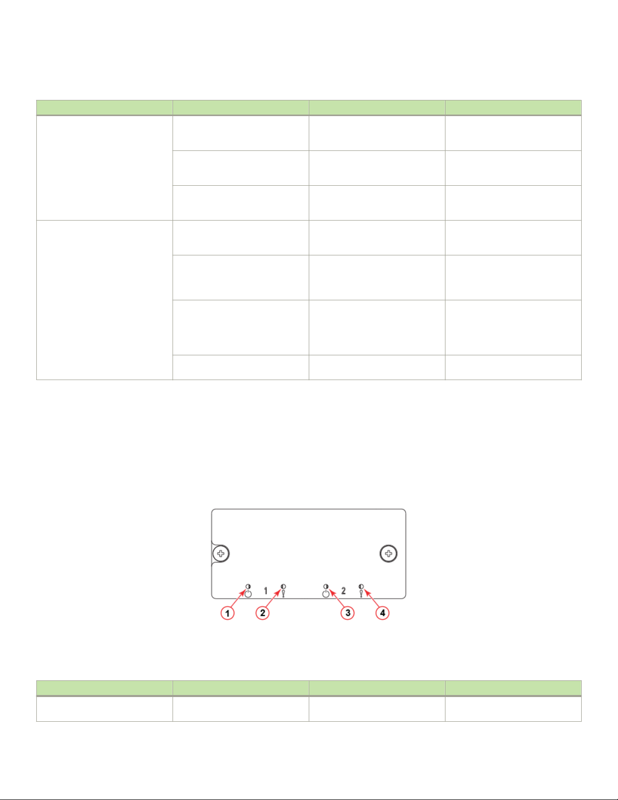
Interpreting WWN card LEDs
TABLE 15 Core routing blade LED descriptions (continued)
LED purpose Color Status Recommended action
completed booting. If the LED
remains amber, consult the supplier
for your Brocade device.
Slow-ashing amber (on 2
seconds, then o 2 seconds)
Fast-ashing amber (on 1/2
second, then o 1/2 second)
QSFP port status LED No light (LED is o) No QSFP module, all four QSFP
Steady amber QSFP module is in, all four ports
Blinking amber Port is disabled or faulted, FC link
Steady green QSFP module is in and all ports are
Blade is not seated correctly or is
faulty.
Environmental range exceeded. Check for out-of-bounds
ports are disabled
have no signal/no sync.
activity, segmented, loopback
mode, also during transition
between cable plug in and all four
ports online.
online.
Pull the blade out and reseat it. If
the LED continues to ash, replace
the blade.
environmental condition and correct
it.
No action needed if the QSFP is
not installed or verify that the QSFP
is fully inserted.
Ensure that the cable is properly
connected. If the LED remains
amber, consult the supplier for your
Brocade device.
Check for console messages or
wait for all four ports to come
online.
No action needed.
Interpreting WWN card LEDs
Refer to the following illustration and table to interpret the LED patterns of installed WWN cards. LEDs for WWN card 1 and WWN card
2 are located on the WWN card (logo) bezel between the power supplies on the nonport side of the device. The LED patterns may
temporarily change during POST and other diagnostic tests.
FIGURE 33 WWN card LEDs on bezel
1. Power LED for WWN card 1
2. Status LED for WWN card 1
TABLE 16 WWN card LED descriptions
LED purpose Color Status Recommended action
Power No light (LED is o) Card is not receiving power. Ensure that device power supplies
3. Power LED for WWN card 2
4. Status LED for WWN card 2
are rmly seated, power cables are
Brocade X6-8 Director Hardware Installation Guide
53-1004105-07 93
Page 94

Interpreting power supply LEDs
TABLE 16 WWN card LED descriptions (continued)
LED purpose Color Status Recommended action
connected, and that cables are
connected to power source.
Steady green Card is receiving power. No action required.
Status No light (LED is o) Card is either healthy or does not
have power.
Steady amber Card is faulty Replace card.
No action required.
Interpreting power supply LEDs
Refer to the following information to interpret the LED patterns on the power supply. The LED patterns may temporarily change during
POST and other diagnostic tests. The Brocade X6-8 Director can have up to four power supplies.
FIGURE 34 AC Power supply LED
1. Power status LED
FIGURE 35 HVAC/HVDC power supply LED
1. Power status LED
94 53-1004105-07
Brocade X6-8 Director Hardware Installation Guide
Page 95

Interpreting power supply LEDs
The following tables describe the power supply LED patterns and the recommended actions for those patterns. In the unlikely event of a
faulty power supply, the status LED will ash in a coded pattern to provide additional fault information. Record the sequence of ashes
and status as dened in the table to provide to your support representative along with supportsave output data.
TABLE 17 AC Power supply LED descriptions
LED purpose Color Status Recommended action
Power status No light (LED is o) Power supply does not have
incoming power and is not
providing power to the device.
NOTE
When incoming power
is rst removed, LED
ashes, and then turns
o.
Steady green Power supply has incoming power
and is providing power to the
device.
Flashing on one-half second and
then o one-half second.
Flashing on two times, and then o
5 seconds.
Flashing on three times, and then
o 5 seconds.
Flashing on four times, and then o
5 seconds.
Flashing on ve times, and then o
5 seconds.
Flashing on six times, and then o
5 seconds.
Flashing on seven times, and then
o 5 seconds.
AC power is disconnected from the
power supply assembly, but
additional power supply installed in
device is powered on.
48V is out of range. Disconnect power cable from
12V is out of range. Disconnect power cable from
AC input is under voltage. Verify voltage in power distribution
Power supply assembly fan is
faulty.
Over temperature protection. Check for blocked air ow or high
Power supply is disabled. Disconnect power cable from
Ensure that the power supply is
rmly seated, power cable is
connected, and that power cable is
connected to power source.
Disconnect power cable from
power supply, remove and reinsert
power supply, and then reconnect
power cable to restart.
If status persists, replace power
supply assembly.
No action required.
Check power connection at power
supply, cable, and AC power
source. If these check out,
disconnect power cable from power
supply, remove and reinsert power
supply, and then reconnect power
cable to restart. If status persists,
replace power supply assembly.
power supply, remove and reinsert
power supply, and then reconnect
power cable to restart. If status
persists, replace power supply
assembly. If status persists, replace
power supply.
power supply, remove and reinsert
power supply, and then reconnect
power cable to restart. If status
persists, replace power supply
assembly.
unit (PDU) or system providing
power to power supply assembly.
Check cabling and voltage between
PDU and switch. Correct the
voltage as necessary. If correct
voltage is veried, replace power
supply assembly.
Replace power supply.
ambient temperature at power
supply. If status persists, replace
power supply.
power supply, remove and reinsert
Brocade X6-8 Director Hardware Installation Guide
53-1004105-07 95
Page 96

Interpreting fan assembly LEDs
TABLE 17 AC Power supply LED descriptions (continued)
LED purpose Color Status Recommended action
power supply, and then reconnect
power cable to restart. If status
persists, replace power supply
assembly. If status persists, replace
power supply.
TABLE 18 HVAC/HVDC Power supply LED descriptions
LED purpose Color Status Recommended action
Power status No light (LED is o) Power supply does not have
incoming power and is not
providing power to the device.
NOTE
When incoming power
is rst removed, LED
ashes, and then turns
o.
Steady green Power supply has incoming power
and is providing power to the
device.
Flashing on one-half second and
then o one-half second.
Source power is disconnected from
the power supply assembly, but
additional power supply installed in
device is powered on.
Ensure that the power supply is
rmly seated, power cable is
connected, and that power cable is
connected to power source.
Disconnect power cable from
power supply, remove and reinsert
power supply, and then reconnect
power cable to restart.
If status persists, replace power
supply assembly.
No action required.
Check power connection at power
supply, cable, and power source. If
these check out, disconnect power
cable from power supply, remove
and reinsert power supply, and then
reconnect power cable to restart. If
status persists, replace power
supply assembly.
NOTE
If airow direction for a power supply assembly does not match the chassis airow direction as stored on WWN cards, the
power supply will have a "fault" status. However, LED operation for the power supply will not indicate a fault.
Interpreting fan assembly LEDs
Refer to the following illustration and table to interpret the LED patterns on fan assemblies. The LED patterns may temporarily change
during POST and other diagnostic tests. The Brocade X6-8 Director has three fan assemblies.
96 53-1004105-07
Brocade X6-8 Director Hardware Installation Guide
Page 97

FIGURE 36 Fan assembly LEDs
Interpreting fan assembly LEDs
1. Power LED 2. Status LED
TABLE 19 Fan assembly LED descriptions
LED purpose Color Status Recommended action
Power No light (LED is o) Fan assembly does not have power. Ensure that the fan assembly is
rmly seated and has power.
Steady green Fan assembly has power. No action required.
Status No light (LED is o) Fan assembly is either healthy or
does not have power.
Steady amber Fan assembly is being initialized or
has a failure (full or partial).
Slow-ashing amber (on 2
seconds, then o 2 seconds)
Brocade X6-8 Director Hardware Installation Guide
53-1004105-07 97
Fan assembly is not seated
correctly or is faulty.
Ensure that the fan assembly has
power.
Wait to see if fan fully initializes. If
LED remains amber, replace the fan
assembly.
Pull the unit out and reseat it. If the
LED continues to ash, replace the
unit.
Page 98

Interpreting POST and boot results
TABLE 19 Fan assembly LED descriptions (continued)
LED purpose Color Status Recommended action
Flashing amber (on ½ second, then
o 3.5 seconds)
Fast-ashing amber (on ½ second,
then o ½ second)
CAUTION
If fan assembly LED operation indicates a fault or no power, verify that fan is fully seated in the chassis and that captive
screws securing fan in the chassis are fully tightened. If screws are loose, pressure from fans may unseat the fan from
chassis connectors.
Fan is disabled. Run the fanEnable command to
enable the fan.
Environmental range exceeded. Check for out-of-bounds
environmental condition, resolve
any problems, and reseat the unit. If
the LED continues to ash, replace
the unit.
Interpreting POST and boot results
The device performs Power-On Self-Test (POST) by default each time the device is powered on, rebooted, or reset. The device can be
rebooted using the reboot to reboot each CP individually) or fastBoot commands. The fastBoot command reboots the switches without
running POST. If the active CP blade is rebooted, it fails over to the standby CP blade.
POST
The device automatically performs POST each time it is powered on or reset.
To verify that POST has completed without error, do the following:
• Verify that all LEDs return to a normal state after POST completes.
If one or more LEDs do not return to a normal state, and this is not due to the device being set to beacon, refer to the relevant
LED table to identify and correct the problem. For port blades, and CP and core switch blades, the slotShow command can be
used to check the status of the slots. For information about turning beaconing on or o, refer to the Brocade Fabric OS
Administration Guide.
• Verify that the switch prompt displays when POST completes.
If it does not display, POST was not successfully completed. Contact the device supplier for support.
• Review the system error log using the errShow or errDump commands.
Any errors detected during POST are written to the system log, which is accessible through the errShow command. For
information about error messages, refer to the Brocade Fabric OS Message Reference.
POST includes the following steps:
1. Preliminary POST diagnostics are run.
2. Operating system is initialized.
3. Hardware is initialized.
4. Diagnostic tests are run on several functions, including circuitry, port functionality, ability to send and receive frames, all aspects
of memory, parity, statistics counters, and serialization.
98 53-1004105-07
Brocade X6-8 Director Hardware Installation Guide
Page 99

Using monitoring commands
Boot
In addition to POST, boot includes the following steps after POST is complete:
1. Universal port conguration is performed.
2. Links are initialized.
3. Fabric is analyzed. If any ports are connected to other switches, the device participates in a fabric conguration.
4. The device obtains a domain ID and assigns port addresses.
5. Unicast routing tables are constructed.
6. Normal port operation is enabled.
Using monitoring commands
This section provides example output and explanation for commands referenced in this guide for monitoring and verifying operation of
the director and various components, such as blades, power supply assemblies, and fan assemblies.
Output for the following commands is provided:
• switchShow
• chassisShow
• haShow
• tempShow
• psShow
• sensorShow
• sfpShow
• fanShow
• errDump
• HistoryShow
• SupportSave
For more detail on using these commands, refer to the Brocade Fabric OS Command Reference. For more information on error
messages, refer to the Brocade Fabric OS Message Reference .
chassisShow
The chassisShow can be especially helpful in monitoring the health of the device. This command provides information on installed blade,
fan assembly, and power supply assembly FRUs. In addition, customer-supplied information can also be viewed, if included, for each
FRU type. Four measurements to note are:
• Power Consume Factor: Maximum power allocated for a given FRU. Except for power supply assemblies, all power is shown as
a negative number.
• Power Usage: If shown, this
• Time Awake: Time that the system as been powered on since the last reboot.
• Time Alive: Reects the total power-on time for the FRU (when available).
The following examples show output from this command.
Brocade X6-8 Director Hardware Installation Guide
53-1004105-07 99
reects real-time power usage for the FRU.
Page 100

Using monitoring commands
NOTE
The output has been truncated to reduce duplicate information.
chassisX6-8:admin> chassisshow
Chassis Family: X6-8
Chassis Backplane Revision: 0
SW BLADE Slot: 3
Header Version: 2
Power Consume Factor: -245W
Power Usage: -152W
Factory Part Num: 60-1003325-01
Factory Serial Num: DYJ0339L029
Manufacture: Day: 6 Month: 11 Year: 2015
Update: Day: 15 Month: 2 Year: 2016
Time Alive: 26 days
Time Awake: 0 days
ID:
SW BLADE Slot: 4
Header Version: 2
Power Consume Factor: -245W
Power Usage: -157W
Factory Part Num: 60-1003325-01
Factory Serial Num: DYJ0339L014
Manufacture: Day: 3 Month: 10 Year: 2015
Update: Day: 15 Month: 3 Year: 2016
Time Alive: 80 days
Time Awake: 0 days
ID:
CP BLADE Slot: 1
Header Version: 2
Power Consume Factor: -50W
Power Usage: -47W
Factory Part Num: 60-1003201-09
Factory Serial Num: DYK0338L008
Manufacture: Day: 7 Month: 10 Year: 2015
Update: Day: 23 Month: 3 Year: 2016
Time Alive: 84 days
Time Awake: 0 days
ID:
CP BLADE Slot: 2
Header Version: 2
Power Consume Factor: -50W
Power Usage: -41W
Factory Part Num: 60-1003201-09
Factory Serial Num: DYK0338L00E
Manufacture: Day: 7 Month: 10 Year: 2015
Update: Day: 23 Month: 3 Year: 2016
Time Alive: 87 days
Time Awake: 0 days
ID:
SW BLADE Slot: 5
Header Version: 2
Power Consume Factor: -420W
Power Usage: -264W
Factory Part Num: 60-1003373-01
Factory Serial Num: EAL0339L009
Manufacture: Day: 24 Month: 10 Year: 2015
Update: Day: 12 Month: 3 Year: 2016
Time Alive: 66 days
Time Awake: 0 days
ID:
SW BLADE Slot: 6
Header Version: 2
Power Consume Factor: -420W
100 53-1004105-07
Brocade X6-8 Director Hardware Installation Guide
 Loading...