

Brocade Communications Systems VDX 6940 Series, VDX 6940-36Q, VDX 6940-144S Hardware Installation Manual
Page 1

HARDWARE INSTALLATION GUIDE
Brocade VDX 6940
Hardware Installation Guide
53-1003495-06
1 June 2016
Page 2

©
2016, Brocade Communications Systems, Inc. All Rights Reserved.
Brocade, Brocade Assurance, the B-wing symbol, ClearLink, DCX, Fabric OS, HyperEdge, ICX, MLX, MyBrocade, OpenScript, VCS, VDX, Vplane, and
Vyatta are registered trademarks, and Fabric Vision is a trademark of Brocade Communications Systems, Inc., in the United States and/or in other
countries. Other brands, products, or service names mentioned may be trademarks of others.
Notice: This document is for informational purposes only and does not set forth any warranty, expressed or implied, concerning any equipment,
equipment feature, or service offered or to be offered by Brocade. Brocade reserves the right to make changes to this document at any time, without
notice, and assumes no responsibility for its use. This informational document describes features that may not be currently available. Contact a Brocade
sales office for information on feature and product availability. Export of technical data contained in this document may require an export license from the
United States government.
The authors and Brocade Communications Systems, Inc. assume no liability or responsibility to any person or entity with respect to the accuracy of this
document or any loss, cost, liability, or damages arising from the information contained herein or the computer programs that accompany it.
The product described by this document may contain open source software covered by the GNU General Public License or other open source license
agreements. To find out which open source software is included in Brocade products, view the licensing terms applicable to the open source software, and
obtain a copy of the programming source code, please visit http://www.brocade.com/support/oscd.
2 53-1003495-06
Brocade VDX 6940 Hardware Installation Guide
Page 3

Contents
Preface...........................................................................................................................................................................................................................................................................................7
Document conventions..............................................................................................................................................................................................................................................7
Text formatting conventions..........................................................................................................................................................................................................................7
Command syntax conventions....................................................................................................................................................................................................................7
Notes, cautions, and warnings.....................................................................................................................................................................................................................8
Brocade resources.......................................................................................................................................................................................................................................................8
Contacting Brocade Technical Support...........................................................................................................................................................................................................8
Brocade customers...........................................................................................................................................................................................................................................8
Brocade OEM customers..............................................................................................................................................................................................................................9
Document feedback....................................................................................................................................................................................................................................................9
About This Document.......................................................................................................................................................................................................................................................... 11
Supported hardware and software...................................................................................................................................................................................................................... 11
Fan assemblies and power supplies........................................................................................................................................................................................................11
Rack mount kits..................................................................................................................................................................................................................................................12
What's new in this document................................................................................................................................................................................................................................12
Device Overview....................................................................................................................................................................................................................................................................13
Hardware features.......................................................................................................................................................................................................................................................13
4x10 GbE breakout mode support..........................................................................................................................................................................................................14
Brocade trunking support.............................................................................................................................................................................................................................14
Dual personality ports.....................................................................................................................................................................................................................................16
Supported transceivers...................................................................................................................................................................................................................................17
License support..................................................................................................................................................................................................................................................18
Hardware components.............................................................................................................................................................................................................................................18
Port-side view................................................................................................................................................................................................................................................... 20
Non-port-side views......................................................................................................................................................................................................................................22
Port numbering.................................................................................................................................................................................................................................................26
Dual personality ports and port groups...............................................................................................................................................................................................27
Preparing for Installation..................................................................................................................................................................................................................................................29
Installation and safety considerations............................................................................................................................................................................................................ 29
Power precautions.......................................................................................................................................................................................................................................... 29
Environmental precautions........................................................................................................................................................................................................................30
EIA rack considerations................................................................................................................................................................................................................................. 31
Recommendations for cable management....................................................................................................................................................................................... 31
Items required for the installation.......................................................................................................................................................................................................................31
Items included with the device...........................................................................................................................................................................................................................32
Mounting the device...........................................................................................................................................................................................................................................................33
Mounting options.......................................................................................................................................................................................................................................................33
Mounting precautions............................................................................................................................................................................................................................................. 33
Standalone installation ...........................................................................................................................................................................................................................................34
Installing the Universal Four-Post Rack Kit (XBR-R000296)....................................................................................................................................................... 34
Installation requirements............................................................................................................................................................................................................................. 34
Time and items required............................................................................................................................................................................................................................. 35
Flush-front mounting.....................................................................................................................................................................................................................................37
Flush-rear (recessed) mounting..............................................................................................................................................................................................................42
Brocade VDX 6940 Hardware Installation Guide
53-1003495-06 3
Page 4

Installing the Universal Two-Post Rack kit (XBR-R000294)......................................................................................................................................................... 48
Installation requirements............................................................................................................................................................................................................................. 48
Time and items required............................................................................................................................................................................................................................. 49
Flush-front mounting....................................................................................................................................................................................................................................49
Mid-mounting....................................................................................................................................................................................................................................................53
Initial Configuration.............................................................................................................................................................................................................................................................59
Configuration overview...........................................................................................................................................................................................................................................59
Items required............................................................................................................................................................................................................................................................. 60
Providing power to the device........................................................................................................................................................................................................................... 60
Connecting an AC power cord................................................................................................................................................................................................................ 60
Connecting a power cord to a 500W DC power supply..........................................................................................................................................................60
Connecting a power cord to a 1100W DC power supply.......................................................................................................................................................... 62
Grounding the device using two-hole ground lug........................................................................................................................................................................63
Verifying operation....................................................................................................................................................................................................................................................65
Establishing a serial connection........................................................................................................................................................................................................................ 66
Assigning permanent passwords ....................................................................................................................................................................................................................66
Changing the default account passwords .........................................................................................................................................................................................67
Configuring the device IP address................................................................................................................................................................................................................... 67
Using DHCP to set the IP address........................................................................................................................................................................................................ 67
Setting a static IP address...........................................................................................................................................................................................................................67
Stateless IPv6 autoconfiguration............................................................................................................................................................................................................68
Setting stateless IPv6 autoconfiguration........................................................................................................................................................................................... 68
Changing the RBridge ID......................................................................................................................................................................................................................................69
Changing the VCS ID..............................................................................................................................................................................................................................................69
Setting the date and time .....................................................................................................................................................................................................................................70
Time zones..........................................................................................................................................................................................................................................................70
Time synchronization.................................................................................................................................................................................................................................... 70
Synchronizing local time using NTP.................................................................................................................................................................................................... 70
Setting the clock (date and time) manually..........................................................................................................................................................................................71
Setting the time zone.......................................................................................................................................................................................................................................71
Network device connections................................................................................................................................................................................................................................. 71
Ethernet or Fast Ethernet hubs................................................................................................................................................................................................................72
Workstations, servers, or routers.............................................................................................................................................................................................................72
Network device..................................................................................................................................................................................................................................................72
Testing connectivity.........................................................................................................................................................................................................................................72
Operation.................................................................................................................................................................................................................................................................................. 73
Interpreting LED activity.........................................................................................................................................................................................................................................73
LED locations.....................................................................................................................................................................................................................................................73
Port-side LED patterns.................................................................................................................................................................................................................................76
Non-port-side LED patterns for VDX 6940-36Q......................................................................................................................................................................78
Non-port-side LED patterns for VDX 6940-144S......................................................................................................................................................................79
POST and boot specifications...........................................................................................................................................................................................................................80
POST..................................................................................................................................................................................................................................................................... 80
Boot........................................................................................................................................................................................................................................................................ 80
Interpreting POST results.......................................................................................................................................................................................................................................81
Diagnostic tests............................................................................................................................................................................................................................................................81
Device management................................................................................................................................................................................................................................................. 81
Powering off the device......................................................................................................................................................................................................................................... 82
Thermal operations.................................................................................................................................................................................................................................................. 82
4 53-1003495-06
Brocade VDX 6940 Hardware Installation Guide
Page 5

Removal and Replacement Procedures................................................................................................................................................................................................................ 83
Before beginning replacement .........................................................................................................................................................................................................................83
ESD precautions........................................................................................................................................................................................................................................................ 84
VDX 6940-36Q FRU replacement...............................................................................................................................................................................................................85
Determining the need to replace a power supply.........................................................................................................................................................................85
Time and items required to replace a power supply...................................................................................................................................................................85
Power supply replacement........................................................................................................................................................................................................................ 85
Determining the need to replace a fan assembly.........................................................................................................................................................................90
Time and items required to replace a fan assembly.....................................................................................................................................................................91
Replacing a fan assembly.............................................................................................................................................................................................................................91
VDX 6940-144S FRU replacement...............................................................................................................................................................................................................92
Determining the need to replace a power supply.........................................................................................................................................................................93
Time and items required to replace a power supply...................................................................................................................................................................93
Power supply replacement........................................................................................................................................................................................................................ 93
Determining the need to replace a fan assembly......................................................................................................................................................................... 99
Time and items required to replace a fan assembly................................................................................................................................................................... 99
Replacing a fan assembly...........................................................................................................................................................................................................................99
QSFP transceiver removal and replacement............................................................................................................................................................................................ 101
Removing a QSFP transceiver..............................................................................................................................................................................................................102
Replacing a QSFP transceiver...............................................................................................................................................................................................................102
SFP transceiver removal and replacement...............................................................................................................................................................................................102
Time and items required............................................................................................................................................................................................................................103
Removing a transceiver..............................................................................................................................................................................................................................103
Replacing a transceiver...............................................................................................................................................................................................................................104
Brocade VDX 6940 Switch Technical Specifications...................................................................................................................................................................................105
System specifications............................................................................................................................................................................................................................................105
Ethernet......................................................................................................................................................................................................................................................................... 105
LEDs................................................................................................................................................................................................................................................................................105
Other............................................................................................................................................................................................................................................................................... 106
Weight and physical dimensions.................................................................................................................................................................................................................... 106
Environmental requirements.............................................................................................................................................................................................................................106
Power supply specifications (per PSU)........................................................................................................................................................................................................107
Power consumption (typical configuration)...............................................................................................................................................................................................108
Power consumption (idle configuration).....................................................................................................................................................................................................109
Power consumption (maximum configuration)...................................................................................................................................................................................... 109
Data port specifications (Ethernet).................................................................................................................................................................................................................109
Serial port specifications (pinout RJ-45)......................................................................................................................................................................................................110
Serial port specifications (protocol)..................................................................................................................................................................................................................110
Memory specifications............................................................................................................................................................................................................................................110
Regulatory compliance (EMC)..............................................................................................................................................................................................................................111
Regulatory compliance (safety)............................................................................................................................................................................................................................111
Regulatory compliance (environmental).........................................................................................................................................................................................................111
Regulatory Statements..................................................................................................................................................................................................................................................... 113
BSMI statement (Taiwan).......................................................................................................................................................................................................................................113
Canadian requirements...........................................................................................................................................................................................................................................113
CE statement................................................................................................................................................................................................................................................................113
China ROHS................................................................................................................................................................................................................................................................. 114
FCC warning (US only)........................................................................................................................................................................................................................................... 114
KCC statement (Republic of Korea).................................................................................................................................................................................................................114
Brocade VDX 6940 Hardware Installation Guide
53-1003495-06 5
Page 6

VCCI statement...........................................................................................................................................................................................................................................................114
Germany statement..................................................................................................................................................................................................................................................114
Cautions and Danger Notices.......................................................................................................................................................................................................................................115
Cautions...........................................................................................................................................................................................................................................................................115
General cautions...............................................................................................................................................................................................................................................115
Electrical cautions............................................................................................................................................................................................................................................ 118
Danger notices.............................................................................................................................................................................................................................................................121
General dangers................................................................................................................................................................................................................................................121
Laser dangers...................................................................................................................................................................................................................................................122
Electrical dangers...........................................................................................................................................................................................................................................122
Dangers related to equipment weight................................................................................................................................................................................................123
6 53-1003495-06
Brocade VDX 6940 Hardware Installation Guide
Page 7

Preface
∙ Document conventions..................................................................................................................................................................................................... 7
∙ Brocade resources...............................................................................................................................................................................................................8
∙ Contacting Brocade Technical Support...................................................................................................................................................................8
∙ Document feedback........................................................................................................................................................................................................... 9
Document conventions
The document conventions describe text formatting conventions, command syntax conventions, and important notice formats used in
Brocade technical documentation.
Text formatting conventions
Text formatting conventions such as boldface, italic, or Courier font may be used in the flow of the text to highlight specific words or
phrases.
Format Description
bold text Identifies command names
Identifies keywords and operands
Identifies the names of user-manipulated GUI elements
Identifies text to enter at the GUI
italic
text Identifies emphasis
Identifies variables
Identifies document titles
Courier font
Identifies CLI output
Identifies command syntax examples
Command syntax conventions
Bold and italic text identify command syntax components. Delimiters and operators define groupings of parameters and their logical
relationships.
Convention Description
bold text Identifies command names, keywords, and command options.
italic
text Identifies a variable.
value In Fibre Channel products, a fixed value provided as input to a command option is printed in plain text, for
example, --show WWN.
[ ] Syntax components displayed within square brackets are optional.
Default responses to system prompts are enclosed in square brackets.
{ x | y | z } A choice of required parameters is enclosed in curly brackets separated by vertical bars. You must select
one of the options.
In Fibre Channel products, square brackets may be used instead for this purpose.
x | y A vertical bar separates mutually exclusive elements.
< > Nonprinting characters, for example, passwords, are enclosed in angle brackets.
Brocade VDX 6940 Hardware Installation Guide
53-1003495-06 7
Page 8

Preface
Convention Description
... Repeat the previous element, for example,
\ Indicates a “soft” line break in command examples. If a backslash separates two lines of a command
input, enter the entire command at the prompt without the backslash.
member[member
...].
Notes, cautions, and warnings
Notes, cautions, and warning statements may be used in this document. They are listed in the order of increasing severity of potential
hazards.
NOTE
A Note provides a tip, guidance, or advice, emphasizes important information, or provides a reference to related information.
ATTENTION
An Attention statement indicates a stronger note, for example, to alert you when traffic might be interrupted or the device might
reboot.
CAUTION
A Caution statement alerts you to situations that can be potentially hazardous to you or cause damage to hardware, firmware,
software, or data.
DANGER
A Danger statement indicates conditions or situations that can be potentially lethal or extremely hazardous to you. Safety labels
are also attached directly to products to warn of these conditions or situations.
Brocade resources
Visit the Brocade website to locate related documentation for your product and additional Brocade resources.
You can download additional publications supporting your product at www.brocade.com. Select the Brocade Products tab to locate your
product, then click the Brocade product name or image to open the individual product page. The user manuals are available in the
resources module at the bottom of the page under the Documentation category.
To get up-to-the-minute information on Brocade products and resources, go to MyBrocade. You can register at no cost to obtain a user
ID and password.
Release notes are available on MyBrocade under Product Downloads.
White papers, online demonstrations, and data sheets are available through the Brocade website.
Contacting Brocade Technical Support
As a Brocade customer, you can contact Brocade Technical Support 24x7 online, by telephone, or by e-mail. Brocade OEM customers
contact their OEM/Solutions provider.
Brocade customers
For product support information and the latest information on contacting the Technical Assistance Center, go to http://
www.brocade.com/services-support/index.html.
If you have purchased Brocade product support directly from Brocade, use one of the following methods to contact the Brocade
Technical Assistance Center 24x7.
8 53-1003495-06
Brocade VDX 6940 Hardware Installation Guide
Page 9

Preface
Online Telephone E-mail
Preferred method of contact for non-urgent
issues:
∙ My Cases through MyBrocade
∙ Software downloads and licensing
tools
∙ Knowledge Base
Required for Sev 1-Critical and Sev 2-High
issues:
∙ Continental US: 1-800-752-8061
∙ Europe, Middle East, Africa, and Asia
Pacific: +800-AT FIBREE (+800 28
34 27 33)
∙ For areas unable to access toll free
number: +1-408-333-6061
∙ Toll-free numbers are available in
many countries.
support@brocade.com
Please include:
∙ Problem summary
∙ Serial number
∙ Installation details
∙ Environment description
Brocade OEM customers
If you have purchased Brocade product support from a Brocade OEM/Solution Provider, contact your OEM/Solution Provider for all of
your product support needs.
∙ OEM/Solution Providers are trained and certified by Brocade to support Brocade® products.
∙ Brocade provides backline support for issues that cannot be resolved by the OEM/Solution Provider.
∙ Brocade Supplemental Support augments your existing OEM support contract, providing direct access to Brocade expertise.
For more information, contact Brocade or your OEM.
∙ For questions regarding service levels and response times, contact your OEM/Solution Provider.
Document feedback
To send feedback and report errors in the documentation you can use the feedback form posted with the document or you can e-mail
the documentation team.
Quality is our first concern at Brocade and we have made every effort to ensure the accuracy and completeness of this document.
However, if you find an error or an omission, or you think that a topic needs further development, we want to hear from you. You can
provide feedback in two ways:
∙ Through the online feedback form in the HTML documents posted on www.brocade.com.
∙ By sending your feedback to documentation@brocade.com.
Provide the publication title, part number, and as much detail as possible, including the topic heading and page number if applicable, as
well as your suggestions for improvement.
Brocade VDX 6940 Hardware Installation Guide
53-1003495-06 9
Page 10

Preface
10 53-1003495-06
Brocade VDX 6940 Hardware Installation Guide
Page 11
About This Document
∙ Supported hardware and software..............................................................................................................................................................................11
∙ What's new in this document........................................................................................................................................................................................12
Supported hardware and software
This document is applicable to the following devices and operating systems.
Device First supported OS
Brocade VDX 6940-36Q Network OS v6.0.0
Brocade VDX 6940-144S Network OS v6.0.1
The following tables provide information on supported Field Replaceable Units (FRUs).
Fan assemblies and power supplies
The following tables provide information on supported fan assemblies and power supplies.
TABLE 1 Fan assemblies
Part number Short description Where used First supported (OS) Last supported (OS)
Fan assemblies
XBR-FAN-40-F 40 MM nonport side
exhaust fan
XBR-FAN-40-R 40 MM port-side exhaust
fan
XBR-FAN-80-01-F 80 MM nonport side
exhaust fan
XBR-FAN-80-01-R 80 MM port side exhaust
fan
Brocade VDX 6940-36Q Network OS 6.0.0 Active
Brocade VDX 6940-36Q Network OS 6.0.0 Active
Brocade VDX 6940-144S Network OS 6.0.1 Active
Brocade VDX 6940-144S Network OS 6.0.1 Active
TABLE 2 Power supplies
Part number Short description Where used First supported (OS) Last supported (OS)
XBR-500WPSAC-01-R AC 500W power supply,
port side exhaust
XBR-500WPSAC-01-F AC 500W power supply,
nonport side exhaust
RPS9DC DC 500W power supply,
exhaust
RPS9DC+1 DC 500W power supply,
intake
XBR-1100WPSAC-F AC 1100W power supply,
nonport side exhaust
XBR-1100WPSAC-R AC 1100W power supply,
port side exhaust
Brocade VDX 6940 Hardware Installation Guide
53-1003495-06 11
Brocade VDX 6940-36Q,
Brocade VDX 6740T
Brocade VDX 6940-36Q,
Brocade VDX 6740T
Brocade VDX 6940-36Q Network OS 6.0.0 Active
Brocade VDX 6940-36Q Network OS 6.0.0 Active
Brocade VDX 6940-144S Network OS 6.0.1 Active
Brocade VDX 6940-144S Network OS 6.0.1 Active
Network OS 6.0.0 Active
Network OS 6.0.0 Active
Page 12

About This Document
TABLE 2 Power supplies (continued)
Part number Short description Where used First supported (OS) Last supported (OS)
XBR-1100WPSDC-01-F DC 1100W power supply,
nonport side exhaust
XBR-1100WPSDC-01-R DC 1100W power supply,
port side exhaust
Brocade VDX 6940-144S Network OS 6.0.1 Active
Brocade VDX 6940-144S Network OS 6.0.1 Active
Rack mount kits
The following table provides information on supported rack mount kits.
TABLE 3 Rack mount kits
Part number Short description Device where used First supported (OS) Last supported (OS)
XBR-R000296 Universal four-post rack kit Brocade VDX 6940-144S
and Brocade VDX
6940-36Q
XBR-R000294 Universal two-post rack kit Brocade VDX 6940-144S
and Brocade VDX
6940-36Q
N/A Active
N/A Active
What's new in this document
This document has been updated to include the following new information:
∙ Added Preparing for Installation on page 29 section.
∙ Removed "Product Installation" section.
∙ Added Mounting the device on page 33 section containing procedures for installing all rack mount kits associated with this
device.
∙ Moved "Providing power to the device" and "Verifying operation" to "Initial Configuration."
∙ Modified note in Establishing a serial connection on page 66 about flow control support.
∙ Added Items required on page 60 to "Initial Configuration."
∙ Modified signal and description for pins 3 and 6 in "Serial port specifications (pinout RJ-45)" in Brocade VDX 6940 Switch
Technical Specifications on page 105.
∙ Updated Regulatory Statements on page 113.
12 53-1003495-06
Brocade VDX 6940 Hardware Installation Guide
Page 13

Device Overview
∙ Hardware features.............................................................................................................................................................................................................. 13
∙ Hardware components.................................................................................................................................................................................................... 18
Hardware features
There are two VDX 6940 models provide unique port configurations and hardware features that allow them to function in a spine and
leaf architecture.
∙ The Brocade VDX 6940-36Q provides up to 36 40 GbE quad small form-factor pluggable (QSFP) ports for connecting
devices in a data center fabric. The base model of this 1U form-factor device contains twenty-four 40 GbE ports. A single 40G
Port Upgrade license can add 12 additional ports to provide the full complement of 36 40 GbE ports. Each 40 GbE port can be
reconfigured as four 10 GbE ports in QSFP breakout mode to provide a total of 144 10 GbE ports for the device.
∙ The Brocade VDX 6940-144S provides up to 12 40 GbE QSFP ports and 96 fixed 10 GbE ports for connecting devices in a
data center fabric. The 10 GbE ports support SFP+ and TSFP+ optics. Each 40 GbE port can be reconfigured as four 10 GbE
ports in QSFP breakout mode to provide a total of 144 10 GbE ports for the device. Using the dual-personality port feature,
dual-personality 40/100 GbE ports can be reconfigured to provide the following port combinations:
– 12 40 GbE QSFP ports and no 100 GbE QSFP28 port
– 9 40 GbE QSFP ports and 1 100 GbE QSFP28 port
– 6 40 GbE QSFP ports and 2 100 GbE QSFP28 ports
– 3 40 GbE QSFP ports and 3 100 GbE QSFP28 ports
– No 40 GbE QSFP ports and 4 100 GbE QSFP28 ports
The base model of this 2U form-factor device contains 64 fixed 10 GbE base ports and no 40 GbE ports. Two 10G Port
Upgrade licenses can provide the full complement of 96 fixed 10 GbE ports in two 16-port increments. Two 40G Port Upgrade
licenses provide up to 12 40 GbE ports in two six-port increments. To configure a dual personality port for 100 GbE operation,
all three ports in the dual-personality port group must have ports on demand (POD) reservations allocated from a 40 GbE Port
Upgrade license.
∙ Multiple fan and power supply field replaceable units (FRUs) in these devices allow redundant operation in the event of FRU
failure.
∙ A key feature of the Brocade VDX 6940 is Brocade VCS™ technology, which includes virtual cluster switching, a set of
technologies that allows users to create flatter, virtualized, and converged data center networks. VCS fabrics are scalable,
permitting users to expand at their own pace, and simplified, allowing users to manage the fabric as a single entity. VCS-based
Ethernet fabrics are convergence-capable with technologies such as Fibre Channel over Ethernet (FCoE) for storage. For full
details and configuration procedures for VCS fabrics, refer to the
∙ The Brocade VDX 6940 can also be deployed in IP fabrics. An IP fabric can be described as a collection of discrete Layer 3
elements (such as switch-routers) arranged in a spine-leaf network. These elements exchange Layer 2 and Layer 3 database
information to provide a flexible, nonblocking and scalable framework while retaining the semantics of a single logical switch.
There can be competing protocols for exchanging this distributed database across such discrete elements. Spine-leaf networks
are designed to be a three-stage architecture, an ingress stage, a middle stage, and an egress stage. The concept is that there
are multiple paths for the call to be switched through the network so that traffic can always connect and not be blocked. For full
details and configuration procedures for IP fabrics, refer to the
Network OS Administration Guide
Network OS IP Fabrics Configuration Guide
.
.
Brocade VDX 6940 Hardware Installation Guide
53-1003495-06 13
Page 14

Device Overview
4x10 GbE breakout mode support
Each 40 GbE port on the Brocade VDX 6940 can be configured for breakout mode to provide four 10 GbE interfaces. You can
administer and operate the 10 GbE interfaces as any other SFP port.
Optical and twinaxial copper 4x10 GbE QSFP breakout cables provide a connection from the 40 GbE port to four 10 GbE SFP ports on
other devices. The 10 GbE breakout connections are primarily used for edge port connectivity, but can also support ISL trunking with
VDX 8770 and VDX 6740 platforms.
The 40 GbE ports support dynamic QSFP breakout mode as there is no need to reboot the system to enable breakout mode after
breakout mode is configured. For more information on configuring breakout mode, refer to the
Configuration Guide
NOTE
Breakout mode is not supported on Brocade VDX 6940-144S 100 GbE ports.
For a information on 4x10 GbE QSFP to 4 SFP optical and copper cable that support 4x10 GbE breakout mode, refer to the online
matrices referenced in Supported transceivers on page 17.
.
Network OS Layer 2 Switching
Brocade trunking support
Network OS supports Brocade trunks (hardware-based link aggregation groups, or LAGs). These trunks are dynamically formed
between two adjacent devices with connected interswitch link (ISL) ports unless trunking is disabled on connecting ports. Traffic is evenly
distributed along all links in a trunk.
Brocade trunking is supported on the following port types:
∙ 10 GbE ports
∙ 40 GbE ports in 40 GbE mode
∙ 10 GbE interfaces when 4x10 GbE breakout mode is configured on 40 GbE ports.
NOTE
Trunking is not supported on 100 GbE ports.
Following are general limitations and considerations of this feature:
∙ Ports forming a trunk must be configured at the same speed as follows:
– 40 GbE ports configured in 40 GbE mode - 40 Gbps
– 10 GbE interfaces on 40 GbE ports configured in 4x10 GbE breakout mode - 10 Gbps.
– 10 GbE ports - 10 Gbps
∙ Ports forming a trunk must be in the same trunk group. Trunk groups are different for the Brocade VDX 6940-36Q and
Brocade VDX 6940-144S.
∙ Any port in a trunk group can belong to a specific trunk, but ports do not need to be contiguous. For example, port 1, 2, and 7
can form a trunk with a remote device. If ports 3 and 4 are connected later, they will form a separate trunk.
∙ The maximum number of ports that can form a trunk are as follows:
– 12 fixed 10 GbE ports
– 12 10 GbE interfaces on 40 GbE ports in 4 x 10 GbE breakout mode.
– Three 40 GbE ports (40 GbE mode)
∙ Trunking is supported between Brocade VDX 6940 40 GbE ports and Brocade VDX 8770 ports only when all ports are
configured in 4x10 GbE breakout mode. Trunking is not supported between these devices when the 40 GbE ports are
configured in 40 GbE mode.
∙ 40 GbE and 10 GbE trunking is supported between Brocade Brocade VDX 6940 and Brocade VDX 6740 devices.
14 53-1003495-06
Brocade VDX 6940 Hardware Installation Guide
Page 15

Device Overview
∙ MCAST LAG spraying is not supported on trunks.
∙ Standard 802.1ag LAG and Brocade vLAG functions are supported on fixed 10 GbE ports, 40 GbE ports in 40 GbE mode, and
on 10 GbE interfaces on 40 GbE ports when in 4x10 GbE breakout mode. However, all ports in the LAG or vLAG must be
configured at the same speed, 10 GbE or 40 GbE. If the port speeds do not match, the port will not be logically online and will
fail to become a member of the LAG or vLAG.
Ports forming a trunk must be in the same trunk group. The following tables show the port numbers that belong to each trunk group for
Brocade VDX 6940 devices. Colored labels attached above and below ports on the port-side of the device designate ports that belong
to the same trunk group.
TABLE 4 Trunk groups in the Brocade VDX 6940-36Q
Trunk group Color label by port GbE port number Port speeds
TG1 Blue 1 through 9 40 Gbps - 40 GbE mode
10 Gbps - 4x10 GbE breakout mode
TG2 Yellow 10 through 18 40 Gbps - 40 GbE mode
10 Gbps - 4x10 GbE breakout mode
TG3 Purple 19 through 27 40 Gbps - 40 GbE mode
10 Gbps - 4x10 GbE breakout mode
TG4 Green 28 through 36 40 Gbps - 40 GbE mode
10 Gbps - 4x10 GbE breakout mode
TABLE 5 Trunk groups in the Brocade VDX 6940-144S
Trunk group Color label by port GbE port number Port speeds
TG-1 Blue 1 through 24
61 through 72
TG-2 Yellow 25 through 48
73 through 84
TG-3 Green 85 through 96 and 40 GbE
ports 97 through 102 if
breakout mode is
configured
TG-3A
NOTE
Ports in this
group cannot be
trunked with
TG-3 ports.
TG-4 Purple 49 through 60 and 40 GbE
TG-4A
NOTE
Ports in this
group cannot be
trunked with
TG-4 ports.
Green 103 through 108 40 Gbps - 40 GbE mode
ports 97 through 102 if
breakout mode is
configured
Purple 97 through 102 40 Gbps - 40 GbE mode
10 Gbps
10 Gbps
10 Gbps
10 Gbps
10 Gbps
10 Gbps
Brocade VDX 6940 Hardware Installation Guide
53-1003495-06 15
Page 16

Device Overview
TABLE 5 Trunk groups in the Brocade VDX 6940-144S (continued)
Trunk group Color label by port GbE port number Port speeds
TG-4A
NOTE
Ports in this
group cannot be
trunked with
TG-4 ports.
Purple 97 through 102 40 Gbps - 40 GbE mode
10 Gbps - 4x10 GbE breakout mode
NOTE
For a diagram and information on Brocade VDX 6940 device port numbering, refer to VDX 6940-36Q port numbering on
page 26.
For more information on Brocade trunking and enabling and disabling trunking, refer to the "Configuring Brocade VCS Fabrics" chapter
in the
Network OS Administration Guide
.
Dual personality ports
The dual personality port feature for the Brocade VDX 6940-144S allows ports 97, 98, 103, and 104 to be configured as 40 GbE QSFP
+ or 100 GbE QSFP28 ports provided appropriate transceivers are installed.
Four rows of 40 GbE ports are located on the right side of the Brocade VDX 6940-144S front panel with three ports per row. Each row
is assigned a dual personality group number of 1 through 4. The following table shows port group mapping to the dual personality port
and other ports in the row. Refer to Dual personality ports and port groups on page 27 for the specific location of dual personality ports
and port groups on the device.
TABLE 6 Dual personality port groups
Port Group 40/100 GbE port # (dual
personality port)
1 97 99 101
2 98 100 102
3 103 105 107
4 104 106 108
40 GbE port # 40 GbE port #
The group number is used in Network OS commands for configuration. When you configure 100 GbE mode for a port group, only the
dual personality port operates at 100 GbE, if the appropriate 100 GbE QSFP28 transceiver is installed in that port. The remaining two 40
GbE ports in the group are disabled. Conversely, if you reconfigure the port group from 100 GbE to 40 GbE operation, the dual
personality port will transition to 40 GbE mode. All three ports in the group will come back online at 40 GbE operation if appropriate 40
GbE optics transceivers installed.
The following port configurations are possible for the twelve 40 GbE ports on the device:
∙ 12 40 GbE QSFP ports and No 100 GbE QSFP28 ports
∙ 9 40 GbE QSFP ports and 1 100 GbE QSFP28 port
∙ 6 40 GbE QSFP ports and 2 100 GbE QSFP28 ports
∙ 3 40 GbE QSFP ports and 3 100 GbE QSFP28 ports
∙ No 40 GbE QSFP ports and 4 100 GbE QSFP28 ports
Ports configured for 100 GbE operation with supported 100 GbE QSFP28 media installed can connect with 100 GbE CFP2
transceivers on the Brocade VDX 8770 6x100 GbE line card port through a Brocade CFP2 to QSFP28 Conversion Module. This
16 53-1003495-06
Brocade VDX 6940 Hardware Installation Guide
Page 17

Device Overview
module plugs into the line card port cage as CFP2 transceiver and a QSFP28 transceiver is installed on the input side for connection to
Brocade VDX 6940-144S 100 GbE QSFP28 ports. The Brocade VDX 8770-8 line card and Brocade VDX 6940-144S ports connect
with optical 40 GbE QSFP to QSFP cable using MPO connectors. For more information on the Brocade CFP2 to QSFP28 Conversion
Module, refer to the
NOTE
100 GbE QSFP28 transceivers do not support breakout mode.
Brocade VDX 8770-4 or Brocade VDX 8770-8 Hardware Installation Guides
.
Configure 100 GbE operation on specific dual personality port groups using the port-group
100g
command. You can transition to 40 GbE operation for specific port groups using the port-group
mode
40g
command. To enable 100 GbE or 40 GbE operation, you must reboot the Brocade VDX 6940-144S. For details on
configuring dual personality ports and displaying port and port group configuration, refer to the
Configuration Guide
Before enabling 100 GbE mode for a port group, perform the following tasks:
∙ Disable 4x10 GbE breakout mode for all ports in that port group, if configured. Ports must be enabled for 40 GbE mode.
∙ Disable all ports in the port group.
∙ Install the appropriate 100 GbE QSFP28 transceiver in the dual-personality port cage for that port group (port 97, 98, 103, or
104).
∙ Reserve the DPOD for the ports in the port group.
.
rbridge-id/slot/port-group-id
rbridge-id/slot/port-group-id
Network OS Layer 2 Switching
and mode
Limitations and considerations
Consider the following when configuring and using dual-personality ports and port groups.
∙ When you enable 100 GbE mode for a port group, the leftmost port in the group (dual personality port 97, 98, 103, or 104) will
be enabled for 100 GbE operation and the other ports in the port group will be disabled.
∙ Ports with supported 40 GbE QSFP transceivers that are not in a dual personality port group configured for 100 GbE operation
can function in 40 GbE mode and can be configured 4x10 GbE breakout mode.
∙ To transition port 97, 98, 103, or 104 from 100 GbE to 40 GbE operation, you must install a supported 40 GbE QSFP+
transceiver in that port. You can transition a port group from 100 GbE operation to 40 GbE operation and leave the 100 GbE
QSFP128 transceiver installed in port 97, 98, 103, or 104. The other ports in the port group will operate at 40 GbE and can be
configured for 4x10 GbE breakout mode, however the 100 GbE dual personality port will be unusable unless you replace the
transceiver with a qualified 40 GbE transceiver.
∙ Any configuration applied to ports in a port group will be removed when you change to 100 GbE mode or 40 GbE mode.
∙ A specific dual personality port license is not required, but to enable a dual-personality port in a port group for 100 GbE
operation, all three ports in the port group must have ports on demand (POD) reservations allocated from a 40 GbE Port
Upgrade license. Refer to Dual personality ports and port groups on page 27 for the location of dual-personality ports and port
groups.
∙ Trunking is not supported on 100 GbE ports.
∙ 100 GbE QSFP28 SR4 optics support Forward error correction (FEC). FEC enhances data reliability by inserting redundant
data, called error correcting code, into data being transmitted or stored. FEC is enabled by default on the Brocade QSFP28
SR4 optics.
and
Supported transceivers
For details on supported transceivers, refer to the following publications on www.brocade.com:
Brocade VDX 6940 Hardware Installation Guide
53-1003495-06 17
Page 18

Device Overview
∙
Brocade VDX Transceiver Support Matrix
∙
Brocade Fibre Channel Transceiver Support Matrix
Brocade VDX 6940-144S fixed 10 GbE ports support tunable SFP+ (TSFP+) transceivers. If used, TSFP+ transceivers must be installed
in the port at each end of a link and "tuned" to the same wavelength. If not, the link may come online, but operation may be
unpredictable. If wavelength difference exceeds a specified limit, a RASLOG message occurs and the port is taken offline. You can
configure wavelengths for installed transceivers using channel numbers from 1 to 102 that correspond to wavelengths from 1568.77 to
1528.38 nm using the tunable-optics sfpp channel
the
Network OS Administration Guide
DANGER
.
.
.
channel number
command. For details on using this and related commands, refer to
All fiber-optic interfaces use Class 1 lasers.
DANGER
Use only optical transceivers that are qualified by Brocade Communications Systems, Inc. and comply with the FDA Class 1
radiation performance requirements defined in 21 CFR Subchapter I, and with IEC 825 and EN60825. Optical products that do
not comply with these standards might emit light that is hazardous to the eyes.
License support
Brocade VDX 6940-36Q supports devices the following licenses:
∙ 40 GbE Port Upgrade - Increases the number of 40 GbE ports provided in a base configuration. For the Brocade VDX
6940-36Q, a single license increases the 24 ports enabled in a base configuration to 36.
∙ FCoE Base - Enables FCoE functionality on the 10 GbE links formed when configuring 40 GbE ports in 4x10 GbE breakout
mode.
The Brocade VDX 6940-144S supports the following licenses:
∙ 40 GbE Port Upgrade - Increases the number of 40 GbE ports provided in a base configuration. For the Brocade VDX
6940-144S, each license increases the 0 ports enabled in a base configuration to 12 in two 6-port increments.
∙ 10 GbE Port Upgrade - Increases the number of fixed 10 GbE ports provided in a base configuration. For the Brocade VDX
6940-144S, each license increases the 64 ports enabled in a base configuration to 96 in two 16-port increments.
∙ FCoE Base - Enables FCoE functionality on the fixed 10 GbE ports and the 10 GbE links formed when configuring 40 GbE
ports in 4x10 GbE breakout mode.
∙ 100 GbE ports - A specific dual personality port license is not required, but to enable a dual-personality port in a port group for
100 GbE operation, all three ports in the port group must have ports on demand (POD) reservations allocated from a 40 GbE
Port Upgrade license. Refer to Dual personality ports and port groups on page 27 for the location of dual-personality ports
and port groups.
For more information on these licenses, refer to the
Network OS Software Licensing Guide
.
Hardware components
Interface ports, component status LED indicators, and field replaceable units (FRUs) are located on the port side and non-port side of
Brocade VDX 6940 devices.
The following components are on the port side of the device:
∙ A USB connector for firmware upgrades and system log downloads.
∙ A RJ-45 Ethernet management port for out-of-band management.
18 53-1003495-06
Brocade VDX 6940 Hardware Installation Guide
Page 19

Device Overview
– The Brocade VDX 6940-36Q port supports 10/100/1000 MB.
– The Brocade VDX 6940-144S port supports 1000 MB.
∙ An RJ-45 serial (RS-232) console port for terminal access and debugging.
∙ GbE ports for fabric connections:
– Brocade VDX 6940-36Q - up to 36 40 GbE QSFP ports.
– Brocade VDX 6940-144S - up to 96 fixed 10 GbE ports and 12 40 GbE QSFP ports. Using the Dual-Personality port
feature, 40 GbE ports can be reconfigured to provide the following port combinations:
› 12 40 GbE QSFP ports and no 100 GbE QSFP28 port
› 9 40 GbE QSFP ports and 1 100 GbE QSFP28 port
› 6 40 GbE QSFP ports and 2 100 GbE QSFP28 ports
› 3 40 GbE QSFP ports and 3 100 GbE QSFP28 ports
› No 40 GbE QSFP ports and 4 100 GbE QSFP28 ports
∙ For 40 GbE ports, four green LEDs are located above each upper 40 GbE port and below each lower 40 GbE port. In 40 GbE
mode, the first of the four LEDs illuminates to indicate 40 GbE status. In 4x10 GbE breakout mode, each of the four LEDs
illuminate to indicate status of individual 10 GbE lanes.
∙ When a dual-personality 40/100-GbE port is configured for 100-GbE operation (Brocade VDX 6940-144S only), the first of
the four LEDs above the port illuminates to indicate 100 GbE status.
∙ For fixed 10 GbE ports on the Brocade VDX 6940-144S) - Two triangle-shaped bicolor (green and amber) port status LEDs
are arrayed between each row of ports. One LED indicates status of the upper 10 GbE port one indicates status of the lower 10
GbE port.
∙ System power LED - Indicates system power on or off.
∙ System status LED - Indicates normal operation, internal diagnostics operation, and device fault state.
∙ Ethernet status LED - Indicates management Ethernet management port online and offline status and traffic activity.
The following components are on the non-port side of the Brocade VDX 6940-36Q:
∙ Dual, hot-swappable 500W AC or DC power supplies. Each power supply FRU contains a fan and can be ordered with front-
to-back or back-to-front airflow. Although the two power supplies provide redundancy for required power, both must be
installed to provide sufficient airflow from their fans.
∙ Five hot-swappable fan assemblies, each with two fans. These fan FRUs can be ordered with front-to-back or back-to-front
airflow.
∙ Fan status LED on each fan FRU.
∙ Power supply status LED on each power supply FRU.
The following components are on the non-port side of the Brocade VDX 6940-144S:
∙ Dual, hot-swappable 1100W AC or DC power supplies. Each power supply FRU contains a fan and can be ordered with front-
to-back or back-to-front airflow. Although the two power supplies provide redundancy for required power, both must be
installed to provide sufficient airflow from their fans.
∙ Four hot-swappable fan assemblies, each with one fan. These fan FRUs can be ordered with front-to-back or back-to-front
airflow.
∙ Fan status LED on each fan FRU.
∙ Two power supply status LEDs on each power supply FRU.
The following transceivers and QSFP cables are available for Brocade VDX 6940 GbE ports:
∙ Short-range and long-range 40 GbE QSFP+ transceivers.
∙ Short-range and long-range 10 GbE SFP+ transceivers (Brocade VDX 6940-144S).
Brocade VDX 6940 Hardware Installation Guide
53-1003495-06 19
Page 20
Device Overview
∙ Short-range and long-range 100 GbE QSFP28 transceivers (Brocade VDX 6940-144S).
∙ 4x10 GbE QSFP to 4 SFP optical or twinaxial breakout cable for 40 GbE ports when configured in 4x10 GbE breakout mode.
∙ 40 GbE QSFP to QSFP optical or twinaxial cable for connecting ports in non-breakout mode.
∙ Optical 40GbE QSFP to QSFP 10m AOC cables can be used for 100 GbE port connections on the Brocade VDX 6940-144S.
∙ 10 GbE optical and twinaxial copper cable for connecting 10 GbE ports on the Brocade VDX 6940-144S.
The Brocade VDX 6940 contains non-volatile random access memory (NVRAM) with integrated real-time clock (RTC) function.
CAUTION
Ensure that the airflow direction of the power supply unit matches that of the installed fan tray. The power supplies and fan trays
are clearly labeled with either a green arrow with an "E", or an orange arrow with an "I."
Port-side view
Use the following illustrations to locate ports, LED indicators, and other components on the port side of devices.
Port-side view of VDX 6940-36Q
The port side of the Brocade VDX 6940-36Q includes the USB port, RJ-45 serial console and Ethernet management port, 40 GbE
QSFP ports, and system status, power, and port operation LED indicators. Colored labels above and below ports designate ports that
belong to the same trunk group.
The following illustration shows device ports. Refer to LED locations on page 73 for details on port-side LED locations.
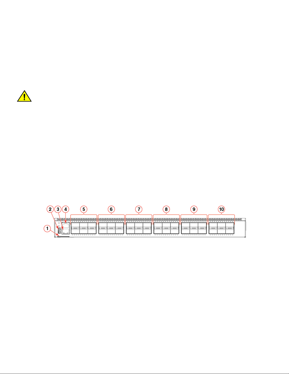
FIGURE 1 Port-side view of the Brocade VDX 6940-36Q
1. Switch ID pull-out tab
2. USB port
3. RJ-45 Ethernet management port
4. RJ-45 serial console port
5. 40 GbE QSFP ports 1-6
6. 40 GbE QSFP ports 7-12
7. 40 GbE QSFP ports 13-18
8. 40 GbE QSFP ports 19-24
9. 40 GbE QSFP ports 25-30
10. 40 GbE QSFP ports 31-36
20 53-1003495-06
Brocade VDX 6940 Hardware Installation Guide
Page 21
Device Overview
Port-side view of VDX 6940-144S
The port side of the Brocade VDX 6940-144S includes the USB port, RJ-45 serial console and Ethernet management port, fixed 10
SFP+ ports, 40 GbE QSFP ports, and system status, power, and port operation LED indicators. Colored labels above and below ports
designate ports that belong to the same trunk group.
The following illustration shows device ports. Refer to LED locations on page 73 for details on port-side LED locations.
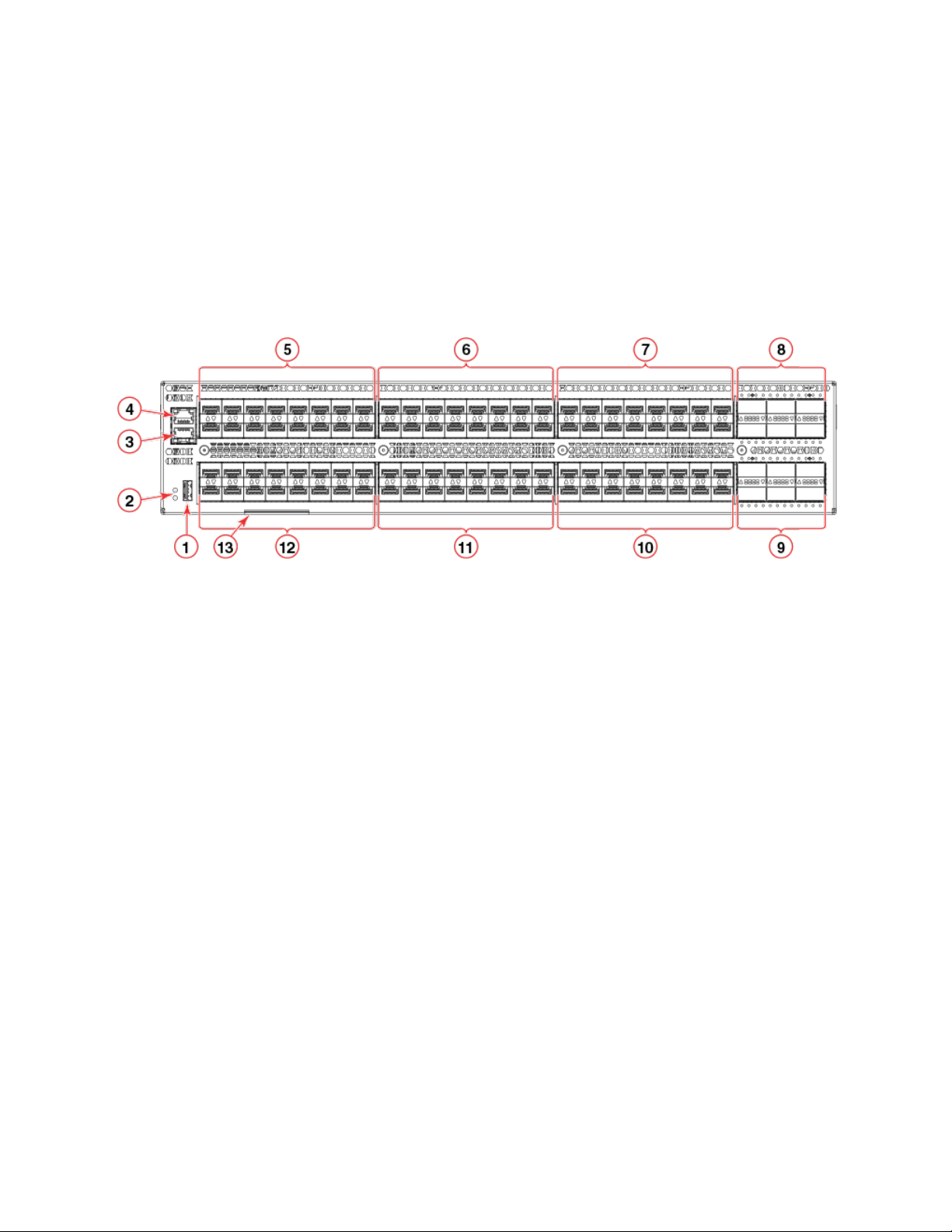
FIGURE 2 Port-side view of Brocade VDX 6940-144S
1. USB port
2. System and power status LEDs
3. RJ-45 serial console port
4. RJ-45 Ethernet management port
5. Fixed 10 GbE SFP+ ports 1-16
6. Fixed 10 GbE SFP+ ports 17-32
7. Fixed 10 GbE SFP+ ports 33-48
8. 40 GbE QSFP ports 97-102 *
9. 40 GbE QSFP ports 103-108*
10. Fixed 10 GbE SFP+ ports 81-96
11. Fixed 10 GbE SFP+ ports 65-80
12. Fixed 10 GbE SFP+ ports 49-64
13. Switch ID pull-out tab
NOTE
*Port 97, 98, 103, and 104 are dual-personality ports and can be configured for 100 GbE or 40 GbE operation. Refer to Dual
personality ports and port groups on page 27 for a diagram of 40 GbE and 100 GbE capable ports contained in dual-
personality port groups.
Brocade VDX 6940 Hardware Installation Guide
53-1003495-06 21
Page 22
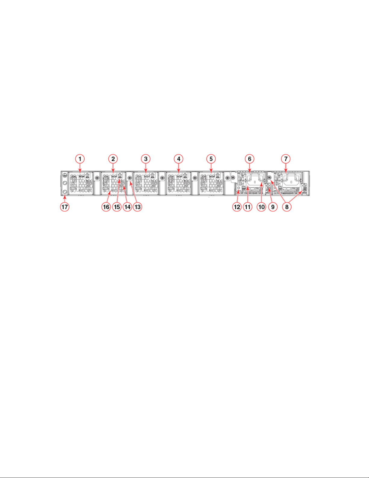
Device Overview
Non-port-side views
Use the following illustrations to locate fan assemblies, AC or DC power supplies, LED status indicators, and other components on
devices.
Non-port-side view of VDX 6940-36Q
The following illustration shows the fan assemblies, AC power supplies, and other components on the non-port side of the Brocade VDX
6940-36Q. Refer to LED locations on page 73 for details on LED locations.
FIGURE 3 Non-port-side view showing AC power supplies
1. Fan #1
2. Fan #2
3. Fan #3
4. Fan #4
5. Fan #5
6. Power supply #1
7. Power supply #2
8. Captive screws
9. Airflow label
10. Plug retainer
11. Plug receptacle
12. Status LED
13. Captive screw
14. Status LED
15. Airflow label
16. Handle
17. Ground lug attachment screws
The following illustration shows the fan assemblies, DC power supplies, and other components on the non-port side of the Brocade
VDX 6940-36Q. Refer to LED locations on page 73 for details on LED locations.
22 53-1003495-06
Brocade VDX 6940 Hardware Installation Guide
Page 23
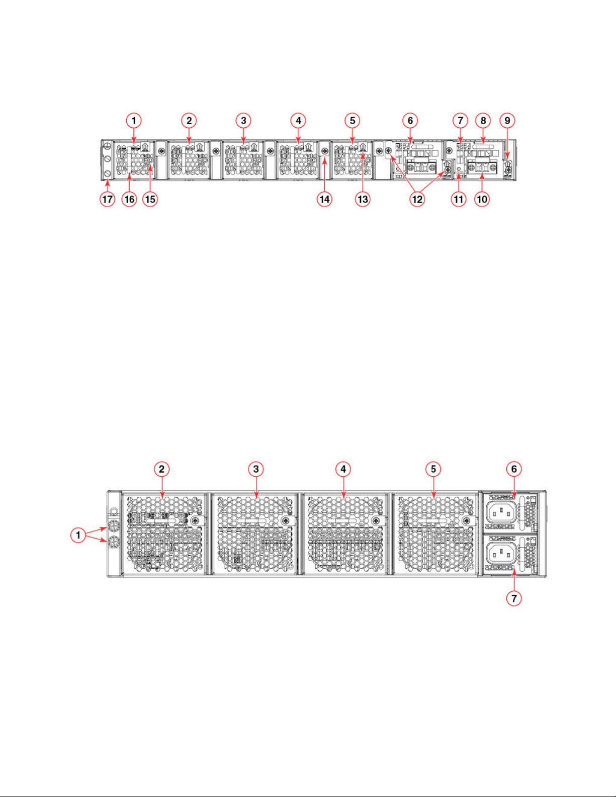
FIGURE 4 Non-port-side view showing DC power supplies
Device Overview
1. Fan #1
2. Fan #2
3. Fan #3
4. Fan #4
5. Fan #5
6. Power supply #1
7. Power supply #2
8. Handle
9. Airflow label
10. DC wire connectors
11. Status LED
12. Captive screws
13. Airflow label
14. Fan captive screw
15. Status LED
16. Handle
17. Ground lug attachment screws
Non-port-side view of VDX 6940-144S
The following illustration shows the fan assemblies, AC power supplies, and other components on the non-port side of the Brocade VDX
6940-144S. Refer to LED locations on page 73 for details on LED locations.
FIGURE 5 Non-port-side view showing AC power supplies
1. Ground lug attachment screws
2. Fan #1
3. Fan #2
4. Fan #3
5. Fan #4
6. AC power supply #1
7. AC power supply #2
Brocade VDX 6940 Hardware Installation Guide
53-1003495-06 23
Page 24

The following illustration shows more detail of the AC power supplies and fans.
FIGURE 6 AC power supply and fan details
Device Overview
1. Fan captive screw
2. AC plug receptacle
3. Power supply handle
4. DC output status LED
5. AC input status LED
6. Power supply airflow label
7. Locking tab
8. Integral fan air inlet
9. Fan status LED
10. Fan handle
11. Fan airflow label
The following illustrations show the fan assemblies, DC power supplies, and other components on the non-port side of the Brocade
VDX 6940-144S. Refer to LED locations on page 73 for details on LED locations.
24 53-1003495-06
Brocade VDX 6940 Hardware Installation Guide
Page 25
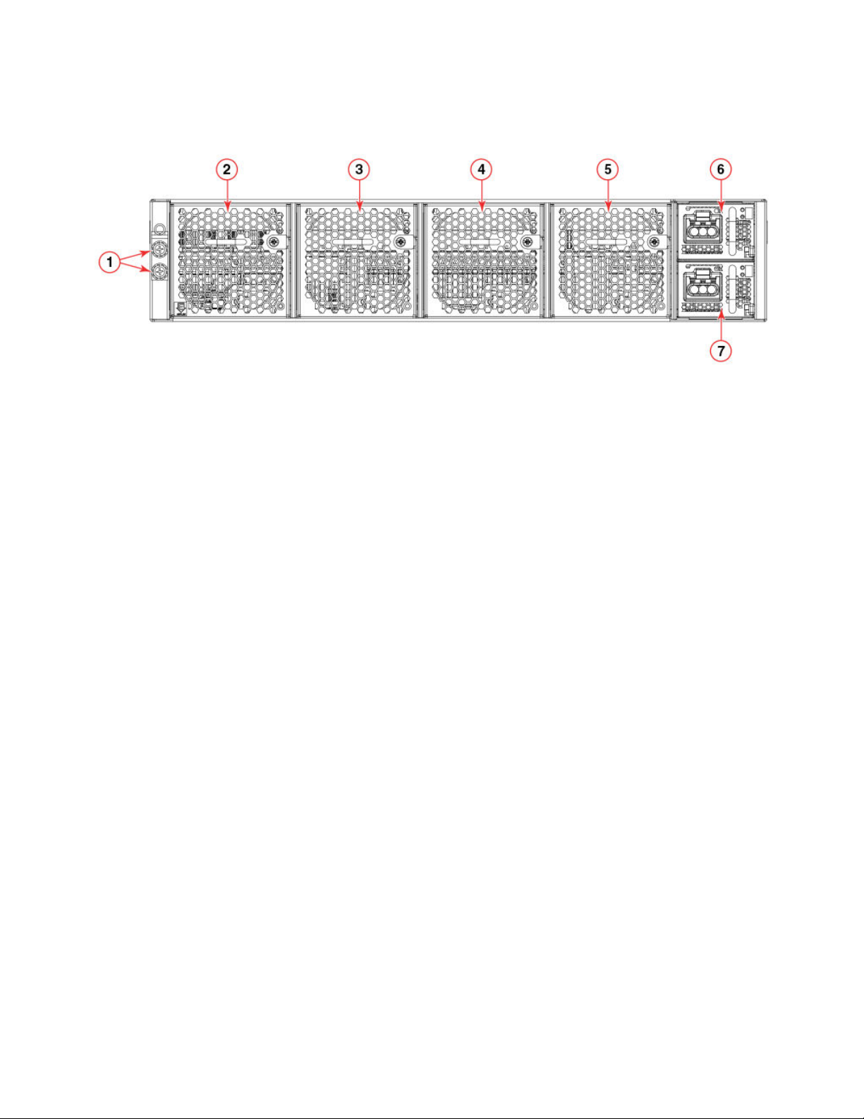
FIGURE 7 Non-port-side view showing DC power supplies
Device Overview
1. Ground lug attachment screws
2. Fan #1
3. Fan #2
4. Fan #3
5. Fan #4
6. DC power supply #1
7. DC power supply #2
The following illustration shows more detail of the fans and DC power supplies.
Brocade VDX 6940 Hardware Installation Guide
53-1003495-06 25
Page 26
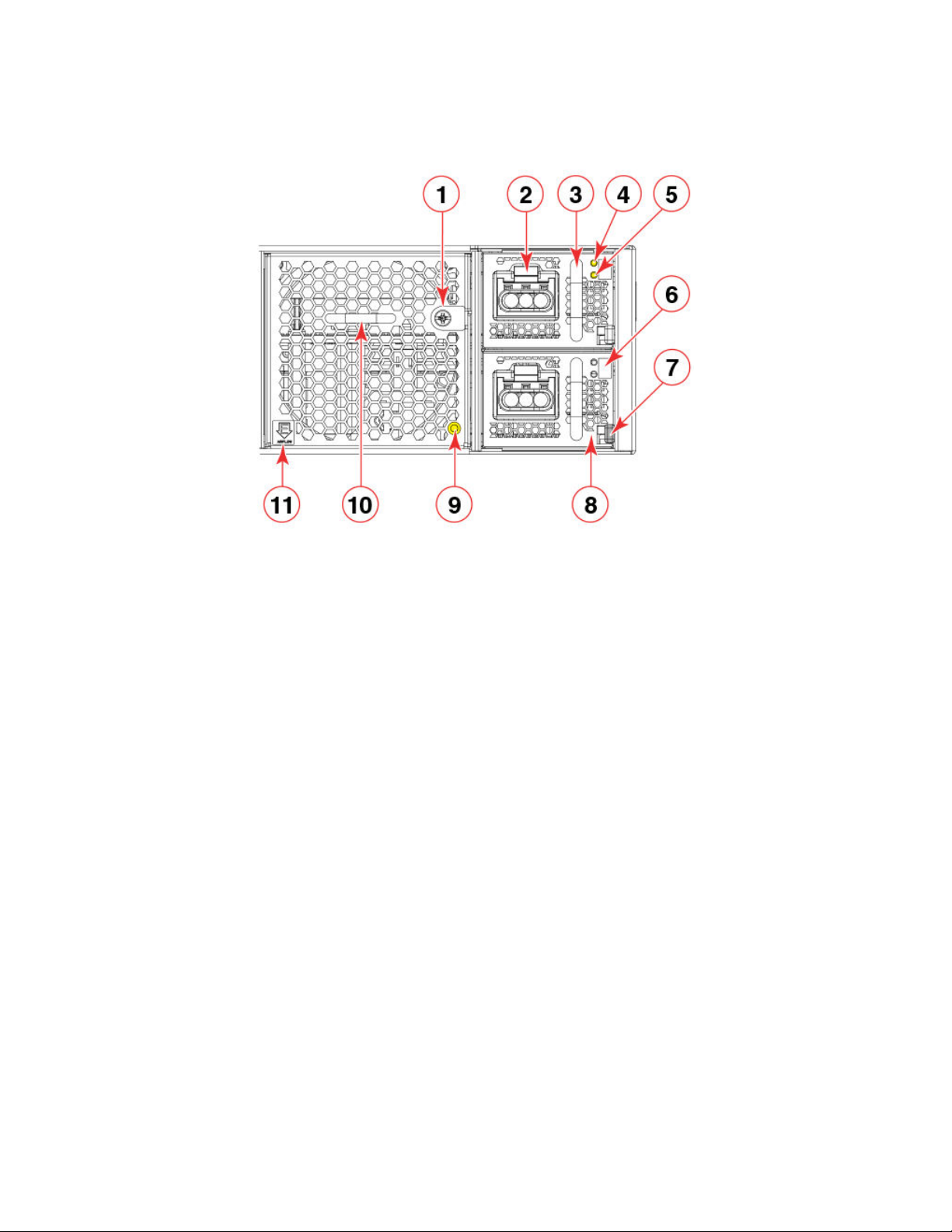
FIGURE 8 DC power supply and fan details
Device Overview
1. Fan captive screw
2. Power cable connector
3. Power supply handle
4. DC input status LED
5. DC output status LED
6. Power supply airflow label
7. Locking tab
8. Integral fan air inlet
9. Fan status LED
10. Fan handle
11. Fan airflow label
Port numbering
Port numbers for GbE ports are required for Network OS commands and management applications to configure connections and
features and determine port operation. Use the following illustrations to determine physical port numbering for Brocade VDX 6940
devices.
VDX 6940-36Q port numbering
For the Brocade VDX 6940-36Q, ports are numbered as follows:
∙ 40 GbE ports are numbered 1 through 36
∙ 10 GbE interfaces for the 40 GbE ports when in 4x10 GbE breakout mode are numbered X:1, X:2, X:3, and X:4, where X is the
40 GbE port number 1 through 36.
As shown in the following illustration, odd-numbered 40 GbE QSFP+ ports are on the top row and even-numbered ports are on the
bottom row.
26 53-1003495-06
Brocade VDX 6940 Hardware Installation Guide
Page 27
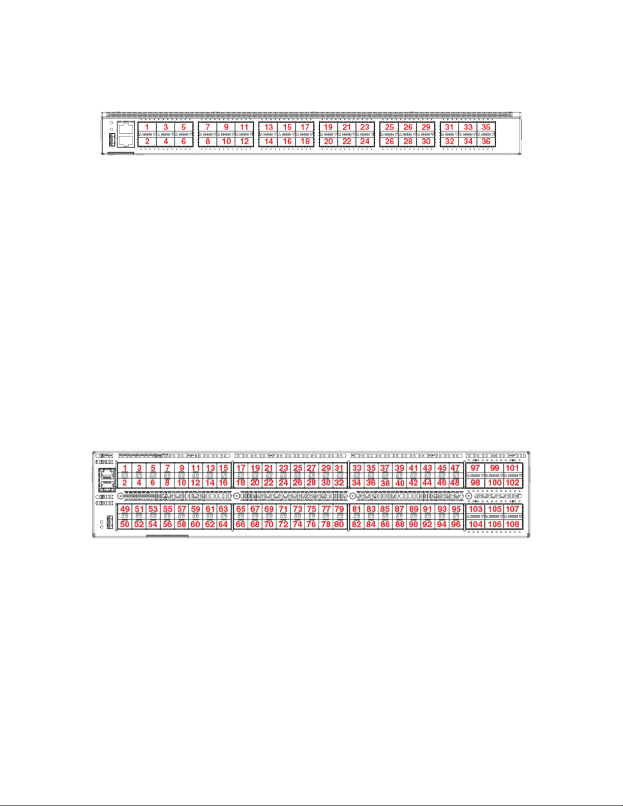
Device Overview
FIGURE 9 Brocade VDX 6940-36Q port numbering
A 40 GbE port configured in 4x10 GbE breakout mode creates four individual 10 GbE interfaces using the 40 GbE port number. For
example, four 10 GbE interfaces for port 36 are numbered as follows:
∙ 36:1
∙ 36:2
∙ 36:3
∙ 36:4
VDX 6940-144S port numbering
For the Brocade VDX 6940-144S, ports are numbered as follows:
∙ Fixed 10 GbE ports are numbered 1 through 96.
∙ 40 GbE ports are numbered 97 through 108.
As shown in the following illustration, the odd-numbered 10 GbE SFP+ and 40 GbE QSFP+ ports are on the top row and evennumbered ports are on the bottom row.
FIGURE 10 Brocade VDX 6940-144S port numbering
Dual personality ports and port groups
The following illustration shows the dual-personality ports and port groups on the Brocade VDX 6940-144S. Dual personality ports can
be configured as 40 GbE QSFP or 100 GbE QSFP28 ports with a qualified 40 GbE or 100 GbE transceiver installed. When a dual
personality port is configured for 100 GbE operation, the remaining 40 GbE ports in the same port group will be disabled. Ports 97, 98,
103, and 104 are dual personality ports.
Brocade VDX 6940 Hardware Installation Guide
53-1003495-06 27
Page 28
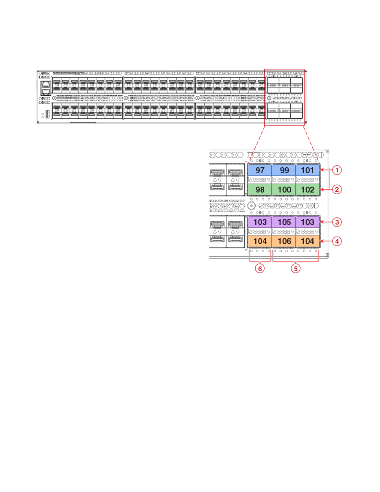
FIGURE 11 Dual -personality ports and port groups
Device Overview
1. Port group 1
2. Port group 2
3. Port group 3
28 53-1003495-06
4. Port group 4
5. 40 GbE ports
6. 100/40 GbE dual personality ports
Brocade VDX 6940 Hardware Installation Guide
Page 29
Preparing for Installation
∙ Installation and safety considerations....................................................................................................................................................................29
∙ Items required for the installation...............................................................................................................................................................................31
∙ Items included with the device...................................................................................................................................................................................32
Installation and safety considerations
You can install this device in the following locations:
∙ In a four-post EIA rack
∙ In a two-post telecommunications (Telco) rack
∙ On a table top as a standalone device
Follow these precautions during installation:
CAUTION
Make sure the airflow around the front, sides, and back of the device is not restricted.
DANGER
The procedures in this manual are for qualified service personnel.
NOTE
It is strongly recommended that you review the Technical Specifications for this device before installation.
Power precautions
To install and operate the device successfully, ensure compliance with the following safety requirements:
∙ The power supply standards provided in the product Technical Specifications are met.
∙ The primary outlets are correctly wired, protected by a circuit breaker, and grounded in accordance with local electrical codes.
DANGER
Connect the power cord only to a grounded outlet.
∙ The supply circuit, line fusing, and wire size are adequate, as specified by the electrical rating on the device nameplate.
∙ This device might have more than one power cord. To reduce the risk of electric shock, disconnect both power cords before
servicing.
DANGER
Disconnect the power cord from all power sources to completely remove power from the device.
DANGER
This product is designed for an IT power system with phase-to-phase voltage of 230V. After operation of the protective device,
the equipment is still under voltage if it is connected to an IT power system.
Brocade VDX 6940 Hardware Installation Guide
53-1003495-06 29
Page 30

Preparing for Installation
CAUTION
All devices with DC power supplies are intended for installation in restricted access areas only. A restricted access area is where
access can be gained only by service personnel through the use of a special tool, lock and key, or other means of security, and
is controlled by the authority responsible for the location.
DANGER
The intra-building port or ports of the equipment or subassembly is suitable for connection to intra-building or unexposed
wiring or cabling only. The intra-building port or ports of the equipment or subassembly MUST NOT be metallically connected
to interfaces that connect to the outside plant (OSP) or its wiring. These interfaces are designed for use as intra-building
interfaces only (Type 2 or Type 4 ports as described in GR-1089-CORE, Issue 5) and require isolation from the exposed OSP
cabling. The addition of Primary Protectors is not sufficient protection in order to connect these interfaces metallically to OSP
wiring.
CAUTION
The Brocade device must be connected to external Special Protection Devices (SPD) when installed and connected to
commercial AC power.
NOTE
The unit is suitable for installation as part of the Common Bonding Network (CBN).
For the 500W DC power supply used on the Brocade VDX 6940-36Q, use the following caution.
CAUTION
For the DC input circuit to the system, make sure there is a 20 Amp circuit breaker, minimum -48 VDC, double pole, on the
input terminal block to the power supply. The input wiring for connection to the product should be copper wire, 12 AWG,
marked VW-1, and rated minimum 90°C.
For the 1100W DC power supply used on the Brocade VDX 6940-144S, use the following caution.
CAUTION
For the DC input circuit to the system, make sure there is a 40-amp circuit breaker, minimum 60 VDC, double pole, on the
input to the terminal block. The input wiring for connection to the product should be copper wire, 8 AWG, marked VW-1, and
rated a minimum of 90 degrees celsius.
Environmental precautions
For successful installation and operation of the device, ensure that the following environmental requirements are met:
∙ Fans supplied with the device move air either front to back (exhaust) or back to front (intake). Be sure to align the device with the
airflow pattern of any other devices in the rack. All equipment in the rack should force air in the same direction to avoid intake of
exhaust air.
CAUTION
Ensure that the airflow direction of the power supply unit matches that of the installed fan tray. The power supplies and
fan trays are clearly labeled with either a green arrow with an "E", or an orange arrow with an "I."
∙ Ensure that the airflow available at intake vents allows the maximum airflow as specified in the product Technical Specifications.
∙ Ensure that the ambient air temperature does not exceed that specified for maximum operational temperate in the product
Technical Specifications.
30 53-1003495-06
Brocade VDX 6940 Hardware Installation Guide
Page 31

Preparing for Installation
EIA rack considerations
For successful installation and operation of the device in a rack, ensure the following rack requirements are met:
∙ The rack must be a standard EIA rack.
∙ For 1U devices, the rack space required is one rack unit (1U) 44.45 mm (1.75 in.) high and 440 mm (17.5 in.) wide.
∙ The equipment in the rack is grounded through a reliable branch circuit connection and maintains ground at all times. Do not
rely on a secondary connection to a branch circuit, such as a power strip.
∙ Ensure that the rack mounting does not impede airflow or negatively affect temperature requirements, particularly if the device
is installed in a closed or multirack assembly. Ensure that airflow openings on the port and nonport side of the device are not
obstructed.
CAUTION
Make sure the airflow around the front, sides, and back of the device is not restricted.
∙ The additional weight of the device does not exceed the rack’s weight limits or unbalance the rack in any way.
∙ The rack is secured to ensure stability in case of unexpected movement, such as an earthquake.
DANGER
Make sure the rack housing the device is adequately secured to prevent it from becoming unstable or falling over.
Recommendations for cable management
The minimum radius to which a 50-micron cable can be bent under full tensile load is 5.1 cm (2 in.). For a cable under no tensile load,
that minimum is 3.0 cm (1.2 in.).
Cables can be organized and managed in a variety of ways; for example, use cable channels on the sides of the EIA rack or patch panels
to reduce the potential for tangling the cables. The following list provides some recommendations for cable management:
NOTE
You should not use tie wraps with optical cables because they are easily overtightened and can damage the optic fibers. Velcrolike wraps are recommended.
∙ Plan for the rack space required for cable management before installing the device.
∙ Leave at least 1 m (3.28 ft) of slack for each port cable. This provides room to remove and replace the device, allows for
inadvertent movement of the rack, and helps prevent the cables from being bent to less than the minimum bend radius.
∙ For easier maintenance, label the cables and record the devices to which they are connected.
∙ Keep LEDs visible by routing port cables and other cables away from the LEDs.
Items required for the installation
The following items are required for installing, configuring, and connecting the device for use in a network and fabric:
∙ A workstation with an installed terminal emulator, such as HyperTerminal.
∙ An unused IP address and corresponding subnet mask and gateway address.
∙ A serial cable (provided).
∙ An Ethernet cable.
∙ Power cord (provided).
Brocade VDX 6940 Hardware Installation Guide
53-1003495-06 31
Page 32

Preparing for Installation
∙ (Optional) Access to an FTP server or Brocade-branded USB device for backing up the device configuration.
∙ (Optional) If mounting in the iDataplex IBM 15.5-inch depth rack, the Brocade iDataplex rack mount kit.
Items included with the device
The following items are included with the standard shipment of a fully-configured Brocade VDX 6940. When you open the packaging,
verify that the items are included in the package and that no damage has occurred during shipping.
∙ The Brocade VDX 6940 chassis.
∙ Transceivers and cables as ordered
∙ One accessory kit, containing the following items:
– Serial cable with an RJ-45 connector
– 6 ft. AC power cords (2)
– 8 ft. DC harness assembly (2) forBrocade VDX 6940-144S with DC power supplies.
– Ground lug kit
– Rubber feet, required for setting up the device as a standalone unit
– China RoHS hazardous/toxic substance content chart
– EULA/Read-Me document
– USB drive, 4G
– Web pointer card for documentation
32 53-1003495-06
Brocade VDX 6940 Hardware Installation Guide
Page 33

Mounting the device
∙ Mounting options.............................................................................................................................................................................................................. 33
∙ Mounting precautions.....................................................................................................................................................................................................33
∙ Standalone installation .................................................................................................................................................................................................. 34
∙ Installing the Universal Four-Post Rack Kit (XBR-R000296)...............................................................................................................34
∙ Installing the Universal Two-Post Rack kit (XBR-R000294).................................................................................................................48
Mounting options
You can install the device in several ways:
∙ As a standalone unit on a flat surface, for example a desk top. Use the rubber feet included with the shipment to secure the
device on the surface. No other equipment is required for desktop installation.
∙ In a four-post EIA rack: You will need a Universal Four-Post Rack Kit (XBR-R000296) to install devices in EIA racks that are
between L-13.7 to 81.28 cm deep (L-5.0 to 32.0 in.), where L is the chassis depth.
∙ In a two-post Telco rack: You will need a Universal Two-Post Rack Kit (XBR-R000294) to install 1U and 2U devices in a two-
post telecommunications (Telco) rack.
NOTE
These rack mount kits are supported for this device at the date of this publication. For the latest support information, contact
your Brocade representative.
Mounting precautions
The following precautions specifically apply to mounting the device.
CAUTION
Make sure the airflow around the front, sides, and back of the device is not restricted.
CAUTION
Never leave tools inside the chassis.
DANGER
Use safe lifting practices when moving the product.
DANGER
Mount the devices you install in a rack as low as possible. Place the heaviest device at the bottom and progressively place
lighter devices above.
CAUTION
Do not use the port cover tabs to lift the module. They are not designed to support the weight of the module, which can fall and
be damaged.
CAUTION
To prevent damage to the chassis and components, never attempt to lift the chassis using the fan or power supply handles.
These handles were not designed to support the weight of the chassis.
Brocade VDX 6940 Hardware Installation Guide
53-1003495-06 33
Page 34

Mounting the device
Standalone installation
Complete the following steps to install the device as a standalone unit on a table top.
1. Unpack the device and verify the items listed under "Items included with this device" are present and undamaged.
2. Apply the adhesive rubber feet to the device. The rubber feet help prevent the device from sliding off the supporting surface.
a) Clean the indentations at each corner of the bottom of the device to ensure that they are free of dust or other debris that
might lessen the adhesion of the feet.
b) With the adhesive side against the chassis, place one rubber foot in each indentation and press into place.
3. Place the device on a flat, sturdy surface.
4. Provide power to the device as described under "Providing power to the device."
NOTE
Do not connect the device to the network until the IP address is correctly set. For instructions on how to set the IP
address, refer to "Configuring the device IP address."
Installing the Universal Four-Post Rack Kit (XBR-R000296)
Use the following instructions to install a device in EIA racks that are between L-12.7 to 81.28 cm deep (L-5.0 to 32.0 in.), where L is the
chassis depth, using the
Universal Four-Post Rack Kit (XBR-R000296)
.
There are two ways you can mount the device in a four-post rack:
∙ With the port side flush with the front posts
∙ With the nonport side flush with the rear posts in a recessed position
A recessed position allows a more gradual bend in the fiber-optic cables connected to the switch and less interference in the aisle at the
front of the rack.
NOTE
Although this document describes how to install both single height (1U) and double height (2U) switches, the illustrations show a
1U switch as a typical installation.
NOTE
Hardware devices illustrated in these procedures are only for reference and may not depict the device you are installing into the
rack.
Installation requirements
Provide space in an EIA rack with the following minimum and maximum distances between the front and back posts.
NOTE
For 1U and 2U devices, two people are required to install the device in a rack. One person holds the device, while the other
screws in the front and rear "L" brackets.
TABLE 7 Space requirements
Chassis with port-side
side vents
No Applicable to port-side and nonport-side flush
Yes Applicable to port-side flush mounts. L L-12.7 cm (L-5 in.) 81.28 cm (32 in.)
Notes Chassis depth Minimum rack depth Maximum rack depth
L L-12.7 cm (L-5 in.) 81.28 cm (32 in.)
mounts.
34 53-1003495-06
Brocade VDX 6940 Hardware Installation Guide
Page 35

Mounting the device
TABLE 7 Space requirements (continued)
Chassis with port-side
side vents
Yes Applicable to nonport-side flush mounts. L L 81.28 cm (32 in.)
Notes Chassis depth Minimum rack depth Maximum rack depth
Note that if chassis depth (L) is less than 40.64 cm (16 in.), the chassis will not fit into a rack with a maximum depth of 81.28 cm (32 in.)
using the universal four-post rack kit. The maximum rack depth for a chassis less than 40.64 cm (16 in.) is 81.28 cm (32 in.) minus the
difference between the chassis depth and 40.64 cm (16 in.). For example, a chassis with a depth (L) of 35.56 cm (14 in.) is 5.08 cm (2 in.)
smaller than 40.64 cm (16 in.), so it will install into a rack with a maximum depth of 81.28 cm (32 in.) - 5.08 cm (2 in.) = 76.2 cm (30 in.).
Review the installation and facility requirements for your product before mounting the device . Refer to the
for your product for more information.
Time and items required
Allow 15 to 30 minutes to complete the installation.
The following items are required to install the device using the Universal Four-Post Rack Kit:
∙ #2 Phillips torque screwdriver
∙ 1/4-inch slotted-blade torque screwdriver
Hardware Installation Guide
Brocade VDX 6940 Hardware Installation Guide
53-1003495-06 35
Page 36

FIGURE 12 Items in the Universal Four-Post Rack Kit
Mounting the device
1. Front brackets (2)
2. Extension brackets, medium (2)
3. Rear brackets, short (2)
4. Rear brackets, long (2)
5. Extension brackets, long (2)
6. Screw, 8-32 x 5/16-in., panhead Phillips (8)
7. Screw, 8-32 x 5/16-in., flathead Phillips (16)
8. Screw, 6-32 x 1/4-in., panhead Phillips (8)
9. Screw, 10-32 x 5/8-in., panhead Phillips (8)
10. Retainer nut, 10-32 (8)
Ensure that the items listed and illustrated in Figure 12 are included in the kit. Note that not all parts may be used with certain installations
depending on the device type.
CAUTION
Use the screws specified in the procedure. Using longer screws can damage the device.
36 53-1003495-06
Brocade VDX 6940 Hardware Installation Guide
Page 37

Flush-front mounting
CAUTION
The device must be turned off and disconnected from the fabric during this procedure.
NOTE
The illustrations in the rack installation procedures show a 1U device, but the instructions are the same for a 2U device. The
illustrations in the rack installation procedures are for reference only and may not show the actual device.
Complete the following tasks to install the device in a four-post rack:
1. Attaching the front brackets on page 37
2. Attaching the extension brackets to the device on page 38
3. Installing the device in the rack on page 39
4. Attaching the rear brackets to the extensions on page 40
5. Attaching the rear brackets to the rack posts on page 41
Attaching the front brackets
Complete the following steps to attach the front brackets to the device.
Mounting the device
1. Position the right front bracket with the flat side against the right side of the device at the front of the device, as shown in Figure
13.
2. Insert four 8-32 x 5/16-in. flathead screws through the vertically aligned holes in the bracket and then into the holes on the side
of the device. Use the upper and lower screw holes, leaving the center holes empty.
3. Repeat step 1 and step 2 to attach the left front bracket to the left side of the device.
4. Tighten all the 8-32 x 5/16-in. screws to a torque of 15 in-lb (17 cm-kg).
Brocade VDX 6940 Hardware Installation Guide
53-1003495-06 37
Page 38

FIGURE 13 Attaching the front brackets
Mounting the device
1. The Brocade device
2. Front brackets
3. Screws, 8-32 x 5/16-in., flathead Phillips
Attaching the extension brackets to the device
Complete the following steps to attach the extension brackets to the device. There are medium and long extension brackets that you can
use for this step. Choose the correct extension bracket for the depth of your rack.
1. Select the proper length extension bracket for your rack depth.
2. Position the right extension bracket along the side of the device as shown in Figure 14.
3. Insert four 8-32 x 5/16-in. flathead screws through the vertically aligned holes in the extension bracket and then into the holes
on the side of the device. Use the upper and lower screw holes, leaving the center holes empty.
4. Repeat step 1 and step 2 to attach the left extension bracket to the left side of the device.
5. Tighten all the 8-32 x 5/16-in. screws to a torque of 15 in-lb (17 cm-kg).
38 53-1003495-06
Brocade VDX 6940 Hardware Installation Guide
Page 39

FIGURE 14 Attaching the extension brackets to the device
Mounting the device
1. Extension brackets 2. Screws, 8-32 x 5/16-in., flathead Phillips
Installing the device in the rack
Complete the following steps to install the device in the rack.
1. Position the device in the rack, as shown in Figure 15, providing temporary support under the device until the rail kit is secured
to the rack.
2. Attach the right front bracket to the right front rack post using two 10-32 x 5/8-in. panhead screws and two retainer nuts. Use
the upper and lower holes in the bracket.
3. Attach the left front bracket to the left front rack post using two 10-32 x 5/8-in. panhead screws and two retainer nuts. Use the
upper and lower holes in the bracket.
4. Tighten all the 10-32 x 5/8-in. screws to a torque of 25 in-lb (29 cm-kg).
Brocade VDX 6940 Hardware Installation Guide
53-1003495-06 39
Page 40

FIGURE 15 Positioning the device in the rack
Mounting the device
1. Screws, 10-32 x 5/8-in., panhead Phillips 2. Retainer nuts, 10-32
Attaching the rear brackets to the extensions
Complete the following steps to attach the rear brackets to the extensions. There are short and long rear brackets that you can use for
this step. Choose the correct bracket for the depth of your rack.
1. Select the proper length rear bracket for your rack depth.
2. Slide the right rear bracket onto the right extension and attach to the extension by inserting four 6-32 x 1/4-in. panhead screws
through the bracket holes. If possible, leave at least one empty vertical pair of holes between the screws for better support.
3. Repeat step 2 to attach the left rear bracket to the left extension.
4. Adjust the brackets to the rack depth and tighten all the 6-32 x 1/4-in. screws to a torque of 9 in-lb (10 cm-kg).
40 53-1003495-06
Brocade VDX 6940 Hardware Installation Guide
Page 41

FIGURE 16 Attaching the rear brackets to the extensions
Mounting the device
1. Rear brackets 2. Screws, 6-32 x 1/4-in., panhead Phillips
Attaching the rear brackets to the rack posts
Complete the following steps to attach the rear brackets to the rack posts.
1. Attach the right rear bracket to the right rear rack post using two 10-32 x 5/8-in. panhead screws and two retainer nuts, as
shown in Figure 17. Use the upper and lower holes in the bracket.
2. Attach the left rear bracket to the left rear rack post using two 10-32 x 5/8-in. panhead screws and two retainer nuts. Use the
upper and lower holes in the bracket.
3. Tighten all the 10-32 x 5/8-in. screws to a torque of 25 in-lb (29 cm-kg).
Brocade VDX 6940 Hardware Installation Guide
53-1003495-06 41
Page 42

FIGURE 17 Attaching the rear brackets to the rack posts
Mounting the device
1. Screws, 10-32 x 5/8-in., panhead Phillips 2. Retainer nuts, 10-32
Flush-rear (recessed) mounting
The flush-rear (recessed) mounting is similar to the flush-front mounting except that the brackets are reversed on the device.
CAUTION
The device must be turned off and disconnected from the fabric during this procedure.
NOTE
The illustrations in the rack installation procedures show a 1U device, but the instructions are the same for a 2U device. The
illustrations in the rack installation procedures are for reference only and may not show the actual device.
Complete the following tasks to install the device in a four-post rack:
1. Attaching the front brackets to the rear of the device on page 42
2. Attaching the extensions to the front of the device on page 43
3. Installing the device in the rack on page 44
4. Attaching the rear brackets to the extensions at the front of the device on page 45
5. Attaching the rear brackets to the front rack posts on page 47
Attaching the front brackets to the rear of the device
NOTE
In this installation, the brackets are named as listed in the parts list even though the installation of the brackets is reversed from
the flush-front installation.
42 53-1003495-06
Brocade VDX 6940 Hardware Installation Guide
Page 43

Mounting the device
Complete the following steps to attach the front brackets to the rear of the device.
1. Position the right front bracket with the flat side against the right rear side of the device, as shown in Figure 18.
2. Insert four 8-32 x 5/16-in. flathead screws through the vertically aligned holes in the bracket and then into the holes on the side
of the device. Use the upper and lower screw holes, leaving the center holes empty.
3. Repeat step 1 and step 2 to attach the left rear bracket to the left side of the device.
4. Tighten all the 8-32 x 5/16-in. screws to a torque of 15 in-lb (17 cm-kg).
FIGURE 18 Attaching the front brackets to the rear of the device
1. The Brocade device
2. Screws, 8-32 x 5/16-in., flathead Phillips
3. Front brackets
Attaching the extensions to the front of the device
Complete the following steps to attach the extension brackets to the front of the device. There are medium and long extension brackets
that you can use for this step. Choose the correct extension for the depth of your rack.
1. Select the proper length extension bracket for your rack depth.
2. Position the right extension along the side of the device as shown in Figure 19.
3. Attach the bracket using four 8-32 x 5/16-in. flathead screws.
4. Repeat step 1 and step 2 to attach the left front extension to the left side of the device.
5. Tighten all the 8-32 x 5/16-in. screws to a torque of 15 in-lb (17 cm-kg).
Brocade VDX 6940 Hardware Installation Guide
53-1003495-06 43
Page 44

FIGURE 19 Attaching the bracket extensions to the device
Mounting the device
1. Extension brackets 2. Screws, 8-32 x 5/16-in., flathead Phillips
Installing the device in the rack
Complete the following steps to install the device in the rack.
1. Position the device in the rack, as shown in Figure 20, providing temporary support under the device until the rail kit is secured
to the rack.
2. Attach the right front bracket to the right rear rack post using two 10-32 x 5/8-in. panhead screws and two retainer nuts. Use
the upper and lower holes in the bracket.
3. Attach the left front bracket to the left rear rack post using two 10-32 x 5/8-in. panhead screws and two retainer nuts. Use the
upper and lower holes in the bracket.
4. Tighten all the 10-32 x 5/8-in. screws to a torque of 25 in-lb (29 cm-kg).
44 53-1003495-06
Brocade VDX 6940 Hardware Installation Guide
Page 45

FIGURE 20 Positioning the device in the rack
Mounting the device
1. Screws, 10-32 x 5/8-in., panhead Phillips 2. Retainer nuts, 10-32
Attaching the rear brackets to the extensions at the front of the device
Complete the following steps to attach the rear brackets to the extensions. There are short and long front brackets that you can use for
this step. Choose the correct bracket for the depth of your rack.
1. Select the proper length rear bracket for your rack depth.
2. Slide the right rear bracket onto the right extension, as shown in Figure 21.
The short rear brackets are shown. Use the first and third vertical pairs of holes for the screws.
Refer to Figure 22 for the positioning of the short or long brackets and screws.
3. Attach the brackets using four 6-32 x 1/4-in. screws.
4. Repeat step 2 and step 3 to attach the left rear bracket to the left extension.
5. Adjust the brackets to the rack depth and tighten all the 6-32 x 1/4-in. screws to a torque of 9 in-lb (10 cm-kg).
Brocade VDX 6940 Hardware Installation Guide
53-1003495-06 45
Page 46

FIGURE 21 Attaching the rear brackets to the extensions at the front of the device
Mounting the device
1. Rear brackets, short 2. Screws, 6-32 x 1/4-in., panhead Phillips
46 53-1003495-06
Brocade VDX 6940 Hardware Installation Guide
Page 47

FIGURE 22 Attaching the short or long rear brackets to the extensions
Mounting the device
1. Rear bracket, short or long 2. Screws, 6-32 x 1/4-in., panhead Phillips
Attaching the rear brackets to the front rack posts
Complete the following steps to attach the rear brackets to the front rack posts.
1. Attach the right rear bracket to the right front rack post using two 10-32 x 5/8-in. screws and two retainer nuts, as shown in
Figure 23. Use the upper and lower holes in the bracket.
2. Attach the left rear bracket to the left front rack post using two 10-32 x 5/8-in. screws and two retainer nuts. Use the upper and
lower holes in the bracket.
3. Tighten all the 10-32 x 5/8-in. screws to a torque of 25 in-lb (29 cm-kg).
Brocade VDX 6940 Hardware Installation Guide
53-1003495-06 47
Page 48

FIGURE 23 Attaching the rear brackets to the front rack posts
Mounting the device
1. Screws, 10-32 x 5/8-in., panhead Phillips 2. Retainer nuts, 10-32
Installing the Universal Two-Post Rack kit (XBR-R000294)
Use the following instructions to install a Brocade 1U or 2U device in a two-post telecommunications (Telco) rack using the Universal
Two-Post Rack Kit (XBR-R000294). Any updates to these instructions will be added to the hardware installation guide for your product.
There are two ways you can mount the device in a two-post rack:
∙ With the port side flush with the front posts
∙ With the posts mounted to the mid-section of the device
NOTE
Hardware devices illustrated in these procedures are only for reference and may not depict the device you are installing into the
rack.
Installation requirements
Review the installation and facility requirements for your product before mounting the device . Refer to the hardware installation guide for
your product for more information.
Lifting requirements
For 1U and 2U devices, two people are required to install the device in a rack. One person holds the device, while the other screws in the
front and rear "L" brackets.
48 53-1003495-06
Brocade VDX 6940 Hardware Installation Guide
Page 49

Time and items required
Allow 15 to 30 minutes to complete the installation.
The following items are required to install the device using the Universal Two-Post Rack Kit:
∙ #2 Phillips torque screwdriver
∙ 1/4-inch slotted-blade torque screwdriver
CAUTION
Use the screws specified in the procedure. Using longer screws can damage the device.
Flush-front mounting
Observe the following notes when using this procedure:
∙ The device must be turned off and disconnected from the fabric during this procedure.
∙ The illustrations in this document show a 1U device, but the instructions are the same for a 2U device.
∙ The illustrations for this procedure show a two-post rack with narrow posts (3- to 5-inch) as an example.
∙ The illustrations in the rack installation procedures are for reference only and may not show the actual device.
Mounting the device
Complete the following tasks to install the device in a rack:
1. Attaching the front brackets to the device on page 49
2. Attaching the front brackets to the rack on page 50
3. Attaching the rear brackets to the rack on page 51
4. Attaching the rear brackets to the device on page 52
Attaching the front brackets to the device
Complete the following steps to attach the front brackets to the device.
1. Position the right front bracket with the flat side against the right side of the device, as shown in Figure 24.
2. Insert four 8-32 x 5/16-in. flathead screws through the vertically aligned holes in the bracket and then into the holes on the side
of the device. Use the upper and lower screw holes, leaving the center holes empty.
3. Repeat step 1 and step 2 to attach the left front bracket to the left side of the device.
4. Tighten all the 8-32 x 5/16-in. screws to a torque of 15 in-lb (17 cm-kg).
Brocade VDX 6940 Hardware Installation Guide
53-1003495-06 49
Page 50

FIGURE 24 Attaching the front brackets
Mounting the device
1. The Brocade device
2. Front brackets, right and left
3. Screws, 8-32 x 5/16-in., flathead Phillips
Attaching the front brackets to the rack
Complete the following steps to install the device in the rack.
1. Position the device in the rack, as shown in (Figure 25), providing temporary support under the device until the rack kit is fully
secured to the rack.
2. Attach the right front bracket to the right rack upright using two 10-32 x 5/8-in. panhead screws and two retainer nuts. Use the
upper and lower holes in the bracket.
3. Attach the left front bracket to the left rack upright using two 10-32 x 5/8-in. panhead screws and two retainer nuts.
4. Use the upper and lower holes in the bracket. Tighten all the 10-32 x 5/8-in. screws to a torque of 25 in-lb. (29 cm-kg).
50 53-1003495-06
Brocade VDX 6940 Hardware Installation Guide
Page 51

FIGURE 25 Attaching front brackets to a rack
Mounting the device
1. Screws, 10-32 x 5/8-in., panhead Phillips 2. Retainer nuts, 10-32
Attaching the rear brackets to the rack
Complete the following steps to attach the rear brackets to the rack.
1. Select the proper length bracket for your post width. If your posts are three to five inches wide, use the brackets marked 3-5
INCH. If your posts are five to six inches wide, use the brackets marked 5-6 INCH.
2. Position the right rear bracket in the right rear of the device, as shown in Figure 26.
3. Attach the bracket to the right rack upright using two 10-32 x 5/8-in. panhead screws and two retainer nuts. Use the upper and
lower holes in the bracket.
4. Repeat step 2 and step 3 to attach the left rear bracket to the left rack upright.
5. Tighten all the 10-32 x 5/8-in. screws to a torque of 25 in-lb. (29 cm-kg).
Brocade VDX 6940 Hardware Installation Guide
53-1003495-06 51
Page 52

FIGURE 26 Attaching the rear brackets to a rack
Mounting the device
1. Retainer nuts, 10-32
2. Rear brackets
3. Screws, 10-32 x 5/8-in., panhead Phillips
Attaching the rear brackets to the device
Complete the following steps to attach the rear brackets to the device.
1. Align the right rear bracket to the right rear of the device and use four 8-32 x 5/16-in. panhead screws to attach the bracket to
the device, as shown in Figure 27. Be sure to insert the screws through the upper and lower slots in the bracket.
2. Align the left rear bracket to the left rear of the device and use four 8-32 x 5/16-in. panhead screws to attach the bracket to the
device. Again, use the upper and lower slots in the bracket.
3. Tighten all the 8-32 x 5/16-in. screws to a torque of 15 in-lb (17 cm-kg).
52 53-1003495-06
Brocade VDX 6940 Hardware Installation Guide
Page 53

FIGURE 27 Attaching the rear brackets to the device
Mounting the device
1. Screws, 8-32 x 5/16-in., panhead Phillips
Mid-mounting
Observe the following notes when using this procedure:
∙ The device must be turned off and disconnected from the fabric during this procedure.
∙ The illustrations in this document show a 1U device, but the instructions are the same for a 2U device.
∙ The illustrations in the rack installation procedures are for reference only and may not show the actual device.
Complete the following tasks to install the device in a rack:
1. Attaching the front brackets to the device on page 53
2. Attaching the front brackets to the rack on page 54
3. Attaching the rear brackets to the rack on page 55
4. Attaching the rear brackets to the device on page 56
Attaching the front brackets to the device
Complete the following steps to attach the front brackets to the device.
1. Position the right front bracket with the flat side against the right side of the device, as shown in Figure 28.
2. Insert four 8-32 x 5/16-in. flathead screws through the vertically aligned holes in the bracket and then into the holes on the side
of the device. Use the upper and lower screw holes, leaving the center holes empty.
3. Repeat step 1 and step 2 to attach the left front bracket to the left side of the device.
4. Tighten all the 8-32 x 5/16-in. screws to a torque of 15 in-lb (17 cm-kg).
Brocade VDX 6940 Hardware Installation Guide
53-1003495-06 53
Page 54

FIGURE 28 Attaching the front brackets
Mounting the device
1. The Brocade device
2. Front brackets, right and left
3. Screws, 8-32 x 5/16-in., flathead Phillips
Attaching the front brackets to the rack
Complete the following steps to install the device in the rack.
1. Position the device in the rack, as shown in Figure 29, providing temporary support under the device until the rack kit is fully
secured to the rack.
2. Attach the right front bracket to the right rack upright using two 10-32 x 5/8-in. screws and two retainer nuts. Use the upper
and lower holes in the bracket.
3. Attach the left front bracket to the left rack upright using two 10-32 x 5/8-in. screws and two retainer nuts. Use the upper and
lower holes in the bracket.
4. Tighten all the 10-32 x 5/8-in. screws to a torque of 25 in-lb (29 cm-kg).
54 53-1003495-06
Brocade VDX 6940 Hardware Installation Guide
Page 55

FIGURE 29 Attaching front brackets to a rack
Mounting the device
1. Screws, 10-32 x 5/8-in., panhead Phillips 2. Retainer nuts, 10-32
Attaching the rear brackets to the rack
Complete the following steps to attach the rear brackets to the rack.
1. Select the proper length bracket for your post width. If your posts are three to five inches wide, use the brackets marked 3-5
INCH. If your posts are five to six inches wide, use the brackets marked 5-6 INCH.
2. Position the right rear bracket in the right rear of the device, as shown in the following figure. Whether you are using the 3-5
inch or the 5-6 inch bracket, the rear end of the bracket will be flush with the back of the device.
3. Attach the brackets to the right rack upright using two 10-32 x 5/8-in. panhead screws and two retainer nuts.
4. Repeat step 2 and step 3 to attach the left rear bracket to the left rack upright.
5. Tighten all the 10-32 x 5/8-in. screws to a torque of 25 in-lb (29 cm-kg).
Brocade VDX 6940 Hardware Installation Guide
53-1003495-06 55
Page 56

FIGURE 30 Attaching the rear brackets to a rack
Mounting the device
1. Retainer nuts, 10-32
2. Retainer nuts, 10-32
3. Rear brackets (right and left)
4. Screws, 10-32 x 5/8-in., panhead Phillips
Attaching the rear brackets to the device
Complete the following steps to attach the rear brackets to the device.
1. Align the right rear bracket to the right rear of the device and use four 8-32 x 5/16-in. panhead screws to attach the bracket to
the device, as shown in Figure 31. Be sure to insert the screws through the upper and lower slots in the bracket.
2. Align the left rear bracket to the left rear of the device and use four 8-32 x 5/16-in. panhead screws to attach the bracket to the
device. Again, use the upper and lower slots in the bracket.
3. Tighten all the 8-32 x 5/16-in. screws to a torque of 15 in-lb (17 cm-kg).
56 53-1003495-06
Brocade VDX 6940 Hardware Installation Guide
Page 57

FIGURE 31 Attaching the rear brackets to the device
Mounting the device
1. Screws, 8-32 x 5/16-in., panhead Phillips
Brocade VDX 6940 Hardware Installation Guide
53-1003495-06 57
Page 58

Mounting the device
58 53-1003495-06
Brocade VDX 6940 Hardware Installation Guide
Page 59

Initial Configuration
∙ Configuration overview.................................................................................................................................................................................................. 59
∙ Items required.....................................................................................................................................................................................................................60
∙ Providing power to the device...................................................................................................................................................................................60
∙ Verifying operation............................................................................................................................................................................................................65
∙ Establishing a serial connection................................................................................................................................................................................66
∙ Assigning permanent passwords ........................................................................................................................................................................... 66
∙ Configuring the device IP address...........................................................................................................................................................................67
∙ Changing the RBridge ID..............................................................................................................................................................................................69
∙ Changing the VCS ID......................................................................................................................................................................................................69
∙ Setting the date and time .............................................................................................................................................................................................70
∙ Network device connections.........................................................................................................................................................................................71
Configuration overview
The device must be configured before it is connected to the fabric, and all of the configuration commands must be entered through the
active management module. The basic device configuration includes the following parameters:
∙ RBridge ID, if you are going to have more than one device in a fabric.
∙ IP address and gateway address for the device
∙ IP addresses, host names, and gateway addresses for one or two management modules, as needed
∙ Host name
You also need to change passwords from their default values and set the time and date, either by the way of NTP or manually.
This device is configured in VCS mode by default. The device boots up in VCS fabric cluster mode and will attempt to form ISLs with
connected VCS-enabled devices. If the device is not connected to another device, it forms a "single node VCS fabric." This means that
the chassis operates as a standalone system, but the operational mode is always VCS-enabled.
NOTE
The device can be deployed as part of a VCS and IP fabrics. For full details and configuration procedures for VCS and IP
fabrics, refer to the
In VCS mode, the device is part of an Ethernet fabric involving two or more VCS-enabled devices. VCS technology embodies the
concepts of distributed intelligence and logical chassis. Distributed intelligence means that all configuration and destination information is
automatically distributed to each member in the fabric. Distributed intelligence has three major characteristics:
∙ The fabric is self-forming. When two VCS-enabled devices are connected, the fabric is automatically created and the devices
discover the common fabric configuration.
∙ The fabric is masterless. No single device stores configuration information or controls fabric operations. Any device can fail or
be removed without causing disruptive fabric downtime or delayed traffic.
∙ The fabric is aware of all members, devices, and Virtual Machines (VMs). Automatic Migration of Port Profiles (AMPP) supports
VM migration to another physical server. If the VM moves, it is automatically reconnected to all of its original resources.
Logical chassis means that the entire VCS fabric appears and can be managed as a single Layer 2 device. There are three major
characteristics to logical chassis:
∙ Each physical device in the fabric can be managed as if it were a blade in a chassis. When a VCS-enabled device is connected
to the fabric, it inherits the configuration of the fabric and the new ports become available immediately.
∙ You can manage the entire fabric from any device.
Network OS IP Fabrics Configuration Guide
.
Brocade VDX 6940 Hardware Installation Guide
53-1003495-06 59
Page 60

∙ You can manage the edge devices in the fabric as if they were a single device.
Initial Configuration
If necessary you can change the VCS ID for the device using the vcs
default, the device VCS ID is 1. Change the VCS ID if you need to create a new, separate VCS fabric.
In order to retain the changes made during configuration, you must copy the running configuration file to the startup configuration file
using the copy running-config startup-config command. This will ensure that the device reboots to your preferred configuration.
vcsid
command, where the vcsid is a value from 1 to 8192. By
Items required
The following items are required for initial setup and verification of the device:
∙ The device, mounted and installed with the required power supply and fan assemblies, transceivers, and cables; and connected
to a power source
∙ A workstation computer with a terminal emulator application installed, such as HyperTerminal for Windows
∙ An unused IP address with corresponding subnet mask and gateway address
∙ A serial cable with an RJ-45 connector
∙ RJ-45 to DB-9 adapter
∙ An Ethernet cable
∙ Access to an FTP server or USB device for backing up (uploading) or downloading the device configuration (optional)
Providing power to the device
Perform the following steps to provide power to the device.
NOTE
Refer to "Power Precautions before connecting power."
Connecting an AC power cord
Use the supplied power cords. Ensure the facility power receptacle is the correct type, supplies the required voltage, and is properly
grounded.
Perform the following steps to connect to AC power:
1. Connect the power cords to both power supplies.
2. Route the cords so they will be out of the way when connected to the power source. Ensure that the power cords have a
minimum service loop of 15.2 cm (6 in.) available and are routed to avoid stress.
3. Plug the other end of the cable into a power source on separate circuits to protect against failure.
The power supplies power up as soon as they are plugged in.
NOTE
Power is supplied to the device as soon as the first power supply is connected and powered on.
Connecting a power cord to a 500W DC power supply
Use the following steps to connect DC power cords to 500W DC power supplies.
This power supply is used in the Brocade VDX 6940-36Q.
60 53-1003495-06
Brocade VDX 6940 Hardware Installation Guide
Page 61

Initial Configuration
1. Remove the DC wiring assembly from the front of each DC power supply by loosening the two assembly screws.
FIGURE 32 DC wiring assembly and power source wires
1. Wire tightening screws
2. Assembly screws
2. Loosen the wire tightening screws and insert wires from the DC power source into the wiring assembly. Connect the -48V
source cable to the negative terminal and the 0V cable to the positive terminal as marked on the harness assembly.
3. Tighten the wire tightening screws and reinstall the wiring assembly onto the power supply.
4. Tighten the assembly screws on the wiring assembly to secure it to the power supply.
5. Connect the wires from the power supply wiring assembly to your DC power source.
NOTE
The equipment installation must meet NEC/CEC code requirements. Consult local authorities for regulations.
6. Ground the chassis by attaching the ground wire from building ground to an appropriate crimp connector and attaching the
connector to a ground lug attaching screw located on the leftmost side of the nonport side of the device.
CAUTION
For a DC system, use a grounding wire of at least 12 American Wire Gauge (AWG). The 12 AWG wire should be
attached to an agency-approved crimp connector crimped with the proper tool.
NOTE
To ensure adequate bonding when attaching the ground lug, a minimum of 20 in-lb (2.76 Nm) of torque is required to
be applied to the mounting hardware used to attach the ground lug.
7. Refer to "Power Precautions."
8. Follow these additional precautions when making connections to DC power supplies:
NOTE
The equipment installation must meet NEC/CEC code requirements. Consult local authorities for regulations.
CAUTION
For the DC input circuit to the system, make sure there is a 20 Amp circuit breaker, minimum -48 VDC, double pole,
on the input terminal block to the power supply. The input wiring for connection to the product should be copper wire,
12 AWG, marked VW-1, and rated minimum 90°C.
Brocade VDX 6940 Hardware Installation Guide
53-1003495-06 61
Page 62

CAUTION
DC return shall be isolated from the chassis ground (DC-I) when connections to the power supply are made.
Connecting a power cord to a 1100W DC power supply
Perform the following steps to provide power to the Brocade device.
These power supplies are used on the Brocade VDX 6940-144S.
1. Plug the DC input wiring harness (XBR-DC-CBL-HRNS) into the power supply connector.
The connector is keyed so that it fits only one way into the power supply.
The following figure shows the DC wiring harness and power supply removed from the device chassis for illustration purposes.
The harness can be plugged into the power supply with the power supply installed in the chassis.
FIGURE 33 DC power cable and power supply
Initial Configuration
1. DC wiring harness from power source
2. Wiring harness connector on power supply
3. DC power supply
4. Locking tab
2. Terminate the negative (-) and positive (+) wires at the other end of harness at DC power source and the ground wire to building
ground.
Wires in the harness are labeled and colored as follows:
62 53-1003495-06
Brocade VDX 6940 Hardware Installation Guide
Page 63

Initial Configuration
TABLE 8 DC harness wiring
Label (color) Meaning
GND (yellow) Earth ground (PE)
-48V (black) Negative (-)
RTN (red) Return positive (+)
CAUTION
For a DC system, use grounding wire of at least 8 American Wire Gauge (AWG). The grounding wire should be
attached to the DC input connector, the other end connects to the building ground.
3. Refer to the "Power Precautions" section of this guide.
4. Observe the following additional requirements and precautions when making connections to DC power supplies:
NOTE
The equipment installation must meet NEC/CEC code requirements. Consult local authorities for regulations.
CAUTION
For the DC input circuit to the system, make sure there is a 40-amp circuit breaker, minimum 60 VDC, double pole,
on the input to the terminal block. The input wiring for connection to the product should be copper wire, 8 AWG,
marked VW-1, and rated a minimum of 90 degrees celsius.
CAUTION
DC return shall be isolated from the chassis ground (DC-I) when connections to the power supply are made.
Grounding the device using two-hole ground lug
Use the following procedure to ground the device using the two-hole ground lug provided in the ground lug kit shipped with the device.
This lug is for a NEBS-compliant grounding connection using 6 AWG wire.
1. Route grounding wire from a building ground connection to the nonport side of device.
2. Crimp the ground wire to the ground lug.
3. Attach the ground lug to the device as shown in the following illustrations using the two 10-32 x ½ in. screws, flat washers, and
lock washers provided with the ground lug kit.
Brocade VDX 6940 Hardware Installation Guide
53-1003495-06 63
Page 64

FIGURE 34 Installing ground lug on Brocade VDX 6940-36Q
Initial Configuration
1. Two-hole grounding lug
2. Ground wire
3. 10-32 x ½ in. screws
4. Lock washers
5. Flat washers
64 53-1003495-06
Brocade VDX 6940 Hardware Installation Guide
Page 65

FIGURE 35 Installing ground lug on Brocade VDX 6940-144S
Initial Configuration
1. Two-hole grounding lug
2. Ground wire
3. 10-32 x ½ in. screws
4. Lock washers
5. Flat washers
4. Observe the following requirements and precautions when grounding this device:
∙ NOTE
To ensure adequate bonding when attaching the ground lug, a minimum of 20 in-lb (2.76 Nm) of torque is
required to be applied to the mounting hardware used to attach the ground lug.
∙ CAUTION
For the NEBS-compliant installation of a Brocade device with AC or DC systems, use a ground wire of at least 6
AWG. The ground wire should have an agency-approved crimped connector (provided with the device) attached
to one end, with the other end attached to building ground. The connector must be crimped with the proper tool,
allowing it to be connected to both ground screws on the enclosure. Before crimping the ground wire into the
provided ground lug, ensure that the bare copper wire has been cleaned and antioxidant is applied to the bare
wire. In addition, anti-rotation devices or lock washers must be used with all screw connections for the grounding
wire.
Verifying operation
Power is supplied to the device as soon as the first power supply is connected and powered on. During POST activities, the system
status LED on the port-side of the device displays amber and the port LEDs illuminate.
After the system powers on and POST completes, verify the following:
Brocade VDX 6940 Hardware Installation Guide
53-1003495-06 65
Page 66

Initial Configuration
1. Verify that the power supply LEDs are solid green. Refer to the "LED Locations" section of this guide for the location of these
LEDs.
2. Verify that the system power LED and the system status LED is solid green. Refer to the "LED Locations" section of this guide
for the location of these LEDs.
3. When POST is complete, only the LEDs for ports connected to other devices should be green. Refer to the "LED Locations"
section of this guide for the location of these LEDs.
Refer to the appropriate "LED Patterns" section of this guide for the meaning of LED displays.
Establishing a serial connection
Perform all configuration tasks in this guide using a serial connection from a workstation or terminal. The serial port can be used to
connect to a workstation to configure the IP address for the device before connecting it to a fabric or IP network.
Complete the following steps to create a serial connection to the device.
1. Connect the serial cable to the serial port on the device and to an RS-232 serial port on the workstation or terminal device.
If the serial port on the workstation or terminal device is RJ-45 instead of RS-232, remove the adapter on the end of the serial
cable and insert the exposed RJ-45 connector into the RJ-45 serial port on the workstation.
2. Open a terminal emulator application (such as HyperTerminal on a PC, or TERM, TIP, or Kermit in a UNIX environment), and
configure the application as follows:
∙ In a Windows environment, enter the following values: 9600 bits per second, 8 databits, no parity, 1 stop bit, and no flow
control.
NOTE
Flow control is not supported on the serial consoles when attached to remote terminal servers and must be
disabled on the customer-side remote terminal server and the host-side clients.
∙ In a UNIX environment using TIP, enter the following string at the prompt:
tip /dev/ttyb -9600
If ttyb is already in use, use ttya instead.
The serial port is located on the port side of the chassis and uses an RJ-45 connector. An RJ-45 to DB9 adapter is also
provided with each model. The cable supplied is a rollover cable.
CAUTION
To protect the serial port from damage, keep the cover on the port when not in use.
Refer to the product Technical Specifications for a listing of serial cable pinouts.
Assigning permanent passwords
When you log in for the first time, Brocade recommends that you change the passwords for the default accounts.
The factory-configured default accounts are admin, user, and root. Use the default administrative account as shown in the following table
to log in to the device for the first time and to perform the basic configuration tasks.
The root account, disabled by default, is reserved for development and manufacturing. The user account is read-only and used primarily
for system monitoring.
66 53-1003495-06
Brocade VDX 6940 Hardware Installation Guide
Page 67

Initial Configuration
TABLE 9 Default administrative account names and passwords
Account type Login name Password
Administrative admin password
User account (read-only) user password
Changing the default account passwords
When you change the default account password after you log in for the first time, only the default password rule is in effect. The rule
specifies a minimum password length of eight characters. For advanced user and role management, including setting password rules,
refer to the
Network OS Security Configuration Guide
1. Enter the configure terminal command to enter global configuration mode.
2. Enter the username command followed by the account name and the password parameter.
3. When prompted, enter the new password. and press Enter .
device# configure terminal
Entering configuration mode terminal
device(config)# username admin password
(<WORD>;;User password satisfying password-attributes):********
.
Configuring the device IP address
You can configure this device with a static IP address, or you can use a Dynamic Host Configuration Protocol (DHCP) server to set the
device IP address. DHCP is enabled by default. Devices support both IPv4 and IPv6 format addresses.
Using DHCP to set the IP address
When using DHCP, the Brocade devices obtain the IP address, subnet mask, and default gateway address from the DHCP server. The
DHCP client can only connect to a DHCP server that is on the same subnet as the device. If your DHCP server is not on the same
subnet as the Brocade device, use a static IP address.
To set an IPv4 IP address using DHCP, complete the following steps.
1. Log in to the device using the admin account.
2. Configure the management interface with the following command:
device(config)# interface Management 1/0
3. Configure the IP address using the following command:
device(config-Management-1/0)# ip address dhcp
Setting a static IP address
Complete the following steps to set a static IP address.
1. Log in to the device using the default password (the default password is password).
2. Use the ip address command to set the Ethernet IP address.
Brocade VDX 6940 Hardware Installation Guide
53-1003495-06 67
Page 68

Initial Configuration
If you are going to use an IPv4 IP address, enter the IP address in dotted decimal notation. You should also disable DHCP and
enter a gateway address as well.
device(config)# interface Management 1/0
device(config-Management-1/0)# no ip address dhcp
device(config-Management-1/0)# ip address 10.24.85.81/20
To set up a default gateway, add an IP route in RBridge mode.
device(config-rbridge-id-10)# vrf mgmt-vrf
device (config-vrf-mgmt-vrf)# address-family ipv4 unicast
device (vrf-ipv4-unicast)# ip route 0.0.0.0/0 10.24.80.1
device (vrf-ipv4-unicast)# exit
device (config-vrf-mgmt-vrf)# exit
device#(config)# copy running-config startup-config
If you are going to use an IPv6 address, enter the network information in semicolon-separated notation as prompted after the
ipv6 address operand.
device(config)# interface Management 1/0
device(config-Management-1/0)# no ip address dhcp
device(config-Management-1/0)# ipv6 address \
fd00;60;69bc;832;e61f;13ff;fe67;4b94/64
3. To display the configuration, use the show running-config interface Management command.
device# show running-config interface Management 1/0
interface Management 1/0
no ip address dhcp
ip address 10.24.85.81/20
ipv6 address fd00;60;69bc;832;e61f;13ff;fe67;4b94/64
no ipv6 address autoconfig
!
Stateless IPv6 autoconfiguration
IPv6 allows assignment of multiple IP addresses to each network interface. Each interface is configured with a link local address in
almost all cases, but this address is only accessible from other hosts on the same network. To provide for wider accessibility, interfaces
are typically configured with at least one additional global scope IPv6 address. IPv6 autoconfiguration allows more IPv6 addresses, the
number of which is dependent on the number of routers serving the local network and the number of prefixes they advertise.
When IPv6 autoconfiguration is enabled, the platform will engage in stateless IPv6 autoconfiguration. When IPv6 autoconfiguration is
disabled, the platform will relinquish usage of any autoconfigured IPv6 addresses that it may have acquired while IPv6 autoconfiguration
was enabled. This same enabled or disabled state also enables or disables the usage of a link local address for each managed entity
(though a link local address will continue to be generated for each device) because those link local addresses are required for router
discovery.
The enabled or disabled state of autoconfiguration does not affect any static IPv6 addresses that may have been configured. Stateless
IPv6 autoconfiguration and static IPv6 addresses can coexist.
Setting stateless IPv6 autoconfiguration
To configure stateless IPv6 autoconfiguration, complete the following steps.
1. Enter the configure terminal command to enter global configuration mode.
2. Take the appropriate action based on whether you want to enable or disable IPv6 autoconfiguration:
∙ Enter the ipv6 address autoconfig command to enable IPv6 autoconfiguration for all managed entities on the target
platform.
68 53-1003495-06
Brocade VDX 6940 Hardware Installation Guide
Page 69

Initial Configuration
∙ Enter the no ipv6 address autoconfig command to disable IPv6 autoconfiguration for all managed entities on the target
platform.
Changing the RBridge ID
If you are planning to have more than one device in a fabric, each device must have a unique RBridge ID. The default RBridge ID for the
device is 1. Use the vcs rbridge-id
RBridge ID. Observe the following notes and recommendations when using this command:
∙ NOTE
Changing the Rbridge-ID will reboot the switch and erase existing running-configuration.
∙ You should be in privileged EXEC mode (device# prompt) to run the command.
∙ If you have made any other configuration changes you want to persist, be sure to save your running configuration to the startup
configuration before running the vcs rbridge-id command as this command reboots the device.
rbridge-id
command while in privileged executive mode (device# prompt) to change the default
Enter the vcs rbridge-id
device# vcs rbridge-id 2
This operation will change the configuration to default and reboot the switch. Do you want to continue? [y/
n]:y
When the confirmation question appears, enter Y.
The reply to the command will include a line about the setting of the RBridge ID.
Successfully set rbridge-id.
For more information on changing the Rbridge ID and the
Network OS Administration Guide
rbridge-id
command.
.
rbridge-id
command, refer to the
Network OS Command Reference
and
Changing the VCS ID
If you are planning more than one VCS fabric, each fabric must have a unique VCS ID. The default VCS ID for any VCS fabric is 1. Enter
the vcs vcs-id ID command while in privileged executive mode (device# prompt) to change the default VCS ID. Observe the following
notes and recommendations when using this command:
∙ NOTE
Changing the VCS ID will reboot the switch and erase existing running-configuration.
∙ You should be in privileged EXEC mode (device# prompt) to run the command.
∙ If you have made any other configuration changes you want to persist, be sure to save your running configuration to the startup
configuration before running the vcs vcs-id command as this command reboots the device.
Enter the vcs vcs-id ID command.
device# vcs vcs-id 2
This operation will change the configuration to default and reboot the switch. Do you want to continue? [y/
n]:y
When the confirmation question appears, enter Y.
The reply to the command will include a line about the setting of the VCS ID.
Successfully set vcs-id.
Brocade VDX 6940 Hardware Installation Guide
53-1003495-06 69
Page 70

Initial Configuration
For more information on changing the VCX ID and the vcs vcs-id command, refer to the
Network OS Administration Guide
.
Network OS Command Reference
and
Setting the date and time
Brocade devices maintain the current date and time inside a real-time clock (RTC) circuit. Date and time are used for logging events. The
device does not depend on the date and time for its operation; even with an incorrect date and time value, the device functions properly.
However, because the date and time are used for logging, error detection, and troubleshooting, you should set them correctly.
Time zones
You can set the time zone for the device by using the clock timezone command. The time zone setting has the following characteristics:
∙ The clock timezone setting automatically adjusts for Daylight Savings Time.
∙ Changing the time zone on a device updates the local time zone setup and is reflected in local time calculations.
∙ By default, all devices are in the Greenwich Mean Time (GMT) time zone (0,0). If all devices in a fabric are in one time zone, it is
possible for you to keep the time zone setup at the default setting.
∙ System services that have already started will reflect the time zone changes only after the next reboot.
∙ Time zone settings persist across failover for high availability.
∙ Time zone settings are not affected by Network Time Protocol (NTP) server synchronization.
The following regions are supported: Africa, America, Antarctica, Asia, Atlantic, Australia, Europe, Indian, and Pacific. One of these, along
with a city name, establishes the time zone.
Time synchronization
To keep the time in your network current, it is recommended that the principal switch has its time synchronized with at least one external
NTP server. The other devices in the fabric will automatically take their time from the principal switch.
All devices in the fabric maintain the current clock server value in nonvolatile memory. By default, this value is the local clock server of
the principal switch. Changes to the clock server value on the principal switch are propagated to all switches in the fabric.
When a new device enters the fabric, the time server daemon of the principal switch sends out the addresses of all existing clock servers
and the time to the new device.
The ntp server command accepts multiple server addresses in IPv4 format. When multiple NTP server addresses are passed, ntp server
sets the first obtainable address as the active NTP server. If there are no reachable time servers, then the local time is the default time.
Synchronizing local time using NTP
Perform the following steps to synchronize the local time using NTP.
1. Log in to the device using the admin account (the default password is password).
2. Enter configure terminal to change to global configuration mode
device# configure terminal
Entering configuration mode terminal
70 53-1003495-06
Brocade VDX 6940 Hardware Installation Guide
Page 71

Initial Configuration
3. Enter the ntp server
the device must be able to access. The
clock of the principal switch as the clock server.
device(config)# ntp server "132.163.135.131"
To display the NTP server IP address, use the show ntp status rbridge-id
configuration mode, you must enter do before the show command.
device(config)# show ntp status rbridge-id 1
The request is for the local RBridge unless an RBridge ID is specified.
If you need to remove an NTP server, use the no form of the ntp server command.
device(config)# no ntp server "132.163.135.131"
IPv4 address
command, where
IPv4 address
IPv4 address
variable is optional. By default, this value is LOCL, which uses the local
is the IP address of the first NTP server in IPv4 format, which
rbridge-id
|all command. If you are in global
Setting the clock (date and time) manually
You should set the clock only if there are no NTP servers configured. Time synchronization from NTP servers overrides the local clock.
Date values are limited to between January 1, 1970 and January 19, 2038.
1. Log in to the device using the admin account.
2. Enter the clock set
The following example sets the clock to March 17, 2010, 15 minutes past noon:
CCYY-MM-DDTHH:MM:SS
command while in privileged EXEC mode.
device# clock set 2010-03-17T12:15:00
3. To show the clock and time zone settings, use the show clock rbridge-id
device# show clock
rbridge-id 1: 2012-03-17 12:15:00 America/Los_Angeles
rbridge-id
|allcommand.
Setting the time zone
You must perform this procedure on
on each device, because the value is written to nonvolatile memory. While not necessary for device operation, setting a time zone is part
of ensuring accurate logging and audit tracking. Time zone changes take effect after a reboot.
Use the clock timezone command to set the time zone.
1. Log into the device using an account that has the admin role.
2. Enter the clock timezone
The following example changes the time zone to US/Pacific Standard Time:
device# clock timezone America/Los_Angeles
3. Reboot the device.
all
devices for which the time zone must be set. However, you only need to set the time zone once
region/city
command.
Network device connections
Refer to the product Technical Specifications for a listing of supported cables.
Brocade VDX 6940 Hardware Installation Guide
53-1003495-06 71
Page 72

Initial Configuration
CAUTION
Before plugging a cable into any port, be sure to discharge the voltage stored on the cable by touching the electrical contacts to
ground surface.
Ethernet or Fast Ethernet hubs
For copper connections to Ethernet hubs, a 1000Base-T device, or another Brocade device, a crossover cable is required. If the hub is
equipped with an uplink port, it requires a straight-through cable instead of a crossover cable.
NOTE
The 802.3ab standard (automatic MDI or MDIX detection) calls for automatic negotiation of the connection between two
1000Base-T ports. Therefore, a crossover cable may not be required; a straight-through cable may work as well.
Workstations, servers, or routers
Straight-through UTP cabling is required for direct UTP attachment to workstations, servers, or routers using network interface cards
(NICs).
Fiber cabling is required for direct attachment to Gigabit NICs or switches and routers through fiber ports.
Network device
For direct attachment from the Brocade device to a Gigabit NIC, switch, or router, you can use either a fiber cabling with an LC connector
or a copper cable with an RJ-45 connector.
Testing connectivity
After you install the network cables, you can test network connectivity to other devices by observing the LEDs related to network
connection and performing trace routes. Refer to the LED patterns section of this guide for a description of the port states.
72 53-1003495-06
Brocade VDX 6940 Hardware Installation Guide
Page 73

Operation
∙ Interpreting LED activity................................................................................................................................................................................................ 73
∙ POST and boot specifications.................................................................................................................................................................................. 80
∙ Interpreting POST results.............................................................................................................................................................................................. 81
∙ Diagnostic tests....................................................................................................................................................................................................................81
∙ Device management.........................................................................................................................................................................................................81
∙ Powering off the device.................................................................................................................................................................................................82
∙ Thermal operations..........................................................................................................................................................................................................82
Interpreting LED activity
System activity and status can be determined through the activity of the LEDs on the device.
There are three possible LED states: off (no light), a steady light, and a flashing light. Flashing lights may be slow, fast, or flickering. The
LED colors are either green or amber. Refer to Port-side LED patterns on page 76 and Non-port-side LED patterns on page 78 for
details on LED behavior.
Sometimes, the LEDs flash either of the colors during boot, POST, or other diagnostic tests. This is normal; it does not indicate a
problem unless the LEDs do not indicate a healthy state after all boot processes and diagnostic tests are complete.
LED locations
LEDs are located on the port side of the device to indicate power, system, and port status. LEDs on the non-port side of the device
indicate fan assembly and power supply status.
VDX 6940-36Q LED locations
The following figure illustrates status LEDs on the port side of the Brocade VDX 6940-36Q. These LEDs perform the following
functions:
∙ Two LEDs under the RJ-45 Ethernet port indicate link activity and status.
∙ Two LEDs in the upper left corner of the panel (above the USB port) indicate system status and power-on status.
∙ Four LEDs above the upper 40 GbE ports and below the lower 40 GbE ports indicate GbE port status and activity. When in 40
GbE mode, the first LED indicates 40 GbE port status and activity. When in 4x10 GbE breakout mode, each LED indicates
status and activity of individual 10 GbE interfaces.
Brocade VDX 6940 Hardware Installation Guide
53-1003495-06 73
Page 74

FIGURE 36 LEDs on the port side of the Brocade VDX 6940-36Q
Operation
1. Ethernet port activity
2. Ethernet port link status
3. System power
4. System status
5. Upper 40 GbE QSFP port and 10 GbE breakout interface status
6. Lower 40 GbE QSFP port and 10 GbE breakout interface status
The following figure illustrates LEDs on the non-port side of the Brocade VDX 6940-36Q. LEDs indicate operation and status on the
five fan assemblies and two power supplies.
FIGURE 37 LEDs on the non-port side of the Brocade VDX 6940-36Q
1. Fan assembly status LEDs
2. Power supply status LEDs
VDX 6940-144S LED locations
The following figure illustrates status LEDs on the port side of the Brocade VDX 6940-144S. These LEDs perform the following
functions:
∙ Two LEDs to the left of the USB port indicate system status and power-on status.
∙ Two LEDs under the RJ-45 Ethernet port indicate link activity and status.
∙ Two triangle-shaped bicolor (green and amber) port status LEDs are arrayed between each row of 10 GbE ports. One LED
indicates status of the upper 10 GbE port one indicates status of the lower 10 GbE port.
∙ Four green LEDs above the upper 40 GbE ports and below the lower 40 GbE ports indicate GbE port status and activity as
follows:
– When a 40 GbE port is in 40 GbE mode, the leftmost LED indicates 40 GbE port status and activity.
– When a 40 GbE port is in 4x10 GbE breakout mode, the four LEDs indicates status and activity of individual 10 GbE
interfaces.
74 53-1003495-06
Brocade VDX 6940 Hardware Installation Guide
Page 75

∙ When 40/100 GbE dual personality ports 97, 98, 93, or 104 are configured as 100 GbE ports, the leftmost LED for those ports
illuminates to indicate 100 GbE port status and activity. LEDs for the two 40 GbE ports to the right of these ports in the same
row (port group) will not illuminate as these ports will be disabled. For more detail on dual personality ports and port groups,
refer to Dual personality ports and port groups on page 27.
FIGURE 38 LEDs on port side of Brocade VDX 6940-144S
Operation
1. System power
2. System status
3. Ethernet port activity
4. Ethernet port link status
5. Upper 10 GbE port status
6. Lower 10 GbE port status
7. Upper 40 GbE QSFP port, 10 GbE breakout interface, and 100 GbE dual
personality port status
8. Lower 40 GbE QSFP port, 10 GbE breakout interface, and 100 GbE dual
personality port status
9. Upper 40 GbE QSFP port, 10 GbE breakout interface, and 100 GbE dual
personality port status
10. Lower 40 GbE QSFP port, 10 GbE breakout interface, and 100 GbE dual
personality port status
The following figure illustrates LEDs on the non-port side of the Brocade VDX 6940-144S. LEDs indicate operation and status on the
four fan assemblies and two power supplies.
Brocade VDX 6940 Hardware Installation Guide
53-1003495-06 75
Page 76

FIGURE 39 LEDs on non-port side of Brocade VDX 6940-144S
Operation
1. Output power status
2. Input power status
3. Fan status
NOTE
Although the pervious figure illustrates AC power supplies, DC power supplies have the same LED indicators.
Port-side LED patterns
LEDs for Ethernet management ports and GbE ports indicate port status and activity. LEDs for the system indicate power on/off and
system status.
The normal operation of port-side LEDs during normal operation (no faults) is as follows:
∙ The power LED is solid green when the system is powered on and turns black or off when system is powered off.
∙ The system status LED is steady amber for about 10 seconds after power is applied, and then transitions to a steady green. The
LED blinks amber until diagnostics are complete, and then turns steady green.
∙ The management port link activity LED blinks green for activity.
∙ The management port link status LED is steady green if link is present.
∙ The port LEDs blink green when there is traffic. The LEDs remain steady green when port is online.
The following table describes detailed port-side LED behavior and recommended user actions.
TABLE 10
LED name LED color Status of hardware Recommended action
System power (one LED green) Off (no light) No power Verify the system is powered on,
Port-side LED patterns during operation
the power cables are attached, and
your power source is live.
Contact your service provider.
76 53-1003495-06
Brocade VDX 6940 Hardware Installation Guide
Page 77

TABLE 10 Port-side LED patterns during operation (continued)
LED name LED color Status of hardware Recommended action
System status (one bicolor LED,
green-amber)
Ethernet management port status
(one green LED)
Ethernet management port link
activity (one green LED)
40 GbE port status in 40 GbE
mode. Indicated by first of four
LEDs above or below 40 GbE port.
Status of individual 10 GbE lanes in
4x10 GbE breakout mode. Indicated
by each of four LEDs above or
below the 40 GbE ports.
Dual personality 40/100 GbE port
status in 100 GbE mode (Brocade
VDX 6940-144S). Indicated by first
of four LEDs for ports 97, 98, 93,
and 104.
Steady green Valid power. All monitored voltages
are nominal.
Off (no light) System is off or there is no power. Verify the system is on.
Alternating amber and green
(Brocade VDX 6940-36Q)
Blinking green (Brocade VDX
6940-144S)
Steady green System is on and functioning
Blinking amber. A system fault has occurred or the
Off (no light) There is no link. No action required.
Steady green Link is present (1G link on
Off (no light) There is no activity. No action required.
Blinking green There is activity (traffic). No action required.
Off (no light) No module or cable. The port is
Steady green The port is online. Link is present,
Flashing green. Beaconing is enabled. No action required.
Flickering green Activity on port. No action required.
Off (no light) 10 GbE lane is offline - either
Steady green 10 GbE lane is online. Link is
Flashing green Beaconing is enabled. No action required.
Flickering green Activity on 10 GbE port. No action required.
Off (no light) No module or cable. The port is
Steady green The port is online. Link is present,
Flashing green. Beaconing is enabled. No action required.
Flickering green Activity on port. No action required.
A component requires attention.
Most likely a power supply or fan
assembly has faulted.
properly.
device is in an initialization state.
management port).
offline - either disabled, faulted, or
enabled, but no link.
but no activity.
disabled, faulted, or enabled but no
link.
present, but no activity.
offline - either disabled, faulted, or
enabled, but no link.
but no activity.
No action required.
Verify the component status and
check all messages.
No action required.
Check the management interface
and the error log for details on the
cause of the status.
Contact your service provider.
No action required.
Install module or connect cable.
Enable the port.
Check messages for faults and take
necessary action.
Establish link connection.
No action required.
Enable the port.
Check messages for faults and take
necessary action.
Establish link connection.
No action required.
Install module or connect cable.
Enable the port.
Check messages for faults and take
necessary action.
Establish link connection.
No action required.
Operation
Brocade VDX 6940 Hardware Installation Guide
53-1003495-06 77
Page 78

TABLE 10 Port-side LED patterns during operation (continued)
LED name LED color Status of hardware Recommended action
Fixed 10 GbE ports (Brocade VDX
6940-144S)
Off (no light) No module or cable. Port is offline -
either disabled, faulted, or enabled
but no link.
Steady green Port is online. Link is present, but
no activity.
Blinking green Activity on port No action required.
Flashing amber Port has faulted. Check messages for faults and take
Install module or connect cable.
Enable the port.
Check messages for faults and take
necessary action.
Establish link connection.
No action required.
necessary action.
Non-port-side LED patterns for VDX 6940-36Q
The general operation of non-port-side LEDs during normal operation (no faults) is as follows:
∙ The power supply status LED displays steady green when the power supply is receiving power.
∙ The fan status LED displays amber when the device is first powered on until POST completes.
Operation
The following table describes detailed non-port-side LED behavior and recommended user actions.
TABLE 11 Non-port-side LED patterns during operation
LED name LED color Status of hardware Recommended action
Power supply status. One green
LED per power supply.
Fan status. One bicolor (green and
amber) LED per fan assembly.
Off (no light) Power supply is not receiving
power or is off.
Steady green Power supply is operating normally.
Also, airflow mismatch or fault may
have been detected.
Blinking green Power supply is faulty. Try the following:
Off (no light) Fan assembly is not receiving
power.
Steady green Fan assembly is operating normally. No action required.
Steady amber (for more than 5
seconds)
Fan fault for one of the following
reasons:
∙ Mismatched airflow on
fan assemblies.
Verify the assembly is on and
seated and the power cord is
connected to a functioning power
source.
No action required.
Check messages or use the show
environment command to check
the state of the power supply.
∙ Check the power cable
connection.
∙ Verify that the power
supply is powered on.
∙ Replace the power
supply.
Try the following:
∙ Verify the fan assembly is
seated correctly.
∙ Verify the device is
powered on.
Try the following:
∙ Verify that the airflow
symbol and part number
on the replacement fan
matches the fans in the
78 53-1003495-06
Brocade VDX 6940 Hardware Installation Guide
Page 79

TABLE 11 Non-port-side LED patterns during operation (continued)
LED name LED color Status of hardware Recommended action
∙ One or more of the fans
in the fan assembly has
failed.
∙ The fan assembly was
disabled by the user.
NOTE
When the device is first
powered on, the fan
status LED will show
amber until POST has
completed.
chassis. Replace if
necessary.
∙ Replace the fan
assembly.
∙ Verify the fan assembly is
enabled (use the show
environment fan
command). Re-enable if
necessary.
Non-port-side LED patterns for VDX 6940-144S
The general operation of non-port-side LEDs during normal operation (no faults) is as follows:
∙ The two power supply status LEDs display steady green when the power supply is receiving and transmitting power. The top
LED indicates status of input voltage, which is AC for an AC power supply or DC for a DC power supply. The bottom LED
indicates status of DC output voltage.
∙ The fan status LED displays amber when the device is first powered on until POST completes.
Operation
The following table describes detailed non-port-side LED behavior and recommended user actions.
TABLE 12 Non-port-side LED patterns during operation
LED name LED color Status of hardware Recommended action
Power supply input voltage status:
∙ AC voltage for AC power
supply
∙ DC voltage for DC power
supply
One green LED per power supply.
Power supply DC output voltage
status. One bi-color (green and
amber) LED per power supply.
Fan status. One bicolor (green and
amber) LED per fan assembly.
Off (no light) Power supply is not receiving input
voltage.
Steady green Input voltage is within operational
range.
Flashing amber (1:1) Output voltage is not enabled. Verify that the power supply is fully
Flashing amber/green (2:1) Over temperature warning. Verify that ambient temperature is
Flashing amber/green (1:1) Internal fan is out of regulation. Replace the power supply.
Steady amber Power supply is faulty or not
plugged in completely.
Steady green DC output OK. No action required.
Off (no light) Over temperature warning. Try the following:
Verify the assembly is on and
seated and the power cord is
connected to a functioning power
source.
No action required.
seated and latched in the chassis.
less than 40°C (104°F) and check
for intake airflow blockage.
Check the power cord, current,
voltage, and temperature to
determine the problem.
∙ Verify the fan assembly is
seated correctly.
∙ Verify the device is
powered on.
Brocade VDX 6940 Hardware Installation Guide
53-1003495-06 79
Page 80

TABLE 12 Non-port-side LED patterns during operation (continued)
LED name LED color Status of hardware Recommended action
Steady green Fan assembly is operating normally. No action required.
Steady amber (for more than 5
seconds)
Fan fault for one of the following
reasons:
∙ Mismatched airflow on
fan assemblies.
∙ One or more of the fans
in the fan assembly has
failed.
∙ The fan assembly was
disabled by the user.
NOTE
When the device is first
powered on, the fan
status LED will show
amber until POST has
completed.
Try the following:
∙ Verify that the airflow
symbol and part number
on the replacement fan
matches the fans in the
chassis. Replace if
necessary.
∙ Replace the fan
assembly.
∙ Verify the fan assembly is
enabled (use the show
environment fan
command). Re-enable if
necessary.
Operation
POST and boot specifications
When the device is turned on or rebooted, the device performs a power-on, self-test (POST). Total boot time with POST can be several
minutes. POST can be omitted after subsequent reboots by using the fastboot command or entering the no diag post command to
persistently disable POST.
For more information about these commands, refer to the
POST
The success or failure results of the diagnostic tests that run during POST can be monitored through LED activity, the error log, or the
command line interface.
POST includes the following tasks:
∙ Conducts preliminary POST diagnostics.
∙ Initializes the operating system.
∙ Initializes hardware.
∙ Runs diagnostic tests on several functions, including circuitry, port functionality, memory, statistics counters, and serialization.
Boot
In addition to POST, boot includes the following tasks after POST is complete:
∙ Performs port configuration.
∙ Initializes links.
∙ Analyzes fabric. If any ports are connected to other devices, the device participates in a fabric configuration.
∙ Obtains a domain ID and assigns port addresses.
∙ Constructs unicast routing tables.
∙ Enables normal port operation.
Network OS Command Reference
.
80 53-1003495-06
Brocade VDX 6940 Hardware Installation Guide
Page 81

Operation
Interpreting POST results
POST is a system check that is performed each time the device is powered on, rebooted, or reset. During POST, the LEDs flash either
amber or green. Any errors that occur during POST are listed in the error log.
Complete the following steps to determine whether POST completed successfully and whether any errors were detected.
1. Verify that the device LEDs indicate that all components are healthy.
Refer to "LED patterns" for descriptions and interpretations of LED patterns.
2. Verify that the device prompt displays on the terminal of a computer workstation connected to the device.
If there is no device prompt when POST completes, press Enter. If the device prompt still does not display, try opening a Telnet
session or accessing the device through another management tool. If this is not successful, the device did not successfully
complete POST. Contact your service provider for repair.
3. Review the device system log for errors. Any errors detected during POST are written to the system log, accessible through the
show logging raslog command.
For information about all referenced commands, and on accessing the error log, refer to the
For information about error messages, refer to the
Network OS Message Reference
.
Network OS Administration Guide
Diagnostic tests
In addition to POST, the Network OS includes diagnostic tests to help you troubleshoot the hardware and firmware. This includes tests
of internal connections and circuitry, fixed media, and the transceivers and cables in use.
The tests are implemented by command, either through a Telnet session or through a console set up to the serial connection to the
device. Some tests require the ports to be connected by external cables to allow diagnostics to verify the serializer/deserializer interface,
transceiver, and cable. Some tests require loopback plugs. Refer to the
Command Reference
Diagnostic tests run at link speeds of 1 or 10 Gbps depending on the speed of the link being tested and the type of port.
NOTE
Diagnostic tests may temporarily lock the transmit and receive speed of the links during diagnostic testing.
To monitor the transceivers, the show media command output provides transceiver information for all interfaces on the device. Any
unqualified transceiver is disabled and a log message is generated.
for more details about diagnostic tests and commands.
Network OS Administration Guide
and the
Network OS
Device management
You can use the management functions built into the device to monitor the fabric topology, port status, physical status, and other
information to help you analyze device performance and to accelerate system debugging.
.
For information about upgrading the version of Network OS installed on your device, refer to the
You can manage this device using any of the management options listed in the following table.
TABLE 13
Management tool Out-of-band support In-band support
Command line interface (CLI)
For more information, refer to the
Administration Guide
Command Reference
Brocade VDX 6940 Hardware Installation Guide
53-1003495-06 81
Management options
and the
Network OS
.
Ethernet or serial (console port) connection In standalone mode only. Not available in VCS
Network OS
Network OS Administration Guide
mode.
.
Page 82

Operation
TABLE 13 Management options (continued)
Management tool Out-of-band support In-band support
Standard SNMP applications
For information, refer to the
Administration Guide
Brocade Network Advisor
For information, refer to the
Advisor SAN+IP User Manual
Network OS
.
Brocade Network
.
Ethernet or serial (console port) connection N/A
Ethernet (preferred) or serial (console port)
connection
N/A
Powering off the device
To power off the device, unplug both power supplies from their power sources.
Thermal operations
Thermal sensors located in the device sense temperature levels during operation to drive fan speed. In cases of extreme temperature, a
RASlog message is generated warning of automatic system shutdown in two minutes, at which time the system shuts down. When the
system shuts down, fans continue to run at high speed.
82 53-1003495-06
Brocade VDX 6940 Hardware Installation Guide
Page 83

Removal and Replacement Procedures
∙ Before beginning replacement ................................................................................................................................................................................ 83
∙ ESD precautions................................................................................................................................................................................................................84
∙ VDX 6940-36Q FRU replacement.......................................................................................................................................................................85
∙ VDX 6940-144S FRU replacement...................................................................................................................................................................... 92
∙ QSFP transceiver removal and replacement....................................................................................................................................................101
∙ SFP transceiver removal and replacement...................................................................................................................................................... 102
Before beginning replacement
The field-replaceable units (FRUs) can be removed from the device and replaced without special tools. The device can continue
operating during the FRU replacements if the conditions specified in the procedures are followed.
NOTE
Read the "Caution and Danger Notices" in this guide before servicing.
CAUTION
This document describes how to change field-replaceable units (FRUs) for units with either a port-side air exhaust or a portside air intake. You must replace a failed FRU with a FRU of the same type. This applies to both power supplies and fan
assemblies. A new FRU must have the same part number (P/N) as the FRU being replaced. The manufacturing P/N is located
on the top of the FRU. The P/N ends in either -F (front-to-rear airflow) or -R (rear-to-front airflow). You must use a
replacement FRU that has the same airflow designator with the part number.
DANGER
The procedures in this manual are for qualified service personnel.
If a mismatched power source or fan assembly is installed by mistake, a warning is sent to the console. Warning messages will be similar
to the following:
∙ For a fan mismatch: WARNING, [product name] , MISMATCH in FAN Air Flow direction. Replace FRU with fan air flows in
same direction.
∙ For a power supply or combined power supply and fan mismatch: WARNING, [product name], MISMATCH in PSU-FAN
FRUS Air Flow direction. Replace PSU with fan air flow in same direction.
You can use external labels as a guide. The power supply and fan assemblies are labeled with an airflow symbol on the faceplate to
indicate whether the FRU takes in or exhausts air. The symbol also appears on the top of the FRU. All FRUs in a chassis must have the
same label affixed so that airflow direction is consistent. The following illustration shows examples of the airflow labels.
CAUTION
Ensure that the airflow direction of the power supply unit matches that of the installed fan tray. The power supplies and fan trays
are clearly labeled with either a green arrow with an "E", or an orange arrow with an "I."
Brocade VDX 6940 Hardware Installation Guide
53-1003495-06 83
Page 84

FIGURE 40 Examples of airflow symbols
Removal and Replacement Procedures
The green E symbol indicates an exhaust FRU. This unit pulls air in from the port side of the device and exhausts it out the non-port
side. This is called front-to-back airflow or exhaust airflow. This symbol should appear on FRUs with part numbers ending with -F.
The orange I symbol indicates an intake FRU. This unit pulls air in from the non-port side of the device and exhausts it out the port side.
This is called back-to-front airflow or intake airflow. This symbol should appear on FRUs with part numbers ending with -R.
ESD precautions
The device contains ESD-sensitive FRUs. When working with any Brocade FRU, use the following electrostatic discharge (ESD)
procedures:
∙ Wear a wrist grounding strap connected to chassis ground (if the device is plugged in) or a bench ground.
DANGER
For safety reasons, the ESD wrist strap should contain a series 1 megaohm resistor.
∙ Store ESD-sensitive components in anti-static packaging.
CAUTION
Static electricity can damage the chassis and other electronic devices. To avoid damage, keep static-sensitive devices in their
static-protective packages until you are ready to install them.
84 53-1003495-06
Brocade VDX 6940 Hardware Installation Guide
Page 85

Removal and Replacement Procedures
VDX 6940-36Q FRU replacement
Field-replaceable units (FRUs) include separate power supplies and fan assemblies identified through Network OS as follows:
∙ Power supplies - identified from left to right as power supply #1 and power supply #2 when viewed from the non-port-side of
the device.
∙ Fan assemblies - identified from left to right as fan #1, fan #2, fan #3, fan #4, and fan #5 when viewed from the non-port side
of the device.
For locations of these assemblies, captive screws, LEDs, labels, and other components, refer to Non-port-side views on page 22.
NOTE
Maintain all power supply and fan assemblies in operational condition to provide redundancy.
CAUTION
Because the cooling system relies on pressurized air, do not leave any of the power supply and fan assembly slots empty
longer than two minutes while the switch is operating. If a power supply orand fan assembly fails, leave it in the switch until it
can be replaced.
CAUTION
Disassembling any part of the power supply and fan assembly voids the warranty and regulatory certifications. There are no
user-serviceable parts inside the power supply and fan assembly.
Refer to Non-port-side LED patterns for VDX 6940-36Q on page 78 for details on the meaning of LED patterns for the device power
supplies and fans in one of the following locations to verify operation and determine if replacement is necessary.
Determining the need to replace a power supply
Use one of the following methods to determine the status of the power supplies:
∙ Check the power supply status LEDs. Refer to "Interpreting LED activity" for details on LED normal operation and error
conditions.
∙ Enter one of the following commands in the command line interface to display power supply status:
– show chassis
– show environment power
∙ Check the power supply status in the Web Tools application.
Time and items required to replace a power supply
Replacing a power supply should take less than two minutes to complete.
You need the following items to replace a power supply:
∙ A new power supply (must have the same part number and the same airflow label as the power supply being replaced)
Power supply replacement
Use the following procedures to remove and install dual, hot-swappable 500W AC or DC power supplies.
The power supplies are located in slots at the rear of the device. Each power supply FRU contains a fan and can be ordered with frontto-back or back-to-front airflow. Although the two power supplies provide redundancy for required power, both must be installed to
provide sufficient airflow from their fans.
Brocade VDX 6940 Hardware Installation Guide
53-1003495-06 85
Page 86

This section provides information about the following topics:
∙ Installation precautions and warnings
∙ Determining which power supply has failed, if necessary.
∙ Removing a power supply.
∙ Installing a power supply.
NOTE
Power supplies are hot swappable. You can replace a one power supply at a time while the Brocade device is powered on and
running.
Installation precautions and warnings
Follow these precautions when installing a power supply in the Brocade device.
DANGER
Before beginning the installation, see the precautions in “Power precautions.”
CAUTION
Do not install the device in an environment where the operating ambient temperature might exceed 40°C (104°F).
Removal and Replacement Procedures
CAUTION
Never leave tools inside the chassis.
Replacing a 500W AC power supply
Complete the following steps to replace a 500W AC power supply.
NOTE
Before beginning the replacement, refer to the precautions in "Power precautions."
1. If leaving the device in service while replacing a power supply, verify that the other power supply (the one not being replaced)
has been powered on for at least four seconds and has a steady green status LED.
2. Ensure that the replacement power supply has the same part number and airflow label as the power supply being replaced.
3. Unplug the power cord from the power supply that is being replaced.
4. Using the Phillips screwdriver, unscrew the two captive screws on the power supply.
5. Remove the power supply from the chassis by grasping the edges of the power supply and pulling it out from the chassis.
86 53-1003495-06
Brocade VDX 6940 Hardware Installation Guide
Page 87

Removal and Replacement Procedures
FIGURE 41 Inserting the power supply
6. Place the power supply in an anti-static bag for storage.
7. If the empty power supply bay where you are installing the replacement power supply has a cover plate, remove the two screws
near the edges of the cover plate to unlock the plate, and then remove the plate.
8. Remove the replacement power supply from its packaging.
9. To install the power supply into the chassis, orient the power supply with the power plug receptacle on the right, as shown in the
previous illustration.
10. With one hand, hold the bar on the front panel of the power supply. With the other hand, support the underside of the power
supply, and insert the power supply into the empty power supply slot. Gently push the power supply into the chassis until it is
firmly seated.
CAUTION
Carefully follow the mechanical guides on each side of the power supply slot and make sure the power supply is
properly inserted in the guides. Never insert the power supply upside down.
NOTE
Do not force the installation. If the power supply does not slide in easily, ensure that the power supply is correctly
oriented before continuing.
11. Secure the power supply to the chassis by tightening the two captive screws using the Phillips screwdriver.
12. Plug the power cord from the AC power source into the power supply to power on the unit.
The power supply will immediately attempt to power up.
CAUTION
If you observe that the switch has powered down approximately two minutes after a power supply replacement, it is
likely because the new power supply has a mismatched airflow. Check your console for error messages.
13. Verify that the LED on the new power supply displays steady green while the device is operating.
If the LED is not steady green, ensure that the power supply is securely installed and seated properly.
You can enter one of the following commands at the command line prompt to display the power supply status:
∙ show chassis
Brocade VDX 6940 Hardware Installation Guide
53-1003495-06 87
Page 88

Removal and Replacement Procedures
∙ show environment power
The power supply status can also be viewed using the Web Tools application.
Replacing a 500W DC power supply
Use the following procedures to replace a 500W DC power supply.
NOTE
Before beginning the replacement, refer to the precautions in the "Power precautions" section of this guide.
1. Ensure that the replacement power supply has the same part number and airflow label as the power supply being replaced.
2. Before removing the power supply, first remove the DC input wires from your DC power source.
3. Unscrew the chassis attachment screws to unlock the power supply from the chassis, and then pull the power supply out to
disconnect it from the chassis backplane. Pull it completely free of the chassis.
FIGURE 42 DC power supply assembly screws
1. Chassis attachment screws
2. Assembly screws
4. Remove the DC wiring harness assembly from the power supply by unscrewing the two assembly screws.
88 53-1003495-06
Brocade VDX 6940 Hardware Installation Guide
Page 89

FIGURE 43 Removing wiring harness from DC power supply
Removal and Replacement Procedures
5. Loosen the wire tightening screws to remove the two wires from the DC power source, as shown in following illustration, from
the DC wiring assembly.
FIGURE 44 The DC wiring assembly
1. Wire tightening screws
2. Assembly screws
6. Reinstall the DC wiring assembly on the power supply so that you can return it with the power supply.
7. Place the power supply in an anti-static bag for storage.
8. If the empty power supply bay where you are installing the power supply has a cover plate, remove the two screws near the
edges of the cover plate to unlock the plate, and then remove the plate.
9. Remove the replacement power supply from its packaging.
10. Unscrew the two DC wiring harness assembly screws to unlock the wiring harness assembly from the power supply, and then
remove the assembly from the power supply.
Brocade VDX 6940 Hardware Installation Guide
53-1003495-06 89
Page 90

Removal and Replacement Procedures
11. Loosen the wire tightening screws and insert the wires from the DC power source into the wiring assembly (as shown in the
illustration below).
FIGURE 45 The DC wiring assembly
1. Wire tightening screws
2. Assembly screws
12. Tighten the wire tightening screws to secure the wires.
13. Insert the DC wiring assembly with wires onto the power supply and tighten the two assembly screws.
14. With one hand, hold the bar on the front panel of the power supply. With the other hand, support the underside of the power
supply, and insert the power supply into the empty power supply slot. Gently push the power supply into the chassis until it is
firmly seated.
NOTE
Do not force the installation. If the power supply does not slide in easily, ensure that the power supply is correctly
oriented before continuing.
15. Secure the two chassis attachment screws near the edges of the supply to lock the supply in place.
16. Connect the DC input wires to your DC power source, making sure to connect the -48V cable to the negative terminal on the
power supply and the 0V cable to the positive terminal as marked on the power supply.
The equipment installation must meet NEC/CEC code requirements. Consult local authorities for regulations.
17. Refer to Connecting a power cord to a 500W DC power supply on page 60 for more information and precautions on
connecting DC power.
18. Verify that the LEDs on the new power supply display steady green while the device is operating.
If the LEDs are not steady green, ensure that the power supply is securely installed and seated properly.
You can enter one of the following commands at the command line prompt to display the power supply status:
∙ show chassis
∙ show environment power
The power supply status can also be viewed using the Web Tools application.
Determining the need to replace a fan assembly
Use one of the following methods to determine the status of the fan assemblies:
90 53-1003495-06
Brocade VDX 6940 Hardware Installation Guide
Page 91

Removal and Replacement Procedures
∙ Check the fan status LED on the face of the fan. Refer to "Interpreting LED activity" for details on LED normal operation and
error conditions.
∙ Enter one of the following commands in the command line interface to display the fan status:
– show chassis
– show environment fan
Time and items required to replace a fan assembly
Replacing a fan assembly should take less than two minutes.
You need the following items to replace a fan assembly:
∙ A new fan assembly (must have the same part number and the same airflow label as the fan being replaced)
∙ A #1 Phillips screwdriver
Replacing a fan assembly
Complete the following steps to replace a fan assembly.
1. Ensure that the replacement fan assembly has the same part number and airflow label as the fan assembly being replaced.
2. Using the Phillips screwdriver, unscrew the captive screw on the fan assembly.
3. Remove the fan assembly from the chassis by pulling the handle on the fan assembly out and away from the chassis.
4. Install the new fan assembly in the chassis:
a) Orient the new fan assembly with the captive screw on the right, as shown in the following illustration.
b) With one hand, hold the bar on the front panel of the fan. With the other hand, support the underside of the fan, and insert it
into the empty fan slot. Slide the new fan into the chassis until the latch engages.
CAUTION
Do not force the installation. If the power supply and fan assembly does not slide in easily, ensure that it is
correctly oriented before continuing.
If the device is powered up, the fan will immediately power up.
c) Using the Phillips screwdriver, secure the fan assembly to the chassis by tightening the captive screw.
Brocade VDX 6940 Hardware Installation Guide
53-1003495-06 91
Page 92

FIGURE 46 Inserting or removing the fan assembly
Removal and Replacement Procedures
5. Verify that the fan status LED is steady green to indicate normal operation.
If the LED is not steady green, ensure that the fan is securely installed and seated properly. You can refer to the "Interpreting
LED activity" section of this guide for details on LED operation.
You can enter one of the following commands at the command line prompt to display fan status:
∙ show chassis
∙ show environment fan
The fan status can also be viewed using the Web Tools application.
VDX 6940-144S FRU replacement
Field-replaceable units (FRUs) include separate power supplies and fan assemblies identified through Network OS as follows:
∙ Power supplies - identified from top to bottom as power supply #1 and power supply #2 when viewed from the non-port-side
of the device.
∙ Fan assemblies - identified from left to right as fan #1, fan #2, fan #3, and fan #4 when viewed from the non-port side of the
device.
For locations of these assemblies, captive screws, LEDs, labels, and other components, refer to Non-port-side views on page 22.
NOTE
Maintain all power supply and fan assemblies in operational condition to provide redundancy.
CAUTION
Because the cooling system relies on pressurized air, do not leave any of the power supply and fan assembly slots empty
longer than two minutes while the switch is operating. If a power supply orand fan assembly fails, leave it in the switch until it
can be replaced.
92 53-1003495-06
Brocade VDX 6940 Hardware Installation Guide
Page 93

Removal and Replacement Procedures
CAUTION
Disassembling any part of the power supply and fan assembly voids the warranty and regulatory certifications. There are no
user-serviceable parts inside the power supply and fan assembly.
Refer Non-port-side LED patterns for VDX 6940-144S on page 79 for details on the meaning of LED patterns for the device power
supplies and fans in one of the following locations to verify operation and determine if replacement is necessary.
Determining the need to replace a power supply
Use one of the following methods to determine the status of the power supplies:
∙ Check the power supply status LEDs. Refer to "Interpreting LED activity" for details on LED normal operation and error
conditions.
∙ Enter one of the following commands in the command line interface to display power supply status:
– show chassis
– show environment power
∙ Check the power supply status in the Web Tools application.
Time and items required to replace a power supply
Replacing a power supply should take less than two minutes to complete.
You need the following items to replace a power supply:
∙ A new power supply (must have the same part number and the same airflow label as the power supply being replaced)
Power supply replacement
Use the following procedures to remove and install dual, hot-swappable 1100W AC or DC power supplies.
The power supplies are located in slots at the rear of the device. Each power supply FRU contains a fan and can be ordered with frontto-back or back-to-front airflow. Although the two power supplies provide redundancy for required power, both must be installed to
provide sufficient airflow from their fans.
This section provides information about the following topics:
∙ Installation precautions and warnings
∙ Determining which power supply has failed, if necessary.
∙ Removing a power supply.
∙ Installing a power supply.
NOTE
Power supplies are hot swappable. You can replace a one power supply at a time while the Brocade device is powered on and
running.
Installation precautions and warnings
Follow these precautions when installing a power supply in the Brocade device.
DANGER
Before beginning the installation, see the precautions in “Power precautions.”
Brocade VDX 6940 Hardware Installation Guide
53-1003495-06 93
Page 94

Removal and Replacement Procedures
CAUTION
Do not install the device in an environment where the operating ambient temperature might exceed 40°C (104°F).
CAUTION
Never leave tools inside the chassis.
Replacing an 1100W AC power supply
Use the following procedure to remove an 1100W AC power supply.
NOTE
Before beginning the replacement, refer to the precautions in "Power precautions."
1. If leaving the device in service while replacing a power supply, verify that the other power supply (the one not being replaced)
has been powered on for at least four seconds and has a steady green status LED.
2. Ensure that the replacement power supply has the same part number and airflow label as the power supply being replaced.
3. Unplug the power cord from the power supply that is being replaced.
4. Push the locking tab on the right lower corner of the power supply to the left and hold it there while using the handle on the
power supply to pull it straight out and away from the chassis. Pull the power supply out slowly to avoid catching a finger on the
locking tab.
94 53-1003495-06
Brocade VDX 6940 Hardware Installation Guide
Page 95

FIGURE 47 Removing power supply from chassis
Removal and Replacement Procedures
1. Locking tab
5. Place the power supply in an anti-static bag for storage.
6. If the empty power supply bay where you are installing the power supply has a cover plate, remove the two screws near the
edges of the cover plate to unlock the plate, and then remove the plate.
7. Remove the replacement power supply from its packaging.
8. To install the power supply into the chassis, orient the power supply with the locking tab on the lower right, as shown in the
previous illustration.
9. With one hand, hold the bar on the front panel of the power supply. With the other hand, support the underside of the power
supply, and insert the power supply into the empty power supply slot. Slide the new power supply into the chassis until the
locking tab engages.
NOTE
Do not force the installation. If the power supply does not slide in easily, ensure that the power supply is correctly
oriented before continuing.
10. Plug the power cord from the AC power source into the power supply to power on the unit.
The power supply will immediately attempt to power up.
CAUTION
If you observe that the switch has powered down approximately two minutes after a power supply replacement, it is
likely because the new power supply has a mismatched airflow. Check your console for error messages.
11. Verify that the LED on the new power supply displays steady green while the device is operating.
Brocade VDX 6940 Hardware Installation Guide
53-1003495-06 95
Page 96

Removal and Replacement Procedures
If the LED is not steady green, ensure that the power supply is securely installed and seated properly.
You can enter one of the following commands at the command line prompt to display the power supply status:
∙ show chassis
∙ show environment power
The power supply status can also be viewed using the Web Tools application.
Replacing an 1100W DC power supply
Use the following procedure to remove an 1100W AC power supply.
NOTE
Before beginning the replacement, refer to the precautions in the "Power precautions" section of this guide.
1. If leaving the device in service while replacing a power supply, verify that the other power supply (the one not being replaced)
has been powered on for at least four seconds and has a steady green status LED.
2. Unplug the DC wiring harness from the power supply that is being replaced.
3. Push the locking tab on the right lower corner of the power supply to the left and hold it there while using the handle on the
power supply to pull it straight out and away from the chassis. Pull the power supply out slowly to avoid catching a finger on the
locking tab.
96 53-1003495-06
Brocade VDX 6940 Hardware Installation Guide
Page 97

FIGURE 48 Removing power supply from chassis
Removal and Replacement Procedures
1. Locking tab
The following illustration shows the power supply removed from the chassis with DC wiring harness.
Brocade VDX 6940 Hardware Installation Guide
53-1003495-06 97
Page 98

FIGURE 49 1100W DC power supply and DC harness
Removal and Replacement Procedures
1. DC wiring harness from power source
2. Wiring harness connector on power supply
3. DC power supply
4. Locking tab
4. Place the power supply in an anti-static bag for storage.
5. If the empty power supply bay where you are installing the power supply has a cover plate, remove the two screws near the
edges of the cover plate to unlock the plate, and then remove the plate.
6. Remove the replacement power supply from its packaging.
7. To install the power supply into the chassis, orient the power supply with the locking tab on the lower right, as shown in the
previous illustration.
8. With one hand, hold the bar on the front panel of the power supply. With the other hand, support the underside of the power
supply, and insert the power supply into the empty power supply slot. Slide the new power supply into the chassis until the
locking tab engages.
NOTE
Do not force the installation. If the power supply does not slide in easily, ensure that the power supply is correctly
oriented before continuing.
9. Plug the DC cable harness into power supply connector.
The harness connector is keyed so that it fits only one way into the power supply.
10. Refer to Connecting a power cord to a 1100W DC power supply on page 62 for more information and precautions on
connecting DC power.
The equipment installation must meet NEC/CEC code requirements. Consult local authorities for regulations.
98 53-1003495-06
Brocade VDX 6940 Hardware Installation Guide
Page 99

Removal and Replacement Procedures
Determining the need to replace a fan assembly
Use one of the following methods to determine the status of the fan assemblies:
∙ Check the fan status LED on the face of the fan. Refer to "Interpreting LED activity" for details on LED normal operation and
error conditions.
∙ Enter one of the following commands in the command line interface to display the fan status:
– show chassis
– show environment fan
Time and items required to replace a fan assembly
Replacing a fan assembly should take less than two minutes.
You need the following items to replace a fan assembly:
∙ A new fan assembly (must have the same part number and the same airflow label as the fan being replaced)
∙ A #1 Phillips screwdriver
Replacing a fan assembly
Complete the following steps to replace a fan assembly.
1. Using the Phillips screwdriver, fully unscrew the captive screw on the fan assembly.
2. Pull on screw, and then push the screw body left with your thumb to unlock latch mechanism while holding the handle with your
index finger (refer to following illustration).
3. While holding the screw in the unlatched position, slowly pull the fan assembly straight out from the chassis with the handle.
Brocade VDX 6940 Hardware Installation Guide
53-1003495-06 99
Page 100

FIGURE 50 Unlatching and removing fan assembly
Removal and Replacement Procedures
4. Install the new fan assembly in the chassis using the following steps:
a) Orient the new fan assembly with the captive screw on the upper right, as shown in the following illustration.
b) With one hand, hold the handle on the front panel of the fan. With the other hand, support the underside of the fan, and
then insert it into the empty fan slot. Slide the new fan into the chassis until the latch engages.
100 53-1003495-06
Brocade VDX 6940 Hardware Installation Guide
 Loading...