

Brocade Communications Systems VDX 6940 Series, VDX 6940-36Q, VDX 6940-144S Hardware Installation Manual

HARDWARE INSTALLATION GUIDE
Brocade VDX 6940
Hardware Installation Guide
53-1003495-06
1 June 2016

©
2016, Brocade Communications Systems, Inc. All Rights Reserved.
Brocade, Brocade Assurance, the B-wing symbol, ClearLink, DCX, Fabric OS, HyperEdge, ICX, MLX, MyBrocade, OpenScript, VCS, VDX, Vplane, and
Vyatta are registered trademarks, and Fabric Vision is a trademark of Brocade Communications Systems, Inc., in the United States and/or in other
countries. Other brands, products, or service names mentioned may be trademarks of others.
Notice: This document is for informational purposes only and does not set forth any warranty, expressed or implied, concerning any equipment,
equipment feature, or service offered or to be offered by Brocade. Brocade reserves the right to make changes to this document at any time, without
notice, and assumes no responsibility for its use. This informational document describes features that may not be currently available. Contact a Brocade
sales office for information on feature and product availability. Export of technical data contained in this document may require an export license from the
United States government.
The authors and Brocade Communications Systems, Inc. assume no liability or responsibility to any person or entity with respect to the accuracy of this
document or any loss, cost, liability, or damages arising from the information contained herein or the computer programs that accompany it.
The product described by this document may contain open source software covered by the GNU General Public License or other open source license
agreements. To find out which open source software is included in Brocade products, view the licensing terms applicable to the open source software, and
obtain a copy of the programming source code, please visit http://www.brocade.com/support/oscd.
2 53-1003495-06
Brocade VDX 6940 Hardware Installation Guide

Contents
Preface...........................................................................................................................................................................................................................................................................................7
Document conventions..............................................................................................................................................................................................................................................7
Text formatting conventions..........................................................................................................................................................................................................................7
Command syntax conventions....................................................................................................................................................................................................................7
Notes, cautions, and warnings.....................................................................................................................................................................................................................8
Brocade resources.......................................................................................................................................................................................................................................................8
Contacting Brocade Technical Support...........................................................................................................................................................................................................8
Brocade customers...........................................................................................................................................................................................................................................8
Brocade OEM customers..............................................................................................................................................................................................................................9
Document feedback....................................................................................................................................................................................................................................................9
About This Document.......................................................................................................................................................................................................................................................... 11
Supported hardware and software...................................................................................................................................................................................................................... 11
Fan assemblies and power supplies........................................................................................................................................................................................................11
Rack mount kits..................................................................................................................................................................................................................................................12
What's new in this document................................................................................................................................................................................................................................12
Device Overview....................................................................................................................................................................................................................................................................13
Hardware features.......................................................................................................................................................................................................................................................13
4x10 GbE breakout mode support..........................................................................................................................................................................................................14
Brocade trunking support.............................................................................................................................................................................................................................14
Dual personality ports.....................................................................................................................................................................................................................................16
Supported transceivers...................................................................................................................................................................................................................................17
License support..................................................................................................................................................................................................................................................18
Hardware components.............................................................................................................................................................................................................................................18
Port-side view................................................................................................................................................................................................................................................... 20
Non-port-side views......................................................................................................................................................................................................................................22
Port numbering.................................................................................................................................................................................................................................................26
Dual personality ports and port groups...............................................................................................................................................................................................27
Preparing for Installation..................................................................................................................................................................................................................................................29
Installation and safety considerations............................................................................................................................................................................................................ 29
Power precautions.......................................................................................................................................................................................................................................... 29
Environmental precautions........................................................................................................................................................................................................................30
EIA rack considerations................................................................................................................................................................................................................................. 31
Recommendations for cable management....................................................................................................................................................................................... 31
Items required for the installation.......................................................................................................................................................................................................................31
Items included with the device...........................................................................................................................................................................................................................32
Mounting the device...........................................................................................................................................................................................................................................................33
Mounting options.......................................................................................................................................................................................................................................................33
Mounting precautions............................................................................................................................................................................................................................................. 33
Standalone installation ...........................................................................................................................................................................................................................................34
Installing the Universal Four-Post Rack Kit (XBR-R000296)....................................................................................................................................................... 34
Installation requirements............................................................................................................................................................................................................................. 34
Time and items required............................................................................................................................................................................................................................. 35
Flush-front mounting.....................................................................................................................................................................................................................................37
Flush-rear (recessed) mounting..............................................................................................................................................................................................................42
Brocade VDX 6940 Hardware Installation Guide
53-1003495-06 3

Installing the Universal Two-Post Rack kit (XBR-R000294)......................................................................................................................................................... 48
Installation requirements............................................................................................................................................................................................................................. 48
Time and items required............................................................................................................................................................................................................................. 49
Flush-front mounting....................................................................................................................................................................................................................................49
Mid-mounting....................................................................................................................................................................................................................................................53
Initial Configuration.............................................................................................................................................................................................................................................................59
Configuration overview...........................................................................................................................................................................................................................................59
Items required............................................................................................................................................................................................................................................................. 60
Providing power to the device........................................................................................................................................................................................................................... 60
Connecting an AC power cord................................................................................................................................................................................................................ 60
Connecting a power cord to a 500W DC power supply..........................................................................................................................................................60
Connecting a power cord to a 1100W DC power supply.......................................................................................................................................................... 62
Grounding the device using two-hole ground lug........................................................................................................................................................................63
Verifying operation....................................................................................................................................................................................................................................................65
Establishing a serial connection........................................................................................................................................................................................................................ 66
Assigning permanent passwords ....................................................................................................................................................................................................................66
Changing the default account passwords .........................................................................................................................................................................................67
Configuring the device IP address................................................................................................................................................................................................................... 67
Using DHCP to set the IP address........................................................................................................................................................................................................ 67
Setting a static IP address...........................................................................................................................................................................................................................67
Stateless IPv6 autoconfiguration............................................................................................................................................................................................................68
Setting stateless IPv6 autoconfiguration........................................................................................................................................................................................... 68
Changing the RBridge ID......................................................................................................................................................................................................................................69
Changing the VCS ID..............................................................................................................................................................................................................................................69
Setting the date and time .....................................................................................................................................................................................................................................70
Time zones..........................................................................................................................................................................................................................................................70
Time synchronization.................................................................................................................................................................................................................................... 70
Synchronizing local time using NTP.................................................................................................................................................................................................... 70
Setting the clock (date and time) manually..........................................................................................................................................................................................71
Setting the time zone.......................................................................................................................................................................................................................................71
Network device connections................................................................................................................................................................................................................................. 71
Ethernet or Fast Ethernet hubs................................................................................................................................................................................................................72
Workstations, servers, or routers.............................................................................................................................................................................................................72
Network device..................................................................................................................................................................................................................................................72
Testing connectivity.........................................................................................................................................................................................................................................72
Operation.................................................................................................................................................................................................................................................................................. 73
Interpreting LED activity.........................................................................................................................................................................................................................................73
LED locations.....................................................................................................................................................................................................................................................73
Port-side LED patterns.................................................................................................................................................................................................................................76
Non-port-side LED patterns for VDX 6940-36Q......................................................................................................................................................................78
Non-port-side LED patterns for VDX 6940-144S......................................................................................................................................................................79
POST and boot specifications...........................................................................................................................................................................................................................80
POST..................................................................................................................................................................................................................................................................... 80
Boot........................................................................................................................................................................................................................................................................ 80
Interpreting POST results.......................................................................................................................................................................................................................................81
Diagnostic tests............................................................................................................................................................................................................................................................81
Device management................................................................................................................................................................................................................................................. 81
Powering off the device......................................................................................................................................................................................................................................... 82
Thermal operations.................................................................................................................................................................................................................................................. 82
4 53-1003495-06
Brocade VDX 6940 Hardware Installation Guide

Removal and Replacement Procedures................................................................................................................................................................................................................ 83
Before beginning replacement .........................................................................................................................................................................................................................83
ESD precautions........................................................................................................................................................................................................................................................ 84
VDX 6940-36Q FRU replacement...............................................................................................................................................................................................................85
Determining the need to replace a power supply.........................................................................................................................................................................85
Time and items required to replace a power supply...................................................................................................................................................................85
Power supply replacement........................................................................................................................................................................................................................ 85
Determining the need to replace a fan assembly.........................................................................................................................................................................90
Time and items required to replace a fan assembly.....................................................................................................................................................................91
Replacing a fan assembly.............................................................................................................................................................................................................................91
VDX 6940-144S FRU replacement...............................................................................................................................................................................................................92
Determining the need to replace a power supply.........................................................................................................................................................................93
Time and items required to replace a power supply...................................................................................................................................................................93
Power supply replacement........................................................................................................................................................................................................................ 93
Determining the need to replace a fan assembly......................................................................................................................................................................... 99
Time and items required to replace a fan assembly................................................................................................................................................................... 99
Replacing a fan assembly...........................................................................................................................................................................................................................99
QSFP transceiver removal and replacement............................................................................................................................................................................................ 101
Removing a QSFP transceiver..............................................................................................................................................................................................................102
Replacing a QSFP transceiver...............................................................................................................................................................................................................102
SFP transceiver removal and replacement...............................................................................................................................................................................................102
Time and items required............................................................................................................................................................................................................................103
Removing a transceiver..............................................................................................................................................................................................................................103
Replacing a transceiver...............................................................................................................................................................................................................................104
Brocade VDX 6940 Switch Technical Specifications...................................................................................................................................................................................105
System specifications............................................................................................................................................................................................................................................105
Ethernet......................................................................................................................................................................................................................................................................... 105
LEDs................................................................................................................................................................................................................................................................................105
Other............................................................................................................................................................................................................................................................................... 106
Weight and physical dimensions.................................................................................................................................................................................................................... 106
Environmental requirements.............................................................................................................................................................................................................................106
Power supply specifications (per PSU)........................................................................................................................................................................................................107
Power consumption (typical configuration)...............................................................................................................................................................................................108
Power consumption (idle configuration).....................................................................................................................................................................................................109
Power consumption (maximum configuration)...................................................................................................................................................................................... 109
Data port specifications (Ethernet).................................................................................................................................................................................................................109
Serial port specifications (pinout RJ-45)......................................................................................................................................................................................................110
Serial port specifications (protocol)..................................................................................................................................................................................................................110
Memory specifications............................................................................................................................................................................................................................................110
Regulatory compliance (EMC)..............................................................................................................................................................................................................................111
Regulatory compliance (safety)............................................................................................................................................................................................................................111
Regulatory compliance (environmental).........................................................................................................................................................................................................111
Regulatory Statements..................................................................................................................................................................................................................................................... 113
BSMI statement (Taiwan).......................................................................................................................................................................................................................................113
Canadian requirements...........................................................................................................................................................................................................................................113
CE statement................................................................................................................................................................................................................................................................113
China ROHS................................................................................................................................................................................................................................................................. 114
FCC warning (US only)........................................................................................................................................................................................................................................... 114
KCC statement (Republic of Korea).................................................................................................................................................................................................................114
Brocade VDX 6940 Hardware Installation Guide
53-1003495-06 5

VCCI statement...........................................................................................................................................................................................................................................................114
Germany statement..................................................................................................................................................................................................................................................114
Cautions and Danger Notices.......................................................................................................................................................................................................................................115
Cautions...........................................................................................................................................................................................................................................................................115
General cautions...............................................................................................................................................................................................................................................115
Electrical cautions............................................................................................................................................................................................................................................ 118
Danger notices.............................................................................................................................................................................................................................................................121
General dangers................................................................................................................................................................................................................................................121
Laser dangers...................................................................................................................................................................................................................................................122
Electrical dangers...........................................................................................................................................................................................................................................122
Dangers related to equipment weight................................................................................................................................................................................................123
6 53-1003495-06
Brocade VDX 6940 Hardware Installation Guide

Preface
∙ Document conventions..................................................................................................................................................................................................... 7
∙ Brocade resources...............................................................................................................................................................................................................8
∙ Contacting Brocade Technical Support...................................................................................................................................................................8
∙ Document feedback........................................................................................................................................................................................................... 9
Document conventions
The document conventions describe text formatting conventions, command syntax conventions, and important notice formats used in
Brocade technical documentation.
Text formatting conventions
Text formatting conventions such as boldface, italic, or Courier font may be used in the flow of the text to highlight specific words or
phrases.
Format Description
bold text Identifies command names
Identifies keywords and operands
Identifies the names of user-manipulated GUI elements
Identifies text to enter at the GUI
italic
text Identifies emphasis
Identifies variables
Identifies document titles
Courier font
Identifies CLI output
Identifies command syntax examples
Command syntax conventions
Bold and italic text identify command syntax components. Delimiters and operators define groupings of parameters and their logical
relationships.
Convention Description
bold text Identifies command names, keywords, and command options.
italic
text Identifies a variable.
value In Fibre Channel products, a fixed value provided as input to a command option is printed in plain text, for
example, --show WWN.
[ ] Syntax components displayed within square brackets are optional.
Default responses to system prompts are enclosed in square brackets.
{ x | y | z } A choice of required parameters is enclosed in curly brackets separated by vertical bars. You must select
one of the options.
In Fibre Channel products, square brackets may be used instead for this purpose.
x | y A vertical bar separates mutually exclusive elements.
< > Nonprinting characters, for example, passwords, are enclosed in angle brackets.
Brocade VDX 6940 Hardware Installation Guide
53-1003495-06 7

Preface
Convention Description
... Repeat the previous element, for example,
\ Indicates a “soft” line break in command examples. If a backslash separates two lines of a command
input, enter the entire command at the prompt without the backslash.
member[member
...].
Notes, cautions, and warnings
Notes, cautions, and warning statements may be used in this document. They are listed in the order of increasing severity of potential
hazards.
NOTE
A Note provides a tip, guidance, or advice, emphasizes important information, or provides a reference to related information.
ATTENTION
An Attention statement indicates a stronger note, for example, to alert you when traffic might be interrupted or the device might
reboot.
CAUTION
A Caution statement alerts you to situations that can be potentially hazardous to you or cause damage to hardware, firmware,
software, or data.
DANGER
A Danger statement indicates conditions or situations that can be potentially lethal or extremely hazardous to you. Safety labels
are also attached directly to products to warn of these conditions or situations.
Brocade resources
Visit the Brocade website to locate related documentation for your product and additional Brocade resources.
You can download additional publications supporting your product at www.brocade.com. Select the Brocade Products tab to locate your
product, then click the Brocade product name or image to open the individual product page. The user manuals are available in the
resources module at the bottom of the page under the Documentation category.
To get up-to-the-minute information on Brocade products and resources, go to MyBrocade. You can register at no cost to obtain a user
ID and password.
Release notes are available on MyBrocade under Product Downloads.
White papers, online demonstrations, and data sheets are available through the Brocade website.
Contacting Brocade Technical Support
As a Brocade customer, you can contact Brocade Technical Support 24x7 online, by telephone, or by e-mail. Brocade OEM customers
contact their OEM/Solutions provider.
Brocade customers
For product support information and the latest information on contacting the Technical Assistance Center, go to http://
www.brocade.com/services-support/index.html.
If you have purchased Brocade product support directly from Brocade, use one of the following methods to contact the Brocade
Technical Assistance Center 24x7.
8 53-1003495-06
Brocade VDX 6940 Hardware Installation Guide

Preface
Online Telephone E-mail
Preferred method of contact for non-urgent
issues:
∙ My Cases through MyBrocade
∙ Software downloads and licensing
tools
∙ Knowledge Base
Required for Sev 1-Critical and Sev 2-High
issues:
∙ Continental US: 1-800-752-8061
∙ Europe, Middle East, Africa, and Asia
Pacific: +800-AT FIBREE (+800 28
34 27 33)
∙ For areas unable to access toll free
number: +1-408-333-6061
∙ Toll-free numbers are available in
many countries.
support@brocade.com
Please include:
∙ Problem summary
∙ Serial number
∙ Installation details
∙ Environment description
Brocade OEM customers
If you have purchased Brocade product support from a Brocade OEM/Solution Provider, contact your OEM/Solution Provider for all of
your product support needs.
∙ OEM/Solution Providers are trained and certified by Brocade to support Brocade® products.
∙ Brocade provides backline support for issues that cannot be resolved by the OEM/Solution Provider.
∙ Brocade Supplemental Support augments your existing OEM support contract, providing direct access to Brocade expertise.
For more information, contact Brocade or your OEM.
∙ For questions regarding service levels and response times, contact your OEM/Solution Provider.
Document feedback
To send feedback and report errors in the documentation you can use the feedback form posted with the document or you can e-mail
the documentation team.
Quality is our first concern at Brocade and we have made every effort to ensure the accuracy and completeness of this document.
However, if you find an error or an omission, or you think that a topic needs further development, we want to hear from you. You can
provide feedback in two ways:
∙ Through the online feedback form in the HTML documents posted on www.brocade.com.
∙ By sending your feedback to documentation@brocade.com.
Provide the publication title, part number, and as much detail as possible, including the topic heading and page number if applicable, as
well as your suggestions for improvement.
Brocade VDX 6940 Hardware Installation Guide
53-1003495-06 9

Preface
10 53-1003495-06
Brocade VDX 6940 Hardware Installation Guide

About This Document
∙ Supported hardware and software..............................................................................................................................................................................11
∙ What's new in this document........................................................................................................................................................................................12
Supported hardware and software
This document is applicable to the following devices and operating systems.
Device First supported OS
Brocade VDX 6940-36Q Network OS v6.0.0
Brocade VDX 6940-144S Network OS v6.0.1
The following tables provide information on supported Field Replaceable Units (FRUs).
Fan assemblies and power supplies
The following tables provide information on supported fan assemblies and power supplies.
TABLE 1 Fan assemblies
Part number Short description Where used First supported (OS) Last supported (OS)
Fan assemblies
XBR-FAN-40-F 40 MM nonport side
exhaust fan
XBR-FAN-40-R 40 MM port-side exhaust
fan
XBR-FAN-80-01-F 80 MM nonport side
exhaust fan
XBR-FAN-80-01-R 80 MM port side exhaust
fan
Brocade VDX 6940-36Q Network OS 6.0.0 Active
Brocade VDX 6940-36Q Network OS 6.0.0 Active
Brocade VDX 6940-144S Network OS 6.0.1 Active
Brocade VDX 6940-144S Network OS 6.0.1 Active
TABLE 2 Power supplies
Part number Short description Where used First supported (OS) Last supported (OS)
XBR-500WPSAC-01-R AC 500W power supply,
port side exhaust
XBR-500WPSAC-01-F AC 500W power supply,
nonport side exhaust
RPS9DC DC 500W power supply,
exhaust
RPS9DC+1 DC 500W power supply,
intake
XBR-1100WPSAC-F AC 1100W power supply,
nonport side exhaust
XBR-1100WPSAC-R AC 1100W power supply,
port side exhaust
Brocade VDX 6940 Hardware Installation Guide
53-1003495-06 11
Brocade VDX 6940-36Q,
Brocade VDX 6740T
Brocade VDX 6940-36Q,
Brocade VDX 6740T
Brocade VDX 6940-36Q Network OS 6.0.0 Active
Brocade VDX 6940-36Q Network OS 6.0.0 Active
Brocade VDX 6940-144S Network OS 6.0.1 Active
Brocade VDX 6940-144S Network OS 6.0.1 Active
Network OS 6.0.0 Active
Network OS 6.0.0 Active

About This Document
TABLE 2 Power supplies (continued)
Part number Short description Where used First supported (OS) Last supported (OS)
XBR-1100WPSDC-01-F DC 1100W power supply,
nonport side exhaust
XBR-1100WPSDC-01-R DC 1100W power supply,
port side exhaust
Brocade VDX 6940-144S Network OS 6.0.1 Active
Brocade VDX 6940-144S Network OS 6.0.1 Active
Rack mount kits
The following table provides information on supported rack mount kits.
TABLE 3 Rack mount kits
Part number Short description Device where used First supported (OS) Last supported (OS)
XBR-R000296 Universal four-post rack kit Brocade VDX 6940-144S
and Brocade VDX
6940-36Q
XBR-R000294 Universal two-post rack kit Brocade VDX 6940-144S
and Brocade VDX
6940-36Q
N/A Active
N/A Active
What's new in this document
This document has been updated to include the following new information:
∙ Added Preparing for Installation on page 29 section.
∙ Removed "Product Installation" section.
∙ Added Mounting the device on page 33 section containing procedures for installing all rack mount kits associated with this
device.
∙ Moved "Providing power to the device" and "Verifying operation" to "Initial Configuration."
∙ Modified note in Establishing a serial connection on page 66 about flow control support.
∙ Added Items required on page 60 to "Initial Configuration."
∙ Modified signal and description for pins 3 and 6 in "Serial port specifications (pinout RJ-45)" in Brocade VDX 6940 Switch
Technical Specifications on page 105.
∙ Updated Regulatory Statements on page 113.
12 53-1003495-06
Brocade VDX 6940 Hardware Installation Guide

Device Overview
∙ Hardware features.............................................................................................................................................................................................................. 13
∙ Hardware components.................................................................................................................................................................................................... 18
Hardware features
There are two VDX 6940 models provide unique port configurations and hardware features that allow them to function in a spine and
leaf architecture.
∙ The Brocade VDX 6940-36Q provides up to 36 40 GbE quad small form-factor pluggable (QSFP) ports for connecting
devices in a data center fabric. The base model of this 1U form-factor device contains twenty-four 40 GbE ports. A single 40G
Port Upgrade license can add 12 additional ports to provide the full complement of 36 40 GbE ports. Each 40 GbE port can be
reconfigured as four 10 GbE ports in QSFP breakout mode to provide a total of 144 10 GbE ports for the device.
∙ The Brocade VDX 6940-144S provides up to 12 40 GbE QSFP ports and 96 fixed 10 GbE ports for connecting devices in a
data center fabric. The 10 GbE ports support SFP+ and TSFP+ optics. Each 40 GbE port can be reconfigured as four 10 GbE
ports in QSFP breakout mode to provide a total of 144 10 GbE ports for the device. Using the dual-personality port feature,
dual-personality 40/100 GbE ports can be reconfigured to provide the following port combinations:
– 12 40 GbE QSFP ports and no 100 GbE QSFP28 port
– 9 40 GbE QSFP ports and 1 100 GbE QSFP28 port
– 6 40 GbE QSFP ports and 2 100 GbE QSFP28 ports
– 3 40 GbE QSFP ports and 3 100 GbE QSFP28 ports
– No 40 GbE QSFP ports and 4 100 GbE QSFP28 ports
The base model of this 2U form-factor device contains 64 fixed 10 GbE base ports and no 40 GbE ports. Two 10G Port
Upgrade licenses can provide the full complement of 96 fixed 10 GbE ports in two 16-port increments. Two 40G Port Upgrade
licenses provide up to 12 40 GbE ports in two six-port increments. To configure a dual personality port for 100 GbE operation,
all three ports in the dual-personality port group must have ports on demand (POD) reservations allocated from a 40 GbE Port
Upgrade license.
∙ Multiple fan and power supply field replaceable units (FRUs) in these devices allow redundant operation in the event of FRU
failure.
∙ A key feature of the Brocade VDX 6940 is Brocade VCS™ technology, which includes virtual cluster switching, a set of
technologies that allows users to create flatter, virtualized, and converged data center networks. VCS fabrics are scalable,
permitting users to expand at their own pace, and simplified, allowing users to manage the fabric as a single entity. VCS-based
Ethernet fabrics are convergence-capable with technologies such as Fibre Channel over Ethernet (FCoE) for storage. For full
details and configuration procedures for VCS fabrics, refer to the
∙ The Brocade VDX 6940 can also be deployed in IP fabrics. An IP fabric can be described as a collection of discrete Layer 3
elements (such as switch-routers) arranged in a spine-leaf network. These elements exchange Layer 2 and Layer 3 database
information to provide a flexible, nonblocking and scalable framework while retaining the semantics of a single logical switch.
There can be competing protocols for exchanging this distributed database across such discrete elements. Spine-leaf networks
are designed to be a three-stage architecture, an ingress stage, a middle stage, and an egress stage. The concept is that there
are multiple paths for the call to be switched through the network so that traffic can always connect and not be blocked. For full
details and configuration procedures for IP fabrics, refer to the
Network OS Administration Guide
Network OS IP Fabrics Configuration Guide
.
.
Brocade VDX 6940 Hardware Installation Guide
53-1003495-06 13

Device Overview
4x10 GbE breakout mode support
Each 40 GbE port on the Brocade VDX 6940 can be configured for breakout mode to provide four 10 GbE interfaces. You can
administer and operate the 10 GbE interfaces as any other SFP port.
Optical and twinaxial copper 4x10 GbE QSFP breakout cables provide a connection from the 40 GbE port to four 10 GbE SFP ports on
other devices. The 10 GbE breakout connections are primarily used for edge port connectivity, but can also support ISL trunking with
VDX 8770 and VDX 6740 platforms.
The 40 GbE ports support dynamic QSFP breakout mode as there is no need to reboot the system to enable breakout mode after
breakout mode is configured. For more information on configuring breakout mode, refer to the
Configuration Guide
NOTE
Breakout mode is not supported on Brocade VDX 6940-144S 100 GbE ports.
For a information on 4x10 GbE QSFP to 4 SFP optical and copper cable that support 4x10 GbE breakout mode, refer to the online
matrices referenced in Supported transceivers on page 17.
.
Network OS Layer 2 Switching
Brocade trunking support
Network OS supports Brocade trunks (hardware-based link aggregation groups, or LAGs). These trunks are dynamically formed
between two adjacent devices with connected interswitch link (ISL) ports unless trunking is disabled on connecting ports. Traffic is evenly
distributed along all links in a trunk.
Brocade trunking is supported on the following port types:
∙ 10 GbE ports
∙ 40 GbE ports in 40 GbE mode
∙ 10 GbE interfaces when 4x10 GbE breakout mode is configured on 40 GbE ports.
NOTE
Trunking is not supported on 100 GbE ports.
Following are general limitations and considerations of this feature:
∙ Ports forming a trunk must be configured at the same speed as follows:
– 40 GbE ports configured in 40 GbE mode - 40 Gbps
– 10 GbE interfaces on 40 GbE ports configured in 4x10 GbE breakout mode - 10 Gbps.
– 10 GbE ports - 10 Gbps
∙ Ports forming a trunk must be in the same trunk group. Trunk groups are different for the Brocade VDX 6940-36Q and
Brocade VDX 6940-144S.
∙ Any port in a trunk group can belong to a specific trunk, but ports do not need to be contiguous. For example, port 1, 2, and 7
can form a trunk with a remote device. If ports 3 and 4 are connected later, they will form a separate trunk.
∙ The maximum number of ports that can form a trunk are as follows:
– 12 fixed 10 GbE ports
– 12 10 GbE interfaces on 40 GbE ports in 4 x 10 GbE breakout mode.
– Three 40 GbE ports (40 GbE mode)
∙ Trunking is supported between Brocade VDX 6940 40 GbE ports and Brocade VDX 8770 ports only when all ports are
configured in 4x10 GbE breakout mode. Trunking is not supported between these devices when the 40 GbE ports are
configured in 40 GbE mode.
∙ 40 GbE and 10 GbE trunking is supported between Brocade Brocade VDX 6940 and Brocade VDX 6740 devices.
14 53-1003495-06
Brocade VDX 6940 Hardware Installation Guide

Device Overview
∙ MCAST LAG spraying is not supported on trunks.
∙ Standard 802.1ag LAG and Brocade vLAG functions are supported on fixed 10 GbE ports, 40 GbE ports in 40 GbE mode, and
on 10 GbE interfaces on 40 GbE ports when in 4x10 GbE breakout mode. However, all ports in the LAG or vLAG must be
configured at the same speed, 10 GbE or 40 GbE. If the port speeds do not match, the port will not be logically online and will
fail to become a member of the LAG or vLAG.
Ports forming a trunk must be in the same trunk group. The following tables show the port numbers that belong to each trunk group for
Brocade VDX 6940 devices. Colored labels attached above and below ports on the port-side of the device designate ports that belong
to the same trunk group.
TABLE 4 Trunk groups in the Brocade VDX 6940-36Q
Trunk group Color label by port GbE port number Port speeds
TG1 Blue 1 through 9 40 Gbps - 40 GbE mode
10 Gbps - 4x10 GbE breakout mode
TG2 Yellow 10 through 18 40 Gbps - 40 GbE mode
10 Gbps - 4x10 GbE breakout mode
TG3 Purple 19 through 27 40 Gbps - 40 GbE mode
10 Gbps - 4x10 GbE breakout mode
TG4 Green 28 through 36 40 Gbps - 40 GbE mode
10 Gbps - 4x10 GbE breakout mode
TABLE 5 Trunk groups in the Brocade VDX 6940-144S
Trunk group Color label by port GbE port number Port speeds
TG-1 Blue 1 through 24
61 through 72
TG-2 Yellow 25 through 48
73 through 84
TG-3 Green 85 through 96 and 40 GbE
ports 97 through 102 if
breakout mode is
configured
TG-3A
NOTE
Ports in this
group cannot be
trunked with
TG-3 ports.
TG-4 Purple 49 through 60 and 40 GbE
TG-4A
NOTE
Ports in this
group cannot be
trunked with
TG-4 ports.
Green 103 through 108 40 Gbps - 40 GbE mode
ports 97 through 102 if
breakout mode is
configured
Purple 97 through 102 40 Gbps - 40 GbE mode
10 Gbps
10 Gbps
10 Gbps
10 Gbps
10 Gbps
10 Gbps
Brocade VDX 6940 Hardware Installation Guide
53-1003495-06 15

Device Overview
TABLE 5 Trunk groups in the Brocade VDX 6940-144S (continued)
Trunk group Color label by port GbE port number Port speeds
TG-4A
NOTE
Ports in this
group cannot be
trunked with
TG-4 ports.
Purple 97 through 102 40 Gbps - 40 GbE mode
10 Gbps - 4x10 GbE breakout mode
NOTE
For a diagram and information on Brocade VDX 6940 device port numbering, refer to VDX 6940-36Q port numbering on
page 26.
For more information on Brocade trunking and enabling and disabling trunking, refer to the "Configuring Brocade VCS Fabrics" chapter
in the
Network OS Administration Guide
.
Dual personality ports
The dual personality port feature for the Brocade VDX 6940-144S allows ports 97, 98, 103, and 104 to be configured as 40 GbE QSFP
+ or 100 GbE QSFP28 ports provided appropriate transceivers are installed.
Four rows of 40 GbE ports are located on the right side of the Brocade VDX 6940-144S front panel with three ports per row. Each row
is assigned a dual personality group number of 1 through 4. The following table shows port group mapping to the dual personality port
and other ports in the row. Refer to Dual personality ports and port groups on page 27 for the specific location of dual personality ports
and port groups on the device.
TABLE 6 Dual personality port groups
Port Group 40/100 GbE port # (dual
personality port)
1 97 99 101
2 98 100 102
3 103 105 107
4 104 106 108
40 GbE port # 40 GbE port #
The group number is used in Network OS commands for configuration. When you configure 100 GbE mode for a port group, only the
dual personality port operates at 100 GbE, if the appropriate 100 GbE QSFP28 transceiver is installed in that port. The remaining two 40
GbE ports in the group are disabled. Conversely, if you reconfigure the port group from 100 GbE to 40 GbE operation, the dual
personality port will transition to 40 GbE mode. All three ports in the group will come back online at 40 GbE operation if appropriate 40
GbE optics transceivers installed.
The following port configurations are possible for the twelve 40 GbE ports on the device:
∙ 12 40 GbE QSFP ports and No 100 GbE QSFP28 ports
∙ 9 40 GbE QSFP ports and 1 100 GbE QSFP28 port
∙ 6 40 GbE QSFP ports and 2 100 GbE QSFP28 ports
∙ 3 40 GbE QSFP ports and 3 100 GbE QSFP28 ports
∙ No 40 GbE QSFP ports and 4 100 GbE QSFP28 ports
Ports configured for 100 GbE operation with supported 100 GbE QSFP28 media installed can connect with 100 GbE CFP2
transceivers on the Brocade VDX 8770 6x100 GbE line card port through a Brocade CFP2 to QSFP28 Conversion Module. This
16 53-1003495-06
Brocade VDX 6940 Hardware Installation Guide

Device Overview
module plugs into the line card port cage as CFP2 transceiver and a QSFP28 transceiver is installed on the input side for connection to
Brocade VDX 6940-144S 100 GbE QSFP28 ports. The Brocade VDX 8770-8 line card and Brocade VDX 6940-144S ports connect
with optical 40 GbE QSFP to QSFP cable using MPO connectors. For more information on the Brocade CFP2 to QSFP28 Conversion
Module, refer to the
NOTE
100 GbE QSFP28 transceivers do not support breakout mode.
Brocade VDX 8770-4 or Brocade VDX 8770-8 Hardware Installation Guides
.
Configure 100 GbE operation on specific dual personality port groups using the port-group
100g
command. You can transition to 40 GbE operation for specific port groups using the port-group
mode
40g
command. To enable 100 GbE or 40 GbE operation, you must reboot the Brocade VDX 6940-144S. For details on
configuring dual personality ports and displaying port and port group configuration, refer to the
Configuration Guide
Before enabling 100 GbE mode for a port group, perform the following tasks:
∙ Disable 4x10 GbE breakout mode for all ports in that port group, if configured. Ports must be enabled for 40 GbE mode.
∙ Disable all ports in the port group.
∙ Install the appropriate 100 GbE QSFP28 transceiver in the dual-personality port cage for that port group (port 97, 98, 103, or
104).
∙ Reserve the DPOD for the ports in the port group.
.
rbridge-id/slot/port-group-id
rbridge-id/slot/port-group-id
Network OS Layer 2 Switching
and mode
Limitations and considerations
Consider the following when configuring and using dual-personality ports and port groups.
∙ When you enable 100 GbE mode for a port group, the leftmost port in the group (dual personality port 97, 98, 103, or 104) will
be enabled for 100 GbE operation and the other ports in the port group will be disabled.
∙ Ports with supported 40 GbE QSFP transceivers that are not in a dual personality port group configured for 100 GbE operation
can function in 40 GbE mode and can be configured 4x10 GbE breakout mode.
∙ To transition port 97, 98, 103, or 104 from 100 GbE to 40 GbE operation, you must install a supported 40 GbE QSFP+
transceiver in that port. You can transition a port group from 100 GbE operation to 40 GbE operation and leave the 100 GbE
QSFP128 transceiver installed in port 97, 98, 103, or 104. The other ports in the port group will operate at 40 GbE and can be
configured for 4x10 GbE breakout mode, however the 100 GbE dual personality port will be unusable unless you replace the
transceiver with a qualified 40 GbE transceiver.
∙ Any configuration applied to ports in a port group will be removed when you change to 100 GbE mode or 40 GbE mode.
∙ A specific dual personality port license is not required, but to enable a dual-personality port in a port group for 100 GbE
operation, all three ports in the port group must have ports on demand (POD) reservations allocated from a 40 GbE Port
Upgrade license. Refer to Dual personality ports and port groups on page 27 for the location of dual-personality ports and port
groups.
∙ Trunking is not supported on 100 GbE ports.
∙ 100 GbE QSFP28 SR4 optics support Forward error correction (FEC). FEC enhances data reliability by inserting redundant
data, called error correcting code, into data being transmitted or stored. FEC is enabled by default on the Brocade QSFP28
SR4 optics.
and
Supported transceivers
For details on supported transceivers, refer to the following publications on www.brocade.com:
Brocade VDX 6940 Hardware Installation Guide
53-1003495-06 17

Device Overview
∙
Brocade VDX Transceiver Support Matrix
∙
Brocade Fibre Channel Transceiver Support Matrix
Brocade VDX 6940-144S fixed 10 GbE ports support tunable SFP+ (TSFP+) transceivers. If used, TSFP+ transceivers must be installed
in the port at each end of a link and "tuned" to the same wavelength. If not, the link may come online, but operation may be
unpredictable. If wavelength difference exceeds a specified limit, a RASLOG message occurs and the port is taken offline. You can
configure wavelengths for installed transceivers using channel numbers from 1 to 102 that correspond to wavelengths from 1568.77 to
1528.38 nm using the tunable-optics sfpp channel
the
Network OS Administration Guide
DANGER
.
.
.
channel number
command. For details on using this and related commands, refer to
All fiber-optic interfaces use Class 1 lasers.
DANGER
Use only optical transceivers that are qualified by Brocade Communications Systems, Inc. and comply with the FDA Class 1
radiation performance requirements defined in 21 CFR Subchapter I, and with IEC 825 and EN60825. Optical products that do
not comply with these standards might emit light that is hazardous to the eyes.
License support
Brocade VDX 6940-36Q supports devices the following licenses:
∙ 40 GbE Port Upgrade - Increases the number of 40 GbE ports provided in a base configuration. For the Brocade VDX
6940-36Q, a single license increases the 24 ports enabled in a base configuration to 36.
∙ FCoE Base - Enables FCoE functionality on the 10 GbE links formed when configuring 40 GbE ports in 4x10 GbE breakout
mode.
The Brocade VDX 6940-144S supports the following licenses:
∙ 40 GbE Port Upgrade - Increases the number of 40 GbE ports provided in a base configuration. For the Brocade VDX
6940-144S, each license increases the 0 ports enabled in a base configuration to 12 in two 6-port increments.
∙ 10 GbE Port Upgrade - Increases the number of fixed 10 GbE ports provided in a base configuration. For the Brocade VDX
6940-144S, each license increases the 64 ports enabled in a base configuration to 96 in two 16-port increments.
∙ FCoE Base - Enables FCoE functionality on the fixed 10 GbE ports and the 10 GbE links formed when configuring 40 GbE
ports in 4x10 GbE breakout mode.
∙ 100 GbE ports - A specific dual personality port license is not required, but to enable a dual-personality port in a port group for
100 GbE operation, all three ports in the port group must have ports on demand (POD) reservations allocated from a 40 GbE
Port Upgrade license. Refer to Dual personality ports and port groups on page 27 for the location of dual-personality ports
and port groups.
For more information on these licenses, refer to the
Network OS Software Licensing Guide
.
Hardware components
Interface ports, component status LED indicators, and field replaceable units (FRUs) are located on the port side and non-port side of
Brocade VDX 6940 devices.
The following components are on the port side of the device:
∙ A USB connector for firmware upgrades and system log downloads.
∙ A RJ-45 Ethernet management port for out-of-band management.
18 53-1003495-06
Brocade VDX 6940 Hardware Installation Guide

Device Overview
– The Brocade VDX 6940-36Q port supports 10/100/1000 MB.
– The Brocade VDX 6940-144S port supports 1000 MB.
∙ An RJ-45 serial (RS-232) console port for terminal access and debugging.
∙ GbE ports for fabric connections:
– Brocade VDX 6940-36Q - up to 36 40 GbE QSFP ports.
– Brocade VDX 6940-144S - up to 96 fixed 10 GbE ports and 12 40 GbE QSFP ports. Using the Dual-Personality port
feature, 40 GbE ports can be reconfigured to provide the following port combinations:
› 12 40 GbE QSFP ports and no 100 GbE QSFP28 port
› 9 40 GbE QSFP ports and 1 100 GbE QSFP28 port
› 6 40 GbE QSFP ports and 2 100 GbE QSFP28 ports
› 3 40 GbE QSFP ports and 3 100 GbE QSFP28 ports
› No 40 GbE QSFP ports and 4 100 GbE QSFP28 ports
∙ For 40 GbE ports, four green LEDs are located above each upper 40 GbE port and below each lower 40 GbE port. In 40 GbE
mode, the first of the four LEDs illuminates to indicate 40 GbE status. In 4x10 GbE breakout mode, each of the four LEDs
illuminate to indicate status of individual 10 GbE lanes.
∙ When a dual-personality 40/100-GbE port is configured for 100-GbE operation (Brocade VDX 6940-144S only), the first of
the four LEDs above the port illuminates to indicate 100 GbE status.
∙ For fixed 10 GbE ports on the Brocade VDX 6940-144S) - Two triangle-shaped bicolor (green and amber) port status LEDs
are arrayed between each row of ports. One LED indicates status of the upper 10 GbE port one indicates status of the lower 10
GbE port.
∙ System power LED - Indicates system power on or off.
∙ System status LED - Indicates normal operation, internal diagnostics operation, and device fault state.
∙ Ethernet status LED - Indicates management Ethernet management port online and offline status and traffic activity.
The following components are on the non-port side of the Brocade VDX 6940-36Q:
∙ Dual, hot-swappable 500W AC or DC power supplies. Each power supply FRU contains a fan and can be ordered with front-
to-back or back-to-front airflow. Although the two power supplies provide redundancy for required power, both must be
installed to provide sufficient airflow from their fans.
∙ Five hot-swappable fan assemblies, each with two fans. These fan FRUs can be ordered with front-to-back or back-to-front
airflow.
∙ Fan status LED on each fan FRU.
∙ Power supply status LED on each power supply FRU.
The following components are on the non-port side of the Brocade VDX 6940-144S:
∙ Dual, hot-swappable 1100W AC or DC power supplies. Each power supply FRU contains a fan and can be ordered with front-
to-back or back-to-front airflow. Although the two power supplies provide redundancy for required power, both must be
installed to provide sufficient airflow from their fans.
∙ Four hot-swappable fan assemblies, each with one fan. These fan FRUs can be ordered with front-to-back or back-to-front
airflow.
∙ Fan status LED on each fan FRU.
∙ Two power supply status LEDs on each power supply FRU.
The following transceivers and QSFP cables are available for Brocade VDX 6940 GbE ports:
∙ Short-range and long-range 40 GbE QSFP+ transceivers.
∙ Short-range and long-range 10 GbE SFP+ transceivers (Brocade VDX 6940-144S).
Brocade VDX 6940 Hardware Installation Guide
53-1003495-06 19
Device Overview
∙ Short-range and long-range 100 GbE QSFP28 transceivers (Brocade VDX 6940-144S).
∙ 4x10 GbE QSFP to 4 SFP optical or twinaxial breakout cable for 40 GbE ports when configured in 4x10 GbE breakout mode.
∙ 40 GbE QSFP to QSFP optical or twinaxial cable for connecting ports in non-breakout mode.
∙ Optical 40GbE QSFP to QSFP 10m AOC cables can be used for 100 GbE port connections on the Brocade VDX 6940-144S.
∙ 10 GbE optical and twinaxial copper cable for connecting 10 GbE ports on the Brocade VDX 6940-144S.
The Brocade VDX 6940 contains non-volatile random access memory (NVRAM) with integrated real-time clock (RTC) function.
CAUTION
Ensure that the airflow direction of the power supply unit matches that of the installed fan tray. The power supplies and fan trays
are clearly labeled with either a green arrow with an "E", or an orange arrow with an "I."
Port-side view
Use the following illustrations to locate ports, LED indicators, and other components on the port side of devices.
Port-side view of VDX 6940-36Q
The port side of the Brocade VDX 6940-36Q includes the USB port, RJ-45 serial console and Ethernet management port, 40 GbE
QSFP ports, and system status, power, and port operation LED indicators. Colored labels above and below ports designate ports that
belong to the same trunk group.
The following illustration shows device ports. Refer to LED locations on page 73 for details on port-side LED locations.
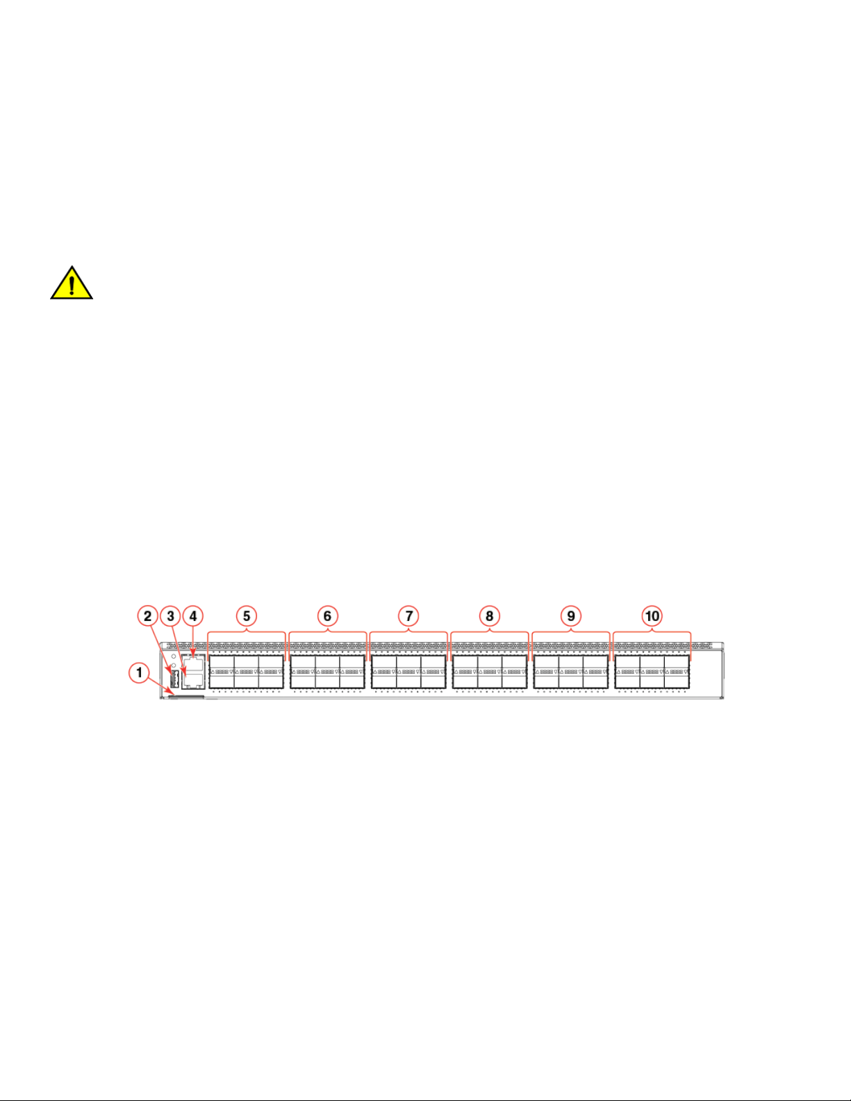
FIGURE 1 Port-side view of the Brocade VDX 6940-36Q
1. Switch ID pull-out tab
2. USB port
3. RJ-45 Ethernet management port
4. RJ-45 serial console port
5. 40 GbE QSFP ports 1-6
6. 40 GbE QSFP ports 7-12
7. 40 GbE QSFP ports 13-18
8. 40 GbE QSFP ports 19-24
9. 40 GbE QSFP ports 25-30
10. 40 GbE QSFP ports 31-36
20 53-1003495-06
Brocade VDX 6940 Hardware Installation Guide
Device Overview
Port-side view of VDX 6940-144S
The port side of the Brocade VDX 6940-144S includes the USB port, RJ-45 serial console and Ethernet management port, fixed 10
SFP+ ports, 40 GbE QSFP ports, and system status, power, and port operation LED indicators. Colored labels above and below ports
designate ports that belong to the same trunk group.
The following illustration shows device ports. Refer to LED locations on page 73 for details on port-side LED locations.
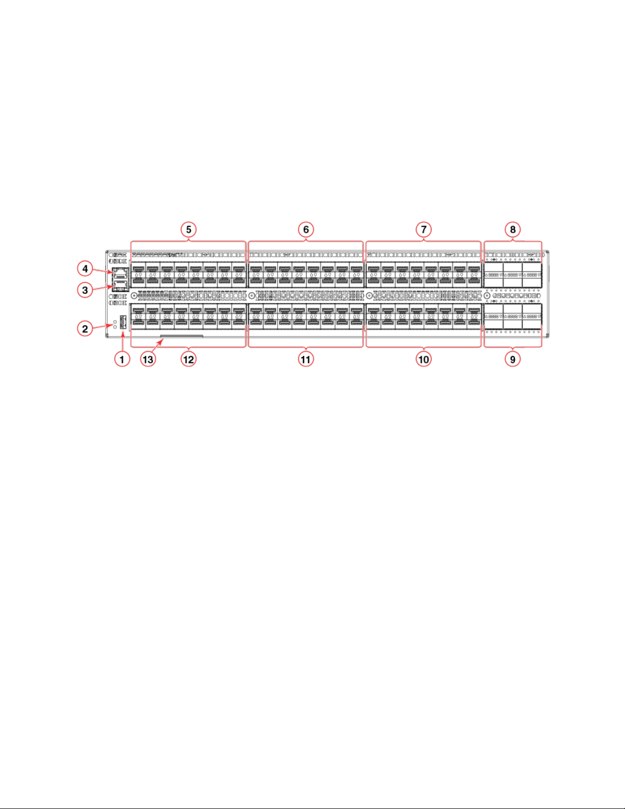
FIGURE 2 Port-side view of Brocade VDX 6940-144S
1. USB port
2. System and power status LEDs
3. RJ-45 serial console port
4. RJ-45 Ethernet management port
5. Fixed 10 GbE SFP+ ports 1-16
6. Fixed 10 GbE SFP+ ports 17-32
7. Fixed 10 GbE SFP+ ports 33-48
8. 40 GbE QSFP ports 97-102 *
9. 40 GbE QSFP ports 103-108*
10. Fixed 10 GbE SFP+ ports 81-96
11. Fixed 10 GbE SFP+ ports 65-80
12. Fixed 10 GbE SFP+ ports 49-64
13. Switch ID pull-out tab
NOTE
*Port 97, 98, 103, and 104 are dual-personality ports and can be configured for 100 GbE or 40 GbE operation. Refer to Dual
personality ports and port groups on page 27 for a diagram of 40 GbE and 100 GbE capable ports contained in dual-
personality port groups.
Brocade VDX 6940 Hardware Installation Guide
53-1003495-06 21
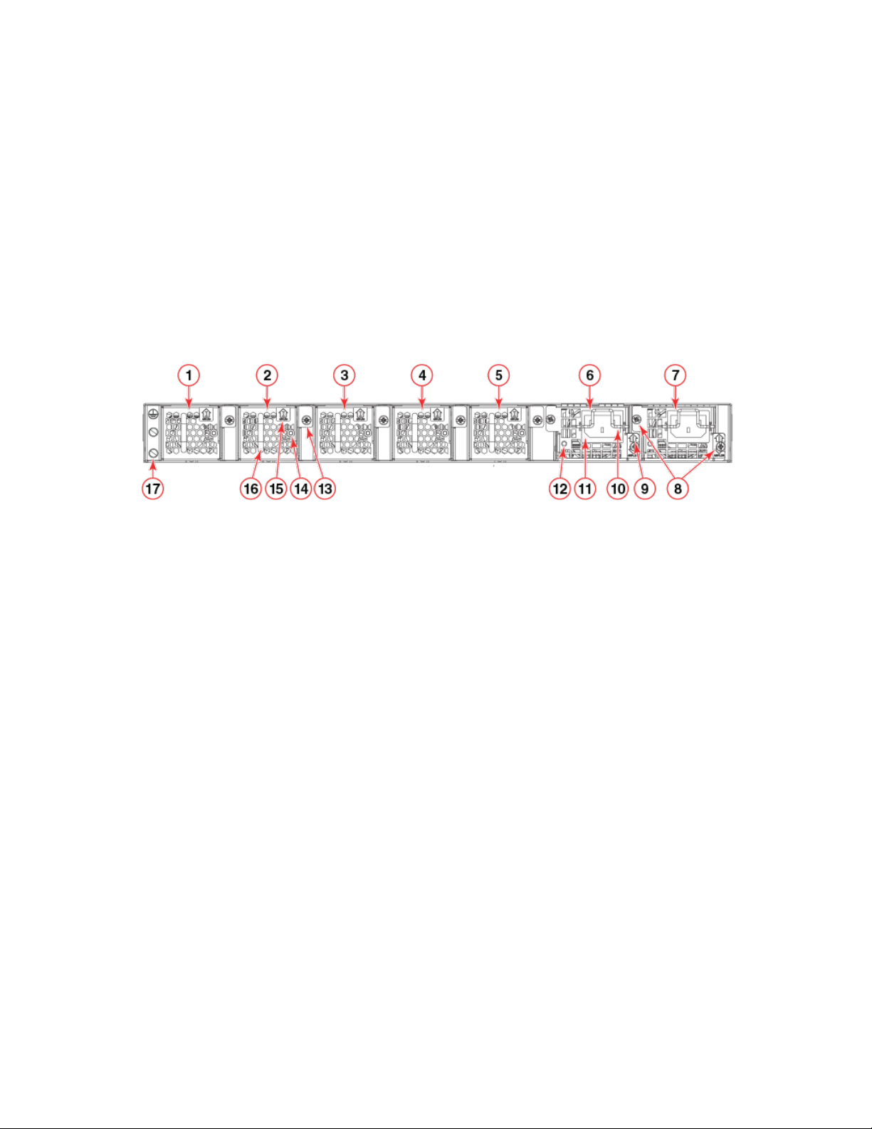
Device Overview
Non-port-side views
Use the following illustrations to locate fan assemblies, AC or DC power supplies, LED status indicators, and other components on
devices.
Non-port-side view of VDX 6940-36Q
The following illustration shows the fan assemblies, AC power supplies, and other components on the non-port side of the Brocade VDX
6940-36Q. Refer to LED locations on page 73 for details on LED locations.
FIGURE 3 Non-port-side view showing AC power supplies
1. Fan #1
2. Fan #2
3. Fan #3
4. Fan #4
5. Fan #5
6. Power supply #1
7. Power supply #2
8. Captive screws
9. Airflow label
10. Plug retainer
11. Plug receptacle
12. Status LED
13. Captive screw
14. Status LED
15. Airflow label
16. Handle
17. Ground lug attachment screws
The following illustration shows the fan assemblies, DC power supplies, and other components on the non-port side of the Brocade
VDX 6940-36Q. Refer to LED locations on page 73 for details on LED locations.
22 53-1003495-06
Brocade VDX 6940 Hardware Installation Guide
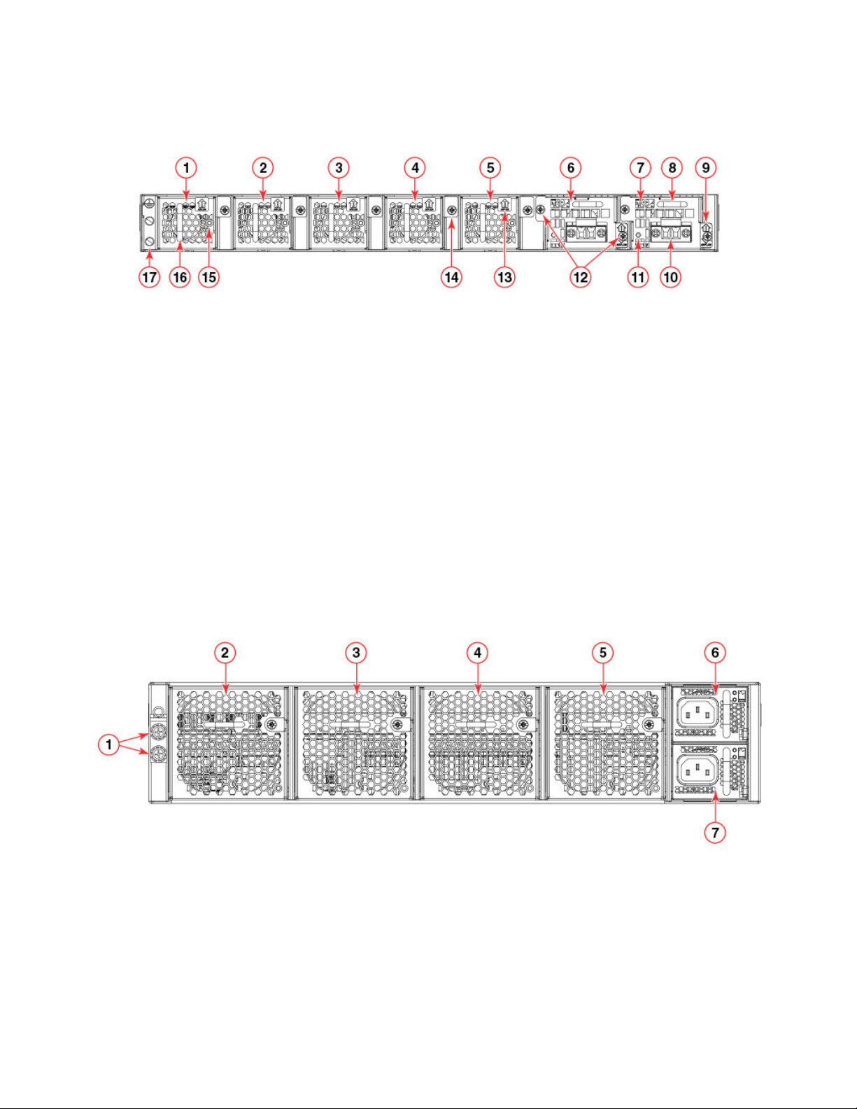
FIGURE 4 Non-port-side view showing DC power supplies
Device Overview
1. Fan #1
2. Fan #2
3. Fan #3
4. Fan #4
5. Fan #5
6. Power supply #1
7. Power supply #2
8. Handle
9. Airflow label
10. DC wire connectors
11. Status LED
12. Captive screws
13. Airflow label
14. Fan captive screw
15. Status LED
16. Handle
17. Ground lug attachment screws
Non-port-side view of VDX 6940-144S
The following illustration shows the fan assemblies, AC power supplies, and other components on the non-port side of the Brocade VDX
6940-144S. Refer to LED locations on page 73 for details on LED locations.
FIGURE 5 Non-port-side view showing AC power supplies
1. Ground lug attachment screws
2. Fan #1
3. Fan #2
4. Fan #3
5. Fan #4
6. AC power supply #1
7. AC power supply #2
Brocade VDX 6940 Hardware Installation Guide
53-1003495-06 23

The following illustration shows more detail of the AC power supplies and fans.
FIGURE 6 AC power supply and fan details
Device Overview
1. Fan captive screw
2. AC plug receptacle
3. Power supply handle
4. DC output status LED
5. AC input status LED
6. Power supply airflow label
7. Locking tab
8. Integral fan air inlet
9. Fan status LED
10. Fan handle
11. Fan airflow label
The following illustrations show the fan assemblies, DC power supplies, and other components on the non-port side of the Brocade
VDX 6940-144S. Refer to LED locations on page 73 for details on LED locations.
24 53-1003495-06
Brocade VDX 6940 Hardware Installation Guide
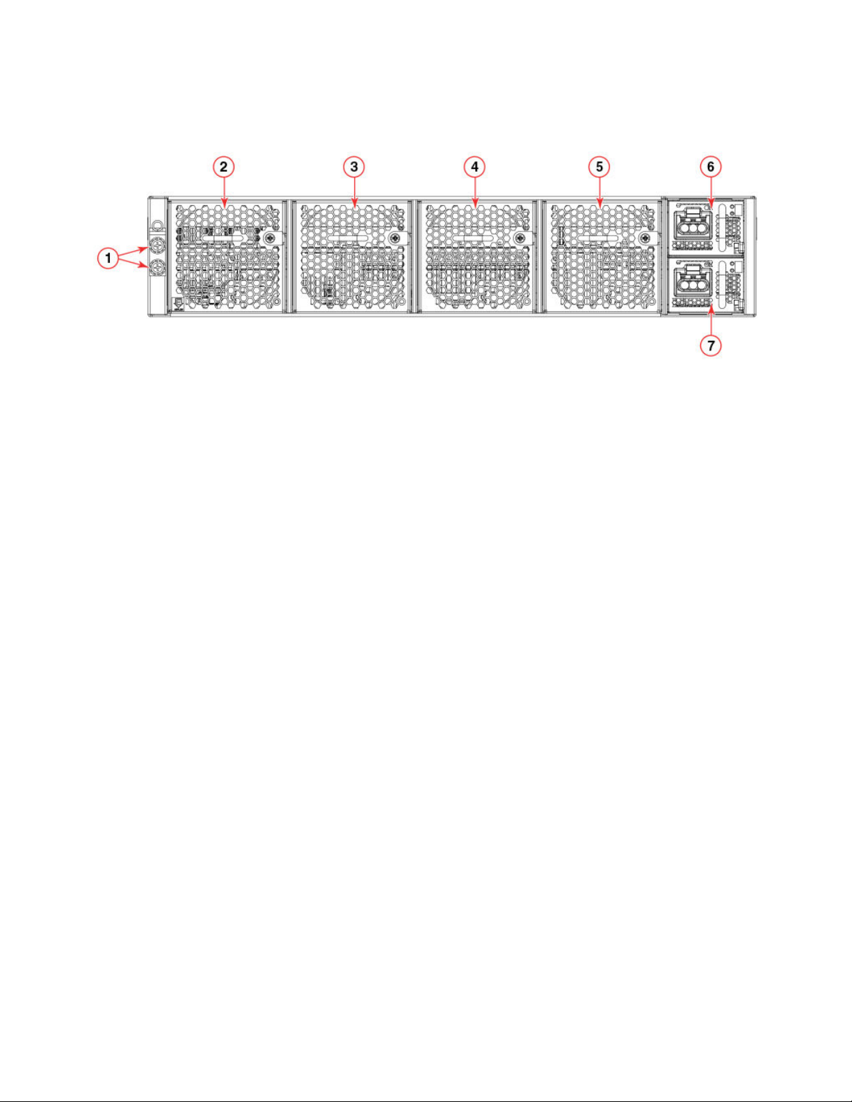
FIGURE 7 Non-port-side view showing DC power supplies
Device Overview
1. Ground lug attachment screws
2. Fan #1
3. Fan #2
4. Fan #3
5. Fan #4
6. DC power supply #1
7. DC power supply #2
The following illustration shows more detail of the fans and DC power supplies.
Brocade VDX 6940 Hardware Installation Guide
53-1003495-06 25
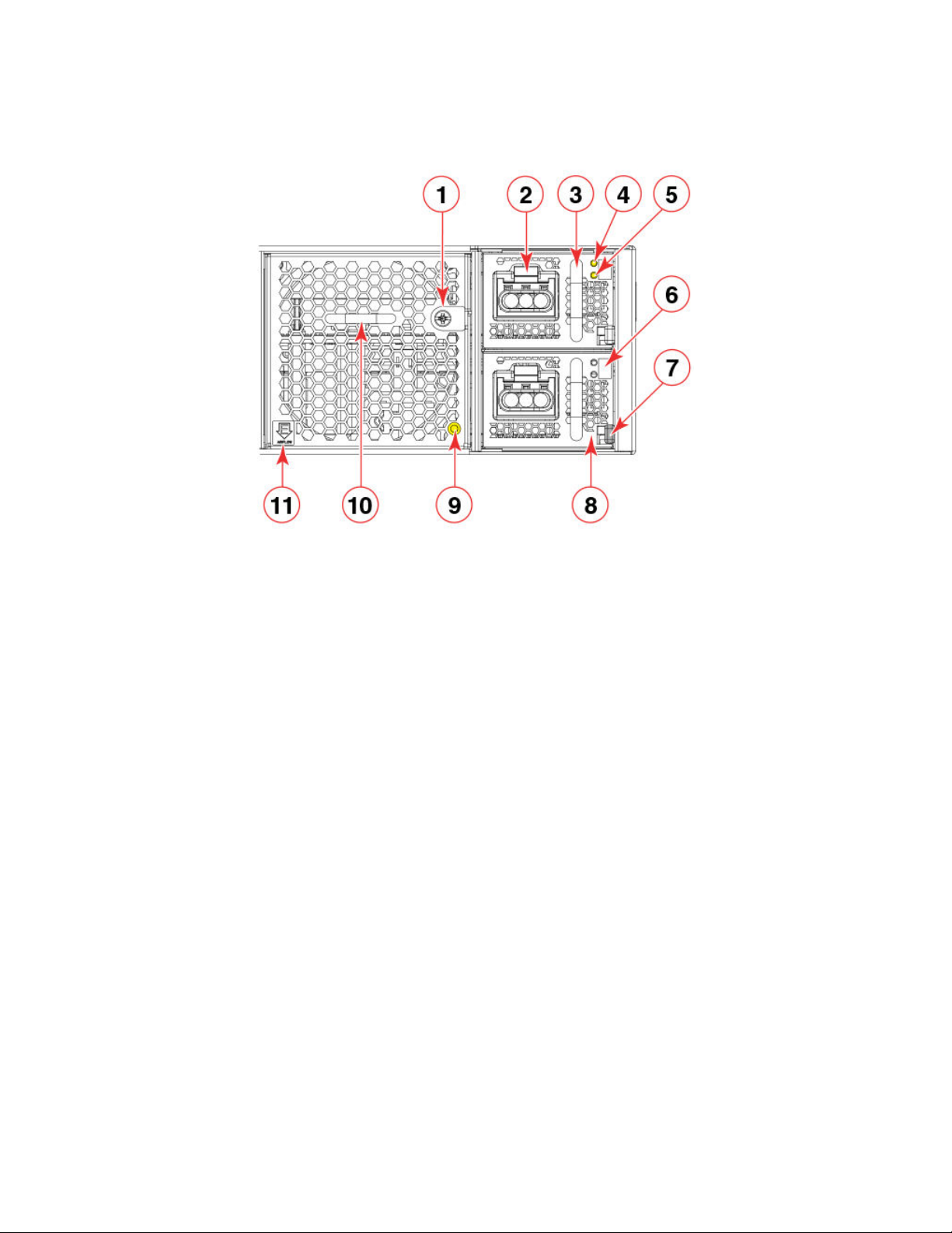
FIGURE 8 DC power supply and fan details
Device Overview
1. Fan captive screw
2. Power cable connector
3. Power supply handle
4. DC input status LED
5. DC output status LED
6. Power supply airflow label
7. Locking tab
8. Integral fan air inlet
9. Fan status LED
10. Fan handle
11. Fan airflow label
Port numbering
Port numbers for GbE ports are required for Network OS commands and management applications to configure connections and
features and determine port operation. Use the following illustrations to determine physical port numbering for Brocade VDX 6940
devices.
VDX 6940-36Q port numbering
For the Brocade VDX 6940-36Q, ports are numbered as follows:
∙ 40 GbE ports are numbered 1 through 36
∙ 10 GbE interfaces for the 40 GbE ports when in 4x10 GbE breakout mode are numbered X:1, X:2, X:3, and X:4, where X is the
40 GbE port number 1 through 36.
As shown in the following illustration, odd-numbered 40 GbE QSFP+ ports are on the top row and even-numbered ports are on the
bottom row.
26 53-1003495-06
Brocade VDX 6940 Hardware Installation Guide
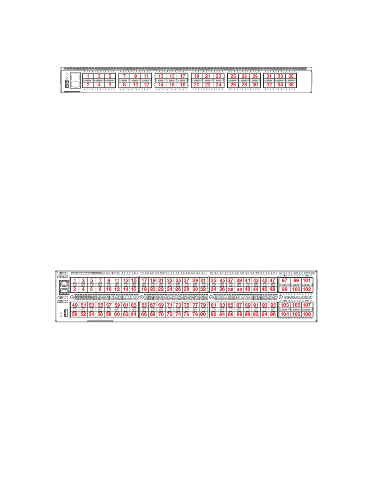
Device Overview
FIGURE 9 Brocade VDX 6940-36Q port numbering
A 40 GbE port configured in 4x10 GbE breakout mode creates four individual 10 GbE interfaces using the 40 GbE port number. For
example, four 10 GbE interfaces for port 36 are numbered as follows:
∙ 36:1
∙ 36:2
∙ 36:3
∙ 36:4
VDX 6940-144S port numbering
For the Brocade VDX 6940-144S, ports are numbered as follows:
∙ Fixed 10 GbE ports are numbered 1 through 96.
∙ 40 GbE ports are numbered 97 through 108.
As shown in the following illustration, the odd-numbered 10 GbE SFP+ and 40 GbE QSFP+ ports are on the top row and evennumbered ports are on the bottom row.
FIGURE 10 Brocade VDX 6940-144S port numbering
Dual personality ports and port groups
The following illustration shows the dual-personality ports and port groups on the Brocade VDX 6940-144S. Dual personality ports can
be configured as 40 GbE QSFP or 100 GbE QSFP28 ports with a qualified 40 GbE or 100 GbE transceiver installed. When a dual
personality port is configured for 100 GbE operation, the remaining 40 GbE ports in the same port group will be disabled. Ports 97, 98,
103, and 104 are dual personality ports.
Brocade VDX 6940 Hardware Installation Guide
53-1003495-06 27
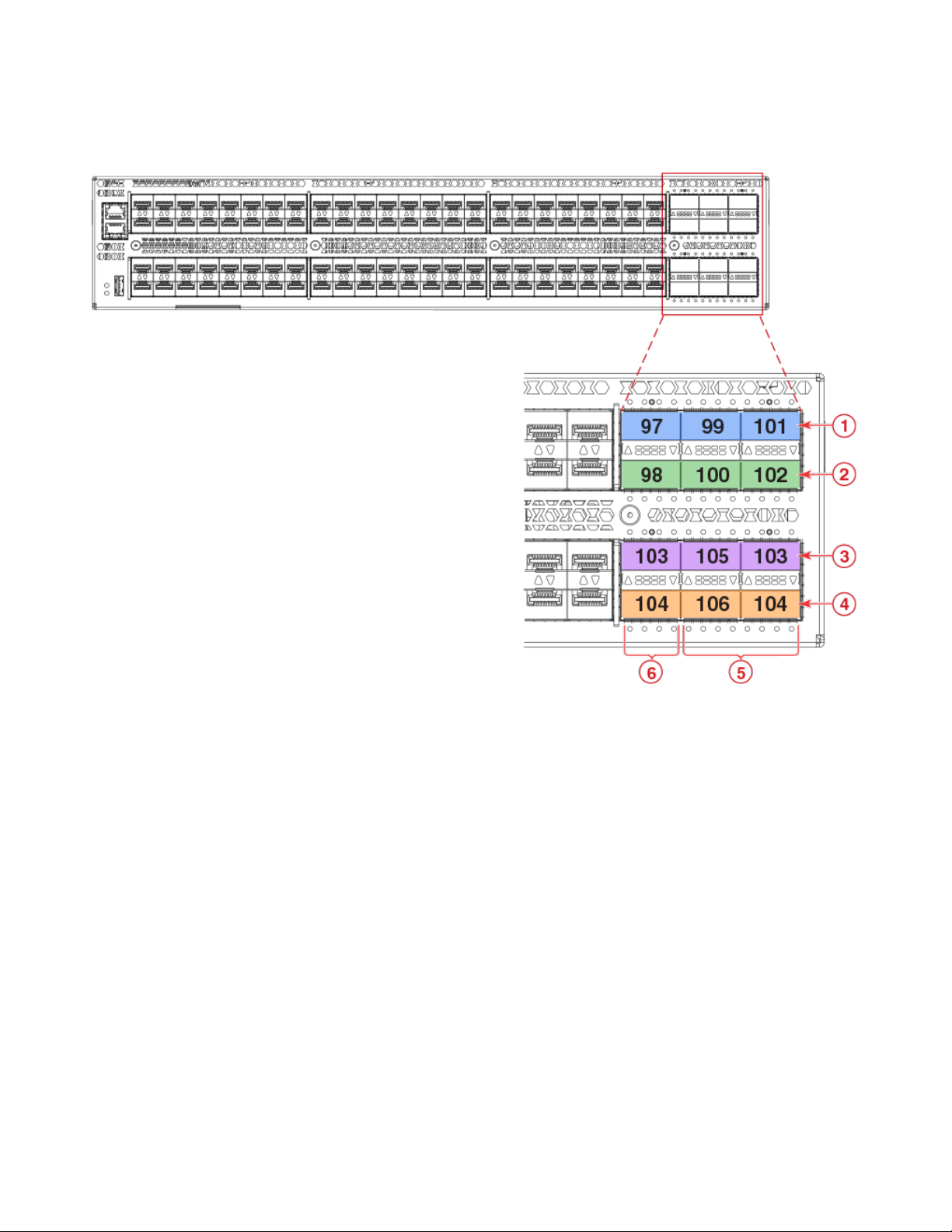
FIGURE 11 Dual -personality ports and port groups
Device Overview
1. Port group 1
2. Port group 2
3. Port group 3
28 53-1003495-06
4. Port group 4
5. 40 GbE ports
6. 100/40 GbE dual personality ports
Brocade VDX 6940 Hardware Installation Guide
Preparing for Installation
∙ Installation and safety considerations....................................................................................................................................................................29
∙ Items required for the installation...............................................................................................................................................................................31
∙ Items included with the device...................................................................................................................................................................................32
Installation and safety considerations
You can install this device in the following locations:
∙ In a four-post EIA rack
∙ In a two-post telecommunications (Telco) rack
∙ On a table top as a standalone device
Follow these precautions during installation:
CAUTION
Make sure the airflow around the front, sides, and back of the device is not restricted.
DANGER
The procedures in this manual are for qualified service personnel.
NOTE
It is strongly recommended that you review the Technical Specifications for this device before installation.
Power precautions
To install and operate the device successfully, ensure compliance with the following safety requirements:
∙ The power supply standards provided in the product Technical Specifications are met.
∙ The primary outlets are correctly wired, protected by a circuit breaker, and grounded in accordance with local electrical codes.
DANGER
Connect the power cord only to a grounded outlet.
∙ The supply circuit, line fusing, and wire size are adequate, as specified by the electrical rating on the device nameplate.
∙ This device might have more than one power cord. To reduce the risk of electric shock, disconnect both power cords before
servicing.
DANGER
Disconnect the power cord from all power sources to completely remove power from the device.
DANGER
This product is designed for an IT power system with phase-to-phase voltage of 230V. After operation of the protective device,
the equipment is still under voltage if it is connected to an IT power system.
Brocade VDX 6940 Hardware Installation Guide
53-1003495-06 29

Preparing for Installation
CAUTION
All devices with DC power supplies are intended for installation in restricted access areas only. A restricted access area is where
access can be gained only by service personnel through the use of a special tool, lock and key, or other means of security, and
is controlled by the authority responsible for the location.
DANGER
The intra-building port or ports of the equipment or subassembly is suitable for connection to intra-building or unexposed
wiring or cabling only. The intra-building port or ports of the equipment or subassembly MUST NOT be metallically connected
to interfaces that connect to the outside plant (OSP) or its wiring. These interfaces are designed for use as intra-building
interfaces only (Type 2 or Type 4 ports as described in GR-1089-CORE, Issue 5) and require isolation from the exposed OSP
cabling. The addition of Primary Protectors is not sufficient protection in order to connect these interfaces metallically to OSP
wiring.
CAUTION
The Brocade device must be connected to external Special Protection Devices (SPD) when installed and connected to
commercial AC power.
NOTE
The unit is suitable for installation as part of the Common Bonding Network (CBN).
For the 500W DC power supply used on the Brocade VDX 6940-36Q, use the following caution.
CAUTION
For the DC input circuit to the system, make sure there is a 20 Amp circuit breaker, minimum -48 VDC, double pole, on the
input terminal block to the power supply. The input wiring for connection to the product should be copper wire, 12 AWG,
marked VW-1, and rated minimum 90°C.
For the 1100W DC power supply used on the Brocade VDX 6940-144S, use the following caution.
CAUTION
For the DC input circuit to the system, make sure there is a 40-amp circuit breaker, minimum 60 VDC, double pole, on the
input to the terminal block. The input wiring for connection to the product should be copper wire, 8 AWG, marked VW-1, and
rated a minimum of 90 degrees celsius.
Environmental precautions
For successful installation and operation of the device, ensure that the following environmental requirements are met:
∙ Fans supplied with the device move air either front to back (exhaust) or back to front (intake). Be sure to align the device with the
airflow pattern of any other devices in the rack. All equipment in the rack should force air in the same direction to avoid intake of
exhaust air.
CAUTION
Ensure that the airflow direction of the power supply unit matches that of the installed fan tray. The power supplies and
fan trays are clearly labeled with either a green arrow with an "E", or an orange arrow with an "I."
∙ Ensure that the airflow available at intake vents allows the maximum airflow as specified in the product Technical Specifications.
∙ Ensure that the ambient air temperature does not exceed that specified for maximum operational temperate in the product
Technical Specifications.
30 53-1003495-06
Brocade VDX 6940 Hardware Installation Guide
 Loading...