

Page 1

®
SilkWorm
Hardware Reference Manual
2400
Publication Number 53-0001533-01
Page 2

Copyright
1998, 1999, Brocade Communications Systems, Incorporated.
ALL RIGHTS RESERVED. 53-0001533-01
BROCADE
registered trademarks of Brocade Communications Systems, Inc., in the United States and/or in other
countries.
All other brands, products, or service names are o r may be trademar ks or service marks of, and are used
to identify, products or services of their respective owners.
Notice: This document is for infor matio nal purposes only and does not set forth any warrant y , express
or implied, concerning any equipment, equipment feature, or service offered . BROCADE reserves the
right to make changes to this docu ment at any time, without notice, and assumes no respon sibility for
its use.
Export of technical data contained in this document may r equire an export license from the United States
Government.
Brocade Communications Systems, Incorporated
®
, SilkWorm®2400/2800, Fabric OSTMand the BROCADE logo are trademarks or
Page 3

Note Regarding Applicability of the Brocade®
SilkWorm®2400 Hardware Reference Manual
to Hewlett-Packard
Please be aware that the following updates apply to the SilkWorm 2400 Hardware Reference
Manual for Hewlett-Packard.
• Model numbers and part numbers are not applicable.
• Optional licensing information is not applicable.
• Notices, TOC, and Preface are applicable.
• Chapter 1 (Introduction) is applicable.
• Chapter 2 (Installation) is applicable, except for the following, which are not applicable:
- Option of one power supply
- Additional racking information available from Hewlett-Packard
• Chapter 3 (Diagnostics) is applicable.
• Appendix A (Specifications) is applicable. However, Table A should state that the operating
temperature is 10o to 30o, not 0o to 40o.
• Appendix B (Switch Support) is not applicable. Refer to your Hewlett-Packard support
contract for support information.
• Appendix C (Error Messages) is applicable.
A5625-96002
Copyright © 1999, 2000
Printed in USA 05/00
A5625-90902
Page 4

Page 5

NOTICES
FCC Warning (USA only)
This equipment has been tested and complies with the limits for a Class A computing device pursuant
to Part 15 of the FCC Rules. These limits are design ed to provide reason able protection against harmfu l
interference when equipment is operated in a commercial environment. This equi pment generates, uses,
and can radiate radio frequency energy and, if not installed and used in accordance with the instruction
manual, may cause harmful interference to radio communications. Operating this equipment in a
residential area is likely to cause harmful interference in which case the user is responsible for repairs.
VCCI Statement
This is a Class A product based on the standard of the Voluntary Control Council For Interference by
Information Technolog y Equipment (VC CI). If this equipment i s used in a domestic envi ronment, radio
disturbance may arise. When such trouble occurs, the user may be required to take corrective actions.
(Japanese Text)
CE Statement
The standards compliance label on the SilkWorm 2400 Fibre Channel Switch contains the CE mark
which indicates that this system conforms to the p rov isions of the following European Council
Directives, laws, and standards:
• Electro Magnetic Compatibility (EMC) Directive 89/336/EEC and the C omplementary
Directives 92/31/EEC and 93/68/EEC:
- EN550022, Class A; Emissions Industrial Environment
- EN 50082-2 Immunity Industrial Environment
- EN61000-4-2 Electro Static Discharge
- EN61000-4-3 Radiated RF
- EN61000-4-4 Electrical Fast Transients
- EN61000-4-5 Surge
- EN61000-4-6 Conducted RF
- EN61000-4-11 Line Interruption
• Low Voltage Directive (LVD) 73/23/EEC and the Complementary Directive 93/68/EEC:
- EN 60950:92 A1:93 & A2:93 & A3:95 & A4:96 & A11:97
- EN60825-1:199/A11, -2
Canadian Requirements
This class A digital apparatus meets all requirements of the Canadian Interference-Causing Equipment
Regulations.
Cet appareil numerique de la classe A respecte toutee les exigences du Regiements sur le material
brouilleur du Canada.
Laser Compliance
This equipment contains class 1 laser products, and it complies with FDA radiation Performance
Standards, 21 CFR Subchapter J.
Page 6

Page 7

CONTENTS 0
Preface
Chapter 1: Introduction
Switch Features . . . . . . . . . . . . . . . . . . . . . . . . . . . . . . . . . . . . . . . . . . . . 1-2
Performance . . . . . . . . . . . . . . . . . . . . . . . . . . . . . . . . . . . . . . . . . . . . 1-2
Manageability. . . . . . . . . . . . . . . . . . . . . . . . . . . . . . . . . . . . . . . . . . . 1-2
System Components. . . . . . . . . . . . . . . . . . . . . . . . . . . . . . . . . . . . . . . . . 1-3
Fabric Operating System . . . . . . . . . . . . . . . . . . . . . . . . . . . . . . . . . . 1-3
GBICs . . . . . . . . . . . . . . . . . . . . . . . . . . . . . . . . . . . . . . . . . . . . . . . . . 1-3
SWL Fiber-Optic GBIC Module . . . . . . . . . . . . . . . . . . . . . . . . . . . . 1-3
LWL Fiber-Optic GBIC Module. . . . . . . . . . . . . . . . . . . . . . . . . . 1-4
Passive Copper GBIC Module . . . . . . . . . . . . . . . . . . . . . . . . . . . 1-4
Chapter 2: Installation
Unpacking the Switch . . . . . . . . . . . . . . . . . . . . . . . . . . . . . . . . . . . . . . . 2-2
Cooling Requirements . . . . . . . . . . . . . . . . . . . . . . . . . . . . . . . . . . . . 2-2
Power Requirements. . . . . . . . . . . . . . . . . . . . . . . . . . . . . . . . . . . . . . 2-3
Site Location. . . . . . . . . . . . . . . . . . . . . . . . . . . . . . . . . . . . . . . . . . . . 2-3
Installation Considerations . . . . . . . . . . . . . . . . . . . . . . . . . . . . . . . . . 2-4
Rackmount Safety Guidelines. . . . . . . . . . . . . . . . . . . . . . . . . . . . 2-4
Installing Slide Assembly (Optional) . . . . . . . . . . . . . . . . . . . . . . 2-4
Standalone . . . . . . . . . . . . . . . . . . . . . . . . . . . . . . . . . . . . . . . . . . . 2-6
Fiber Channel Cable Connections . . . . . . . . . . . . . . . . . . . . . . . . . . . 2-6
Serial Port Connection . . . . . . . . . . . . . . . . . . . . . . . . . . . . . . . . . . . . 2-7
Serial Cabling and Emissions Requirements. . . . . . . . . . . . . . . . . 2-8
Setting IP Address using the Serial Port . . . . . . . . . . . . . . . . . . . . 2-9
Resetting Factory Defaults . . . . . . . . . . . . . . . . . . . . . . . . . . . . . . 2-9
Ethernet Connection . . . . . . . . . . . . . . . . . . . . . . . . . . . . . . . . . . . . . . 2-9
Verifying Power-On Self-Test (POST) . . . . . . . . . . . . . . . . . . . . . . 2-10
Chapter 3: Diagnostics
Diagnostic Overview . . . . . . . . . . . . . . . . . . . . . . . . . . . . . . . . . . . . . . . . 3-2
Verifying Power-On Self-Test (POST) . . . . . . . . . . . . . . . . . . . . . . . 3-2
Removing Power. . . . . . . . . . . . . . . . . . . . . . . . . . . . . . . . . . . . . . . . . 3-2
Diagnostic Commands. . . . . . . . . . . . . . . . . . . . . . . . . . . . . . . . . . . . . . . 3-3
Status and Activity Indicators . . . . . . . . . . . . . . . . . . . . . . . . . . . . . . . . . 3-4
Front Panel LED Port Indicators . . . . . . . . . . . . . . . . . . . . . . . . . . . . 3-4
Initialization Steps Summary . . . . . . . . . . . . . . . . . . . . . . . . . . . . . . . 3-5
Appendix A: Specifications
General Specifications. . . . . . . . . . . . . . . . . . . . . . . . . . . . . . . . . . . . . . .A-1
SilkWorm® 2400 Hardware Reference Manual vii
Page 8

Fabric Management Specifications . . . . . . . . . . . . . . . . . . . . . . . . . . . . .A-2
Safety Specifications . . . . . . . . . . . . . . . . . . . . . . . . . . . . . . . . . . . . . . . .A-2
Optical Port Specifications . . . . . . . . . . . . . . . . . . . . . . . . . . . . . . . . . . .A-3
Copper GBIC Module . . . . . . . . . . . . . . . . . . . . . . . . . . . . . . . . . . . . . . .A-3
Environmental Specifications . . . . . . . . . . . . . . . . . . . . . . . . . . . . . . . . .A-4
Dimensions. . . . . . . . . . . . . . . . . . . . . . . . . . . . . . . . . . . . . . . . . . . . .A-4
Rack Mount Dimensions. . . . . . . . . . . . . . . . . . . . . . . . . . . . . . . .A-4
Table Top Dimensions . . . . . . . . . . . . . . . . . . . . . . . . . . . . . . . . .A-4
Weight . . . . . . . . . . . . . . . . . . . . . . . . . . . . . . . . . . . . . . . . . . . . . .A-4
Power Supply. . . . . . . . . . . . . . . . . . . . . . . . . . . . . . . . . . . . . . . . . . . . . .A-5
Appendix B: Switch Support
Support Tool . . . . . . . . . . . . . . . . . . . . . . . . . . . . . . . . . . . . . . . . . . . . . .B-1
Appendix C: Error Messages
Chapter Index
viii
Page 9

PREFACE
The SilkWorm® 2400 Hardware Reference Manual describes how to use and maintain
the SilkWorm
Audience
The audience for this manual includes:
■ Field Technicians
How this Manual is Organized
The following table describes how the manual is organized.
2400 Switch.
FOR INFORMATION ON SEE
Switch features and system components Chapter 1,
Installing and setting up the switch Chapter 2,
Diagnostics Chapter 3,
Technical specifications Appendix A,
Customer support Appendix B,
SilkWorm 2400 Hardware Reference Manual ix
Introduction
Installation
Diagnostics
Specifications
Switch Support
Page 10

Preface
Related Publications
Other publications that may provide related information include:
■ Fabric OS Version 2.0 Manual, Part Number: 53-000 1555- 01
■ Fibre Channel Standards
For detailed information on the Fibre Channel standards, see the Fibre Channel
Association web site:
http://www.fibrechannel.com
Revision Histo r y
FABRIC OPERATING
S
YSTEM VERSION
2.o
2.0
2.0
2.0
2.0
2.0
2.0
DATE DOCUMENT
11/98
1/99
2/99
3/99
4/99
4/99
7/99
First Draft
Second Draft
Beta Draft
Beta 3 Draft
Final Draft
Released
Channel Update
x
Page 11
1
INTRODUCTION 1:
Port 0
Figure 1-1 Front Panel
SilkWorm 2400 is an 8-port Fibre Channel Gig abit Switch that consist s of a motherboard
with connectors for s upporting up to 8 ports, a nd fabric operating sys tem for building and
managing a Fabric. A Fabric is an active, intelligent, interconnect scheme for Fibre
Channel server and storag e nodes. Figure 1-1 shows the front vie w of the SilkWorm 2400
switch. Ports are numbered sequentially starting with zero for the left most port. The
switch face plate includes a silk screen imprint of the port number. Up to two power
supplies are suppor ted, t hese are s hown to the left a nd ri ght of the s witch por ts i n Figure
1-1. This chapter disc usses:
■ Features
■ System Components
WARNING SilkWorm 2400 contains two power supplies. To remove all power from the
system, disconnect both power supply cords.
Port 7
Power Supply #1Power Supply #2
SilkWorm 2400 Hardware Reference Manual 1-1
Page 12

Chapter 1 Introduction
Switch Features
The switch is a high-perfo rmance Fibre Channel Gigabit Switch with the follow ing
features:
■ Simple – Easy setup and con figurat ion. After Po wer-On Se lf-Test (POST), you
need only add th e switc h’s Internet Prot ocol (IP) ad dres s. Th e rema inde r of the
switch’s setup is autom ated .
■ Intelligent – The fabric operating system allows discovery of all connected
devices and determines optimum data paths without intervention, supporting up
to 239 interco nne ct ed sw itc he s.
■ Flexible – GBIC modules support fiber and copper transmission media. The
switch’s modular constructio n g ives the swit ch a r ange of fle xi bility in creat in g,
upgrading, maintaining, and configuring a Fabric.
■ Reliable – Hig hly in tegrat ed, re liab le, multif unct ion (AS IC) dev ices a re used
throughout the sw itch.
■ High performance – Low-latency, high-performance design requires no CPU data
path interactio n resulti ng in a worst ca se dat a transfe r late ncy o f less than two
microseconds from any port to any port at peak Fibre Channel bandwidth of 100
MB/sec. The latency may differ when the destination or device is a loop.
■ Automated congestion management – Virtual channels lets the swit ch use
sophisticated co nges tion ma nage ment te chniqu es th at are per form ed
automatically by the swit ch.
■ Cascading – You can casc ade swi tches for large Fab ric sup port. Up to 239
switches can be in terco nnecte d for a la rge Fabric w ith h undred s of Fabr ic
connections.
■ Compatibility – SilkWorm
2400 has been designed to inter-operate with the
SilkWorm 1000 series switches using a compatibility mode.
■ Universal – Switch po rts are d esigned t o support F, FL and E-p ort modes of ope ration
with the software selecting the optimum mode of operation.
Performance
A minimum aggregate r outin g cap acity o f 4,00 0,000 f rames/ sec is s pecif ied for Clas s 2,
Class 3, and Class F frames. Non-bl ocki ng t hroughput of up to 8 x 100MBytes/s ec (0.8
GBytes/sec) is provided.
A maximum switch late ncy of l ess than t wo micro seconds is specifi ed for Cl ass 2, Cl ass
3, and Class F frames when the output port is free.
Manageability
The unit may be managed in-band (using Fibre Channel protocol) or out-of-band via
connecting to the 10/100BaseT Ethernet port. Management interfaces include Telnet,
SNMP, SCSI Enclosure Services (SES), or a Web Tool.
1-2
Page 13

System Components
The motherboard is enclosed in an air-cool ed chassi s which ma y be eithe r mounted in a
standard rack or used as a standalone unit. The chassis includes one or two power
supplies, a fan tray , an RJ-45 Ethernet co nnection for switch se t up and management, and
a serial port. The serial port is used for recovering factory settings only and initial
configuration of the IP address for the switch if default address is not known.
Fabric Operating System
The fabric operating system is tuned for each installation. The system provides a large
number of commands and libraries to manage real time tasks.
GBICs
The switch accommodates up to eight GBIC modules. All interfaces have status lights
visible from the front panel giving a quick, visual check of the GBIC’s status and
activity.
System Components
GBIC modules supported are the ShortWave Length (SWL) and LongWave Length
(LWL) fiber-optics, and Copper (Cu) versions.
If your installation requires installing less than eight GBIC modules, the unused port
positions are protected by a metal, spring-loaded door.
SWL Fiber-Optic GBIC Module
The SWL fiber-optic GBIC module, with SC connector color-coded black, is based on
short wavelength lasers supporting 1.0625 Gbps link speeds. This GBIC module
supports 50-micron multi-mode fiber optic cables, with cables up to 500 meters in
length.The GBIC module is shipped with a protective plug in place and should remain in
place if no fiber optic cable is connected to the port. Figure 1-2 shows a GBIC module.
Figure 1-2 Short wavelength Laser (SWL) fiber optic GBIC module
The SWL GBIC module uses a Class 1 laser, which complies with the 21 CFR, subpart
(J) as of the date of manufacture.
SilkWorm 2400 Hardware Reference Manual 1-3
Page 14

Chapter 1 Introduction
LWL Fiber-Optic GBIC Module
The LWL fiber-optic GBIC module, with SC connector color-coded blue, is based on
long wavelength 1300 nm lasers support ing 1.0625 Gbps link spe eds. This GBIC module
supports 9-micron single-mode fiber. Cables up to 10 kilometers in length with a
maximum of five splices can be used. The GBIC module is shipped with a protective
plug in place and should remain in place if no fiber optic cable is connected to the port.
Figure 1-3 shows a GBIC module.
Figure 1-3 Long Wavelength Laser (LWL) fiber optic GBIC module
Passive Copper GBIC Module
The Copper (CU) GBIC module is based on the High-Speed Serial Data Connection
(HSSDC) interface standards. The GBIC provides a female HSSDC connector. Copper
cables up to 13 meters have currently been qualified, thereby supporting ANSI X3.230
FC-PH intra-cabinet requirements. Standard cables with HSSDC-to-DB9 male
connectors are also compatible. Figure 1-4 shows a passive copper GBIC.
Figure 1-4 Copper GBIC module
1-4
Page 15

2
INSTALLATION 2:
This chapter covers th e following:
■ Unpacking the sw itch
■ Selecting a location and mountin g method
■ Setting up connecti ons
SilkWorm 2400 Hardware Reference Manual 2-1
Page 16

Chapter 2 Installation
Unpacking the Switch
While unpacking the switch, check to make sure the following items are included:
■ Switch unit
■ Requested GBIC modules
■ Accessory kit containing the following:
■ Power cord, if ordered
■ Manuals, if ordered
■ Optional Software Feature Guides, if a feature(s) is ordered
■ Rubber mounting feet
Save packing materials in case you need to return the switch. Refer to Appendix B,
Switch Support for information on contacting Brocade.
Cooling Requirements
Cooling air is drawn into the chassis by six fans mounted near the rear of the chassis,
venting exhausted air through the front of the switch.
NOTE: Do not block the front or rear air vents. The switch must have
free access to ambient air for cooling.
2-2
Page 17

Unpacking the Switch
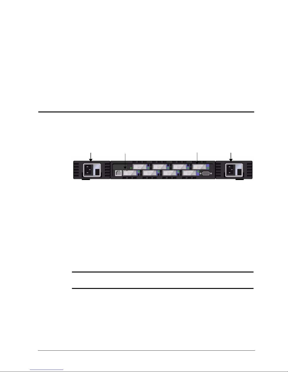
Power Requirements
Switch power connection is via two switche d connector s on the front pan el, as sho wn in
Figure 2-1. The switch power requirements are:
■ Properly wired, earth -groun ded ou tlet
■ Input voltage: 85 - 265 VAC
■ Total power: Up to 110 watts (depen ding on conf igurat ion, s ee App endix A,
Specification s)
■ Input line frequency: Nominally 47 to 63 Hz
The switch has an autoranging po wer supply that automatically accepts volta ges and line
frequencies within its ranges. A green power on indicator light is located above the
power switch in the power supply module.
NOTE: The SilkWorm
®
2400 is available in two models. The 2401
includes one power supply uni t and the 24 02 includes t wo power sup ply
units.
Power Supply 2
Figure 2-1 Model 2402 with Two Power Supplies
NOTE: The sw itch meets IE C 801- 5 surge voltag e requirements,
Power Supply 1
however, ther e is no ot her provis ion for surge pr otection buil t into the
switch’s power supplies. An installation should include normal
provisions to assure clean power.
Site Location
The switch should be installed in a secure or limited access site to control unauthorized
access to the switch’s cabling and power connections.
SilkWorm 2400 Hardware Reference Manual 2-3
Page 18

Chapter 2 Installation
Installation Considerations
The switch has optional mounting hardware to mount the switch in a standard 19-inch
rack.
Rackmount Safety Guidelines
In a rackmount installation, follow these safety guidelines:
■ When installi n g a switch in a clos ed or multi-rack assembly, make certain the air
■ Ensure that there is sufficient air flow availab le to th e switc h.
■ Verify that the switch installation, both with the slides closed and fully extended,
■ Verify the supply circuit, line fusi ng, and wire size ar e adequ ate. Re fer to the
■ Verify that all equipment installed in the rack has a reliable ground connection.
temperature, measured at the rack front, does not exceed 40° C during operation.
does not unbalance the rack or exceed the rack’s mechanical limits.
switch’s nameplate for its power requi rements.
Do not rely on connection to a branch circuit, such as power strips.
■ Route and support th e power cor d to ensure that the swit ch moves f reely on it s slides
without crimping or damaging the power cord or interfering with other equipment and
cabling installed in the rack.
Installing Slide Assembly (Optional)
Before starting switch slide installation and the switch rack installation, locate the rackmount slides and the mounting brackets package, then proceed:
To install slide assembly
1 Disassembl e the sli des by fully ext ending the s lide, pres sing the re lease, the n pulling
the slide apart.
2 Mount the sli de moving portion to each switch side as shown in Fi gure 2-2, using the
supplied slide screws.
3 Open the rack mounting package, and secure the four rack mounting attachments to
the stationary slide portion as shown in Figure 2-2.
4 Mount the two brackets using two screws (of the four provided) for each handle.
2-4
Page 19

Unpacking the Switch
Brackets are provided as part of the s li de kit . Th e br ac kets are used to secur e the swi tc h
to the rack. As shown in Figure 2-2, the two holes located towards the front of the switch
are used with the brackets. All the other holes are used for slide mounting.
Use brackets to attach switch to the rack here
Figure 2-2 Mounting the switch
1 Mount both stationary slide portions to the front and rear rack rails.
2 Engage the slide mounte d on the switc h with the sta tionary sli de portion mounted on
the rack, and press toward the rear until the latches engage.
3 Press the switch until the brackets are firmly seated on the rack front supports.
4 Secure th e swi tc h to the rack using the provided screws and nuts as shown in Figure
2-2.
5 Connect the switch to power. This completes the switch rack installation.
SilkWorm 2400 Hardware Reference Manual 2-5
Page 20

Chapter 2 Installation
Standalone
The switch is shipped in its st andal one conf igura tion. Adh esive r ubber f eet a re suppl ied
if the switch is surface mounted. Rubber feet installation is required for proper or safe
switch operation.
To install the adhesive rubber feet:
1 Clean the four depressions at each corner of the chassis bottom so that they are free
2 Remove the rubber feet from the sheet and place one in each depression.
3 Firmly press the rubber feet in place.
Fiber Channel Cable Connections
All network cable conne ctions a re to the switch’s fr ont panel . All recommen ded cablin g
supports the switch’s 1.0625-Gbps transfer rate, as shown in Table 2-1.
Table 2-1 Cabling Connections
of dust.
C
ABLE TYPE CABLE SPECIFICATION MAXIMUM
RUN LENGTH
SWL Fiber
a
Optic
LWL Fiber
a
Optic
Copper • Impedance controlled for
a. Recommend using a low EMI optical cable design.
• Duplex SC plug
connectors
• Multimode fiber
•50 µm core diameter
• 125 µm c ladding diameter
duplex cable
• Duplex SC plug
connectors
• Single mode fiber
•9 µm core diameter
• 125 µm c ladding diameter
duplex cable
150 ohm differential
systems
• Low skew, shielded quad,
150 ohm cable
• Polarized interface
• HSSDC receptacle
•500
meters
• 1641 feet
•10
Kilometers
• 84480 feet
•13 meters
• 42 feet
GBIC MODULE
OPTICAL
WAVELENGTH
780-860 µm
without open
fiber control
(non-OFC)
1270-1350 µm
without open
fiber control
(non-OFC)
NA
NOTE: The switch is not designed to interoperate with devices using
an Open Fibre Control optical interface.
2-6
Page 21

Unpacking the Switch
Fiber cable connectio ns are made to the swi tch’s front panel u sing standard dual SC plug
connectors as shown in Figure 2-3.
Figure 2-3 Dual SC fiber optic plug connector
The connectors are keyed and must be inserted into the GBIC module’s connector in
proper alignment. In most cases, one of the tw o connector plugs is a different color t o aid
in proper connector alignment.
NOTE: Remove the protective plug from the GBIC. Do not force the
fiber optic plug into the GBIC module as you may damage the
connector, the GBIC module, or both. Make certain the fiber surface
is clean, free of dust or debris, before inserting the connector into
GBIC module.
Copper cables use a High Speed Serial Data Connection (HSSDC) connector.
Serial Port Connection
The switch includes a serial port used to set the IP address when setting up or
reinitializing a switch. It is not us ed during nor mal operation. The setting s are as f ollows:
■ 8-bit
■ No parity
■ One stop bit
■ 9600 baud
SilkWorm 2400 Hardware Reference Manual 2-7
Page 22

Chapter 2 Installation
Figure 2-4 Connections
NOTE: The serial port and Telnet connection are mutually exclusive
and there can be only one serial port session active at a time. Telnet
takes priori ty, s o th e se ri al po rt is t er m inat ed wh en a Te ln et
connection is made. Th e serial connectio n is restored after the Tel ne t
session is completed but re-logging in is required. A password is
required to login to the serial port session as password checking is
skipped only at in it ia l pow e r on.
CAUTION The serial port is intended for initial configuration of the IP address or
Serial PortEthernet Port
disaster recovery only and not for regular maintenance.
Serial Cabling and Emissions Requirements
The switch uses a standard se rial cable with a male 9- pin D-Subminiature connec tor (but
only pins 2, 3 an d 5 are requir ed/supported; i f 7 is used, t his signal must a lways be driven
high, with the following pinouts:
Table 2-2 Cabling Pinouts
PIN S
1
2 TxData Transmit Data
3 RxData Receive Data
4
5 GND Logic Ground
6
7 CTS Clear to Send
8
9
IGNAL DESCRIPTION
NOTE: For dust and ESD protection, the switch includes a cover for
the serial port. When not in use, the serial port should be covered.
2-8
Page 23

Unpacking the Switch
Setting IP Address using the Serial Port
There is a label on the f ront panel of th e s witch with I P ADDRESS an d spac e to i nclude
the IP address when it is configured. This label facilitates identification of the physical
switch in main tenance mode.
The serial port is initially logged on as an “Admin” user.
To set IP Address using the Serial Port
1 Connect the serial port to a workstation using a standard serial cable with a DB9
connector.
2 Establish a connection to the shell.
The prompt is displayed as
For example: sw4:admin>
3 Enter the data to the ipAddrSet command (Fibre Channel IP address and subnet
mask and Ethernet IP address, subnet mask, and gateway address).
4 Copy the IP Address to the label provided for future reference.
switchName:userName>
Resetting Factory Defaults
In the event that a user changes a password and forgets it, the password can be
reinitialized.
To reset factory defaults
1 Connect t he s er ial po rt to a PC/ w orks ta ti on u si ng a sta nda rd serial cable with a DB9
connector.
2 Establish a connection to the shell.
The prompt is displayed as
For example: sw4:admin>
3 Enter the configDefault command. See the Fabric OS Manual for more
information.
switchName:userName>
Ethernet Connection
Connecting an existing Et hernet 10/100Ba seT LAN to the switch vi a the fr ont pan el RJ45 connector gives access to the switch’s internal SNMP agent and also allows remote
Telnet and Web access for remote monitoring and testing.
NOTE: The connection is only for Telnet, SNMP agent and the Web-
based Server access. No Fabric connection is used via this connection.
SilkWorm 2400 Hardware Reference Manual 2-9
Page 24

Chapter 2 Installation
Verifying Power-On Self-Test (POST)
The following table lists the diagnostic tests automatically run during POST.
Table 2-3 POST Tests
TEST BRIEF DESCRIPTION
Memory Test Checks CPU RAM memory.
Port Register Test Checks the ASIC registers & SRAMs.
Central Memory Test Checks the motherboard SRAMs.
Port Loopback Test Checks all of the switch’s hardware:
POST behaves differently depending on the boot method. A power cycle (power off &
power on) is consid ered a cold boot. All other boots fro m a powered-on stat e (per reboot,
panic, etc.) are considered warm boots.
POST execution per cold boot executes the long version of Memory Test. POST
execution per warm boot executes a shorter version of Memory Test. Boot time with
POST varies depending on the boot method.
frames transmitted, are looped back, and received
As the POST successfully perf orms each of the t ests, a message, “
Passed,” is displayed
via the Telne t.
After the switch compl et es the POST, the por t module returns to a st eady state from the
flashing states shown during the tests.
If a yellow port mod ule light is d isplayed or i s slowly flash ing, this ind icates that t he port
is in a failed state and diagnostic output should be examined to determine the source of
failure.[ See Table 3-2 for other light indications.]
If error conditions are encountered, they can be displayed via Telnet after the switch
completes the POST.
2-10
Page 25

3
DIAGNOSTICS 3:
This chapter discusse s trouble shooting, a nd diagnost ic testing. I t includes t hese secti ons:
■ Diagnostic Overview
■ Diagnostic Command Summary
■ Status and Act ivi ty Ind ic ators
SilkWorm 2400 Hardware Reference Manual 3-1
Page 26

Chapter 3 Diagnostics
Diagnostic Overview
The switch is designed for maintenance free op eration. When the re is a suspected fai lure,
the switch has self diagnostic capabilities to aid in isolating any equipment or Fabric
failures.
The switch supports Power-On Self-Tests (POSTs) and diagnostic tests. The diagnostic
tests determine the switch’s status and isolates problems and are run via telnet
commands. For more information on diagnostic testing commands and procedures, see
the Fabric Operating System Version 2.0 Manual.
Verifying Power-On Self-Test (POST)
When powering on a switch, the switch conducts a series of diagnostic tests including:
■ Dynamic RAM Test
■ Port Register Test
■ Central Memory Test
■ CMI Connector Test
■ CAM Test
■ Port Loop Back Test
Should the switch f ail to complete POST succe ssf ul ly, the green power LED wi ll be set
to blink. This is an indication of a fault in one of the initial stages of POST and indicates
that the CPU is not able to bring up the operating environment. Should this condition
occur, the switch should be returned for repair.
If a serial link is connected to the SilkWorm 2400 switch on initial power up, the switch
type will be printed t o the terminal scree n, followed by the mess age ‘Starting RAM te st’.
On completion of the RAM test, the OS is loaded into CPU memory and the operating
environment is then booted. (A RAM test failure will result in the power LED to blink).
If the switch c an compl etel y boot th e oper ating sy stem, bu t o ther error s are en counte red
during POST, these errors will be logged in the system error log. A Telnet session or
serial link connec ti on t o the switch will enabl e vi ewing of the error log. [S ee t he Fabric
OS Reference Manual diagnosti c and telne t commands for a descr iptio n of the errSh ow
command and details on running diagnostics.]
Removing Power
NOTE: Error messages are stored in RAM and are lost when power is
removed from th e sw itc h. A c cess th e e rror m essa g e l og to vi ew a nd
note any erro r me ss age s b e fore re mov in g pow er from t he sw it ch.
3-2
Page 27

Diagnostic Commands
The following tests are available from the switch’s Telnet connection:
■ Switch Offline (switchDisable)
■ Memory Test (ramTest)
■ Port Register Test (portRegTest)
■ Central Memory Test (centralMemoryTest)
■ CMI Conn Test (cmiTest)
■ CAM Test (camTest)
■ Port Loopback Test (portLoopbackTest)
■ Cross Port Test (crossPortTest)
■ Spin Silk Test (spinSilk)
■ SRAM Data Retenti on Test (sramRetentionTest)
■ CMem Data Retention Test (cmemRetentionTest)
Diagnostic Commands
■ Switch Online (switchEnable)
Table 3-1 Offline and Online Test
FFLINE TESTS OFFLINE & ONLINE TESTS
O
portRegTest ramTest
centralMemoryTest crossPortTest
cmiTest
sramRetentionTest
cmemRetentionTest
camTest
portLoopbackTest
spinSilk
See the Fabric Operating System Reference Manual for the usage of these test
diagnostics.
SilkWorm 2400 Hardware Reference Manual 3-3
Page 28

Chapter 3 Diagnostics
Status and Activity Indicators
Front Panel LED Port Indicators
The color and flash speed of each port’s LED, as described in Table 3-2, indicates the
individual port’s status.
Table 3-2 Front Panel LED Status Indicators
RONT PANEL LEDS DEFINITION
F
No light showing No light or signal carrier (no module, no cable) for media interface
Steady yellow Receiving light or signal carrier, but not yet online
Slow* yellow Disabled (result of diagnostics or portDisable command). Flashes
Fast* yellow Error, fault with port. Flashes every 1/2 second.
Steady green Online (connected with device over cable)
Slow green Online, but segmented (loopback cable or incompatible switch) flash
Fast green Internal loopback (diagnostic). Flashes every 1/2 second.
Flickering green Online and frames flowing through port.
* Slow -- 2 second interval, Fast - 1/2 secon d interval
LEDs
every 2 seconds.
every 2 seconds.
Each switch port includes an LED indicator. A port with no GBIC installed that if
functioning properly will have no light showing on the LED. If a problem has been
detected with the port, the LED i ndicators above wi ll provide so me indication o f the type
of problem. Faults and problems are depicted with a yellow port indicator.
When a GBIC is installed and a cable is connected to a properly functioning Fibre
Channel device, the LED indica tor will be steady green. If a slow green fla sh is observed
it indicates t he port is seeing light but cannot make a proper fab ric connection. Thi s could
indicate a loopback cable is installed, the fabric is segmented (a E port connection to
another switch cannot be completed and the switches cannot form a fabric), or the
SilkWorm h as been connected to an incompatible switch.
When frame traffic is being transferred on a port, the LED flickers fast green showing
the port is active and transferring data.
3-4
Page 29

Status and Activity Indicators
Initialization Steps Summary
At power-on or reset, the following steps are executed:
1 Preliminary POST diagnostics
2 VxWorks operating s ystem initia lization
3 Hardware initiali zation (resets, internal addresses assigned to ASICs, serial po rt
initialized, front panel initialized)
4 Full POST
5 Universal Port configuration.
6 Link initialization; receiver/transmitter negotiation to bring connected ports online
7 Fabric analysis; the switch checks for ports connected to other Fabric elements. If
there are other Fabric elements connected, it identifies the master switch.
8 Address assignment; after the master switch is identified, port addresses may be
assigned. Each switch tries to keep the same addresses that were previously used.
These are stored in the switch’s configuration flash PROM.
9 Routing table constru ction; af ter addresses are assigne d, the unicast routing tabl es are
constructed.
10 Enable normal port operation.
SilkWorm 2400 Hardware Reference Manual 3-5
Page 30

Chapter 3 Diagnostics
3-6
Page 31

A
SPECIFICATIONS A:
General Specifications
Table A-1 shows the switch specifications.
Table A-1 Switch Specifications
PECIFICATIONS DESCRIPTION
S
ANSI Fibre Channel protocol Fibre Channel ANSI Standard (FC-PH)
Fabric Initialization Complies with FC-SW 3.2
IP Over Fibre Channel (FC-IP) Complies with 2.3 of the FCA profile
System architecture Nonblocking shared-memory switch
System processor Superscalar 33-Mhz Intel i960RP
Number of Fibre Cha nnel Ports 8 port s
Fibre Channel port speed 1.0625 Gbps full duplex
Modes of operation Fibre Channel Class-2 service and Fibre Channel Class-3
Aggregate switch I/O
bandwidth
Frame buffers 16 buffers per port at 2112 bytes per frame
Fabric latency <2 microseconds with no contention
Data transmission range Up to 500 m (1,625 ft.) for short-wavelength optical link
Chassis types Back-to-front airflow (power supply out front)
SilkWorm 2400 Hardware Reference Manual A-1
connectionless service
8 Gbps, full duplex
Up to 10 kilometers (84,480 ft.) for long-w avel ength opt ical link
Page 32

Appendix
Fabric Management Specifications
Table A-2 shows Fabric management specifications:
Table A-2 Fabric Management Specifications
TANDARD FEATURES DESCRIPTION
S
Fabric management Simple Name Server, Alias Server, SNMP, Telnet, World Wide
User interface RJ45 front panel connector for 10/100Base-T Ethernet or in-
Serial port Local front panel RS-232 port for recovering factory settings
Web
band
Safety Specifications
Table A-3 shows Fabric management specifications:
Table A-3
OUNTRY SAFETY EMC
C
Canada CSA 22.2 No. 950 Third
United States UL 1950 Third Edition FCC Part 15 Class A
Japan EN60950+A1+A2+A3+A4+
International EN60950+A1+A2+A3+A4+
Safety Specifications
Edition
A11
A11
CSA C108.8 Class A
VCCI Class A
EN55022 Level A/
CISPR22 Class A
United Kingdom/
Ireland
France EN60950+A1+A2+A3+A4+
Germany EN60950+A1+A2+A3+A4+
Austria EN60950+A1+A2+A3+A4+
Spain/Portugal/Italy EN60950+A1+A2+A3+A4+
Sweden EN60950+A1+A2+A3+A4+
Norway EN60950+A1+A2+A3+A4+
A-2
EN60950+A1+A2+A3+A4+
A1 1;73/2 3/EEC
A11;73/23/EEC
A11;73/23/EEC
A11;73/23/EEC
A11;73/23/EEC
A11;73/23/EEC
A11
EN55022 Level A;
89/336/EEC
EN55022 Level A;
89/336/EEC
EN55022 Level A;
89/336/EEC
EN55022 Level A;
89/336/EEC
EN55022 Level A;
89/336/EEC
EN55022 Level A;
89/336/EEC
Page 33

Optical Port Specifications
Table A-3
OUNTRY SAFETY EMC
C
Finland EN60950+A1+A2+A3+A4+
Denmark EN60950+A1+A2+A3+A4+
Australia AS/NZS 3548:1995 Class A
New Zealand AS/NZS 3548:1995 Class A
Safety Specifications(Continued)
A1 1;73/23/EEC
A11;73/23/EEC
Optical Port Specifications
Fibre Channel interfaces of a SilkWorm 2400 system equipped with an optical port
interface uses a sho rtwave (78 0 to 850 nm.) or long wav elength (1270 to 1350 n m) laser
transmitter. The laser c omplies wi th 21 CFR( J) Clas s 1 la ser saf ety req uirements . It us es
Non-Open F ibre Contr ol (OFC) Optical GBICs in the switch circuit. Safe Class 1
operation is guaranteed by limiting optical power emitted by the port, thereby
eliminating the need for physical shutters. The optical GBIC uses the duplex-SC
connector scheme.
EN55022 Level A;
89/336/EEC
EN55022 Level A;
89/336/EEC
Copper GBIC Module
The Copper (CU) GBIC module is based on the High-Speed Serial Data Connection
(HSSDC) interface standards. The GBIC provides a female HSSDC connector. Copper
cables up to 13 meters have currently been qualified, thereby supporting ANSI X3.230
FC-PH intra-cabinet requirements. Standard cables with HSSDC-to-DB9 male
connectors are also available.
SilkWorm 2400 Hardware Reference Manual A-3
Page 34

Appendix
Environmental Specifications
The SilkWorm 2400 switch’s pr imary operating environments are server rooms, network
equipment closets, and office environments. Th e acceptable environment al r ange s for a
SilkWorm switch are shown in Table A-4:
Table A-4 SilkWorm 2400 Environmental Specifications
Specification Value
Temperature (ope rati ng) 0°
Temperature (non -op erati ng ) -35°
Operating humidity 5% to 85% noncondensing @ 40°
Nonoperating humidity 95% RH noncondensing @ 40°
Operating Altitude 0 to 3 kilometers above sea level
Nonoperating Altitude 0 to 12 kilometers above sea level
Operating shock 5g, 11MS duration, half sine
Nonoperating shock 20g, 11MS duration, sq.wave
Operating vibration 5, 5-500-5Hz@1.0 octave/minute
Nonoperating vibration 10, 5-500-5Hz@1.0 octave/minute
Handling drop
C to 40 °C
C to 65 °C
C
C
Dimensions
The switch may be configured for either rack mount or tabletop use.
Rack Mount Dimensions
1U, 19-in. rack mount (EIA compliant)
H: mm (1.71 in.), W: 428.6 mm (16.88 in.), D: 450.0 mm (17.72 in.)
Table Top Dimensions
H: 43.4 mm (1.86 in.), W: 428.6 mm (16.88 in.), D: 450.0 mm (17.72 in.)
Weight
17 lbs.
A-4
Page 35

Power Supply
The SilkWorm 2400 has a universal power supply capable of functioning worldwide
without volt age jumpers or switches. The supply is autoranging in terms of
accommodating input voltages and line frequencies.
The power supply meets the following requirements:
Table A-5 Power Supply Requirements
Total power 110 watts
Input voltage 85 to 265 VAC
Input line frequency 47 to 63 Hz.
Inrush Current 10 Amps Peak, > 300 usec - hot/cold start
Harmonic Distortion Active power factor correction per IEC1000-3-2
Input Line Protection Fused in both hot & neutra l lines
Power Supply
Maximum Dime ns ions 3.5”W X 1.5”H X 11”L
Redundancy Dual Supplies - Hot Pluggable
BTU Rating 110 watts X 3.412 BTU/hr/watts = 375 BTU/hr
The power supply has a modular design that plug s directly into the enclosure throu gh the
front panel, mating to an internal blind-mate connector. It provides facilities to support
a dual redundandant power supply configuration in which the supplies are hotswappable.
An integral on/off switch, input filter and power indicator are provided in the power
supply.
SilkWorm 2400 Hardware Reference Manual A-5
Page 36

Appendix
A-6
Page 37

B
SWITCH SUPPORT B:
Support for your switch ca n be obtaine d from the supplier of your switch. Pl ease cont act
the supplier to report hardware or software problems. The supplier is also the correct
source for switch repairs or for supplying spare components.
Support Tool
Included in the switch software is a command that will provide a display of a variety of
information that is helpful in diagnosing switch related problems. This command is:
suppportShow. This comma nd can be entered into a telne t session command window and
the results should be saved and supplied to your support contact.
SilkWorm 2800 Hardware Reference Manual B-1
Page 38

Appendix
B-2
Page 39

C
ERROR MESSAGES C:
This appendix explains the error message format and possible errors.
There is one error message fo rmat for the swit ch whethe r you are gathe ring i nformat ion
from the local RS-232 serial port or using a remote Telnet session.
In all cases, the last err or encount ered is the first error displ ayed. Up to 64 mess ages are
held in a buffer. If the 64 message limit is exceeded, the messages are overwritten in a
first in, first out sequence.
errShow command displays all detected errors. The output provides additional
The
information over the front panel display. The following information is displayed in
Figure E-1:
■ There are two errors which have been detected.
■ The task ID and task name that incurre d th e er ror (task name are d is played using the
i command).
■ The error type, date and time, the error level, and description.
■ If there is more than one occurrence of an error type, the number of occurrences is
shown in brackets following the date and timestamp.
NOTE: The error counter goes to a maximum of 999.
SilkWorm 2400 Hardware Reference Man ual C-1
Page 40

Appendix
The display halt s after each e rr or i s displayed, prompt ing you to eithe r press <Enter> to
continue or type a
Q to quit. Continue pressing <Enter> until the prompt (=>) is
displayed.
switch:admin> errShow
Date & Time of
Occurences
Number of Occurences
Error 02
--------
Task ID
Task Name
0x103dc470 (tSwitch): Apr 9 10:41:06 (4)
Error SENSOR-FAILED, 3, sensor 7 (Fan 2) is below minimum
Type <CR> to continue, Q<CR> to stop:
Error Type
Error 01
-------0x103dc470 (tSwitch): Apr 9 10:40:51
Error DIAG-TIMEOUT, 1,
Port 2 receive timeout.
Error Level
Description
Err#0004
Type <CR> to continue, Q<CR> to stop:
Figure E-1 errShow Command Example
To display error messages via Telnet
1 From the prompt, enter errShow command.
2 To scroll through the error list, type <CR>
3 Scroll thr oug h er ror l og ( if no e rr ors enc ount er ed, the command returns “No Er ro r”) .
C-2
Page 41

INDEX
C
complete installation 2-1
components, system 1-3
connections
ethernet
fibre optic cable 2-6
serial port 2-7
cooling requirements 2-2
2-9
setting address
2-9
L
LEDs
flash speed and color
green 3-4
yellow 3-4
link initialization 3-5
M
managing SilkWorm
via front panel buttons
3-4
x
D
diagnostics 3-2
dimensions
rackmount
table top A-4
A-4
E
ethernet connections 2-9
F
features 1-2
fiber optic cable connections 2-6
fibre channel protocol A-1
G
GBIC module 1-3, 1-4
I
initialization 3-5
installation
attaching rubber feet
complete install 2-1
cooling requirements 2-2
power requirements 2-3
rackmount considerations 2-4
site location 2-3
unpacking the switch 2-2
introduction 1-1
ipAddrSet command
2-6
O
operating system 3-5
P
POST 3-5
power requirements 2-3
R
rackmount installation 2-4
requirements
cooling
power 2-3
2-2
S
serial port
cabling
pinouts 2-8
setting IP Address 2-9
specifications A-1
system components 1-3
2-8
V
VxWorks 3-5
SilkWorm 2400 Hardware Reference Manual Index-1
Page 42

Index
Index-2
 Loading...