

Page 1

Brocade SilkWorm 12000
Design, Deployment and
Management Guide
Publication Number 53-0000251-02
Page 2

Copyright ©2002, Brocade Communications Systems, Incorporated.
ALL RIGHTS RESERVED. Publication Number 53-0000251-02
BROCADE, the Brocade B weave logo, Brocade: the Intelligent Platform for Networking Storage, SilkWorm, and
SilkWorm Express, are trademarks or registered trademarks of Brocade Communications Systems, Inc. or its
subsidiaries in the United States and/or in other countries. All other brands, products, or service names are or may be
trademarks or service marks of, and are used to identify, products or services of their respective owners.
Notice: This book was designed and written to provide information about storage area networking architectures. Every
effort has been made to make this book as complete and accurate as possible. However, the information in this book is
provided to you “AS IS,” without warranty of any kind, including, without limitation, any implied warranty of
merchantability, noninfringement or fitness for a particular p urpose. Disclosure of information in this material in no way
grants a recipient any rights under Brocade's patents, copyrights, trade secrets or other intellectual property rights.
Brocade reserves the right to make changes to this docume nt at any time, without notice, and assumes no responsibility
for its use.
IMPORTANT NOTICE
This document is the property of Brocade. This document is confidential to Brocade. It is inte nded solely as an aid for
installing and configuring Storage Area Networks constructed with Brocade switches. This document does not provide a
warranty to any Brocade software, equipment, or service, nor does it imply product availability. Brocade is not
responsible for the use of this document and does not guarantee the results of its use. Brocade does not warrant or
guarantee that anyone will be able to recreate or achieve the results described in this document. The installation and
configuration described in this document made use of third party software and hardware. Brocade does not make any
warranties or guarantees concerning such third party software and hardware.
The authors and Brocade Communications Systems, Inc. shall have no liability or responsibility to any person or entity
with respect to any loss, cost, liability or damages arising from the information contained in this book or the computer
programs that accompany it.
Export of technical data contained in this document may require an export license from the United States Government.
Brocade Communications Systems,
Incorporated
Corporate Headquarters
1745 Technology Drive
San Jose, CA 95110
T: (408) 487-8000
F: (408) 487-8101
European Headquarters
29, route de l-Aeroport
Case Postale 105
1211 Geneva 15,
Switzerland
T: +41 22 799 56 40
F: +41 22 799 56 41
europe-info@brocade.com
Asia-Pacific Headquarters
The Imperial Tower 15th Floor
1-1-1 Uchisaiwaicho
Chiyoda-ku, Tokyo 100-0011
Japan
T: +81 33507 5802
F: +81 33507 5900
apac-info@brocade.com
Page 3

Contents
Preface
Introduction . . . . . . . . . . . . . . . . . . . . . . . . . . . . . . . . . . . . . . . . . . . . . . . . . . vii
Audience for This Document . . . . . . . . . . . . . . . . . . . . . . . . . . . . . . . . . . . . . vii
References . . . . . . . . . . . . . . . . . . . . . . . . . . . . . . . . . . . . . . . . . . . . . . . . . . . vii
Chapter 1 Introducing the SilkWorm 12000
Hardware . . . . . . . . . . . . . . . . . . . . . . . . . . . . . . . . . . . . . . . . . . . . . . . . . . . . 1-2
High Availability . . . . . . . . . . . . . . . . . . . . . . . . . . . . . . . . . . . . . . . . . . . . . . 1-3
Reliability . . . . . . . . . . . . . . . . . . . . . . . . . . . . . . . . . . . . . . . . . . . . . . . . . . . . 1-4
Fault Monitoring and Diagnostics . . . . . . . . . . . . . . . . . . . . . . . . . . . . . . . . . 1-4
Intelligent Fabric Services Architecture. . . . . . . . . . . . . . . . . . . . . . . . . . . . . 1-5
Advanced Performance Monitoring . . . . . . . . . . . . . . . . . . . . . . . . . . . . . 1-5
Advanced Zoning . . . . . . . . . . . . . . . . . . . . . . . . . . . . . . . . . . . . . . . . . . . 1-5
Extended Fabrics . . . . . . . . . . . . . . . . . . . . . . . . . . . . . . . . . . . . . . . . . . . 1-5
Fabric Watch. . . . . . . . . . . . . . . . . . . . . . . . . . . . . . . . . . . . . . . . . . . . . . . 1-6
ISL Trunking . . . . . . . . . . . . . . . . . . . . . . . . . . . . . . . . . . . . . . . . . . . . . . 1-6
QuickLoop/Fabric Assist (QLFA) . . . . . . . . . . . . . . . . . . . . . . . . . . . . . . 1-6
Chapter 2 SilkWorm 12000 Architecture and What Is New
Fabric OS 4.0 . . . . . . . . . . . . . . . . . . . . . . . . . . . . . . . . . . . . . . . . . . . . . . . . . 2-1
Dual Switch Model. . . . . . . . . . . . . . . . . . . . . . . . . . . . . . . . . . . . . . . . . . . . . 2-2
Dual Control Processors For High Availability . . . . . . . . . . . . . . . . . . . . 2-3
Accessing the SilkWorm 12000 Switches . . . . . . . . . . . . . . . . . . . . . . . . 2-4
How Logical Switch Behavior Differs. . . . . . . . . . . . . . . . . . . . . . . . . . . 2-5
Port Addressing and Area Numbering . . . . . . . . . . . . . . . . . . . . . . . . . . . . . . 2-5
Compatibility . . . . . . . . . . . . . . . . . . . . . . . . . . . . . . . . . . . . . . . . . . . . . . . . . 2-10
Publication Number 53-0000251-02 iii
Page 4

Software High Availability Model . . . . . . . . . . . . . . . . . . . . . . . . . . . . . . . . . 2-11
Failover Overview . . . . . . . . . . . . . . . . . . . . . . . . . . . . . . . . . . . . . . . . . . 2-11
Failover Details. . . . . . . . . . . . . . . . . . . . . . . . . . . . . . . . . . . . . . . . . . . . . 2-12
Chapter 3 SilkWorm 12000 Based SAN Designs
Scalability . . . . . . . . . . . . . . . . . . . . . . . . . . . . . . . . . . . . . . . . . . . . . . . . . . . . 3-3
Performance . . . . . . . . . . . . . . . . . . . . . . . . . . . . . . . . . . . . . . . . . . . . . . . . . . 3-4
ISL Over Subscription . . . . . . . . . . . . . . . . . . . . . . . . . . . . . . . . . . . . . . . 3-4
Device Attachment Strategies. . . . . . . . . . . . . . . . . . . . . . . . . . . . . . . . . . 3-5
Attaching Nodes for Availability . . . . . . . . . . . . . . . . . . . . . . . . . . . . 3-5
Attaching ISLs For Availability . . . . . . . . . . . . . . . . . . . . . . . . . . . . . . . . 3-6
Attaching Nodes for Scalability . . . . . . . . . . . . . . . . . . . . . . . . . . . . . . . . 3-7
Availability . . . . . . . . . . . . . . . . . . . . . . . . . . . . . . . . . . . . . . . . . . . . . . . . . . . 3-8
SilkWorm 12000 Placement In The Fabric. . . . . . . . . . . . . . . . . . . . . . . . . . . 3-9
SilkWorm 12000 Based Fabric Topologies . . . . . . . . . . . . . . . . . . . . . . . . . . 3-10
The Continuum . . . . . . . . . . . . . . . . . . . . . . . . . . . . . . . . . . . . . . . . . . . . . 3-10
Single Chassis Topology. . . . . . . . . . . . . . . . . . . . . . . . . . . . . . . . . . . . . . 3-14
Core/Edge Topology. . . . . . . . . . . . . . . . . . . . . . . . . . . . . . . . . . . . . . . . . 3-16
Performance . . . . . . . . . . . . . . . . . . . . . . . . . . . . . . . . . . . . . . . . . . . . 3-16
Device Attachment Strategies. . . . . . . . . . . . . . . . . . . . . . . . . . . . . . . 3-16
Core & Edge Switch Selection . . . . . . . . . . . . . . . . . . . . . . . . . . . . . . . . . 3-18
Availability . . . . . . . . . . . . . . . . . . . . . . . . . . . . . . . . . . . . . . . . . . . . . . . . 3-19
Large Fabric Support Levels. . . . . . . . . . . . . . . . . . . . . . . . . . . . . . . . . . . 3-20
SilkWorm 12000 Reference Topologies. . . . . . . . . . . . . . . . . . . . . . . . . . 3-21
Single chassis topology. . . . . . . . . . . . . . . . . . . . . . . . . . . . . . . . . . . . . . . 3-21
Two Chassis/Four Switch Partial Mesh . . . . . . . . . . . . . . . . . . . . . . . . . . 3-22
Core/edge With Maximal Config
(current support levels). . . . . . . . . . . . . . . . . . . . . . . . . . . . . . . . . . . . . . . 3-23
Chapter 4 Deploying the SilkWorm 12000
Deployment Overview . . . . . . . . . . . . . . . . . . . . . . . . . . . . . . . . . . . . . . . . . . 4-1
iv Publication Number 53-0000251-02
Page 5

Unpacking and Installing the SilkWorm 12000 in the Rack. . . . . . . . . . . . . . 4-2
Unpacking the Switch. . . . . . . . . . . . . . . . . . . . . . . . . . . . . . . . . . . . . . . . 4-2
Site Planning. . . . . . . . . . . . . . . . . . . . . . . . . . . . . . . . . . . . . . . . . . . . 4-2
Installing the Rack Mount Kit . . . . . . . . . . . . . . . . . . . . . . . . . . . . . . . . . 4-3
Reinstalling the Chassis Door and Cable Management Tray . . . . . . . . . . 4-4
Cable Management . . . . . . . . . . . . . . . . . . . . . . . . . . . . . . . . . . . . . . . . . . 4-5
Chapter 5 Configuring the SilkWorm 12000
Configuring the SilkWorm 12000. . . . . . . . . . . . . . . . . . . . . . . . . . . . . . . . . . 5-1
Basic configuration steps:. . . . . . . . . . . . . . . . . . . . . . . . . . . . . . . . . . . . . 5-1
Logging into the SilkWorm 12000 . . . . . . . . . . . . . . . . . . . . . . . . . . . . . . 5-2
Using Diagnostic Tests to Verify Hardware (Optional) . . . . . . . . . . . . . . 5-2
Configuring IP Addresses. . . . . . . . . . . . . . . . . . . . . . . . . . . . . . . . . . . . . . . . 5-3
Configuring the Switch Name . . . . . . . . . . . . . . . . . . . . . . . . . . . . . . . . . . . . 5-5
Setting the Domain ID . . . . . . . . . . . . . . . . . . . . . . . . . . . . . . . . . . . . . . . 5-5
Enabling Software Licenses . . . . . . . . . . . . . . . . . . . . . . . . . . . . . . . . . . . 5-5
Return Switches to Default Settings. . . . . . . . . . . . . . . . . . . . . . . . . . . . . 5-6
Chapter 6 SilkWorm 12000 Management Interfaces
Telnet. . . . . . . . . . . . . . . . . . . . . . . . . . . . . . . . . . . . . . . . . . . . . . . . . . . . . . . . 6-1
Web Tools . . . . . . . . . . . . . . . . . . . . . . . . . . . . . . . . . . . . . . . . . . . . . . . . . . . . 6-8
Zoning. . . . . . . . . . . . . . . . . . . . . . . . . . . . . . . . . . . . . . . . . . . . . . . . . . . . 6-10
Upload/Download. . . . . . . . . . . . . . . . . . . . . . . . . . . . . . . . . . . . . . . . . . . 6-11
Port Setting . . . . . . . . . . . . . . . . . . . . . . . . . . . . . . . . . . . . . . . . . . . . . . . . 6-12
Configure . . . . . . . . . . . . . . . . . . . . . . . . . . . . . . . . . . . . . . . . . . . . . . . . . 6-13
Routing . . . . . . . . . . . . . . . . . . . . . . . . . . . . . . . . . . . . . . . . . . . . . . . . . . . 6-14
Extended Fabric . . . . . . . . . . . . . . . . . . . . . . . . . . . . . . . . . . . . . . . . . . . . 6-15
Fabric Manager 3.0. . . . . . . . . . . . . . . . . . . . . . . . . . . . . . . . . . . . . . . . . . . . . 6-16
Console . . . . . . . . . . . . . . . . . . . . . . . . . . . . . . . . . . . . . . . . . . . . . . . . . . . 6-17
Publication Number 53-0000251-02 v
Page 6

Chapter 7 Maintaining the SilkWorm 12000
Hardware Maintenance. . . . . . . . . . . . . . . . . . . . . . . . . . . . . . . . . . . . . . . . . . 7-6
Power Supply Maintenance . . . . . . . . . . . . . . . . . . . . . . . . . . . . . . . . . . . 7-7
Identify A Faulty Power Supply. . . . . . . . . . . . . . . . . . . . . . . . . . . . . . . . 7-9
Steps For Installation and Removal . . . . . . . . . . . . . . . . . . . . . . . . . . . . . 7-9
Power supply removal . . . . . . . . . . . . . . . . . . . . . . . . . . . . . . . . . . . . 7-9
Power supply installation . . . . . . . . . . . . . . . . . . . . . . . . . . . . . . . . . . 7-9
Blowers Maintenance . . . . . . . . . . . . . . . . . . . . . . . . . . . . . . . . . . . . . . . . 7-10
Identify A Faulty Blower Assembly. . . . . . . . . . . . . . . . . . . . . . . . . . . . . 7-10
Blower Removal . . . . . . . . . . . . . . . . . . . . . . . . . . . . . . . . . . . . . . . . . . . . 7-12
Blower Install . . . . . . . . . . . . . . . . . . . . . . . . . . . . . . . . . . . . . . . . . . . . . . 7-12
Control Processor Maintenance . . . . . . . . . . . . . . . . . . . . . . . . . . . . . . . . 7-13
Identify A Faulty CP Card . . . . . . . . . . . . . . . . . . . . . . . . . . . . . . . . . . . . 7-14
CP Card Removal . . . . . . . . . . . . . . . . . . . . . . . . . . . . . . . . . . . . . . . . . . . 7-15
CP Card Installation . . . . . . . . . . . . . . . . . . . . . . . . . . . . . . . . . . . . . . . . . 7-16
CP Card Verification. . . . . . . . . . . . . . . . . . . . . . . . . . . . . . . . . . . . . . . . . 7-17
16-Port Card Maintenance . . . . . . . . . . . . . . . . . . . . . . . . . . . . . . . . . . . . 7-17
Identifying A Faulty 16-Port Card . . . . . . . . . . . . . . . . . . . . . . . . . . . . . . 7-20
16-Port Card Removal . . . . . . . . . . . . . . . . . . . . . . . . . . . . . . . . . . . . . . . 7-20
To Remove A 16-Port Card . . . . . . . . . . . . . . . . . . . . . . . . . . . . . . . . . . . 7-20
Installing A 16-Port Card . . . . . . . . . . . . . . . . . . . . . . . . . . . . . . . . . . . . . 7-22
16-Port Card Verification . . . . . . . . . . . . . . . . . . . . . . . . . . . . . . . . . . . . . 7-22
Software Maintenance . . . . . . . . . . . . . . . . . . . . . . . . . . . . . . . . . . . . . . . . . . 7-23
Firmware Upgrade . . . . . . . . . . . . . . . . . . . . . . . . . . . . . . . . . . . . . . . . . . 7-23
License upgrade . . . . . . . . . . . . . . . . . . . . . . . . . . . . . . . . . . . . . . . . . . . . 7-25
License Verification . . . . . . . . . . . . . . . . . . . . . . . . . . . . . . . . . . . . . . . . . 7-25
vi Publication Number 53-0000251-02
Page 7

Chapter 8 Troubleshooting/Support
Software Issues . . . . . . . . . . . . . . . . . . . . . . . . . . . . . . . . . . . . . . . . . . . . . . . . 8-1
QuickLoop Issues . . . . . . . . . . . . . . . . . . . . . . . . . . . . . . . . . . . . . . . . . . . 8-2
Trunking Issues. . . . . . . . . . . . . . . . . . . . . . . . . . . . . . . . . . . . . . . . . . . . . 8-2
Web Tools Issues. . . . . . . . . . . . . . . . . . . . . . . . . . . . . . . . . . . . . . . . . . . . 8-3
Zoning. . . . . . . . . . . . . . . . . . . . . . . . . . . . . . . . . . . . . . . . . . . . . . . . . . . . 8-4
Other Possible Software Issues. . . . . . . . . . . . . . . . . . . . . . . . . . . . . . . . . 8-4
Hardware Issues . . . . . . . . . . . . . . . . . . . . . . . . . . . . . . . . . . . . . . . . . . . . . . . 8-5
Software Command Status . . . . . . . . . . . . . . . . . . . . . . . . . . . . . . . . . . . . 8-6
Cable-side LEDs. . . . . . . . . . . . . . . . . . . . . . . . . . . . . . . . . . . . . . . . . . . . 8-7
Non-cable Side LEDs . . . . . . . . . . . . . . . . . . . . . . . . . . . . . . . . . . . . . . . . 8-8
Miscellaneous Hardware Issues . . . . . . . . . . . . . . . . . . . . . . . . . . . . . . . . 8-8
Diagnostic Commands . . . . . . . . . . . . . . . . . . . . . . . . . . . . . . . . . . . . . . . 8-9
Publication Number 53-0000251-02 vii
Page 8

viii Publication Number 53-0000251-02
Page 9

Preface
Introduction
This document discusses the practical aspects of designing, deploying, and maintaining a SilkWorm
12000 based SAN. The SilkWorm 12000 is a new product because it has: a bladed architecture, two
logical switches in one chassis, a new Fabric OS (version 4.0), and high availability/failover features.
Several SilkWorm 12000 features, while introduced in the SilkWorm 3800, require further discussion
within the context of the SilkWorm 12000, such as Trunking and 1-2 Gbit/sec auto-sensing ports. Other
considerations include designing and deploying SilkWorm 12000 based SANs and the integration of the
SilkWorm 12000 into existing SANs built with SilkWorm 2x00 and 3x00 technology.
This document addresses these new features and capabilities in a clear and concise manner, with liberal
use of examples, and is intended to be used in conjunction with SilkWorm 12000 manuals (see
References later in this section).
While working with the SilkWorm 12000, a multitude of decisions are necessary . This guide is intended
to identify the key decision points expected during the lifecycle of a SilkWorm 12000 deployment and
the advantages and disadvantages of adopting a particular approach. Also included in this guide are tips,
shortcuts, and suggestions for the efficient operation and maintenance of the SilkWorm 12000, which
are gathered from the engineers who developed and tested the SilkWorm 12000.
Audience for This Document
This guide is intended for technically focused personnel directly or indirectly responsible for the design,
deployment, and management of SilkWorm 12000 based SANs. The reader is expected to be familiar
with and have a working knowledge of SAN technology, Brocade SilkWorm switches, and Brocade
Fabric OS.
References
The following Brocade documentation is to be used in reference to this guide.
• Building SANs With Brocade Fabric Switches (Syngress Press) (ISBN: 1-928994-30-x)
• Brocade SAN Design Guide v2.2 (publication number: 53-0000231-03)
• SilkWorm 12000 Hardware Reference Manual –Beta Draft (publication number: 53-0000148-01)
• Brocade Fabric OS Reference Version 3.0/4.0 (publication number: 53-0000182-01)
• Brocade ISL Trunking User’s Guide (publication number: 53-0000189-01)
• Brocade Zoning User’s Guide v 3.0/4.0 (publication number: 53-0000187-01)
Publication Number 53-0000251-02 vii
Page 10

• Web Tools User’s Guide Version 4.0 (publication number: 53-0000185-01)
• Brocade Fabric Manager User’s Guide Version 3.0 (publication number: 53-0000204-0)
• Brocade MIB Reference Version 3.0/4.0 (publication number: 53-0000184-01)
• Brocade SilkWorm 12000 Co re Migration User’s Guide v1.1 (53-0000477-02)
viii Publication Number 53-0000251-02
Page 11

Introducing the SilkWorm 12000
This chapter includes the following sections:
• Hardware on page 1-2
• High Availability on page 1-3
• Reliability on page 1-4
• Fault Monitoring and Diagnostics on page 1-4
• Intelligent Fabric Services Architecture on page 1-5
The Brocade SilkWorm 12000 core fabric switch represents the next generation of advanced Fibre
Channel switches used to intelligently interconnect storage devices, hosts, and servers in a Storage Area
Network (SAN). It is a revolutionary product: a dual 64-port Fibre Channel switch that delivers
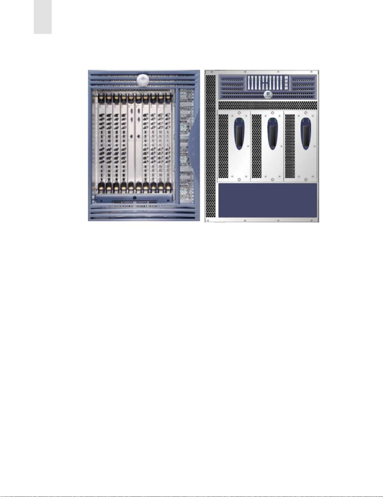
unprecedented performance, scalability, flexibility, functionality, reliability and availability. Figure1-1
shows two views of the SilkWorm 12000. Several key features of the SilkWorm 12000 and the Fabric
operating system (Fabric OS) are detailed below:
1
• The dual switch capability allows either one or two 64-port switches per chassis. The switches may
be interconnected together to create a single high port count fabric, or they may be used in a highly
available redundant fabric SAN. Dual redundant control processors (CP) provide high availability
within the chassis. The control processors are located on the CP cards.
• The SilkWorm 12000 is based on Brocade’s third generation technology, which supports 1 and 2
Gbit/sec auto-sensing Fibre Channel ports. Trunking technology groups up to four ports together to
create high performance 8 Gbit/sec ISL trunks between switches.
• Universal ports self-configure as E-ports, F-ports, or FL-ports.
• Small Form-Factor Pluggable (SFP) optical transceivers support any combination of Short
Wavelength (SWL) and Long Wavelength (LWL) optical media on a single switch module
(hereafter called 16-port card).
• Fully networkable, the SilkWorm 12000 offers forward and backward compatibility with all
Brocade SilkWorm switches.
• High availability, redundant design, extensive diagnostics, and system monitoring capabilities
integrated with Fabric OS management tools deliver unprecedented Reliability, Availability, and
Serviceability (RAS).
• The SilkWorm 12000 offers a highly available platform for mission-critical SAN-designed
applications.
• Extensible and multi-protocol to support 1 Gbit/sec, 2 Gbit/sec and 10 Gbit/sec Fibre Channel, IP,
and InfiniBand protocols.
Publication Number 53-0000251-02 1-1
Page 12
1
Introducing the SilkWorm 12000
Cable Side (Front)
Figure 1-1 Cable and non-cable side views of the SilkWorm 12000
Non-Cable Side (Rear)
Hardware
The SilkWorm 12000 features a modular and scalable mechanical construction that allows a wide range
of flexibility in switch installation, Fabric design, and maintenance. Using a 14U (rack unit) mechanical
design, up to three SilkWorm 12000 chassis may be mounted in a standard 42U rack, supporting as many
as 384 Fibre Channel ports in a single rack. As shown in Figure 1-2, the modular multi-card assembly
chassis of the SilkWorm 12000 consists of the following:
• Up to eight hot-swappable 16-port cards, delivering up to two separate 64-port Fibre Channel
switches in a single chassis. Each 64-port switch uses four 16-port cards.
• Two slots for Control Processor cards.
- A single active CP card can control both 64-port switches in the chassis.
- A redundant CP card can assume control of a single or dual switch configuration in the event of
an active CP failure.
• Modular hot-swappable Field Replaceable Units (FRUs):
- 16-Port Card
- Control Processor Card (CP Card)
- Small Form-Factor Pluggable (SFP) optical transceivers
- Blower assembly
- Power supply
Figure 1-2 identifies the components as described above.
1-2 Publication Number 53-0000251-02
Page 13
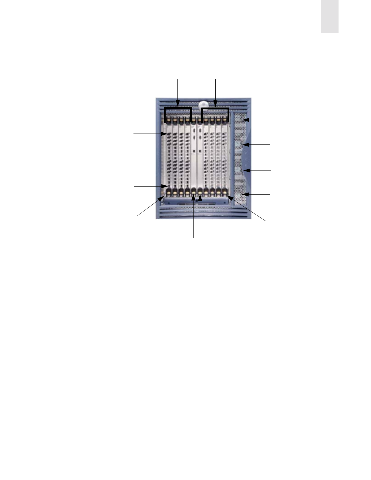
Port 15
16-port cards
Slot numbers
1-4
Introducing the SilkWorm 12000
7-10
Power supply #4
Power supply #3
Power supply #2
1
Port 0
Slot 1
Figure 1-2 SilkWorm 12000 With Identified Components
High Availability
High availability is an all-encompassing term, and this term normally includes attributes such as
reliability and availability. If a system is under continuous operation, it is accessible 7 days a week and
24 hours per day by users and the system manager. Availability is designated in terms of 9s. For example,
the architecture of the SilkWorm 12000 is designed for availability in excess of 99.999%.
The following features contribute to the high availability design of the SilkWorm 12000:
• Redundant, hot-swappable components
• Redundant power and cooling subsystems
• No single point of failure
• Enhanced data integrity on all data paths
• Fabric Shortest Path First (FSPF) automatic rerouting around failed links
• Integration with SNMP managers
• Automatic Contro l Pr ocessor fail over
Power supply #1
Slot 10
2 CP cards
Slot numbers 5 and 6
Publication Number 53-0000251-02 1-3
Page 14

1
Introducing the SilkWorm 12000
The SilkWorm 12000 high availability software architecture provides a common framework for all
applications that reside on the system and allows global and local states to be maintained such that any
component failure is fully manageable. High availability elements consist of the High Availability
Manager, the heartbeat, the fault/health framework, the replicated database, initialization, and software
upgrade. The software high availability model is discussed in more detail later in this section.
The power supplies (four total) support two 64-port switches in a chassis with the ability to tolerate the
failure of as many as two power supplies. The power supplies are hot-swappable, without taking the
switch down and without incurring any outage.
The blower assemblies (three total) are also hot-swappable and the chassis can operate fully with only
two blower assemblies in place allowing for the failed blower assembly to be replaced with no outage.
The recommended systems networks for high availability include the use of redundant fabrics and dual
paths from hosts to storage devices in a SAN. When dual fabrics are used, one switch, one link, or an
entire fabric can go down, but data traffic will be re-routed to the alternate path ensuring that the SAN
remains operational.
Reliability
In addition to being available, the system must be reliable. This means that some, if not all, of its internal
state must be maintained. In a reliable system, a user is not aware of the internal state of the chassis
components and will experience continued system service with zero degradation of service.
The SilkWorm 12000 provides the following features to ensure reliability. All data inside the switch is
protected by the following Error Detection and Correction mechanisms as follows:
• Power-on self test (POST)
• Error detection and fault isolati on (EDFI), such as cyclic redundancy checking (CRC), parity
checking, checksum, and illegal address checking
• Dual control processors, with each control processor containing two serial ports and one Ethernet
port. Offline Control Processor diagnostics and remote diagnostics make troubleshooting
straightforward.
2
• I
C monitoring and control of environmental conditions
Fault Monitoring and Diagnostics
Fault monitoring, diagnostic tests, and system status indicators simplify management and ensure
availability of the SilkWorm 12000.
Diagnostic testing occurs in three areas: Power-On Self Test (POST), switch level testing, and
manufacturing tests. The Power-On Self T est is card oriented and ensures that the switch is ready for use
during power up. Switch level testing is done at the user port level. These tests rely on th e standard
Fabric OS support to provide routing and port setup. Manufacturing support includes long duration
testing.
The WWN card located on the non-cable side of the switch summarizes the system status of each 16-port
card, each Control Processor Card, and each power supply module. LEDs on the blowers show the status
of the blower assemblies.
1-4 Publication Number 53-0000251-02
Page 15

Introducing the SilkWorm 12000
Brocade’s Fabric Watch exposes enhanced status reporting capabilities of the SilkWorm switches
through all the standard management interfaces, including SNMP, the Fabric Access Layer API, Brocade
Web Tools, Fabric Manager, and the command line interface.
Intelligent Fabric Services Architecture
Fabric OS v4.0 (required for the Silk Worm 12000) provides a wide variety of Advanced Fabric Services
that are designed to improve the investment protection, security, performance, scalability, and efficiency
of Brocade SAN fabrics.
Features of Fabric OS v4.0 include Trunking, Advanced Zoning, and Advanced Performance
Monitoring. These features, some of which are also available in previous versions of Fabric OS, are
discussed in the following pages.
Advanced Performance Monitoring
Advanced Performance Monitoring (available on 2 Gbit/sec switches) can monitor performance
characteristics on any attribute within the first 64 bytes of a Fibre Channel frame. Predefined graphs
measure end-to-end performance; port, switch, and AL-PA bandwidth utilization; SCSI commands
(read, write, and read/write); and protocol comparisons (SCSI versus IP). As a result, performance
monitoring provides the foundation for performance tuning, resource optimization, service level
agreement compliance reporting, and bill-back applications.
1
Advanced Zoning
Advanced Zoning software limits access to data by segmenting a fabric into virtual private SANs. On
1 Gbit/sec and 2 Gbit/sec switches, software-enforced zoning prevents hosts from discovering
unauthorized target devices. Hardware-enforced zoning prevents a host from accessing a device that is
unauthorized. This provides the most secure zoning available. In addition, Advanced Zoning on
2 Gbit/sec switches enables hardware enforcement for devices identified by W orld Wide Name (WWN).
This is new functionality that was not available in the SilkWorm 2000 series switches, which could only
do soft WWN zoning. With WWN zoning, zone enforcement adjusts automatically, even if a device
moves to another port. This new zoning model allows for the continued flexibility that traditional
software-enhanced zoning provides plus garners the security benefits of legacy hardware-enforced
zoning.
Extended Fabrics
Extended Fabrics software enables long distance (100km) ISLs over dark fiber or Dense Wave Division
Multiplexing (DWDM) connections at full bandwidth.
Publication Number 53-0000251-02 1-5
Page 16

1
Introducing the SilkWorm 12000
Fabric Watch
Fabric Watch software enables organizations to set thresholds and ranges for SAN fabrics, and raise
management alerts when performance or errors vary outside predefined ranges.
ISL Trunking
ISL Trunking increases the performance and availability of links between 2 Gbit/sec switches and
minimizes the SAN management effort. Up to four 2 Gbit/sec ISLs between two switches can be
combined into a single trunk, or logical ISL, at 8 Gbit/sec. Traffic is load balanced across all the links
(i.e. any traffic can go across any available trunk link). This is an improvement over current static routing
and load sharing where servers are allocated individual dedicated links.
QuickLoop/Fabric Assist (QLFA)
QuickLoop/Fabric Assist (QLF A) connects private loop hosts to the SAN fabric for better performance
and fault management, while protecting investments in legacy loop devices. Because many legacy
devices are designed for FC-AL configurations, Fabric OS translative mode protects investments by
supporting private loop target devices. The SilkW orm 12000 running Fabric OS v4.0 supports translative
mode. Therefore switches that do support QuickLoop or Fabric Assist can be connected to a SilkWorm
12000, even though the SilkWorm 12000 does not support QuickLoop or Fabric Assist directly. It is
possible to connect devices that are accessed by QuickLoop/Fabric Assist devices to the SilkWo rm
12000. This means that any type of target device may be attached to a switch running Fabric OS v4.0 and
may be included in a QuickLoop Fabric Assist zone that has its private host attached to a switch running
QuickLoop and Zoning. QuickLoop and Zoning are pre-requisites for QLFA, on Fabric OS v2.3 or later
(SilkWorm 2xxx) or v3.0.1 or later (SilkWorm 3800/3200).
1-6 Publication Number 53-0000251-02
Page 17

SilkWorm 12000 Architecture and What Is New
This chapter includes the following sections:
• Fabric OS 4.0 on page 2-1
• Dual Switch Model on page 2-2
• Port Addressing and Area Numbering on page 2-5
• Compatibility on page 2-10
• Software High Availabil ity Model on page 2-11
Note: All topics in this section establish a foundation for further discussions regarding the design,
operation, and management of the SilkWorm 12000 and SilkWorm 12000 based SANs. Where
appropriate, detail is provided in this section to identify key changes between the SilkWorm
12000 and previous SilkWorm switch models or to highlight key architectural features.
2
The SilkWorm 12000 utilizes embedded Linux as its underlying operating system, however all SAN
management is still performed on the Fabric OS level. While the impact to previous users of SilkWorm
switches is nominal, it is important to note what has changed, and what prompted these changes. The
dual switch model introduces several new concepts that are important to understand for the design,
deployment, and maintenance of the SilkWorm 12000 and SilkWorm 12000-based SANs. The 16-port
card design of the SilkWorm 12000 introduces a new “slot” operand to many commands, and a new
model for port identification that should be understood for effective operation of the SilkWorm 12000.
The SilkWorm 12000 is compatible with all Brocade switch models and is interoperable with switches
from vendors such as McData. To enable this compatibility, you must change certain configuration
settings before connecting other switches to the SilkWorm 12000. Finally , the software high availability
architecture is discussed.
Fabric OS 4.0
Fabric OS v4.0 is built upon a real-time version of Linux version 2.4. Linux was chosen due to industry
wide support for hardware and software, portability, and scalability. Figure 2-1 shows the screen output
when booting the switch. Notice the references to Linux.
Publication Number 53-0000251-02 2-1
Page 18

2
SilkWorm 12000 Architecture and What Is New
The system is coming up, please wait...
Checking system RAM - press any key to stop test
Checking memory address: 08000000
System RAM check complete
Press escape within 4 seconds to enter boot interface.
Entry point at 0x00400000 ...
Loading Initial RAM disk
Uncompressing Linux... done.
read_silkworm_bdinfo: silkworm->board = 10, silkworm->board_rev =2
id mach(): done
Physical Memory: 0x08000000 Used memory = 0x07f00000
Linux version 2.4.2-mvista_010329 (swrel@nermal) (gcc version 2.95.3 20010112
(prerelease)) #1 Tue Dec 11 00:39:11 PST 2001
Figure 2-1 SilkWorm 12000 Boot Up With Fabric OS v4.0
Fabric OS 4.0 is a superset of previous versions of Fabric OS, so most commands used with previous
versions as well as several new commands are available.
Warning: The SilkWorm 12000 is equipped with a Root account intended for diagnostics and
debugging purposes solely by the trained engineers of the equipment vendor. Improper use of the
functionality made available through the Root account, such as treating the SilkWorm 12000 like
a standard Linux system and using the Linux functions and commands, can cause significant
harm and disruption to the operation of the SAN fabric. During normal operation, log in to the
switch as the “admin” user. The “admin” user utilizes a res tricted shell with access to Fabric OS
commands only.
Dual Switch Model
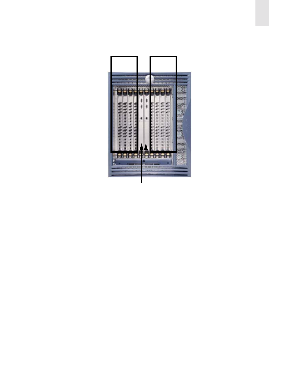
The SilkWorm 12000 houses two separate logical switches within a single chassis. Each switch is
capable of scaling to 64 ports by adding up to four 16-port cards to the respective logical switch. It is
possible to interconnect the two switches inside a chassis to form a fabric. Each logical switch has its
own unique domain ID, WWN, and IP address. Each switch in the chassis is an entity accessible through
telnet and other methods, using the unique IP address of that switch. The switches are numbered zero and
one, as shown in Figure 2-2. You can also access a switch using a serial connection for installation, such
as for setting the IP address of the switch or for diagnostic purposes.
2-2 Publication Number 53-0000251-02
Page 19
SilkWorm 12000 Architecture and What Is New
2
Logical
Switch 0
Logical
Switch 1
cp0 cp1
Figure 2-2 SilkWorm 12000 Dual-Switch Model
Dual Control Processors For High Availability
The dual control processors (CP) operate in an active/standby model. The CP cards are named “cp0” (the
CP card on the left, when looking at the chassis) and “cp1” (the CP card on the right when looking at the
chassis), as shown in Figure 2-2. Each CP card is assigned an IP address for maintenance and diagnostic
purposes. Cp0 is located in slot 5 and cp1 is located in slot 6. One CP card is active and manages both
switches. The other CP card is in standby mode and will become active when a failover is required or a
forced failover occurs. Both CP cards should run the same version of Fabric OS. When configured for a
single switch, meaning only one switch is populated with 16-port cards, it is still necessary to have two
CP cards to maintain availability should one CP card fail. Normally, cp0 is given preference to become
the active CP card and cp1 operates as the standby CP card. In the initial release of Fabric OS v4.0, when
a failover occurs, it takes approximately thirty seconds before the standby CP card becomes active. The
use of a dual fabric solution can mitigate or eliminate the impact of this failover period. During the
failover period, I/O is not possible and attached devices must log back into the fabric and re-authenticate.
In properly designed high availability SANs, the real effect on I/O can be limited to as little as four
seconds. The next release of Fabric OS v4.1 is planned to support completely non-disruptive updates to
minimize path interruption.
Publication Number 53-0000251-02 2-3
Page 20

2
SilkWorm 12000 Architecture and What Is New
The dual CP card model and the concept of logical switches is a change from past SilkWorm switch
implementations. The SilkWorm 2000 and 3000 families of 8-port and 16-port switches all had a static
relationship between the processor and the switch. Now the switch and the processor are de-coupled.
One implication of this model is that instead of downloading firmware to a switch, it is necessary to
download firmware to a CP card.
Note: The time it takes to activate the standby CP, when a failover occurs, will be considerably less
when using Fabric OS 4.1 and greater.
Accessing the SilkWorm 12000 Switches
When accessing SilkWorm 12000 switches, it is possible to access either switch by its respective IP
address or by using a serial connection to the active CP card. It is possible to access a CP card by telnet
using the respective CP card’s IP address or by connecting a serial cable to the CP card. Access to the CP
card should be limited to: installation purposes, setting a switch’s IP address, doing firmware
maintenance (i.e., downloads), or for diagnostic purposes.
When telnetting to an inactive CP card, the user is entered into a limited access environment where no
access to a switch is possible. When a user accesses an active CP card, that user will have access to the
full Fabric OS environment. To determine a CP card state, whether inactive or active, use the command
haShow (see Figure 2-3). When telnetting to a SilkWorm 12000 switch, the user will encounter a login
prompt from the active CP card. This may seem confusing, since the destination is a switch and not the
CP card; however, once logged in, the user is then placed into the tar get switch environment, as shown in
Figure 2-4.
Note: While it is possible to access the switches via the active CP card, either using an Ethernet address
or serial connection, primary access to the switches should be via Ethernet to the switch and not
the CP card.
sun1# telnet sw0_156_22
Trying 192.168.156.22...
Connected to sw0_156_22.
Escape character is '^]'.
Fabric OS (cp1)
cp1 login: admin
Password:
sw0_156_22:admin> hashow
Local CP (Slot 6, CP1): Active
Remote CP (Slot 5, CP0): Standby
HA Enabled, Heartbeat Up
Figure 2-3 Determining a CP Card State Using the haShow Command. CP1 is Active.
sun1# telnet sw1_156_23
Trying 192.168.156.23...
Connected to sw1_156_23.
Escape character is '^]'.
Fabric OS (cp1)
cp1 login: admin
Password:
sw1_156_23:admin>
Figure 2-4 SilkWorm 12000 Log In
2-4 Publication Number 53-0000251-02
Page 21

SilkWorm 12000 Architecture and What Is New
2
How Logical Switch Behavior Differs
The behavior of several commands have changed in Fabric OS v4.0 to account for the dual CP card
architecture. For example, the command reboot now will reboot the active CP card and both logical
switches if issued from a switch. This happens since the logical switches run on the active CP card and
the reboot command will cause the active CP card to reboot and a failover to the standby CP card will
occur. There is a new command in Fabric OS v4.0 that should be used to reboot a switch. This command
is called switchReboot and this command will only affect that switch from which the command is issued.
Note: Use the command switchReboot to reboot a switch. Use of the reboot command from a logical
switch will result in the reboot of the active CP card, causing both logical switches to failover to
the standby CP card.
Also, users and their passwords are now associated with a chassis. This means that the user/password
pairs are the same for both logical switches and the CP cards. If the password for user admin is changed
on switch 0, the password will also be changed for switch 1 and the CP cards.
Note: Some commands, such as passwd, are chassis-wide in scope and affect both logical switches.
Port Addressing and Area Numbering
Port addressing is different for the SilkWorm 12000 than with the SilkWorm 2000 and 3000 families of
8-port and 16-port switches. The change in port addressing is driven by several factors, including the
high port density of the SilkWorm 12000, the need to eliminate ambiguity, to enable consistent marking
of port numbers on the 16-port card, and to accommodate future cards that may implement varyi ng port
densities. The physical ports on the 16-port cards are numbered zero through fifteen from bottom to top
and up to four 16-port cards can comprise a logical switch. It is necessary to relate a physical port
number to a card to uniquely identify that port. Port oriented commands, such as portShow, now require
that the slot be specified so that a port can be uniquely identified. The syntax is command slot/
port, as follows in Figure 2-5.
Publication Number 53-0000251-02 2-5
Page 22

2
SilkWorm 12000 Architecture and What Is New
sw0_156_22:admin> portShow 1/7
portCFlags: 0x0
portFlags: 0x20801 PRESENT DISABLED LED
portType: 1.1
portState: 2 Offline
portPhys: 5 No_Sync
portScn: 2 Offline
portId: 160700
portWwn: 20:07:00:60:69:80:04:a0
Distance: normal
portSpeed: 2Gbps
Interrupts: 107 Link_failure: 1 Frjt: 0
Unknown: 13 Loss_of_sync: 10 Fbsy: 0
Lli: 31 Loss_of_sig: 0
Proc_rqrd: 72 Protocol_err: 0
Timed_out: 0 Invalid_word: 0
Rx_flushed: 0 Invalid_crc: 0
Tx_unavail: 0 Delim_err: 0
Free_buffer: 0 Address_err: 8
Overrun: 0 Lr_in: 0
Suspended: 0 Lr_out: 0
Parity_err: 0 Ols_in: 0
2_parity_err: 0 Ols_out: 0
CMI_bus_err: 0
Figure 2-5 Port Related Commands Require Input Of Slot Number/Port Number
Indirectly affected by the new port-addressing scheme are commands that reference a port ID, which is
the 24-bit fabric address, assigned by the switch. Some examples of commands that are indirectly
affected by the change in port ID are nsShow, nsAllShow, and portLogDump. Knowing the port ID of a
device enables the decoding of the physical location of a particular device. The previous method for
decoding a port ID for the 8-port and 16-port SilkWorm 2000 and 3000 family switches is shown in
Figure 2-6.
This is the Port Addressing Format:
0 x XX 1Y ZZ
where:
• XX is a value between 0x1 to 0xef inclusive and indicates the doma in ID of the switch to
which the device is attached
• The “1” will always be there in 2000 series & 3800 switches
• Y is the port number (0-F hex) that the device is attached
• ZZ is the AL_PA for a FL_Port or 00 for an F_Port
Example: 021500
where:
XX=02 Domain_ID of the switch
Y=5 Port #
ZZ=00 an F_Port
Figure 2-6 Decoding Port ID For Fabric OS v2.x and 3.x
2-6 Publication Number 53-0000251-02
Page 23

SilkWorm 12000 Architecture and What Is New
The port-addressing scheme for Fabric OS v4.0 is summarized in Figure 2-7.
This is the Port Addressing Format:
0 x WW XY ZZ
where:
• WW is a value between 0x1 to 0xef inclusive and indicat es the dom a in id of the sw itch to
which the device is attached
• X is the logical port card number
• Y is the port number (0-F hex) that the device is attached
• ZZ is the AL_PA for a FL_Port (Loop) or 00 for an F_Port
Example 1: 170f00
where:
WW =23 Domain_ID of the switch
X= logical port card 0
Y= port number 15 (0xf)
ZZ=00 an F_Port.
2
Example 2: 162ed2
where:
WW =22 Domain_ID of the switch
X= logical port card 2
Y= port number 14 (0xe)
ZZ=d2 ALPA (FL_Port)
Figure 2-7 Decoding Port ID For Fabric OS v4.0
Since the port-addressing scheme has changed for the SilkWorm 12000, so has the decoding for a
particular port ID. The concept of area number is new in the SilkWorm 12000. The area number is used
in the same way a port number is used for the SilkWorm 2000 series and 3800 switches. When
specifying zoning configurations by port number it is necessary to utilize the area number. Also several
commands, such as switchShow or nsShow, specify area number in the output (see Figure 2-8).
Publication Number 53-0000251-02 2-7
Page 24

2
SilkWorm 12000 Architecture and What Is New
sw1_156_23:admin> switchshow
switchName: sw1_156_23
switchType: 10.1
switchState: Online
switchRole: Subordinate
switchDomain: 23
switchId: fffc17
switchWwn: 10:00:00:60:69:80:04:a1
switchBeacon: OFF
blade7: Beacon: OFF
blade8: Beacon: OFF
Area Slot Port Gbic Speed State
=====================================
0 7 0 id N2 Online E-Port 10:00:00:60:69:50:09:2b "sw1"
(upstream)
1 7 1 id N2 Online E-Port 10:00:00:60:69:50:09:2b "sw1"
2 7 2 -- 2G No_Module
3 7 3 id 2G No_Light
4 7 4 id 2G No_Sync Disabled
5 7 5 -- 2G No_Module
6 7 6 -- 2G No_Module
7 7 7 -- 2G No_Module
8 7 8 -- 2G No_Module
9 7 9 -- 2G No_Module
10 7 10 -- 2G No_Module
11 7 11 -- 2G No_Module
12 7 12 -- 2G No_Module
13 7 13 -- 2G No_Module
14 7 14 -- 2G No_Module
15 7 15 -- 2G No_Module
16 8 0 id N2 Online F-Port 10:00:00:00:c9:27:2c:fe
17 8 1 id N2 Online F-Port 10:00:00:00:c9:28:c8:43
18 8 2 id N1 Online F-Port 20:00:00:60:16:3c:9f:16
19 8 3 id N1 Online F-Port 20:00:00:60:16:3c:9e:e8
20 8 4 -- 2G No_Module
21 8 5 -- 2G No_Module
a. Output trunctuated to fit in diagram
a
Figure 2-8 SwitchShow Command Output Specifies Area Number
Each logical switch consists of four slots and up to four 16-port cards. Both logical switches consist of
logical switch port cards 0 through 3 (see Table 2-2).
To calculate the area number of a port in the SilkWorm 12000, multiply the switch logical port card
number by sixteen, add the port number, and convert the value to hexadecimal. SeeTable 2-1 for a
complete map of physical ports to addresses.
Example:
12000 area number = logical port card number * 16 + port number
convert the value obtained above to hexadecimal
The calculation of a physical switch slot is obtained by adding one to the logical port card number for
switch 0 and seven to the logical port card number for switch 1.
Example:
switch 0 physical slot number = logical port card number + 1
switch 1 physical slot number = logical port card number + 7
2-8 Publication Number 53-0000251-02
Page 25

SilkWorm 12000 Architecture and What Is New
In addition to the calculation method, you can determine the area by looking it up in Table 2-1.
Table 2-1 Logical Port Card Numbers
Port 0 1 2 3
15 0F 1F 2F 3F
14 0E 1E 2E 3E
13 0D 1D 2D 3D
12 0C 1C 2C 3C
11 0B 1B 2B 3B
10 0A 1A 2A 3A
909192939
808182838
707172737
606162636
505152535
2
404142434
303132333
202122232
101112131
000102030
Note: If you look at the left-most digit in the Area, that corresponds to the logical port card. The rightmost digit corresponds to the port.
One method to derive the logical switch number (either 0 or 1) is to use the “myid” command:
Example 1:
switch0:root> myid
Current Switch: switch0
Session Detail: Console Port (/dev/ttyS0) Active Redundant
Example 2:
switch0:root> myid
Current Switch: switch0
Session Detail: Console Port (/dev/ttyS0) Standby Redundant
Example 3:
switch1:root> myid
Current Switch: switch0
Session Detail: switch1 (192.168.148.30) Active Redundant
Example 4:
switch0:root> myid
Current Switch: switch1
Session Detail: cp1 (192.168.148.32) Active Non-Redundant
Publication Number 53-0000251-02 2-9
Page 26

2
SilkWorm 12000 Architecture and What Is New
Additionally, if meaningful switch names are used, you can simply look at the telnet prompt. In the
above example, the switch name is “sw0” which intuitively tells you that you are on switch 0.
All of the above mentioned relationships are summarized in Table 2-2.
Table 2-2 Logical Switch Numbers
Physical Slot Logical Port
Logical Switch 0 1 0
21
32
43
Logical Switch 1 7 0
81
92
10 3
Card
Compatibility
The SilkWorm 12000 is compatible with all previous versions of SilkWorm switches including the
SilkW orm 2000 and 3000 families of switches. The SilkW orm 12000 is interoperable with switches from
other vendors, such as McData. To enable compatibility with 8-port and 16-port SilkWorm 3000 series
switches, it is necessary to run Fabric OS 3.0.2c or later on these switches, and Fabric OS v2.6 or later
for SilkWorm 2000 series switches.
When connecting a switch from the SilkWorm 2000 and 3000 product family to a SilkWorm 12000, you
must enable the Core Switch PID Format parameter. You can do this using the configure command as
shown in Figure 2-9. If you do not enable the Core Switch PID Format parameter (by setting the value to
1), the fabric will segment when connecting these switches to a SilkWorm 12000.
Note: When deploying the SilkWorm 12000 into existing fabrics that also include SilkW orm 2000 and
3000 series switches, it is necessary to change the Core Switch PID format setting on those
switches. Doing so may have an impact on existing applications, as enabling this setting changes
the 24-bit address. A dual fabric architecture can mitigate or eliminate downtime if it is
necessary to change the core PID format.
2-10 Publication Number 53-0000251-02
Page 27

SilkWorm 12000 Architecture and What Is New
sw3:admin> switchDisable
sw3:admin> configure
Configure...
Fabric parameters (yes, y, no, n): [no] y
Domain: (1..239) [3]
BB credit: (1..27) [16]
R_A_TOV: (4000..120000) [10000]
E_D_TOV: (1000..5000) [2000]
Data field size: (256..2112) [2112]
Sequence Level Switching: (0..1) [0]
Disable Device Probing: (0..1) [0]
Suppress Class F Traffic: (0..1) [0]
SYNC IO mode: (0..1) [0]
VC Encoded Address Mode: (0..1) [0]
Core Switch PID Format: (0..1) [0] 1
Per-frame Route Priority: (0..1) [0] ^D
Committing configuration...done.
sw3:admin> switchEnable
2
Figure 2-9 Enabling Compatibility Between the SilkWorm 12000 and other SilkWorm
Switches
To enable compatibility between a SilkWorm 12000 switch and another vendor’s switch, it is necessary
to invoke interoperability mode. Operating the Brocade switch in this mode places significant
restrictions on the Brocade SilkWorm 12000 switch. Functionality such as Hard Zoning, Extended
Fabrics, and Virtual Channels will not be available. Refer to the Fabric OS Procedures Guide for
information on procedures and restrictions when implementing interoperability mode.
Software High Availability Model
The high availability software architecture of the SilkWorm 12000 provides a common framework for all
applications that reside on it, enabling global and local states to be maintained such that any component
failure is fully manageable. High availability elements consist of the High Availability Manager, the
heartbeat, the fault/health framework, the replicated database, initialization, and software upgrade.
The High Availability Manager (HAM) uses an Active-Standby model. HAM controls access to the
standby CP card, facilitates software upgrades, prevents extraneous switchover activity, closes and
flushes streams as needed, provides flow control and message buffering, and supports a centralized
active and standby state allowing the Switch of Activity (SWACT) to be controlled from a single point.
Failover Overview
The two methods used to notify each CP card of the health of the other are a network based heartbeats
and hardware handshaking control lines. HAM manages the IP address used to access each logical
switch and the standby CP card. Figure 2-10 is a block diagram of the failover process. In the case of
Figure 2-10, the command haFailover is used to cause a failover. CP0 is the HA master (that is, the
active CP card) and all the switch applications running on it are controlling the fabrics for switch 0 and
switch 1. CP1 is in standby mode and the applications are in wait for active mode. The administrator
Publication Number 53-0000251-02 2-11
Page 28
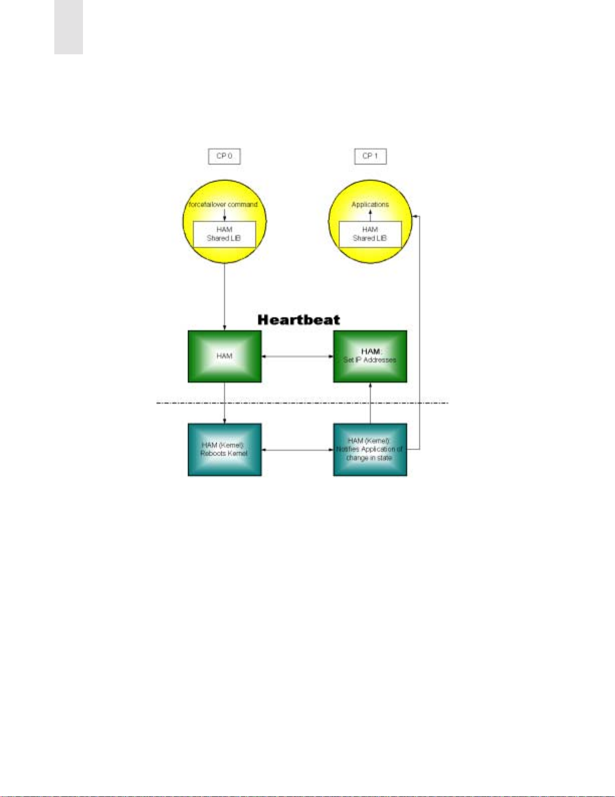
2
SilkWorm 12000 Architecture and What Is New
issues the haFailover command and the HAM demon on CP0 reboots the kernel. The HAM demon on
CP1 is notified of the loss of CP0 through the hardware control lines, changes it’s state from standby to
master, configures the switch IP addresses for it’s LAN interface and notifies the switching applications
that they are now running as active on CP1.
Figure 2-10 Block Diagram of the High Availability Fail Over Process
Failover Details
The failover process is essentially invisible to the switch administrator. Whether the active CP card is
CP0 or CP1 really has no bearing on the operation of the switches. All switch information, such as the
switch configuration, zoning, SNMP settings, Fabric Watch settings, etc. is preserved and independent of
the CP card. When a CP card failure occurs, there is some impact to the switches and the associated
fabrics. In the initial release of Fabric OS v4.0, when a failover occurs, it takes approximately twenty
seconds before the standby CP card becomes active. The use of a dual fabric solution can mitigate or
eliminate the impact of this failover period. During the failover period, I/O is not possible and attached
devices must log back into the fabric and re-authenticate. The next release of Fabric OS 4.x is planned to
support completely non-disruptive updates to minimize path interruption. For smaller fabrics, consisting
of a few switches, the fabric becomes operational (meaning I/O can resume) once the CP becomes
2-12 Publication Number 53-0000251-02
Page 29

SilkWorm 12000 Architecture and What Is New
active. For larger fabrics, it may take longer for the fabric to become operational since the higher number
of switches in the fabric necessitates a longer convergence period before the fabric becomes operational.
At the time a failover occurs, all devices and ISLs connected to switch 0 and switch 1 lose their link until
the failover completes. Also any active telnet sessions to the switches or the CP cards are disconnected.
Note: The time it takes to activate the standby CP, when a failover occurs, will be considerably less
when using Fabric OS 4.1 and greater.
2
Publication Number 53-0000251-02 2-13
Page 30

2
SilkWorm 12000 Architecture and What Is New
2-14 Publication Number 53-0000251-02
Page 31

SilkWorm 12000 Based SAN Designs
This chapter includes the following sections:
• Scalability on page 3-3
• Performance on page 3-4
• Availability on page 3-8
• SilkWorm 12000 Ba sed Fabric Topologies on page 3-10
This chapter assumes that the reader is familiar with the following concepts:
• Core/edge topology characteristics
• Locality
• Multi-fabric architectures
• Congestion
• Over-subscription
• Device placement strategies
3
For detailed information about the concepts listed above, refer to the Brocade SAN Design Guide (part
number: 53-0000231) and the book Building SANs with Brocade Fabric Switches by Syngress press
(ISBN: 1-928994-30-x).
The SilkWorm 12000 is an exceptionally flexible storage-networking switch. Its enhanced network
features, high port density, high availability, and broad compatibility allow this switch to fill many
different roles. It can be used to form a single-switch 64-port fabric, a two-switch fabric of up to 124
ports, a member of a full mesh, or the core or edge of a highly scalable core/edge fabric. The SilkWorm
12000 is also backwards compatible with the SilkWorm 2000 and 3000 series switches to protect
customer investment. Figure 3-1 illustrates these topologies.
Publication Number 53-0000251-02 3-1
Page 32

3
SilkWorm 12000 Based SAN Designs
1-41-4
4 x 12000
up to 248 Available
Fabric Ports
Figure 3-1 The SilkWorm 12000 Excels In Many Fabric Topologies
While Brocade switches have the flexibility to support many topologies, the core/edge topology is the
best “general purpose” choice. The core/edge topology delivers high performance, availability, and
scalability. It is widely deployed in the SAN marketplace, and extensively tested by Brocade and other
companies.
1 x 12000
64 Available Fabric Ports
2 x 12000
up to 124 Available Fabric Ports
4 x 12000 , 24 x 16-port switches
up to 500 Available Fabric Ports
1-4
1-4
1-4
1-41-41-4
Limited high-level discussions of general SAN design concepts and other topologies are included in this
document, however the primary focus is the core/edge topology and how to effectively design core/edge
SANs using the SilkWorm 12000.
3-2 Publication Number 53-0000251-02
Page 33

Scalability
A key question in the initial design stage of any SAN is the need for scalability. With fabrics built from
16-port switches, the core/edge topology is the dominant choice. It is possible to scale a core/edge fabric
from 16 ports to 224 ports using the same architecture without downtime. While other topologies are
possible, the scaling of these topologies is limited and disruptive wit h 16-port switches.
With the SilkWorm 12000, topologies such as the full and partial meshes are more practical since it is
possible to scale these topologies beyond 200 ports. This is because the SilkWorm 12000 has a much
higher port density. Additionally, trunking capabilities optimize the performance between switches,
making the full and partial mesh topologies more efficient.
If the network will expand to beyond a few hundred ports, the core/edge is the topology of choice. Even
with the SilkWorm 12000, topologies such as the full mesh are difficult to scale past a few hundred ports
non-disruptively or without significant re-cabling. If you use a large port-count switch at the core of your
fabric, you greatly increase that fabric’s scalability.
Scaling requirements can also dictate device placement strategies. For example, an initial deployment of
a core/edge fabric may leave ports free on the core switches. Placing nodes on these ports can allow full
utilization of the fabric. However, each core port can only be used as a node connection point or an ISL
connection point. When an ISL connection point is utilized for a SAN device, potentially dozens of
nodes of scalability are given up. A very large fabric that needs to scale past several hundred ports should
not have nodes directly connected to the core as these devices would have to be later moved to facilitate
growth. If the scaling requirements are below a few hundred ports or it is accpetable to re-cable devices,
then attaching devices to the core is aviable option.
SilkWorm 12000 Based SAN Designs
3
The cores of a pre-existing core/edge fabric built with 16-port switches can easily be upgraded to
SilkWorm 12000 cores. This allows investment protection and scalability without dow ntime. The
preservation of the investment in existing switches is a hallmark of Brocade’s backward compatibility
strategy.
In addition to investment protection, per-port cost economics plays a role in the SAN design process. It is
now possible to build multi-hundred port SANs using only 16-port switches, only 64-port switches, or a
mixture of both. Each approach has benefits: some may prefer a distributed network approach that
leverages lower cost 16-port switches, as others may prefer smaller networks of higher port count
switches with fewer ISLs. Fiber budgets in campus environments may also impact this decision. As the
16-port switches can be deployed through a data center or campus they may require fewer longer runs
between devices and larger central switches. A combination of the smaller and larger port count switches
may offer a good design solution.
Note: When considering campus or large data center environments, a combination of smaller and larger
port count switches may offer a more practical solution. Since fewer runs between devices and
central switches are possible by locating satellite switches with the devices.
The SAN designer has the ability to mix and match switches, leverage backwards compatibility, and
preserve investment when creating a SAN design. This allows the SAN to be tailored to the cost and
management requirements of the customer.
Publication Number 53-0000251-02 3-3
Page 34

3
SilkWorm 12000 Based SAN Designs
Performance
The SilkWorm 12000 delivers many enhanced performance capabilities over previous generation
switches. It is possible to dynamically tune a fabric by adding or removing ISLs between SilkWorm
switches. With Trunking (SilkWorm 12000, 3800, and 3200), th is tuni ng ability is further enhanced
because trunking makes ISL addition transparent to SAN devices and optimizes ISL bandwidth
utilization. Current SAN devices are predominantly limited to 1 Gbit/sec, with a rapid migration to
2 Gbit/sec in progress. Today’s 1 Gbit/sec devices are rarely able to sustain a 1 Gbit/sec I/O stream. This
enables Brocade 1-2 Gbit/sec auto sensing switches to aggregate many 1 Gbit/sec streams across fewer
2 Gbit/sec ISLs. ISL over-subscription is much like the fan-in and fan-out principals used by RAID array
vendors: it decreases cost without affecting real-world performance. Trunking, dynamic tuning
capabilities, and 1 Gbit/sec to 2 Gbit/sec aggregation combine to create a flexible, powerful, and high
performance fabric infrastructure.
ISL Over Subscription
When designing a SAN, it is important to understand performance boundaries of nodes such as storage
fan-out ratios and HBA performance limits. While any SAN device that connects to a SAN at 2 Gbit/sec
is theoretically capable of 2 Gbit/sec. In reality, that device is most likely to sustain a much lower I/O
throughput. If a device truly is capable of generating 2 Gbit/sec of I/O, then the principles of locality
should be applied and/or more ISLs should be used.
A very popular SAN application is storage consolidation, in which many hosts share a storage device or
port. Several popular storage vendors average a 6:1 host-to-storage fan-out. This means that on average,
six hosts are sharing a single storage port. If there were 32 storage ports in a fabric, then one would
expect to find an average of 192 hosts. Even if every host requires 1 Gbit/sec or 2 Gbit/sec of bandwidth,
the storage devices in the fabric are only capable of delivering 32 Gbit/sec (1 Gbit/sec ports) or
64 Gbit/sec (2 Gbit/sec ports) total throughput. (This implies 3-6 MB/s per host.) While some ports in the
fabric may require maximum bandwidth, not all ports could possibly require this simultaneously. In
cases where the ratio of host ports to storage ports is not 1:1 (which is the case in most SANs) using too
many ISLs merely adds cost. This fan-out ratio is possible as the servers access is random and all servers
will not peak at the same time. The worst case performance, however, if all the servers happened to peak
for a period of time would be 3-6MB/s.
Note: As a starting point, a 7:1 ISL over-subscription ratio is a reasonable target for a SAN design.
A 7:1 ISL over-subscription ratio is aligned with the de facto storage industry average of 6:1 fan-out. The
ISL over-subscription ratio can be adjusted higher or lower to meet particular performance requirements.
Note that if the SAN devices connected are 1 Gbit/sec devices and the ISLs are 2 Gbit/sec, the ISL oversubscription ratio decreases by at least half since the lower bandwidth 1 Gbit/sec SAN devices are now
aggregated across 2 Gbit/sec ISLs and 4-8 Gbit/sec trunks. This means that a 7:1 ISL over-subscription
ratio drops to 3.5:1 and a 3:1 ratio drops to 1.5:1. A lower ISL over subscription ratio means potentially
higher bandwidth for the hosts, which may improve performance in some cases.
In designing ISL requirements another consideration allows for fewer ISL consumption is that Trunking
does not require dedicated routes for each connected device. It does not suffer from potential imbalances.
Without trunking if two standard ISLs are used and there are ten servers they would each support five
servers. If five of the servers on one of the ISLs have higher sustained traffic then the other five
imbalance may occur where one ISL is over-subscribed where as the other is well under subscribed (i.e.
3-4 Publication Number 53-0000251-02
Page 35

SilkWorm 12000 Based SAN Designs
one is doing 2Gb, the other is only pushing 1G .) With trunking the total bandwidth is utilized between the
two trunked ISLs to provide smooth balanced performance up to the full bandwidth of the two lines.
Traffic from all ten servers will go across BOTH lines, not one of them, producing even levels of
performance. Thus in the example you would see 1.5Gb on each link or more if the 2Gb link was
actually limiting performance. This allows administrators to focus only on overall bandwidth
requirements rather than the number of devices being routed across ISLs.
3
Device Attachment Strategies
You must take availability, scalability, and performance into account when attaching devices to the
SilkWorm 12000. Due to the high port density characteristics of the SilkWorm 12000, it is frequently
easy to localize devices that communicate with each other onto the same switch. Localizing traffic
enhances performance as fewer ISLs are utilized and higher scalability since more ports are available for
nodes.
Attaching Nodes for Availability
To maximize availability, distribute devices and ISLs across cards. This will minimize the impact to the
SAN in the unlikely event of a 16-port card failure. To effectively distribute the connections, it is
important to understand the connection types and relationships. For example, a large storage array may
have sixteen ports. If these connections were evenly distributed across the cards of a SilkWorm 12000
switch, the failure of an 16-port card would only affect a few of the array ports. Similarly, when
connecting devices by type (i.e. host, storage), distribute these connections across the SilkWorm 12000
16-port cards. Figure 3-2 depicts the attaching of devices across 16-port cards for availability. While it is
not necessary to attach devices in groups, as shown in Figure 3-2, it does make it easier to manage the
device connections.
Note: Distribute devices across 16-port cards from left to right for optimal availability; not from top to
bottom.
Publication Number 53-0000251-02 3-5
Page 36

3
SilkWorm 12000 Based SAN Designs
Distribute High Port Count Devices, Such
as Arrays or Tape Libraries Ac ross
Multiple Blades
ISLs
Hosts
Tape
Storage
Distribute Devices Across Blades
ISLs
Hosts
Tape
Storage
Figure 3-2 Attaching Devices For Availability
Attaching ISLs For Availability
There are two strategies to ISL attachment for the SilkWorm 12000:
1. For highest availability, spread ISLs across cards.
2. For best performance, concentrate multiple ISL connections between any two SilkWorm 12000 or
3000series switches onto a single quad on a single card and enable trunking. If using SilkWorm
2000 series switches, this does not apply since SilkWorm 2000 series switches are not trunk capable.
In this case, use strategy #1 exclusively. When connecting SilkWorm 12000 switches together by
multiple ISLs, spread these ISLs across all 16-port cards for availability . Once each 16-port card has
a trunk connection to the other SilkWorm 12000 switches, connect additional ISLs on the same quad
to form trunks for increased bandwidth. For example, when connecting a SilkWorm 12000 to a
SilkWorm 12000, this means using four x 2-ISL trunks instead of two x 4-ISL trunks.
First make sure that ISLs connected to a SilkWorm 12000 are spread across two different 16-port cards.
If using only two ISLs, availability becomes the overriding criteria. If using more ISLs, then spread them
across the remaining 16-port cards. Additional ISLs between the switches should be placed on the same
quads, thus maximizing trunking. These concepts are depicted in Figure 3-3.
3-6 Publication Number 53-0000251-02
Page 37

4
-
2
4
-
2
When more than one trunk connects switches,
When more than one
disribute the Trunks across the 16-port cards.
trunk connects switches,
distribute the Trunks
across the 16-port cards.
Figure 3-3 Attaching Trunks for Availability
Instead of spreading two ISLs across two 16-port
cards, connect a single 4 Gbit/sec trunk to the 16-port
Instead of spreading two ISLs across
card on each logical switch- as long as there are at
two 16-port cards, connect a single
least two logical switches.
SilkWorm 12000 Based SAN Designs
2
2
3800
3
Attaching Nodes for Scalability
Identifying performance and device count requirements for a SAN is key to a successful design. Once
these requirements are known, it is possible to allocate switch ports for ISLs needed for current as well
as future switch connections. If the scaling requirements do not materialize and there are open, unallocated ports, then the remaining ports can be utilized for attaching SAN devices.
Scaling for performance is also a consideration. When allocating ports on the SilkWorm 12000 for ISLs,
consider leaving open ports for increasing bandwidth between the SilkWorm 12000 and the connecting
switch. In particular, when a trunk exists between a SilkWorm 12000 and an edge switch, leave open any
free ports on the trunk’s quad, so that adding ISLs between the switches later will make optimum use of
available bandwidth. This is not to say that these ports are not available for end-nodes, but rather that
they should be used for end-nodes only when all other ports are full.
When the SilkWorm 12000 is used as a core in a core/edge topology, it is important to understand the
implications of attaching SAN devices to the core. While device placement does not constitute fabric
topology, it may very well affect and be affected by topology. Figure 3-4 illustrates how a device’s
placement in a fabric can impact performance and scalability.
Scenario “A” (Local Attach) in Figure 3-4 depicts a disk system attached to the same switch as the host
that needs to access it. This is a very effective configuration, because it not only offers zero hop count,
but also eliminates the need to manage ISL over-subscription. This configuratio n is useful when most
traffic can be localized and congestion is a greater concern. It is the highest performance configuration
possible.
Scenario “B” (Core Attach) depicts the case where not all ports on the core are being used for ISLs, and
the storage device is directly attached to the core. While this means that only one hop is needed between
host and target, this configuration has two impacts. First, the number of available ports in the SAN is
significantly reduced because core switch ports are no longer available for connecting additional
switches. This means that the connection of one single device to the core switch could reduce the
potential size of the fabric by more than sixty ports, because that core port could have been used to attach
a SilkWorm 12000.
Publication Number 53-0000251-02 3-7
Page 38

3
SilkWorm 12000 Based SAN Designs
Scenario “C” (Edge Attach) is the typical case. The number of available paths between the host and
storage is equal to the number of ISLs used to attach the edge to the core. This greatly improves
performance for devices that are located on different switches and that need to communicate with each
other (i.e. zero locality). In addition, the core switch ports are available for increasing the size of the
SAN by adding new edge switches. Further, all edge ports offer equivalent over-subscription, allowing
any device to attach to any edge port. This can ease installation, while maintaining high performance.
Note: Attaching devices to a core switch limits scalability and can limit performance.
Figure 3-4 Device Placements Impacts Scalability in a Core/Edge Fabric
Availability
A SAN or application is only as available as the weakest link. To build a highly available SAN-based
computer system it is not sufficient to only have a highly available SAN. It is necessary to account for
availability throughout the entire computer system: dual HBAs, multi-pathing software, highly available
and multi-ported and/or completely duplicated storage subsystems, and clustering software are some of
the components that may make up such a system.
When building a highly available SAN, use highly available and redundant components. One of anything
‘is not highly available. Webster’s dictionary provides the following definition for the word redundant:
As the size and scope of SANs increase and businesses integrate SANs into their entire computing
infrastructure, the risk in relying on a single fabric becomes unacceptable. Human error, natural dis aster,
software failure, deliberate sabotage, or a combination of unforeseen events can cause the failure of a
single fabric. Using redundant fabrics (see Figure 3-5) increases the level of availability significantly , as
redundant fabrics mitigate human error, software failure, or catastrophe.
Redundant: serving as a duplicate for preventing failure of an entire system (as a spacecraft) upon
failure of a single component
3-8 Publication Number 53-0000251-02
Page 39

SilkWorm 12000 Based SAN Designs
Hosts
3
SAN A
SAN B
Storage
Figure 3-5 Use Dual Redundant Fabrics for the Highest Availability
The dual switch – single chassis implementation of the SilkWorm 12000 ideally suits this switch for the
role of a core switch. Recall that for a resilient core/edge fabric, two is the minimum number of core
switches. The SilkWorm 12000 is a single chassis that houses two logical switches. The two logical
switches are powered by an active Control Processor (CP) with a failover of both switches to the standby
CP card occurring should the active CP card fail. During the failover, there is a brief disruption of I/O for
both switches. Additionally, any environmental problem that could take out the whole chassis would
then disrupt both fabrics simultaneously. For this reason we recommend one fabric per chassis. This
means either connecting the two logical switches together or to other switches in the same fabric. Some
designers may opt for a two chassis core for optimal availability and performance.
Note: For the highest availability and to avoid any environmental problem or operator error that could
take out the whole chassis, consider using two chassis’ for the core of a core/edge fabric also, it
is suggested to only use one fabric per chassis to mitigate environmental problems that could take
out the whole chassis.
SilkWorm 12000 Placement In The Fabric
When placing a SilkWorm 12000 into an existing fabric or when constructing a new fabric, place the
SilkWorm 12000 in the core of a core/edge fabric or adjacent to other SilkWorm 12000 and 3800
switches when possible. Doing so enables the adjacent switches to trunk to the SilkWorm 12000 and
connect at 2 Gbit/sec. This strategy also enables optimal utilization of existing 1 Gbit/sec switches, as the
SilkWorm 12000 can aggregate multiple 1 Gbit/sec connections to 2 Gbit/sec devices located on the
SilkWorm 12000 or trunk attached 2 Gbit/sec switches.
Publication Number 53-0000251-02 3-9
Page 40

3
SilkWorm 12000 Based SAN Designs
SilkWorm 12000 Based Fabric Topologies
The core/edge topology is the fabric topology of choice since it is highly scalable, highly available, and
delivers high performance. The SilkWorm 12000 can be used both as a core switch and an edge switch.
Of course, it also performs well as a standalone switch. A single chassis topology can scale to 124 ports.
A core/edge topology implemented with all SilkWorm 12000s can theoretically scale to 896-ports with a
7:1 ISL over-subscription ratio and even larger if a higher ISL over subscription ratio is acceptable. A
full mesh built with two SilkWorm 12000s (four logical switches) is scalable to 232-ports if each switch
is connected to the other switches by a 4 Gbit/sec trunk (two ISLs) and even larger if additional switches
are added or fewer ISLs are used. However, such a configuration would require the use of locality .
The Continuum
Starting with a single chassis, it is possible to expand from 32 ports to – theoretically – thousands of
ports. For example, the core/edge foundation described in this section could expand to 3968 ports
without fundamental architectural change. However, testing has not been done on fabrics of that size at
this time.
A single chassis, single switch topology starts with 32 ports and can be expanded to as many as 64 ports.
Cards can be added to the second logical switch, filling out all 128 ports in a single chassis. For
availability and ease of management, the two switches in the chassis should be interconnected by at least
two ISLs, which in turn interconnec t two sepa rate 16-port card pairs. This scenario of expansion is
shown in Figure 3-6. The number of ISLs connecting the two switches can be varied to suit performance
requirements. Targeting a 7:1 ratio of node ports to ISLs is reasonable for a starting point.
3-10 Publication Number 53-0000251-02
Page 41

SilkWorm 12000 Based SAN Designs
Each of the two intra-chas s is
trunk s c an cons is t of from one
to f our links, depending on t he
desired perform anc e. H av ing a
minim um of t wo trunk groups /
ISLs ens ures high av ailability.
3
32 ports 64 ports
Scaling the Chassis
Start w ith as few as 32 ports in a chassis. By
sim ply adding a few blades, the solution
grow s to 64 ports. As many as 124 usable
any-to-any connected ports can be obtained
by adding more blades and a variable number
of ISLs betw een the tw o halves of the
chassis.
Figure 3-6 Expand a SilkWorm 12000 Chassis to 124 Ports
112 to 124
ports
SW0
SW1
SW0
SW1
1-
1-
4
1-
4
1-
4
4
Publication Number 53-0000251-02 3-11
Page 42

3
SilkWorm 12000 Based SAN Designs
The next stage is to establish the foundation for a core/edge fabric. Do so by connecting an
additional chassis. Start with as little as 32 ports in the chassis and expand to two 64-port logical
switches. Once interconnected, the fabric yields 208 ports. It is essential to identify scaling
requirements. If a large fabric of several hundred ports is anticipated, identify the newly connected
chassis as the core. A sufficient number of ports should be reserved on the new core for scaling both
port count (size) and ISL count (performance). Note that interconnecting the two switches within
each chassis is not necessary nor recommend in the core/edge architecture.
If the scaling requirements are lower and locality is possible, a full mesh is also an option. Figure 37 illustrates the difference between the partial mesh (which is really a core/edge topology)
connection method, and the full mesh. The partial mesh or full mesh can then be expanded into a
core/edge topology.
3-12 Publication Number 53-0000251-02
Page 43

SilkWorm 12000 Based SAN Designs
3
SW0
SW0
SW1
SW1
SW0
SW0
SW1
SW1
Figure 3-7 Using the SilkWorm 12000 For a Partial Mesh or a Full Mesh
Publication Number 53-0000251-02 3-13
Page 44

3
SilkWorm 12000 Based SAN Designs
Figure 3-8 shows a method of using the SilkW orm 12000 on both the core and the edge of the fabric. It is
also possible to use Brocade 16-port products, such as the SilkWorm 2800 or 3800 at the edge. This
might be done if there are established16-port switches which can be reused for investment protection, or
if initial deployment cost needs to be kept at a minimum. In this way, it is theoreti cal ly po ssi b le to bu i ld
fabrics consisting of thousands of ports.
Figure 3-8 Using the SilkWorm 12000 As a Core and an Edge
Single Chassis Topology
With a single chassis it is possible to start with as few as 16-ports and expand to over 112-ports per
fabric. To achieve the highest availability, each SilkWorm 12000 chassis should participate in only one
fabric. To scale beyond 64 ports in a chassis, it is necessary to interconnect the two logical switches with
ISLs. If fabric port count requirements exceed 112 ports or if other switches will connect to the
SilkWorm 12000, then it is best to consider using a different topology.
If such expansion is expected, leave ports 12 through 15 open on the 16-port cards to enable expansion.
Because ports 12 through 15 are located on a single quad it is possible to use trunking when
interconnecting to other switches. For consistency, it is suggested to use the 16-port cards located in slots
one and two (logical switch 0) and slots seven and eight (logical switch 1) to support the interconnection
of logical switches within a SilkWorm 12000 chassis. As 16-port cards are added to the second logical
switch, interconnect the new 16-port cards by connecting to the additional 16-po rt card s . Connecting
each of the trunks to separate 16-port cards ensure connectivity between the two logical switches in the
event of an 16-port card failure. A fully configured SilkW orm 12000 that is connected by four 4 Gbit/sec
trunks yields 112-ports, a 7:1 ISL over subscription ratio, and is shown in Figure 3-9.
3-14 Publication Number 53-0000251-02
Page 45

SilkWorm 12000 Based SAN Designs
3
Slot 2
Slot 1
Ports 12-15
SW0
SW1
SW0
SW1
1-
1-
4
1-
4
1-
4
4
4 Gb/s Trunks
Slot 8
4 Gb/s Trunks
Figure 3-9 A SilkWorm 12000 Configured As A 112-Port Fabric
Publication Number 53-0000251-02 3-15
Slot 7
Page 46

3
SilkWorm 12000 Based SAN Designs
Core/Edge Topology
When using a SilkWorm 12000 in core/edge fabrics it is important to consider performance attributes,
effective device attachment strategies, edge switch selection, and availability characteristics.
Performance
T o maintain a 7:1 ISL over subscription ratio in a core/edge fabric it is necessary to allocate at least eight
ISLs for connecting a 64-port edge switch to the cores, and for 16-port switches this means at least two
ISLs for connection to the cores.
T o account for performance scaling, an additional eight ports (sixteen ports total) should be allocated for
64-port edge switches and an additional two ports (four ports total) should be allocated for 16-port
switches. The ISL counts should be adjusted downwards for SilkWorm 12000 switches that are not fully
populated with
switches. While all of these connections may not be used initially, having these ports open to enable a
dynamic increase in bandwidth is recommended. Monitor performance, and add extra ISLs if the
existing links become saturated. I f the performance requirements do not increase, these ports can always
be used to attach additional edge switches or nodes. The extra ports to be allocated should be located on
the same quad and the ISLs/trunks should be distributed across 16-port cards when possible to maximize
availability.
16-port cards. The allocations should occur for both the edge switches and the core
Device Attachment Strategies
Core/edge topologies are built with a minimum of two cores. This enables fabrics to continue to operate
if one of the cores fails or a path between an edge and core switch fails. When connecting a 16-port edge
switch to a SilkWorm 12000 core, the maximum practical connection between the edge and each core is
two ISLs (four ISLs total on an edge switch). Connect these ISLs as a 4 Gbit/sec trunk. One trunk should
connect to each core.
When connecting a 64-port SilkWorm 12000 edge switch to a SilkWorm 12000 core, the minimum
practical connection between the edge and each core is eight ISLs. Connect these ISLs as four 2 Gbit/sec
trunks. Four trunks should connect to each core. While the initial configuration may not be connected to
the maximum, it is key to plan for these connections if they are not attached during installation. Doing so
will enable seamless scaling of performance and the size of the fabric. Make sure that the four trunks are
on different 16-port cards for higher availability.
When used purely as a core switch in a core/edge fabric, the SilkWorm 12000 is solely used to
interconnect other switches. ISL connections should be distributed across the Core SilkWorm 12000 16port cards from left to right. Once a row is complete, the next set of connections should attach to the next
quad – even if the previous quad is not fully populated. This ensures that the extra ports on the quad will
be available to expand the trunk later if needed. Once all rows are populated, further connections should
then connect to open quads.
This port allocation scheme maintains a 7:1 ISL over subscription ratio with an increase to a 3:1 over
subscription ratio provisioned, as shown in Figure 3-10. Two ports of every quad are allocated for
existing ISLs/trunks – whether connecting up a 16-port switch or 64-port switch. As performance
requirements increase, so can the bandwidth between the core and edge. As mentioned, if the
performance requirements are low, the port allocated for future ISLs can be used to connect additional
switches or SAN Devices.
3-16 Publication Number 53-0000251-02
Page 47

SilkWorm 12000 Based SAN Designs
3
Allocated For Existing ISLs
Allocated For Future ISls
Allocated For Existing ISLs
Allocated For Future ISls
Allocated For Existing ISLs
Allocated For Future ISls
Allocated For Existing ISLs
Allocated For Future ISls
Port Allocations For A SilkWorm 12000 Operating As A
Core Switch With A 7:1 ISL Over Subscription Ratio
Allocated For Existing ISLs
Allocated For Future ISls
Allocated For Existing ISLs
Allocated For Future ISls
Allocated For Existing ISLs
Allocated For Future ISls
Allocated For Existing ISLs
Allocated For Future ISls
Allocated For SAN Devices
Allocated For Existing ISLs
Allocated For Future ISls
Port Allocations For A SilkWorm 12000 Operating As An
Edge Switch With A 7:1 ISL Over Subscription Ratio
Allocated For SAN Devices
Allocated For Existing ISLs
Allocated For Future ISls
Allocated For Existing ISLs
Core Edge
Allocated For Future ISls
Allocated For SAN Devices
Figure 3-10 Port Allocation Scheme to Maintain 7:1 ISL Over Subscription Ra tio for Core/Edge
Fabric
Publication Number 53-0000251-02 3-17
Page 48

3
SilkWorm 12000 Based SAN Designs
Core & Edge Switch Selection
Core and edge switch selection depends on scaling requirements, budget, geographic flexibility, and
whether a Brocade SAN already exists. In general, scalability is greater if you build your fabrics using
large port-count switches, especially at the core. However, this is not always the most cost effective
solution if a Brocade fabric already exists or if low hardware cost is a primary requirement. All current
Brocade switch models are backwards compatible. Many existing Brocade customers may choose to
protect their investment in Brocade switches by migrating their 16-port core switches to the edge,
replacing the cores with SilkW orm 12000s , and then attaching their existing 16-port edge switches to the
new 64-port cores, as shown in Figure 3-11.
Figure 3-11 Upgrading the Core
3-18 Publication Number 53-0000251-02
Page 49

SilkWorm 12000 Based SAN Designs
3
Availability
Two logical switches reside in the SilkWorm 12000 chassis. As mentioned earlier, during CP card
failover, there is a slight disruption of I/O for both switches. Additionally, any environmental problem or
operator error that could take out the whole chassis would then disrupt both fabrics simultaneously.
Because of this, in extreme availability-sensitive environments, each core switch should be on a different
chassis.
One advantage of a dual fabric solution is the ability to perform maintenance on one fabric without
impacting the other fabric. If a SilkWorm 12000 is used as a core and is split across each of the dual
fabrics, it is no longer possible to do this. Another advantage to a dual fabric solution is the ability to run
one version of Fabric OS in one fabric and a different version in the other fabric. This also would not be
possible if a single SilkW orm 12000 were used as a core and s plit across each of the dual fabrics. For this
reason, high availability configurations should only support one fabric per chassis. Some designers may
opt for a two chassis and a two or four switch core for optimal availability and to avoid catastrophic
failures as shown in Figure 3-12.
SW0
SW1
3800
Figure 3-12 Two SilkWorm 12000 (2 or 4 Logical Switches) Core
3800
SW0
SW1
3800380038003800
Publication Number 53-0000251-02 3-19
Page 50

3
SilkWorm 12000 Based SAN Designs
Large Fabric Support Levels
Brocade is currently testing and validating fabrics consisting of hundreds of ports and has plans for
testing multi-thousand port fabrics. The ultimate limitation in fabric design as defined in the Fibre
Channel standards is 239 physical switches. As a practical matter, no vendor has yet tested networks of
this size due to the expense and complexity of implementing such a network. The current practical
switch-count limit is lower than 239 switches, based upon empirical testing. Another limit on SAN
design is hop count. The hop count between any two devices is limited to seven hops.
Brocade partners with many OEMs and re-sellers who supply switches to end-users. Many of these
partners provide direct support for the switches they sell. These partners extensively test and support
specific configurations, including switches, storage, HBAs, and other SAN components. In some cases,
the large fabric configurations supported by Brocade partners will differ from the guidelines Brocade
presents in this document. In fact, several Brocade switch partners have developed their own SAN
design guidelines, including in-depth support matrixes that specify support configurations and firmware
versions.
Those partners who do not provide direct switch support sell to their customers Brocade Service Plans
with the switches. For more information on support for SilkWorm switches, contact the switch provider.
For more information on Brocade Service Plans, visit www.brocade.com
.
Table 3-1 details the current Brocade recommended support levels for large fabrics. If a certain level of
Fabric OS does not appear in Table 3-1, it does not mean that version will not work or is not supported.
The table simply reflects testing levels as of this writing, but it is possible that a version that has not
undergone this testing will work without issues. If a required firmware version is not on this table, check
with the service provider.
Please contact your switch service provider or Brocade Systems Engineer to identify the current fabric
size support levels or to see if it is possible to obtain support for fabrics that exceed current support
levels.
Table 3-1 Large Fabric Support Levels
Number of SilkWorm
12000 Logical Switches
4 Not to exceed 24 28 12000: 4.0.0
Number of 2000s
and 3000s
Total Number of
Switches
Fabric OS
3000: 3.0.2c
2000: 2.6.0c
3-20 Publication Number 53-0000251-02
Page 51

SilkWorm 12000 Based SAN Designs
3
SilkWorm 12000 Reference Topologies
The following architectures are tested and recommended by Brocade. These architectures take into
account current support levels, and are recommended for use in a redundant dual fabric environment.
Other topologies are tested and supported as well. If one of the reference topologies does not fit
requirements, please consult the service provider or a Brocade Systems Engineer to create a customized
and supported topology. For the topologies in this section, the fabric port count is shown as a range. This
range is based on the number of ISLs connectin g the switches. The higher the fabric port count, the lower
the ISL count and performance. Conversely, the lower the fabric port count, the higher the ISL count and
performance.
Single chassis topology
This topology is a simple, single chassis fabric comprised of two logical SilkWorm 12000 switches.
1-4
1-4
1-4
1-4
2 x 12000
up to 124 Available Fabric Ports
Figure 3-13 Single Chassis Fabric Comprised of Two Logical SilkWorm 12000 Switches
Table 3-2 Single Chassis Topology
Identification Single Chassis Topology
Fabric Port Count up to 124
Switch Count 2
12k Chassis Count 1
Table 3-3 ISL Over-subscription for Single Chassis Topology
Same Speed Edge Devices and ISLs 1 Gb Edge Devices/ 2 Gb ISLs
7:1 – 31:1 3.5:1 - 15.5:1
Publication Number 53-0000251-02 3-21
Page 52

3
SilkWorm 12000 Based SAN Designs
Two Chassis/Four Switch Partial Mesh
This topology is the foundation for the core/edge topology. It is possible to scale this base topology to
over 896 ports with a combination of 16 and 64 port edge switches.
1-41-4
1-41-4
4 x 12000
up to 248 Available Fabric Ports
Figure 3-14 Foundation for the Core/Edge Topology
Table 3-4 Two Chassis/Four Switch Partial Mesh Topology
Identification 2 Edge x 2 Core x 1-4 ISLs x 0-4 Trunks (2e x 2c x 1-4i x 0-4t)
Fabric Port Count up to 248
Switch Count 4
12k Chassis Count 2
Table 3-5 ISL Over-subscription
Same Speed Edge Devices and
ISLs
7:1 – 31:1 3.5:1 - 15.5:1
3-22 Publication Number 53-0000251-02
1 Gb Edge Devices/ 2 Gb ISLs
Page 53

SilkWorm 12000 Based SAN Designs
3
Core/edge With Maximal Config
(current support levels)
The current maximum supported number of edge switches is twenty-four based on the existing data as of
the publication date of this document.
4 x 12000 , 24 x 16-port switches
up to 500 Available Fabric Ports
Figure 3-15 Core/edge With Maximal Config
Table 3-6 Core/Edge With Maximal Configuration
Identification 24 dge x 2 Core x 1-2 ISLs x 0-4 Trunks (24e x 2c x 1-2i x
0-4t)
Fabric Port Count up to 512
Switch Count 28 (24 x 16 port switches and 4 x 12000)
12k Chassis Count 2
Table 3-7 ISL Over Subscription for Core/Edge With Maximal Configuration
Same Speed Edge Devices
and ISLs
3:1 – 7:1 1.5:1 – 3.5:1
Publication Number 53-0000251-02 3-23
1 Gb Edge Devices/ 2 Gb ISLs
Page 54

3
SilkWorm 12000 Based SAN Designs
3-24 Publication Number 53-0000251-02
Page 55

Deploying the SilkWorm 12000
This chapter includes the following sections:
• Deployment Overview on page 4-1
• Unpacking and Installing the SilkWorm 12000 in the Rack on page 4-2
This section provides information and recommendations to aid in the deployment of a SilkWorm 12000
as a core fabric switch. Use this section in conjunction with the SilkWorm 12000 Hardware Reference
(publication number 53-0000148), which provides step-by-step installation and configuration
instructions.
Deployment Overview
Table 4-1 provides a list of the main installation and set up tasks, and the estimated time required for
each task based on a fully populated SilkWorm 12000 switch (128 Fibre Channel ports). Less time will
be required for configurations containing fewer than 128 ports.
4
These time estimations assume the preparedness of the installation site, including an available standard
19” EIA rack and appropriate power and network connectivity.
Table 4-1 SilkWorm 12000 Installation Tasks and Estimated Time Required
Installation Task Estimated Time Required
Unpacking switch 30 minutes
Installing Rack Mount Kit 30 minutes
Mounting and securing switch in rack 30 minutes
Installing power, serial, and Ethernet cables 20 mi nutes
Installing SFP optical transceivers 30 minutes
Configuring and testing basic switch
parameters
Attaching fiber optic cables, cable ties, and
cable guides
120 minutes
60 minutes
Publication Number 53-0000251-02 4-1
Page 56

4
Deploying the SilkWorm 12000
Unpacking and Installing the SilkWorm 12000 in the Rack
This section provides instructions for unpacking the SilkWorm 12000, site planning, installing the switch
in an EIA rack, and tips on cable management.
The SilkWorm 12000 Rack Mount Kit is designed for use in a standard 19 inch EIA rack that has rack
rails with the “square” type of holes.
Unpacking the Switch
Due to the weight and size of the SilkWorm 12000, it is important to plan where to unpack it and how to
transport it. For example, it might be easier to unpack it in the shipping room and use a cart or mobile
hydraulic lift to bring it to the rack, or to transport to the rack while it is still in the packing crate, using a
pallet jack, and then unpack it. The crate on a pallet jack will fit through doorways wider than 36 inches.
T o minimize the amount of vibration during transportation, bring the packing crate as close as possible to
the final destination before unpacking the switch.
To unpack the switch and prepare it for installation:
1. Remove the outer shell or shipping case.
2. Remove the static bag.
3. Unscrew the shipping screws from the pallet.
4. Remove the front door and cable management tray to prevent breakage while the switch is installed
in the rack, and set aside.
Site Planning
Electrical
The SilkWorm 12000 requires two dedicated branch circuits, each protected by a circuit breaker in
accordance with local electrical codes, and terminated with a receptacle appropriate to the power cord.
Only use power outlets that were installed by a licensed electrician. Verify that the supply circuit, line
fusing, and wire size are adequate according to the electrical rating on the switch nameplate. The voltage
required is 200 to 240 VAC (in the USA the available voltage is usually 208 or 240 VAC, the receptacles
are usually NEMA L6-20R, and the branch circuit breakers are usually rated at 20 amps each).
General location
• Placing the switch on the floor is not recommended because this would prevent using the cable
management tray and would make cable routing unnecessarily difficult.
• To ensure adequate cooling, install the switch with the port side of the switch facing the aisle into
which exhaust air is released (usually the “service” aisle). This prevents the switch fans from pulling
in heated exhaust air, since the air enters through the vents in the back of the chassis and exits from
the vent in the top of the front of the chassis.
• The air intake and exhaust vents require a minimum of two inches of airspace.
4-2 Publication Number 53-0000251-02
Page 57

Deploying the SilkWorm 12000
4
EIA Rack
Plan the location of the switch in the rack carefully to minimize the chance of having to re-rack the
switch.
• The SilkWorm 12000 requires an EIA rack space that is 14 rack units high, 30 inches deep, and 19
inches wide.
• If installing the SilkWorm 12000 in a closed or multi-rack assembly, ensure the air temperature
measured at the blower inlet does not exceed 40 degrees Celsius at any time.
• Verify that the installed switch chassis does not unbalance the rack or exceed the rack’s weight
limits.
• Verify that all equipment installed in the rack has a reliable branch circuit ground connection.
• Mechanically secure the EIA Rack before installing the switch, to ensure stability while the switch
is mounted and in case the rack is accidentally moved afterwards.
• If possible leave a minimum of two rack units beneath each SilkWorm 12000 to allow for cable
management.
Warning: A fully populated SilkWorm 12000 weighs approximately 250 lbs; and requires a minimum
of two people and a hydraulic lift to safely install it. The hydraulic lift must be capable of
extending at least 40 inches.
Before installing the switch, ensure that the rack is balanced and mechanically secured, and that
the weight of the switch will not exceed the weight limits of the rack.
If two SilkW orm 12000 switches will be mounted in the same rack, install the lower switch first,
recheck rack stability, and then have a third person present to monitor rack stability while
mounting the second switch.
Installing the Rack Mount Kit
Tips for installing the switch in the rack:
• Plan the positioning of the 4 x 10-32 Cage Nuts on the rack rails to ensure that the screw holes being
used will line up with the holes on the front of the chassis. To align these Cage Nuts with the front of
the chassis place them in one of the following number of holes from the top of the “shelf” like rail.
(2,4, 14,16, 26, 28, 34). For example one option is to place the Cage Nuts in the second and the
fourth hole on the EIA rail from the top of the “shelf”. This positioning should provide the necessary
pattern in order to match the holes on the front of the chassis. If the retainer nuts are found to be
incorrectly positioned after the switch is already mounted in the rack, the switch must be removed
from the rack in order to reposition the retainer nuts (see Figure 4-1).
• If the switch will be located at the bottom of the rack, the top of the shelf-like brackets must be
attached a minimum of four rack units off the ground, to allow adequate space below the switch for
cable management.
• When attaching the shelf brackets to the rack, it is easiest to work from the back since this provides
a better vantage point for ensuring correct alignment. Also make sure to insert the square washers
into the holes before attaching the bottom “shelf”. This will center the mounting screws and
therefore correctly position the “shelf” so when it is time to secure the UPPER Rack Mount
Brackets they will also be in alignment with the EIA rail.
• Attach the notched portion of the shelf brackets to the front of the rack as shown in Figure 4-1. This
allows the power cables to be routed to either side of the switch.
Publication Number 53-0000251-02 4-3
Page 58

4
Deploying the SilkWorm 12000
• Install the parts that attach directly to the chassis before mounting the switch in the rack.
• Wait to attach the Upper Rack Mount Brackets to the rack rails until the chassis has been placed onto
the two shelf-like brackets.
Note: Do not use the power supply or blower assembly bays to gain leverage on the switch. These areas
are not designed to handle this type of pressure, and will become damaged. If handling the switch
becomes too difficult, bring in an additional person to assist with the racking process.
Figure 4-1 SilkWorm 12000 Racking Schematic
Reinstalling the Chassis Door and Cable Management Tray
Once the switch is installed in the rack, reinstall the chassis door and cable management tray.
Use a manual screwdriver when reattaching the cable management tray, because it can be damaged by
the excessive torque from a cordless type screwdriver.
Note: Do not connect the switch to the network until the IP address is correctly set. For instructions on
starting and configuring the switch, refer the SilkWorm 12000 Hardware Reference.
4-4 Publication Number 53-0000251-02
Page 59

Deploying the SilkWorm 12000
4
Cable Management
A prime consideration of cable management for the SilkW orm 12000 is the ability to remove and replace
the field-replaceable unit (FRU) components without having to unplug cables. Since the port cards, CP
cards, power supplies, and blower assemblies are all hot-swappable, ensuring easy access to each
component is vital toward contributing to the uptime of the SAN. In addition, it is important that the
LEDs on the individual components and the WWN card remain visible.
If trunking is being used, the ports and cables used in trunking groups must meet specific requirements.
For a list of these requirements, refer to the Brocade ISL Trunking User’s Guide.
Figure 4 -2 shows an example of effective cable management, with no cables crossing in front of the
FRUs.
Figure 4-2 Effective Cable Management
Figure 4-3 provides an example of how not to cable a SilkWorm 12000.
Publication Number 53-0000251-02 4-5
Page 60

4
Deploying the SilkWorm 12000
Figure 4-3 Poor Cable Management
Additional cable management recommendations:
• Leave at least one meter of slack for each fiber optic cable. This provides room to remove and
replace the port card, allows for inadvertent movement of the rack, and helps prevent the cables
from being bent to less than the minimum bend radius.
• Route fiber optic and other cables down along the front of the card to which they are connected, to
prevent having to disconnect them when neighboring cards are replaced. Do not route across
adjacent cards or in front of the power supplies.
• Use the Cable Pillars provided with the rack kits to bundle the fiber optic cables from each quad of
ports. These guides help to keep individual ports accessible by keeping the cables evenly spaced,
and also help to provide clearance for the replacement of a port card or CP card.
• Use Velcro wraps to further bundle the cables on a per-card basis. Tie wraps are not recommended
for optical cables because they can easily be overtightened, damaging the optical fibers.
• Use the cable management tray to route the bundled fiber optic cables, Ethernet cables, and any
serial cables down the front of the chassis.
• The power cord requires a minimum service loop of six inches at the switch to ensure enough
freedom of movement to plug and unplug it.
• Route the power cables to each side of the switch instead of through the cable management tray. The
power cable connectors are designed with right and left bends to facilitate cable management.
• Label the fiber optic cables or use fiber cables that are already numbered, such as with serial
numbers.
4-6 Publication Number 53-0000251-02
Page 61

Deploying the SilkWorm 12000
4
• Use a spreadsheet to track which devices are connected to which switch, port card, and port in the
SilkWorm 12000. The serial numbers or other identifiers of the fiber optic cables can also be
tracked.
• Keep the chassis door closed to protect the cables from inadvertent movement.
Publication Number 53-0000251-02 4-7
Page 62

4
Deploying the SilkWorm 12000
4-8 Publication Number 53-0000251-02
Page 63

Configuring the SilkWorm 12000
This chapter includes the following sections:
• Configuring the SilkWorm 12 000 on page 5-1
• Configuring IP Addresses on page 5-3
• Configuring the Switch Name on page 5-5
This chapter provides information and recommendations to aid in the deployment of a SilkWorm 12000
as a core fabric switch. Use this chapter in conjunction with the SilkWorm 12000 Hardware Reference
(publication number 53-0000148), which provides step-by-step config urat ion instructions.
Configuring the SilkWorm 12000
This section describes the basic steps required for initial configuration of the SilkW orm 12000. Refer to
the SilkWorm 12000 Hardwar e Reference for step-by-step instructions on how to start up and configure
the SilkWorm 12000.
5
All configuration commands must be entered through the active CP card. The best way to configure the
switch is to establish a telnet session into either of the logical switch IP addresses, which always
connects the user to the active CP card.
The configure command requires that the switch be disabled beforehand, using the switchDisable
command. The switch can then be re-enabled afterwards using the switchEnable command.
A routine backup of the configuration is recommended, to ensure a current configuration is available for
uploading to a replacement switch.
Each time the switch is powered on, it performs POST (Power On Self Test) by default. POST lasts
from 6 to 9 minutes, and is complete when LED activity returns to the standard healthy display (for
information about LED patterns, refer to the SilkWorm 12000 Hardware Reference).
Basic configuration steps:
1. Log into switch.
2. Verify hardware through Power On Self Tests.
3. Optional: Verify hardware usi ng diagnostic tests (see below).
4. Set up IP addresses.
5. Specify switch name.
6. Specify domain ID.
7. Enable software licenses as necessary.
Publication Number 53-0000251-02 5-1
Page 64

5
Configuring the SilkWorm 12000
Logging into the SilkWorm 12000
1. Check the LEDs to verify that the switch is on and POST has completed (the lit LEDs should be
displaying green; for specific descriptions of LED patterns, refer to the SilkWorm 12000 Hardware
Reference).
2. Use the serial cable provided with the SilkW orm 12000 to connect the lower serial port on the active
CP card to a computer workstation.
The haShow command can be used to determine which of the CP cards is active. The active CP card
is usually the one that has been continuously functioning for the longest pe riod of time.
The terminal serial port is intended primarily for use during the initial setting of the IP address, and
for service purposes.
3. Access the switch using a terminal emulator application (such as HyperTerminal in a Windows
environment, or TERM in a UNIX Environment). For parameters, refer to the SilkWorm 12000
Ha rdware Reference.
4. Log in as the administrative user. The default logon is “admin” and the default password is
“password”.
At the initial login the user is prompted to enter a new Admin, User, and Root level password.
Passwords must be a total of 8 to 40 characters long, and should include a combination of numbers
and upper case and lower case letters to ensure security. To skip modifying the password, press
CTRL-C.
Note: Although root level access is available on the SilkWo rm 12000, use with caution to prevent
unintentional modifications to the function of the switch.
Note: For the initial powerup and initialization sequence of SilkW orm 12000 ensure that a port blades
occupies slot 1.
Using Diagnostic Tests to Verify Hardware (Optional)
POST (power on self test) is performed by default each time the switch is booted. In addition,
manufacturing-level diagnostic tests are available through two commands, SystemTest and
Switchburnin.sh. These tests are appropriate to perform after setting up the switch but before using it in
daily operations.
• SystemTest: This tests the internal loopback plugs on a per-slot basis, and takes approximately two
hours to complete on a chassis that contains eight 16-port cards. No additional items are required to
perform this test. It is available to the admin logon.
Sw0:admin> systemtest [[ -slot ] slot ]
5-2 Publication Number 53-0000251-02
Page 65

Configuring the SilkWorm 12000
5
• Diagsetburnin: This test is the customer version of burn in, and requires external loopback plugs. It
is more comprehensive than SystemTest, and takes approximately fou r hou rs to com plete on a
chassis that contains eight 16-port cards. This is the only burn-in script available to the admin logon.
Entering this command causes three choices to display; selecting either “1” or “2” activates the
default burn-in script “switchburnin”.
A02_sw1:admin> diagsetburnin
Syntax:
diagSetBurnin [ -slot <slot>] <script_name> [-current]
Where:
-current uses current burnin script
-slot <slot> specifies which slot to use the script on
No -slot uses all 16-port cards on the current switch
Please specify what script to set.
Choices are:
0) EXIT
1) -current (switchburnin.sh)
2) switchburnin.sh
Make selection (0-2)
Configuring IP Addresses
The SilkWorm 12000 requires up to four IP addresses, which can be configured using the ipAddrSet
command. IP addresses are required for both CP cards (CP0 and CP1), and up to two logical switches
(SW0 and SW1). The ipAddrSet command can provide access to the configuration parameters of both
logical switches because the CP cards control both switches as a team.
Note: Use a block of four IP addresses that are consecutively numbered in the last octet. The IP and
gateway addresses must reside on the same subnet.
Resetting a logical IP address while the switch is online breaks any connections to that IP address
and forces a restart of any HTTP, SNMP and API daemons.
Note, the addresses 10.0.0.0 - 10.0.0.255 are reserved and used by the switch.
Both logical switches can be considered to be in use only if port cards are installed on both sides of the
CP cards. Slots 1-4 in the chassis are associated with logical switch 0, and slots 7-10 are associated with
logical switch 1. If, for example, slots 1-4 contain port cards but slots 7-10 do not, then only one logical
switch is in use, and only three IP addresses need to be set: CP0, CP1, and SW0.
Figure 5-1 provides an example of using the ipAddrSet command to set the IP address for logical switch
0, sw0. The ipAddrSet command allows the following information to be configured for CP cards (CP0 or
CP1): the IP address itself, subnet mask, host name, and gateway IP address. The ipAddrSet command
provides the additional option of configuring in-band addresses by FC-IP when confi guring a logical
switch IP address (SW0 or SW1).
Publication Number 53-0000251-02 5-3
Page 66

5
Configuring the SilkWorm 12000
sw0_155: root> ipaddrset
Switch number [0 for switch0, 1 for switch1, 2 for CP0, 3 for CP1]: 2
Ethernet IP Address [192.168.155.20]:
Ethernet Subnetmask [255.255.255.0]:
Host Name [sp0}:
Gateway IP Address [192.168.155.1]:
Figure 5-1 Example of Setting The IP Address for a SilkWorm 12000
Entering the ipAddrShow command without a numerical operand displays prompts to choose between
five different options. Entering a “4” at the prompt displays all IP addresses associated with the chassis,
as shown in Figure 5-2.
The CP card addresses are physical addresses that are intended to be used primarily for maintenance
purposes. Do not reconfigure the IP addresses for the backplane. These are for internal communication
purposes only.
Caution: The addresses in the range 10.0.0.0 - 10.0.0.255 are reserved for internal Ethernet. These
addresses should not be used.
sw0_156_22:admin>ipaddrshow
Switch number [0 for switch0, 1 for switch1, 2 for CP0, 3 for SP1, 4 for all IP
addresses in system]: 4
SWITCH0
Ethernet IP Address: 192.168.156.22
Ethernet Subnetmask: 255.255.255.0
Fibre Channel IP Address: 0.0.0.0
Fibre Channel Subnetmask: 0.0.0.0
SWITCH1
Ethernet IP Address: 192.168.156.23
Ethernet Subnetmask: 255.255.255.0
Fibre Channel IP Address: 0.0.0.0
Fibre Channel Subnetmask: 0.0.0.0
CP0
Ethernet IP Address: 192.168.156.20
Ethernet Subnetmask: 255.255.255.0
HostName: cp0
Gateway Address: 192.168.156.1
CP1
Ethernet IP Address: 192.168.156.21
Ethernet Subnetmask: 255.255.255.0
HostName: cp1
Gateway Address: 192.168.156.1
Backplane IP address of CP0: 10.0.0.5
Backplane IP address of CP1: 10.0.0.6
Figure 5-2 Displaying All Chassis IP Addresses
5-4 Publication Number 53-0000251-02
Page 67

Configuring the Switch Name
Use a consistent switch naming convention when naming the switch, to allow easy identification of the
physical switch with the SAN, such as <fabric><domain #>-<logical switch name>.
Consider whether to include the following information in the name:
• The site or building in which th e switch is located .
• The floor or room in which the switch is located.
• The rack in which the switch is located.
• Whether the switch is a core or edge switch.
• The logical switch name, such as SW0 or SW1.
• The organization or project to which the switch belongs.
• If redundant fabrics are being used, an identifier for complementary fabrics.
The logical switches can be named by using the command switchName. The CP cards can be named
using the command ipAddrSet.
Setting the Domain ID
Configuring the SilkWorm 12000
5
Each switch in the fabric must have a unique Domain ID. To simplify switch identification, use
consecutive domain IDs for logical switches in the same SilkWorm 12000. For example, logical switch
SW0 could be set to domain 1, and logical switch SW1 to domain 2. Domain IDs can be set using the
configure command.
It is also possible to allow the domain IDs t o be automatically set. Both logical switches in the SilkWorm
12000 have a default domain ID of “1”.
Note: Both logical switches default to the same domain ID (1). This can cause a domain ID conflict if
both logical switches are enabled and connected to the fabric at the same time. Connecting these
logical switches together while at least one is disabled or powered down will not result in a
Domain ID conflict.
Enabling Software Licenses
Depending on the vendor agreement, certain licenses may have been factory installed. To determine
which licenses are currently enabled, enter the licenseShow command.
The 64-bit chassis ID is required to obtain a license, and is used to activate licenses for both logical
switches within the SilkWorm 12000. The chassis ID is available through the command licenseidShow.
Both the licenseShow and licenseidShow commands must be entered through the active CP card.
Publication Number 53-0000251-02 5-5
Page 68

5
Configuring the SilkWorm 12000
Return Switches to Default Settings
If you desire to return your SilkWorm 12000 configuration settings to factory default use the
“configdefault” command. The IP address and Zoning configuration will be unchanged.
Each logical switch must be disabled using the “switchdisable” command in order to administer the
“configdefault” command.
Once configdefault finishes execution, re-enable the switch with switchenable. The configuration
information will be automatically updated from the active to the standby CP . Although not required, it is
highly recommeded to do a switchreboot after the switchenable. If the default settings are desired on the
second logical switch, these steps must be repeated.
Note: For the initial powerup and initialization sequence of SilkWorm 12000 ensure that a port blades
occupies slot 1.
5-6 Publication Number 53-0000251-02
Page 69

SilkWorm 12000 Management Interfaces
This chapter includes the following sections:
• Telnet on page 6-1
• Web Tools on page 6-8
• Fabric Manager 3.0 on page 6-16
The SilkWorm 12000 allows for the user to access and manage the switch in multiple ways. The ability
to manage the SilkWorm 12000 through different methods enables flexibility for the administrators to
accomplish their task. The interfaces that are available to choose from are telnet, serial console, SNMP,
Web Tools, and Fabric Manager 3.0. Each one of these interfaces adds a unique method to management
of the SilkWorm 12000.
Below is a listing of each management interface. This should provide a general understanding of what
each component is capable of, the new features introduced into each interface, and sample
implementations of each. Significant differences between the SilkWorm 12000 and previous
generations of switches are also highlighted.
6
Telnet
T elnet is one of the primary interfaces of managing the switch. Telnet allows for the user to manage the
switch through a command line interface (CLI) over a network connection. The use of a CLI allows the
user to systematically step through commands. Although this may be tedious, it allows for the most
accurate way of managing the switch.
When using the telnet interface, by default there is a 10 minute timeout value that is set. This will allow
for idle telnet sessions be automatically logged out after a specified time. This value must be greater
than zero. A value of zero is equivelant to an infinate timeout value.
Below is a list of the new/revised commands to be aware of in Fabric OS 4.0x. A complete detailed list
of telnet commands is available in Brocade Fabric OS Reference v3.0/4.0 (publication number: 53-
0000182-01).
Note: When using the CLI make sure to login to the logical switch when executing the command. This
will guarantee that the commands are being executed from the Active CP card.
chassisshow: This command inventories and displays the field replaceable unit (FRU) header content
for each object in the chassis.
diagHelp: Displays all the currently available diagnostic commands. There are several additi onal
diagnostic commands that may change. Please refer to Troubleshooting/Support on page 8-1 for more
information on what diagnostic commands will be of use.
Publication Number 53-0000251-02 6-1
Page 70

6
SilkWorm 12000 Management Interfaces
fimwareCommit: Allows the user to manually commit the firmware to the second half of the compact
flash.
firmwareDownload: This command is used to download new firmware to the switch; however there are
additional management features to be aware of. One such feature to be aware of is that the only
supported protocol is FTP. Another is that it requires input from the user to replicate the firmware to the
active partition on the compact flash. If this replication is selected (firmwareCommit), a reboot is
required to complete this task. Please refer to Figure 6-1 for an example of firmwareDownload. When
entering the filename, there is no need to enter in the absolute path to the release.plist file. The
firmwareDownload command will complete this path by automatically inserting the appropriate
hardware type directory into the path. In this example, firmwareDownload will actually use the path /
pub/v4.0.0/SWBD10/release.plist. The default parameters are enclosed within the square brackets [ ].
Please pay attention to the items in bold and their default values. Line A discusses whether or not to
force the installation of all firmware components. It is recommended that the user choose to overwrite
the whole firmware. This will allow for a consistent firmware install. In line B, it prompts to confirm if
an Auto-Commit should take place after reboot. The recommendation and default is to have this
completed. On the last line, line C, it prompts if th e CP card should be rebooted aut omatically follo wing
the firmwareDownload process. It is recommended that the default be selected on this line. By selecting
“Y” on an “Active” CP card, a failover will occur to make the “Active” CP card become “Standby”.
sw0:root> firmwareDownload
Server Name or IP Address: 10.1.1.1
User Name: user
File Name: /pub/v4.0.0/release.plist
Password:
Full Install (Otherwise upgrade only) [Y]: Y
Do Auto-Commit after Reboot [Y]: Y
Reboot system after download [N]: N
A
B
C
Figure 6-1 SilkWorm 12000 Firmware Download
Note: Do not use the full path to the release.plist. Only specify the root directory of where the
firmware is and the name of the release.plist to use.
firmwareRestore: Enables the user to restore to the original firmware prior to the firmwareCommit, if
auto-commit was not selected. If commit has already been executed, firmwareRestore will just copy the
firmware from the secondary flash back to the primary flash. It will not actually rollback the firmware
revision. If this is the case, do another firmware download to reinstall the old revision of firmware.
This is especially helpful if the new version of the firmware is not stable with the current configuration
and devices, thus enabling the user to revert to an earlier version of firmware.
Note: The firmware commands are available on both the Active and Standby CP cards and both
logical switches. Refer to the Maintenance section of this guide for more detail on firmware
downloading procedures.
haFailover: This will failover the “Standby” CP card to being the “Active” CP card. By executing this
command it will cause a brief interruption in traffic while the ports initialize to the new “Active” CP
card. This would be used, for example, in a situation where the “Active” CP card needs to be replaced.
6-2 Publication Number 53-0000251-02
Page 71

SilkWorm 12000 Management Interfaces
6
haShow: Displays the current HA status of the SilkWorm 12000. The status includes whether a CP card
is in “Active” or “Standby” mode. It also displays if HA is enabled or disabled along with the
“Heartbeat” status. Refer to Figure 6-2 below for a sample output, notice that Slot 5 is CP0 and Slot 6 is
CP1.
sw12000:admin> hashow
Local CP (Slot 5, CP0): Active
Remote CP (Slot 6, CP1): Standby
HA Enabled, Heartbeat Up
Figure 6-2 SilkWorm 12000 haShow Command Output
ipAddrSet: Allows the user to change the IP addresses associated with the each CP card and switch. The
IP addresses associated with the switch are identical to those with previous Brocade SilkWorm
switches. There is an IP address for the Ethernet and one for Fibre Channel. Refer to Figure 6-3 for an
example usage of ipAddrSet. Notice that the selection for the device number is 0 for Switch 0.
sw0:admin> ipAddrSet
Switch number [0 for switch0, 1 for switch1, 2 for CP0, 3 for CP1]: 0
Ethernet IP Address [192.168.149.13]:
Ethernet Subnetmask [255.255.255.0]:
Fibre Channel IP Address [10.1.1.10]:
Fibre Channel Subnetmask [255.255.255.0]:
Committing configuration...Done...
Figure 6-3 Setting the IP Address Using the ipAddrSet Command
ipaddrShow: Displays the IP addresses that are associated with the SilkWorm 12000. One major change
to be aware of is that there is now an option to display a single IP address or all four IP addresses
associated with the SilkWorm 12000. Figure 6-4 displays the output of all IP addresses using
‘ipAddrShow 4’. Notice the section labeled Backplane. These IP addresses are designed for the internal
IP network on the CP card. The Backplane IP addresses allow for the CP cards to communicate their
heartbeat through a UDP packet. If this heartbeat dies between the two, a failover will occur.
Publication Number 53-0000251-02 6-3
Page 72

6
SilkWorm 12000 Management Interfaces
sw0:admin> ipAddrShow 4
SWITCH0
Ethernet IP Address: 192.168.149.13
Ethernet Subnetmask: 255.255.255.0
Fibre Channel IP Address: 10.1.1.10
Fibre Channel Subnetmask: 255.255.255.0
SWITCH1
Ethernet IP Address: 192.168.149.14
Ethernet Subnetmask: 255.255.255.0
Fibre Channel IP Address: 10.1.1.11
Fibre Channel Subnetmask: 255.255.255.0
CP0
Ethernet IP Address: 192.168.149.11
Ethernet Subnetmask: 255.255.255.0
HostName : cp0
Gateway Address: 192.168.149.1
CP1
Ethernet IP Address: 192.168.149.12
Ethernet Subnetmask: 255.255.255.0
HostName : cp1
Gateway Address: 192.168.149.1
Backplane IP address of CP0 : 10.0.0.5
Backplane IP address of CP1 : 10.0.0.6
Figure 6-4 Displaying IP Addresses on a SilkWorm 12000
Note: All Ethernet IP addresses must be on the same subnet. Also be aware that super-netting is not
supported. The range of IP addresses 10.0.0.0 - 10.0.0.254 are reserved for the internal Ethernet
of the SilkWorm 12000.
myid: Displays the status of the system and the current session information. Figure 6-5 displays the
output of myid as run from being logged into logical switch 0.
SW0:admin> myid
Current Switch: SW0
Session Detail: SW0 (192.168.149.13) Active Redundant
Figure 6-5 Displaying the current session information on a SilkWorm 12000
nsShow: Displays the entries in the Name Server. Please note that the area portion of the 24-bit address
is now used. In Figure 6-6, the digit that is in bold and circled is the logical area number. So in this
example, this digit represents logical slot 1. Logical Slot 1 is equivalent to Physical Slot 2. Reference
SilkWorm 12000 Based SAN Designs on page 3-1 for further detail in decoding the Fibre Channel 24-bit
address into a physical port number.
6-4 Publication Number 53-0000251-02
Page 73

SilkWorm 12000 Management Interfaces
sw0:admin> nsShow
The Local Name Server has 3 entries {
Type Pid COS PortName NodeName TTL(sec)
N 011700; 3;21:00:00:e0:8b:01:98:62;20:00:00:e0:8b:01:98:62; na
Fabric Port Name: 20:17:00:60:69:80:04:b2
NL 011ee8; 3;22:00:00:20:37:d8:d8:53;20:00:00:20:37:d8:d8:53; na
FC4s: FCP [SEAGATE ST318304FC 0005]
Fabric Port Name: 20:1e:00:60:69:80:04:b2
NL 011eef; 3;22:00:00:20:37:d8:d6:6c;20:00:00:20:37:d8:d6:6c; na
FC4s: FCP [SEAGATE ST318304FC 0005]
Fabric Port Name: 20:1e:00:60:69:80:04:b2
Figure 6-6 SilkWorm 12000 nsShow Command Output
passwd: This command allows the password to be changed for user on a switch.
Note: When using the passwd command, it changes the passwords on both logical switches.
6
portCfgTrunkPort : Use this command to add or remove a port from a trunk group. By default on the
SilkWorm 12000 all ports are set to be members of a trunk group for their associated quad. The proper
way of calling this command is portCfgTrunkPort <slot number>/<port number>
[0|1]. Refer to the Brocade ISL Trunking User’s Guide (publicat ion number: 53-0000189-01) for
more information.
portDisable: Allows a port to be disabled if enabled. The use of this command has changed slightly.
The syntax is portDisable <slot number>/<port number>.
portEnable: Allows a port to be enabled if disabled. The use of this command has changed slightly . The
syntax is portEnable <slot number>/<port number>.
slotShow: Displays the (CP or port) card type and current status of each slot in the SilkWorm 12000.
Refer to Figure 6-7 for a sample output of slotShow. Pay close attention to the headings in bold, these
are the column headers to the output. Line A in Figure 6-7 can be deciphered as a 16-port card in
physical Slot 2 that is enabled and functioning. Line B in Figure 6-7 can be deciphered as empty in
physical slot 4.
sw12000:admin> slotShow
Slot Blade Type ID Status
-------------------------------- 1 SW BLADE 2 ENABLED
2 SW BLADE 2 ENABLED
3 SW BLADE 2 ENABLED
4 UNKNOWN VACANT
5 CP BLADE 1 ENABLED
6 CP BLADE 1 ENABLED
7 SW BLADE 2 ENABLED
8 SW BLADE 2 ENABLED
9 UNKNOWN VACANT
10 UNKNOWN VACANT
Figure 6-7 SlotShow Command Output
Publication Number 53-0000251-02 6-5
Page 74

6
SilkWorm 12000 Management Interfaces
supportShow: Displays diagnostic information for Support Engineers to analyze possible problems with
the switch. Since the SilkWorm 12000 is now a slot based architecture, the way that the command is
executed is now changed. The proper way to run the command is supportShow <slot
number>[/<start port number>-<stop port number>] [<number of lines>].
Refer to Figure 6-8 for an example of using supportShow to display the output of slot 2, ports 0 through
15. It is recommended that a supportShow be collected for each 16-port card in the logical switch.
Note: If the start and stop port numbers are not designated, then supportShow will report on all ports
on the 16-port card.
sw0:admin> supportShow 2/0-15
Figure 6-8 Running supportShow for Ports 0-15 on the 16-Port Card in Slot 2 Associated
With the Logical Switch
switchReboot: Reboots an individual logical switch on the active CP card. This type of reboot will not
affect the activity on the other logical switch.
Note: Note: Do not use the reboot command to reboot a switch. By using this command, it will reboot
the active CP card causing a disruption in fabric services as both logical switches failover to the
standby CP card.
switchShow: Displays the switch and port status information. The information now contains an area and
slot number in addition to the information that was displayed in previous versions of switchShow. Refer
to Figure 6-9 for sample output of switchShow. Pay attention to the two new columns highlighted.
sw0:admin> switchshow
switchName: sw0
switchType: 10.1
switchState: Online
switchRole: Principal
switchDomain: 1
switchId: fffc01
switchWwn: 10:00:00:60:69:80:04:b2
switchBeacon: OFF
blade1: Beacon: OFF
blade2: Beacon: OFF
blade3: Beacon: OFF
blade4: Beacon: OFF
_
Area Slot Port Gbic Speed State
=====================================
0 1 0 -- 2G No_Module
1 1 1 -- 2G No_Module
2 1 2 -- 2G No_Module
Figure 6-9 SwitchShow Output With Area and Slot Columns
6-6 Publication Number 53-0000251-02
Page 75

SilkWorm 12000 Management Interfaces
zoneHelp: Displays the available zoning commands for the current Fabric OS. Refer to the Brocade
Zoning User’s Guide v 3.0/4.0 (publication number: 53-0000187-01) for additional information on how
to properly use the zoning commands. The commands are similar to previous version of zoning except
for one caveat. Instead of using port number when hard zoning, area number is used instead. Area
numbers are discussed in Chapter 2, SilkWorm 12000 Architecture and What Is New. Notice in
Figure 6 -10 the use of Area Number instead of Port Number.
Note: The zoning commands are similar to previous versions of zoning except for one caveat. Instead
of using port number when hard zoning by port address, the area number is used instead. When
hard zoning by WWN, this does not apply.
sw0:admin> zoneCreate "zone_1","1,1;1,17;1,30;1,53"
Figure 6-10 Using the Area Number to Spe cify Port Numbers
6
Publication Number 53-0000251-02 6-7
Page 76

6
SilkWorm 12000 Management Interfaces
Web Tools
Web Tools is an optionally licensed feature available on the SilkWorm 12000 used for simplified fabric
management. Web Tools enables remote administration of a Storage Area Network (SAN) through a
standard web browser with the Java Plug-in. Providing the status of all the switches in the fabric in one
place, Web Tools can be used to dynamically manage individual switches or an overall topology.
Figure 6-11 displays what the main view of Web Tools looks like for a SilkWorm 12000.
Figure 6-11 SilkWorm 12000 Displayed in Web Tools
6-8 Publication Number 53-0000251-02
Page 77

SilkWorm 12000 Management Interfaces
When using Web Tools on the SilkWorm 12000, there are several new and modified features to be
aware of. The “Hi Avail” button is now available in the Switch Management window. The “Hi Avail”
button, highlighted with in a red circle in Figure 6-12, displays the current high availability status of
each of the CP cards in table form.
6
o
Figure 6-12 SilkWorm 12000 Representation in Web Tools
The following key features are available in Web Tools:
• Zoning
• Upload/Download
• Port/Setting
• Configure
• Routing
• Extended Fabrics
Publication Number 53-0000251-02 6-9
Page 78

6
SilkWorm 12000 Management Interfaces
Following is a brief description of these features. Refer to the Brocade Web Tools User’s Guide v3.0/4.0
(publication number: 53-0000185-01) for additional information.
Note: Brocade W eb Tools is only available through either of the two logical switch IP addresses. It is
not accessible through either of the two CP card IP addresses.
Zoning
The Zoning feature allows grouping of devices and/or ports for creating configuration files. When using
this feature, the one major change is how a port is selected on the SilkWorm 12000. To select the
appropriate port, it is now necessary to first select the slot on which the port resides. Notice in Figure 613 that the SilkWorm 12000 contains slots and ports. Brocade recommends that when zoning a
SilkWorm 12000 through Web Tools that it is done while logged into the SilkWorm 12000.
Figure 6-13 Web Tools Zone Administration
6-10 Publication Number 53-0000251-02
Page 79

SilkWorm 12000 Management Interfaces
6
Upload/Download
The Upload/Download feature consists of all the functions that require Uploading or Downloadin g,
which is a major change from how this task was performed in previous versions of Web Tools. This
feature now allows the user to perform a configupload, configdownload, and firmwaredownload from
the same location. Refer to Figure 6-14 for an example of the Upload/Download tab in Web Tools.
Note: Brocade recommends that the Firmware Download process be performed using the CLI. After
GA Web Tools firmware download will be supported. Please refer to the Maintenance Section
for the proper Firmware Download process.
Figure 6-14 Upload/Download Section of Web Tools
Publication Number 53-0000251-02 6-11
Page 80

6
SilkWorm 12000 Management Interfaces
Port Setting
The Port Setting function enables the user to change the status (enabled or disabled), speed negotiation,
and trunking configuration of a port. The way that the user must access the ports is different in the
SilkWorm 12000 as compared to other SilkWorm switches. As shown in Figure 6-15 each slot has its
own tab, and each row on the tab is used to indicate the port.
Figure 6-15 Port Settings Are Accessed Via a Slot
6-12 Publication Number 53-0000251-02
Page 81

SilkWorm 12000 Management Interfaces
6
Configure
The configure function enables the user to change the switch configuration. The main modification to
this feature in the SilkWorm 12000 is that it is now separated into tabs. The tabs consist of Fabric,
Virtual Channels, Arbitrated Loop, and System. Figure 6-16 displays the Configure tab from Web
Tools. Notice the four tabs on the bottom of the main tab for the different sections of the configuration.
Figure 6-16 SilkWorm 12000 Configuration With Web Tools
Publication Number 53-0000251-02 6-13
Page 82

6
SilkWorm 12000 Management Interfaces
Routing
The routing function enables the user to view and modify the routing tables. This function uses the
multiple tabs for each Slot to access individual ports. Figure 6-17 shows the Slot tabs on the bottom of
the Routing tab.
Figure 6-17 SilkWorm 12000 Routing Management With Web Tools
6-14 Publication Number 53-0000251-02
Page 83

SilkWorm 12000 Management Interfaces
6
Extended Fabric
The Extended Fabric function enables the configuration of individual ports to participate in an extended
fabric. The user must select a Slot to access individual ports. Figure 6-18 displays the view of the
Extended Fabric tab from Web Tools. The Slot tabs are displayed on the bottom of the main tab.
Figure 6-18 Managing Extended Fabrics with Web Tools
Publication Number 53-0000251-02 6-15
Page 84

6
SilkWorm 12000 Management Interfaces
Fabric Manager 3.0
Fabric Manager provides full remote administration of a SAN or multiple SANs from a standard
desktop workstation. Currently there are clients for Solaris and Windows. This management access
method provides all the standard features of Web Tools, plus advanced switch features that allow for
more detailed management of the fabric. Refer to Brocade Fabric Manager User’s Guide Version 3.0
(publication number: 53-0000204-0).
Currently Fabric Manager v3.0 or earlier does not allow for Switch Reboot when used in conjunction
with a SilkWorm 12000 running Fabric OS v4.0. However, it is still possible to perform the basic
administration functions that are available in Web Tools. Full support for the Silk Worm 12000 will be
available in a future release of Fabric Manager. Shown in Figure 6-19 is an example output of a sixswitch fabric. Note that two of the switches are SilkWorm 12000s.
Figure 6-19 Two SilkWorm 12000s As Shown in Fabric Manager
SNMP
SNMP provides for remote monitoring of the SilkWorm 12000 switch. SNMP requires that there be a
dedicated monitoring server in place. This server may run under many platforms (Solaris, IRIX, HPUX,
AIX, Windows, Linux, etc). There are also several SNMP monitoring software packages available.
Choosing a proper SNMP Management software package will greatly enhance the ability to monitor
and maintain a SAN with ease. SNMP has limited management capabilities, its primary function is to
6-16 Publication Number 53-0000251-02
Page 85

SilkWorm 12000 Management Interfaces
monitor the errors that occur in the SAN. SNMP MIBS, specifically the TRAP MIB is closely tied to
Fabric Watch to get the full benefits of remote monitoring of these errors in the SAN. Please refer to the
Fabric Watch 4.0 documentation for more information regarding other areas that can be monitored in
addition to the SNMP features.
Within Fabric OS 4.0, there are several new components and features. The Fabric OS V4.0 version of
SNMP now supports SNMP v3 and it has an extensible SNMP agent. With implementation into Fabric
OS v4.0, it has all the features available in the 3.0 MIB with the addition of environmental sensors that
compliment the multi-slot chassis of the SilkWorm 12000. The current sensors table has been modified
to support the chassis based sensors. These sensors include 16-port card temperature as members of the
switch, blower RPM sensors as part of the chassis, and power supply status as part of the chassis.
Table 6-1 lists the OID for the Sensor Table. To obtain additional information regarding SNMP
Management, please refer to Brocade MIB Reference Version 3.0/4.0 (p ublication number: 530000184-01).
Table 6-1 SilkWorm 12000 OID Sensor Table
OID Output
.1.3.6.1.4.1.1588.2.1.1.1.1.22 Sensor Table
6
Console
For direct attach management and monitoring of the SilkWorm 12000, there is the Console. The
console is a standard RS-232 serial connection wired as DCE (data communications equipment) on each
of the CP cards in the SilkWorm 12000. The port can be connected to a DTE (data terminal equipment)
device by use of a serial cable. Using the Console is one of the most secure ways of communicating
with the switch since it is in a point-to-point communication with console terminal. The CP card has one
RS-232 port and one serial port. The top port (RS-232) is for future management/monitoring expansion
using a modem. The bottom port is the console port. All functionality of the console is the same as the
telnet interface when connecting to the active CP card. However, the user will encounter a reduced
functionality shell when connecting to the standby CP card.
Note: The SilkWorm 12000 user is strongly encouraged to manage the SilkWorm 12000 using
available management methods via the logical switch and to only access the CP card via a serial
connection for maintenance or diagnostic purposes.
Note: T o use any of the available management methods a valid TCP/IP network connection will be
required for the Ethernet port.
Publication Number 53-0000251-02 6-17
Page 86

6
SilkWorm 12000 Management Interfaces
6-18 Publication Number 53-0000251-02
Page 87

Maintaining the SilkWorm 12000
This chapter includes the following sections:
• Hardware Maintenance on page 7-6
• Software Maintenance on page 7-23
The Hardware section describes how to identify, replace, and verify Field Replaceable Unit (FRU)
components. The Software maintenance section covers how to upgrade firmware and add licenses.
Figure 7-1 shows the 16-port card, CP card, and power supply on the cable side of the SilkW orm 12000.
Figure 7-2 shows the blower assemblies and the WWN bezel on the non-cable side of the SilkWorm
12000.
7
Publication Number 53-0000251-02 7-1
Page 88

7
Maintaining the SilkWorm 12000
Control
Processor
Card
(Two)
16-Port Card
(Four Shown)
AC Power
Connector
(Two)
Slot #
1 2 3 4 5 6 7 8 9 10
Power Supply
Power Supply
16-Port Card
Filler Panel
(Four Shown)
Power Supply
Power Supply
AC Power
Switch (Two)
#1
#4
#3
#2
Provide Power to PS #2 & 4 Provide Power to PS #1 & 3
Figure 7-1 Cable-side of the SilkWorm 12000
7-2 Publication Number 53-0000251-02
Page 89

LEDs on WWN Card
Visible Through Bezel
Maintaining the SilkWorm 12000
WWN
Bezel
7
Blower Assembly (Three)
Figure 7-2 Non-cable Side of the SilkWorm 12000
The following SilkWorm 12000 hardware and software reference manuals contain detailed descriptions
and procedures on unpacking and configuring the switch:
• SilkWorm 12000 Hardware Reference Manual (publication number: 53-0000148-01)
• Brocade Fabric OS Reference Version 3.0/4.0 (publication number: 53-0000182-01)
Note: Before proceeding with any FRU replacement, it is important to read the safety information and
ESD procedures covered in the hardware reference manual.
A failed component can be identified by visually inspecting the status LEDs, or by using Fabric OS
commands to verify the state of power supplies, blower assemblies, switch port cards and the CP cards.
The following steps should be taken before any replacement:
• Check cable slack: Make sure there is plenty of cable slack to physically remove without optical /
power/ Ethernet cable obstruction. Refer to the SilkWorm 12000 Hardware Reference Manual for
cabling procedures for the SilkWorm 12000.
Publication Number 53-0000251-02 7-3
Page 90

7
Maintaining the SilkWorm 12000
• Establish a telnet/console session: Before replacing a FRU, establish a telnet or Console
connection to determine a failure and verify its operation after replacement.
• Valid spare part: Make sure that the part numbers match for the unit being replaced. For example,
a power supply for a SilkWorm 3800 will not work in a SilkWorm 12000. The Fabric OS v4.0
command chassisShow displays the FRU part number and Brocade serial number and additional
status information. The output from the chassisShow command is displayed in Figure 7-3. The
output shows 16-port cards, CP cards, power supply unit, blower assembly, and WWN information.
The ‘Power Consume Factor’ is positive for producers such as the power supplies and negative for
consumers such as switch and CP cards and blower assemblies. The ‘Time Alive’ is for the total
time the unit has been up and the ‘Time Awake’ is the uptime from the last reboot.
7-4 Publication Number 53-0000251-02
Page 91

Maintaining the SilkWorm 12000
sw0_155:admin> chassisShow
_
SW BLADE Slot: 1
Header Version: 2
Power Consume Factor: -180
Brocade Part Num: 60-0001532-04
Brocade Serial Num: FQ000000986
Manufacture: Day: 21 Month: 5 Year: 2002
Update: Day: 30 Month: 12 Year: 2001
Time Alive: 14 days
Time Awake: 2 days
…..
CP BLADE Slot: 5
Header Version: 2
Power Consume Factor: -40
Brocade Part Num: 60-0001604-03
Brocade Serial Num: FP00X600456
Manufacture: Day: 20 Month: 11 Year: 2001
Update: Day: 30 Month: 12 Year: 2001
Time Alive: 5 days
Time Awake: 2 days
…..
POWER SUPPLY Unit: 1
Header Version: 2
Power Consume Factor: 1000
Brocade Part Num: 23-0000006-01
Brocade Serial Num: D0130000885
Manufacture: Day: 21 Month: 11 Year: 2001
Update: Day: 30 Month: 12 Year: 2001
Time Alive: 13 days
Time Awake: 2 days
….
FAN Unit: 1
Header Version: 2
Power Consume Factor: -50
Brocade Part Num: 60-0001536-03
Brocade Serial Num: FM3E0000283
Manufacture: Day: 27 Month: 9 Year: 2001
Update: Day: 30 Month: 12 Year: 2001
Time Alive: 10 days
Time Awake: 1 days
…
WWN Unit: 1
Header Version: 2
Power Consume Factor: -3
Brocade Part Num: 40-0000031-03
Brocade Serial Num: FS000000347
Manufacture: Day: 21 Month: 11 Year: 2001
Update: Day: 30 Month: 12 Year: 2001
Time Alive: 13 days
Time Awake: 2 days
..
7
Figure 7-3 chassisShow Command Output
Publication Number 53-0000251-02 7-5
Page 92

7
Maintaining the SilkWorm 12000
Hardware Maintenance
The Fabric OS environmental commands chassisShow, psShow, sensorShow, and slotShow display the
Brocade part numbers, 16-port card, and CP card location and its status. Brocade has optionally licensed
software called Fabric Watch to monitor the system environment. This software can be used to set
threshold values to pro-actively monitor environmental parameters such as temperature, fan speed and
voltage. When there is a change in threshold boundaries the user can be notified via error log, SNMP
trap, and email. Refer to the Fabric Watch documentation for additional details.
The Fabric OS errShow command can be used to list the status of marginal/failed components. The
following is a brief summary of Fabric OS command to check the status of FRUs. These following
commands are useful during replacement and verification:
psShow – display the current status of the power supplies
sw0_155:admin> psShow
Power Supply #1 is OK
Power Supply #2 is OK
Power Supply #3 is OK
Power Supply #4 is OK
fanShow – display information about the blower assemblies
sw0_155:admin> fanshow
Fan #1 is OK, speed is 2576 RPM
Fan #2 is OK, speed is 2481 RPM
Fan #3 is OK, speed is 2481 RPM _
SensorShow – display the current temperature, power supply and fan readings from sensors. This
command is per logical switch.
sw0_155:admin> sensorShow
sensor 1: (Temperature) is Ok, value is 36 C
sensor 2: (Temperature) is Ok, value is 35 C
sensor 3: (Temperature) is Absent
sensor 4: (Temperature) is Absent
sensor 5: (Temperature) is Ok, value is 21 C
sensor 6: (Temperature) is Ok, value is 21 C
sensor 7: (Fan ) is Ok, speed is 2576 RPM
sensor 8: (Fan ) is Ok, speed is 2481 RPM
sensor 9: (Fan ) is Ok, speed is 2463 RPM
sensor 10: (Power Supply ) is Ok
sensor 11: (Power Supply ) is Faulty
sensor 12: (Power Supply ) is Ok
sensor 13: (Power Supply ) is Faulty
errShow – displays the switch error log. The following shows that the Switch 0 blower assembly has
failed.
sw0_155:admin> errshow
Error 15
-------0x2e3 (fabos): Dec 29 15:57:34
Switch: 0, Error FW-BELOW1, 3, envFan001 (Env Fan 1) is below low boundary. current
value : 0 RPM. (faulty)
7-6 Publication Number 53-0000251-02
Page 93

Maintaining the SilkWorm 12000
7
Power Supply Maintenance
There are four power supplies in a redundant pair configuration to support a 128-port switch chassis.
The power supplies are located on the cable side of the switch and are numbered and color coded for
easy visual inspection and maintenance. The power status is also displayed on the WWN bezel on the
non-cable side of the switch. A fully loaded chassis can function with just two power supplies. There
are two 20-amp, 200-240v circuits with NEMA L6-20R power cable circuits. The left power input
connector provides power to the power supplies in slots #1 and #3, and the right power input connector
provides power to the power supplies in slots #2 and #4.
The SilkWorm 12000 is designed to fully function with just two power supplies. To fully take
advantage of the built in hardware redundancy it is recommended to connect both sets of power supplies
on separate power grids. The SilkWorm 12000 power is highly reliable. In the event of failure of any
two power supplies in any combination, the chassis is capable of continuing its operation without any
performance degradation. Table 1 shows the levels of redundancy based on availability of power
supplies. To ensure proper air circulation inside the switch and protection from dust, filler panels for any
empty physical slots. It is highly recommeded that any empty power supply slot be filled and not left
empty for an extended period of time.
Locking Tab
Handle
Power LED
Power
Cords
!
16-Port
Cards
Predictive
Failure LED
Fail LED
Figure 7-4 Power Supply
Table 7-1 Power Supply Redundancy Level
Power
Supplies
CP Cards Blowers Redundancy
1 1 423No
2 1 4/8 2 3 Partial
3 2 823Yes
4 2 823Yes
Publication Number 53-0000251-02 7-7
Page 94

7
Maintaining the SilkWorm 12000
Table 7-2 Power Supply LED Patterns
Location
of LED
Upper
LED
Center
LED
!
Purpose
of LED
PS Power No light
PS
Predictive
Failure
Color of LED Status of Hardware Recommended
(LED is off)
Steady green Power has incoming power
Flashing orange
(amber)
No light
(LED is off)
Power supply does not have
incoming power and is not
providing power to switch.
and is providing power to
switch.
Power supply is about to
fail due to a failing fan
inside the power supply.
Either:
1. Power supply does not
have incoming power
or:
2. Power supply has failed.
Action
Verify that power
supply is firmly seated,
switch has incoming
power, both power
cables are connected,
and both AC power
switches are on.
No action required.
Replace the power
supply then turn off the
associated AC power
switch for >1 second.
1. Verify that PS
Power LED is lit.
2. Replace the power
supply then turn off the
associated AC power
switch for >1 second.
Lower
LED
!
For installation and removal of power sup plies, it is important to follow the cable harness procedures so
as not to block accessibility. Refer to the SilkWorm 12000 Hardware Reference Manual for proper
guidelines.
PS Fail No light
(LED is off)
Steady orange
(amber)
Flashing orange
(amber)
Either:
1. Power supply does not
have incoming power.
or:
2. Power supply is healthy.
Either:
1. Switch has power but
this power supply does not
or:
2. Power supply has failed.
Power supply is unable to
supply 48 VDC to the
SilkWorm 12000.
1. Verify that PS
Power LED is lit.
2. No action required.
1. Verify that PS
Power LED is lit.
2. Replace power
supply then turn off
the associated AC
power switch for >1
second.
Verify that incoming
power is 180-220
VDC.
7-8 Publication Number 53-0000251-02
Page 95

Maintaining the SilkWorm 12000
7
Identify A Faulty Power Supply
To determine if a power supply is marginal or has failed:
1. Check the LED status on the power supply, or the power supply LEDs on the WWN bezel (card).
Refer to Table 1 for interpretation.
2. Check status using psShow.
sw0_155:admin> psshow
Power Supply #1 is OK
Power Supply #2 is faulty
Power Supply #3 is OK
Power Supply #4 is faulty
In the example above, power supplies 2 and 4 are faulty. If there were no power supplies in the slots,
they would be marked as absent. Refer to the help page for a detail description of psShow. Since
circuit 2 provides power for supplies 2 and 4, verify that the circuit is cabled and powered. The power
supplies can be installed and removed in a hot swap manner without ex ecuti ng any command line
utilities.
Steps For Installation and Removal
Power supply removal
1. Press on the release tab located on upper left corner.
2. Pull down the release handle.
3. Grab the release handle and pull.
Power supply installation
1. Orient the power supply so that the tab is towards the front of the switch.
2. Insert the power supply all the way into the slot and push the handle until it click s.
3. Verify status. If the circuit is powered, a green status appears indicating it is online. Power supply
status can also be gathered from the WWN bezel located on the non-cable side of the switch.
Note: Do not force the installation. If the power supply does not slide easily, ensure the unit is properly
oriented before continuing with the installation.
The optimal power output for each power supply is 1000 amps. The Fabric Watch application can be
used to pro-actively monitor this value and be notified of any power output changes. The following
output indicates that all the power supplies are functioning optimally:
sw0_155:admin> psshow
Power Supply #1 is OK
Power Supply #2 is OK
Power Supply #3 is OK
Power Supply #4 is OK
Publication Number 53-0000251-02 7-9
Page 96

7
Maintaining the SilkWorm 12000
Blowers Maintenance
There are three hot swappable blower assemblies and only two are required for cooling. Air enters from
the non-cable side of the chassis and exits at the top front of cable side. Three blower assemblies are
used in conjunction with a pressurized plenum to cool the unit. The SilkWorm 12000 hardware is
designed to withstand the loss of a single blower assembly and continue to run. Table 7 -3 lists the
operational efficiency based on blower assembly availability. All slots must either have a 16-port card
installed or a filler panel installed for efficient cooling. Figure 7-5 shows the blower assemblies located
on the non-cable side of the switch.
Table 7-3 Blower Availability
Blowers 16-port card Power
down time
3 8 N/A 100% None
2 8 N/A 100% Replace at next maintenance
1 8 N/A Less than 100% Replace within 1 hour
Each blower assembly includes a blower card assembly, which provides the following features:
Operational
Level
Action
• Blower status LEDs
• Blower speed sensing
• Blower speed control
• Serial Electronically Erasable Programmable Read Only Memory (EEPROM) for blower assembly
part number, revision level, and error logs
Since the blower assemblies are located on the non-cable side of the switch, it is important to follow
proper installation and cabling procedures. There should be at least a two feet of gap in front of the
blower assembly for easy removal and install. Refer to the SilkWorm 12000 Hardware Refere nce
Manual for proper switch installation guidelines.
Identify A Faulty Blower Assembly
To determine if a blower assembly is marginal or faulty:
1. Check the LED status on the blower assembly. Refer to Table 7-4.
2. Check status using fanShow.
sw0_155:admin> fanshow
Fan #1 is absent
Fan #2 is OK, speed is 3013 RPM
Fan #3 is OK, speed is 3183 RPM
In the above example, blower assembly #1 is absent, meaning it has not been installed. If there is a
blower assembly that is not functioning then it is marked as faulty. There are status LEDs on the blower
assembly. A green LED indicates that power is good. An amber LED indicates that the blower assembly
needs attention. When there are less than three blower assemblies operating, the fan RPM increases to
compensate for the reduced airflow. The nominal RPM range is 2001-3400. Speeds above or below this
range result in a warning being issued.
7-10 Publication Number 53-0000251-02
Page 97

Blower Power
LED (3x)
Blower Fault
LED (3x)
Maintaining the SilkWorm 12000
Handle
(3x)
7
Thumbscrew
(Two on Each
Blower)
Blower Assembly #1
Blower Assembly #3
Blower Assembly #3
Figure 7-5 Non-cable Side of the SilkWorm 12000 with One Blower Assembly Removed
Publication Number 53-0000251-02 7-11
Page 98

7
Maintaining the SilkWorm 12000
Table 7-4 Blower Assembly LED Pattern
Location
of LED
Left LED Blower
Right
LED
Purpose
of LED
Assembly
Power
Blower
Assembly
Status
Color of
LED
Steady green Blower assembly has
No light
(LED is off)
No light
(LED is off)
Steady orange
(amber)
Blower Removal
Status of Hardware Recommended Action
No action required.
incoming power.
Blower assembly does not
have incoming power.
Either:
1. Blower assembly does not
have incoming power.
or:
2. Blower assembly is
healthy.
Blower assembly has failed. Replace blower assembly.
Verify that blower
assembly is firmly seated
and power supplies are on.
1. Verify that Blower
Assembly Power LED is
lit.
2. No action required.
Caution: Support the blower from underneath while removing it from the chassis.
1. Loosen the thumbscrews on the top and bottom of the assembly.
2. Press on the top of the blower assembly handle until the handle pops open.
3. Grab the handle and pull. The blower assembly should easily slide out.
Blower Install
Caution: Do not force the installation. If the blower assembly does not slide in easily, ensure the unit
is properly oriented before continuing with the installation.
1. Line up the power plug on the blower assembly to the power socket in backplane.
2. Slide it in until it connects, and a power LED light should come on.
3. Push the top of the handle into the recess.
4. Tighten the thumbscrews to lock it in place.
7-12 Publication Number 53-0000251-02
Page 99

Maintaining the SilkWorm 12000
7
Blower FRU hot plug cycles are instantaneous -- blower assemblies operate immediately upon insertion
or power up. After installing the blower assembly, use the fanShow command to verify proper
operation.
Running with three blower assemblies is the optimal spec for the SilkW orm 12000. The switch
continues to operate if multiple blower assemblies fail. The system uses the card power down sequence
defined by the powerOffListShow/powerOffListSet command to power down when temperature
threshold values are exceeded. In the following example powerOffListShow 16-port card in Slot 10
would power down first and decrement as necessary.
sw0_155:admin> powerofflistshow
Slot 10 will be powered off 1st
Slot 9 will be powered off 2nd
Slot 8 will be powered off 3rd
Slot 7 will be powered off 4th
Slot 4 will be powered off 5th
Slot 3 will be powered off 6th
Slot 2 will be powered off 7th
Slot 1 will be powered off 8th
Note: The three blower assemblies for the SilkWorm 12000 are hot swappable and can be replaced
without any tools. The fanShow command can be used determine and verify proper operation.
A fully loaded chassis can continue to operate without disruption with just two blower
assemblies.
Control Processor Maintenance
There are two control processor (CP) cards in a SilkW orm 12000 chassis. The initial release supports an
active-standby configuration where one CP card can manage two 64-port switches in the chassis.
Figure 7 -6 shows the CP card location in the chassis, Slots 5 and 6 are for the CP cards.
Publication Number 53-0000251-02 7-13
Page 100

7
Maintaining the SilkWorm 12000
CP Card
Power LED
CP Card
Status LED
Link Status LED
Link Speed LED
10/100 Mb/s
Direction to Push
Yellow Ejector Button
RS-232 Modem Port
10101 Console Port
Ethernet Port
Direction to Push
Yellow Ejector Button
Figure 7-6 Front of the CP Card
Identify A Faulty CP Card
T o determine if the CP card has actually failed, connect to one of the switches in the c hassis and execute
the slotShow and haShow command. In an active-standby scenario, if the active CP card fails, the HAM
software automatically fails over to the standby CP card. This typically takes 30 seconds or more to
failover. If the standby CP card fails, the fabric continues to operate and a message is sent to the console
and the error log.
To determine if a CP card is marginal or faulty:
1. Check the LED status on the card.
2. Connect to a switch in the chassis.
3. Check status of the CP cards using slotShow and haShow commands.
7-14 Publication Number 53-0000251-02
 Loading...