

Brocade Communications Systems ServerIron ADX 12.4.00a, ServerIron ADX 1000, ServerIron ADX 4000, ServerIron ADX 8000, ServerIron ADX 10000 Security Manual
Page 1

53-1002440-03
®
June 2012
ServerIron ADX
Security Guide
Supporting Brocade ServerIron ADX version 12.4.00a
Page 2
© 2012 Brocade Communications Systems, Inc. All Rights Reserved.
Brocade, Brocade Assurance, the B-wing symbol, DCX, Fabric OS, MLX, SAN Health, VCS, and VDX are registered trademarks, and
AnyIO, Brocade One, CloudPlex, Effortless Networking, ICX, NET Health, OpenScript, and The Effortless Network are trademarks of
Brocade Communications Systems, Inc., in the United States and/or in other countries. Other brands, products, or service names
mentioned may be trademarks of their respective owners.
Notice: This document is for informational purposes only and does not set forth any warranty, expressed or implied, concerning
any equipment, equipment feature, or service offered or to be offered by Brocade. Brocade reserves the right to make changes to
this document at any time, without notice, and assumes no responsibility for its use. This informational document describes
features that may not be currently available. Contact a Brocade sales office for information on feature and product availability.
Export of technical data contained in this document may require an export license from the United States government.
The authors and Brocade Communications Systems, Inc. shall have no liability or responsibility to any person or entity with
respect to any loss, cost, liability, or damages arising from the information contained in this book or the computer programs that
accompany it.
The product described by this document may contain "open source" software covered by the GNU General Public License or other
open source license agreements. To find out which open source software is included in Brocade products, view the licensing
terms applicable to the open source software, and obtain a copy of the programming source code, please visit
http://www.brocade.com/support/oscd.
Brocade Communications Systems, Incorporated
Corporate and Latin American Headquarters
Brocade Communications Systems, Inc.
130 Holger Way
San Jose, CA 95134
E-mail: info@brocade.com
European Headquarters
Brocade Communications Switzerland Sàrl
Centre Swissair
Tour B - 4ème étage
29, Route de l'Aéroport
Case Postale 105
CH-1215 Genève 15
Switzerland
Tel: +41 22 799 5640
Fax: +41 22 799 5641
E-mail: emea-info@brocade.com
Asia-Pacific Headquarters
Brocade Communications Systems China HK, Ltd.
No. 1 Guanghua Road
Chao Yang District
Units 2718 and 2818
Beijing 100020, China
Tel: +8610 6588 8888
Fax: +8610 6588 9999
E-mail: china-info@brocade.com
Asia-Pacific Headquarters
Brocade Communications Systems Co., Ltd. (Shenzhen WFOE)
Citic Plaza
No. 233 Tian He Road North
Unit 1308 – 13th Floor
Guangzhou, China
Tel: +8620 3891 2000
Fax: +8620 3891 2111
E-mail: china-info@brocade.com
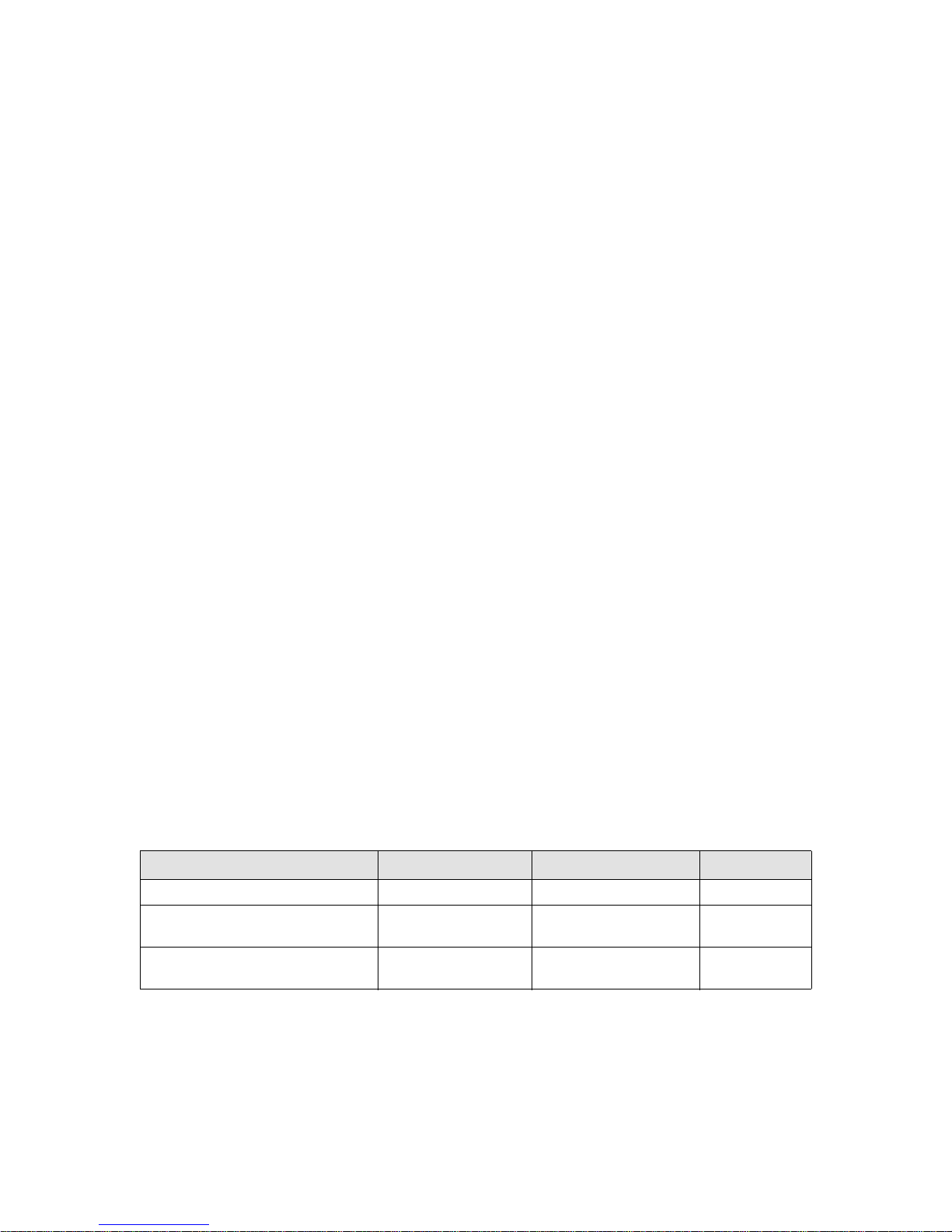
Document History
Title Publication number Summary of changes Date
ServerIron ADX Security Guide 53-1002440-01 New document January, 2012
ServerIron ADX Security Guide 53-1002440-02 Corrections made to ACL
chapter
ServerIron ADX Security Guide 53-1002440-03 Updates made to
documentation.
April, 2012
June, 2012
Page 3

Contents
About This Document
Audience . . . . . . . . . . . . . . . . . . . . . . . . . . . . . . . . . . . . . . . . . . . . . . . xiii
Supported hardware and software . . . . . . . . . . . . . . . . . . . . . . . . . . xiii
Document conventions. . . . . . . . . . . . . . . . . . . . . . . . . . . . . . . . . . . . xiii
Text formatting . . . . . . . . . . . . . . . . . . . . . . . . . . . . . . . . . . . . . . . xiii
Notes, cautions, and danger notices . . . . . . . . . . . . . . . . . . . . . xiv
Notice to the reader . . . . . . . . . . . . . . . . . . . . . . . . . . . . . . . . . . . . . . xiv
Related publications . . . . . . . . . . . . . . . . . . . . . . . . . . . . . . . . . . . . . . xv
Getting technical help. . . . . . . . . . . . . . . . . . . . . . . . . . . . . . . . . . . . . xv
Chapter 1 Network Security
TCP SYN attacks . . . . . . . . . . . . . . . . . . . . . . . . . . . . . . . . . . . . . . . . . . 1
IP TCP syn-proxy. . . . . . . . . . . . . . . . . . . . . . . . . . . . . . . . . . . . . . . . . . . 1
Granular application of syn-proxy feature . . . . . . . . . . . . . . . . . . . . . . 2
Syn-def . . . . . . . . . . . . . . . . . . . . . . . . . . . . . . . . . . . . . . . . . . . . . . . . . . 2
Introduction . . . . . . . . . . . . . . . . . . . . . . . . . . . . . . . . . . . . . . . . . . 2
show server traffic . . . . . . . . . . . . . . . . . . . . . . . . . . . . . . . . . . . . . 2
SYN-def-dont-send-ack . . . . . . . . . . . . . . . . . . . . . . . . . . . . . . . . . 3
show server debug. . . . . . . . . . . . . . . . . . . . . . . . . . . . . . . . . . . . . 3
No response to non-SYN first packet of a TCP flow . . . . . . . . . . . . . . 4
Prioritizing management traffic . . . . . . . . . . . . . . . . . . . . . . . . . . . . . . 5
Protection against attack in hardware . . . . . . . . . . . . . . . . . . . . . 6
Peak BP utilization with TRAP. . . . . . . . . . . . . . . . . . . . . . . . . . . . . . . . 6
Show CPU-utilization command enhancement . . . . . . . . . . . . . . 6
BP utilization threshold . . . . . . . . . . . . . . . . . . . . . . . . . . . . . . . . . 7
MP utilization threshold. . . . . . . . . . . . . . . . . . . . . . . . . . . . . . . . . 7
ServerIron ADX Security Guide v
53-1002440-03
Page 4

Transaction Rate Limit (TRL) . . . . . . . . . . . . . . . . . . . . . . . . . . . . . . . . 7
Understanding transaction rate limit . . . . . . . . . . . . . . . . . . . . . . 7
Configuring transaction rate limit . . . . . . . . . . . . . . . . . . . . . . . . . 8
Configuring the maximum number of rules . . . . . . . . . . . . . . . .12
Saving a TRL configuration . . . . . . . . . . . . . . . . . . . . . . . . . . . . .13
Transaction rate limit command reference . . . . . . . . . . . . . . . .13
Global TRL . . . . . . . . . . . . . . . . . . . . . . . . . . . . . . . . . . . . . . . . . .14
TRL plus security ACL-ID . . . . . . . . . . . . . . . . . . . . . . . . . . . . . . .15
security acl-id . . . . . . . . . . . . . . . . . . . . . . . . . . . . . . . . . . . . . . . .15
Transaction rate limit hold-down value. . . . . . . . . . . . . . . . . . . .15
Displaying TRL rules statistics. . . . . . . . . . . . . . . . . . . . . . . . . . . 15
Displaying TRL rules in a policy. . . . . . . . . . . . . . . . . . . . . . . . . . 15
Displaying IP address with held down traffic . . . . . . . . . . . . . . . 16
Refusing new connections from a specified IP address . . . . . .16
HTTP TRL . . . . . . . . . . . . . . . . . . . . . . . . . . . . . . . . . . . . . . . . . . . . . . . 17
Overview of HTTP TRL . . . . . . . . . . . . . . . . . . . . . . . . . . . . . . . . . . . . . 17
HTTP TRL features . . . . . . . . . . . . . . . . . . . . . . . . . . . . . . . . . . . . 17
Configuring HTTP TRL . . . . . . . . . . . . . . . . . . . . . . . . . . . . . . . . . . . . .18
Configuring HTTP TRL client . . . . . . . . . . . . . . . . . . . . . . . . . . . .18
Configuring HTTP TRL defaults . . . . . . . . . . . . . . . . . . . . . . . . . .19
Sample HTTP TRL configuration . . . . . . . . . . . . . . . . . . . . . . . . .20
Displaying HTTP TRL . . . . . . . . . . . . . . . . . . . . . . . . . . . . . . . . . . . . . .21
Display all HTTP TRL policies. . . . . . . . . . . . . . . . . . . . . . . . . . . .22
Display HTTP TRL policy from index . . . . . . . . . . . . . . . . . . . . . .22
Display HTTP TRL policy client. . . . . . . . . . . . . . . . . . . . . . . . . . .23
Display HTTP TRL policy starting from index . . . . . . . . . . . . . . .23
Display HTTP TRL policy matching a regular expression. . . . . . 24
Display HTTP TRL policy client index (MP) . . . . . . . . . . . . . . . . .24
Display HTTP TRL policy client index (BP). . . . . . . . . . . . . . . . . .25
Display HTTP TRL policy for all client entries (BP) . . . . . . . . . . .26
Downloading an HTTP TRL policy through TFTP . . . . . . . . . . . . . . . .26
HTTP TRL policy commands . . . . . . . . . . . . . . . . . . . . . . . . . . . . . . . .27
Client-name <client-name> monitor-interval . . . . . . . . . . . . . . .27
Client-name <client-name> max-conn . . . . . . . . . . . . . . . . . . . . 27
Client-name <client-name> exceed-action . . . . . . . . . . . . . . . .28
Default monitor-interval. . . . . . . . . . . . . . . . . . . . . . . . . . . . . . . .28
Default max-conn. . . . . . . . . . . . . . . . . . . . . . . . . . . . . . . . . . . . .29
Default exceed-action . . . . . . . . . . . . . . . . . . . . . . . . . . . . . . . . .29
Logging for DoS Attacks . . . . . . . . . . . . . . . . . . . . . . . . . . . . . . . . . . .30
Configuration commands . . . . . . . . . . . . . . . . . . . . . . . . . . . . . .30
show server conn-rate . . . . . . . . . . . . . . . . . . . . . . . . . . . . . . . . . 31
Maximum connections . . . . . . . . . . . . . . . . . . . . . . . . . . . . . . . . . . . . 31
clear statistics dos-attack. . . . . . . . . . . . . . . . . . . . . . . . . . . . . . . . . . 31
Maximum concurrent connection limit per client . . . . . . . . . . . . . . .32
Limiting the number of concurrent connections per client. . . . 32
vi ServerIron ADX Security Guide
53-1002440-03
Page 5

Firewall load balancing enhancements. . . . . . . . . . . . . . . . . . . . . . .34
Enabling firewall strict forwarding. . . . . . . . . . . . . . . . . . . . . . . .34
Enabling firewall VRRPE priority . . . . . . . . . . . . . . . . . . . . . . . . .34
Enabling track firewall group. . . . . . . . . . . . . . . . . . . . . . . . . . . .35
Enabling firewall session sync delay. . . . . . . . . . . . . . . . . . . . . .35
Syn-cookie threshhold trap. . . . . . . . . . . . . . . . . . . . . . . . . . . . . . . . .35
Service port attack protection in hardware. . . . . . . . . . . . . . . . . . . .35
Traffic segmentation . . . . . . . . . . . . . . . . . . . . . . . . . . . . . . . . . . . . . .36
VLAN bridging . . . . . . . . . . . . . . . . . . . . . . . . . . . . . . . . . . . . . . . .36
Considerations when configuring VLAN bridging . . . . . . . . . . . .38
Configuring VLAN bridging. . . . . . . . . . . . . . . . . . . . . . . . . . . . . .38
Displaying VLAN bridge information . . . . . . . . . . . . . . . . . . . . . .39
Traffic segmentation using the use-session-for-vip-mac command41
DNS attack protection. . . . . . . . . . . . . . . . . . . . . . . . . . . . . . . . . . . . .42
Notes: . . . . . . . . . . . . . . . . . . . . . . . . . . . . . . . . . . . . . . . . . . . . . .42
Configuring DNS attack protection . . . . . . . . . . . . . . . . . . . . . . .43
Displaying DNS attack protection information. . . . . . . . . . . . . .46
Chapter 2 Access Control List
How ServerIron processes ACLs. . . . . . . . . . . . . . . . . . . . . . . . . . . . .49
Prior to release 12.3.01 . . . . . . . . . . . . . . . . . . . . . . . . . . . . . . .49
Beginning with release 12.3.01 and later . . . . . . . . . . . . . . . . .49
Rule-based ACLs . . . . . . . . . . . . . . . . . . . . . . . . . . . . . . . . . . . . .50
How fragmented packets are processed . . . . . . . . . . . . . . . . . .51
Default ACL action. . . . . . . . . . . . . . . . . . . . . . . . . . . . . . . . . . . . . . . . 51
Types of IP ACLs. . . . . . . . . . . . . . . . . . . . . . . . . . . . . . . . . . . . . . . . . .52
ACL IDs and entries. . . . . . . . . . . . . . . . . . . . . . . . . . . . . . . . . . . . . . .52
ACL entries and the Layer 4 CAM. . . . . . . . . . . . . . . . . . . . . . . . . . . .53
Aging out of entries in the Layer 4 CAM . . . . . . . . . . . . . . . . . . .53
Displaying the number of Layer 4 CAM entries . . . . . . . . . . . . .53
Specifying the maximum number of CAM entries for rule-based ACLs
54
Configuring numbered and named ACLs. . . . . . . . . . . . . . . . . . . . . .54
Configuring standard numbered ACLs . . . . . . . . . . . . . . . . . . . .55
Configuring extended numbered ACLs . . . . . . . . . . . . . . . . . . . .56
Extended ACL syntax . . . . . . . . . . . . . . . . . . . . . . . . . . . . . . . . . .58
Configuring standard or extended named ACLs . . . . . . . . . . . . 62
Displaying ACL definitions . . . . . . . . . . . . . . . . . . . . . . . . . . . . . .63
Displaying ACLs using keywords . . . . . . . . . . . . . . . . . . . . . . . . .64
Modifying ACLs . . . . . . . . . . . . . . . . . . . . . . . . . . . . . . . . . . . . . . . . . .67
Displaying a list of ACL entries. . . . . . . . . . . . . . . . . . . . . . . . . . . . . .68
Applying an ACLs to interfaces . . . . . . . . . . . . . . . . . . . . . . . . . . . . . .69
Reapplying modified ACLs. . . . . . . . . . . . . . . . . . . . . . . . . . . . . .69
ServerIron ADX Security Guide vii
53-1002440-03
Page 6

ACL logging . . . . . . . . . . . . . . . . . . . . . . . . . . . . . . . . . . . . . . . . . . . . .70
Displaying ACL log entries . . . . . . . . . . . . . . . . . . . . . . . . . . . . . . 71
Displaying ACL statistics for flow-based ACLs . . . . . . . . . . . . . .72
Clearing flow-based ACL statistics . . . . . . . . . . . . . . . . . . . . . . .72
Dropping all fragments that exactly match a flow-based ACL . . . . . 72
Clearing the ACL statistics. . . . . . . . . . . . . . . . . . . . . . . . . . . . . .73
Enabling ACL filtering of fragmented packets. . . . . . . . . . . . . . . . . .73
Filtering fragmented packets for rule-based ACLs. . . . . . . . . . .73
Enabling hardware filtering for packets denied by flow-based ACLs75
Enabling strict TCP or UDP mode for flow-based ACLs. . . . . . . . . . . 76
Enabling strict TCP mode . . . . . . . . . . . . . . . . . . . . . . . . . . . . . . 76
Enabling strict UDP mode . . . . . . . . . . . . . . . . . . . . . . . . . . . . . .77
Configuring ACL packet and flow counters. . . . . . . . . . . . . . . . .78
ACLs and ICMP . . . . . . . . . . . . . . . . . . . . . . . . . . . . . . . . . . . . . . . . . .79
Using flow-based ACLs to filter ICMP packets based on the IP packet
length . . . . . . . . . . . . . . . . . . . . . . . . . . . . . . . . . . . . . . . . . . . . . .79
ICMP filtering with flow-based ACLs . . . . . . . . . . . . . . . . . . . . . .79
Using ACLs and NAT on the same interface (flow-based ACLs) . . . .82
Displaying ACL bindings . . . . . . . . . . . . . . . . . . . . . . . . . . . . . . . . . . .83
Troubleshooting rule-based ACLs. . . . . . . . . . . . . . . . . . . . . . . . . . . .83
. . . . . . . . . . . . . . . . . . . . . . . . . . . . . . . . . . . . . . . . . . . . . . . . . . . . . . .84
Chapter 3 IPv6 Access Control Lists
IACL overview. . . . . . . . . . . . . . . . . . . . . . . . . . . . . . . . . . . . . . . . . . . .85
Configuration Notes. . . . . . . . . . . . . . . . . . . . . . . . . . . . . . . . . . .86
Processing of IPv6 ACLs . . . . . . . . . . . . . . . . . . . . . . . . . . . . . . .86
Configuring an IPv6 ACL . . . . . . . . . . . . . . . . . . . . . . . . . . . . . . . 87
Applying an IPv6 ACL to an interface . . . . . . . . . . . . . . . . . . . . .93
Displaying ACLs . . . . . . . . . . . . . . . . . . . . . . . . . . . . . . . . . . . . . .94
Displaying ACLs bound to an interface. . . . . . . . . . . . . . . . . . . .94
Using an ACL to Restrict SSH Access. . . . . . . . . . . . . . . . . . . . . . . . .94
Using an ACL to Restrict Telnet Access . . . . . . . . . . . . . . . . . . . . . . .95
Logging IPv6 ACLs. . . . . . . . . . . . . . . . . . . . . . . . . . . . . . . . . . . . . . . .95
. . . . . . . . . . . . . . . . . . . . . . . . . . . . . . . . . . . . . . . . . . . . . . . . . . . . . . .95
Chapter 4 Network Address Translation
Introduction . . . . . . . . . . . . . . . . . . . . . . . . . . . . . . . . . . . . . . . . . . . . . 97
Configuring NAT. . . . . . . . . . . . . . . . . . . . . . . . . . . . . . . . . . . . . . . . . . 97
Configuring static NAT . . . . . . . . . . . . . . . . . . . . . . . . . . . . . . . . .98
Configuring dynamic NAT. . . . . . . . . . . . . . . . . . . . . . . . . . . . . . .98
NAT configuration examples . . . . . . . . . . . . . . . . . . . . . . . . . . . .99
PAT . . . . . . . . . . . . . . . . . . . . . . . . . . . . . . . . . . . . . . . . . . . . . . . . . . .103
Forwarding packets without NAT translation. . . . . . . . . . . . . . . . . .103
viii ServerIron ADX Security Guide
53-1002440-03
Page 7

Translation timeouts . . . . . . . . . . . . . . . . . . . . . . . . . . . . . . . . . . . . .104
Configuring the NAT translation aging timer . . . . . . . . . . . . . .104
Stateless static IP NAT . . . . . . . . . . . . . . . . . . . . . . . . . . . . . . . . . . .105
Redundancy. . . . . . . . . . . . . . . . . . . . . . . . . . . . . . . . . . . . . . . . . . . .105
Enabling IP NAT . . . . . . . . . . . . . . . . . . . . . . . . . . . . . . . . . . . . .106
Enabling static NAT redundancy . . . . . . . . . . . . . . . . . . . . . . . .106
Enabling dynamic NAT redundancy . . . . . . . . . . . . . . . . . . . . .107
Displaying NAT information. . . . . . . . . . . . . . . . . . . . . . . . . . . . . . . .107
Displaying NAT statistics . . . . . . . . . . . . . . . . . . . . . . . . . . . . . .108
Displaying NAT translation. . . . . . . . . . . . . . . . . . . . . . . . . . . . .110
Displaying NAT redundancy information. . . . . . . . . . . . . . . . . .111
Displaying VRRPE information . . . . . . . . . . . . . . . . . . . . . . . . .112
Clearing NAT entries from the table. . . . . . . . . . . . . . . . . . . . . . . . .112
Chapter 5 Syn-Proxy and DoS Protection
Understanding Syn-Proxy . . . . . . . . . . . . . . . . . . . . . . . . . . . . . . . . .113
Syn-Proxy auto control . . . . . . . . . . . . . . . . . . . . . . . . . . . . . . . .113
Difference between ServerIron ADX and JetCore Syn-Proxy Behavior
113
Configuring Syn-Proxy . . . . . . . . . . . . . . . . . . . . . . . . . . . . . . . . . . . .114
Setting a minimum MSS value for SYN-ACK packets . . . . . . . 117
Configuring Syn-Proxy auto control . . . . . . . . . . . . . . . . . . . . . .120
Displaying Syn-Proxy Commands . . . . . . . . . . . . . . . . . . . . . . .121
DDoS protection . . . . . . . . . . . . . . . . . . . . . . . . . . . . . . . . . . . . . . . .124
Configuring a security filter . . . . . . . . . . . . . . . . . . . . . . . . . . . .125
Configuring a Generic Rule . . . . . . . . . . . . . . . . . . . . . . . . . . . .125
Configuring a rule for common attack types. . . . . . . . . . . . . .127
Configuring a rule for ip-option attack types . . . . . . . . . . . . . .129
Configuring a rule for icmp-type options . . . . . . . . . . . . . . . . .130
Configuring a rule for IPv6 ICMP types. . . . . . . . . . . . . . . . . . .131
Configuring a rule for IPv6 ext header types . . . . . . . . . . . . . .132
Binding the filter to an interface. . . . . . . . . . . . . . . . . . . . . . . .133
Clearing DOS attack statistics. . . . . . . . . . . . . . . . . . . . . . . . . .133
Clearing all DDOS Filter & Attack Counters . . . . . . . . . . . . . . .133
Logging for DoS attacks. . . . . . . . . . . . . . . . . . . . . . . . . . . . . . .133
Displaying security filter statistics . . . . . . . . . . . . . . . . . . . . . .134
Address-sweep and port-scan logging . . . . . . . . . . . . . . . . . . .134
ServerIron ADX Security Guide ix
53-1002440-03
Page 8

Chapter 6 Secure Socket Layer (SSL) Acceleration
SSL overview . . . . . . . . . . . . . . . . . . . . . . . . . . . . . . . . . . . . . . . . . . .135
Public Key Infrastructure (PKI) . . . . . . . . . . . . . . . . . . . . . . . . .135
Asymmetric cryptography . . . . . . . . . . . . . . . . . . . . . . . . . . . . .136
Certificate Authority (CA) . . . . . . . . . . . . . . . . . . . . . . . . . . . . . .136
Certificate Revocation List (CRL) . . . . . . . . . . . . . . . . . . . . . . .136
Cipher suite . . . . . . . . . . . . . . . . . . . . . . . . . . . . . . . . . . . . . . . .136
Digital certificate . . . . . . . . . . . . . . . . . . . . . . . . . . . . . . . . . . . .136
Digital signature. . . . . . . . . . . . . . . . . . . . . . . . . . . . . . . . . . . . .136
Key . . . . . . . . . . . . . . . . . . . . . . . . . . . . . . . . . . . . . . . . . . . . . . .136
Key pair. . . . . . . . . . . . . . . . . . . . . . . . . . . . . . . . . . . . . . . . . . . .136
Private key . . . . . . . . . . . . . . . . . . . . . . . . . . . . . . . . . . . . . . . . .136
Public key . . . . . . . . . . . . . . . . . . . . . . . . . . . . . . . . . . . . . . . . . .137
SSL acceleration on the ServerIron ADX . . . . . . . . . . . . . . . . . . . . .137
SSL Termination Mode . . . . . . . . . . . . . . . . . . . . . . . . . . . . . . .137
SSL Proxy Mode . . . . . . . . . . . . . . . . . . . . . . . . . . . . . . . . . . . .138
ServerIron ADX SSL . . . . . . . . . . . . . . . . . . . . . . . . . . . . . . . . . .138
Configuring SSL on a ServerIron ADX . . . . . . . . . . . . . . . . . . . . . . .140
Obtaining a ServerIron ADX keypair file . . . . . . . . . . . . . . . . . .140
Certificate management . . . . . . . . . . . . . . . . . . . . . . . . . . . . . .141
Converting certificate formats. . . . . . . . . . . . . . . . . . . . . . . . . .147
Importing keys and certificates. . . . . . . . . . . . . . . . . . . . . . . . .148
Support for SSL renegotiation. . . . . . . . . . . . . . . . . . . . . . . . . .164
Basic SSL profile configuration . . . . . . . . . . . . . . . . . . . . . . . . . . . .164
Specifying a keypair file. . . . . . . . . . . . . . . . . . . . . . . . . . . . . . .165
Specifying a cipher suite . . . . . . . . . . . . . . . . . . . . . . . . . . . . . .165
Specifying a certificate file . . . . . . . . . . . . . . . . . . . . . . . . . . . .166
Advanced SSL profile configuration. . . . . . . . . . . . . . . . . . . . . . . . .166
Configuring client authentication . . . . . . . . . . . . . . . . . . . . . . .166
Enabling session caching . . . . . . . . . . . . . . . . . . . . . . . . . . . . .170
Configuring session cache size. . . . . . . . . . . . . . . . . . . . . . . . .170
Configuring a session cache timeout . . . . . . . . . . . . . . . . . . . . 171
Enabling SSL Version 2 . . . . . . . . . . . . . . . . . . . . . . . . . . . . . . . 171
Enabling close notify . . . . . . . . . . . . . . . . . . . . . . . . . . . . . . . . . 171
Disabling certificate verification . . . . . . . . . . . . . . . . . . . . . . . . 171
Enabling a ServerIron ADX SSL to respond with renegotiation
headers. . . . . . . . . . . . . . . . . . . . . . . . . . . . . . . . . . . . . . . . . . . .172
Configuring Real and Virtual Servers for SSL Termination and Proxy Mode
172
Configuring Real and Virtual Servers for SSL Termination Mode173
Configuring Real and Virtual Servers for SSL Proxy Mode . . . 174
Configuration Examples for SSL Termination and Proxy Modes . . 176
Configuring SSL Termination Mode . . . . . . . . . . . . . . . . . . . . . 176
Configuring SSL Proxy Mode . . . . . . . . . . . . . . . . . . . . . . . . . . .177
TCP configuration issues with SSL Terminate and SSL Proxy.178
Other protocols supported for SSL . . . . . . . . . . . . . . . . . . . . . .184
Configuring the system max values . . . . . . . . . . . . . . . . . . . . .185
x ServerIron ADX Security Guide
53-1002440-03
Page 9

SSL debug and troubleshooting commands. . . . . . . . . . . . . . . . . .187
Diagnostics. . . . . . . . . . . . . . . . . . . . . . . . . . . . . . . . . . . . . . . . .187
Displaying SSL information . . . . . . . . . . . . . . . . . . . . . . . . . . . .188
Displaying the status of a CRL record . . . . . . . . . . . . . . . . . . .191
Displaying socket information . . . . . . . . . . . . . . . . . . . . . . . . . . . . .199
Displaying SSL Statistics information. . . . . . . . . . . . . . . . . . . .201
Displaying TCP IP information . . . . . . . . . . . . . . . . . . . . . . . . . .205
ASM SSL dump commands. . . . . . . . . . . . . . . . . . . . . . . . . . . .209
ServerIron ADX Security Guide xi
53-1002440-03
Page 10

xii ServerIron ADX Security Guide
53-1002440-03
Page 11

About This Document
Audience
This document is designed for system administrators with a working knowledge of Layer 2 and
Layer 3 switching and routing.
If you are using a Brocade Layer 3 Switch, you should be familiar with the following protocols if
applicable to your network – IP, RIP, OSPF, BGP, ISIS, IGMP, PIM, DVMRP, and VRRP.
Supported hardware and software
Although many different software and hardware configurations are tested and supported by
Brocade Communications Systems, Inc. for 12.3 documenting all possible configurations and
scenarios is beyond the scope of this document.
The following hardware platforms are supported by this release of this guide:
• ServerIron ADX 1000
• ServerIron ADX 4000
• ServerIron ADX 8000
• ServerIron ADX 10000
Document conventions
This section describes text formatting conventions and important notice formats used in this
document.
Text formatting
The narrative-text formatting conventions that are used are as follows:
ServerIron ADX Security Guide xiii
53-1002440-03
Page 12
NOTE
CAUTION
DANGER
bold text Identifies command names
Identifies the names of user-manipulated GUI elements
Identifies keywords
Identifies text to enter at the GUI or CLI
italic text Provides emphasis
Identifies variables
Identifies document titles
code text Identifies CLI output
For readability, command names in the narrative portions of this guide are presented in bold: for
example, show version.
Notes, cautions, and danger notices
The following notices and statements are used in this manual. They are listed below in order of
increasing severity of potential hazards.
A note provides a tip, guidance or advice, emphasizes important information, or provides a reference
to related information.
A Caution statement alerts you to situations that can be potentially hazardous to you or cause
damage to hardware, firmware, software, or data.
A Danger statement indicates conditions or situations that can be potentially lethal or extremely
hazardous to you. Safety labels are also attached directly to products to warn of these conditions
or situations.
Notice to the reader
This document may contain references to the trademarks of the following corporations. These
trademarks are the properties of their respective companies and corporations.
These references are made for informational purposes only.
Corporation Referenced Trademarks and Products
Sun Microsystems Solaris
xiv ServerIron ADX Security Guide
53-1002440-03
Page 13

Corporation Referenced Trademarks and Products
Microsoft Corporation Windows NT, Windows 2000
The Open Group Linux
Related publications
The following Brocade documents supplement the information in this guide:
• Release Notes for ServerIron Switch and Router Software TrafficWorks 12.2.00
• ServerIron ADX Graphical User Interface
• ServerIron ADX Server Load Balancing Guide
• ServerIron ADX Advanced Server Load Balancing Guide
• ServerIron ADX Global Server Load Balancing Guide
• ServerIron ADX Security Guide
• ServerIron ADX Administration Guide
• ServerIron ADX Switching and Routing Guide
• ServerIron ADX Firewall Load Balancing Guide
• ServerIron ADX Chassis Hardware Installation Guide
• Ironware MIB Reference Manual
Getting technical help
To contact Technical Support, got to http://www.brocade.com/services-support/index.page for the
latest e-mail and telephone contact information..
ServerIron ADX Security Guide xv
53-1002440-03
Page 14

xvi ServerIron ADX Security Guide
53-1002440-03
Page 15

Chapter
NOTE
Network Security
TCP SYN attacks
ServerIron software contains many intrusion detection and prevention capabilities. The ServerIron
can be configured to defend against a variety of TCP SYN attacks, Denial of Service (DoS) attacks,
and Smurf attacks.
TCP SYN attacks disrupt normal traffic flow by exploiting the way TCP connections are established.
When a normal TCP connection occurs, the connecting host first sends a TCP SYN packet to the
destination host. The destination host (actually the ServerIron, acting as an intermediary between
the source and destination hosts) responds with a SYN ACK packet. The connecting host then
returns an ACK packet. This process, known as a “TCP three-way handshake”, establishes the TCP
connection.
A TCP SYN attack floods a host with TCP SYN packets. For each of these TCP SYN packets, the
ServerIron responds with a SYN ACK packet and adds an entry to its session table. However, no
ACK packet is actually sent back, so the connection is incomplete. If the attacker sends enough
TCP SYN packets, the session table fills up with incomplete connections, and service can be denied
to legitimate TCP connections.
syn-proxy
1
IP TCP syn-proxy
Configure the ip tcp syn-proxy command as shown in the following.
1. Configure syn-proxy in the global mode.
ServerIronADX(config)# ip tcp syn-proxy
Syntax: ip tcp syn-proxy
You must configure ip tcp syn-proxy command only at the global level, to turn on and off the
global syn-proxy flag.
2. Enable syn-proxy on each interface handling inbound SYN requests (no change here).
ServerIronADX(config)#interface e 3/1
ServerIronADX(config-if-3/1)# ip tcp syn-proxy in
Usage guidelines:
• The default value for a valid ACK time is 32 seconds and is not user configurable.
• If you enter a value, it is ignored. The command remains in the config file the way you enter it,
in case you need to downgrade to the previous release.
ServerIron ADX Security Guide 1
53-1002440-03
Page 16

Granular application of syn-proxy feature
NOTE
1
• ServerIron may accept the ACK during 33 seconds to 64 seconds due to the syn-proxy
algorithm, but it does not accept the ACK after 64 seconds.
• If you enter a value for the ip tcp syn-proxy <value> command from the CLI or upgrade from an
older release such as 09.4.x to 09.5.2a with the ip tcp syn-proxy <value> command in the
config file, you receive the following warning message.
Warning: The value 10 is being ignored.
Default ACK validate time of 32 seconds will be used.
To change the MSL value, issue 'server msl <value>'.
Granular application of syn-proxy feature
This feature applies to ServerIron ADX Syn-Proxy. When this feature is enabled, traffic destined to a
virtual server IP is denied if the destination port is not defined under any of the virtual server
definitions.
This feature prevents ServerIron ADX from responding with TCP SYN-ACK to TCP SYN for ports not
defined under VIP.
Use the following command to validate traffic against a configured virtual port.
ServerIronADX(config)# server syn-cookie-check-vport
Syn-def
Syntax: [no] server syn-cookie-check-vport
Introduction
Use SYN-def (also known as SYN-Defense) to protect the hosts behind the ServerIron (not the
ServerIron itself) by the ServerIron to complete the TCP three-way handshake on behalf of a
connecting client. There is no SYN-cookie functionality with SYN-def.
SYN-Defense is recommened for only where Direct Server Return (DSR) is used. DSR is not
supported with SYN-proxy and is supported with SYN-def. For non DSR scenarios, use Syn-Proxy only.
show server traffic
Use the show server traffic command to display information about the number of times the
incomplete connection threshold was reached.
2 ServerIron ADX Security Guide
53-1002440-03
Page 17

Syn-def
ServerIronADX# show server traffic
Client->Server = 0 Server->Client = 0
Drops = 0 Aged = 0
Fw_drops = 0 Rev_drops = 0
FIN_or_RST = 0 old-conn = 0
Disable_drop = 0 Exceed_drop = 0
Stale_drop = 0 Unsuccessful = 0
TCP SYN-DEF RST = 0 Server Resets = 0
Out of Memory = 0 Out of Memory = 0
1
The last line contains information relevant to the incomplete connection threshold. The TCP
SYN-DEF RST field displays the number of times the incomplete connection threshold was reached.
The Server Resets field displays the number of times the ServerIron sent a TCP RESET packet to
the destination real server.
SYN-def-dont-send-ack
The SYN-def feature allows the ServerIron to complete the TCP three-way handshake on behalf of a
connecting client. When a connecting client sends a TCP SYN to a server, the ServerIron forwards
the SYN to the real server, then forwards the SYN ACK from the server to the client. Next, the
ServerIron sends an ACK to the real server, completing the three-way handshake on behalf of the
connecting client. This action allows the real server to move the connection from its pending
connection queue to its established (and much larger) connection queue.
Use the server syn-def-dont-send-ack command to prevent the ServerIron from sending the ACK to
the real server to complete the three-way handshake.
Example
ServerIronADX(config)#server syn-def-dont-send-ack
show server debug
Use the show server debug command to display information about the configuration, as shown in
the following example.
ServerIron ADX Security Guide 3
53-1002440-03
Page 18

No response to non-SYN first packet of a TCP flow
SLB-chassis1/1#show server debug
Generic Deug Info
BP Distribution = Enabled JetCore = No
No of BPs = 3 No of Partner BPs = 0
Partner Chassis MAC = 0000.0000.0000
Partner BP1 MAC = 0000.0000.0000 Partner BP2 MAC = 0000.0000.0000
Partner BP3 MAC = 0000.0000.0000 Partner BP4 MAC = 0000.0000.0000
Partner BP5 MAC = 0000.0000.0000 Partner BP6 MAC = 0000.0000.0000
Server Load Balancing Debug Info
Total Get = 3 Total Free = 0
Get Fails = 0 Get Buffer failure = 0
Forward Sp = 0 Reverse Sp = 0
Bad creates = 0 TCP Resets = 0
Fw resets = 0 Rev Resets = 0
Double Free = 0 Error = 0
Free inv Sess Idx = 0 Free list Idx inv = 0
Cache-Reassigns = 0 Trans-Denied = 0
Multi Path Fwd Use = 0 Multi Path Rev Use = 0
Bad non-owner = 0 Select Fwall = 0
FTP-trans-error = 0 Cache track-error = 0
Fw tcp inside move = 0 Fw udp inside move = 0
Fw SYNC delayed = 0 ownership contention = 0
FW stale to conns = 0 FW stale to delq con = 0
FW stale from conns = 0 FW stale from delq c = 0
FW stale from nuke c = 0 Sac frwds = 0
Unxpectd udata = 0 Unxpectd udata(def) = 0
Client->Server = 0 Server->Client = 0
Drops = 0 Aged = 0
Fw_drops = 0 Rev_drops = 0
FIN_or_RST = 0 old-conn = 0
Disable_drop = 0 Exceed_drop = 0
Stale_drop = 0 Unsuccessful = 0
SYN def/proxy RST = 0 Server Resets = 0
Out of Memory = 0 Out of Memory = 0
last conn rate = 0 max conn rate = 0
last TCP attack rate = 0 max TCP attack rate = 0
fast vport found = 0 fast vport n found = 0
Fwd to non-static FI = 0 Dup stale SYN = 0
TCP forward FIN = 0 TCP reverse FIN = 0
Fast path FWD FIN = 0 Fast path REV FIN = 0
Fast path SLB SYN = 0 Dup SYN after FIN = 0
Duplicate SYN = 0 Duplicate sessions = 0
TCP ttl FIN recvd = 0 TCP ttl reset recvd = 0
Sessions in DEL_Q = 0 Sess force deleted = 0
Fwd sess not found = 0 sess already in delQ = 0
Sess rmvd from delQ = 0
Fragment buf full er = 0 Incoming TCP cksum e = 0
New sess sync sent = 0 New sess sync recvd = 0
L4 msg sent = 0 L4 msg recvd = 0
foundry packet sent = 0 ipc packet sent = 2818942
TCP SYN received = 0 TCP SYN dropped = 0
TCP SYN to MP = 0 TCP SYN ACK to MP = 0
TCP SYN ACK received = 0 TCP SYN ACK dropped = 0
TCP pkt received = 0 TCP pkt dropped = 0
TCP pkt to MP = 0 PBSLB tftp status = In progres
Avail. Sessions = 1999996 Total Sessions = 2000000
Hash size = 200001
Total C->S Conn = 0 Total S->C Conn = 0
Total Reassign = 0 Unsuccessful Conn = 0
Server State - 0: diasbled, 1:enabled, 2:failed, 3:test, 4:suspect, 5:grace_dn, 6:active
Real Server St CurrConn TotConn TotRevConn CurrSess PeakConn
R1 1 0/0/0 0 0 0 0
rs1 1 0/0/0 0 0 0 0
1
No response to non-SYN first packet of a TCP flow
ServerIron can remain passive for non-SYN packet in the beginning of the flow. The default
behavior is to send TCP RESET to client when a non-SYN packet is received in the beginning.
4 ServerIron ADX Security Guide
53-1002440-03
Page 19

By default, when ServerIron ADX receives TCP packet that is destined to VIP and there is no session
NOTE
match then it sends TCP reset to the sender. However, if one desires to remain passive then the
above feature can be enabled.
To not send the reset packet, use the following command.
ServerIronADX(config)# server reset-on-syn-only
To remove the configuration, use the following command.
ServerIronADX(config)# no server reset-on-syn-only
Syntax: [no] server reset-on-syn-only
Prioritizing management traffic
ServerIron ADX software allows the system to prioritize traffic destined to the management IP
address in order to facilitate uninterrupted access to the ServerIron switch even under heavy load
conditions. This feature allows you to prioritize management traffic based on the following.
1. Client IP address/subnet
2. Protocol (TCP/UDP/IP) and
Prioritizing management traffic
1
3. TCP or UDP port number
With this feature turned on, the specified traffic is directly forwarded to the Management Module in
hardware. In the following example, traffic from the source subnet 1.1.1.1 and destined to
management IP 10.45.16.104 for TCP port 22 (SSH) is prioritized.
ServerIronADX(config)# server prioritize-mgmt-traffic 1.1.1.1 255.255.255.0
10.45.16.104 6 22
Syntax: server prioritize-mgmt-traffic <source ip> <mask> <destination ip> [<protocol>] [<port>]
The <source ip> variable specifies the Source IP address.
The <mask> variable specifies the Mask for the source IP address.
The <destination ip> variable specifies the Destination management IP address. The destination IP
address must already be configured on the ServerIron ADX. If the IP address is not configured, the
command is rejected.
The <protocol> variable specifies any protocol.
The <port> variable specifies a TCP or UDP port.
It is also possible to prioritize management traffic from any source ip as shown in the example
below.
ServerIronADX(config)# server prioritize-mgmt-traffic any 10.45.16.104 6 22
Syntax: [no] server prioritize-mgmt-traffic any <destination ip> [<protocol>] [<port>]
The prioritizing management traffic feature should not be enabled for a ServerIron ADX router VE
address if this interface is used for source-NAT as that would break the SLB traffic flow.
Refer to the following examples.
Prioritization of TCP port 80 traffic to management IP 200.1.1.1
ServerIron ADX Security Guide 5
53-1002440-03
Page 20

Peak BP utilization with TRAP
NOTE
1
ServerIronADX# server prioritize-mgmt-traffic 1.1.1.1 255.255.255.0 200.1.1.1 6
80
Prioritization of TCP port 80 traffic to management IP 200.1.1.1 from any source IP address
ServerIronADX# server prioritize-mgmt-traffic any 200.1.1.1 6 80
Prioritization of UDP port 2222 traffic to management IP 200.1.1.1
ServerIronADX# server prioritize-mgmt-traffic 1.1.1.1 255.255.255.0 200.1.1.1 17
2222
Prioritization of IP protocol 89 (OSPF) traffic to management IP 200.1.1.1
ServerIronADX# server prioritize-mgmt-traffic 1.1.1.1 255.255.255.0 200.1.1.1 89
Protection against attack in hardware
ServerIron ADX allows for protection against attack in hardware without impacting MP or BP CPU
utilization. Configure the server the drop-all-mgmt-access command to drop all traffic destined to a
specified management IP address.
The following command drops all traffic destined to the management IP address 10.45.16.104.
ServerIronADX(config)# server drop-all-mgmt-access 10.45.16.104
Syntax: [no] server drop-all-mgmt-access <destination ip>
For a router, the destination IP address is the physical or ve interface IP address For a switch, the
destination IP address is the management IP address.
The server drop-all-mgmt-access feature when used in combination with the server
prioritize-mgmt-traffic feature allows you to prioritize valid traffic while blocking unwanted traffic
destined to the management IP address.
For example, with the following configuration, only ssh, telnet and http traffic destined to
management IP address 10.45.16.104 will be prioritized and all other traffic destined to
10.45.16.104 will be dropped.
ServerIronADX(config)#server prioritize-mgmt-traffic 1.1.1.1 255.255.255.0
10.45.16.104 6 22
ServerIronADX(config)#server prioritize-mgmt-traffic 1.1.1.1 255.255.255.0
10.45.16.104 6 23
ServerIronADX(config)#server prioritize-mgmt-traffic 1.1.1.1 255.255.255.0
10.45.16.104 6 80
ServerIronADX(config)#server drop-all-mgmt-access 10.45.16.104
Peak BP utilization with TRAP
Show CPU-utilization command enhancement
The show cpu-utilization command displays CPU utilization peaks since the system boot or the last
reset of counters (using the clear cpu utilization command).
The command, clear cpu-utilization, on both the MP and the BP is used to reset the counter.
6 ServerIron ADX Security Guide
53-1002440-03
Page 21

Transaction Rate Limit (TRL)
BP utilization threshold
The bp-utilization-threshold command allows you to specify a threshold for BP CPU utilization.
Define this command under the global configuration mode.
When the threshold is exceeded, the event is logged and a trap is sent. The log and trap are
rate-limited to one per two minutes.
The command takes a percentage string as parameter.
Example
ServerIronADX(config)# bp-utilization-threshold 80.5%
Syntax: bp-utilization-threshold <percentage>
MP utilization threshold
The mp-utilization-threshold command specifies a threshold for BP CPU utilization. Define this
command under the global configuration mode.
When the threshold is exceeded, the event is logged and a trap is sent. The log and trap are
rate-limited to one every two minutes.
1
The command takes a percentage string as parameter.
Example
ServerIronADX(config)# mp-utilization-threshold 80.5%
Syntax: mp-utilization-threshold <percentage>
Transaction Rate Limit (TRL)
Transaction Rate Limit, allows the ServerIron ADX to monitor and limit traffic from any one IP
address.
Understanding transaction rate limit
Transaction Rate Limit counts the number of transactions received from any one IP address. If the
transaction count exceeds a specified threshold value, traffic from that IP address is held and not
processed for a specified number of minutes.
Transaction rate limit provides the flexibility to specify different configurations for different clients,
based on the client IP address/prefix.
Transaction rate limit provides the following benefits:
• Ability to apply a default transaction rate limit value to all clients, while maintaining an
exception list.
• Ability to apply a different transaction rate limit rate per client IP or prefix.
• Ability to exclude specific IP addresses or prefixes from transaction rate limit and maintain an
exclude list.
• Ability to apply transaction rate limit to traffic coming to a specific VIP only.
ServerIron ADX Security Guide 7
53-1002440-03
Page 22

Transaction Rate Limit (TRL)
1
• Ability to operate on a per VIP basis, whereby a different rate limit can be applied to traffic
Configuring transaction rate limit
To enable transaction rate limit, you must configure parameters for each client address/prefix and
apply the transaction rate limit configuration to a specific VIP.
Prerequisites
Before you can configure transaction rate limit, you must configure a virtual server. The following
example shows how to configure a virtual server.
ServerIronADX> enable
ServerIronADX# config terminal
ServerIronADX(config)# server virtual-name-or-ip bwVIP 1.1.1.33
Syntax: [no] server virtual-name-or-ip <vip-name-or-address> <ip address>
Configure transaction rate limit rule set
coming to a different VIP.
The transaction rate limit parameters are grouped into a set and each set is associated with a
name. To create a set of transaction rate limit rules, follow these steps.
1. Enable privileged EXEC mode.
ServerIronADX> enable
2. Enter global configuration mode.
ServerIronADX# configure terminal
3. Configure name of a transaction rate limit rule set and enter client transaction rate limit
configuration mode.
ServerIronADX(config)#client-trans-rate-limit tcp TRL1
Syntax: [no] client-trans-rate-limit tcp | udp | icmp <name>
4. Specify the trl keyword for client subnet and set connection rate.
For IPv4:
ServerIronADX(config-client-trl-trl1)# trl 100.1.1.0 255.255.255.0
monitor-interval 3 conn-rate 10 hold-down-time 1
For IPv6:
ServerIronADX(config-client-trl-trl1)# trl 100::1/128 monitor-interval 3
conn-rate 10 hold-down-time 1
Syntax: [no] trl { <client-IPv4> <client-mask> | <client-IPv6> <prefix> } monitor-interval
<mon-value> conn-rate <con-value> hold-down-time <hold-down-value>
Configure transaction rate limit to exclude a client
You can configure a client address/prefix to be excluded from transaction rate limiting within a
transaction rate limit configuration group.
To exclude a client from transaction rate limit, follow these steps.
8 ServerIron ADX Security Guide
53-1002440-03
Page 23

Transaction Rate Limit (TRL)
1. Enable privileged EXEC mode.
ServerIronADX> enable
2. Enter global configuration mode.
ServerIronADX# configure terminal
3. Specify the name of the transaction rate limit rule set and enter client transaction rate limit
configuration mode.
ServerIronADX(config)# client-trans-rate-limit tcp TRL1
Syntax: [no] client-trans-rate-limit tcp | udp | icmp <name>
4. Specify the trl parameter for the client subnet and the exclude keyword.
For IPv4:
ServerIronADX(config-client-trl-TRL1)# trl 100.1.1.0 255.255.255.0 exclude
For IPv6:
ServerIronADX(config-client-trl-TRL1)# trl 300::1/128 exclude
Syntax: [no] trl { <client-IPv4> <client-mask> | <client-IPv6> <prefix> } exclude
1
Configure a transaction rate limit default
You can specify a default transaction rate limit configuration for all other clients that are not
explicitly configured. To create a transaction rate limit default for a group, follow these steps.
1. Enable privileged EXEC mode.
ServerIronADX> enable
2. Enter global configuration mode.
ServerIronADX# configure terminal
3. Specify name of transaction rate limit rule set and enter client transaction rate limit
configuration mode.
ServerIronADX(config)# client-trans-rate-limit tcp TRL1
Syntax: [no] client-trans-rate-limit tcp | udp | icmp <name>
4. Specify the default trl parameter for this group.
ServerIronADX(config-client-trl)# trl default monitor-interval 3 conn-rate 10
hold-down-time 1
Syntax: [no] trl default monitor-interval <mon-value> conn-rate <con-value> hold-down-time
<hold-down-value>
ServerIron ADX Security Guide 9
53-1002440-03
Page 24

Transaction Rate Limit (TRL)
1
Configure transaction rate limit for pass through traffic
You can configure transaction rate limit for traffic that is not going to a virtual server. You can
configure only one group for pass through traffic.
To create a transaction rate limit group for pass through traffic, follow these steps.
1. Enable privileged EXEC mode.
2. Enter global configuration mode.
3. Specify name of BW rule set and enter client bandwidth configuration mode.
4. Specify the trl parameter for the client subnet and set a connection rate.
ServerIronADX> enable
ServerIronADX# configure terminal
ServerIronADX(config)# client-trans-rate-limit tcp default
Syntax: [no] client-trans-rate-limit tcp | udp | icmp default
For IPv4:
ServerIronADX(config-client-trl)#trl 100.1.1.0 255.255.255.0 monitor-interval
3 conn-rate 10 hold-down-time 1
For IPv6:
ServerIronADX(config-client-trl)#trl 300:11/128 monitor-interval 3 conn-rate
10 hold-down-time 1
Syntax: [no] trl { <client-IPv4> <client-mask> | <client-IPv6> <prefix> } monitor-interval
<mon-value> conn-rate <con-value> hold-down-time <hold-down-value>
5. The transaction rate limit policy pertaining to the protocol and the port must be applied to
either the physical or the virtual interface for pass through traffic. This will ensure that the
traffic is brought to the application processor (BP) for rate-limitation.
Applying policy on physical interface
ServerIronADX(config) # interface eth 1/1
ServerIronADX(config-if-1/1) # ip tcp trans-rate 80
Applying policy on virtual interface
ServerIronADX(config) # interface ve 20
ServerIronADX(config-vif-20) # ip udp trans-rate 53
Syntax: [no} ip tcp | udp trans-rate <ports>
Syntax: [no} ip icmp trans-rate
The <ports> parameter specifies one or more TCP or UDP ports to monitor. You can monitor up
to four ports.
Apply transaction rate limit to a VIP
After configuring transaction rate limit, you must bind transaction rate limit to a VIP. To enable
transaction rate limit, follow these steps.
1. Enable privileged EXEC mode.
ServerIronADX> enable
10 ServerIron ADX Security Guide
53-1002440-03
Page 25

Transaction Rate Limit (TRL)
NOTE
1
2. Enter global configuration mode.
ServerIronADX# configure terminal
3. Specify server virtual-name-or-ip command and VIP name to enter virtual server configuration
mode.
ServerIronADX(config)# server virtual-name-or-ip bwVIP
Syntax: [no] server virtual-name-or-ip <name-or-address>
4. Specify the BW parameter and BW rule set.
ServerIronADX(config-vs-bwVIP)# client-trans-rate-limit trl
Syntax: [no] client-trans-rate-limit <name>
5. The transaction rate limit policy pertaining to the protocol and the port must be applied to
either the physical or the virtual interface for traffic hitting to Virtual IP.
Applying policy on physical interface
ServerIronADX(config) # interface eth 1/1
ServerIronADX(config-if-1/1) # ip tcp trans-rate 80
Applying policy on virtual interface
ServerIronADX(config) # interface ve 20
ServerIronADX(config-vif-20) # ip udp trans-rate 53
Syntax: [no} ip tcp | udp trans-rate <ports>
Syntax: [no} ip icmp trans-rate
The <ports> parameter specifies one or more TCP or UDP ports to monitor. You can monitor up
to four ports.
Deleting all TRL rules in a policy
You can delete all TRL rules in a policy as shown.
ServerIronADX(config)# client-trans-rate-limit tcp trl1
ServerIronADX(config-client-trl-trl1)# trl delete-all-rules
Syntax: trl delete-all-rules
Download transaction rate limit configuration from a TFTP server. (optional)
When a Transaction Rate Limit configuration becomes very large, you can download the
configuration from a TFTP server.
A TRL configuration file can have IPv4 as well as IPv6 rules.
The following example shows how to download a Transaction Rate Limit configuration from a TFTP
server.
ServerIronADX(config)# server trl tftp 100.1.1.1 test.trl 2
Syntax: server trl tftp <ip-address> <trl_config_file_name> <retry_count>
Specify the following values.
ServerIron ADX Security Guide 11
53-1002440-03
Page 26

Transaction Rate Limit (TRL)
NOTE
1
<ip_address> —IP address of the TFTP server.
<trl_config_file_name> —File name of Transaction Rate Limit configuration.
<retry_count> —Retry number for the download.
Verify that the Transaction Rate Limit configuration file is in the following format.
client-trans-rate-limit tcp trl101
trl 10.2.24.0/24 monitor-interval 50 conn-rate 100 hold-down-time 60
trl 10.2.24.10/32 exclude
This is the same format as the show running-configuration command generates.
Configuring the maximum number of rules
By default a TRL a policy can have up to 2500 IPv4 rules and 2500 IPv6 rules. A maximum of
15,000 IPv4 and 15,000 IPv6 rules are supported on a ServerIron ADX for all policies. While the
maximum number of rules cannot be increased over the 15,000 maximum, these limits can be
changed globally or locally per-policy.
Changing the maximum number of rules globally.
You can change the maximum number of TRL rules globally on a ServerIron ADX for all policies as
shown.
ServerIronADX(config)# client-trans-rate-limit max-ipv4-rules 2000
Syntax: [no] client-trans-rate-limit { max-ipv4-rules | max-ipv6-rules } <rules-count>
The max-ipv4-rules parameter specifies that the rules limit is being set for IPv4 rules.
The max-ipv6-rules parameter specifies that the rules limit is being set for IPv6 rules.
The <rules-count> variable specifies the number of rules that will be supported globally. The
maximum values (also the default) are: 15,000 for IPv4 and 15,000 for IPv6.
Changing the maximum number of rules locally per-policy.
You can change the maximum number of TRL rules for an individual policy on a ServerIron ADX for
as shown.
ServerIronADX(config)# client-trans-rate-limit tcp trl1
ServerIronADX(config-client-trl-trl1)# trl max-ipv4-rules 2000
Syntax: [no] trl { max-ipv4-rules | max-ipv6-rules } <rules-count>
The max-ipv4-rules parameter specifies that the rules limit is being set for IPv4 rules for the
specified policy.
The max-ipv6-rules parameter specifies that the rules limit is being set for IPv6 rules for the
specified policy.
The <rules-count> variable specifies the number of rules that will be supported for the specified
policy that this command is being configured under. The default values are: 2500 for IPv4 and
2500 for IPv6. The value for each (IPv4 and IPv6) can be set to any number as long as the global
limits are observed.
12 ServerIron ADX Security Guide
53-1002440-03
Page 27

Transaction Rate Limit (TRL)
NOTE
1
Saving a TRL configuration
The following applies to saving a TRL config:
• the startup-config cannot store 15,000 IPv4 and 15,000 IPv6 rules.
• If the total number of IPv4 and IPv6 rules exceeds 2500, issuing the write mem command
stores the TRL rules in the “trl_conf.txt” file on the internal USB drive.
• the policy config and global/local maximum rule count config is always stored in the
startup-config.
Disabling the storage of TRL rules on the internal USB drive
By default, storage of TRL rules on the internal USB drive of a ServerIron ADX is enabled. You can
disable the storage of TRL rules on the internal USB drive of a ServerIron ADX as shown.
ServerIronADX(config)# no client-trans-rate-limit usb-config-gen
Syntax: no client-trans-rate-limit usb-config-gen
Where the storage of TRL rules on the internal USB drive of a ServerIron ADX is disabled and the
total rules exceeds 2500, only 2500 rules would be saved in startup-config.
Transaction rate limit command reference
This section describes the syntax, semantics, and usage for each transaction rate limit command.
This section contains the following sections:
• “client-trans-rate-limit”
• “trl”
client-trans-rate-limit
Use the client-trans-rate-limit command in the global configuration mode to configure a transaction
rate limit rule name and traffic type.
Syntax: client-trans-rate-limit {icmp <name> | default} | {tcp <name> | default} |
{udp <name> | default}
icmp - Specifies ICMP transaction rate limit for client subnet.
tcp - Specifies TCP transaction rate limit for client subnet.
udp - Specifies UDP transaction rate limit for client subnet.
<name> - Specifies the name for this configuration.
default - Specifies default.
trl
Use the trl command in the global configuration client-trl mode to configure transaction rate limit
rules.
ServerIron ADX Security Guide 13
53-1002440-03
Page 28

Transaction Rate Limit (TRL)
1
Syntax: trl {default | { <client-IPv4> <client-mask> | <client-IPv6> <prefix> } {exclude |
default - Specifies default transaction rate limit parameter.
<client-IPv4> - Specifies IPv4 client subnet and <client-mask> - Specifies the IPv4 client mask.
<client-IPv6> - Specifies IPv6 client subnet and <prefix> - Specifies the IPv6 client mask bits.
exclude - Specifies to exclude the prefix from transaction rate limit.
monitor-interval - Specifies time interval for monitoring in 100ms.
<monitor-value> - Specifies value of time interval for monitoring.
conn-rate - Specifies connection rate.
<connection-value> - Specifies value of connection rate for client.
hold-down-time - Specifies time for holding down source.
<hold-down-value> - Specifies hold down time in minutes.
Command modes
Global configuration mode.
monitor-interval
<monitor-value> conn-rate <connection-value> hold-down-time <hold-down-value>}}
Global TRL
If TRL per client subnet is not needed, Global TRL can be used to create a configuration to apply to
all the incoming traffic.
Use ip [tcp | udp | icmp] trans-rate to enable TRL on the ServerIron for TCP, UDP, or ICMP traffic. If
any more than a specified number packets per second come from the same IP address over a
specified interval, then all traffic from that IP address is held down for a specified number of
minutes.
Syntax: [no] ip [tcp | udp | icmp] trans-rate monitor-interval <interval> conn-rate <rate>
hold-down-time <minutes>
monitor-interval <interval> Amount of time used to measure incoming traffic. This parameter is
specified in increments of 100ms. For example, to measure traffic over a 1 second interval, you
would specify 10 for this.
conn-rate <rate> Threshold for the number of connections per second from any one IP address.
Traffic exceeding this rate over the specified interval is subject to hold down.
hold-down-time <minutes> Number of minutes that traffic from an IP address that has sent
packets at rate higher than the configured threshold is to be held down.
Example
ServerIronADX(config)# ip tcp trans-rate monitor-interval 600 conn-rate 100
hold-down-time 5
This command configures the ServerIron to monitor incoming TCP traffic. If more than 100 TCP
connections per second arrive from the same IP address over a 60-second interval (600 X 100ms),
then all TCP traffic from that IP address is held down for 5 minutes.
To apply TRL to TCP traffic coming into port 80 on interface 1/1.
14 ServerIron ADX Security Guide
53-1002440-03
Page 29

Transaction Rate Limit (TRL)
NOTE
ServerIronADX#show client-trl rules-stat
Policy-Name default-rule ipv4-rules-alloted ipv4-rules-added ipv6-rules-alloted ipv6-rules-added
trl1 0 2500 0 2500 0
trl2 0 2500 0 2500 0
trl3 0 2500 0 2500 0
Global ipv4 rule num: 2500, total-alloted-ipv4-rules: 7500
Global ipv6 rule num: 2500, total-alloted-ipv6-rules: 7500
ServerIronADX(config)# interface ethernet 1/1
ServerIronADX(config-if-1/1)# ip tcp trans-rate 80
where <ports> sets one or more TCP or UDP ports to monitor. With TRL, the ServerIron can monitor
up to 4 specific ports. The ServerIron can also monitor traffic to all the ports by configuring the
default port.
1
TRL plus security ACL-ID
Even though TRL is applied to an interface and effects all traffic received on this interface, with the
security acl-id <acl-num> command TRL can be applied only to specific traffic coming in on that
interface.Refer to “security acl-id” on page 15.
security acl-id
The security global command accepts acl-id <acl-num> as a parameter.
Syntax: [no] security acl-id <id>
Example
ServerIronADX(config)# security acl-id 4
Once security acl-id <acl-num> is configured, only packets matching the configured ACL will be
subject to the L4 security rules configured on the system. (Specifically, TRL and manual hold down
will take effect only for packets matching this configured ACL). If you want specific traffic to bypass
the L4 security features, then do not include those IP addresses in the access list.
The security acl-id takes precedence over all TRL configuration.
Transaction rate limit hold-down value
if you configure "hold down 0," the incoming request is not held down. Instead it generates a log.
Displaying TRL rules statistics
You can display statistics for TRL rules as shown.
Syntax: show client-trl rules-stat
Displaying TRL rules in a policy
You can display TRL rules in a policy as shown.
ServerIron ADX Security Guide 15
53-1002440-03
Page 30

Transaction Rate Limit (TRL)
ServerIronADX#show client-trl trl-policy1 ipv6 40
Max Count: 2500 Total Count: 2
IP address/Mask interval attempts holddown
--------------- -------- -------- -------300::3a95/128 1 67 93
300::3a96/128 66 38 34
ServerIronADX# rconsole 2 1
ServerIronADX2/1 #show security holddown
source destination vers attempt start last HD time
192.168.2.30 Any tcp 0 000ab6ae 00000000 Y 9
192.168.2.40 Any tcp 0 000ab6ea 00000000 Y 9
1
Syntax: show client-trl <policy-name> { ipv4 | ipv6} <index>
The <policy-name> variable specifies the TRL policy that you want to display rules for.
The show client-trl command displays entries in the TRL policy list, starting from the point specified
with the <index> parameter.
Displaying IP address with held down traffic
To display a list of IPv4 and IPv6 addresses whose traffic has been held down, enter commands
such as the following.
Syntax: rconsole <slotnum> <cpunum>
Syntax: show security holddown
The following table lists the output from the show security holddown command.
TABLE 1 Output from the show security holddown command
Field Description
source Source IPv4 or IPv6 address that is currently being held down
destination TCP, UDP, or ICMP depending on the type of traffic sent by the client.
vers Used by Brocade Technical Support.
attempt Number of connection attempts made by the client during the current monitoring interval.
start Time stamp representing the start of the monitoring interval.
last Time stamp representing the last time the ServerIron received a connection request from
the client.
HD Whether the IP address is currently being held down. Y indicates that the address is being
held down. N indicates that it is not.
time Time remaining for this IP address to be held down, if the HD field contains Y.
Refusing new connections from a specified IP address
Use the security hold-source-ip command to refuse new connections from a specified IP address
for a specified amount of time. This feature applies to all TCP, UDP, and ICMP traffic originating
from the specified IP address.
16 ServerIron ADX Security Guide
Syntax: [no] security hold-source-ip <ip-address> <minutes>
53-1002440-03
Page 31

HTTP TRL
ServerIronADX# rconsole 2 1
ServerIronADX2/1 # show security holddown
source destination vers attempt start last HD time
192.168.2.30 Any tcp 0 000ab6ae 00000000 Y 9
192.168.2.40 Any tcp 0 000ab6ea 00000000 Y 9
HTTP TRL
Example
To configure the ServerIron to refuse connections from 192.168.9.210 for 20 minutes, enter.
ServerIronADX(config)# security hold-source-ip 192.168.9.210 20
To display the IP addresses from which connections are currently being refused.
The IP addresses for which connections are being refused are displayed in the source column.
This section describes how to use the HTTP Transaction Rate Limiting (TRL) feature with ServerIron
devices.
1
Overview of HTTP TRL
HTTP TRL provides HTTP transaction rate limiting for SSL and HTTP traffic, based on a customer ID.
Existing ServerIron TRL features, which are based on source IP addresses, are inadequate in
environments where a client is identified by an application user ID. HTTP TRL allows you to prevent
per-client over subscription by allowing you to configure features, such as transaction and
connection rate limiting, based on customer IDs.
With HTTP TRL, the rate limit configuration for each customer is grouped into a set. Each of these
groups can be applied to multiple VIPs. A counter is maintained on per-VIP basis. When a client
request is received, the client customer ID is extracted and decoded. A table lookup is performed
on the customer ID and, if the client is subjected to a rate limit, a session lookup is done to locate
the current connection information.
For each BP, the current counter is checked against the configuration. If the limit is exceeded, the
configured action occurs.
HTTP TRL features
Before you configure HTTP TRL, you should be aware of the following benefits and restrictions for
this feature:
• The customer ID is contained within the HTTP header, is alphanumeric, and can be up to 101
characters in length.
• Maximum customer ID entries is 35K.
• Customer ID entries can be manually configured or have dynamic upload support.
• All customer connections are supported on a single VIP with support for up to 10K
connections.
• Customer report response times can run up to 120 seconds before they timeout at the
gateway tier.
ServerIron ADX Security Guide 17
53-1002440-03
Page 32

Configuring HTTP TRL
NOTE
1
• Rate-limiting functionality must support rate over time and total connections, based on
customer ID.
• Max-conn currently works only for HTTP1.0.
• This feature supports http redirect, or drop client response actions once rate-limit has been
exceeded.
• This feature provides event and threshold alert monitoring and notification, based on specific
customer connection SLAs.
Configuring HTTP TRL
This section describes how to configure the HTTP TRL feature.
For traffic going through a VIP, Brocade recommends that you apply the TRL policy to the VIP and
Interface.
Configuring HTTP TRL client
Use the following procedures to configure the HTTP TRL client rate limit and the client maximum
connection.
Configuring HTTP TRL client rate limit
To configure the HTTP TRL client rate limit, follow these steps.
1. Define an HTTP TRL policy.
ServerIronADX(config)# http-trl-policy p1
Syntax: [no] http-trl-policy <policy-name>
2. Configure an HTTP TRL client rate limit.
ServerIronADX(config-http-trl-p1)# client-name c1 monitor-interval 1 10 20 0
Syntax: [no] client-name <client-name> monitor-interval <interval-value> <warning-rate>
<shutdown-rate> <holddown-interval>
For more detailed command information, refer to “Client-name <client-name>
monitor-interval” on page 27.
3. Configure the action to take if a client exceeds the configured rate limit (optional).
ServerIronADX(config-http-trl-p1)# client-name c1 exceed-action reset
Syntax: [no] client-name <client-name> exceed-action reset
Configuring HTTP TRL client maximum connection
To configure HTTP TRL client maximum connection, follow these steps.
1. Define an HTTP TRL policy.
ServerIronADX(config)# http-trl-policy p1
18 ServerIron ADX Security Guide
53-1002440-03
Page 33

Configuring HTTP TRL
Syntax: [no] http-trl-policy <policy-name>
2. Configure an HTTP TRL client maximum connection.
ServerIronADX(config-http-trl-p1)# client-name c1 max-conn 10
Syntax: [no] client-name <client-name> max-conn <max-conn-value>
<max-conn-value>—specifies maximum number of connection client can setup.
3. Configure the action to take if a client exceeds the configured maximum connections
(optional).
ServerIronADX(config-http-trl-p1)# client-name c1 exceed-action reset
Syntax: [no] client-name <client-name> exceed-action reset
1
Configuring HTTP TRL defaults
Use the following procedures to configure the HTTP TRL default rate limit and the default maximum
connection.
Configuring HTTP TRL default rate limit
To configure HTTP TRL default rate limit, follow these steps.
1. Define an HTTP TRL policy.
ServerIronADX(config)# http-trl-policy p1
Syntax: [no] http-trl-policy <policy-name>
2. Configure an HTTP TRL default rate limit.
ServerIronADX(config-http-trl-p1)# default monitor-interval 1 10 20 0
Syntax: [no] default monitor-interval <interval-value> <warning-rate> <shutdown-rate>
<holddown-interval>
3. Configure the action to take if a client exceeds the configured rate limit (optional).
ServerIronADX(config-http-trl-p1)# default exceed-action reset
Syntax: [no] default exceed-action reset
Configuring HTTP TRL default maximum connection
To configure HTTP TRL default maximum connection, follow these steps.
1. Define an HTTP TRL policy.
ServerIronADX(config)# http-trl-policy p1
Syntax: [no] http-trl-policy <policy-name>
2. Configure an HTTP TRL default maximum connection.
ServerIronADX(config-http-trl-p1)# default max-conn 10
Syntax: [no] default max-conn <max-conn-value>
3. Configure the action to take if a client exceeds the configured maximum connection (optional).
ServerIronADX(config-http-trl-p1)# default exceed-action reset
ServerIron ADX Security Guide 19
53-1002440-03
Page 34

Configuring HTTP TRL
1
Syntax: [no] default exceed-action reset
Sample HTTP TRL configuration
This section describes how to configure a sample HTTP TRL configuration. This scenario describes
all the required steps for configuring HTTP TRL, with notes the optional steps. This configuration
consists of four parts:
• Creating an HTTP TRL policy with a client rate limit
• Configuring Layer 4 server load balancing
• Creating a CSW rule and policy with HTTP TRL
• Enabling Layer 7 server load balancing
Creating an HTTP TRL policy with client rate limit
To configure a HTTP TRL policy with client rate limit, follow these steps.
1. Define an HTTP TRL policy.
ServerIronADX(config)# http-trl-policy p1
Syntax: [no] http-trl-policy <policy-name>
2. Configure an HTTP TRL client rate limit.
ServerIronADX(config-http-trl-p1)# client-name c1 monitor-interval 1 10 20 0
Syntax: [no] client-name <client-name> monitor-interval <interval-value> <warning-rate>
<shutdown-rate> <holddown-interval>
3. Configure the action to take if a client exceeds the configured rate limit (optional).
ServerIronADX(config-http-trl-p1)# client-name c1 exceed-action reset
Syntax: [no] client-name <client-name> exceed-action reset
Configuring Layer 4 SLB
To configure Layer 4 SLB, follow these steps.
1. Define a real server (1) with an IP address.
ServerIronADX(config)# server real web1 1.1.1.1
Syntax: server real <real-server> <ip-address>
2. Define a real HTTP port on the real server.
ServerIronADX(config-rs-web1)# port http
Syntax: port http
3. Define a real server (2) with an IP address.
ServerIronADX(config-rs-web1)# server real web2 1.1.1.2
Syntax: server real <vip-name> <ip-address>
4. Define a real HTTP port on the real server and exit.
ServerIronADX(config-rs-web2)# port http
20 ServerIron ADX Security Guide
53-1002440-03
Page 35

Displaying HTTP TRL
Syntax: port http
ServerIronADX(config-rs-web2)# exit
Syntax: exit
5. Define a virtual server with an IP address.
ServerIronADX(config)# server virtual-name-or-ip csw-vip 1.1.1.100
Syntax: server virtual-name-or-ip <vip-name-or-ip-address> <ip-address>
6. Define a virtual HTTP port on the virtual server.
ServerIronADX(config-vs-csw-vip)#port http
Syntax: port http
7. Bind HTTP ports on real servers web1 and web2 to the virtual port HTTP.
ServerIronADX(config-vs-csw-vip)# bind http web1 http web2 http
Syntax: bind http <real-server> http <vip-name>
Creating a CSW rule and policy with HTTP TRL
1
1. Define a CSW rule to match a pattern in the HTTP header that contains the client name.
ServerIronADX(config)# csw-rule rule1 header Authorization pattern Basic
Syntax: csw-rule <rule-name> header <Authentication> pattern <Basic>
2. Define a CSW policy.
ServerIronADX(config)# csw-policy policy1
Syntax: csw-policy <policy-name>
3. Specify an action to apply HTTP TRL policy when the CSW rule is matched.
ServerIronADX(config-csw-policy1)# match rule1 http-trl p1
Syntax: match <rule-name> http-trl <http-trl-policy-name>
Enabling Layer 7 SLB
To configure Layer 7 SLB, follow these steps.
1. Bind the policy to a virtual HTTP port on the virtual server.
ServerIronADX(config-vs-csw-vip)# port http csw-policy policy1
Syntax: port http csw-policy <policy-name>
2. Enable CSW on the virtual port.
ServerIronADX(config-vs-csw-vip)# port http csw
Syntax: port http csw
Displaying HTTP TRL
This section describes how to display HTTP TRL information.
ServerIron ADX Security Guide 21
53-1002440-03
Page 36

Displaying HTTP TRL
1
Display all HTTP TRL policies
To show all running configurations for HTTP TRL policies, use the following command.
ServerIronADX# show run http-trl-policy all
Syntax: show run http-trl-policy all
Example
ServerIronADX# show run http-trl all
!Building configuration...
!Current configuration : 124813 bytes
!
http-trl-policy "my-http-trl-policy-104"
tftp 50.50.50.105 "http-trl-policy-104.txt"
client-name "root1" max-conn 1
client-name "root1" exceed-action reset
client-name "root10" max-conn 1
client-name "root10" exceed-action reset
client-name "root11" max-conn 1
client-name "root11" exceed-action reset
client-name "root12" max-conn 1
client-name "root12" exceed-action reset
client-name "root13" max-conn 1
client-name "root13" exceed-action reset
client-name "root14" max-conn 1
client-name "root14" exceed-action reset
client-name "root15" max-conn 1
client-name "root15" exceed-action reset
client-name "root16" max-conn 1
client-name "root16" exceed-action reset
client-name "root17" max-conn 1
client-name "root17" exceed-action reset...
Display HTTP TRL policy from index
To show a running configuration for an HTTP TRL policy starting from an index, enter the following
command.
ServerIronADX# show run http-trl-policy my-http-trl-policy-104 2
Syntax: show run http-trl-policy <policy-name> <index>
Example
ServerIronADX# show run http-trl my-http-trl-policy-104 2
!Building configuration...
!Current configuration : 4261 bytes
client-name "root11" max-conn 1
client-name "root11" exceed-action reset
client-name "root12" max-conn 1
client-name "root12" exceed-action reset
client-name "root13" max-conn 1
client-name "root13" exceed-action reset
client-name "root14" max-conn 1
client-name "root14" exceed-action reset
client-name "root15" max-conn 1
client-name "root15" exceed-action reset
client-name "root16" max-conn 1
client-name "root16" exceed-action reset
22 ServerIron ADX Security Guide
53-1002440-03
Page 37

Displaying HTTP TRL
client-name "root17" max-conn 1
client-name "root17" exceed-action reset
client-name "root18" max-conn 1
client-name "root18" exceed-action reset
client-name "root19" max-conn 1
client-name "root19" exceed-action reset
client-name "root2" max-conn 1
client-name "root2" exceed-action reset
client-name "root20" max-conn 1...
Display HTTP TRL policy client
To show a running configuration for an HTTP TRL policy client, enter the following command.
ServerIronADX# show run http-trl-policy my-http-trl-policy-104 root1
Syntax: show run http-trl-policy <policy-name> <client-name>
Example
ServerIronADX#show run http-trl my-http-trl-policy-104 root1
!Building configuration...
!Current configuration : 75 bytes
client-name "root1" max-conn 1
client-name "root1" exceed-action reset
1
Display HTTP TRL policy starting from index
To show a running configuration for an HTTP TRL policy starting from index for a specific number of
entries, enter the following command.
ServerIronADX# show run http-trl-policy my-http-trl-policy-104 1 20
Syntax: show run http-trl-policy <policy-name> <start-index> <number-of-entries>
Example
ServerIronADX# show run http-trl my-http-trl-policy-104 1 20
!Building configuration...
!Current configuration : 1500 bytes
client-name "root10" max-conn 1
client-name "root10" exceed-action reset
client-name "root11" max-conn 1
client-name "root11" exceed-action reset
client-name "root12" max-conn 1
client-name "root12" exceed-action reset
client-name "root13" max-conn 1
client-name "root13" exceed-action reset
client-name "root14" max-conn 1
client-name "root14" exceed-action reset
client-name "root15" max-conn 1
client-name "root15" exceed-action reset
client-name "root16" max-conn 1
client-name "root16" exceed-action reset
client-name "root17" max-conn 1
client-name "root17" exceed-action reset
client-name "root18" max-conn 1
ServerIron ADX Security Guide 23
53-1002440-03
Page 38

Displaying HTTP TRL
NOTE
1
client-name "root18" exceed-action reset
client-name "root19" max-conn 1
client-name "root19" exceed-action reset
client-name "root2" max-conn 1...
Display HTTP TRL policy matching a regular expression
To show a running configuration for an HTTP TRL policy matching a specific regular expression
(regex), enter the following command.
The syntax for regex is the same as for piping.
ServerIronADX# show run http-trl-policy my-http-trl-policy-109 regex ot1
Syntax: show run http-trl-policy <policy-name> regex < regular expression>
Example
ServerIronADX#show run http-trl my-http-trl-policy-104 regex ot1
!Building configuration...
!Current configuration : 825 bytes
client-name "root1" max-conn 1
client-name "root1" exceed-action reset
client-name "root10" max-conn 1
client-name "root10" exceed-action reset
client-name "root11" max-conn 1
client-name "root11" exceed-action reset
client-name "root12" max-conn 1
client-name "root12" exceed-action reset
client-name "root13" max-conn 1
client-name "root13" exceed-action reset
client-name "root14" max-conn 1
client-name "root14" exceed-action reset
client-name "root15" max-conn 1
client-name "root15" exceed-action reset
client-name "root16" max-conn 1
client-name "root16" exceed-action reset
client-name "root17" max-conn 1
client-name "root17" exceed-action reset
client-name "root18" max-conn 1
client-name "root18" exceed-action reset
client-name "root19" max-conn 1...
Display HTTP TRL policy client index (MP)
To show an HTTP TRL policy client with a starting and ending index, enter the following command
on the MP.
ServerIronADX# show http-trl policy my-http-trl-policy-103 0 10
Syntax: show http-trl policy <policy-name> <start entry number> <end entry number>
24 ServerIron ADX Security Guide
53-1002440-03
Page 39

Displaying HTTP TRL
NOTE
ServerIronADX# show http-trl policy my-http-trl-policy-103 0 10
Policy Name: my-http-trl-policy-103
configured client count: 1
total client count: 1
Client name TDSWS/LoadRunner
monitor-interval 1
warning rate 10
shutdown rate 20
holddown interval 0
exceed action: drop
dynamic No
max-conn track session 0
trl track session 0
Example
1
Syntax: show http-trl policy <policy-name> <start entry number> <end entry number>
This command entered on the MP only displays configuration information and total entry count for
this policy. The same command entered on the BP provides traffic status.
Display HTTP TRL policy client index (BP)
To show HTTP TRL policy client with a starting and ending index, use the following command on the
BP.
ServerIronADX# show http-trl policy my-http-trl-policy-103 0 10
Syntax: show http-trl policy <policy-name> <start entry number> <end entry number>
ServerIron ADX Security Guide 25
53-1002440-03
Page 40

Downloading an HTTP TRL policy through TFTP
ServerIronADX# show http-trl policy my-http-trl-policy-103 0 100
Policy Name: my-http-trl-policy-103
configured client count: 1
total client count: 2
Client name V E'Vææ\
max-conn 50
dynamic Yes
max-conn track session 1
trl track session 0
HTTP_TRL_HIT 3278
HTTP_TRL_PASS 1613
HTTP_MAX_CONN_F 1665
HTTP_TRL_DROP 1665
Client name TDSWS/LoadRunner
monitor-interval 1
warning rate 10
shutdown rate 20
holddown interval 0
exceed action: drop
dynamic No
max-conn track session 0
trl track session 1
HTTP_TRL_HIT 66352
HTTP_TRL_PASS 39524
HTTP_TRL_FAIL 26828
HTTP_TRL_DROP 26828
ServerIronADX2/1#
ServerIronADX2/1# sh http-trl session 90.90.90.103 80 my-http-trl-policy-103
HTTP-MAX: V E'Vææ\ config 50, current 50
HTTP-TRL: TDSWS/LoadRunner, config 2, attamp 3, hold 0, 1st 3089554, last 3092565
1
Example
Display HTTP TRL policy for all client entries (BP)
To display HTTP TRL policy information for all client entries, enter the following command on the BP.
Downloading an HTTP TRL policy through TFTP
26 ServerIron ADX Security Guide
ServerIronADX2/1# show http-trl resource
Example
ServerIronADX2/1# show http-trl resource
Maximum client entry: 35000
Free client entry: 0
Total allocated client entry: 35000
Total freed client entry: 0
Maximum allocated client entry: 35000
Maximum client entry: 35000
Double free client entry: 0
Invalid free client entry: 0
Failed allocate client entry: 0
Double allocated client entry: 0
To download an HTTP TRL policy using TFTP, enter a command similar to the following.
ServerIronADX(config-http-trl-p1)# tftp 100.1.1.1 http-trl-config.txt
53-1002440-03
Page 41

Syntax: tftp <tftp-server-addr> <config-file-name>
NOTE
NOTE
NOTE
NOTE
NOTE
You can save this command with write memory to automatically initiate a download for this policy
after you reload. If you configure more than one policy for TFTP download, and a policy fails the
download, the ServerIron does NOT retry, and the subsequent policy does not initiate a download.
You must manually issue the command to do a TFTP download.
When the total number of HTTP TRL entries exceeds 10k, the show run time config command cannot
display an http trl-related configuration. You must use a text file to manage it.
When any HTTP TRL policy client entry exceeds 1K, the show run time config command cannot
display a detailed client entry for the HTTP TRL policy.
HTTP TRL policy commands
HTTP TRL policy commands
1
You must configure client HTTP TRL before you configure the client exceed-limit
Client-name <client-name> monitor-interval
Use the client-name <client-name> monitor-interval option in the http-trl-policy configuration mode
to set client rate limiting parameters.
Syntax: [no] client-name <client-name> monitor-interval <interval-value> <warning-rate>
<shutdown-rate> <holddown-interval>
<interval-value>—specifies monitoring window in 100 ms unit.
<warning-rate>—specifies HTTP connection rate (per second) that causes a warning if exceeded.
<shutdown-rate>—specifies HTTP connection rate (per second) that causes a client to hold down.
<holddown-interval>—specifies the length of hold down period, if client exceeds rate limit in term of
minutes.
Value 0 means do not hold down. Hold down holds all traffic.
Example
ServerIronADX(config-http-trl-p1)# client-name c1 monitor-interval 1 10 20 0
Client-name <client-name> max-conn
Use the client-name <client-name> max-conn option in the http-trl-policy configuration mode to set
client maximum connection parameters.
Syntax: [no] client-name <client-name> max-conn <max-conn-value>
ServerIron ADX Security Guide 27
53-1002440-03
Page 42

HTTP TRL policy commands
NOTE
NOTE
NOTE
NOTE
1
<max-conn-value>—specifies maximum number of connections client can setup.
Example
ServerIronADX(config-http-trl-p1)# client-name c1 max-conn 10
You must set the client HTTP max-conn configuration before you configure the client exceed-action.
Max-conn currently supports only HTTP/1.0.
Client-name <client-name> exceed-action
Use the client-name <client-name> exceed-action option in the http-trl-policy configuration mode to
set the action to take if a client exceeds the configured rate limit,.
Syntax: [no] client-name <client-name> exceed-action [reset | drop]
[reset | drop] specifies client request be reset or dropped if exceeds limit.
Example
ServerIronADX(config-http-trl-p1)# client-name c1 exceed-action [reset]
Syntax: [no] client-name <client-name> exceed-action redirect <domain> <url> [port]
<domain> and <url>—specifies client request to be redirected to this new URL, if limit is exceeded.
Use an asterisk (*) to keep the same domain or url. This does not apply if the client is using HTTP 1.0.
ServerIronADX(config-http-trl-p1)# client-name c1 exceed-action redirect * /new
exceed.html http
The same domain is used in the incoming packet.
The optional [port] specifies the new TCP port number for the redirected URL.
ServerIronADX(config-http-trl-p1)# client-name c1 exceed-action redirect
www.yahoo.com exceed.html http
Default monitor-interval
Use the default monitor-interval option in the http-trl-policy configuration mode to set default rate
limiting parameters.
Syntax: [no] default monitor-interval <interval-value> <warning-rate> <shutdown-rate>
<holddown-interval>
• <interval-value>—specifies monitoring window in 100 ms unit.
• <warning-rate>—specifies HTTP connection rate (per second) that causes a warning if
exceeded.
• <shutdown-rate>—specifies HTTP connection rate (per second) that causes a client to hold
down.
28 ServerIron ADX Security Guide
53-1002440-03
Page 43

HTTP TRL policy commands
NOTE
NOTE
NOTE
NOTE
1
• <holddown-interval>—specifies the length of hold down period, if client exceeds rate limit in
term of minutes.
Value 0 means do not hold down. Hold down holds all traffic.
Example
ServerIronADX(config-http-trl-p1)# default monitor-interval 1 10 20 0
Default max-conn
Use the default max-conn option in the http-trl-policy configuration mode to set default maximum
connection parameters.
Syntax: [no] default max-conn <max-conn-value>
<max-conn-value>—specifies maximum number of connections client can setup.
Example
ServerIronADX(config-http-trl-p1)# default max-conn 10
Max-conn currently supports only HTTP/1.0.
Default exceed-action
Use the default exceed-action option in the http-trl-policy configuration mode to set the action to
take if a default exceeds the configured rate limit.
Syntax: [no] default exceed-action [reset | drop]
[reset | drop] specifies default request be reset or dropped if the limit is exceeded.
Example
ServerIronADX(config-http-trl-p1)# default exceed-action [reset | drop]
Syntax: [no] default exceed-action redirect <domain> <url> [port]
<domain> and <url>—specifies client request to be redirected to this new URL, if limit is exceeded.
Use an asterisk (*) to keep the same domain or url.
ServerIronADX(config-http-trl-p1)# default exceed-action redirect *
/new/exceed.html http
The same domain is used in the incoming packet.
The optional [port] specifies the new TCP port number for the redirected URL.
ServerIronADX(config-http-trl-p1)# default exceed-action redirect www.yahoo.com
/exceed.html http
ServerIron ADX Security Guide 29
53-1002440-03
Page 44

Logging for DoS Attacks
NOTE
1
Logging for DoS Attacks
The following sections describe how to enable logging of DoS attacks.
Configuration commands
Use the following commands to enable logging of TCP connection rate and attack rate.
Syntax: [no] ip tcp conn-rate <rate> attack-rate <rate>
Syntax: [no] ip tcp conn-rate-change <percentage> attack-rate <percentage>
Syntax: [no] server max-conn-trap <seconds>
Parameters
The conn-rate <rate> parameter specifies a threshold for the number of global TCP connections
per second that are expected on the ServerIron. A global TCP connection is defined as any packet
that requires session processing. For example, 1 SLB, 1 TCS, and 1 SYN-Guard connection would
equal 3 global TCP connections, since there are three different connections that require session
processing.
The ServerIron ADX counts only the new connections that remain in effect at the end of the one
second interval. If a connection is opened and terminated within the interval, the ServerIron ADX
does not include the connection in the total for the server.
The attack-rate <rate> parameter specifies a threshold for the number of TCP SYN attack packets
per second that are expected on the ServerIron.
Syslog entries are generated under the following circumstances:
• If the connection rate or attack rate on the ServerIron reaches 80% of the configured
threshold.
• If the connection rate or attack rate is still between 80% and 100% of the configured threshold
6 minutes after the last message.
• If the connection rate or attack rate exceeds 100% of the configured threshold.
• If the connection rate or attack rate exceeds 100% of the configured threshold, and has gone
up by the configured rate change percentage.
• One minute after the last message indicating that the connection rate or attack rate still
exceeds 100% of the configured threshold, and has gone up by the configured rate change
percentage.
• Three minutes after the last message, if the connection rate or attack rate is still between 80%
and 100% of the configured threshold, and has gone up by the configured rate change
percentage.
The server max-conn-trap <seconds> command specifies the number of seconds that elapse
between traps, where <seconds> can be from 1 to 300. The default is 30.
Example
ServerIronADX(config)# ip tcp conn-rate 10000 attack-rate 10000
ServerIronADX(config)# ip tcp conn-rate-change 50 attack-rate 100
ServerIronADX(config)# server max-conn-trap 30
30 ServerIron ADX Security Guide
53-1002440-03
Page 45

show server conn-rate
NOTE
ServerIronADX# show server conn-rate
Avail. Sessions = 524286 Total Sessions = 524288
Total C->S Conn = 0 Total S->C Conn = 0
Total Reassign = 0 Unsuccessful Conn = 0
last conn rate = 0 max conn rate = 0
last TCP attack rate = 0 max TCP attack rate = 0
SYN def RST = 0 SYN flood = 0
Server State - 1:enabled, 2:failed, 3:test, 4:suspect, 5:grace_dn, 6:active
Real Server State CurrConn TotConn LastRate CurrRate MaxRate
rs1 3 0 0 0 0 0
All ports
One port
!
server real rs1 10.10.1.30
max-conn 1200
port http
port http max-conn 1000
port http url "HEAD /"
!
Use show server conn-rate to display the global TCP connection rate (per second) and TCP SYN
attack rate (per second). This command reports global connection rate information for the
ServerIron as well as for each real server.
Maximum connections
Use max-conn to set the number of maximum connections on a global real server level (all ports) or
a single port.
Maximum connections
1
clear statistics dos-attack
Use clear statistics dos-attack to reset counters for ICMP and TCP SYN packet burst thresholds, as
displayed by show statistics dos-attack.
Example
ServerIronADX# clear statistics dos-attack
ServerIronADX# show statistics dos-attack
The above commands are used to reset and verify counters for ICMP and TCP SYN packet burst
thresholds. The ServerIron ADX has introduced more a powerful feature to detect and block DoS
attacks. Please refer to the chapter titled: “Syn-Proxy and DoS Protection” on page 113 to view
details about verifying and clearing DOS-attack counters and filters.
ServerIron ADX Security Guide 31
53-1002440-03
Page 46

Maximum concurrent connection limit per client
1
Maximum concurrent connection limit per client
This feature restricts each client to a specified number of connections, based on the client’s
subnet, to prevent any one client from using all available connections.
Limiting the number of concurrent connections per client
This feature restricts each client to a specified number of concurrent connections, based on the
client’s subnet, to prevent any one client from using all available connections.
You associate a configured client subnet with a maximum permissible connection value. The
association is stored in the ServerIron by means of a Dynamic Prefix (DP) trie. The key stored in the
DP trie is the associated maximum connection value. The choice of the DP trie for storing the client
subnet allows to define different prefix lengths and subnet masks for each client subnet. Since the
DP trie lookup returns the longest prefix match, it is not required that all configured client subnets
should have the same subnet mask.
Configuring the max connection limit per client consists of the following tasks:
• Configure the maximum connections allowed per client address or prefix
• Applying configured number of maximum connections to a specific VIP
Configure the maximum number of connections
1. Begin by creating a policy set or group by entering commands such as the following.
ServerIronADX(config)#client-connection-limit max-conn1
Syntax: [no] client-connection-limit <name>
Enter a name for the policy set or group for <name>.
Use the no form of the command to delete the policy group.
After creating a name, the CLI changes to the config-client-max-conn level.
2. Next, create the policy for maximum number of connections using one of the following
methods.
Create a policy for the maximum number of connections for specific clients
To set a maximum number of connections for a clients in a subnet, enter the a command such as
the following.
ServerIronADX(config)# client-connection-limit max-conn1
ServerIronADX(config-client-max-conn)# max-conn 100.1.1.0 255.255.255.0 10
In the example above, clients with IP addresses in the 100.1.1.0 subnet will be allowed only 10
connections.
Syntax: [no] max-conn [<client-ip-address> <client-subnet-mask> <max-connections>
Enter the clients’ IP address and subnet mask for <client-ip-address> <client-subnet-mask>
Enter a number from 0 to any value for <max-connections>. There is not default for this parameter.
Specifying a maximum number of connections for clients not specified in a policy
You can specify a default maximum number of connections for all clients that are not specified in
any max connection group by entering a command such as the following.
32 ServerIron ADX Security Guide
53-1002440-03
Page 47

Maximum concurrent connection limit per client
ServerIronADX(config)# client-connection-limit max-conn1
ServerIronADX(config-client-max-conn)# max-conn default 10
1
In this example, all clients not specified in any max connection group will have a maximum of 10
connections.
Syntax: [no] max-conn [<client-ip-address> <client-subnet-mask> default <max-connections>
Enter a default maximum number of connections for <max-connections>
Excluding clients from maximum connection policy
If you want certain clients to be excluded from any maximum connection policies, enter a command
such as the following.
ServerIronADX(config)# client-connection-limit max-conn1
ServerIronADX(config-client-trl)# max-conn 100.1.4.0 255.255.255.0 exclude
In this example, clients in the 100.1.4.0 subnet will be excluded for any maximum connection rules.
Syntax: [no] max-conn [<client-ip-address> <client-subnet-mask> exclude
Displaying the maximum number of connections for clients that are currently connected
To show the maximum number connection policy for a client that is currently connected, enter
command such as the following on the barrel processor (BP) console.
ServerIronADX1# show conn pass1 0
Max Count: 2500 Total Count: 55
IP address Mask config hit denied
0.0.0.0 0.0.0.0 10 0 0
120.20.1.0 255.255.255.192 12 0 0
120.20.1.16 255.255.255.240 15 0 0
120.20.1.21 255.255.255.255 exclude 0 0
120.20.1.23 255.255.255.255 exclude 0 0
120.20.1.24 255.255.255.255 15 20 5
Current connections:
VIP 20.20.1.6: 15
120.20.1.25 255.255.255.255 exclude 0 0
120.20.1.27 255.255.255.255 exclude 20 0
Current connections:
VIP 20.20.1.6: 20
120.20.1.29 255.255.255.255 exclude 0 0
120.20.1.30 255.255.255.255 15 20 5
Current connections:
VIP 20.20.1.6: 15
120.20.1.33 255.255.255.255 exclude 20 0
ServerIronADX1#
Syntax: show connection-limit <name> <offset>
Enter the name of the max connection policy for <name>.
Enter the starting entry for <offset>
Binding the policy to a VIP
After creating a maximum connection policy, bind it to a VIP by entering commands such as the
following.
ServerIronADX(config)#server virtual-name-or-ip virt-2
ServerIronADX(config-vs-virt-2)#client-max-conn-limit max-conn1
ServerIron ADX Security Guide 33
53-1002440-03
Page 48

Firewall load balancing enhancements
NOTE
NOTE
1
Syntax: [no] client-max-conn-limit <name>
Enter the name of the max connection policy for <name>.
When the policy is bound to a VIP, the policy limits the number of connections that a client can have
on any real server on the network.
Firewall load balancing enhancements
This section contains the following sections:
• “Enabling firewall strict forwarding”
• “Enabling firewall VRRPE priority”
• “Enabling track firewall group”
• “Enabling firewall session sync delay”
Enabling firewall strict forwarding
To enable load balancing only when traffic is going to a firewall, use the following command.
ServerIronADX(config)# server fw-strict-fwd
Syntax: server fw-strict-fwd
Use the server fw-strict-fwd command in the global configuration mode. Without this command,
when the ServerIron receives traffic that matches the firewall flow session and the traffic is not
received from a firewall, then the ServerIron assumes that it needs to be load balanced to a
firewall.
This command checks to ensure that traffic is going to a firewall and only then does the ServerIron
load balance it to a firewall.
Enabling firewall VRRPE priority
To configure VRRPE state to track the firewall group state, use the following command.
ServerIronADX(config)# server fw-g 2
ServerIronADX(config-tc-2)#fw-vrrpe-priority
ServerIronADX(config-tc-2)#
Syntax: fw-vrrpe-priority <priority>
Use the fw-vrrpe-priority command in the fw-group configuration mode. <priority > is the VRRPE
priority associated with current firewall group state. Valid values are 1 to 255.
This command can be used with the track-fw-group command below to force VRRPE state to track
the firewall group state for a specific vrid.
34 ServerIron ADX Security Guide
53-1002440-03
Page 49

Syn-cookie threshhold trap
1
Enabling track firewall group
To enable track-fw-group to track the firewall group state, use the following commands.
ServerIronADX(config)#int ve 1
ServerIronADX(config-vif-1)# ip vrrp-e vrid 1
ServerIronADX(config-vif-1-vrid-1)# track-fw-group
Syntax: track-fw-group <group-num>
Use the track-fw-group command under the VRRPE config level. <group-num> is the firewall group
that needs to be tracked for this VRRPE. This command is used along with the fw-vrrpe-priority
command to force VRRPE state to track the FW group state. This command works similar to the
track-port command. When the firewall group state is STANDBY, then the VRRPE current priority is
decremented by the fw-vrrpe-priority specified under that firewall group. It is recommended that
you track only the firewall group state and no other port, because tracking firewall group state
automatically tracks the router ports, firewall paths, and more.
Enabling firewall session sync delay
To enable server fw-sess-sync-delay, use the following command.
ServerIronADX(config)#server fw-sess-sync-delay 10
Syntax: server fw-sess-sync-delay <secs>
Use the server fw-sess-sync-delay command added at the global config level. <secs> is the number
of seconds to delay the fast session sync after one of the ServerIrons is reloaded in HA FWLB. Valid
values range from 1 to 100. This command can be useful in configurations where many real
servers or firewalls are configured.
Syn-cookie threshhold trap
To configure the syn cookie attack rate threshold, use the following command.
ServerIronADX(config)# server syn-cookie-attack-rate-threshold 10000
Syntax: syn-cookie-attack-rate-threshold <threshhold>
The <threshhold> variable is a decimal number ranging from 1 to 10000000.
If the current syn cookie attack rate is larger than the syn cookie attack rate threshhold, the
snTrapSynCookieAttackThreshReached trap is generated.
To configure the snTrapSynCookieAttackThreshReached trap interval, use the following command.
ServerIronADX(config)# server max-conn-trap-interval 10
Syntax: server max-conn-trap-interval <decimal number in seconds>
The <seconds> variable is a decimal number in seconds. The default value is 60 seconds.
Service port attack protection in hardware
A ServerIron can be enabled to deny traffic that is destined to VIP address but to a port that is not
defined under a VIP. Such traffic can be dropped in hardware without impacting the MP or BP CPUs.
ServerIron ADX Security Guide 35
53-1002440-03
Page 50

Traffic segmentation
NOTE
NOTE
1
VIP protection works for IPv4 VIPs alone and cannot be enabled for IPv6 VIPs.
You can enable this feature globally by entering the following command.
ServerIronADX(config)# server vip-protection
Syntax: [no] server vip-protection
Once enabled, the VIP protection applies to all existing and new VIP configurations.
If you want to enable the feature on individual VIPs, enter the following command.
ServerIronADX(config)# server virtual-name-or-ip v1
ServerIronADX(config-vs-v1)# vip-protection
A reload is required for VIP protection to take effect when enabled on a global level using the server
vip-protection command.
Syntax: [no] vip-protection
VIP protection adds CAM entries for each defined virtual port associated with each VIP. An
additional CAM entry is defined for ICMP traffic destined to each VIP. An entry to drop the traffic is
also added in the CAM for each VIP, which makes sure that traffic destined to any destination port
other than the virtual ports is dropped by hardware.
NOTES:
• VIP protection does not support complex protocols such as FTP, TFTP, MMS, RTSP, SIP, that
establish data connections based on the information exchanged on control channel.
• VIP protection cannot be enabled on a VIP that is part of a dynamic NAT address pool.
• VIP protection cannot be used along with features that require binding of virtual default port to
real server default port.
Traffic segmentation
The traffic segmentation feature allows you to create segmentation among multiple L4-7 SLB
domains of a single ServerIron ADX. The purpose of this feature is to ensure that traffic from one
SLB domain to another SLB domain goes through the upstream firewall and does not get switched
locally. This can be accomplished using either of the following methods:
• VLAN bridging
• Using the server use-session-for-vip-mac
These features help meet some of the security requirements for PCI compliance.
VLAN bridging
The VLAN bridging feature allows you to bridge together two VLANs so that packets will be layer-2
switched from one VLAN to the other. When two VLANs are bridged together, all packets received
on one VLAN are translated to the other VLAN and switched.
36 ServerIron ADX Security Guide
53-1002440-03
Page 51

Traffic segmentation
Layer-2
Switch
Gateway
ServerIron ADX
Vlan 2 Vlan 3 Vlan 4
Domain1
Domain2
Domain3
Vlan -Bridging
2-12, 3-13, 4-14
Vlans
2, 3, 4, 12, 13, 14
Vlans
12, 13, 14
1
When used for creating Layer-2 segmentation among SLB domains, this feature ensures that traffic
from one SLB domain destined to another SLB domain goes through the upstream gateway and is
not switched locally. This ensures that every packet between a client and server has to go through
the ServerIron ADX for load-balancing.
Figure 1 is an example of the VLAN bridging feature deployed in a one-armed topology. In this
example when traffic from “Domain1” is bound for“Domain2” it is translated from VLAN 2 to VLAN
12 at the ServerIron ADX. It is then able to reach the “Gateway” on VLAN 12. The return traffic from
the “Gateway” leaves on VLAN 13 and is translated to VLAN 3 at the ServerIron ADX. It is then able
to reach “Domain2” on VLAN 3.
FIGURE 1 VLAN bridging in a one-armed topology
The topology described in Figure 1 can be implemented in the hot-standby configuration as shown
in Figure 2.
FIGURE 2 VLAN bridging in a one-armed topology in High Availability configuration (hot-standby)
ServerIron ADX Security Guide 37
53-1002440-03
Page 52

Traffic segmentation
Layer-2
Switch
Gateway
ServerIron ADX
(active)
Vlan 2 Vlan 3 Vlan 4
Domain1
Domain2
Domain3
Vlan -Bridging
2-12, 3-13, 4-14
Vlans
2, 3, 4, 12, 13, 14
Vlans
12, 13, 14
Vlans
2, 3, 4, 12, 13, 14
Vlan -Bridging
2-12, 3-13, 4-14
ServerIron ADX
(standby)
1
Considerations when configuring VLAN bridging
The following considerations apply when configuring VLAN bridging:
• Up to 64 unique-pair VLAN bridges can be configured.
• A VLAN cannot be part of two different VLAN bridges.
• Two VLANs forming a bridge must have the same set of member ports on the ServerIron ADX
where they are joined.
• The Control VLAN (4094) and system default VLAN cannot be used for VLAN bridging.
• The hot-standby scenario is the only High Availability configuration supported with VLAN
bridging. In a hot-standby scenario with one-armed topology, after fail over, the existing session
may not be continued if the Layer-2 Switch in the middle cannot learn the MAC address of the
Gateway through the newly-active ServerIron ADX in time.
• VLAN bridging is only supported with switch code. It is not supported with the ServerIron ADX
router code.
• VLAN bridging is not supported with the SYN-proxy feature.
• All ports within a VLAN bridge must be tagged members of a VLAN and its associated bridged
VLAN.
• MAC learning is shared for VLANs that are bridged together.
Configuring VLAN bridging
The vlan-bridge command is used to configure VLAN bridging. To configure VLAN 10 and VLAN 12
for VLAN bridging, use the following command.
ServerIron(config)# vlan-bridge 10 12
Syntax: [no] vlan-bridge <VLAN-number> <VLAN-number>
The <VLAN-number> variables specify the pair of VLANs that you want to create VLAN bridging for.
38 ServerIron ADX Security Guide
53-1002440-03
Page 53

Traffic segmentation
NOTE
ServerIron# show vlan
Total PORT-VLAN entries: 3
Maximum PORT-VLAN entries: 64
PORT-VLAN 1, Name DEFAULT-VLAN, Priority level0, Spanning tree Off
Untagged Ports: 2 3 5 6 7 8 9 10
Tagged Ports: None
Uplink Ports: None
DualMode Ports: None
PORT-VLAN 222, Bridge VLAN 333, Name [None], Priority level0, Spanning tree Off
Untagged Ports: None
Tagged Ports: 1 4
Uplink Ports: None
DualMode Ports: None
PORT-VLAN 333, Bridge VLAN 222, Name [None], Priority level0, Spanning tree Off
Untagged Ports: None
Tagged Ports: 1 4
Uplink Ports: None
DualMode Ports: None
1
Once a bridge is created between two VLANs, the VLAN configuration mode for those VLANs is
disabled. You must remove a VLAN bridge if you want to make any changes to a VLAN contained
within the VLAN bridge.
Example
The following example configures two VLANs with each containing the same ports and a VLAN
bridge configured between them.
ServerIron(config)# vlan 222 by port
ServerIron(config-vlan-222)# tagged ethernet 1 ethernet 4
ServerIron(config-vlan-222)# exit
ServerIron(config)# vlan 333 by port
ServerIron(config-vlan-333)# tagged ethernet 1 ethernet 4
ServerIron(config-vlan-333)# exit
ServerIron(config)# vlan-bridge 222 333
Displaying VLAN bridge information
You can display information about VLAN bridging using the show vlan and show vlan-bridge
commands.
Using the show vlan command, a VLAN bridge is displayed as shown in the following.
ServerIron ADX Security Guide 39
53-1002440-03
Syntax: show vlan [<vlan-id> | ethernet <port.> ]
Using the <vlan-id> variable limits the display to the single VLAN whose ID is specified.
Using the ethernet <port> option limits the display to VLANs configured on the specified port.
Page 54

Traffic segmentation
1
The contents of the display are defined in the following table.
TABLE 2 Display from show vlan command
This field... Displays...
PORT-VLAN The VLAN ID of the PORT VLAN configured.
Bridge VLAN The VLAN ID of the associated bridge VLAN.
Name The name of the VLAN as configured. If no name is configured, “{None]” is
displayed
Priority level The QoS priority as configured. If no priority value is configured the value
displayed will be “0”.
Spanning tree Displays the value of spanning tree protocol on this VLAN. Values can be “On”
or “Off”.
Untagged Ports Displays the untagged port members of the VLAN.
Tagged Ports Displays the tagged port members of the VLAN.
Uplink Ports Displays the uplink port members of the VLAN.
DualMode Ports Displays the port members of the VLAN that are in dual mode.
You can use the show vlan-bridge command to show all of the bridged VLANs as follows.
ServerIron# show vlan-bridge
IN-VLAN Bridge VLAN
222 333
333 222
Syntax: show vlan-bridge
The contents of the display are defined in the following table.
TABLE 3 Display from show vlan-bridge command
This field... Displays...
IN-VLAN The VLAN ID of the PORT VLAN configured.
Bridge VLAN The VLAN ID of the associated bridge VLAN.
40 ServerIron ADX Security Guide
53-1002440-03
Page 55

Traffic segmentation
ServerIron ADX
VLAN 20
vs-domain1: 192.168.32.10
link 1
e1
e2
e1
e2
Firewall
VLAN 40
e4
e4
link1
link 2
vs-domain2: 192.168.33.10
rs-domain1:
192.168.32.11
GW: 192.168.32.1
rs-domain2:
192.168.33.11
GW: 192.168.33.1
IP: 192.168.32.1 IP: 192.168.33.1
1
Traffic segmentation using the use-session-for-vip-mac command
By default, as long as there is a session match, packets with a destination IP address of a VIP are
processed regardless of whether the destination MAC is addressed to the ServerIron ADX or not.
With the server use-session-for-vip-mac command configured, only packets with a destination MAC
address of the ServerIron ADX are processed. Packets with a destination IP address of a VIP but a
destination MAC address not belonging to the ServerIron ADX are treated as pass-through traffic.
This feature is useful in traffic segmentation scenarios such as that shown in Figure 3. In the
example, packets entering the ServerIron ADX from rs-domain1 bound for vs-domain2 would, by
default, be switched at the ServerIron ADX to go directly to rs-domain2. If the server
use-session-for-vip-mac command is configured on the ServerIron ADX, the packets are sent up to
the firewall where they are subject to the security settings before being sent back down to the
ServerIron ADX for forwarding to the VIP.
FIGURE 3 Traffic Segmentation
This feature is configured as shown in the following.
ServerIron(config)# server use-session-for-vip-mac
Syntax: [no] server use-session-for-vip-mac
ServerIron ADX Security Guide 41
53-1002440-03
Page 56

DNS attack protection
DNS Server
ServerIron ADX
DNS client A
VIP
200.200.200.1
Internet
DNS client B
DNS Server
1
DNS attack protection
The ServerIron ADX can be configured to provide DNS attack protection to VIP traffic. This
protection is provided by performing a deep packet scan and then classifying DNS requests based
on the following: query type, query name, RD flag or the DNSSEC “OK” bit in the EDNS0 header.
Based on this classification, the following actions can be taken either individually or in
combination: forward traffic to a specific server group, drop packets, log events or rate limit DNS
traffic from the identified client.
Figure 4 displays a potential configuration of this feature. For this configuration, a DNS deep packet
inspection with DNS filtering could be configured to perform the following actions.
Block specified types of DNS queries – for example:
• Block queries with the RD flag
• Block queries with the DNSSEC “OK” bit set.
Log specified types of DNS queries – for example:
• Log the number of queries to “www.mydomain.com”
Redirect specified DNS queries to a different set of DNS servers – for example:
• Forward all requests with the DNSSEC “OK” bit to a separate set of servers.
• Forward all queries for the “ www.mydomain.com” to a different group of servers
Impose rate limiting for certain types of DNS queries per client.– for example:
• Rate limit queries to “ www.mydomain.com” for each client
• Rate limit the number of MX queries that a client can send.
FIGURE 4 DNS attack protection
Notes:
1. Only DNS requests using UDP transport (port 53) is supported.
2. If an incoming request matches an existing L4 session (including sticky sessions), DNS filtering
will not apply on the request
3. Query not expected across multiple packet
4. When multiple queries are in a single DNS packet, only first RR will be processed
42 ServerIron ADX Security Guide
5. There is no csw dns rule to identify DNS Root requests.
53-1002440-03
Page 57

DNS attack protection
1
Configuring DNS attack protection
Configuring DNS attack protection involves the following steps:
1. Create DNS DPI rules.
In this step you specify the filtering parameters under a rule. A packet must match all of the
filtering parameters defined under a rule to match the rule.
2. Create a DNS DPI policy and bind the rules to it.
In this step you bind a rule to a policy and specify the action to be taken if a packet matches
the rule.
3. Bind a DNS DPI policy to a Virtual port.
In the final configuration step, you bind a policy to a virtual port. Then, all packets destined to
that virtual are subject to the DNS DPI rules and policies defined in steps 1 and 2.
In addition, there are global commands that you can optionally configure to apply to all DNS attack
protection configurations.
Defining DNS rules to filter packets
The DNS rules define the parameters that the DNS packets are filtered on. Rules can be defined for
the following parameters:
• Query-name
• Query type
• RD flag
• DNS Sec bit
To define a rule, you must first define the rule and then define the DNS filtering rule parameters
under it as shown.
ServerIron(config)# csw-rule rule1 udp-content dns
Syntax: [no] csw-rule <rule-name> udp-content dns
The <rule-name> variable specifies a name for the rule that must be unique across all CSW
functionality. A maximum of 512 DNS DPI rules can be configured.
The filtering rule parameters are defined within the rule as shown. The rule parameters function as
an inherent “AND” which means that all of the parameters must be met for the rule to be matched.
ServerIron(config)# csw-rule rule1 udp-content dns
ServerIron(config-csw-dns-rule-rule1) query-type MX
ServerIron(config-csw-dns-rule-rule1) query-name abc.com
ServerIron(config-csw-dns-rule-rule1) query-rd-flag on
ServerIron(config-csw-dns-rule-rule1) query-dnssec-ok off
Syntax: query-type <type>
The <type> variable specifies the DNS query type to match on.
Syntax: query-name <name>
The <name> variable specifies the name of the DNS query type to match on.
Syntax: query-rd-flag { on | off}
The on parameter is matched if the RD flag is set in the packet.
ServerIron ADX Security Guide 43
53-1002440-03
Page 58

DNS attack protection
NOTE
1
The off parameter is matched if the RD flag is not set in the packet.
Syntax: query-dnssec-ok { on | off}
The on parameter is matched if the DNSSEC bit is set in the packet.
The off parameter is matched if the DNSSEC bit is not set in the packet.
Order of Rule matching
Matching on the query-name is first attempted in the order of the length of the query-name. THis is
followed by the rules without query-name (only if needed), in the order they were added to the
policy. If two rules with query-name have the same length of the string, then the alphabetical order
will take precedence. And, when two rules with query-name are exactly the same string, then the
order in which the rules are added to the policy, will take precedence.
For example, initially the order of rules in a policy is:
1. Rule to match query-name www.brocade.com
2. Rule to match query-type A & query-RDflag ON
Adding a couple of new rules to match query-name www.mywebsite.com and to match query-type
AAAA will rearrange the rules in policy as
1. Rule to match query-name www.brocade.com
2. Rule to match query-name www.mywebsite.com
3. Rule to match query-type A & query-RDflag ON
4. Rule to match query-type AAAA
The policy level configuration 'evaluate-generic-first' would reverse this default behavior by first
matching the rules not based on query-names. In that case, same rules would be ordered as
1. Rule to match query-type A & query-RDflag ON
2. Rule to match query-type AAAA
3. Rule to match query-name www.brocade.com
4. Rule to match query-name www.mywebsite.com
Creating a DNS DPI policy and bind the rules to it
A DNS DPI policy specifies the action to take when a previously defined rule is matched. A DNS DPI
policy is defined as shown.
ServerIron(config)# csw-policy DNSpolicy1 type dns-filter
Syntax: [no] csw-policy <policy-name> type dns-filter
The <policy-name> variable specifies a name for the CSW policy that must be unique across all
CSW functionality.
A maximum of 255 DNS policies can be configured on a ServerIron ADX. Also, the total number of
rules that can be bound to a single policy is 512 and the global limit for binding rules to a policy is
2500. For example, if you bind 500 rules to each of 5 policies you will reach 2500 which is the global
limit for binding rules to a policy.
44 ServerIron ADX Security Guide
53-1002440-03
Page 59

DNS attack protection
Once a packet matches a configured filter, the following actions can be specified:
1
• drop
• Redirect to a server or server group
• rate-limit
• log (log is a secondary action and cannot be specified by itself)
The actions are configured within the DNS DPI policy as shown in the following.
ServerIron(config)# csw-policy DNSpolicy1 type dns-filter
ServerIron(config-csw-dns-policy-P1) match rule1 redirect 1 log
ServerIron(config-csw-dns-policy-P1) match rule2 drop log
ServerIron(config-csw-dns-policy-P1) match rule3 rate-limit monitor-interval 2
conn-rate 20 hold-down-time 2 log
ServerIron(config-csw-dns-policy-P1) default drop
Syntax: { match <rule-name> | default } {drop | redirect <group>| rate-limit monitor-interval
<mon-value> conn-rate <conn-value> hold-down-time <hold-down-value> } { log | no-log }
If the default option is configured under a policy, DNS query packets that do not match any of the
rules bound to that policy are acted on by the configured policy. In the example above, a DNS query
that does not match rules rule1, rule2, and rule3 will be dropped.
The drop parameter directs the ServerIron ADX to drop any packets that match the filter.
The redirect parameter directs the ServerIron ADX redirect any packets that match the filter to a
server or server group specified by <server-id> or <server-grp-id>
The rate-limit parameter directs the ServerIron ADX to rate limit packets that match the filter at the
monitor-interval specified by the <mon-value> variable, the conn-rate specified by the
<conn-value> and the hold-down-time specified by the <hold-down-value> variable.
The log parameter directs the ServerIron ADX to report the number of times that a rule has been
matched within a 5 second interval. log is a secondary action and cannot be specified by itself.
Binding a DNS DPI policy to a Virtual port
To take effect, a DNS DPI policy must be bound to a virtual port. The following applies to this
binding:
• a CSW DNS policy can only be applied to port DNS
• You can bind only one policy per virtual port
• You cannot bind a DNS policy to a virtual port if another CSW policy is already bound to port
DNS.
• Once a DNS policy is bound to a port, any DNS query that comes to the virtual server will be
matched against the rules bound to that policy and any associated action will be take on the
match.
You can bind a DNS DPI policy to a virtual port as shown.
ServerIron(config) server virtual vip1 10.120.62.53
ServerIron(config-vs-vip1)# port dns csw-policy DNSpolicy1
ServerIron(config-vs-vip1)# port dns csw
Syntax: [no] port dns csw-policy <policy-name>
The <policy-name> variable specifies the name of the policy to be bound to a virtual port.
Syntax: [no] port dns csw
ServerIron ADX Security Guide 45
53-1002440-03
Page 60

DNS attack protection
1
This command enables DNS content switching.
Configuring global commands for DNS attack protection
You can optionally configure the following to apply to all DNS attack protection configurations:
• Dropping all DNS packets that are fragmented
• Dropping all DNS packets with multiple queries
• Dropping all DNS packets that are malformed
To configure a ServerIron ADX to drop all DNS packets that are fragmented, use the server dns-dpi
drop-frag-pkts command as shown.
ServerIron(config) server dns-dpi drop-frag-pkts
Syntax: [no] server dns-dpi drop-frag-pkts
To configure a ServerIron ADX to drop all DNS packets with multiple queries, use the server dns-dpi
drop-multiple-query-pkts command as shown.
ServerIron(config) server dns-dpi drop-multiple-query-pkts
Syntax: [no] server dns-dpi drop-multiple-query-pkts
To configure a ServerIron ADX to drop all DNS packets that are malformed, use the server dns-dpi
drop-incomplete-malformed-pkts command as shown.
ServerIron(config) server dns-dpi drop-incomplete-malformed-pkts
Syntax: [no] server dns-dpi drop-incomplete-malformed-pkts
Configuring the ADX to drop requests if servers in redirect actions are down
You can configure the ServerIron ADX to drop requests if servers in redirect actions are down as
shown.
ServerIron(config-csw-pol-p1) dns-drop-on-fwd-fail
Syntax: [no] dns-drop-on-fwd-fail
Configuring the ADX to evaluate rules without query name first
You can configure the ServerIron ADX to evaluate rules without query name first as shown.
ServerIron(config-csw-pol-p1) evaluate-generic-first
Syntax: [no] evaluate-generic-first
Displaying DNS attack protection information
The following information can be displayed regarding DNS attack protection.
• DNS DPI policy counters
• IP addresses held down by a rate limit action
DIsplaying DNS DPI policy counters
DNS DPI policy counters can be displayed for a specified DNS policy as shown.
46 ServerIron ADX Security Guide
53-1002440-03
Page 61

DNS attack protection
ServerIron# show csw-dns-policy p1
Rule Name Action Hit Count Rate Limit Held Down
d2 redirect 0 0
d4 drop 0 0
d3 rate-limit 0 0
default drop 0 0
You can display the DNS DPI policy counters for all DNS policies as shown.
ServerIron# show csw-dns-policy
Total Policies:3 Total Rules:6 Total Rule Actions:6
Policy Name :p1 Bind Count:2
Rule Name Action Hit Count Rate Limit Held Down
d5 redirect 0 0
d1 redirect 0 0
d2 redirect 0 0
d3 rate-limit 0 0
default drop 0 0
Policy Name :p2 Bind Count:0
Rule Name Action Hit Count Rate Limit Held Down
Policy Name :p3 Bind Count:0
Rule Name Action Hit Count Rate Limit Held Down
d3 drop 0 0
1
Syntax: show csw-dns-policy <policy-name>
The <policy-name> variable species a DNS policy that you want to display DNS DPI policy counters
for.
CSW DNS DPI policy counters can be cleared for a specified DNS policy as shown.
ServerIron# clear csw-policy p1
Syntax: clear csw-policy <policy-name>
DIsplaying IP addresses held down by a rate limit action
IP addresses held down by a rate limit action can be displayed for an application processor (BP)
from the rconsole as shown.
ServerIron ADX# rconsole 1 1
ServerIron ADX1/1# show security holddown
source destination vers attempt start last HD time
30.30.30.4 0.0.0.3 3 45646 5646 N 1
ServerIron ADX Security Guide 47
53-1002440-03
Page 62

DNS attack protection
1
48 ServerIron ADX Security Guide
53-1002440-03
Page 63

Chapter
Access Control List
How ServerIron processes ACLs
This chapter describes the Access Control List (ACL) feature. ACLs allow you to filter traffic based on
the information in the IP packet header. Depending on the Brocade device, the device may also
support Layer 2 ACLs, which filter traffic based on Lay 2 MAC header fields.
You can use IP ACLs to provide input to other features such as distribution lists and rate limiting.
When you use an ACL this way, use permit statements in the ACL to specify the traffic that you want
to send to the other feature. If you use deny statements, the traffic specified by the deny
statements is not supplied to the other feature.
There are two ways that IPv4 ACLs are processed in Brocade devices: in software and in hardware.
This processing differs depending on the software release that you are running. These differences
are described in the following sections.
Prior to release 12.3.01
Prior to release 12.3.01, IPv4 ACLs were processed as described in the following:
2
For deny actions:
All deny packets are dropped in hardware.
For permit actions:
For pass-through traffic, packets are processed in hardware.
For Layer 4 - 7 traffic, packets are forwarded to the BPs and the BPs perform the ACL
processing.
Beginning with release 12.3.01 and later
Beginning with release 12.3.01, IPv4 ACLs are processed as described in the following:
For deny actions:
All deny packets are dropped in hardware.
For permit actions:
For pass-through traffic, packets are processed in hardware.
For Layer 4 - 7 traffic, packets are processed in hardware and then forwarded to the BPs. The
BPs do not take any action on the ACLs.
ServerIron ADX Security Guide 49
53-1002440-03
Page 64

How ServerIron processes ACLs
NOTE
ServerIronADX(config)# access-list 1 deny host 209.157.22.26
ServerIronADX(config)# access-list 1 deny 209.157.29.12
ServerIronADX(config)# access-list 1 deny host IPHost1
ServerIronADX(config)# access-list 1 permit any
ServerIronADX 1000(config)#server virtual-name-or-ip vs-80
ServerIronADX 1000(config-vs-vs-80)#acl-id 1
ServerIronADX 1000(config-vs-vs-80)#write memory
2
Backwards compatibility option:
Rule-based ACLs
Some Brocade devices process the traffic that ACLs filter in hardware. This document refers to this
type of ACLs as rule-based ACLs. These ACLs are programmed into hardware at startup or as a new
ACL is entered.
Rule-based ACLs program the ACL entries you assign to an interface into Content Addressable
Memory (CAM) space allocated for the port(s). Devices that use rule-based ACLs program the ACLs
into the CAM entries and use these entries to permit or deny packets in the hardware, without
sending the packets to the CPU for processing.
Rule-based ACLs are supported on physical interfaces, ve interfaces, trunk groups, and VIPs.
You can use the ip flow-based-acl-enable command to provide backwards compatibility for IPv4
ACL processing. If this command is configured, Layer 4 - 7 traffic, packets are processed in
hardware and then forwarded to the BPs where the BPs also process the ACLs. This command
is configured as shown in the following.
ServerIronADX(config)# ip flow-based-acl-enable
Syntax: ip flow-based-acl-enable
To configure a standard ACL and apply it to VIP, enter the following commands.
Configuration guidelines for rule-based ACLs: general guidelines
Consider the following guidelines:
• Rule-based ACLs support only one ACL per port. The ACL of course can contain multiple entries
(rules). For example, rule-based ACLs do not support ACLs 101 and 102 on port 1, but
rule-based ACLs do support ACL 101 containing multiple entries.
• If you change the content of an ACL (add, change, or delete entries), you must remove and then
reapply the ACL to all the ports that use it. Otherwise, the older version of the ACL remains in
the CAM and continues to be used. You can easily re-apply ACLs using the ip rebind-acl <num>
| <name> | all command. Refer to “Applying an ACLs to interfaces” on page 69.
Brocade recommends that you also remove and reapply a changed ACL.
• ACL statistics are not supported with rule-based rate limiting.
• If you use the <icmp-type> parameter with an extended ACL, the device uses the CPU to filter
packets using the ACL. The CPU is required to filter the ICMP message type.
• You can use PBR and rule-based ACLs on the same port. However, Brocade recommends that
you use exactly the same ACL for each feature. Otherwise, it is possible for the ACL’s Layer 4
CAM entry to be programmed incorrectly and give unexpected results.
50 ServerIron ADX Security Guide
53-1002440-03
Page 65

Default ACL action
NOTE
How fragmented packets are processed
The descriptions for rule-based ACLs above apply to non-fragmented packets. The default
processing of fragments by rule-based ACLs is as follows:
• The first fragment of a packet is permitted or denied using the ACLs. The first fragment is
handled the same way as non-fragmented packets, since the first fragment contains the Layer
4 source and destination application port numbers. The device uses the Layer 4 CAM entry if
one is programmed, or applies the interface's ACL entries to the packet and permits or denies
the packet according to the first matching ACL.
• For other fragments of the same packet, one of the following occurs:
• If the device has a CAM entry for the packet and has not been configured to send the
fragments to the CPU, the device uses the CAM entry to forward the fragments in
hardware.
The fragments are forwarded even if the first fragment, which contains the Layer 4
information, was denied. Generally, denying the first fragment of a packet is sufficient,
since a transaction cannot be completed without the entire packet. However, for stricter
fragment control, you can send fragments to the CPU for filtering.
• If the device is configured to send fragments to the CPU for filtering, the device compares
the source and destination IP addresses to the ACL entries that contain Layer 4
information.
• If the fragment’s source and destination addresses exactly match an ACL entry that
has Layer 4 information, the device assumes that the ACL entry is applicable to the
fragment and permits or denies the fragment according to the ACL entry. The device
does not compare the fragment to ACL entries that do not contain Layer 4 information.
• If both the fragment’s source and destination addresses do not exactly match an ACL
entry, the device skips the ACL entry and compares the packet to the next ACL entry.
This is true even if either the source or destination address (but not both) does exactly
match an ACL entry.
• If the source and destination addresses do not exactly match any ACL entry on the
applicable interface, the device drops the fragment.
2
By default, 10 Gigabit Ethernet modules also forward the first fragment instead of using the
ACLs to permit or deny the fragment.
You can modify the handling of denied fragments. In addition, you can throttle the fragment rate on
an interface that used rule-based ACLs. Refer to “Dropping all fragments that exactly match a
flow-based ACL” on page 72 and “Enabling ACL filtering of fragmented packets” on page 73.
Default ACL action
The default action when no ACLs is configured on a device is to permit all traffic. However, once you
configure an ACL and apply it to a port, the default action for that port is to deny all traffic that is
not explicitly permitted on the port:
• If you want to tightly control access, configure ACLs consisting of permit entries for the access
you want to permit. The ACLs implicitly deny all other access.
ServerIron ADX Security Guide 51
53-1002440-03
Page 66

Types of IP ACLs
NOTE
2
• If you want to secure access in environments with many users, you might want to configure
ACLs that consist of explicit deny entries, then add an entry to permit all access to the end of
each ACL. The software permits packets that are not denied by the deny entries.
Types of IP ACLs
Rule-based ACLs can be configured as standard or extended ACLs. A standard ACL permits or
denies packets based on source IP address. An extended ACL permits or denies packets based on
source and destination IP address and also based on IP protocol information.
Standard or extended ACLs can be numbered or named. Standard numbered ACLs have an idea of
1 – 99. Extended numbered ACLs are numbered 100 – 199. IDs for standard or extended ACLs can
be a character string. In this document, ACLs with a string ID is called a named ACL.
ACL IDs and entries
ACLs consist of ACL IDs and ACL entries:
• ACL ID – An ACL ID is a number from 1 – 99 (for a standard ACL) or 100 – 199 (for an extended
ACL) or a character string. The ACL ID identifies a collection of individual ACL entries. When you
apply ACL entries to an interface, you do so by applying the ACL ID that contains the ACL entries
to the interface, instead of applying the individual entries to the interface. This makes applying
large groups of access filters (ACL entries) to interfaces simple.
This is different from IP access policies. If you use IP access policies, you apply the individual
policies to interfaces.
• ACL entry – An ACL entry are the filter commands associated with an ACL ID. These are also
called “statements”. The maximum number of ACL entries you can configure is a system-wide
parameter and depends on the device you are configuring. You can configure up to the
maximum number of entries in any combination in different ACLs. The total number of entries
in all ACLs cannot exceed the system maximum.
• Layer 3 switch code on devices can support up to 4096 ACL entries.
You configure ACLs on a global basis, then apply them to the incoming or outgoing traffic on
specific ports. You can apply only one ACL to a port’s inbound traffic and only one ACL to a port’s
outbound traffic. The software applies the entries within an ACL in the order they appear in the
ACL’s configuration. As soon as a match is found, the software takes the action specified in the ACL
entry (permit or deny the packet) and stops further comparison for that packet.
Support for up to 4096 ACL entries
You can configure up to 4096 ACL entries on devices that have enough space to hold a
startup-config file that contains the ACLs.
For system-max configuration of 4096 ACL rules, the Ip access-group max-l4-cam parameter must
be set to 4096. To configure the maximum ACL rule limit of 4096 ACL rules, the following must be
set:
52 ServerIron ADX Security Guide
53-1002440-03
Page 67

ACL entries and the Layer 4 CAM
ServerIronADX(config)# show access-list all
Extended IP access list 100 (Total flows: N/A, Total packets: N/A, Total rule cam
use: 3)
permit udp host 192.168.2.169 any (Flows: N/A, Packets: N/A, Rule cam use: 1)
permit icmp any any (Flows: N/A, Packets: N/A, Rule cam use: 1)
deny ip any any (Flows: N/A, Packets: N/A, Rule cam use: 1)
1. The system-max for Ip-filter-sys value must be set to 4096.
ServerIronADX(config)# system-max ip-filter-sys 4096
2. The Ip access-group max-l4-cam parameter must be set to 4096 on the interface that the ACL
will be applied
ServerIronADX(config)# interface ethernet 1
ServerIronADX(config-if-e1000-1)# ip access-group max-l4-cam 4096
3. Execute the write memory command to save the running configuration to the startup-config
reload the ServerIron ADX.
The actual number of ACLs you can configure and store in the startup-config file depends on the
amount of memory available on the device for storing the startup-config. To store 4096 ACLs in the
startup-config file requires at least 250K bytes, which is larger than the space available on a
device’s flash memory module.
You can load ACLs dynamically by saving them in an external configuration file on flash card or TFTP
server, then loading them using one of the following commands.
copy tftp running-config <ip-addr> <filename>
ncopy tftp <ip-addr> <from-name> running-config
In this case, the ACLs are added to the existing configuration.
2
ACL entries and the Layer 4 CAM
Rule-based ACLs both use Layer 4 CAM entries.
Aging out of entries in the Layer 4 CAM
On a ServerIron ADX device, the device permanently programs rule-based ACLs into the CAM. The
entries never age out.
Displaying the number of Layer 4 CAM entries
To display the number of Layer 4 CAM entries used by each ACL, enter the following command.
Syntax: show access-list <acl-num> | <acl-name> | all
The Rule cam use field lists the number of CAM entries used by the ACL or entry. The number of
CAM entries listed for the ACL itself is the total of the CAM entries used by the ACL’s entries.
ServerIron ADX Security Guide 53
53-1002440-03
Page 68

Configuring numbered and named ACLs
NOTE
2
Specifying the maximum number of CAM entries for rule-based ACLs
For rule-based ACLs, you can adjust the allocation of Layer 4 CAM space for use by ACLs, on an IPC
or IGC basis and on 10 Gigabit Ethernet modules. The new allocation applies to all the ports
managed by the IPC or IGC or 10 Gigabit Ethernet module.
Most ACLs require one CAM entry for each ACL entry (rule). The exception is an ACL entry that
matches on more than one TCP or UDP application port. In this case, the ACL entry requires a
separate Layer 4 CAM entry for each application port on which the ACL entry matches.
Make sure you specify a maximum that is equal to or greater than the largest number of entries
required by an ACL applied to any of the ports managed by the same IPC or IGC. For example, if port
1 will have an ACL that requires 250 entries, make sure 250 is the lowest number of entries you
specify for any port on IPC 1 (the IPC that manages ports 1 – 24).
To specify the maximum number of CAM entries the device can allocate for rule-based ACLs, enter
commands such as the following.
ServerIronADX(config)# interface ethernet 1/1
ServerIronADX(config-if-1/1)# ip access-group max-l4-cam 50
This command allows up to 50 ACL entries on each port managed by the IPC or IGC that manages
port 1/1.
Syntax: [no] ip access-group max-l4-cam <num>
The <num> parameter specifies the number of CAM entries and can be from 10 – 2048. The
default depends on the device.
The command is valid at the interface configuration level. However, the device applies the change
to all ports managed by the same IPC or IGC. Regardless of the port number, when you save the
change to the startup-config file, the CLI applies the command to the first port managed by the IPC
or IGC. For example, if you enter the command on port 3, when you save the configuration change,
the CLI enters the ip access-group max-l4-cam command under port 1 in the startup-config file.
If you enter the command on more than one port managed by the same IPC or IGC, the CLI uses the
value entered with the most-recent command for all the ports on the ICP or IGC.
Configuring numbered and named ACLs
When you configure ACLs, you can refer to the ACL by a numeric ID or by an alphanumeric name.
The commands to configure numbered ACLs are different from the commands for named ACLs:
• If you refer to the ACL by a numeric ID, you can use 1 – 99 for a standard ACL or 100 – 199 for
an extended ACL. This document refers to this ACL as numbered ACL.
• If you refer to the ACL by a name, you specify whether the ACL is a standard ACL or an extended
ACL, then specify the name. This document refers to this ACL type as named ACL.
You can configure up to 100 standard numbered IP ACLs and 100 extended numbered IP ACLs. You
also can configure up to 100 standard named ACLs and 100 extended named ACLs by number.
Regardless of how many ACLs you have, the device can have a maximum of 4096 ACL entries,
associated with the ACLs in any combination.
54 ServerIron ADX Security Guide
53-1002440-03
Page 69

Configuring numbered and named ACLs
NOTE
2
Configuring standard numbered ACLs
This section describes how to configure standard numbered ACLs with numeric IDs:
• For configuration information on named ACLs, refer to “Configuring standard or extended
named ACLs” on page 62.
• For configuration information on extended ACLs, refer to “Configuring extended numbered
ACLs” on page 56.
Standard ACLs permit or deny packets based on source IP address. You can configure up to 99
standard ACLs. There is no limit to the number of ACL entries an ACL can contain except for the
system-wide limitation. For the number of ACL entries supported on a device, refer to “ACL IDs and
entries” on page 52.
To configure a standard ACL and apply it to outgoing traffic on port 1/1, enter the following
commands.
ServerIronADX(config)# access-list 1 deny host 209.157.22.26
ServerIronADX(config)# access-list 1 deny 209.157.29.12
ServerIronADX(config)# access-list 1 deny host IPHost1
ServerIronADX(config)# access-list 1 permit any
ServerIronADX(config)# int eth 1/1
ServerIronADX(config-if-1/1)# ip access-group 1 in
ServerIronADX(config)# write memory
The commands in this example configure an ACL to deny packets from three source IP addresses
from being forwarded on port 1/1. The last ACL entry in this ACL permits all packets that are not
explicitly denied by the first three ACL entries.
Standard ACL syntax
Syntax: [no] access-list <num> deny | permit <source-ip> | <hostname> <wildcard>
or
Syntax: [no] access-list <num> deny | permit <source-ip>/<mask-bits> | <hostname>
Syntax: [no] access-list <num> deny | permit host <source-ip> | <hostname>
Syntax: [no] access-list <num> deny | permit any
Syntax: [no] ip access-group <num> in | out
The <num> parameter is the access list number and can be from 1 – 99.
The deny | permit parameter indicates whether packets that match a policy in the access list are
denied (dropped) or permitted (forwarded).
The <source-ip> parameter specifies the source IP address. Alternatively, you can specify the host
name.
To specify the host name instead of the IP address, the host name must be configured using the
Brocade device’s DNS resolver. To configure the DNS resolver name, use the ip dns server-address…
command at the global CONFIG level of the CLI.
ServerIron ADX Security Guide 55
53-1002440-03
Page 70

Configuring numbered and named ACLs
NOTE
2
The <wildcard> parameter specifies the mask value to compare against the host address specified
by the <source-ip> parameter. The <wildcard> is a four-part value in dotted-decimal notation (IP
address format) consisting of ones and zeros. Zeros in the mask mean the packet’s source address
must match the <source-ip>. Ones mean any value matches. For example, the <source-ip> and
<wildcard> values 209.157.22.26 0.0.0.255 mean that all hosts in the Class C sub-net
209.157.22.x match the policy.
If you prefer to specify the wildcard (mask value) in CIDR format, you can enter a forward slash after
the IP address, then enter the number of significant bits in the mask. For example, you can enter
the CIDR equivalent of “209.157.22.26 0.0.0.255” as “209.157.22.26/24”. The CLI automatically
converts the CIDR number into the appropriate ACL mask (where zeros instead of ones are the
significant bits) and changes the non-significant portion of the IP address into ones. For example, if
you specify 209.157.22.26/24 or 209.157.22.26 0.0.0.255, then save the changes to the
startup-config file, the value appears as 209.157.22.0/24 (if you have enabled display of sub-net
lengths) or 209.157.22.0 0.0.0.255 in the startup-config file.
If you enable the software to display IP sub-net masks in CIDR format, the mask is saved in the file
in
“/<mask-bits>” format. To enable the software to display the CIDR masks, enter the ip
show-subnet-length command at the global CONFIG level of the CLI. You can use the CIDR format to
configure the ACL entry regardless of whether the software is configured to display the masks in
CIDR format.
If you use the CIDR format, the ACL entries appear in this format in the running-config and
startup-config files, but are shown with sub-net mask in the display produced by the show ip
access-list command.
The host <source-ip> | <hostname> parameter lets you specify a host IP address or name. When
you use this parameter, you do not need to specify the mask. A mask of all zeros (0.0.0.0) is
implied.
The any parameter configures the policy to match on all host addresses.
The in | out parameter specifies whether the ACL applies to incoming traffic or outgoing traffic on
the interface to which you apply the ACL. You can apply the ACL to an Ethernet port. Note that the
out option is not supported in the rule-based ACL mode.
Configuring extended numbered ACLs
This section describes how to configure extended numbered ACLs:
• For configuration information on named ACLs, refer to “Configuring numbered and named
ACLs” on page 54.
• For configuration information on standard ACLs, refer to “Configuring standard numbered
ACLs” on page 55.
Extended ACLs let you permit or deny packets based on the following information:
• IP protocol
• Source IP address or host name
• Destination IP address or host name
• Source TCP or UDP port (if the IP protocol is TCP or UDP)
• Destination TCP or UDP port (if the IP protocol is TCP or UDP)
56 ServerIron ADX Security Guide
53-1002440-03
Page 71

Configuring numbered and named ACLs
ServerIronADX(config)# access-list 101 deny tcp host 209.157.22.26 any eq telnet l
ServerIronADX(config)# access-list 101 permit ip any any
ServerIronADX(config)# int eth 1/1
ServerIronADX(config-if-1/1)# ip access-group 101 in
ServerIronADX(config)# write memory
ServerIronADX(config)# access-list 102 perm icmp 209.157.22.0/24
209.157.21.0/24
ServerIronADX(config)# access-list 102 deny igmp host rkwong 209.157.21.0/24
ServerIronADX(config)# access-list 102 deny igrp 209.157.21.0/24 host rkwong
ServerIronADX(config)# access-list 102 deny ip host 209.157.21.100 host
209.157.22.1
ServerIronADX(config)# access-list 102 deny ospf any any
ServerIronADX(config)# access-list 102 permit ip any any
2
The IP protocol can be one of the following well-known names or any IP protocol number from 0 –
255:
• Internet Control Message Protocol (ICMP)
• Internet Group Management Protocol (IGMP)
• Internet Gateway Routing Protocol (IGRP)
• Internet Protocol (IP)
• Open Shortest Path First (OSPF)
• Transmission Control Protocol (TCP)
• User Datagram Protocol (UDP)
For TCP and UDP, you also can specify a comparison operator and port name or number. For
example, you can configure a policy to block web access to a specific website by denying all TCP
port 80 (HTTP) packets from a specified source IP address to the website’s IP address.
To configure an extended access list that blocks all Telnet traffic received on port 1/1 from IP host
209.157.22.26, enter the following commands.
Here is another example of commands for configuring an extended ACL and applying it to an
interface. These examples show many of the syntax choices.
The first entry permits ICMP traffic from hosts in the 209.157.22.x network to hosts in the
209.157.21.x network.
The second entry denies IGMP traffic from the host device named “rkwong” to the 209.157.21.x
network.
The third entry denies IGRP traffic from the 209.157.21.x network to the host device named
“rkwong”.
The fourth entry denies all IP traffic from host 209.157.21.100 to host 209.157.22.1.
The fifth entry permits all packets that are not explicitly denied by the other entries. Without this
entry, the ACL would deny all incoming or outgoing IP traffic on the ports to which you assign the
ACL.
The following commands apply ACL 102 to the incoming traffic on port 1/2 and to the incoming
traffic on port 4/3.
ServerIron ADX Security Guide 57
53-1002440-03
Page 72

Configuring numbered and named ACLs
ServerIronADX(config)# int eth 1/2
ServerIronADX(config-if-1/2)# ip access-group 102 in
ServerIronADX(config-if-1/2)# exit
ServerIronADX(config)# int eth 4/3
ServerIronADX(config-if-4/3)# ip access-group 102 in
ServerIronADX(config)# write memory
ServerIronADX(config)# access-list 103 deny tcp 209.157.21.0/24 209.157.22.0/24
ServerIronADX(config)# access-list 103 deny tcp 209.157.21.0/24 eq ftp
209.157.22.0/24
ServerIronADX(config)# access-list 103 deny tcp 209.157.21.0/24 209.157.22.0/24 lt
telnet neq 5
ServerIronADX(config)# access-list 103 deny udp any range 5 6 209.157.22.0/24
range 7 8
ServerIronADX(config)# access-list 103 permit ip any any
ServerIronADX(config)# int eth 2/1
ServerIronADX(config-if-2/1)# ip access-group 103 in
ServerIronADX(config-if-2/1)# exit
ServerIronADX(config)# int eth 2/2
ServerIronADX(config-if-2/2)# ip access-group 103 in
ServerIronADX(config)# write memory
2
Here is another example of an extended ACL.
The first entry in this ACL denies TCP traffic from the 209.157.21.x network to the 209.157.22.x
network.
The second entry denies all FTP traffic from the 209.157.21.x network to the 209.157.22.x
network.
The third entry denies TCP traffic from the 209.157.21.x network to the 209.157.22.x network, if
the TCP port number of the traffic is less than the well-known TCP port number for Telnet (23), and
if the TCP port is not equal to 5. Thus, TCP packets whose TCP port numbers are 5 or are greater
than 23 are allowed.
The fourth entry denies UDP packets from any source to the 209.157.22.x network, if the UDP port
number from the source network is 5 or 6 and the destination UDP port is 7 or 8.
The fifth entry permits all packets that are not explicitly denied by the other entries. Without this
entry, the ACL would deny all incoming or outgoing IP traffic on the ports to which you assign the
ACL.
The following commands apply ACL 103 to the incoming traffic on ports 2/1 and 2/2.
Extended ACL syntax
Use the following syntax for configuring extended numbered ACLs.
Syntax: [no] access-list <num> deny | permit <ip-protocol> <source-ip> | <hostname>
<wildcard> [<operator> <source-tcp/udp-port>] <destination-ip> | <hostname>
[<icmp-type> | <icmp-num> | <icmp-type-number> <icmp-code-number>] <wildcard>
[<operator> <destination-tcp/udp-port>] [established] [precedence <name> | <num>]
[tos <name> | <num>] [ip-pkt-len <value>]
Syntax: [no] access-list <num> deny | permit host <ip-protocol> any any
Syntax: [no] ip access-group <num> in | out
58 ServerIron ADX Security Guide
53-1002440-03
Page 73

Configuring numbered and named ACLs
NOTE
The <num> parameter indicates the ACL number and be from 100 – 199 for an extended ACL.
The deny | permit parameter indicates whether packets that match the policy are dropped or
forwarded.
The <ip-protocol> parameter indicates the type of IP packet you are filtering. You can specify a
well-known name for any protocol whose number is less than 255. For other protocols, you must
enter the number. Enter “?” instead of a protocol to list the well-known names recognized by the
CLI.
The <source-ip> | <hostname> parameter specifies the source IP host for the policy. If you want
the policy to match on all source addresses, enter any.
The <wildcard> parameter specifies the portion of the source IP host address to match against.
The <wildcard> is a four-part value in dotted-decimal notation (IP address format) consisting of
ones and zeros. Zeros in the mask mean the packet’s source address must match the <source-ip>.
Ones mean any value matches. For example, the <source-ip> and <wildcard> values
209.157.22.26 0.0.0.255 mean that all hosts in the Class C sub-net 209.157.22.x match the
policy.
If you prefer to specify the wildcard (mask value) in Classless Interdomain Routing (CIDR) format,
you can enter a forward slash after the IP address, then enter the number of significant bits in the
mask. For example, you can enter the CIDR equivalent of “209.157.22.26 0.0.0.255” as
“209.157.22.26/24”. The CLI automatically converts the CIDR number into the appropriate ACL
mask (where zeros instead of ones are the significant bits) and changes the non-significant portion
of the IP address into zeros. For example, if you specify 209.157.22.26/24 or 209.157.22.26
0.0.0.255, then save the changes to the startup-config file, the value appears as 209.157.22.0/24
(if you have enabled display of sub-net lengths) or 209.157.22.0 0.0.0.255 in the startup-config
file.
2
If you enable the software to display IP sub-net masks in CIDR format, the mask is saved in the file
in “/<mask-bits>” format. To enable the software to display the CIDR masks, enter the ip
show-subnet-length command at the global CONFIG level of the CLI. You can use the CIDR format to
configure the ACL entry regardless of whether the software is configured to display the masks in
CIDR format.
If you use the CIDR format, the ACL entries appear in this format in the running-config and
startup-config files, but are shown with sub-net mask in the display produced by the show ip
access-list command.
The <destination-ip> | <hostname> parameter specifies the destination IP host for the policy. If
you want the policy to match on all destination addresses, enter any.
The <icmp-type> | <icmp-num> parameter specifies the ICMP protocol type.
• This parameter applies only if you specified icmp as the <ip-protocol> value.
• If you use this parameter, the ACL entry is sent to the CPU for processing.
• If you do not specify a message type, the ACL applies to all types of ICMP messages.
The <icmp-num> parameter can be a value from 0 – 255.
The <icmp-type> parameter can have one of the following values, depending on the software
version the device is running:
• any-icmp-type
• echo
ServerIron ADX Security Guide 59
53-1002440-03
Page 74

Configuring numbered and named ACLs
NOTE
2
• echo-reply
• information-request
• log
• mask-reply
• mask-request
• parameter-problem
• redirect
• source-quench
• time-exceeded
• timestamp-reply
• timestamp-request
• unreachable
• <num>
The <operator> parameter specifies a comparison operator for the TCP or UDP port number. This
parameter applies only when you specify tcp or udp as the IP protocol. For example, if you are
configuring an entry for HTTP, specify tcp eq http. You can enter one of the following operators:
• eq – The policy applies to the TCP or UDP port name or number you enter after eq.
• gt – The policy applies to TCP or UDP port numbers greater than the port number or the
numeric equivalent of the port name you enter after gt.
• lt – The policy applies to TCP or UDP port numbers that are less than the port number or the
numeric equivalent of the port name you enter after lt.
• neq – The policy applies to all TCP or UDP port numbers except the port number or port name
you enter after neq.
• range – The policy applies to all TCP or UDP port numbers that are between the first TCP or
UDP port name or number and the second one you enter following the range parameter. The
range includes the port names or numbers you enter. For example, to apply the policy to all
ports between and including 23 (Telnet) and 53 (DNS), enter the following: range 23 53. The
first port number in the range must be lower than the last number in the range.
• established – This operator applies only to TCP packets. If you use this operator, the policy
applies to TCP packets that have the ACK (Acknowledgment) or RST (Reset) bits set on (set to
“1”) in the Control Bits field of the TCP packet header. Thus, the policy applies only to
established TCP sessions, not to new sessions. Refer to Section 3.1, “Header Format”, in RFC
793 for information about this field.
This operator applies only to destination TCP ports, not source TCP ports.
The <tcp/udp-port> parameter specifies the TCP or UDP port number or well-known name. You can
specify a well-known name for any application port whose number is less than 1024. For other
application ports, you must enter the number. Enter “?” instead of a port to list the well-known
names recognized by the CLI.
The in | out parameter specifies whether the ACL applies to incoming traffic or outgoing traffic on
the interface to which you apply the ACL. You can apply the ACL to an Ethernet port.
60 ServerIron ADX Security Guide
53-1002440-03
Page 75

Configuring numbered and named ACLs
NOTE
NOTE
The out option is not supported in the rule-based ACL mode.
The precedence <name> | <num> parameter of the ip access-list command specifies the IP
precedence. The precedence option for of an IP packet is set in a three-bit field following the
four-bit header-length field of the packet’s header. You can specify one of the following:
2
• critical or 5 – The ACL matches packets that have the critical precedence. If you specify the
option number instead of the name, specify number 5.
• flash or 3 – The ACL matches packets that have the flash precedence. If you specify the option
number instead of the name, specify number 3.
• flash-override or 4 – The ACL matches packets that have the flash override precedence. If you
specify the option number instead of the name, specify number 4.
• immediate or 2 – The ACL matches packets that have the immediate precedence. If you
specify the option number instead of the name, specify number 2.
• internet or 6 – The ACL matches packets that have the internetwork control precedence. If you
specify the option number instead of the name, specify number 6.
• network or 7 – The ACL matches packets that have the network control precedence. If you
specify the option number instead of the name, specify number 7.
• priority or 1 – The ACL matches packets that have the priority precedence. If you specify the
option number instead of the name, specify number 1.
• routine or 0 – The ACL matches packets that have the routine precedence. If you specify the
option number instead of the name, specify number 0.
The tos <name> | <num> parameter of the ip access-list command specifies the IP ToS. You can
specify one of the following:
• max-reliability or 2 – The ACL matches packets that have the maximum reliability ToS. The
decimal value for this option is 2.
• max-throughput or 4 – The ACL matches packets that have the maximum throughput ToS. The
decimal value for this option is 4.
• min-delay or 8 – The ACL matches packets that have the minimum delay ToS. The decimal
value for this option is 8.
• min-monetary-cost or 1 – The ACL matches packets that have the minimum monetary cost
ToS. The decimal value for this option is 1.
This value is not supported on 10 Gigabit Ethernet modules.
• normal or 0 – The ACL matches packets that have the normal ToS. The decimal value for this
option is 0.
• <num> – A number from 0 – 15 that is the sum of the numeric values of the options you want.
The ToS field is a four-bit field following the Precedence field in the IP header. You can specify
one or more of the following. To select more than one option, enter the decimal value that is
equivalent to the sum of the numeric values of all the ToS options you want to select. For
example, to select the max-reliability and min-delay options, enter number 10. To select all
options, select 15.
The ip-pkt-len <value> parameter filters ICMP packets based on the IP packet length. The device
uses the <value> to match the total length field in the IP header of ICMP packets. You can specify a
value from 1 – 65535.
ServerIron ADX Security Guide 61
53-1002440-03
Page 76

Configuring numbered and named ACLs
NOTE
ServerIronADX(config)# ip access-list standard Net1
ServerIronADX(config-std-nacl)# deny host 209.157.22.26 log
ServerIronADX(config-std-nacl)# deny 209.157.29.12 log
ServerIronADX(config-std-nacl)# deny host IPHost1 log
ServerIronADX(config-std-nacl)# permit any
ServerIronADX(config-std-nacl)# exit
ServerIronADX(config)# int eth 1/1
ServerIronADX(config-if-1/1)# ip access-group Net1 out
2
This parameter applies only if you specified icmp as the <ip-protocol> value.
The log parameter enables SNMP traps and Syslog messages for packets denied by the ACL.
You can enable logging on ACLs and filters that support logging even when the ACLs and filters are
already in use. To do so, re-enter the ACL or filter command and add the log parameter to the end
of the ACL or filter. The software replaces the ACL or filter command with the new one. The new ACL
or filter, with logging enabled, takes effect immediately.
Configuring standard or extended named ACLs
To configure a named IP ACL, use the following CLI method.
The commands for configuring named ACL entries are different from the commands for configuring
numbered ACL entries. The command to configure a numbered ACL is access-list. The command
for configuring a named ACL is ip access-list. In addition, when you configure a numbered ACL
entry, you specify all the command parameters on the same command. When you configure a
named ACL, you specify the ACL type (standard or extended) and the ACL number with one
command, which places you in the configuration level for that ACL. Once you enter the
configuration level for the ACL, the command syntax is the same as the syntax for numbered ACLs.
The following examples show how to configure a named standard ACL entry and a named extended
ACL entry.
Configuration example for standard ACL
To configure a named standard ACL entry, enter commands such as the following.
The commands in this example configure a standard ACL named “Net1”. The entries in this ACL
deny packets from three source IP addresses from being forwarded on port 1/1. Since the implicit
action for an ACL is “deny”, the last ACL entry in this ACL permits all packets that are not explicitly
denied by the first three ACL entries. For an example of how to configure the same entries in a
numbered ACL, refer to “Configuring standard numbered ACLs” on page 55.
Notice that the command prompt changes after you enter the ACL type and name. The “std” in the
command prompt indicates that you are configuring entries for a standard ACL. For an extended
ACL, this part of the command prompt is “ext“. The “nacl” indicates that are configuring a named
ACL.
Syntax: ip access-list extended | standard <string> | <num>
The extended | standard parameter indicates the ACL type.
62 ServerIron ADX Security Guide
53-1002440-03
Page 77

Configuring numbered and named ACLs
NOTE
ServerIronADX(config)# ip access-list extended “block Telnet”
ServerIronADX(config-ext-nacl)# deny tcp host 209.157.22.26 any eq telnet
ServerIronADX(config-ext-nacl)# permit ip any any
ServerIronADX(config-ext-nacl)# exit
ServerIronADX(config)# int eth 1/1
ServerIronADX(config-if-1/1)# ip access-group “block Telnet” in
2
The <string> parameter is the ACL name. You can specify a string of up to 256 alphanumeric
characters. You can use blanks in the ACL name if you enclose the name in quotation marks (for
example, “ACL for Net1”). The <num> parameter allows you to specify an ACL number if you prefer.
If you specify a number, you can specify from 1 – 99 for standard ACLs or 100 – 199 for extended
ACLs.
For convenience, the software allows you to configure numbered ACLs using the syntax for named
ACLs. The software also still supports the older syntax for numbered ACLs. Although the software
allows both methods for configuring numbered ACLs, numbered ACLs are always formatted in the
startup-config and running-config files in using the older syntax, as follows.
access-list 1 deny host 209.157.22.26
access-list 1 deny 209.157.22.0 0.0.0.255
access-list 1 permit any
access-list 101 deny tcp any any eq http
The options at the ACL configuration level and the syntax for the ip access-group command are the
same for numbered and named ACLs and are described in “Configuring standard numbered ACLs”
on page 55.
Configuration example for extended ACL
To configure a named extended ACL entry, enter commands such as the following.
The options at the ACL configuration level and the syntax for the ip access-group command are the
same for numbered and named ACLs and are described in “Configuring extended numbered ACLs”
on page 56.
Displaying ACL definitions
To display the ACLs configured on a device, use the show ip access-lists command. Here is an
example.
ServerIronADX(config)# show ip access-lists
Extended IP access list 101
deny tcp host 209.157.22.26 host 209.157.22.26 eq http
Syntax: show ip access-lists [<num>]
The show access-list and show ip access-list commands have been updated to display ACL entries
with line numbers.
Numbered ACL
For a numbered ACL, you can enter a command such as the following.
ServerIron ADX Security Guide 63
53-1002440-03
Page 78

Configuring numbered and named ACLs
2
ServerIronADX(config)# show access-list 99 3
Standard IP access-list 99
deny 10.10.10.1
deny 192.168.1.13
permit any
Syntax: show access-list <acl-number> [<line-number>]
Enter the ACL’ number for the <acl-number> parameter.
Determine from which line you want the displayed information to begin and enter that number for
the <line-number> parameter.
Named ACL
For a named ACL, enter a command such as the following.
ServerIronADX(config)# ip show access-list standard melon 3
Standard IP access-list melon
deny host 5.6.7.8
deny 192.168.12.3
permit any
Syntax: show ip access-list <acl-name> | <acl-number> [<line-number>]
Enter the ACL name for the <acl-name> parameter or the ACL’s number for <acl-number>.
Determine from which line you want the displayed information to begin and enter that number for
the <line-number> parameter.
Displaying ACLs using keywords
You limit the displayed ACL entries to those that contain a specified keyword.
Numbered ACL
You may have the following numbered ACL.
ServerIronADX(config)# show access-list 99
Standard IP access-list 99
deny host 1.2.3.4
permit host 5.6.7.8
permit host 5.10.11.12
permit any
If you want to display ACL entries beginning with the entry that contains the keyword “5” enter the
following command.
ServerIronADX(config)# show access-list 99 | begin 5
Standard IP access-list 99
permit host 5.6.7.8
permit host 5.10.11.12
permit any
Since the second entry is the first entry that contains the keyword “5”, the display begins with line
2.
If you want to display only the ACL entries that contain the keyword “5” enter the following
command.
64 ServerIron ADX Security Guide
53-1002440-03
Page 79

Configuring numbered and named ACLs
ServerIronADX(config)#show access-list 99 | include 5
Standard IP access-list 99
permit host 5.6.7.8
permit host 5.10.11.12
2
The second and third entries in the ACL contain the keyword “5” and are displayed in the show
access-list.
If you want to exclude ACL entries that contain a keyword from the show access-list display, enter
the following command.
ServerIronADX(config)# show access-list 99 | exclude 5
Standard IP access-list 99
deny host 1.2.3.4
permit any
The second and third ACL entries are left out from the display.
Syntax: show access-list <acl-number> | begin | exclude | include <keyword>
Enter the ACL number for the <acl-number> parameter.
Use the | operator to indicate a keyword.
Enter the begin <keyword> parameter to start the display beginning with the first line containing
the text that matches the keyword. For example, if you enter begin Total, the displayed
information begins with the line containing the word “Total”.
Enter the exclude <keyword> parameter to exclude any lines containing text that match the
keyword. For example, if you enter exclude Total, any line containing the word “Total” is
excluded from the display.
Enter the include <keyword> display only those lines containing text that match the keyword. For
example, if you enter include Total, any line containing the word “Total” is included in the
display.
Named ACLs
You may have the following numbered ACL.
ServerIronADX(config)# show access-list melon
Standard IP access-list melon
deny host 1.2.3.4
permit host 5.6.7.8
permit host 5.10.11.12
permit any
If you want to display ACL entries beginning with the entry that contains the keyword “5” enter the
following command.
ServerIronADX(config)# show access-list melon | begin 5
Standard IP access-list melon
permit host 5.6.7.8
permit host 5.10.11.12
permit any
Since the second entry is the first entry that contains the keyword “5”, the display begins with line
2.
If you want to display only the ACL entries that contain the keyword “5” enter the following
command.
ServerIron ADX Security Guide 65
53-1002440-03
Page 80

Configuring numbered and named ACLs
NOTE
ServerIronADX(config)# show access-list melon | exclude 5
Standard IP access-list melon
deny host 1.2.3.4
permit any
2
ServerIronADX(config)# show access-list melon | include 5
Standard IP access-list melon
permit host 5.6.7.8
permit host 5.10.11.12
The second and third entries in the ACL contain the keyword “5” and are displayed in the show
access-list.
If you want to exclude ACL entries that contain a keyword from the show access-list display, enter
the following command.
The second and third ACL entries are left out from the display.
Syntax: show ip access-list <acl-number> | begin | exclude | include <keyword>
Enter the ACL’s number for the <acl-number> parameter.
Use the | operator to indicate a keyword.
Enter the begin <keyword> parameter to start the display beginning with the first line containing
text that matches the keyword. For example, if you enter begin Total, the displayed information
begins with the line containing the word “Total”.
Enter the exclude <keyword> parameter to exclude any lines containing text that match the
keyword. For example, if you enter exclude Total, any line containing the word “Total” is excluded
from the display.
Enter the include <keyword> display only those lines containing text that match the keyword. For
example, if you enter include Total, any line containing the word “Total” is included in the display.
If ACL entries, for both numbered and named ACLs, have remarks, the display
will also include the remarks if they contain characters that match the
specified keywords. For example, ACL 99 might contain the following entries:
ServerIronADX(config)# show access-list 99
Standard IP access-list 99
ACL Remark: Deny Building A
deny host 1.2.3.4
Permit First Floor Users
permit host 5.6.7.8
deny host 5.10.11.12
permit any
To show all entries containing the keyword “deny” you obtain the following
output:
ServerIronADX(config)#show access-list 99 | include deny
Standard IP access-list 99
ACL Remark: Deny Building A
deny host 1.2.3.4
deny host 5.10.11.12
All lines with the keyword “deny”, including remarks are included in the display.
66 ServerIron ADX Security Guide
53-1002440-03
Page 81

Modifying ACLs
NOTE
NOTE
When you use the Brocade device’s CLI to configure any ACL, the software places the ACL entries in
the ACL in the order you enter them. For example, if you enter the following entries in the order
shown below, the software always applies the entries to traffic in the same order.
ServerIronADX(config)# access-list 1 deny 209.157.22.0/24
ServerIronADX(config)# access-list 1 permit 209.157.22.26
If a packet matches the first ACL entry in this ACL and is therefore denied, the software does not
compare the packet to the remaining ACL entries. In this example, packets from host
209.157.22.26 will always be dropped, even though packets from this host match the second
entry.
You can use the CLI to reorder entries within an ACL by individually removing the ACL entries and
then re-adding them. To use this method, enter “no” followed by the command for an ACL entry,
and repeat this for each ACL entry in the ACL you want to edit. After removing all the ACL entries
from the ACL, re-add them.
This method works well for small ACLs such as the example above, but can be impractical for ACLs
containing many entries. Therefore, Brocade devices provide an alternative method. The alternative
method lets you upload an ACL list from a TFTP server and replace the ACLs in the device’s
running-config file with the uploaded list. Thus, to change an ACL, you can edit the ACL on the file
server, then upload the edited ACL to the device. You then can save the changed ACL to the
device’s startup-config file.
Modifying ACLs
2
ACL lists contain only the ACL entries themselves, not the assignments of ACLs to interfaces. You
must assign the ACLs on the device itself.
The only valid commands that are valid in the ACL list are the access-list and end commands. The
Brocade device ignores other commands in the file.
To modify an ACL by configuring an ACL list on a file server.
1. Use a text editor to create a new text file. When you name the file, use 8.3 format (up to eight
characters in the name and up to three characters in the extension).
Make sure the Brocade device has network access to the TFTP server.
2. Optionally, clear the ACL entries from the ACLs you are changing by placing commands such as
the following at the top of the file.
no access-list 1
no access-list 101
When you load the ACL list into the device, the software adds the ACL entries in the file after
any entries that already exist in the same ACLs. Thus, if you intend to entirely replace an ACL,
you must use the no access-list <num> command to clear the entries from the ACL before the
new ones are added.
3. Place the commands to create the ACL entries into the file. The order of the separate ACLs
does not matter, but the order of the entries within each ACL is important. The software applies
the entries in an ACL in the order they are listed within the ACL. Here is an example of some
ACL entries.
ServerIron ADX Security Guide 67
53-1002440-03
Page 82

Displaying a list of ACL entries
NOTE
NOTE
2
4. Enter the command end on a separate line at the end of the file. This command indicates to
5. Save the text file.
6. On the Brocade device, enter the following command at the Privileged EXEC level of the CLI.
7. To save the changes to the device’s startup-config file, enter the following command at the
access-list 1 deny host 209.157.22.26 log
access-list 1 deny 209.157.22.0 0.0.0.255 log
access-list 1 permit any
access-list 101 deny tcp any any eq http log
The software will apply the entries in ACL 1 in the order shown and stop at the first match.
Thus, if a packet is denied by one of the first three entries, the packet will not be permitted by
the fourth entry, even if the packet matches the comparison values in this entry.
the software that the entire ACL list has been read from the file.
copy tftp running-config <tftp-ip-addr> <filename>
This command will be unsuccessful if you place any commands other than access-list and end
(at the end only) in the file. These are the only commands that are valid in a file you load using
the copy tftp running-config… command.
Privileged EXEC level of the CLI.
write memory
Here is a complete example of an ACL configuration file.
no access-list 1
no access-list 101
access-list 1 deny host 209.157.22.26 log
access-list 1 deny 209.157.22.0 0.0.0.255 log
access-list 1 permit any
access-list 101 deny tcp any any eq http log
end
Do not place other commands in the file. The Brocade device reads only the ACL information in the
file and ignores other commands, including ip access-group commands. To assign ACLs to
interfaces, use the CLI.
Displaying a list of ACL entries
The show access-list and show ip access-list commands displays ACL entries with line numbers.
Numbered ACLs
To display the contents of numbered ACLs, enter a command such as the following.
ServerIronADX# show access-list 99
Standard IP access list 99
deny host 1.2.4.5
deny host 5.6.7.8
permit any
Syntax: show access-list <acl-num> | all
68 ServerIron ADX Security Guide
53-1002440-03
Page 83

Named ACLs
To display the contents of named ACLs, enter a command such as the following.
ServerIronADX# show ip access-list melon
Standard IP access list melon
deny host 1.2.4.5
deny host 5.6.7.8
permit any
Syntax: show ip access-list <acl-num> | <acl-name>
Applying an ACLs to interfaces
Configuration examples in the section “Configuring numbered and named ACLs” on page 54 show
that you apply ACLs to interfaces using the ip access-group command. This section present
additional information about applying ACLs to interfaces.
Reapplying modified ACLs
Applying an ACLs to interfaces
2
If you make an ACL configuration change, you must reapply the ACLs to their interfaces to place the
change into effect.
An ACL configuration change includes any of the following:
• Adding, changing, or removing an ACL or an entry in an ACL
• Changing a PBR policy
To reapply ACLs following an ACL configuration change, enter the following command at the global
CONFIG level of the CLI.
ServerIronADX(config)# ip rebind-acl all
Syntax: [no] ip rebind-acl <num> | <name> | all
ServerIron ADX Security Guide 69
53-1002440-03
Page 84

ACL logging
2
ACL logging
You may want the software to log entries for ACLs in the syslog. This section present the how
logging is processed by rule-based ACLs.
Rule-based ACLs do not support the log option. Even when rule-based ACLs are enabled, if an ACL
entry has the log option, traffic that matches that ACL is sent to the CPU for processing. Depending
on how many entries have the log option and how often packets match those entries, ACL
performance can be affected.
If your configuration already contains ACLs that you want to use with rule-based ACLs, but some of
the ACLs contain the log option, the software changes the ACL mode to flow-based for the traffic
flows that match the ACL. Changing the mode to flow-based enables the device to send the
matching flows to the CPU for processing. This is required because the CPU is needed to generate
the Syslog message.
You can globally disable ACL logging without the need to remove the log option from each ACL
entry. When you globally disable ACL logging, the ACL entries remain unchanged but the log option
is ignored and the ACL can use the rule-based ACL mode. This enables you to use the ACLs in the
rule-based ACL mode. You also can configure the device to copy traffic that is denied by a
rule-based ACL to an interface. This option allows you to monitor the denied traffic without sending
the traffic to the CPU.
To globally disable ACL logging, enter the following command at the global CONFIG level of the CLI.
ServerIronADX(config)# ip access-list disable-log-to-cpu
Syntax: [no] ip access-list disable-log-to-cpu
To re-enable ACL logging, enter the following command.
ServerIronADX(config)# no ip access-list disable-log-to-cpu
Syslog message for changed ACL mode
If the device changes the ACL mode from rule-based to flow-based, the device generates one of the
following Syslog notification messages:
• ACL insufficient L4 session resource, using flow based ACL instead.
• ACL exceed max DMA L4 cam resource, using flow based ACL instead. Refer to “Specifying the
maximum number of CAM entries for rule-based ACLs” on page 54.
• ACL insufficient L4 cam resource, using flow based ACL instead.
Copying denied traffic to a mirror port for monitoring
Although rule-based ACLs do not support ACL logging, you nonetheless can monitor the traffic
denied by rule-based ACLs. To do so, attach a protocol analyzer to a port and enable the device to
redirect traffic denied by ACLs to that port.
To redirect traffic denied by ACLs, enter the following command at the interface configuration level.
ServerIronADX(config-if-1/1)# ip access-group redirect-deny-to-interf
Syntax: [no] ip access-group redirect-deny-to-interf
Enter the command on the port to which you want the denied traffic to be copied.
70 ServerIron ADX Security Guide
53-1002440-03
Page 85

ACL logging
NOTE
NOTE
ServerIronADX(config)# show log
Syslog logging: enabled (0 messages dropped, 0 flushes, 0 overruns)
Buffer logging: level ACDMEINW, 38 messages logged
level code: A=alert C=critical D=debugging M=emergency E=error
I=informational N=notification W=warning
Log Buffer (50 entries):
21d07h02m40s:warning:list 101 denied tcp 209.157.22.191(0)(Ethernet 4/18
0010.5a1f.77ed) -> 198.99.4.69(http), 1 event(s)
00d07h03m30s:warning:list 101 denied tcp 209.157.22.26(0)(Ethernet 4/18
0010.5a1f.77ed) -> 198.99.4.69(http), 1 event(s)
00d06h58m30s:warning:list 101 denied tcp 209.157.22.198(0)(Ethernet 4/18
0010.5a1f.77ed) -> 198.99.4.69(http), 1 event(s)
2
The software requires that an ACL has already been applied to the interface.
When you enable redirection, the deny action of the ACL entry is still honored. Traffic that matches
the ACL is not forwarded.
Displaying ACL log entries
The first time an entry in an ACL permits or denies a packet and logging is enabled for that entry,
the software generates a Syslog message and an SNMP trap. Messages for packets permitted or
denied by ACLs are at the warning level of the Syslog.
When the first Syslog entry for a packet permitted or denied by an ACL is generated, the software
starts an ACL timer. After this, the software sends Syslog messages every one to ten minutes,
depending on the value of the timer interval. If an ACL entry does not permit or deny any packets
during the timer interval, the software does not generate a Syslog entry for that ACL entry.
For an ACL entry to be eligible to generate a Syslog entry for permitted or denied packets, logging
must be enabled for the entry. The Syslog contains entries only for the ACL entries that deny packets
and have logging enabled.
To display Syslog entries, enter the following command from any CLI prompt.
In this example, the two-line message at the bottom is the first entry, which the software
immediately generates the first time an ACL entry permits or denies a packet. In this case, an entry
in ACL 101 denied a packet. The packet was a TCP packet from host 209.157.22.198 and was
destined for TCP port 80 (HTTP) on host 198.99.4.69.
When the software places the first entry in the log, the software also starts the five-minute timer for
subsequent log entries. Thus, five minutes after the first log entry, the software generates another
log entry and SNMP trap for denied packets.
In this example, the software generates the second log entry five minutes later.
ServerIron ADX Security Guide 71
53-1002440-03
The time stamp for the third entry is much later than the time stamps for the first two entries. In
this case, no ACLs denied packets for a very long time. In fact, since no ACLs denied packets during
the five-minute interval following the second entry, the software stopped the ACL log timer. The
software generated the third entry as soon as the ACL denied a packet. The software restarted the
five-minute ACL log timer at the same time. As long as at least one ACL entry permits or denies a
packet, the timer continues to generate new log entries and SNMP traps every five minutes.
Page 86

Dropping all fragments that exactly match a flow-based ACL
2
You can also configure the maximum number of ACL-related log entries that can be added to the
system log over a one-minute period. For example, to limit the device to 100 ACL-related syslog
entries per minute.
ServerIronADX(config)# max-acl-log-num 100
Syntax: [no] max-acl-log-num <num>
You can specify a number between 0 – 4096. The default is 256. Specifying 0 disables all ACL
logging.
Displaying ACL statistics for flow-based ACLs
To display ACL statistics for flow-based ACLs, enter the following command.
ServerIronADX(config)# show ip acl-traffic
ICMP inbound packets received 400
ICMP inbound packets permitted 200
ICMP inbound packets denied 200
Syntax: show ip acl-traffic
The command lists a separate set of statistics for each of the following IP protocols:
• ICMP
• IGMP
• IGRP
• IP
• OSPF
• TCP
• UDP
• Protocol number, if an ACL is configured for a protocol not listed above
For TCP and UDP, a separate set of statistics is listed for each application port.
Clearing flow-based ACL statistics
To clear the ACL statistics, enter the following command at the Privileged EXEC level of the CLI.
ServerIronADX(config)# clear ip acl-traffic
Syntax: clear ip acl-traffic
Dropping all fragments that exactly match a flow-based ACL
For a packet fragment that is sent to the CPU for processing, the device compares the fragment’s
source and destination IP addresses against the interface’s ACL entries. By default, if the
fragment’s source and destination IP addresses exactly match an ACL entry that also has Layer 4
information (source and destination TCP or UDP application ports), the device permits or denies the
fragment according to the ACL.
72 ServerIron ADX Security Guide
53-1002440-03
Page 87

Enabling ACL filtering of fragmented packets
NOTE
NOTE
On an individual interface basis, you can configure an IronCore device to automatically drop a
fragment whose source and destination IP addresses exactly match an ACL entry that has Layer 4
information, even if that ACL entry’s action is permit. To do so, enter the following command at the
configuration level for an interface.
ServerIronADX(config-if-1/1)# ip access-group frag deny
Syntax: [no] ip access-group frag deny
2
Clearing the ACL statistics
Statistics on the ACL account report can be cleared:
• When a software reload occurs
• When the ACL is bound to or unbound from an interface
• When you enter the clear access-list command, as in the following example.
ServerIronADX(config)# clear access-list all
Syntax: clear access-list all | ethernet <slot>/<port>
Enter all to clear all statistics for all ACLs.
Use ethernet <slot>/<port> to clear statistics for ACLs a physical port.
Enabling ACL filtering of fragmented packets
Filtering fragmented packets for rule-based ACLs
By default, when a rule-based ACL is applied to a port, the port will use the ACL to permit or deny
the first fragment of a fragmented packet, but forward subsequent fragments of the same packet
in hardware. Generally, denying the first fragment of a packet is sufficient, since a transaction
cannot be completed without the entire packet.
The fragmentation support described in this section applies only to rule-based ACLs.
Enhanced fragment handling is not supported on 10 Gigabit Ethernet modules. By default, 10
Gigabit Ethernet modules also forward the first fragment instead of using the ACLs to permit or deny
the fragment.
For tighter control, you can enable CPU filtering of all packet fragments on a port. When you enable
CPU filtering, the port sends all the fragments of a fragmented packet to the CPU. The CPU then
permits or denies each fragment according to the ACL applied to the port. You can enable CPU
filtering of fragments on individual ports.
You also can configure the port to drop all packet fragments.
To enable CPU filtering of packet fragments on an individual port, enter commands such as the
following.
ServerIronADX(config)# interface ethernet 1/1
ServerIronADX(config-if-1/1)# ip access-group frag inspect
ServerIron ADX Security Guide 73
53-1002440-03
Page 88

Enabling ACL filtering of fragmented packets
ServerIronADX(config)# ip access-list frag-rate-on-system 15000 exceed-action
drop reset-interval 10
ServerIronADX(config)#ip access-list frag-rate-on-interface 5000 exceed-action
forward reset-interval 5
2
Syntax: [no] ip access-group frag inspect | deny
The inspect | deny parameter specifies whether you want fragments to be sent to the CPU or
dropped:
• inspect – This option sends all fragments to the CPU.
• deny – This option begins dropping all fragments received by the port as soon as you enter the
command. This option is especially useful if the port is receiving an unusually high rate of
fragments, which can indicate a hacker attack.
Throttling the fragment rate
By default, when you enable CPU filtering of packet fragments, all fragments are sent to the CPU.
Normally, the fragment rate in a typical network does not place enough additional load on the CPU
to adversely affect performance. However, performance can be affected if the device receives a
very high rate of fragments. For example, a misconfigured server or a hacker can affect the
device’s performance by flooding the CPU with fragments.
You can protect against fragment flooding by specifying the maximum number of fragments the
device or an individual interface is allowed to send to the CPU in a one-second interval. If the device
or an interface receives more than the specified number of fragments in a one-second interval, the
device either drops or forwards subsequent fragments in hardware, depending on the action you
specify. In addition, the device starts a holddown timer and continues to either drop or forward
fragments until the holddown time expires.
The device also generates a Syslog message.
To specify the maximum fragment rate per second, enter commands such as the following.
The first command sets the fragment threshold at 15,000 per second, for the entire device. If the
device receives more than 15,000 packet fragments in a one-second interval, the device takes the
specified action. The action specified with this command is to drop the excess fragments and
continue dropping fragments for a holddown time of ten minutes. After the ten minutes have
passed, the device starts sending fragments to the CPU again for processing.
The second command sets the fragment threshold at 5,000 for individual interfaces. If any
interface on the device receives more than 5,000 fragments in a one-second interval, the device
takes the specified action. In this case, the action is to forward the fragments in hardware without
filtering them. The device continues forwarding fragments in hardware for five minutes before
beginning to send fragments to the CPU again.
Both thresholds apply to the entire device. Thus, if an individual interface’s fragment threshold is
exceeded, the drop or forward action and the holddown time apply to all fragments received by the
device.
Syntax: [no] ip access-list frag-rate-on-system <num> exceed-action drop | forward reset-interval
<mins>
and
Syntax: [no] ip access-list frag-rate-on-interface <num> exceed-action drop | forward reset-interval
<mins>
74 ServerIron ADX Security Guide
53-1002440-03
Page 89

Enabling hardware filtering for packets denied by flow-based ACLs
The <num> parameter specifies the maximum number of fragments the device or an individual
interface can receive and send to the CPU in a one-second interval.
2
• frag-rate-on-system – Sets the threshold for the entire device. The device can send to the CPU
only the number of fragments you specify per second, regardless of which interfaces the
fragments come in on. If the threshold is exceeded, the device takes the exceed action you
specify.
• frag-rate-on-interface – Sets the threshold for individual interfaces. If an individual interface
receives more than the specified maximum number of fragments, the device takes the exceed
action you specify.
The <num> parameter specifies the maximum number of fragments per second.
• For frag-rate-on-system, you can specify from 600 – 12800. The default is 6400.
• For frag-rate-on-interface, you can specify from 300 – 8000. The default is 4000.
The drop | forward parameter specifies the action to take if the threshold (<num> parameter) is
exceeded:
• drop – fragments are dropped without filtering by the ACLs
• forward – fragments are forwarded in hardware without filtering by the ACLs
The <mins> parameter specifies the number of minutes the device will enforce the drop or forward
action after a threshold has been exceeded. You can specify from 1 – 30 minutes, for
frag-rate-on-system or frag-rate-on-interface.
Syslog messages for exceeded fragment thresholds
If a fragment threshold is exceeded, the device generates one of the following Syslog messages.
TABLE 4 Syslog messages for exceeded fragment threshold
Message level Message Explanation
Notification ACL system fragment packet inspect rate
<rate> exceeded
Notification ACL port fragment packet inspect rate <rate>
exceeded on port <portnum>
The <rate> indicates the maximum rate
allowed.
The <rate> indicates the maximum rate
allowed.
The <portnum> indicates the port.
Enabling hardware filtering for packets denied by flow-based ACLs
By default, packets denied by ACLs are filtered by the CPU. You can enable the device to create
CAM entries for packets denied by ACLs. This causes the filtering to occur in hardware instead of in
the CPU.
When you enable hardware filtering of denied packets, the first time the device filters a packet
denied by an ACL, the device sends the packet to the CPU for processing. The CPU also creates a
CAM entry for the denied packet. Subsequent packets with the same address information are
filtered using the CAM entry. The CAM entry ages out after two minutes if not used.
To enable hardware filtering of denied packets, enter the following command at the global CONFIG
level of the CLI.
ServerIronADX(config)# hw-drop-acl-denied-packet
ServerIron ADX Security Guide 75
53-1002440-03
Page 90

Enabling strict TCP or UDP mode for flow-based ACLs
2
Syntax: [no] hw-drop-acl-denied-packet
Enabling strict TCP or UDP mode for flow-based ACLs
By default, when you use ACLs to filter TCP or UDP traffic, the Brocade device does not compare all
TCP or UDP packets against the ACLs.
For TCP and UDP, the device first compares the source and destination information in a TCP control
packet or a UDP packet against entries in the session table. The session table contains forwarding
entries based on Layer 3 and Layer 4 information:
• If the session table contains a matching entry, the device forwards the packet, assuming that
the first packet the device received with the same address information was permitted by the
ACLs.
• If the session table does not contain a matching entry, the device sends the packet to the CPU,
where the software compares the packet against the ACLs. If the ACLs permit the packet
(explicitly by a permit ACL entry or implicitly by the absence of a deny ACL entry), the CPU
creates a session table entry for the packet’s forwarding information and forwards the packet.
For TCP, this behavior by default applies only to control packets, not to data packets. Control
packets include packet types such as SYN (Synchronization) packets, FIN (Finish) packets, and RST
(Reset) packets.
For tighter access or forwarding control, you can enable the device to perform strict TCP or UDP ACL
processing. The following sections describe the strict modes in more detail.
Enabling strict TCP mode
By default, when you use ACLs to filter TCP traffic, the Brocade device does not compare all TCP
packets against the ACLs. Instead, the device compares TCP control packets against the ACLs, but
not data packets. Control packets include packet types such as SYN (Synchronization) packets, FIN
(Finish) packets, and RST (Reset) packets.
In normal TCP operation, TCP data packets are present only if a TCP control session for the packets
also is established. For example, data packets for a session never occur if the TCP SYN for that
session is dropped. Therefore, by filtering the control packets, the Brocade device also implicitly
filters the data packets associated with the control packets. This mode of filtering optimizes
forwarding performance for TCP traffic by forwarding data packets without examining them. Since
the data packets are present in normal TCP traffic only if a corresponding TCP control session is
established, comparing the packets for the control session to the ACLs is sufficient for filtering the
entire session including the data.
However, it is possible to generate TCP data packets without corresponding control packets, in test
or research situations for example. In this case, the default ACL mode does not filter the data
packets, since there is no corresponding control session to filter. To filter this type of TCP traffic,
use the strict ACL TCP mode. This mode compares all TCP packets to the configured ACLs,
regardless of whether the packets are control packets or data packets. If the ACLs permit the
packet, the device creates a session entry for forwarding other TCP packets with the same Layer 3
and Layer 4 addresses.
76 ServerIron ADX Security Guide
53-1002440-03
Page 91

Enabling strict TCP or UDP mode for flow-based ACLs
NOTE
NOTE
NOTE
NOTE
Regardless of whether the strict mode is enabled or disabled, the device always compares TCP
control packets against the configured ACLs before creating a session entry for forwarding the
traffic.
If the device's configuration currently has ACLs associated with interfaces, remove the ACLs from the
interfaces before changing the ACL mode.
To enable the strict ACL TCP mode, enter the following command at the global CONFIG level of the
CLI.
ServerIronADX(config)# ip strict-acl-tcp
Syntax: [no] ip strict-acl-tcp
This command configures the device to compare all TCP packets against the configured ACLs
before forwarding them.
To disable the strict ACL mode and return to the default ACL behavior, enter the following
command.
ServerIronADX(config)# no ip strict-acl-tcp
2
Enter the ip rebind-acl command at the global CONFIG level of the CLI to place the ip strict-acl-tcp or
no ip strict-acl-tcp command into effect.
Enabling strict UDP mode
By default, when you use ACLs to filter UDP traffic, the Brocade device does not compare all UDP
packets against the ACLs. Instead, the device compares the source and destination information
against entries in the session table. The session table contains forwarding entries based on Layer
3 and Layer 4 information:
• If the session table contains a matching entry, the device forwards the packet, assuming that
the first packet the device received that contains the same address information was permitted
by the ACLs.
• If the session table does not contain a matching entry, the device sends the packet to the CPU,
where the software compares the packet against the ACLs. If the ACLs permit the packet
(explicitly by a permit ACL entry or implicitly by the absence of a deny ACL entry), the CPU
creates a session table entry for the packet’s forwarding information and forwards the packet.
For tighter control, the software provides the strict ACL UDP mode. When you enable strict UDP
processing, the device sends every UDP packet to the CPU and compares the packet against the
configured ACLs.
If the device's configuration currently has ACLs associated with interfaces, remove the ACLs from the
interfaces before changing the ACL mode.
To enable the strict ACL UDP mode, enter the following command at the global CONFIG level of the
CLI.
ServerIronADX(config)# ip strict-acl-udp
ServerIron ADX Security Guide 77
53-1002440-03
Page 92

Enabling strict TCP or UDP mode for flow-based ACLs
NOTE
NOTE
2
Syntax: [no] ip strict-acl-udp
This command configures the device to compare all UDP packets against the configured ACLs
before forwarding them.
To disable the strict ACL mode and return to the default ACL behavior, enter the following
command.
ServerIronADX(config)# no ip strict-acl-udp
Enter the ip rebind-acl command at the global CONFIG level of the CLI to place the ip strict-acl-udp
or no ip strict-acl-udp command into effect.
Configuring ACL packet and flow counters
You can configure counters for packets and flows that match entries in an ACL. Using the CLI, you
can display the contents of the counters and clear them:
• The ACL packet counter feature provides an accurate count of packets matching individual ACL
entries.
• The ACL flow counter feature provides an approximate count of flows matching individual ACL
entries. This feature can be used for troubleshooting purposes to provide an indication of flow
activity against an ACL. Each time the Brocade device receives the first packet of a flow
matching an entry in an ACL list, the flow counter for that ACL entry is incremented by one. If a
flow lasts longer than two minutes, the flow counter for the ACL entry is incremented again.
The ACL flow counter feature is designed to monitor the general volume of flow activity for an
ACL. It is not intended to be used for accounting purposes.
The ACL flow and packet counters are incremented differently depending on whether packets are
handled by the Management Processor (MP), and whether they are permit or deny flows.
The Management Processor (MP) handles flows as follows.
For flows handled by the Management Processor:
• For permit flows, only flows are counted. If a permit flow lasts longer than two minutes, the flow
counter is incremented again.
• For deny flows, only packets are counted.
By default the ACL packet and flow counters are disabled. To activate them, enter the following
command.
ServerIronADX(config)# enable-acl-counter
Syntax: [no] enable-acl-counter
Once the ACL packet and flow counters are enabled, you can disable them with the no form of the
enable-acl-counter command. Disabling and then re-enabling the ACL packet and flow counters
resets them to zero.
To display the packet and flow counters for ACL 100.
78 ServerIron ADX Security Guide
53-1002440-03
Page 93

Syntax: show access-list <acl-num> | <acl-name> | all
ServerIronADX# show access-list 100
Extended IP access list 100 (Total flows: 432, Total packets: 42000)
permit tcp 1.1.1.0 0.0.0.255 any (Flows: 80, Packets: 12900)
deny udp 1.1.1.0 0.0.0.255 any (Flows: 121, Packets: 20100)
permit ip 2.2.2.0 0.0.0.255 any (Flows: 231, Packets: 9000)
To clear the flow counters for ACL 100.
ServerIronADX# clear access-list 100
Syntax: clear access-list <acl-num> | <acl-name> | all
ACLs and ICMP
This section describes how ACLs can be used to filter traffic based on ICMP packets.
Using flow-based ACLs to filter ICMP packets based on the IP packet
length
ACLs and ICMP
2
To configure an extended ACL that filters based on the IP packet length of ICMP packets, enter
commands such as the following.
ServerIronADX(config)#access-list 105 deny icmp any any echo ip-pkt-len 92
ServerIronADX(config)#access-list 105 deny icmp any any echo ip-pkt-len 100
ServerIronADX(config)#access-list 105 permit ip any any
The commands in this example deny (drop) ICMP echo request packets that contain a total length
of 92 or 100 in the IP header field. You can specify an IP packet length of 1 – 65535. Refer to the
section “ICMP filtering with flow-based ACLs” on page 79 for additional information on using ICMP
to filter packets.
ICMP filtering with flow-based ACLs
Most Brocade software releases that support flow-based ACLs filter traffic based on the following
ICMP message types:
• echo
• echo-reply
• information-request
• mask-reply
• mask-request
• parameter-problem
• redirect
• source-quench
• time-exceeded
• timestamp-reply
• timestamp-request
• unreachable
ServerIron ADX Security Guide 79
53-1002440-03
Page 94

ACLs and ICMP
2
• <num>
Also, to create ACL policies that filter ICMP message types, you can either enter the description of
the message type or enter its type and code IDs. Furthermore ICMP message type filtering is now
available for rule-based ACLs on BigIron Layer 2 Switch and Layer 3 Switch images.
Numbered ACLs
For example, to deny the echo message type in a numbered ACL, enter commands such as the
following when configuring a numbered ACL.
ServerIronADX(config)# access-list 109 deny ICMP any any echo
or
ServerIronADX(config)# access-list 109 deny ICMP any any 8 0
Syntax: [no] access-list <num>
Syntax: deny | permit icmp <source-ip-address> | <source-ip-address/subnet-mask> | any | host
<source-host>
<destination-ip-address> | <destination-ip-address/subnet-mask> | any | host
<destination-host>
<icmp-type> | <icmp-type-number> <icmp-code-number>
The deny | permit parameter indicates whether packets that match the policy are dropped or
forwarded.
You can either enter the name of the message type for <icmp-type> or the type number and code
number of the message type. Refer to Table 5 on page 81 for valid values.
Named ACLs
For example, to deny the administratively-prohibited message type in a named ACL, enter
commands such as the following.
ServerIronADX(config)# ip access-list extended melon
ServerIronADX(config-ext-nacl)# deny ICMP any any administratively-prohibited
or
ServerIronADX(config)# ip access-list extended melon
ServerIronADX(config-ext-nacl)# deny ICMP any any 3 13
Syntax: [no] ip access-list extended <acl-num> | <acl-name>
Syntax: deny | permit icmp <source-ip-address> | <source-ip-address/subnet-mask> | any | host
<source-host>
<destination-ip-address> | destination-ip-address/subnet-mask> | any | host
<destination-host>
<icmp-type> | <icmp-type-number> <icmp-code-number>
The extended parameter indicates the ACL entry is an extended ACL.
The <acl-name> | <acl-num> parameter allows you to specify an ACL name or number. If using a
name, specify a string of up to 256 alphanumeric characters. You can use blanks in the ACL name
if you enclose the name in quotation marks (for example, “ACL for Net1”). The <acl-num>
parameter allows you to specify an ACL number if you prefer. If you specify a number, enter a
number from 100 – 199 for extended ACLs.
80 ServerIron ADX Security Guide
53-1002440-03
Page 95

ACLs and ICMP
NOTE
2
The deny | permit parameter indicates whether packets that match the policy are dropped or
forwarded.
You can either use the <icmp-type> and enter the name of the message type or use the
<icmp-type-number> <icmp-ode-number> parameter and enter the type number and code number
of the message. Refer to Tabl e 5 for valid values.
“X” in the Type-Number or Code-Number column in Table 5 means the device filters any traffic of that
ICMP message type.
TABLE 5 ICMP message types and codes
ICMP message type Type Code
administratively-prohibited 3 13
any-icmp-type x x
destination-host-prohibited 3 10
destination-host-unknown 3 7
destination-net-prohibited 3 9
destination-network-unknown 3 6
echo 8 0
echo-reply 0 0
general-parameter-problem
NOTE: This message type indicates that required
option is missing.
host-precedence-violation 3 14
host-redirect 5 1
host-tos-redirect 5 3
host-tos-unreachable 3 12
host-unreachable 3 1
information-request 15 0
log
mask-reply 18 0
mask-request 17 0
net-redirect 5 0
net-tos-redirect 5 2
net-tos-unreachable 3 11
net-unreachable 3 0
packet-too-big 3 4
parameter-problem
NOTE: This message includes all parameter problems
port-unreachable 3 3
precedence-cutoff 3 15
12 1
12 0
ServerIron ADX Security Guide 81
53-1002440-03
Page 96

Using ACLs and NAT on the same interface (flow-based ACLs)
NOTE
2
TABLE 5 ICMP message types and codes
ICMP message type Type Code
protocol-unreachable 3 2
reassembly-timeout 11 1
redirect
NOTE: This includes all redirects.
router-advertisement 9 0
router-solicitation 10 0
source-host-isolated 3 8
source-quench 4 0
source-route-failed 3 5
time-exceeded 11 x
timestamp-reply 14 0
timestamp-request 13 0
ttl-exceeded 11 0
unreachable
NOTE: This includes all unreachable messages
5x
3x
Using ACLs and NAT on the same interface (flow-based ACLs)
You can use ACLs and NAT on the same interface, as long as you follow these guidelines:
• You must use the ip strict-acl-tcp command when configuring ACLs and NAT is configured on
the same Layer 2 Switch. (Refer to the instructions below on how to use this command.)
• Do not enable NAT on an interface until you have applied ACLs (as described below) to the
interface. If NAT is already enabled, you must disable it, apply the ACLs, then re-enable NAT on
the interface.
• Enable the strict TCP mode.
• On the inside NAT interface (the one connected to the private addresses), apply inbound ACLs
that permit TCP, UDP, and ICMP traffic to enter the device from the private sub-net.
You can use a standard ACL to permit all traffic (including TC P, U D P, a nd ICMP traffic) or an
extended ACL with separate entries to explicitly permit TC P, U D P, a n d I C M P t r a f fic.
You do not need to apply ACLs to permit TCP, UDP, and ICMP traffic unless you are applying other
ACLs to the interface as well. If you do not plan to apply any ACLs to a NAT interface, then you do not
need to apply the ACLs to permit TCP, UDP, and ICMP traffic.
Here is an example of how to configure device to use ACLs and NAT on the same interfaces. In this
example, the inside NAT interface is port 1/1 and the outside NAT interface is port 2/2.
The following commands enable the strict TCP mode and configure an ACL to permit all traffic from
the 10.10.200.x sub-net. A second ACL denies traffic from a specific host on the Internet.
82 ServerIron ADX Security Guide
53-1002440-03
Page 97

Displaying ACL bindings
NOTE
ServerIronADX(config)# ip strict-acl-tcp
ServerIronADX(config)# access-list 1 permit 10.10.200.0 0.0.0.255
ServerIronADX(config)# access-list 2 deny 209.157.2.184
2
The following commands configure global NAT parameters.
ServerIronADX(config)# ip nat inside source list 1 pool outadds overload
ServerIronADX(config)# ip nat pool outadds 204.168.2.1 204.168.2.254 netmask
255.255.255.0
The following commands configure the inside and outside NAT interfaces. Notice that the ACLs are
applied to the inbound direction on the inside NAT interface, and are applied before NAT is enabled.
In this example, ACL 1 permits all traffic to come into the inside interface from the private sub-net.
ACL 2 denies traffic from a specific host from going out the interface to the private sub-net.
ServerIronADX(config)# interface ethernet 1/1
ServerIronADX(config-if-1/1)# ip address 10.10.200.1 255.255.255.0
ServerIronADX(config-if-1/1)# ip access-group 1 in
ServerIronADX(config-if-1/1)# ip access-group 2 out
ServerIronADX(config-if-1/1)# ip nat inside
ServerIronADX(config-if-1/1)# interface ethernet 2/2
ServerIronADX(config-if-2/2)# ip address 204.168.2.78 255.255.255.0
ServerIronADX(config-if-2/2)# ip nat outside
Enter the ip rebind-acl command at the global CONFIG level of the CLI to place the ip strict-acl-tcp
command into effect.
Displaying ACL bindings
You can display which ACLs (IPv4 and IPv6) are bound to which interfaces as shown in the
following.
ServerIronADX# show access-list bindings
Access-list binding configuration:
!
interface ethernet 2
ip access-group 2 in
ipv6 traffic-filter acl1 in
!
interface ve 2
ip access-group 111 in
ipv6 traffic-filter acl2 out
Syntax: show access-list bindings
Troubleshooting rule-based ACLs
Use the following methods to troubleshoot a rule-based ACL:
• To display the number of Layer 4 CAM entries being used by each ACL, enter the show
access-list
<acl-num> | <acl-name> | all command. Refer to “Displaying the number of Layer 4 CAM
entries” on page 53.
ServerIron ADX Security Guide 83
53-1002440-03
Page 98

2
• To view the types of packets being received on an interface, enable ACL statistics using the
enable-acl-counter command, reapply the ACLs by entering the ip rebind-acl all command, then
display the statistics by entering the show ip acl-traffic command.
• To determine whether an ACL entry is correctly matching packets, add the log option to the ACL
entry, then reapply the ACL. This forces the device to send packets that match the ACL entry to
the CPU for processing. The log option also generates a Syslog entry for packets that are
permitted or denied by the ACL entry.
• To determine whether the issue is specific to fragmentation, remove the Layer 4 information
(TCP or UDP application ports) from the ACL, then reapply the ACL.
If you are using another feature that requires ACLs, either use the same ACL entries for filtering and
for the other feature, or change to flow-based ACLs.
84 ServerIron ADX Security Guide
53-1002440-03
Page 99

Chapter
IPv6 Access Control Lists
IACL overview
ServerIron ADX supports IPv6 Access Control Lists (ACLs) in hardware. The maximum number of
ACL entries you can configure is a system-wide parameter and depends on the device you are
configuring. You can configure up to the maximum number of 1024 entries in any combination in
different ACLs. The total number of entries in all ACLs cannot exceed the system maximum of 1024
By default, IPv6 ACLs are processed in hardware and all IPv6 ACL rules are stored in TCAM.
An IPv6 ACL is composed of one or more conditional statements that pose an action (permit or
deny) if a packet matches a specified source or destination prefix. There can be up to 1024 IPv6
ACL statements per device. When the maximum number of IPv6 ACL rules are reached, the
following error message will display on the console:
IPv6 Hardware ACL rules cannot be configured,exceeds the maximum hardware limit of
1024 entries
Insufficient hardware resource for binding the ACL scale1 to interface Port or
Slot/Port.
3
In ACLs with multiple statements, you can specify a priority for each statement.The specified
priority determines the order in which the statement appears in the ACL. The last statement in each
IPv6 ACL is an implicit deny statement for all packets that do not match the previous statements in
the ACL.
You can configure an IPv6 ACL on a global basis, then apply it to the incoming IPv6 packets on
specified interfaces. You can apply only one IPv6 ACL to an interface’s incoming traffic. When an
interface receives an IPv6 packet, it applies the statement within the ACL in their order of
appearance to the packet. As soon as a match occurs, the ServerIron ADX takes the specified
action (permit or deny the packet) and stops further comparison for that packet.
Brocade’s IPv6 ACLs enable traffic filtering based on the following information:
• IPv6 protocol
• Source IPv6 address
• Destination IPv6 address
• Source TCP or UDP port (if the IPv6 protocol is TCP or UDP)
• Destination TCP or UDP port (if the IPv6 protocol is TCP or UDP)
The IPv6 protocol can be one of the following well-known names or any IPv6 protocol number from
0 – 255:
• Authentication Header (AHP)
• Encapsulating Security Payload (ESP)
• Internet Control Message Protocol (ICMP)
• Internet Protocol Version 6 (IPv6)
• Stream Control Transmission Protocol (SCTP)
ServerIron ADX Security Guide 85
53-1002440-03
Page 100

3
NOTE
IACL overview
• Transmission Control Protocol (TCP)
• User Datagram Protocol (UDP)
TCP and UDP filters will be matched only if they are listed as the first option in the extension header.
For TCP and UDP, you also can specify a comparison operator and port name or number. For
example, you can configure a policy to block web access to a specific website by denying all TCP
port 80 (HTTP) packets from a specified source IPv6 address to the website’s IPv6 address.
This chapter contains the following sections:
• “Configuring an IPv6 ACL” on page 87
• “Applying an IPv6 ACL to an interface” on page 93
• “Displaying ACLs” on page 94
Configuration Notes
• Either IPv6 must be enabled globally or an IPV6 address must be configured on an interface
before IPv6 ACLs can be configured.
• An IPv6 ACL can include up to 1024 entries or statements.
• Only named ACLs are supported.
• Only Inbound ACLs are supported.
• If an IPv6 ACL has the implicit deny condition, make sure it also permits the IPv6 link-local
address, in addition to the global unicast address. Otherwise, routing protocols such as OSPF
will not work. To view the link-local address, use the show ipv6 interface command.
• You cannot disable IPv6 on an interface to which an ACL is bound. Attempting to do so will
cause the system to return the following error message.
ServerIronADX(config-if-e1000-7)#no ipv6 enable
Error: Port 7 has IPv6 ACL configured. Cannot disable IPv6
To disable IPv6, first remove the ACL from the interface.
Processing of IPv6 ACLs
There are two ways that IPv6 ACLs are processed in Brocade devices: in software and in hardware.
This processing differs depending on the software release that you are running. These differences
are described in the following sections.
Prior to release 12.3.01
Prior to release 12.3.01, IPv6 ACLs were processed as described in the following:
For deny and permit actions:
All permit and deny packets are forwarded to the BPs and the BPs perform the ACL processing.
Beginning with release 12.3.01 and later
Beginning with release 12.3.01, IPv6 ACLs are processed as described in the following:
86 ServerIron ADX Security Guide
53-1002440-03
 Loading...