

Page 1

53-1002483-03
®
21 November 2012
Brocade BigIron RX Series
Hardware Installation Guide
Supporting Multi-Service IronWare v02.9.00a
Page 2

Copyright © 2011-2012 Brocade Communications Systems, Inc. All Rights Reserved.
Brocade, Brocade Assurance, the B-wing symbol, BigIron, DCX, Fabric OS, FastIron, MLX, NetIron, SAN Health, ServerIron, TurboIron, VCS, and VDX
are registered trademarks, and AnyIO, Brocade One, CloudPlex, Effortless Networking, ICX, NET Health, OpenScript, and The Effortless Network
are trademarks of Brocade Communications Systems, Inc., in the United States and/or in other countries. Other brands, products, or service
names mentioned may be trademarks of their respective owners.
Notice: This document is for informational purposes only and does not set forth any warranty, expressed or implied, concerning any equipment,
equipment feature, or service offered or to be offered by Brocade. Brocade reserves the right to make changes to this document at any time,
without notice, and assumes no responsibility for its use. This informational document describes features that may not be currently available.
Contact a Brocade sales office for information on feature and product availability. Export of technical data contained in this document may
require an export license from the United States government.
The authors and Brocade Communications Systems, Inc. shall have no liability or responsibility to any person or entity with respect to any loss,
cost, liability, or damages arising from the information contained in this book or the computer programs that accompany it.
The product described by this document may contain “open source” software covered by the GNU General Public License or other open source
license agreements. To find out which open source software is included in Brocade products, view the licensing terms applicable to the open
source software, and obtain a copy of the programming source code, please visit
http://www.brocade.com/support/oscd.
Brocade Communications Systems, Incorporated
Corporate and Latin American Headquarters
Brocade Communications Systems, Inc.
130 Holger Way
San Jose, CA 95134
Tel: 1-408-333-8000
Fax: 1-408-333-8101
E-mail: info@brocade.com
European Headquarters
Brocade Communications Switzerland Sàrl
Centre Swissair
Tour B - 4ème étage
29, Route de l'Aéroport
Case Postale 105
CH-1215 Genève 15
Switzerland
Tel: +41 22 799 5640
Fax: +41 22 799 5641
E-mail: emea-info@brocade.com
Asia-Pacific Headquarters
Brocade Communications Systems China HK, Ltd.
No. 1 Guanghua Road
Chao Yang District
Units 2718 and 2818
Beijing 100020, China
Tel: +8610 6588 8888
Fax: +8610 6588 9999
E-mail: china-info@brocade.com
Asia-Pacific Headquarters
Brocade Communications Systems Co., Ltd. (Shenzhen WFOE)
Citic Plaza
No. 233 Tian He Road North
Unit 1308 – 13th Floor
Guangzhou, China
Tel: +8620 3891 2000
Fax: +8620 3891 2111
E-mail: china-info@brocade.com
Document History
Title Publication number Summary of changes Date
Brocade BigIron RX Series Hardware
Installation Guide
Brocade BigIron RX Series Hardware
Installation Guide
Brocade BigIron RX Series Hardware
Installation Guide
Brocade BigIron RX Series Hardware
Installation Guide
Brocade BigIron RX Series Hardware
Installation Guide
53-1002252-01 Release 02.8.00 May 2011
53-1002252-02 Updated to include the
BSMI statement (Taiwan).
53-1002483-01 Release 02.9.00 May 2012
53-1002483-02 Updated the mini-TOCs. June 2012
53-1002483-03 Fixed documentation
defects.
September 2011
November 2012
Page 3

Contents
About This Document
Supported hardware and software . . . . . . . . . . . . . . . . . . . . . . . . . . . ix
Document conventions. . . . . . . . . . . . . . . . . . . . . . . . . . . . . . . . . . . . . ix
Text formatting . . . . . . . . . . . . . . . . . . . . . . . . . . . . . . . . . . . . . . . .ix
Notes, cautions, and danger notices . . . . . . . . . . . . . . . . . . . . . . x
Trademark references. . . . . . . . . . . . . . . . . . . . . . . . . . . . . . . . . . . . . . x
Related publications . . . . . . . . . . . . . . . . . . . . . . . . . . . . . . . . . . . . . . . xi
Getting technical help. . . . . . . . . . . . . . . . . . . . . . . . . . . . . . . . . . . . . . xi
Document feedback . . . . . . . . . . . . . . . . . . . . . . . . . . . . . . . . . . . . . . .xi
Chapter 1 Product Overview
Product overview. . . . . . . . . . . . . . . . . . . . . . . . . . . . . . . . . . . . . . . . . . 1
Hardware features . . . . . . . . . . . . . . . . . . . . . . . . . . . . . . . . . . . . . . . . 2
Chassis . . . . . . . . . . . . . . . . . . . . . . . . . . . . . . . . . . . . . . . . . . . . . . 2
Management modules . . . . . . . . . . . . . . . . . . . . . . . . . . . . . . . . .7
Interface modules . . . . . . . . . . . . . . . . . . . . . . . . . . . . . . . . . . . . .9
4-port 10 Gigabit Ethernet module. . . . . . . . . . . . . . . . . . . . . . . . 9
16-port 10 Gigabit Ethernet oversubscribed module . . . . . . . .11
Gigabit Ethernet interface module (SFP) . . . . . . . . . . . . . . . . . .12
48-port 1 Gigabit Ethernet interface module
(Mini RJ 21 Copper) . . . . . . . . . . . . . . . . . . . . . . . . . . . . . . . . . . .14
Switch fabric module . . . . . . . . . . . . . . . . . . . . . . . . . . . . . . . . . .15
Power supplies. . . . . . . . . . . . . . . . . . . . . . . . . . . . . . . . . . . . . . .16
Cooling system. . . . . . . . . . . . . . . . . . . . . . . . . . . . . . . . . . . . . . . 17
LEDs . . . . . . . . . . . . . . . . . . . . . . . . . . . . . . . . . . . . . . . . . . . . . . .19
Rack mount kit. . . . . . . . . . . . . . . . . . . . . . . . . . . . . . . . . . . . . . .20
Supported software features . . . . . . . . . . . . . . . . . . . . . . . . . . . . . . .20
Chapter 2 Installing the BigIron RX Series Switch
Installation precautions . . . . . . . . . . . . . . . . . . . . . . . . . . . . . . . . . . .21
General precautions . . . . . . . . . . . . . . . . . . . . . . . . . . . . . . . . . .21
Power precautions . . . . . . . . . . . . . . . . . . . . . . . . . . . . . . . . . . . .22
Brocade BigIron RX Series Hardware Installation Guide iii
53-1002483-03
Page 4

Installing a BigIron RX-4 switch . . . . . . . . . . . . . . . . . . . . . . . . . . . . .24
Preparing the installation site. . . . . . . . . . . . . . . . . . . . . . . . . . . 24
Unpacking a BigIron RX-4 switch . . . . . . . . . . . . . . . . . . . . . . . .25
Chassis lifting guidelines for BigIron RX-4 switches . . . . . . . . . 25
Installing a BigIron RX-4 chassis in a rack . . . . . . . . . . . . . . . . .25
Installing BigIron RX-4 modules . . . . . . . . . . . . . . . . . . . . . . . . .28
Installing power supplies in a BigIron RX-4 chassis . . . . . . . . .30
Connecting AC power to a BigIron RX-4 chassis . . . . . . . . . . . .31
Connecting DC power to a BigIron RX-4 chassis . . . . . . . . . . . .32
Final steps . . . . . . . . . . . . . . . . . . . . . . . . . . . . . . . . . . . . . . . . . .33
Installing a BigIron RX-8 switch . . . . . . . . . . . . . . . . . . . . . . . . . . . . .34
Preparing the installation site. . . . . . . . . . . . . . . . . . . . . . . . . . .34
Unpacking a BigIron RX-8 switch . . . . . . . . . . . . . . . . . . . . . . . .34
Chassis lifting guidelines for BigIron RX-8 switches . . . . . . . . . 35
Installing the BigIron RX-8 chassis in a rack . . . . . . . . . . . . . . .35
Installing BigIron RX-8 modules . . . . . . . . . . . . . . . . . . . . . . . . .38
Installing power supplies in the BigIron RX-8 chassis . . . . . . . .40
Connecting AC power to a BigIron RX-8 chassis . . . . . . . . . . . . 41
Connecting DC power to a BigIron RX-8 chassis . . . . . . . . . . . .42
Final steps . . . . . . . . . . . . . . . . . . . . . . . . . . . . . . . . . . . . . . . . . .43
Installing a BigIron RX-16 switch . . . . . . . . . . . . . . . . . . . . . . . . . . . .43
Preparing the installation site. . . . . . . . . . . . . . . . . . . . . . . . . . .43
Unpacking a BigIron RX-16 switch . . . . . . . . . . . . . . . . . . . . . . .43
Chassis lifting guidelines for BigIron RX-16 switches . . . . . . . .44
Installing a BigIron RX-16 chassis in a rack . . . . . . . . . . . . . . . .45
Installing BigIron RX-16 modules . . . . . . . . . . . . . . . . . . . . . . . .48
Installing power supplies in a BigIron RX-16 chassis . . . . . . . .50
Connecting AC power to a BigIron RX-16 chassis . . . . . . . . . . . 51
Connecting DC power to a BigIron RX-16 chassis . . . . . . . . . . .52
Final steps . . . . . . . . . . . . . . . . . . . . . . . . . . . . . . . . . . . . . . . . . .53
Attaching a management station. . . . . . . . . . . . . . . . . . . . . . . . . . . .54
Attaching a PC or terminal to the Console port
or Ethernet port . . . . . . . . . . . . . . . . . . . . . . . . . . . . . . . . . . . . . .54
Attaching the management module’s Ethernet Port
to a network . . . . . . . . . . . . . . . . . . . . . . . . . . . . . . . . . . . . . . . . .55
Powering-on the power source . . . . . . . . . . . . . . . . . . . . . . . . . . . . . .55
Verifying proper operation . . . . . . . . . . . . . . . . . . . . . . . . . . . . . . . . .56
Observing the LEDs . . . . . . . . . . . . . . . . . . . . . . . . . . . . . . . . . . .56
Displaying the module status . . . . . . . . . . . . . . . . . . . . . . . . . . . 61
Chapter 3 Connecting a BigIron RX Series Switch to a Network Device
Assigning passwords. . . . . . . . . . . . . . . . . . . . . . . . . . . . . . . . . . . . . .65
Configuring IP addresses . . . . . . . . . . . . . . . . . . . . . . . . . . . . . . . . . .68
Support of sub-net masks. . . . . . . . . . . . . . . . . . . . . . . . . . . . . .68
Assigning an IP address to a management interface . . . . . . . .69
Assigning an IP address to an interface, virtual Interface,
or loopback. . . . . . . . . . . . . . . . . . . . . . . . . . . . . . . . . . . . . . . . . .69
Enabling and disabling the interfaces . . . . . . . . . . . . . . . . . . . .70
iv Brocade BigIron RX Series Hardware Installation Guide
53-1002483-03
Page 5

Understanding how the management port functions. . . . . . . . . . . . 71
Connecting a BigIron RX Series switch. . . . . . . . . . . . . . . . . . . . . . . 71
4-port 10 Gigabit Ethernet module. . . . . . . . . . . . . . . . . . . . . . .72
16-port 10 Gigabit Ethernet module . . . . . . . . . . . . . . . . . . . . .72
Installing a fiber optic module . . . . . . . . . . . . . . . . . . . . . . . . . .72
Cabling a fiber optic module . . . . . . . . . . . . . . . . . . . . . . . . . . . .73
Enhanced Digital Optical Monitoring . . . . . . . . . . . . . . . . . . . . .73
Cleaning fiber optic modules . . . . . . . . . . . . . . . . . . . . . . . . . . . 74
Troubleshooting network connections . . . . . . . . . . . . . . . . . . . .75
Testing network connectivity . . . . . . . . . . . . . . . . . . . . . . . . . . . . . . . 76
Pinging an IP address . . . . . . . . . . . . . . . . . . . . . . . . . . . . . . . . . 76
Tracing a route . . . . . . . . . . . . . . . . . . . . . . . . . . . . . . . . . . . . . . . 76
Using virtual cable testing to diagnose a cable . . . . . . . . . . . . .77
Chapter 4 Managing the BigIron RX Series Chassis and Modules
Managing the BigIron RX Series chassis. . . . . . . . . . . . . . . . . . . . . .79
Displaying chassis status and temperature readings . . . . . . . . 79
Displaying the Syslog configuration and static and
dynamic buffers . . . . . . . . . . . . . . . . . . . . . . . . . . . . . . . . . . . . . .81
Managing the cooling system. . . . . . . . . . . . . . . . . . . . . . . . . . . . . . .83
Configuring the cooling system. . . . . . . . . . . . . . . . . . . . . . . . . .83
Manually setting the fan speed . . . . . . . . . . . . . . . . . . . . . . . . .87
Monitoring the cooling system . . . . . . . . . . . . . . . . . . . . . . . . . .87
Managing the interface modules. . . . . . . . . . . . . . . . . . . . . . . . . . . .88
Configuring interface module boot parameters. . . . . . . . . . . . .89
Synchronizing the interface module’s IronWare images
between management and interface modules . . . . . . . . . . . . .89
Specifying an immediate boot. . . . . . . . . . . . . . . . . . . . . . . . . . . 91
Changing priority of chassis slots for interface modules . . . . .95
Disabling and reenabling power to the interface modules . . . .95
Disabling and reenabling power to the switch
fabric modules . . . . . . . . . . . . . . . . . . . . . . . . . . . . . . . . . . . . . . .96
Enabling and disabling management module CPU
usage calculations . . . . . . . . . . . . . . . . . . . . . . . . . . . . . . . . . . . . . . .96
Displaying management module CPU usage . . . . . . . . . . . . . . . . . . 97
Removing MAC address entries . . . . . . . . . . . . . . . . . . . . . . . . . . . . .98
Chapter 5 Maintaining a BigIron RX Series Switch
Replacing a management module. . . . . . . . . . . . . . . . . . . . . . . . . . .99
Removing a management module . . . . . . . . . . . . . . . . . . . . . .100
Installing a new management module. . . . . . . . . . . . . . . . . . .101
Monitoring the status of an I2C failure
on a management module . . . . . . . . . . . . . . . . . . . . . . . . . . . . . . . .101
Modification to show chassis command outputs . . . . . . . . . .104
Replacing an interface module . . . . . . . . . . . . . . . . . . . . . . . . . . . .104
Removing an interface module. . . . . . . . . . . . . . . . . . . . . . . . .105
Installing a new interface module. . . . . . . . . . . . . . . . . . . . . . .106
Brocade BigIron RX Series Hardware Installation Guide v
53-1002483-03
Page 6

Replacing a switch fabric module . . . . . . . . . . . . . . . . . . . . . . . . . .109
Removing a switch fabric module. . . . . . . . . . . . . . . . . . . . . . .109
Installing a new switch fabric module . . . . . . . . . . . . . . . . . . .110
Replacing a fiber-optic transceiver . . . . . . . . . . . . . . . . . . . . . . . . .110
Removing a fiber-optic transceiver . . . . . . . . . . . . . . . . . . . . . .111
Installing a new fiber-optic transceiver. . . . . . . . . . . . . . . . . . .111
Cabling a fiber-optic transceiver . . . . . . . . . . . . . . . . . . . . . . . .112
Replacing a power supply. . . . . . . . . . . . . . . . . . . . . . . . . . . . . . . . .112
Determining which power supply failed . . . . . . . . . . . . . . . . . .112
Replacing a power supply . . . . . . . . . . . . . . . . . . . . . . . . . . . . .113
Replacing cooling system components . . . . . . . . . . . . . . . . . . . . . .114
Replacing fan assemblies in the BigIron RX-16. . . . . . . . . . . .114
Replacing the fan assembly in the BigIron RX-4
and BigIron RX-8 . . . . . . . . . . . . . . . . . . . . . . . . . . . . . . . . . . . .117
Replacing the air filters in a BigIron RX Series switch. . . . . . .119
Chapter 6 Upgrading Software Images and Configuration Files
Software images required . . . . . . . . . . . . . . . . . . . . . . . . . . . . . . . .121
Software image naming conventions . . . . . . . . . . . . . . . . . . . . . . .123
Displaying flash memory and version information . . . . . . . . . . . . .124
Displaying flash information . . . . . . . . . . . . . . . . . . . . . . . . . . .124
Displaying version information . . . . . . . . . . . . . . . . . . . . . . . . .128
Upgrading the BigIron RX Series software. . . . . . . . . . . . . . . . . . . .130
Changes to software images starting with version 02.5.00 . .130
Command change . . . . . . . . . . . . . . . . . . . . . . . . . . . . . . . . . . .132
Using unified software images to upgrade images . . . . . . . . . . . .133
Unified software image upgrade to upgrade release
02.6.00 and later. . . . . . . . . . . . . . . . . . . . . . . . . . . . . . . . . . . .133
Unified software image upgrade to upgrade
release 02.2.01 to 02.5.00 . . . . . . . . . . . . . . . . . . . . . . . . . . .134
Upgrading images independently . . . . . . . . . . . . . . . . . . . . . . . . . .135
Upgrading software releases prior to release 02.2.01 . . . . . .135
Basic tasks in the software upgrade process . . . . . . . . . . . . .136
Upgrading the management module monitor and boot images136
Upgrading the IronWare image on a management module . .137
Upgrading the monitor and boot images on interface modules137
Upgrading the interface module’s IronWare image. . . . . . . . .138
Rebooting the management module . . . . . . . . . . . . . . . . . . . .139
Upgrading the MBRIDGE FPGA on the management
module . . . . . . . . . . . . . . . . . . . . . . . . . . . . . . . . . . . . . . . . . . . .140
Hitless Layer 2 OS upgrade. . . . . . . . . . . . . . . . . . . . . . . . . . . .141
vi Brocade BigIron RX Series Hardware Installation Guide
53-1002483-03
Page 7

Loading and saving configuration files . . . . . . . . . . . . . . . . . . . . . .145
Replacing the startup configuration with the running
configuration . . . . . . . . . . . . . . . . . . . . . . . . . . . . . . . . . . . . . . .146
Replacing the running configuration with the startup
configuration . . . . . . . . . . . . . . . . . . . . . . . . . . . . . . . . . . . . . . .146
Logging changes to the startup-config file. . . . . . . . . . . . . . . .146
Copying a configuration file to or from a TFTP server . . . . . . . 147
Making local copies of the startup configuration file . . . . . . .147
Dynamic configuration loading. . . . . . . . . . . . . . . . . . . . . . . . . . . . .148
Loading the configuration information into the
running-config . . . . . . . . . . . . . . . . . . . . . . . . . . . . . . . . . . . . . .150
Using SNMP to save and load configuration information. . . . . . . .150
Erasing image and configuration files . . . . . . . . . . . . . . . . . . . . . . .151
File synchronization . . . . . . . . . . . . . . . . . . . . . . . . . . . . . . . . . . . . .151
File synchronization between the active and standby
management modules . . . . . . . . . . . . . . . . . . . . . . . . . . . . . . .151
File synchronization between the management and
interface modules . . . . . . . . . . . . . . . . . . . . . . . . . . . . . . . . . . .153
Scheduling a system reload . . . . . . . . . . . . . . . . . . . . . . . . . . . . . . .154
Reloading at a specific time . . . . . . . . . . . . . . . . . . . . . . . . . . .155
Reloading after a specific amount of time . . . . . . . . . . . . . . . .155
Displaying the amount of time remaining before a
scheduled reload . . . . . . . . . . . . . . . . . . . . . . . . . . . . . . . . . . . .155
Canceling a scheduled reload. . . . . . . . . . . . . . . . . . . . . . . . . .155
Diagnostic error codes and remedies for TFTP transfers. . . . . . . .156
Chapter 7 Hardware Specifications
Hardware specifications . . . . . . . . . . . . . . . . . . . . . . . . . . . . . . . . . .157
Power specifications . . . . . . . . . . . . . . . . . . . . . . . . . . . . . . . . .157
Physical dimensions . . . . . . . . . . . . . . . . . . . . . . . . . . . . . . . . .159
Operating environment . . . . . . . . . . . . . . . . . . . . . . . . . . . . . . .159
Storage environment . . . . . . . . . . . . . . . . . . . . . . . . . . . . . . . .159
Safety agency approvals . . . . . . . . . . . . . . . . . . . . . . . . . . . . . .159
Electromagnetic approvals . . . . . . . . . . . . . . . . . . . . . . . . . . . .160
Port specifications . . . . . . . . . . . . . . . . . . . . . . . . . . . . . . . . . . . . . .160
Console port pin assignments . . . . . . . . . . . . . . . . . . . . . . . . .160
Management port pin assignments . . . . . . . . . . . . . . . . . . . . .161
Appendix A Regulatory Statements
U.S.A. . . . . . . . . . . . . . . . . . . . . . . . . . . . . . . . . . . . . . . . . . . . . . . . . .163
Industry Canada statement . . . . . . . . . . . . . . . . . . . . . . . . . . . . . . .163
Europe and Australia. . . . . . . . . . . . . . . . . . . . . . . . . . . . . . . . . . . . .163
Japan . . . . . . . . . . . . . . . . . . . . . . . . . . . . . . . . . . . . . . . . . . . . . . . . .163
Japan Power Cord . . . . . . . . . . . . . . . . . . . . . . . . . . . . . . . . . . . . . . .164
Brocade BigIron RX Series Hardware Installation Guide vii
53-1002483-03
Page 8

Korea . . . . . . . . . . . . . . . . . . . . . . . . . . . . . . . . . . . . . . . . . . . . . . . . .164
Class A statement . . . . . . . . . . . . . . . . . . . . . . . . . . . . . . . . . . .164
Russia . . . . . . . . . . . . . . . . . . . . . . . . . . . . . . . . . . . . . . . . . . . . . . . .164
Taiwan . . . . . . . . . . . . . . . . . . . . . . . . . . . . . . . . . . . . . . . . . . . . . . . .165
BSMI Statement. . . . . . . . . . . . . . . . . . . . . . . . . . . . . . . . . . . . .165
Appendix B Caution and Danger Notices
Caution statements. . . . . . . . . . . . . . . . . . . . . . . . . . . . . . . . . . . . . .167
Danger notices . . . . . . . . . . . . . . . . . . . . . . . . . . . . . . . . . . . . . . . . .173
Appendix C Software Specifications
IEEE compliance . . . . . . . . . . . . . . . . . . . . . . . . . . . . . . . . . . . . . . . .181
RFC support. . . . . . . . . . . . . . . . . . . . . . . . . . . . . . . . . . . . . . . . . . . .181
General protocols. . . . . . . . . . . . . . . . . . . . . . . . . . . . . . . . . . . .181
BGP . . . . . . . . . . . . . . . . . . . . . . . . . . . . . . . . . . . . . . . . . . . . . . .182
OSPF . . . . . . . . . . . . . . . . . . . . . . . . . . . . . . . . . . . . . . . . . . . . . .182
RIP. . . . . . . . . . . . . . . . . . . . . . . . . . . . . . . . . . . . . . . . . . . . . . . .183
IP Multicast. . . . . . . . . . . . . . . . . . . . . . . . . . . . . . . . . . . . . . . . .183
Management . . . . . . . . . . . . . . . . . . . . . . . . . . . . . . . . . . . . . . .183
Internet drafts . . . . . . . . . . . . . . . . . . . . . . . . . . . . . . . . . . . . . . . . . .184
Appendix D Using Brocade Structured Cabling Components
Cable cinch overview . . . . . . . . . . . . . . . . . . . . . . . . . . . . . . . . . . . .185
mRJ21 procedures . . . . . . . . . . . . . . . . . . . . . . . . . . . . . . . . . . . . . .186
Cable cinch with two mRJ21 cables . . . . . . . . . . . . . . . . . . . . .186
Cable cinch with three mRJ21 cables . . . . . . . . . . . . . . . . . . .187
Cable cinch with four mRJ21 cables. . . . . . . . . . . . . . . . . . . . .187
Cable cinch with five mRJ21 cables . . . . . . . . . . . . . . . . . . . . .187
Cable cinch with six mRJ21 cables. . . . . . . . . . . . . . . . . . . . . .188
Cable cinch with seven mRJ21 cables . . . . . . . . . . . . . . . . . . .188
Cable cinch with eight mRJ21 cables. . . . . . . . . . . . . . . . . . . .189
RJ45 procedures. . . . . . . . . . . . . . . . . . . . . . . . . . . . . . . . . . . . . . . .189
Cable cinch with one group of RJ45 cables . . . . . . . . . . . . . . .190
Cable cinch with two groups of RJ45 cables . . . . . . . . . . . . . .190
Cable cinch with three groups of RJ45 cables. . . . . . . . . . . . .191
Cable cinch with four groups of RJ45 cables. . . . . . . . . . . . . .191
Cable cinch with five groups of RJ45 cables . . . . . . . . . . . . . .192
Cable cinch with six groups of RJ45 cables . . . . . . . . . . . . . . .192
Cable cinch with seven groups of RJ45 cables . . . . . . . . . . . .193
Cable cinch with eight groups of RJ45 cables . . . . . . . . . . . . .193
viii Brocade BigIron RX Series Hardware Installation Guide
53-1002483-03
Page 9

About This Document
In this chapter
•Supported hardware and software. . . . . . . . . . . . . . . . . . . . . . . . . . . . . . . . . . ix
•Document conventions . . . . . . . . . . . . . . . . . . . . . . . . . . . . . . . . . . . . . . . . . . . ix
•Trademark references . . . . . . . . . . . . . . . . . . . . . . . . . . . . . . . . . . . . . . . . . . . . x
•Related publications . . . . . . . . . . . . . . . . . . . . . . . . . . . . . . . . . . . . . . . . . . . . . xi
•Getting technical help . . . . . . . . . . . . . . . . . . . . . . . . . . . . . . . . . . . . . . . . . . . . xi
•Document feedback . . . . . . . . . . . . . . . . . . . . . . . . . . . . . . . . . . . . . . . . . . . . . xi
Supported hardware and software
Although many different software and hardware configurations are tested and supported by
Brocade Communications Systems, Inc., documenting all possible configurations and scenarios is
beyond the scope of this document.
This guide describes the Multi-Service Ironware 02.9.00 release.
The following hardware platforms are discussed in this guide:
• BigIron RX-4
• BigIron RX-8
• BigIron RX-16
Document conventions
This section describes text formatting conventions and important notice formats used in this
document.
Text formatting
The narrative-text formatting conventions that are used are as follows:
Brocade BigIron RX Series Hardware Installation Guide ix
53-1002483-03
Page 10
NOTE
ATTENTION
CAUTION
DANGER
bold text Identifies command names
Identifies the names of user-manipulated GUI elements
Identifies keywords
Identifies text to enter at the GUI or CLI
italic text Provides emphasis
Identifies variables
Identifies document titles
code text Identifies CLI output
Notes, cautions, and danger notices
The following notices and statements are used in this manual. They are listed below in order of
increasing severity of potential hazards.
A note provides a tip, guidance or advice, emphasizes important information, or provides a reference
to related information.
An Attention statement indicates potential damage to hardware or data.
A Caution statement alerts you to situations that can be potentially hazardous to you or cause
damage to hardware, firmware, software, or data.
A Danger statement indicates conditions or situations that can be potentially lethal or extremely
hazardous to you. Safety labels are also attached directly to products to warn of these conditions
or situations.
Trademark references
This document may contain references to the trademarks of the following corporations. These
trademarks are the properties of their respective companies and corporations.
These references are made for informational purposes only.
Corporation Referenced trademarks and products
Phillips Screw Company, Inc Phillips
x Brocade BigIron RX Series Hardware Installation Guide
53-1002483-03
Page 11

Related publications
The following Brocade documents supplement the information in this guide and can be located at
http://www.brocade.com/ethernetproducts:
• BigIron RX Series Configuration Guide
• Ironware MIB Reference
Getting technical help
To contact Technical Suppor t, go to http://www.brocade.com/services-support/index.page for the
latest e-mail and telephone contact information.
Document feedback
Quality is our first concern at Brocade and we have made every effort to ensure the accuracy and
completeness of this document. However, if you find an error or an omission, or you think that a
topic needs further development, we want to hear from you. Forward your feedback to:
documentation@brocade.com
Provide the title and version number of the document and as much detail as possible about your
comment, including the topic heading and page number and your suggestions for improvement.
Brocade BigIron RX Series Hardware Installation Guide xi
53-1002483-03
Page 12

xii Brocade BigIron RX Series Hardware Installation Guide
53-1002483-03
Page 13

Chapter
Product Overview
In this chapter
•Product overview . . . . . . . . . . . . . . . . . . . . . . . . . . . . . . . . . . . . . . . . . . . . . . . . 1
•Hardware features. . . . . . . . . . . . . . . . . . . . . . . . . . . . . . . . . . . . . . . . . . . . . . . 2
•Supported software features . . . . . . . . . . . . . . . . . . . . . . . . . . . . . . . . . . . . . 20
Product overview
The BigIron RX Series switch provides high-performance L2/3 switching for the Enterprise, large
data centers, and grid computing topologies.
The BigIron RX Series switch provides the following benefits:
• 240 Gbps full-duplex capacity per full slot and over 1.92 Terabit switching capacity for
wire-speed, non-blocking switching and routing of up to 1.14 Bpps throughput capacity.
• Non-blocking 10 GbE and 1 GbE port density of up to 64 non-blocking 10 Gigabit Ethernet or
384 Gigabit Ethernet ports within a 16-slot chassis and up to 192 10 Gigabit Ethernet or 1,152
Gigabit Ethernet ports in a standard 7-foot Telco rack.
• Ultra-low latency routing of up to 512,000 IPv4 routes in hardware.
• Support for a comprehensive set of standards-based routing protocols including RIP, IS-IS,
BGP4, and OSFP.
• Foundry Direct Routing (FDR) with rule-based ACLs provide wire-speed forwarding, filtering and
accelerated convergence.
• End-to-end QoS delivery with Advanced Bandwidth Management (ABM) features.
• The High availability (redundancy) of the following BigIron RX Series critical components are:
- Redundant management modules with Hitless Management Failover (HMF)
- Redundant switch fabric elements
- Redundant fans
- Interface modules with hot-pleadable optics
- Hot-swappable power supplies
• 80 Gbps of cross-module link aggregation based on 802.3ad for reliant bandwidth scalability
between any two BigIron RX Series 10 Gigabit Ethernet switches.
• Built-in sFlow™ technology (RFC 3176) delivers scalable network monitoring, accounting and
billing at 10 Gbps speed using Layer 2-7 per-port information, offering detailed capacity
planning and security analysis solutions.
• A management (10/100/1000BaseTX Ethernet) port that can provide connectivity to your
existing management network.
1
Brocade BigIron RX Series Hardware Installation Guide 1
53-1002483-03
Page 14
Hardware features
7
6
5
1324
8910
1
Hardware features
The BigIron RX Series switches are composed of the following major hardware components:
• Chassis
• Management modules
• Interface modules
• Switch fabric module
• Power supplies
• Cooling system, which is composed of temperature sensors, fans, and fan control modules
• Rack mount kit
The following sections provide more information about these components.
Chassis
The BigIron RX Series chassis consists of the following four chassis:
• BigIron RX-4: Provides 4 interface slots
• BigIron RX-8: Provides 8 interface slots
• BigIron RX-16: Provides 16 interface slots
The following figures illustrate the BigIron RX Series chassis:
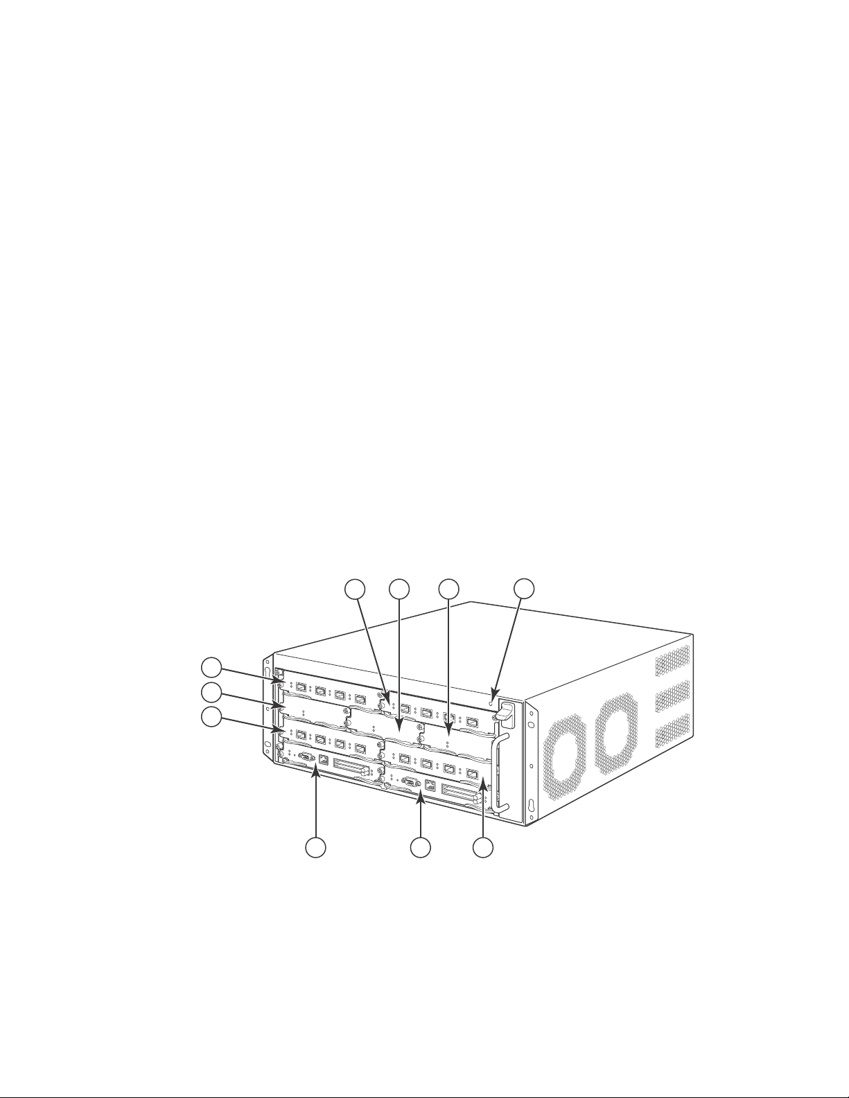
FIGURE 1 BigIron RX-4 chassis
1 Interface slot 2 6 Switch fabric slot 1
2 Switch fabric slot 2 7 Interface slot 3
3 Switch fabric slot 3 8 Management slot 1
4 ESD connector 9 Management slot 2
5 Interface slot 1 10 Interface slot 4
2 Brocade BigIron RX Series Hardware Installation Guide
53-1002483-03
Page 15
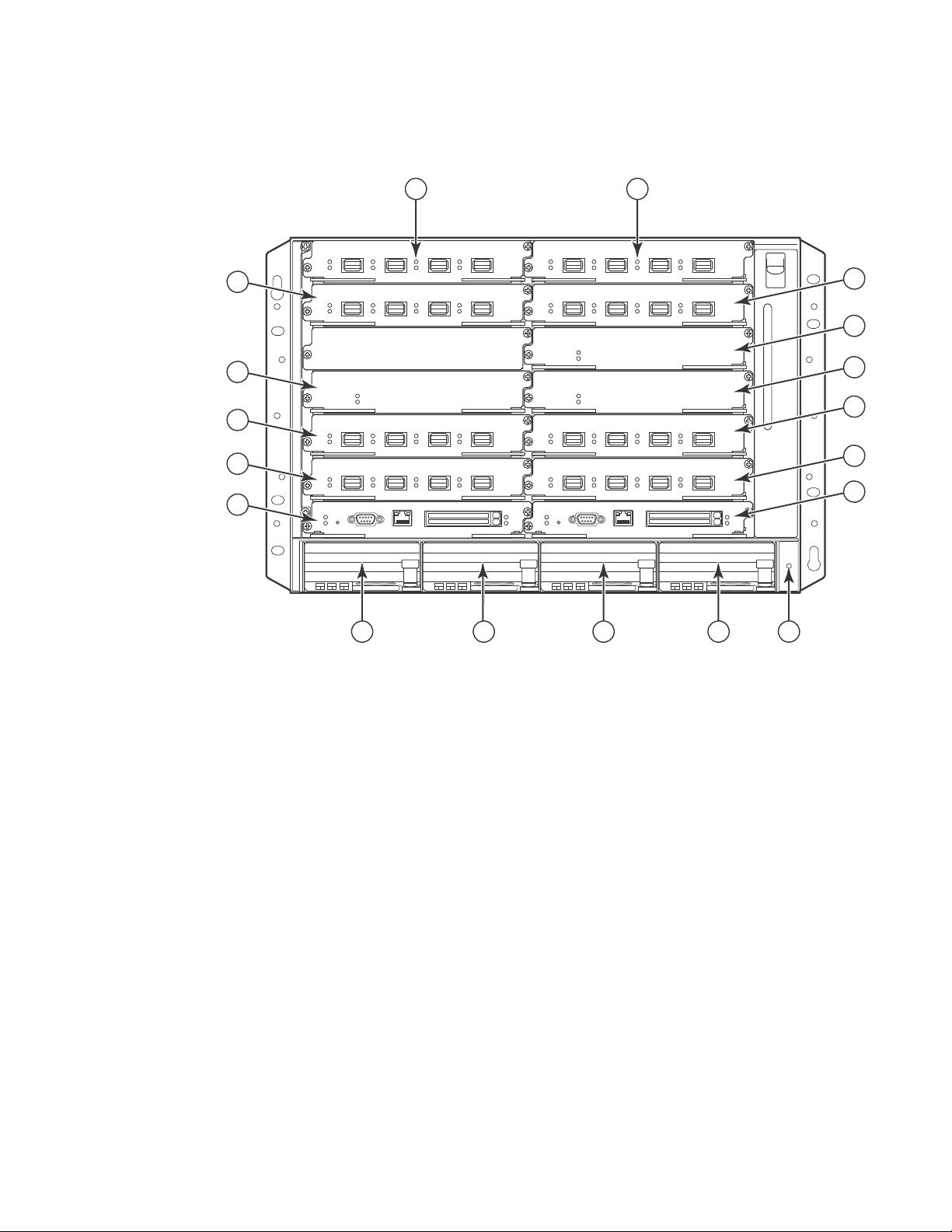
FIGURE 2 BigIron RX-8 chassis
8
10
12
6
9
7
5
4
3
14 15
11
16 17
1 2
13
18
Hardware features
1
1 Interface slot 1 10 Interface slot 7
2 Interface slot 2 11 Interface slot 8
3 Interface slot 3 12 Management slot 1
4 Interface slot 4 13 Management slot 2
5 Switch fabric slot 1 14 Power supply slot 1
6 Switch fabric slot 2 15 Power supply slot 2
7 Switch fabric slot 3 16 Power supply slot 3
8 Interface slot 5 17 Power supply slot 4
9 Interface slot 6 18 ESD connector
Brocade BigIron RX Series Hardware Installation Guide 3
53-1002483-03
Page 16
Hardware features
12
13
14
15
16
17
18
19
20
21
22
23
1
2
3
4
5
6
7
8
91011
1
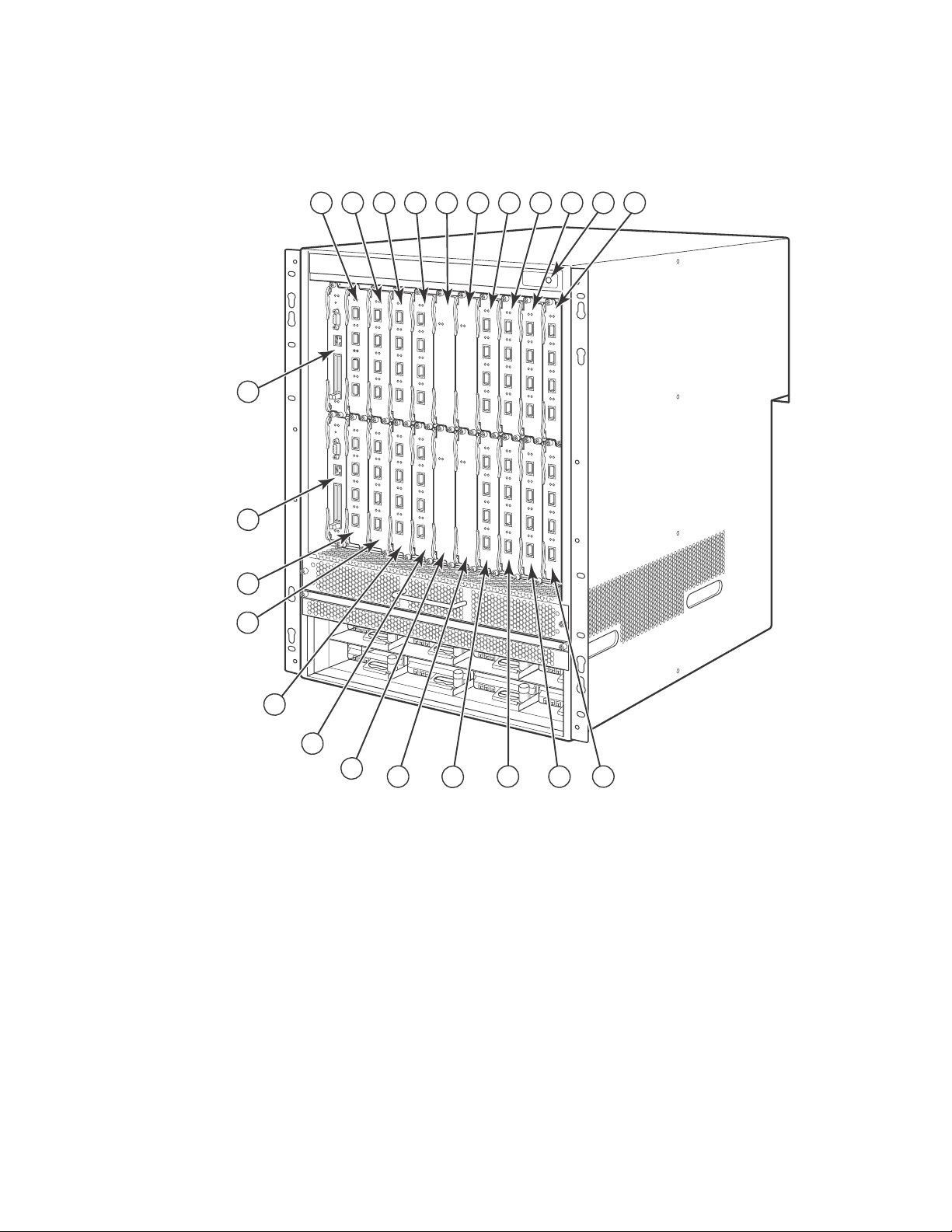
FIGURE 3 BigIron RX-16 chassis
1 Interface slot 1 10 Interface slot 10 19 Switch fabric slot 3
2 Interface slot 2 11 Interface slot 11 20 Switch fabric slot 4
3 Interface slot 3 12 Interface slot 12 21 Management slot 1
4 Interface slot 4 13 Interface slot 13 22 Management slot 2
5 Interface slot 5 14 Interface slot 14 23 ESD connector
6 Interface slot 6 15 Interface slot 15
7 Interface slot 7 16 Interface slot 16
8 Interface slot 8 17 Switch fabric slot 1
9 Interface slot 9 18 Switch fabric slot 2
4 Brocade BigIron RX Series Hardware Installation Guide
53-1002483-03
Page 17

Hardware features
1 Interface slot 1 19 Interface slot 19 37 Switch fabric slot 5
2 Interface slot 2 20 Interface slot 20 38 Switch fabric slot 6
3 Interface slot 3 21 Interface slot 21 39 Switch fabric slot 7
4 Interface slot 4 22 Interface slot 22 40 Switch fabric slot 8
5 Interface slot 5 23 Interface slot 23 41 Management slot 1
6 Interface slot 6 24 Interface slot 24 42 Management slot 2
7 Interface slot 7 25 Interface slot 25 43 Captive screws
8 Interface slot 8 26 Interface slot 26 44 ESD strap connector
9 Interface slot 9 27 Interface slot 27 45 Power supply 1
10 Interface slot 10 28 Interface slot 28 46 Power supply 2
11 Interface slot 11 29 Interface slot 29 47 Power supply 3
12 Interface slot 12 30 Interface slot 30 48 Power supply 4
13 Interface slot 13 31 Interface slot 31 49 Power supply 5
14 Interface slot 14 32 Interface slot 32 50 Power supply 6
15 Interface slot 15 33 Switch fabric slot 1 51 Power supply 7
16 Interface slot 16 34 Switch fabric slot 2 52 Power supply 8
17 Interface slot 17 35 Switch fabric slot 3
18 Interface slot 18 36 Switch fabric slot 4
1
BigIron RX-4
Upon shipment from the factory, the following components are installed in the BigIron RX-4 chassis
as described:
• Two switch fabric modules.
• A slot blank in each interface module slot. The slot blank covers a slot that does not currently
have a module installed in it, ensuring proper airflow within the chassis.
• A fan tray assembly, which is located in the front right side of the chassis. For more information
about the fans, refer to “Cooling system” on page 17.
• One power supply (AC or DC).
In the slots of the chassis you can install the following:
• Up to two management modules (one active and one redundant).
• Up to three switch fabric modules.
• Up to four interface modules.
• Up to three power supplies (AC or DC).
Before installing any modules or power supplies, you must remove the slot blank or blank power
supply faceplate, respectively.
Brocade BigIron RX Series Hardware Installation Guide 5
53-1002483-03
Page 18

Hardware features
CAUTION
1
BigIron RX-8
Upon shipment from the factory, the following components are installed in the BigIron RX-8 chassis
as described:
• Two switch fabric modules.
• A slot blank in each interface module slot. The slot blank covers a slot that does not currently
have a module installed in it, ensuring proper airflow within the chassis.
• A fan tray assembly, which is located in the front right side of the chassis. For more information
about the fans, refer to “Cooling system” on page 17.
• Two power supplies (AC or DC).
In the slots of the chassis you can install the following:
• Up to two management modules (one active and one redundant).
• Up to three switch fabric modules.
• Up to eight interface modules.
• Up to four power supplies (AC or DC).
Before installing any modules or power supplies, you must remove the slot blank or blank power
supply faceplate, respectively.
BigIron RX-16
Upon shipment from the factory, the following components are installed in the BigIron RX-16
chassis as described:
• Three switch fabric modules.
• A slot blank in each interface module slot. The slot blank covers a slot that does not currently
have a module installed in it, ensuring proper airflow within the chassis.
• A fan tray assembly located in the front right side of the chassis. and two fan assemblies
located at the rear of the chassis. For more information about the fans, refer to “Cooling
system” on page 17.
• Four power supplies.
In the slots of the chassis you can install the following:
• Up to two management modules (one active and one redundant).
• Up to four switch fabric modules.
• Up to sixteen interface modules.
• Up to eight power supplies (AC or DC).
Before installing any modules or power supplies, you must remove the slot blank or blank power
supply faceplate, respectively (BigIron RX-4, -8, and 16).
If you do not install a module in a slot, you must keep the slot blank in place. If you run the
chassis with an uncovered slot, the system may overheat.
6 Brocade BigIron RX Series Hardware Installation Guide
53-1002483-03
Page 19
Hardware features
DANGER
NOTE
Pwr
Active
10/100/1000
Port 1
Port 2
Console
RX-BI-MR
1
Figure 1, Figure 2, and Figure 3show the BigIron RX Series chassis and the slots into which you
install the various modules. You must install the primary power supplies and the redundant power
supplies as described in the figures.
Figure 1, Figure 2, and Figure 3 also show an electrostatic discharge (ESD) connector, into which
you can plug an ESD wrist strap to ground yourself while handling and installing modules.
For safety reasons, the ESD wrist strap should contain a 1 meg ohm series resistor.
The BigIron RX-16 chassis versions also include a grounding lug connector, located on the rear
panel (left side). The BigIron RX-4 and BigIron RX-8 have two threaded holes on the right side of the
chassis to accommodate the addition of a ground lug connector.
Management modules
The management module controls the BigIron RX Series hardware components, runs the
networking protocols, and provides the Real Time Operating System (RTOS).
Each BigIron RX Series chassis requires one management module and can accept a second one for
redundancy. A redundant management module works along with the active management module.
If the active module becomes unavailable, the redundant management module automatically
takes over the system operation, minimizing system downtime.
You can install management modules in dedicated slots marked M1 and M2. By default, the
system considers the module installed in the slot marked M1 to be the active management
module.
BigIron RX-4, The BigIron RX Series management module is dedicated, which means that you must
install it in the BigIron RX Series chassis only. If you attempt to install the BigIron RX Series
management module in another Brocade chassis or a management module intended for another
Brocade chassis in the BigIron RX Series chassis, the chassis and module will not function properly..
A management module is hot swappable, which allows you to remove and replace it without
powering down the system.
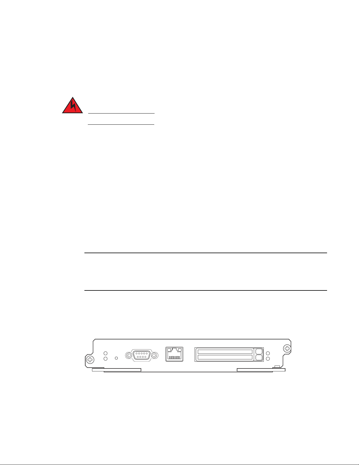
Figure 4 shows the management module’s front panel.
FIGURE 4 Management module front panel
The front panel includes the following control features:
• Two PCMCIA slots
• A Console port
• A 10/100/1000 Ethernet port
• Six LEDs
Brocade BigIron RX Series Hardware Installation Guide 7
53-1002483-03
Page 20

Hardware features
NOTE
1
PCMCIA slots
The PCMCIA slots support a flash PC card. The flash PC card provides storage space in addition to
the system’s flash memory. A flash PC card can store system files, including boot images, startup
configuration files, running configuration files, and so on. As a result, you can perform system
management tasks, such as copying files between flash PC cards, copying files between a flash PC
card and flash memory, and so on.
Console port
The Console port is a standard DB-9 serial connector through which you can attach a PC or
terminal to configure the BigIron RX Series system using the command line interface (CLI).
This port interfaces the control plane only and not the data plane.
10/100/1000 Ethernet port
The front panel includes a 10BaseT/100BaseTX/1000BaseTX auto-sensing, auto-negotiating
Ethernet port. This port has an RJ-45 unshielded twisted pair (UTP) connector.
Typical uses of this port include but are not limited to the following:
• Connecting a PC through which you can access the system through a Telnet or SSHv2
connection and configure, monitor, and manage the BigIron RX Series system.
• Connecting to the 10BaseT/100BaseTX/1000BaseTX port of a switch or router, for
connectivity to your existing management network. You can then access the BigIron RX Series
system and configure, monitor, and manage the system from a management station.
The existing management network into which you can connect the 10/100/1000 Ethernet port
must be separate and isolated from the network over which user packets are switched and routed.
This port interfaces the control plane only and not the data plane.
LEDs
Tab le 1 describes the LEDs on the management module’s front panel.
TABLE 1 Management module LEDs
LED Position State Meaning
Port 1
and
Port 2
Active Lower Left On The module is functioning as the active management
Pwr Upper Left On The module is receiving power.
Each adjacent to
the PCMCIA slot
that is
represents
On or blinking You have inserted a PCMCIA flash card in a slot or initiated
a task related to the file management system on a flash
card. As a result, the software is currently accessing the
flash card.
Off The software is not currently accessing a PCMCIA flash card
inserted in a slot.
module.
Off The module is functioning as the redundant management
module.
Off The module is not receiving power.
8 Brocade BigIron RX Series Hardware Installation Guide
53-1002483-03
Page 21
NOTE
TABLE 1 Management module LEDs (Continued)
LED Position State Meaning
Hardware features
1
10/100/100
0 Ethernet
Port
10/100/100
0 Ethernet
Port
Above and right
of RJ-45
connector
Above and left of
RJ-45 connector
On (Green) A link is established with the remote port.
Off A link is not established with the remote port.
On or blinking
(Yellow)
Off for an
extended period
The port is transmitting and receiving packets.
The port is not transmitting or receiving packets.
Interface modules
You can install up to 16 BigIron RX Series interface modules in the BigIron RX Series chassis as
described:
• BigIron RX-4: Supports up to 4 interface modules
• BigIron RX-8: Supports up to 8 interface modules
• BigIron RX-16: Supports up to 16 interface modules
A BigIron RX Series interface module is dedicated, which means that you must install it in the BigIron
RX Series chassis only. If you attempt to install a BigIron RX Series interface module in another
Brocade chassis or an interface module intended for another Brocade chassis in the BigIron RX
Series chassis, the module will not boot up to become active. Interface modules can be shared
between BigIron RX-4, BigIron RX-8, and BigIron RX-16.
The interface modules are hot swappable, which means you can remove and replace them without
powering down the system.
4-port 10 Gigabit Ethernet module
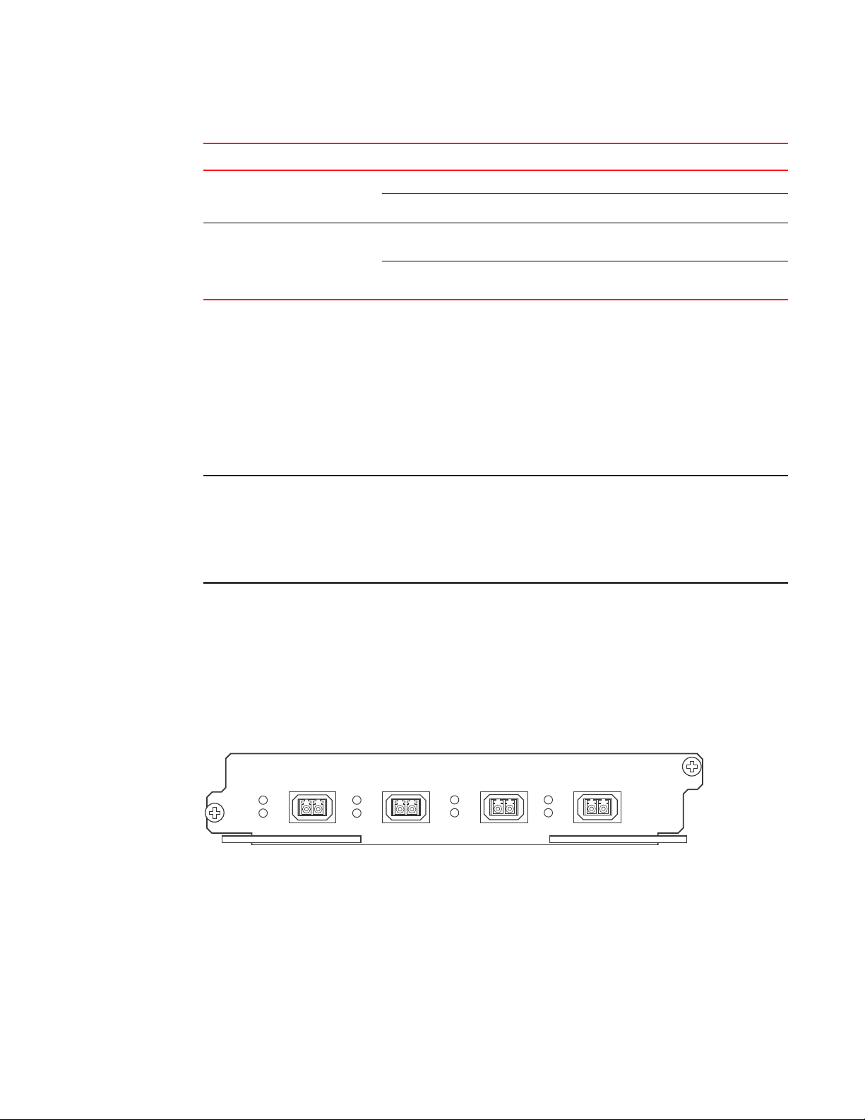
Figure 5 shows the 4-port 10 Gigabit Ethernet module’s front panel with XFP modules installed.
FIGURE 5 4-port 10 Gigabit Ethernet module front panel
The front panel includes the following control features:
• Four LEDs
• Four 10 Gigabit Ethernet XFP slots
LEDs
The module’s front panel includes two LEDs that indicate the status of each port.
Tab le 2 describes the LEDs on the 10 Gigabit Ethernet module’s front panel.
Brocade BigIron RX Series Hardware Installation Guide 9
53-1002483-03
Page 22

Hardware features
1
TABLE 2 10 Gigabit Ethernet module LEDs
LED Position State Meaning
Link Left of each
Ethernet port
Active Left of each
Ethernet port
On A link is established with the remote port.
Off A link is not established with the remote port.
On or blinking The port is transmitting and receiving packets.
Off for an extended
period
The port is not transmitting or receiving
packets.
A two 10-Gigabit Ethernet module contains two physical ports, through which you can connect your
BigIron RX Series switch to other network devices at a speed of 10 Gigabits.
Into a physical port, you must insert a fiber-optic module provided by Brocade. The XFP-compliant
fiber-optic modules provide an optical transceiver or physical medium dependent (PMD) interface
for single mode fiber that can be used with the LAN physical layer (PHY).
The following optic modules versions are available from Brocade:
• Short wavelength (86 – 300 meters) – Brocade part number 10G-XFP-SR
• Long wavelength (10 kilometers) – Brocade part number 10G-XFP-LR
• Extra long wavelength (40 kilometers) – Brocade part number 10G-XFP-E=The front panel
includes the following control features:
• Eight LEDs
• Four 10 Gigabit Ethernet XFP slots
LEDs
The module’s front panel includes two LEDs that indicate the status of each port.
Tab le 3 describes the LEDs on the 10 Gigabit Ethernet module’s front panel.
TABLE 3 10 Gigabit Ethernet module LEDs
LED Position State Meaning
Link Left of each
Ethernet port
Active Left of each
Ethernet port
On A link is established with the remote port.
Off A link is not established with the remote port.
On or blinking The port is transmitting and receiving packets.
Off for an extended
period
The port is not transmitting or receiving
packets.
10 Gigabit Ethernet ports
A 10 Gigabit Ethernet module contain four physical ports, through which you can connect your
BigIron RX Series switch to other network devices at a speed of 10 Gigabits.
Into a physical port, you must insert a fiber optic module provided by Brocade. The XFP-compliant
fiber optic modules provide an optical transceiver or physical medium dependent (PMD) interface
for single mode fiber that can be used with the LAN physical layer (PHY).
10 Brocade BigIron RX Series Hardware Installation Guide
53-1002483-03
Page 23
Hardware features
The following optic modules versions are available from Brocade:
1
• Short wavelength (86 – 300 meters) – Brocade part number 10G-XFP-SR
• Long wavelength (10 kilometers) – Brocade part number 10G-XFP-LR
• Extra long wavelength (40 kilometers) – Brocade part number 10G-XFP-ER
16-port 10 Gigabit Ethernet oversubscribed module
The 16 x 10GE oversubscribed module for the BigIron RX plugs into any port slot of the switch and
is compatible with all previous generations of card on that switch. It provides interfaces to 16 X
10GE ports.
Figure 6 shows the 16-port 10 Gigabit Ethernet module’s front panel.
FIGURE 6 16-port 10 Gigabit Ethernet module front panel
The front panel includes the following control features:
• 16 LEDs
• 16 x 10 Gigabit Ethernet XFP slots
LEDs
The module’s front panel includes 16 LEDs that indicate the status of each port.
Tab le 4 describes the LEDs on the 10 Gigabit Ethernet module’s front panel.
TABLE 4 10 Gigabit Ethernet module LEDs
LED Position State Meaning
Link Below each
Ethernet port
Active Below each
Ethernet port
The following optic modules versions are available from Brocade:
On A link is established with the remote port.
Off A link is not established with the remote port.
On or blinking The port is transmitting and receiving packets.
Off for an extended period The port is not transmitting or receiving
packets.
• Short wavelength (86 – 300 meters) – Brocade part number 10G-XFP-SR
• Long wavelength (10 kilometers) – Brocade part number 10G-XFP-LR
• Extra long wavelength (40 kilometers) – Brocade part number 10G-XFP-E=The front panel
includes the following control features:
• 16 LEDs
• 16 x 10 Gigabit Ethernet XFP slots.
Brocade BigIron RX Series Hardware Installation Guide 11
53-1002483-03
Page 24

Hardware features
NOTE
NOTE
1
High speed fans requirements
• TheBigIron RX 16 requires upgrading of the rear fan modules to NI-X-16-FAN-EXH-A modules. If
the BigIron RX switch is not upgraded to support NI-X-16-FAN-EXH-A modules when 16x10G
modules are in the BigIron RX system, then the syslog message such as the following will be
displayed: SYSLOG: Mar 26 14:19:53:<12>R1, 16x10G modules in slots 10,11,13,16 must
not be running without high speed fans.
NI-X-16-FAN-EXH-A module is not shipped by default with the BigIron RX Switch. Please contact
Brocade for purchasing this module.
• When installing 16x10G modules in the BigIron RX Switch, the operating temperature must not
exceed 30C.
To display NI-X-16-FAN-EXH-A modules in an BigIron RX Switch, enter the show chassis command.
The show chassis command displays firmware Revision A (Rev A) for NI-X-16-FAN-EXH-A modules.
Rev A indicates that the BigIron RX Switch contains the required rear fan modules to support the
16X10G modules. The rpm value threshold’s (LOW/MED/MED-HI/HI) are also displayed for rear fan
modules.
If the BigIron RX Switch does not contain NI-X-16-FAN-EXH-A modules, the show chassis command
will not display Rev A for rear fan modules.
Hardware limitations
• Mirror (analyzer) ports cannot be assigned to the 16x10 card. You can monitor traffic on
16x10 ports.
• Brocade currently only supports "strict" and "destination-weighted" scheduling schemes (qos
scheduler). Refer to the Configuring QoS chapter in the BigIron RX Series Configuration Guide
for more informaton.
10 Gigabit Ethernet ports
A 16 x 10 Gigabit Ethernet module contain 16 physical ports, through which you can connect the
BigIron RX Series switch to other network devices at a speed of 10 Gigabits.
You must insert a fiber optic module provided by Brocade into a physical port. The XFP-compliant
fiber optic modules provide an optical transceiver or physical medium dependent (PMD) interface
for single mode fiber that can be used with the LAN physical layer (PHY).
The following optic modules versions are available from Brocade:
• Short wavelength (86 – 300 meters) – Brocade part number 10G-XFP-SR
• Long wavelength (10 kilometers) – Brocade part number 10G-XFP-LR
• Extra long wavelength (40 kilometers) – Brocade part number 10G-XFP-ER
Gigabit Ethernet interface module (SFP)
The 24-port 1 Gigabit Ethernet mini-GBIC (or SFP) is auto-sensing, auto-negotiating Ethernet port
and will select the FE or GE mode of operation based on the link signal received.
12 Brocade BigIron RX Series Hardware Installation Guide
53-1002483-03
Page 25
Hardware features
NOTE
NOTE
1
The device will be FE or GE capable, but will only display that is GE to indicate the maximum speed
capability of the module.
The actual speed will be displayed once the link is seen and the port auto-senses the speed of the
SFP.
You can issue the show media command to display the type of optic installed and determine the
speed the port will run at when the link is received.
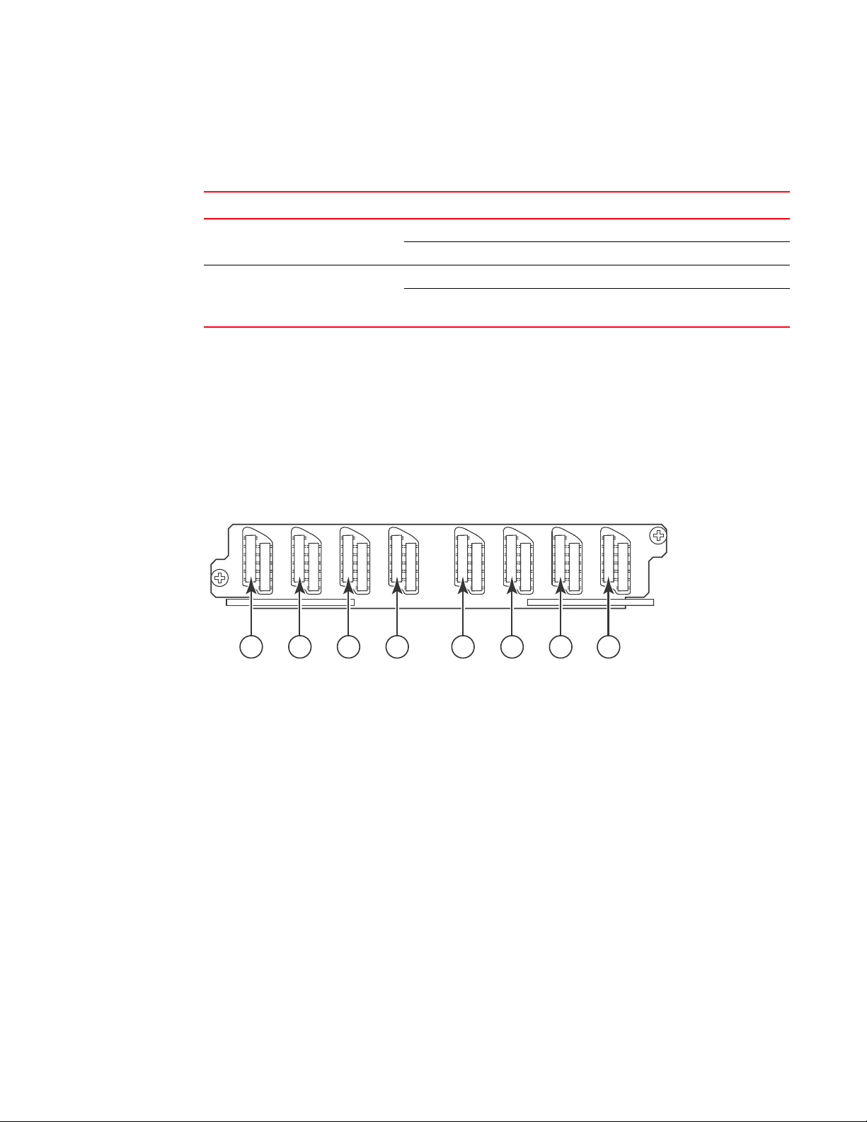
Figure 7 shows the 24-port 1 Gigabit Ethernet mini-GBIC (or SFP) module’s front panel.
1
FIGURE 7 24-port 1 Gigabit Ethernet SFP module front panel
1Port status LEDs
The front panel includes the following control features:
• LEDs
• 24 1-Gigabit Ethernet mini-GBIC (SFP) ports
TABLE 5 Gigabit Ethernet module LEDs
Position State Meaning
Below each Ethernet
port
(left-side LED
supports port in top
row while right-side
LED supports port in
bottom row)
On or blinking The port is transmitting and receiving packets.
Off for an extended period The port is not transmitting or receiving packets.
Gigabit Ethernet interface module (RJ-45)
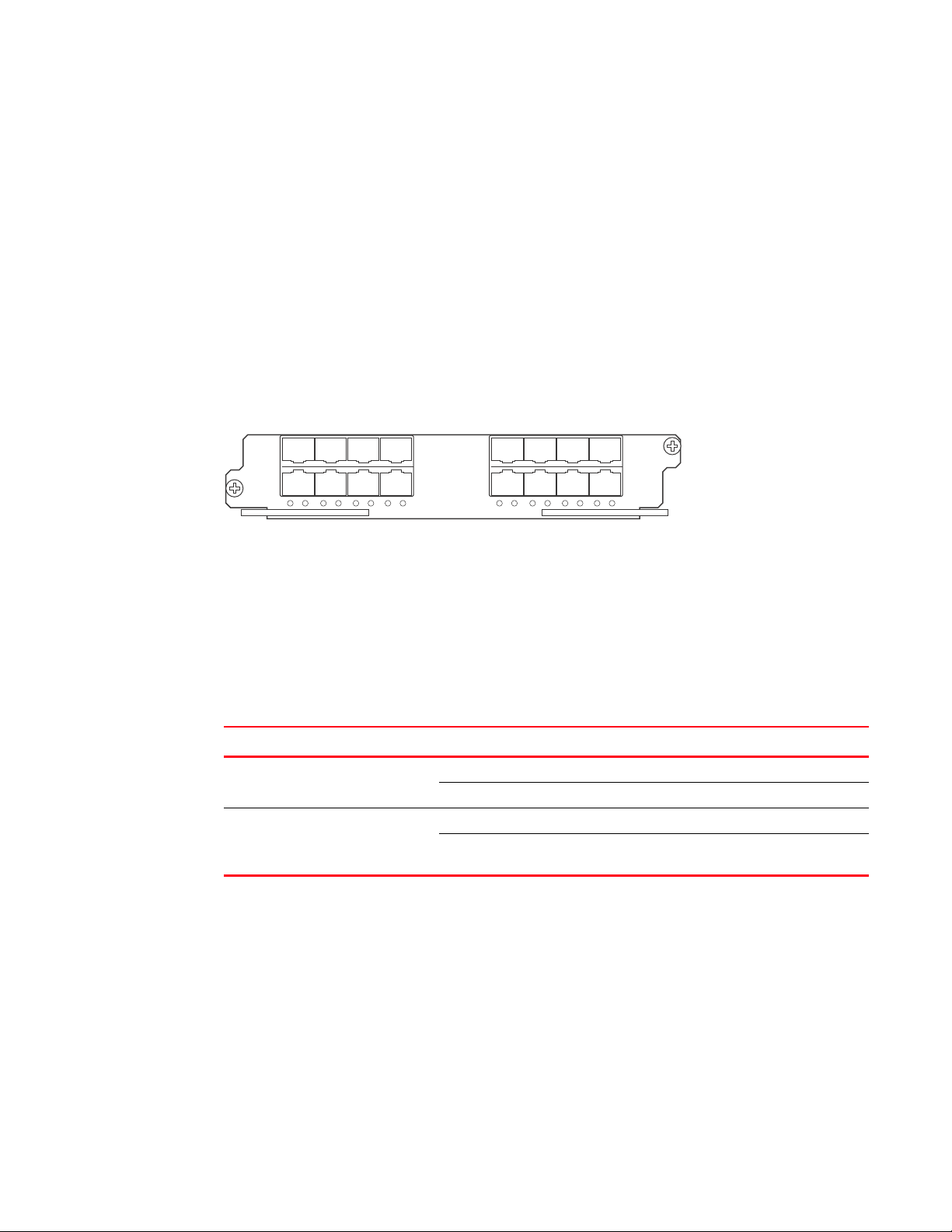
Figure 8 shows the 24-port 1 Gigabit Ethernet module’s front panel.
FIGURE 8 24-port 1 Gigabit Ethernet module front panel
The front panel includes the following control features:
Brocade BigIron RX Series Hardware Installation Guide 13
53-1002483-03
Page 26
Hardware features
1
6
7
12
13
18
19
24
25
30
31
36
37
42
43
48
1 2 3 4 5 6 7 8
1
• LEDs
• 24 1-Gigabit Ethernet ports
TABLE 6 Gigabit Ethernet module LEDs
LED Position State Meaning
Link Left of each
Ethernet port
Active Left of each
Ethernet port
On A link is established with the remote port.
Off A link is not established with the remote port.
On or blinking The port is transmitting and receiving packets.
Off for an extended
period
The port is not transmitting or receiving
packets.
48-port 1 Gigabit Ethernet interface module (Mini RJ 21 Copper)
The interface modules are hot swappable, which means you can remove and replace them without
powering down the system.
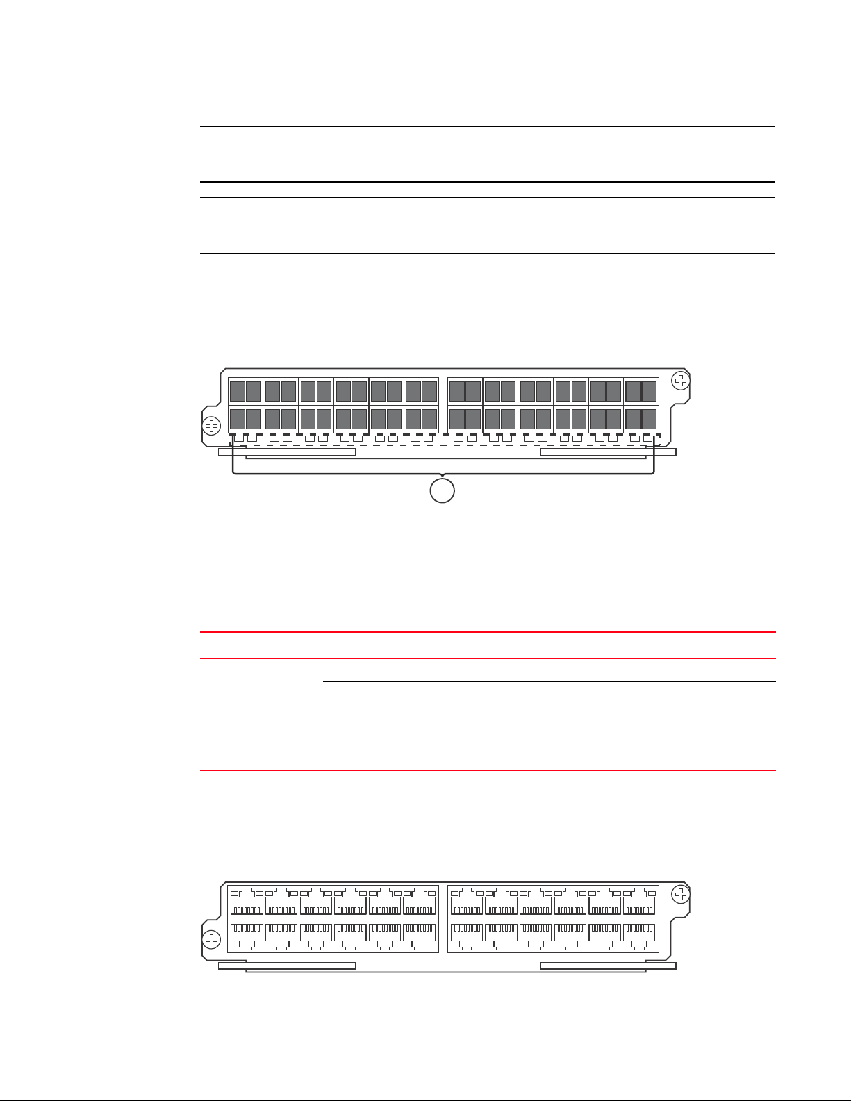
Figure 9 shows the 48-port GoC interface module’s front panel.
FIGURE 9 48-port GoC interface module front panel
1 Ports 1 -6 5 Ports 25-30
2 Ports 7-12 6 Ports 31-36
3 Ports 13 -18 7 Ports 37-42
4 Ports 19 -24 8 Ports 43-48
The front panel includes eight Mini RJ-21 Connectors that support six 10/100/1000 Gigabit
Ethernet ports each. Figure 9 shows the ports that are supported per RJ-21 connector. A cable
connects from the RJ-21 connector on the interface module to a Mini RJ-21 connector on a patch
panel. At the patch panel, the ports are broken out into individual RJ-45 connectors for each port.
Cables and patch panels that support this module are available through any Tyco International
distribution partner. Information about these products is available at the following URL:
www.ampnetconnect.com/foundrynetworks
14 Brocade BigIron RX Series Hardware Installation Guide
53-1002483-03
Page 27

Hardware features
NOTE
NOTE
NOTE
High speed fans requirements
1
• TheBigIron RX 16 requires upgrading of the rear fan modules to NI-X-16-FAN-EXH-A modules. If
the BigIron RX switch is not upgraded to support NI-X-16-FAN-EXH-A modules when 48x1G
modules are in the BigIron RX system, then the syslog message such as the following will be
displayed: SYSLOG: Mar 26 14:19:53:<12>R1, 48x1G modules in slots 10,11,13,16 must not
be running without high speed fans.
NI-X-16-FAN-EXH-A module is not shipped by default with the BigIron RX Switch. Please contact
Brocade for purchasing this module.
• When installing 48x1G modules in the BigIron RX Switch, the operating temperature must not
exceed 30C.
To display NI-X-16-FAN-EXH-A modules in an BigIron RX Switch, enter the show chassis command.
The show chassis command displays firmware Revision A (Rev A) for NI-X-16-FAN-EXH-A modules.
Rev A indicates that the BigIron RX Switch contains the required rear fan modules to support the
48x1G modules. The rpm value threshold’s (LOW/MED/MED-HI/HI) are also displayed for rear fan
modules.
If the BigIron RX Switch does not contain NI-X-16-FAN-EXH-A modules, the show chassis command
will not display Rev A for rear fan modules.
Switch fabric module
The switch fabric module switches uses packets from one interface module installed in a chassis to
another. The BigIron RX Series switches can be configured with switch fabric modules as
described:
• BigIron RX-4: Accommodates three switch fabric elements with two required and one
redundant for a fully loaded system. It is shipped with two switch fabric elements. You must
purchase an additional switch fabric element if you want your BigIron RX-4 equipped for
redundancy.
• BigIron RX-8: Accommodates three switch fabric elements with two required and one
redundant for a fully loaded system. It is shipped with two switch fabric elements. You must
purchase an additional switch fabric element if you want your BigIron RX-8 equipped for
redundancy.
• BigIron RX-16: Accommodates four switch fabric elements with three required and one
redundant for a fully loaded system. It is shipped with three switch fabric elements. You must
purchase an additional switch fabric element if you want your BigIron RX-16 equipped for
redundancy.
The switch fabric elements used for the BigIron RX-4 are a different part than those used on the
BigIron RX-8, and BigIron RX-16.
The BigIron RX Series switch fabric module is dedicated, which means that it functions properly in
the BigIron RX Series chassis only. If you attempt to install a BigIron RX Series switch fabric module
in another Brocade chassis or a switch fabric module intended for another Brocade chassis in the
BigIron RX Series chassis, the chassis and switch fabric module will not function properly.
Brocade BigIron RX Series Hardware Installation Guide 15
53-1002483-03
Page 28

Hardware features
Pwr
Active
BI-SWF
1
Figure 10 shows the switch fabric module’s front panel.
FIGURE 10 Switch fabric module front panel
The front panel includes two LEDs, which Tab le 7 describes.
TABLE 7 Switch fabric module LEDs
LED Position State Meaning
Pwr Above Active LED On The module is receiving power.
Off The module is not receiving power.
Active Below Pwr LED On The chassis switch fabric is active and ready
to switch user packets.
Off for an extended
period
The chassis switch fabric is not active and
cannot switch user packets.
Power supplies
The BigIron RX Series switches support the following power supply options:
• BigIron RX-4: Accommodates three power supplies (AC or DC) with one required and two
redundant. It is shipped with one power supply. You must purchase one or two additional
power supplies if you want your BigIron RX-4 equipped for redundancy.
• BigIron RX-8: Accommodates four power supplies (AC or DC) with two required and two
redundant. Because power is supplied over a common power bus, any power supply purchased
in addition to the two required will provide backup for any supply that fails. Equipping a BigIron
RX-8 with two additional power supplies provides full redundancy for both of the required
power supplies.
• BigIron RX-16: Accommodates eight power supplies (AC or DC) with four required and four
redundant. Because power is supplied over a common power bus, any power supply purchased
in addition to the four required will provide backup for any supply that fails. Equipping a BigIron
RX-16 with four additional power supplies provides full redundancy for all of the required power
supplies.
In the BigIron RX-8, and BigIron RX-16, you install the power supplies (AC or DC) in the slots along
the bottom of the chassis. In the BigIron RX-4, the power supplies (AC or DC) are installed in slots in
the rear of the chassis.The installed power supplies provide power to all chassis components,
sharing the workload equally and reporting their status to the management module. If the
management module detects that one of these power supplies has failed or overheated, the
management module will redistribute the failed power supply’s workload to the remaining power
supplies.
16 Brocade BigIron RX Series Hardware Installation Guide
53-1002483-03
Page 29
Hardware features
DANGER
NOTE
1
Each power supply has three LEDs on its faceplate that provide status for the input power, output
power and notification of alarms sent. If the input power and output power LEDs are on (a steady
green), the power supply is providing power to the chassis components. The power supplies are hot
swappable, which means you can remove and replace them without powering down the system.
The power supplies are hot swappable, which means they can be removed and replaced while
the BigIron RX Series chassis is powered on and running. However, Brocade recommends that
you disconnect a power supply from its power source before removing and replacing it. The
BigIron RX-8, or -16 chassis can be running while a power supply is being removed and replaced,
but the power supply itself should not be connected to a power source. Otherwise, you could be
injured or the power supply or other parts of the device could be damaged. (
1
Cooling system
The cooling system of BigIron RX Series switches is configured as described:
• BigIron RX-4: Is equipped with a fan module containing two 4-speed fans.
• BigIron RX-8: Is equipped with a fan module containing four 4-speed fans.
• BigIron RX-16: Is equipped with three fan assemblies. The fan tray located in the lower front of
the chassis contains six 4-speed fans. There are two fan assemblies located in the rear of the
chassis. Each of these contain a 4-speed fan that pulls air through the chassis. The BigIron
RX-16 is equipped with eight controllers to support redundancy.
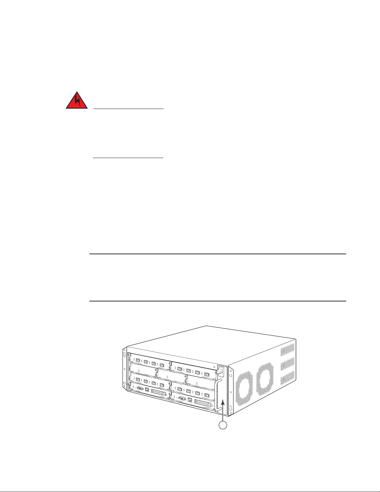
As shown in Figure 11 and Figure 12, the fans are located in the front of the BigIron RX-4 and BigIron
RX-8 chassis. Figure 13 and Figure 14 show the front and rear locations of the fans on the BigIron
RX-16. A new revision of the controller for the fan tray assemblies has been added for software
release 02.2.01 and later. There is no visible change to the fan assemblies or the procedures for
replacing the assemblies. Earlier software versions will not recognize the new controller.
FIGURE 11 Fan component locations for the BigIron RX-4
1Fan module
Brocade BigIron RX Series Hardware Installation Guide 17
53-1002483-03
Page 30
Hardware features
1
1
1
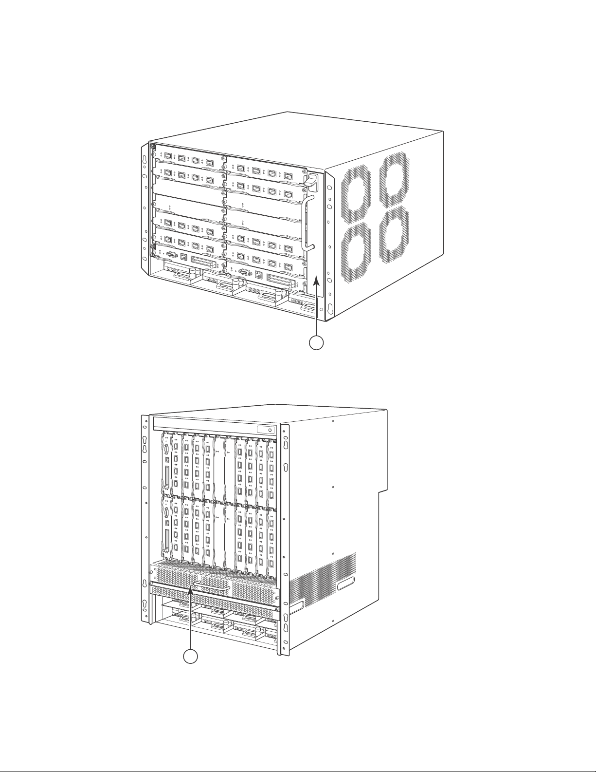
FIGURE 12 Fan component locations for the BigIron RX-8
1Fan module
FIGURE 13 Front fan component locations for the BigIron RX-16
1 Front fan assembly
18 Brocade BigIron RX Series Hardware Installation Guide
53-1002483-03
Page 31

FIGURE 14 Rear fan component locations for the BigIron RX-16
1
Hardware features
1
1Fan modules
Upon system startup, the fans in the BigIron RX Series switches operate at high speed, then the
management module lowers the fan speed to low speed.
By default, the BigIron RX Series switch polls the temperature sensor on each module every 60
seconds to get a temperature reading. Depending on the temperature readings for the modules,
the system can do the following:
• Leave the fan speed as is
• Increase the fan speed
• Decrease the fan speed
• Shut down a module to prevent damage
If the temperature of a module exceeds specified high temperature thresholds, the system
generates a Syslog message and SNMP trap. The system can also shut the module down if the
temperature exceeds the highest threshold.
LEDs
The fan control modules include a bi-color LED, which indicates the status of the fans. Table 8
describes the LED.
Brocade BigIron RX Series Hardware Installation Guide 19
53-1002483-03
Page 32

Supported software features
CAUTION
1
TABLE 8 Fan control module LED
LED Position State Meaning
Fan control module
LED
To avoid overheating of the BigIron RX Series chassis, do not remove more than one fan at a time.
Rear of chassis Off The fans are not receiving power.
Green The fans are working and responding to
controls from the fan control module.
Amber The fans are not working and not responding
to controls from the fan control module.
Rack mount kit
The BigIron RX Series switches are shipped equipped for mounting in a standard 19-inch
(EIA310-D) rack as described:
• The BigIron RX-4 and BigIron RX-8 are equipped with built-in mounting brackets and are
shipped with mounting screws.
• The BigIron RX-16 switches ship with two L-shaped mounting brackets and mounting screws.
Alternatively, you can use a mid-mount kit (ordered separately) to center-mount the BigIron RX
chassis using two L-shaped mounting brackets. The mid-mount kit comes with instructions for
installing the mounting brackets and mounting the device in a rack.
Contact Brocade Communications Systems, Inc for information about mid-mount kits.
In a rack, you can install the following number of BigIron RX Series chassis depending on the
model:
• BigIron RX-16 – up to 3 BigIron RX-16 chassis
• BigIron RX-8 – up to 6 BigIron RX-8 chassis
• BigIron RX-4 – up to 10 BigIron RX-4 chassis
Supported software features
For a complete list of software features supported on the BigIron RX Series switch, refer to the
software release notes for this device. For information about configuring basic, non-protocol
software features supported on this device,refer to the BigIron RX Series Configuration Guide.
20 Brocade BigIron RX Series Hardware Installation Guide
53-1002483-03
Page 33

Chapter
DANGER
DANGER
DANGER
Installing the BigIron RX Series Switch
In this chapter
•Installation precautions . . . . . . . . . . . . . . . . . . . . . . . . . . . . . . . . . . . . . . . . . 21
•Installing a BigIron RX-4 switch . . . . . . . . . . . . . . . . . . . . . . . . . . . . . . . . . . . 24
•Installing a BigIron RX-16 switch . . . . . . . . . . . . . . . . . . . . . . . . . . . . . . . . . . 43
•Attaching a management station . . . . . . . . . . . . . . . . . . . . . . . . . . . . . . . . . . 54
•Powering-on the power source . . . . . . . . . . . . . . . . . . . . . . . . . . . . . . . . . . . . 55
•Verifying proper operation. . . . . . . . . . . . . . . . . . . . . . . . . . . . . . . . . . . . . . . . 56
Installation precautions
This chapter contains information on how to install a BigIron RX Series switch. Before proceeding,
please read the cautions and warnings below that apply to the entire family of BigIron RX Series
switches.
2
The procedures in this manual are for qualified service personnel.
If the installation requires a different power cord than the one supplied with the device, make
sure you use a power cord displaying the mark of the safety agency that defines the regulations
for power cords in your country. The mark is your assurance that the power cord can be used
safely with the device.
Follow these precautions when installing a BigIron RX Series switch.
General precautions
All fiber-optic interfaces use Class 1 Lasers.
Brocade BigIron RX Series Hardware Installation Guide 21
53-1002483-03
Page 34

Installation precautions
CAUTION
CAUTION
CAUTION
CAUTION
CAUTION
DANGER
DANGER
DANGER
2
Do not install the device in an environment where the operating ambient temperature might
exceed 40o C (104o F).
Make sure the air flow around the front, sides, and back of the device is not restricted.
If you do not install a module in a slot, you must keep the slot blank in place. If you run the
chassis with an uncovered slot, the system may overheat.
Never leave tools inside the chassis.
Power precautions
Use a separate branch circuit for each AC power cord, which provides redundancy in case one of
the circuits fails.
Make sure to choose the appropriate circuit device, depending on the number of AC power
supplies installed in the chassis.
Disconnect the power cord from all power sources to completely remove power from the device.
Make sure that the power source circuits are properly grounded, then use the power cord
supplied with the device to connect it to the power source.
22 Brocade BigIron RX Series Hardware Installation Guide
53-1002483-03
Page 35

Installation precautions
DANGER
DANGER
DANGER
CAUTION
CAUTION
CAUTION
If the installation requires a different power cord than the one supplied with the device, make
sure you use a power cord displaying the mark of the safety agency that defines the regulations
for power cords in your country. The mark is your assurance that the power cord can be used
safely with the device.
Make sure the rack or cabinet housing the device is adequately secured to prevent it from
becoming unstable or falling over.
Mount the devices you install in a rack or cabinet as low as possible. Place the heaviest device at
the bottom and progressively place lighter devices above.
2
Ensure that the device does not overload the power circuits, wiring, and over-current protection.
To determine the possibility of overloading the supply circuits, add the ampere (amp) ratings of all
devices installed on the same circuit as the device. Compare this total with the rating limit for the
circuit. The maximum ampere ratings are usually printed on the devices near the input power
connectors.
BigIron RX-4, -8, and -16 devices with DC power sources are intended for installation in restricted
access areas only. A restricted access area is where access can be gained only by service
personnel through the use of a special tool, lock and key, or other means of security, and is
controlled by the authority responsible for the location.
For a DC system, the gauge of wire will be determined by the power source as well as the power
supply draw (refer to Table 9). Use a grounding wire of at least 6 American Wire Gauge (AWG). The
AWG wire should be attached to an agency-approved crimp connector (provided on the BigIron RX
Series chassis), crimped with the proper tool. The single crimp connector should allow for
securement to both ground screws on the enclosure. For BigIron RX-16, and -8, and -4, use a
grounding wire of at least 6 AWG. For the grounding lug, use UL-listed Panduit crimp connector,
P/N LCD6-10A, and two 10-32, PPH screws to secure the crimp connector to chassis. The
grounding position is located on the side of chassis, adjacent ground symbol.
Brocade BigIron RX Series Hardware Installation Guide 23
53-1002483-03
Page 36

Installing a BigIron RX-4 switch
CAUTION
2
TABLE 9 The American Wire Gauge (AWG) guidelines
AWG Ohms per 100 feet Maximum Amps for chassis wiring Maximum Amps for power
5 0.3133 118 47
6 0.3951 101 37
7 0.4982 89 30
8 0.6282 73 24
9 0.7921 64 19
10 0.9989 55 15
11 1.26 47 12
12 1.588 41 9.3
For the DC input circuit to the system, make sure there is a UL-Listed 30 amp circuit breaker,
minimum -48Vdc, double pole, on the input to the terminal block. The input wiring for connection
to the product should be Listed copper wire, 8 AWG, marked VW-1, and rated minimum 9o C.
transmission
Installing a BigIron RX-4 switch
This section describes the steps you will perform to install a BigIron RX-4 switch:
• “Preparing the installation site”
• “Unpacking a BigIron RX-4 switch”
• “Chassis lifting guidelines for BigIron RX-4 switches”
• “Installing a BigIron RX-4 chassis in a rack”
• “Installing BigIron RX-4 modules”
• “Installing power supplies in a BigIron RX-4 chassis”
• “Connecting AC power to a BigIron RX-4 chassis”
• “Connecting DC power to a BigIron RX-4 chassis”
• “Final steps”
Preparing the installation site
Cabling infrastructure
Ensure that the proper cabling is installed in the site.
For information on cabling, refer to “Installing power supplies in a BigIron RX-4 chassis” on
page 30, “Attaching a management station” on page 54, and “Connecting a BigIron RX Series
switch” on page 71.
24 Brocade BigIron RX Series Hardware Installation Guide
53-1002483-03
Page 37

Installing a BigIron RX-4 switch
NOTE
DANGER
2
Installation location
Before installing the switch, plan its location and orientation relative to other devices and
equipment. For cooling purposes, allow a minimum of six inches of space between the sides, front,
and the back of the chassis and walls or other obstructions. If a chassis is installed within a
perforated enclosure, the perforations must have openings on at least 60 percent of the surface.
Unpacking a BigIron RX-4 switch
The BigIron RX-4 switch ships with several items. Review the list below, and verify the contents. If
any items are missing, contact the place of purchase:
• BigIron RX-4 chassis with the appropriate number of switch fabric modules already installed in
the slot marked SF and slot blanks installed in all other module slots.
You must provide standard #12-24 pan-head screws for mounting the BigIron RX-4 chassis into a
rack.
• A 115V AC power cable for each AC power supply you purchase from Brocade.
Follow the steps given below to unpack a BigIron RX-4 chassis.
1. Move the pallet to a staging area as close to the installation site as possible.
2. Position the shipping carton with the arrows pointing up.
3. Remove the strap that secures the shipping carton to the pallet.
4. Remove the plastic cover and shipping carton.
5. Save the shipping carton, pallet, and packing materials in case you need to move or ship the
chassis at a later time.
Chassis lifting guidelines for BigIron RX-4 switches
A fully-populated BigIron RX-4, chassis is heavy. TWO OR MORE PEOPLE ARE REQUIRED WHEN
LIFTING, HANDLING, OR MOUNTING THESE DEVICES.
Before lifting or moving the switch, disconnect all external cables. For lifting and moving a BigIron
RX-4 chassis, follow the guidelines explained in this section.
Installing a BigIron RX-4 chassis in a rack
This section describes the following tasks:
• “Preparing to mount a BigIron RX-4 chassis in a rack”
• “Removing BigIron RX-4 extra shipment screws”
• “Mounting a BigIron RX-4 chassis in a rack”
• “Removing the slot blanks”
Brocade BigIron RX Series Hardware Installation Guide 25
53-1002483-03
Page 38

Installing a BigIron RX-4 switch
3
1
2
2
Preparing to mount a BigIron RX-4 chassis in a rack
Because of the weight of a fully loaded BigIron RX-4 chassis, Brocade recommends mounting a
chassis in a rack before installing the modules and AC power supplies if necessary.
In a standard 19-inch (EIA310-D) rack, you can install up to ten BigIron RX-4 chassis.
For each BigIron RX-4 chassis that you install in a rack, you must provide four standard #12-24
pan-head screws with which to mount and secure the chassis. Before performing this task, you
should have an assembled rack and a #2 Phillips-head screwdriver.
Removing BigIron RX-4 extra shipment screws
The BigIron RX-4 ships with two extra screws installed in the right side of the chassis. These screws
secure the fan tray, protecting it from damage during shipment. You must remove these screws
before installing the chassis. Figure 15 shows the location of the screws.
To perform this task, you need a #2 Phillips-head screwdriver.
FIGURE 15 Removing the extra screws used for shipment
1 Chassis front 3 Chassis rear
2Shipping screws
Mounting a BigIron RX-4 chassis in a rack
Follow the steps given below to mount a BigIron RX-4 chassis in a rack.
1. Determine the position of each chassis in the rack, for example, a chassis with the fewest
modules on top, a chassis with more modules than the top chassis in the middle, and a fully
populated chassis on the bottom.
2. Position two of the four screws for each chassis according to the spacings of the keyhole slots
on the mounting brackets as shown in Figure 16. Do not secure the screws completely; leave
approximately 1/4 inch of clearance between the back of the screw head and the rack.
26 Brocade BigIron RX Series Hardware Installation Guide
53-1002483-03
Page 39

Installing a BigIron RX-4 switch
5"
3"
1 2
1
FIGURE 16 Positioning the screws in a rack
1 Unequal flange equipment rack 2 Network equipment rack
2
3. Starting with the chassis that you want to mount in the lowest position in the rack, mount the
chassis in the rack as shown in Figure 17. With two or more people lifting the chassis, slip the
wide portion of each keyhole slot over the corresponding screw in the rack.
FIGURE 17 Mounting the BigIron RX-4 or BigIron RX-8 chassis in a rack
1 Standard 19 inch rack
4. Slide the chassis down so that the screw heads are in the narrow portion of the keyhole slots.
5. Tighten the screws to secure the chassis in place.
Brocade BigIron RX Series Hardware Installation Guide 27
53-1002483-03
Page 40

Installing a BigIron RX-4 switch
NOTE
CAUTION
NOTE
2
To provide better grounding of the chassis to the rack, attach the chassis to the rack using star
washers. Additionally, if any single hole grounding lugs are used star washers shall be used as a
means to prevent rotation of the lug.
6. Add additional screws as required.
7. R e pe a t step 2 through step 6 to mount each subsequent chassis in the same rack.
Removing the slot blanks
The BigIron RX-4 chassis ships with slot blanks installed in all module slots. The slot blank covers a
slot that does not currently have a module installed in it, ensuring proper airflow within the chassis.
If you plan to install a module in a particular slot, you must remove the slot blank.
If you do not install a module in a slot, you must keep the slot blank in place. If you run the
chassis with an uncovered slot, the system may overheat. Tighten the screws that secure the slot
blanks so that they remain in place when removing adjacent panels or modules.
Although the slot blanks are different in size, the procedure for removing them from the BigIron
RX-4 chassis is the same. Therefore, this section provides one procedure that applies to all slot
blanks.
You will need a flat-head screwdriver to perform this task.
Follow the steps given below to remove a slot blank.
1. Loosen the screws on either end of the slot blank by hand or with a flat-head screwdriver.
2. Pull the slot blank out of the chassis, and store it in a safe place for future use.
Installing BigIron RX-4 modules
This section provides one procedure that applies to all modules. The sequence for installing more
than one module is important to ensure proper fit. The recommended sequence for the BigIron
RX-4 chassis is to start with the lowest row, moving upwards, from right-to-left.
The BigIron RX Series modules are dedicated, which means that you must install them in the BigIron
RX Series chassis only. For example, if you attempt to install the BigIron RX Series management
module in another Brocade chassis or a management module intended for another Brocade chassis
in the BigIron RX Series chassis, the chassis and module will not function properly.
Tab le 10 provides the chassis slot numbers into which you must install the modules. Markings for
the chassis slots appear at the base of the slots.
28 Brocade BigIron RX Series Hardware Installation Guide
53-1002483-03
Page 41

Installing a BigIron RX-4 switch
CAUTION
DANGER
The BigIron RX-4 chassis ships with the required switch fabric modules installed.
2
TABLE 10 BigIron RX-4 module installation
BigIron RX-4 module Chassis slot number
Management modules Active module – M1 (left).
Redundant module – M2 (right).
Interface modules 1 – 4
Switch fabric modules SF1 – SF3
If you do not install a module in a slot, you must leave the slot blank installed in the slot. If you
run the BigIron RX-4 chassis with an uncovered slot, the system may overheat.
If you are installing a redundant management module, refer to the Using a Redundant
Management Module chapter in the BigIron RX Series Configuration Guide for information about
how the redundant module works, optional software configurations that you can perform, and how
to manage the redundancy feature.
Before installing a module in the BigIron RX-4 chassis, have the following on hand:
• An ESD wrist strap with a plug for connection to the ESD connector on the BigIron RX-4 chassis.
For safety reasons, the ESD wrist strap should contain a 1 meg ohm series resistor.
• A large flat-head screwdriver.
Follow the steps given below to install a module in the BigIron RX-4 chassis.
1. Put on the ESD wrist strap and ground yourself by inserting the plug into the ESD connector on
the chassis front.
2. Remove the module from its packaging.
3. With the ejectors in the outward position, insert the module into the appropriate chassis slot
and slide the card along the card guide until the ejectors on either side of the module move
close to the module front panel.
Brocade BigIron RX Series Hardware Installation Guide 29
53-1002483-03
Page 42

Installing a BigIron RX-4 switch
NOTE
NOTE
NOTE
1
2
FIGURE 18 Installing a module in a BigIron RX-4 chassis
1 Management module
When inserting the module into the chassis, make sure that the faceplate does not overlap
with the faceplate of an adjacent interface module.
4. Push the ejectors in until they are flush with the module front panel. This action will fully seat
the module in the backplane. Modules have a snug fit for maximum EMI protection.
The installation instructions for installing modules shown in the following illustrations are
exactly the same for interface, management, and switch fabric modules.
5. Tighten the two screws at either end of the module front panel by pushing them in and turning
them clockwise. Then, tighten the screws further using the flat-head screwdriver.
Installing power supplies in a BigIron RX-4 chassis
The BigIron RX-4 accommodates three power supplies (AC or DC) with one required and two
redundant. It is shipped with one power supply. You must purchase one or two additional power
supplies if you want your BigIron RX-4 equipped for redundancy. You need a small Phillips or
flat-head screwdriver to perform this task.
Follow the steps given below to install a power supply in the BigIron RX-4 chassis.
1. Remove the blank power supply faceplate, and expose the empty power supply slot.
2. Remove the power supply from its packaging.
3. Insert the power supply into the empty power supply slot, using the guides provided on either
side of the slot and slide the card along the card guide until the ejectors on either side of the
module move close to the module front panel.
Empty power supply slots should be covered with slot blanks.
30 Brocade BigIron RX Series Hardware Installation Guide
53-1002483-03
Page 43

Installing a BigIron RX-4 switch
CAUTION
1
Carefully follow the mechanical guides on each side of the power supply slot and make sure the
power supply is properly inserted in the guides. Never insert the power supply upside down.
FIGURE 19 Installing a power supply in a BigIron RX-4 chassis
2
1 Power supply
4. After the power supply is fully inserted, push the power supply front panel toward the back of
the chassis. This action causes the power supply connector to seat into the backplane
connector.
5. Push the ejectors in until they are flush with the face of the power supply. This action will fully
latch the power supply in the backplane.
6. Tighten the two screws at either end of the power supply front panel by pushing them in and
turning them clockwise. If desired, tighten the screws further using the flat-head screwdriver.
7. For information about connecting power to the chassis, refer to “Connecting AC power to a
BigIron RX-4 chassis” on page 31 or “Connecting DC power to a BigIron RX-4 chassis” on
page 32.
Connecting AC power to a BigIron RX-4 chassis
AC power is supplied through an AC power cord that is installed at the rear of the BigIron RX-4
chassis.
1. At the rear of the BigIron RX-4 chassis locate the power receptacle on the left side of the AC
power supply.
2. Lift the cord-retainer and connect a Brocade-supplied AC power cord to the power supply.
3. Snap the cord-retainer over the power plug to hold it in place.
Brocade BigIron RX Series Hardware Installation Guide 31
53-1002483-03
Page 44

Installing a BigIron RX-4 switch
DANGER
DANGER
NOTE
1
2
3
2
FIGURE 20 Connecting a power cord to the power supply in a BigIron RX-4 chassis
1 Ground point 3 Cord retainer
2Power cord
If the installation requires a different power cord than the one supplied with the device, make
sure you use a power cord displaying the mark of the safety agency that defines the regulations
for power cords in your country. The mark is your assurance that the power cord can be used
safely with the device.
4. For information about powering on the system, refer to “Powering-on the power source” on
page 55.
Connecting DC power to a BigIron RX-4 chassis
You can provide your own DC power source for the BigIron RX-4 chassis. This is supported through
use of a DC-to-DC power supply. DC power must be supplied at 48 V and 30 A. The DC-to-DC supply
provides the DC power to the chassis at 12 V and 100 A.
The procedure in this section is for qualified service personnel.
Follow the steps given below to connect a DC power source.
The layout of the LEDs on your BigIron RX-4 DC power supply may be different from what is shown
in Figure 21, due to multiple vendors; but the function is the same.
32 Brocade BigIron RX Series Hardware Installation Guide
53-1002483-03
Page 45

Installing a BigIron RX-4 switch
DCINDC
OK
ALM
1
2
1
1. Use a flat-blade screwdriver to remove the two screws holding the transparent cover over the
power supply lugs.
2
FIGURE 21 The BigIron RX-4 DC power supply
1 Screws holding power lugs 2 Screws holding transparent cover
2. Use a Phillips head screwdriver to remove each of the power lugs.
3. Crimp #8 AWG power supply wire into the power lugs and reconnect the power lugs to the
power supply unit.
FIGURE 22 Crimping the power supply wire in the lug
1 #8 AWG power supply wire
4. Re-attach the transparent cover over the power supply lugs that was removed in step 1.
5. Connect the wire to your DC power source making sure to connect the -48V cable to the
negative terminal on the power supply and the 0V cable to the positive terminal.
Final steps
Follow the steps listed below to complete the installation:
• “Attaching a management station”
• “Powering-on the power source”
• “Verifying proper operation”
Brocade BigIron RX Series Hardware Installation Guide 33
53-1002483-03
Page 46

Installing a BigIron RX-8 switch
NOTE
2
Installing a BigIron RX-8 switch
This section describes the following tasks:
• “Preparing the installation site”
• “Unpacking a BigIron RX-8 switch”
• “Chassis lifting guidelines for BigIron RX-8 switches”
• “Installing the BigIron RX-8 chassis in a rack”
• “Installing BigIron RX-8 modules”
• “Installing power supplies in the BigIron RX-8 chassis”
• “Connecting AC power to a BigIron RX-8 chassis”
• “Connecting DC power to a BigIron RX-8 chassis”
• “Final steps”
Preparing the installation site
Cabling infrastructure
Ensure that the proper cabling is installed in the site.
For information on cabling, refer to “Installing power supplies in the BigIron RX-8 chassis” on
page 40, “Attaching a management station” on page 54, and “Connecting a BigIron RX Series
switch” on page 71.
Installation location
Before installing the switch, plan its location and orientation relative to other devices and
equipment. For cooling purposes, allow a minimum of six inches of space between the sides, front,
and the back of the chassis and walls or other obstructions. If a chassis is installed within a
perforated enclosure, the perforations must have openings of at least 60 percent of the surface.
Unpacking a BigIron RX-8 switch
The BigIron RX-8 switch ships with several items. Review the list below, and verify the contents. If
any items are missing, contact the place of purchase:
• BigIron RX-8 chassis with the appropriate number of switch fabric modules already installed in
the slot marked SF and slot blanks installed in all other module slots.
You must provide standard #12-24 pan-head screws for mounting the BigIron RX Series chassis into
a rack.
• A 115V AC power cable for each AC power supply you purchase from Brocade.
Follow the steps given below to unpack a BigIron RX-8 chassis.
1. Move the pallet to a staging area as close to the installation site as possible.
2. Position the shipping carton with the arrows pointing up.
34 Brocade BigIron RX Series Hardware Installation Guide
53-1002483-03
Page 47

Installing a BigIron RX-8 switch
DANGER
3. Remove the strap that secures the shipping carton to the pallet.
4. Remove the plastic cover and shipping carton.
5. Save the shipping carton, pallet, and packing materials in case you need to move or ship the
chassis at a later time.
2
Chassis lifting guidelines for BigIron RX-8 switches
A fully-populated BigIron RX-8, chassis is heavy. TWO OR MORE PEOPLE ARE REQUIRED WHEN
LIFTING, HANDLING, OR MOUNTING THESE DEVICES.
Follow these guidelines for lifting and moving a BigIron RX-8 chassis:
• Before lifting or moving the switch, disconnect all external cables.
• Do not attempt to lift a fully configured switch by yourself. Using a mechanical lift to maneuver
the switch into a rack is recommended. If a lift cannot be used, a minimum of four people must
lift the switch, and you must remove components from the chassis before lifting.
Installing the BigIron RX-8 chassis in a rack
This section describes the following tasks:
• “Preparing to mount a BigIron RX-8 chassis in a rack”
• “Removing BigIron RX-8 extra shipment screws”
• “Mounting a BigIron RX-8 chassis in a rack”
• “Removing the slot blanks”
Preparing to mount a BigIron RX-8 chassis in a rack
Because of the weight of a fully loaded BigIron RX-8 chassis, Brocade recommends mounting a
chassis in a rack before installing the modules and AC power supplies if necessary.
In a standard 19-inch (EIA310-D) rack, you can install up to six BigIron RX-8 chassis.
For each BigIron RX-8 chassis that you install in a rack, you must provide four standard #12-24
pan-head screws with which to mount and secure the chassis. Before performing this task, you
should have an assembled rack and a #2 Phillips-head screwdriver.
Removing BigIron RX-8 extra shipment screws
The BigIron RX-8 ships with two extra screws installed in the right side of the chassis. These screws
secure the fan tray, protecting it from damage during shipment. You must remove these screws
before installing the chassis. Figure 23 shows the location of the screws.
To perform this task, you need a #2 Phillips-head screwdriver.
Brocade BigIron RX Series Hardware Installation Guide 35
53-1002483-03
Page 48

Installing a BigIron RX-8 switch
3
1
2
5"
3"
1 2
2
FIGURE 23 Removing the extra screws used for shipment
1 Chassis front 3 Shipping screws
2Chassis rear
Mounting a BigIron RX-8 chassis in a rack
Follow the steps given below to mount a BigIron RX-8, chassis in a rack.
1. Determine the position of each chassis in the rack, for example, a chassis with the fewest
modules on top, a chassis with more modules than the top chassis in the middle, and a fully
populated chassis on the bottom.
2. Position two of the four screws for each chassis according to the spacings of the keyhole slots
on the mounting brackets as shown in Figure 24. Do not secure the screws completely; leave
approximately 1/4 inch of clearance between the back of the screw head and the rack.
FIGURE 24 Positioning the screws in a rack
1 Unequal flange equipment rack 2 Network equipment rack
36 Brocade BigIron RX Series Hardware Installation Guide
53-1002483-03
Page 49

Installing a BigIron RX-8 switch
NOTE
CAUTION
1
3. Starting with the chassis that you want to mount in the lowest position in the rack, mount the
chassis in the rack as shown in Figure 25. With two or more people lifting the chassis, slip the
wide portion of each keyhole slot over the corresponding screw in the rack.
2
FIGURE 25 Mounting the BigIron RX-8 chassis in a rack
1Standard 19-inch rack
4. Slide the chassis down so that the screw heads are in the narrow portion of the keyhole slots.
5. Tighten the screws to secure the chassis in place.
To provide better grounding of the chassis to the rack, attach the chassis to the rack using star
washers. Additionally, if any single hole grounding lugs are used star washers shall be used as a
means to prevent rotation of the lug.
6. Add additional screws as required.
7. R e pe a t step 2 through step 6 to mount each subsequent chassis in the same rack.
Removing the slot blanks
The BigIron RX-8 chassis ships with slot blanks installed in all module slots. The slot blank covers a
slot that does not currently have a module installed in it, ensuring proper airflow within the chassis.
If you plan to install a module in a particular slot, you must remove the slot blank.
If you do not install a module in a slot, you must keep the slot blank in place. If you run the
chassis with an uncovered slot, the system may overheat. Tighten the screws that secure the slot
blanks so that they remain in place when removing adjacent panels or modules.
Brocade BigIron RX Series Hardware Installation Guide 37
53-1002483-03
Page 50

Installing a BigIron RX-8 switch
NOTE
CAUTION
2
Although the slot blanks are different in size, the procedure for removing them from the BigIron
RX-8 chassis is the same. Therefore, this section provides one procedure that applies to all slot
blanks.
You will need a flat-head screwdriver to perform this task.
Follow the steps given below to remove a slot blank.
1. Loosen the screws on either end of the slot blank by hand or with a flat-head screwdriver.
2. Pull the slot blank out of the chassis, and store it in a safe place for future use.
Installing BigIron RX-8 modules
This section provides one procedure that applies to all modules. The sequence for installing more
than one module is important to ensure proper fit. For the BigIron RX-8 chassis, starting from the
lowest row and moving upwards, install the modules right-to-left.
In the BigIron RX-8, install the modules right-to-left.
The BigIron RX Series modules are dedicated, which means that you must install them in the BigIron
RX Series chassis only. For example, if you attempt to install the BigIron RX Series management
module in another Brocade chassis or a management module intended for another Brocade chassis
in the BigIron RX Series chassis, the chassis and module will not function properly.
Tab le 11 provides the chassis slot numbers into which you must install the modules. Markings for
the chassis slots appear at the base of the slots.
TABLE 11 BigIron RX-8 module installation
BigIron RX-8 module Chassis slot number
Management modules Active module – M1 (left).
Redundant module – M2 (right).
Interface modules 1 – 8
Switch fabric modules SF1 – SF3
The BigIron RX-8 chassis ships with the required switch fabric modules installed.
If you do not install a module in a slot, you must leave the slot blank installed in the slot. If you
run the BigIron RX-8 chassis with an uncovered slot, the system may overheat.
If you are installing a redundant management module, refer to the Using a Redundant
Management Module chapter in the BigIron RX Series Configuration Guide for information about
how the redundant module works, optional software configurations that you can perform, and how
to manage the redundancy feature.
38 Brocade BigIron RX Series Hardware Installation Guide
53-1002483-03
Page 51

Installing a BigIron RX-8 switch
DANGER
NOTE
NOTE
1
Before installing a module in the BigIron RX-8 chassis, have the following on hand:
2
• An ESD wrist strap with a plug for connection to the ESD connector on the BigIron RX-8 chassis.
For safety reasons, the ESD wrist strap should contain a 1 meg ohm series resistor.
• A large flat-head screwdriver.
Follow the steps given below to install a module in the BigIron RX-8 chassis.
1. Put on the ESD wrist strap and ground yourself by inserting the plug into the ESD connector on
the chassis front.
2. Remove the module from its packaging.
3. With the ejectors in the outward position, insert the module into the appropriate chassis slot
and slide the card along the card guide until the ejectors on either side of the module move
close to the module front panel.
FIGURE 26 Installing a module in a BigIron RX-8 chassis
1 Management module
When inserting the module into the chassis, make sure that the faceplate does not overlap
with the faceplate of an adjacent interface module.
4. Push the ejectors in until they are flush with the module front panel. This action will fully seat
the module in the backplane. Modules have a snug fit for maximum EMI protection.
The installation instructions for installing modules shown in the following illustrations are
exactly the same for interface, management, and switch fabric modules.
5. Tighten the two screws at either end of the module front panel by pushing them in and turning
them clockwise. Then, tighten the screws further using the flat-head screwdriver.
Brocade BigIron RX Series Hardware Installation Guide 39
53-1002483-03
Page 52

Installing a BigIron RX-8 switch
CAUTION
1
2
Installing power supplies in the BigIron RX-8 chassis
The BigIron RX-8 accommodates three power supplies (AC or DC) with one required and two
redundant. It is shipped with one power supply. You must purchase one or two additional power
supplies if you want your BigIron RX-8 equipped for redundancy.
Follow the steps given below to install a power supply in the BigIron RX-8 chassis.
1. Remove the blank power supply faceplate, and expose the empty power supply slot.
2. Remove the power supply from its packaging.
3. Insert the power supply into the empty power supply slot, using the guides provided on either
Carefully follow the mechanical guides on each side of the power supply slot and make sure the
power supply is properly inserted in the guides. Never insert the power supply upside down.
FIGURE 27 Installing a power supply in a BigIron RX-8 chassis
side of the slot.
1Power supply
4. For the BigIron RX-8 chassis, install a blank power supply faceplate into each slot that is empty
after all of the power supplies have been installed.
5. After the power supply is fully inserted, push the power supply front panel toward the back of
the chassis. This action causes the power supply connector to latch into the backplane
connector.
6. For the BigIron RX-8, gently pull the handle on the power supply front panel upward and toward
the top of the power supply front panel. This action locks the power supply in place.
7. For information about connecting power to the chassis, refer to “Connecting AC power to a
BigIron RX-8 chassis” on page 41, or “Connecting DC power to a BigIron RX-8 chassis” on
page 42.
40 Brocade BigIron RX Series Hardware Installation Guide
53-1002483-03
Page 53

Installing a BigIron RX-8 switch
DANGER
1
2
3
4
2
Connecting AC power to a BigIron RX-8 chassis
AC power is supplied through an AC power cord that is installed at the rear of the BigIron RX-8
chassis.
1. At the rear of the BigIron RX-8 chassis, locate the power receptacle where the power supplies
have been installed.
2. Lift the cord-retainer and connect a Brocade-supplied AC power cord to the power supply.
3. Snap the cord-retainer over the power plug to hold it in place.
FIGURE 28 Connecting a power cord to the power supply in a BigIron RX-8 chassis
1 Lift handle 3 Power cord
2 Cord retainer 4 Ground point
If the installation requires a different power cord than the one supplied with the device, make
sure you use a power cord displaying the mark of the safety agency that defines the regulations
for power cords in your country. The mark is your assurance that the power cord can be used
safely with the device.
4. For information about powering on the system, refer to “Powering-on the power source” on
page 55.
Brocade BigIron RX Series Hardware Installation Guide 41
53-1002483-03
Page 54

Installing a BigIron RX-8 switch
DANGER
DC OUT
2
1
ALM
DC IN
1
2
Connecting DC power to a BigIron RX-8 chassis
You can use a DC power source for the BigIron RX-8 chassis. This is supported through use of a
DC-to-DC power supply. DC power must be supplied at 48 V and 30 A. The DC-to-DC supply provides
the DC power to the chassis at 12 V and 100 A.
The procedure in this section is for qualified service personnel.
Follow the steps given below to connect a DC power source.
1. Use a flat-blade screwdriver to remove the two screws holding the transparent cover over the
FIGURE 29 The BigIron RX-8 and BigIron RX-16 DC power supply
power supply lugs.
1 Screws holding power lugs 2 Screws holding transparent cover
2. Use a Phillips head screwdriver to remove each of the power lugs.
3. Crimp #8 AWG power supply wire into the power lugs and reconnect the power lugs to the
power supply unit.
FIGURE 30 Crimping the power supply wire in the lug
1
#8 AWG power supply wire
4. Re-attach the transparent cover over the power supply lugs that was removed in step 1.
5. Connect the wire to your DC power source, making sure to connect the -48V cable to the
negative terminal on the power supply and the 0V cable to the positive terminal as marked on
the power supply.
53-1002483-03
42 Brocade BigIron RX Series Hardware Installation Guide
Page 55

Final steps
Follow the steps listed below to complete the installation:
• “Attaching a management station”
• “Powering-on the power source”
• “Verifying proper operation”
Installing a BigIron RX-16 switch
This section describes the following tasks:
• “Preparing the installation site”
• “Unpacking a BigIron RX-16 switch”
• “Chassis lifting guidelines for BigIron RX-16 switches”
• “Installing a BigIron RX-16 chassis in a rack”
• “Installing BigIron RX-16 modules”
• “Installing power supplies in a BigIron RX-16 chassis”
• “Connecting AC power to a BigIron RX-16 chassis”
• “Connecting DC power to a BigIron RX-16 chassis”
• “Final steps”
Installing a BigIron RX-16 switch
2
Preparing the installation site
Cabling infrastructure
Ensure that the proper cabling is installed in the site.
For information on cabling, refer to “Installing power supplies in a BigIron RX-16 chassis” on
page 50, “Attaching a management station” on page 54, and “Connecting a BigIron RX Series
switch” on page 71.
Installation location
Before installing the switch, plan its location and orientation relative to other devices and
equipment. For cooling purposes, allow a minimum of six inches of space between the sides, front,
and the back of the chassis and walls or other obstructions. If a chassis is installed within a
perforated enclosure, the perforations must have openings on at least 60 percent of the surface.
If you will be using a mechanical lift to move and install the chassis, make sure you allow enough
working room.
Unpacking a BigIron RX-16 switch
The BigIron RX-16 switch ships with several items. Review the list below, and verify the contents. If
any items are missing, contact the place of purchase:
Brocade BigIron RX Series Hardware Installation Guide 43
53-1002483-03
Page 56

Installing a BigIron RX-16 switch
NOTE
DANGER
2
• BigIron RX-16 chassis with the appropriate number of switch fabric modules already installed
in the slot marked SF and slot blanks installed in all other module slots.
• Rack mount kit, including two L-shaped brackets and mounting screws.
You must provide standard #12-24 pan-head screws for mounting the BigIron RX Series chassis into
a rack.
• A 115V AC power cable for each AC power supply you purchase from Brocade.
Follow the steps given below to unpack a BigIron RX-16 chassis.
1. Move the pallet to a staging area as close to the installation site as possible.
2. Position the shipping carton with the arrows pointing up.
3. Remove the strap that secures the shipping carton to the pallet.
4. Remove the plastic cover and shipping carton.
5. Save the shipping carton, pallet, and packing materials in case you need to move or ship the
chassis at a later time.
Chassis lifting guidelines for BigIron RX-16 switches
A fully-populated BigIron RX-16 chassis is heavy. TWO OR MORE PEOPLE ARE REQUIRED WHEN
LIFTING, HANDLING, OR MOUNTING THESE DEVICES.
Follow these guidelines for lifting and moving a BigIron RX-16 chassis switch:
• Before lifting or moving the switch, disconnect all external cables.
• Do not attempt to lift a fully configured switch by yourself. Using a mechanical lift to maneuver
the switch into a rack is recommended. If a lift cannot be used, a minimum of four people must
lift the switch, and you must remove components from the chassis before lifting.
44 Brocade BigIron RX Series Hardware Installation Guide
53-1002483-03
Page 57

Installing a BigIron RX-16 switch
DANGER
DANGER
DANGER
NOTE
Installing a BigIron RX-16 chassis in a rack
Preparing to mount a BigIron RX-16 chassis in a rack
Keep the following in mind when mounting a BigIron RX-16 chassis in a rack:
A fully-populated BigIron RX-16 chassis is heavy. TWO OR MORE PEOPLE ARE REQUIRED WHEN
LIFTING, HANDLING, OR MOUNTING THESE DEVICES. Do not use the handles on the power
supply units to lift or carry chassis devices.
Make sure the rack or cabinet housing the device is adequately secured to prevent it from
becoming unstable or falling over.
2
Mount the devices you install in a rack or cabinet as low as possible. Place the heaviest device at
the bottom and progressively place lighter devices above.
Because of the weight of a fully loaded BigIron RX-16 chassis, Brocade recommends mounting a
chassis in a rack before installing the modules and AC power supplies.
In a standard 19-inch (EIA310-D) rack, you can install up to three BigIron RX-16 chassis.
For each BigIron RX-16 chassis that you install in a rack, you must provide four standard #12-24
pan-head screws with which to mount and secure the chassis. Before performing this task, you
should have an assembled rack and a #2 Phillips-head screwdriver.
This section describes the following tasks:
• “Attaching mounting brackets to a BigIron RX-16 chassis”
• “Mounting a BigIron RX-16 chassis in a rack”
• “Removing the slot blanks”
Attaching mounting brackets to a BigIron RX-16 chassis
The BigIron RX-16 chassis ships with a rack mount kit. The kit includes two L-shaped mounting
brackets and mounting screws.
The chassis sides have two sets of screw holes: one set for attaching the mounting brackets close
to the chassis front and another set for attaching the brackets toward the chassis center.
Attach the mounting brackets to the sides of the chassis as illustrated in Figure 31.
The diagram shows locations for attaching the mounting brackets for either front-mount or
mid-mount of the BigIron RX-16 chassis.
Brocade BigIron RX Series Hardware Installation Guide 45
53-1002483-03
Page 58

Installing a BigIron RX-16 switch
5"
3"
1 2
2
Mounting a BigIron RX-16 chassis in a rack
Follow the steps given below to mount a BigIron RX-16 chassis in a rack.
1. Determine the position of each chassis in the rack, for example, a chassis with the fewest
modules on top, a chassis with more modules than the top chassis in the middle, and a fully
populated chassis on the bottom.
2. Position the four screws for each chassis according to the spacings of the keyhole slots (the
ones with the narrow portion pointing upwards) on the mounting brackets as shown in
Figure 32. Do not secure the screws completely; leave approximately 1/4 inch of clearance
between the back of the screw head and the rack.
FIGURE 31 Positioning the screws in a rack
1 Unequal flange equipment rack 2 Network equipment rack
3. Starting with the chassis that you want to mount in the lowest position in the rack, mount the
chassis in the rack as shown in Figure 32. With two or more people lifting the chassis, slip the
wide portion of each keyhole slot over the corresponding screw in the rack.
46 Brocade BigIron RX Series Hardware Installation Guide
53-1002483-03
Page 59

Installing a BigIron RX-16 switch
NOTE
CAUTION
FIGURE 32 Mounting the BigIron RX-16 chassis in a rack
2
4. Slide the chassis down so that the screw heads are in the narrow portion of the keyhole slots.
5. Tighten the screws to secure the chassis in place.
To provide better grounding of the chassis to the rack, attach the chassis to the rack using star
washers. Additionally, if any single hole grounding lugs are used star washers shall be used as a
means to prevent rotation of the lug.
6. Repeat step 2 through step 5 to mount each subsequent chassis in the same rack.
Removing the slot blanks
The BigIron RX-16 chassis ships with slot blanks installed in all module slots. The slot blank covers
a slot that does not currently have a module installed in it, ensuring proper airflow within the
chassis. If you plan to install a module in a particular slot, you must remove the slot blank.
If you do not install a module in a slot, you must keep the slot blank in place. If you run the
chassis with an uncovered slot, the system may overheat. Tighten the screws that secure the slot
blanks so that they remain in place when removing adjacent panels or modules.
Although the slot blanks are different in size, the procedure for removing them from the BigIron RX
Series chassis is the same. Therefore, this section provides one procedure that applies to all slot
blanks.
You will need a flat-head screwdriver to perform this task.
Brocade BigIron RX Series Hardware Installation Guide 47
53-1002483-03
Page 60

Installing a BigIron RX-16 switch
NOTE
CAUTION
DANGER
2
Follow the steps given below to remove a slot blank.
1. Loosen the screws on either end of the slot blank by hand or with a flat-head screwdriver.
2. Pull the slot blank out of the chassis, and store it in a safe place for future use.
Installing BigIron RX-16 modules
This section provides one procedure that applies to all modules. The sequence for installing more
than one module is important to ensure proper fit. For the BigIron RX-16 chassis, starting with the
lowest row, and moving upwards, install the modules left-to-right starting with the bottom row
The BigIron RX Series modules are dedicated, which means that you must install them in the BigIron
RX Series chassis only. For example, if you attempt to install the BigIron RX Series management
module in another Brocade chassis or a management module intended for another Brocade chassis
in the BigIron RX Series chassis, the chassis and module will not function properly.
Tab le 12 provides the chassis slot numbers into which you must install the modules. Markings for
the chassis slots appear at the base of the slots.
TABLE 12 BigIron RX-16 module installation
BigIron RX-16 module Chassis slot number
Management modules Active module – M1 (upper).
Redundant module – M2 (lower).
Interface modules 1 – 16
Switch Fabric modules SF1 – SF4
The BigIron RX-16 chassis ships with the required switch fabric modules installed.
If you do not install a module in a slot, you must leave the slot blank installed in the slot. If you
run the BigIron RX-16 chassis with an uncovered slot, the system may overheat.
If you are installing a redundant management module, refer to the Using a Redundant
Management Module chapter in the BigIron RX Series Configuration Guide for information about
how the redundant module works, optional software configurations that you can perform, and how
to manage the redundancy feature.
Before installing a module in the BigIron RX-16 chassis, have the following on hand:
• An ESD wrist strap with a plug for connection to the ESD connector on the BigIron RX Series
chassis.
For safety reasons, the ESD wrist strap should contain a 1 meg ohm series resistor.
• A large flat-head screwdriver.
48 Brocade BigIron RX Series Hardware Installation Guide
53-1002483-03
Page 61

Installing a BigIron RX-16 switch
NOTE
NOTE
1
Follow the steps given below to install a module in the BigIron RX-16 chassis.
1. Put on the ESD wrist strap and ground yourself by inserting the plug into the ESD connector on
the chassis front.
2. Remove the module from its packaging.
3. With the ejectors in the outward position, insert the module into the appropriate chassis slot
and slide the card along the card guide until the ejectors on either side of the module move
close to the module front panel. Refer to special instructions, “Populating a BigIron RX-16
chassis” on page 50.
When inserting the module into the chassis, make sure that the faceplate does not overlap
with the faceplate of an adjacent interface module.
4. Push the ejectors in until they are flush with the module front panel. This action will fully seat
the module in the backplane. Modules have a snug fit for maximum EMI protection.
2
FIGURE 33 Installing a module in a BigIron RX-16 chassis
1Interface module
The installation instructions for installing modules shown in the following illustrations are
exactly the same for interface, management, and switch fabric modules.
5. Tighten the two screws at either end of the module front panel by pushing them in and turning
them clockwise. Then, tighten the screws further using the flat-head screwdriver.
Brocade BigIron RX Series Hardware Installation Guide 49
53-1002483-03
Page 62

Installing a BigIron RX-16 switch
NOTE
2
Populating a BigIron RX-16 chassis
The sequence for installing more than one card is important to ensure proper fit in the BigIron
RX-16 chassis. Always fill the bottom slots in the BigIron RX-16 first. Begin by filling the slots from
the left side of the chassis, and working your way towards the right. Refer to “BigIron RX-16
chassis” on page 4 for slot locations.
Any empty slots must contain slot blanks to ensure proper air flow within the chassis.
Rules for populating a BigIron RX-16 chassis
1. Install a management module in management slot 2.
2. Install interface modules in interface slots 2, 4, 6, and 8.
3. Install switch fabric modules in the switch fabric slots 2 and 4.
4. Install interface modules in interface slots 10, 12, 14, and 16.
5. Install a management module in management slot 1.
6. Install interface modules in interface slots 1, 3, 5, and 7.
7. Install switch fabric modules in the switch fabric slots 1 and 3.
8. Install interface modules in interface slots 9, 11, 13, and 15.
Installing power supplies in a BigIron RX-16 chassis
Follow the steps given below to install a power supply in a BigIron RX-16 chassis.
1. Remove the blank power supply faceplate, and expose the empty power supply slot.
2. Remove the power supply from its packaging.
3. Insert the power supply into the empty power supply slot, using the guides provided on either
side of the slot.
50 Brocade BigIron RX Series Hardware Installation Guide
53-1002483-03
Page 63

Installing a BigIron RX-16 switch
CAUTION
1
2
FIGURE 34 Installing a power supply in a BigIron RX-16 chassis
2
1 Power supply 2 Release latch
Carefully follow the mechanical guides on each side of the power supply slot and make sure the
power supply is properly inserted in the guides. Never insert the power supply upside down.
4. After the power supply is fully inserted, push the power supply front panel toward the back of
the chassis. This action causes the power supply connector to latch into the backplane
connector.
5. For information about connecting power to the chassis, refer to “Connecting AC power to a
BigIron RX-16 chassis” below.
6. For information about powering on the system, refer to “Powering-on the power source” on
page 55.
Connecting AC power to a BigIron RX-16 chassis
AC power is supplied through an AC power cord that is installed at the rear of the BigIron RX-16
chassis.
1. At the rear of the BigIron RX-16 chassis, locate the power receptacle where the power supplies
have been installed.
2. Lift the cord-retainer and connect a Brocade-supplied AC power cord to the power supply.
Brocade BigIron RX Series Hardware Installation Guide 51
53-1002483-03
Page 64

Installing a BigIron RX-16 switch
DANGER
DANGER
1
2
3
4
5
2
3. Snap the cord-retainer over the power plug to hold it in place.
FIGURE 35 Connecting a power cord to the power supply in a BigIron RX-16 chassis
1 Lift handle 4 Ground point
2 Cord retainer 5 Lift handles
3Power cord
If the installation requires a different power cord than the one supplied with the device, make
sure you use a power cord displaying the mark of the safety agency that defines the regulations
for power cords in your country. The mark is your assurance that the power cord can be used
safely with the device.
4. For information about powering on the system, refer to “Powering-on the power source” on
page 55.
Connecting DC power to a BigIron RX-16 chassis
You can use a DC power source for the BigIron RX-16 chassis. This is supported through use of a
DC-to-DC power supply. DC power must be supplied at 48 V and 30 A. The DC-to-DC supply provides
the DC power to the chassis at 12 V and 100 A.
The procedure in this section is for qualified service personnel.
52 Brocade BigIron RX Series Hardware Installation Guide
53-1002483-03
Page 65

Installing a BigIron RX-16 switch
DC OUT
2
1
ALM
DC IN
1
2
Follow the steps given below to connect a DC power source.
1. Use a flat-blade screwdriver to remove the two screws holding the transparent cover over the
power supply lugs.
FIGURE 36 The BigIron RX-8 and BigIron RX-16 DC power supply
1 Screws holding power lugs 2 Screws holding transparent cover
2. Use a Phillips head screwdriver to remove each of the power lugs.
3. Crimp #8 AWG power supply wire into the power lugs and reconnect the power lugs to the
power supply unit.
FIGURE 37 Crimping the power supply wire in the lug
1 #8 AWG power supply wire
4. Re-attach the transparent cover over the power supply lugs that was removed in step 1.
5. Connect the wire to your DC power source, making sure to connect the -48V cable to the
negative terminal on the power supply and the 0V cable to the positive terminal as marked on
the power supply.
Final steps
Follow the steps listed below to complete the installation:
• “Attaching a management station”
• “Powering-on the power source”
• “Verifying proper operation”
Brocade BigIron RX Series Hardware Installation Guide 53
53-1002483-03
Page 66

Attaching a management station
NOTE
2
Attaching a management station
You can manage the BigIron RX Series system in the following ways:
• You can connect a PC or terminal to the management module’s serial (Console) port for a
direct connection. From this interface, you can configure the
10BaseT/100BaseTX/1000BaseTX Ethernet (management) port with an IP address and either
Telnet or SSH. This enables you to manage the device through the
10BaseT/100BaseTX/1000BaseTX Ethernet (management) port using either Telnet or SSH.
• You can connect the BigIron RX Series switch to your existing management network and
manage the switch, along with other network devices, from a management station. To do this,
you must connect the management module’s 10BaseT/100BaseTX/1000BaseTX Ethernet
(management) port to an Ethernet network.
The existing management network into which you can connect the 10/100 Ethernet port must be
separate and isolated from the network over which user packets are switched and routed. For
information about the management port’s functionality, refer to “Understanding how the
management port functions” on page 71.
For information about connecting a PC or terminal to the management module’s Console port or
management port, refer to “Attaching a PC or terminal to the Console port or Ethernet port” on
page 54. For information about connecting a management port to a network, refer to “Attaching the
management module’s Ethernet Port to a network” on page 55.
Attaching a PC or terminal to the Console port or Ethernet port
The management module’s Console port (which has a male DB-9 serial connector), and
10BaseT/100Base TX Ethernet port (which has an RJ-45 UTP connector) allow you to attach a PC
or terminal. From the Console port, you can access the BigIron RX Series switch’s CLI directly from
the PC or terminal or through a Telnet connection to the PC or terminal. From the Ethernet port, you
can access the BigIron RX Series switch’s CLI or Web management interface directly from the PC or
terminal or through a Telnet connection to the PC or terminal.
Before performing this task, you need the following items:
• PC running a terminal emulation application or a terminal.
• If connecting the PC or terminal to the Console port, a straight-through EIA or TIA DB-9 serial
cable with one end terminated in a female DB-9 connector and the other end terminated in a
male or female DB-9 or DB-25 connector, depending on the specifications of your PC or
terminal. You can order the serial cable separately from Brocade Communications Systems, Inc
or build your own cable. If you prefer to build your own, refer to the pinout information in
“Console port pin assignments” on page 160.
• If connecting the PC or terminal to the Ethernet port, a Category 5 UTP crossover cable, which
you must supply. For information about the management port pin assignments, refer to
“Management port pin assignments” on page 161.
Follow the steps given below to attach a PC or terminal to the Console port or Ethernet port.
1. Connect a PC or terminal to the Console port or Ethernet port using the appropriate cable.
2. Open the terminal emulation program, and set the session parameters as follows:
54 Brocade BigIron RX Series Hardware Installation Guide
53-1002483-03
Page 67

Powering-on the power source
CAUTION
2
• Baud: 9600 bps
• Data bits: 8
• Parity: None
• Stop bits: 1
• Flow control: None
Attaching the management module’s Ethernet Port to a network
The management module’s 10BaseT/100BaseTX/1000BaseTX Ethernet (management) port
(RJ-45 UTP connector) allows you to connect the management port to a network. A management
station in your existing management network can then access a BigIron RX Series switch using the
IronView Network Manager.
To attach the management module’s Ethernet port to a network, you need a Category 5 UTP
straight-through cable (not supplied by Brocade). Connect one end of the straight-through cable to
the management port and the other end to the network.
Powering-on the power source
After you complete the hardware installation, you can power-on your power source.
1. Verify that all modules and power supplies are fully and properly installed and no module slots
are uncovered.
If you do not install a module in a slot, you must keep the slot blank in place. If you run the
chassis with an uncovered slot, the system may overheat.
2. If you are supplying a DC power source to a BigIron RX Series chassis, attach the power cables
to the DC power supply as described in the appropriate section:
• “Connecting DC power to a BigIron RX-4 chassis” on page 32
• “Connecting DC power to a BigIron RX-8 chassis” on page 42
• “Connecting DC power to a BigIron RX-16 chassis” on page 52
Connect the other end of the cables to the DC power source. Repeat this step for each installed
DC power supply. Then switch on the power source.
3. If your power source is AC, attach one end of a Brocade-supplied AC power cord to the AC
power supply as described in the appropriate section:
• “Connecting AC power to a BigIron RX-4 chassis” on page 31
• “Connecting AC power to a BigIron RX-8 chassis” on page 41
• “Connecting AC power to a BigIron RX-16 chassis” on page 51
Brocade BigIron RX Series Hardware Installation Guide 55
53-1002483-03
Page 68

Verifying proper operation
DANGER
CAUTION
NOTE
NOTE
2
Insert the other end into a 115V or 120V wall outlet. Repeat this step for each installed AC
power supply.
If the installation requires a different power cord than the one supplied with the device, make
sure you use a power cord displaying the mark of the safety agency that defines the regulations
for power cords in your country. The mark is your assurance that the power cord can be used
safely with the device.
If the wall outlet is not rated 115/120V and 20A, you must have an electrician rewire the outlet
and power source. Make sure you obtain a power cord displaying the mark of the safety agency
that defines the regulations for power cords in your country. The mark is your assurance that the
power cord can be used safely with the device.
The BigIron RX Series switch is designed to provide uninterrupted service even when you insert or
remove the management modules and the interface modules. Therefore, the system does not have
a separate on/off power switch. To turn the system off, simply unplug the power cords.
The wall outlet should be installed near the equipment and should be easily accessible.
4. Verify that the BigIron RX Series switch has initialized successfully. For information, refer to
“Verifying proper operation” on page 56.
Verifying proper operation
To verify the proper operation of the BigIron RX Series chassis after power on, you can do the
following:
• Observe the LEDs
• Display the status of the modules using the CLI
Observing the LEDs
After a BigIron RX Series chassis powers on, you can observe its LEDs to verify that it initialized
successfully. Table 13 outlines the LEDs, the desired state of each LED, possible abnormal states
of each LED, and what to do if an LED indicates an abnormal state.
56 Brocade BigIron RX Series Hardware Installation Guide
53-1002483-03
Page 69

TABLE 13 Desired and abnormal LED states after system power on
LED Desired state Meaning Abnormal
state
Management module
Verifying proper operation
Meaning or action
2
Active The Active LED on
one of the installed
management
modules should be
on.
Pwr On The module is
10/100/1000
Ethernet Port
10/100/1000
Ethernet Port
On (Green) A link is established
On or blinking
(Yellow)
The module is
functioning as the
active management
module.
receiving power.
with the remote port.
The port is
transmitting and
receiving packets.
Off Neither of the management
modules is managing the switch
fabric and interface modules.
A problem could have occurred
during initialization. Check your
attached PC or terminal for
possible error messages.
Off The module is not receiving power.
You can do the following:
• Make certain that the
module is installed properly.
For more information, refer to
“Installing BigIron RX-4
modules” on page 28,
“Installing BigIron RX-8
modules” on page 38, and
“Installing BigIron RX-16
modules” on page 48.
• If using AC power supplies,
see the entry for the AC
power supply LED in this
table for more information.
Off A link is not established with the
remote port. You can do the
following:
• Verify that the connection to
the other device has been
properly made. Also, make
certain that the other device
is powered on and operating
correctly.
• Try using a different cable.
Off for an
extended
period
The port is not transmitting or
receiving packets.
You can check the other
10/100/1000 Ethernet port LED
to make sure a link is established
with the remote port. If not, take
the actions described in the
Meaning or Action column for the
other 10/100/1000 Ethernet port
LED.
Brocade BigIron RX Series Hardware Installation Guide 57
53-1002483-03
Page 70

Verifying proper operation
2
TABLE 13 Desired and abnormal LED states after system power on (Continued)
LED Desired state Meaning Abnormal
state
Interface module
Meaning or action
Pwr On The module is
receiving power.
Mgmt Act During
initialization:
steady blinking.
After initialization:
occasional
blinking.
The active
management
module’s processor
and the interface
module’s processor
are communicating.
Off The module is not receiving power.
You can do the following:
• Make certain that the
module is installed properly.
For more information, refer to
“Installing BigIron RX-4
modules” on page 28,
“Installing BigIron RX-8
modules” on page 38, and
“Installing BigIron RX-16
modules” on page 48.
• The module may not be
receiving enough power.
Brocade recommends
installing power supplies in a
fully redundant configuration
as described in “Installing
power supplies in a BigIron
RX-4 chassis” on page 30,
“Installing power supplies in
the BigIron RX-8 chassis” on
page 40, and “Installing
power supplies in a BigIron
RX-16 chassis” on page 50.
• Check the Pwr LED on the
management module. If it is
on, this module may be
holding the power from the
interface module.
• Enter the show chassis
command at any level of the
CLI to determine if the
management module
recognizes the presence of
all power sources.
• If using AC power supplies,
see the entry for the AC
power supply LED in this
table for more information.
Off for an
extended
period.
The interface module may be in
interactive mode. Check the
status of the module by entering
the show module command at any
CLI prompt.
58 Brocade BigIron RX Series Hardware Installation Guide
53-1002483-03
Page 71

Verifying proper operation
TABLE 13 Desired and abnormal LED states after system power on (Continued)
LED Desired state Meaning Abnormal
state
Meaning or action
2
Link On A link is established
with the remote port.
Active On or blinking The port is
transmitting and
receiving user packets.
Switch fabric module
Pwr On The module is
receiving power.
Active On The switch fabric
module is active and
ready to switch user
packets.
Power supplies AC
Off At this stage of the installation,
you have not yet cabled the
interface module ports, so this
LED will be off.
After cabling this port, if this LED
is off, a link is not established with
the remote port. For more
information, refer to Tab le 15 on
page 75.
Off for an
extended
period.
Off The module is not receiving power.
At this stage of the installation,
you have not yet cabled the
interface module ports, so this
LED will be off.
After cabling this port, if this LED
is off, the port is not transmitting
or receiving user packets. For
information about action you can
take to troubleshoot the problem,
refer to Tab le 15 on page 75.
You can do the following:
• If using AC power supplies,
see the entry for the AC
power supply LED in this
table for more information.
Off for an
extended
period.
The switch fabric module is not
active and user packets are not
being switched from one interface
module to another.
You must replace the switch fabric
module. For information about
performing this task, refer to
“Replacing a switch fabric
module” on page 109.
AC OK Green (steady) The power supply is
receiving AC power
from an AC power
source.
Off The power supply is not receiving
power from an AC power source
You can do the following:
• Make sure that the power
supply cord is connected
securely to the wall outlet
and the power supply.
• Make sure that the wall
outlet is rated for 115/120V
and 20A. If it is not, obtain a
cable that is compatibly rated
for the outlet.
• Make sure that the wall
outlet has power.
Brocade BigIron RX Series Hardware Installation Guide 59
53-1002483-03
Page 72

Verifying proper operation
2
TABLE 13 Desired and abnormal LED states after system power on (Continued)
LED Desired state Meaning Abnormal
state
Meaning or action
DC OK Green (steady) The power supply is
providing DC power to
the BigIron RX Series
chassis.
ALM ALM The power supply is in
normal operating
condition.
Power supplies DC
DC IN Green (steady) The power supply is
receiving DC power
from a DC power
source.
DC OUT Green (steady) The power supply is
providing DC power to
the BigIron RX Series
chassis.
ALM Off The power supply is in
normal operating
condition.
Off The power supply is not supplying
power to the chassis. If the AC OK
LED is lit Green, then there is a
problem with the power supply
and it must be replaced.
Amber The power supply is
malfunctioning.
Off The power supply is not receiving
power from a DC power source You
can do the following:
• Make sure that the power
supply cables are connected
securely to the power source
and the power supply.
• Make sure that the DC power
source is 48 VDC @ 30 A
(Operating voltage range is
40-60VDC).
• Make sure that the power
source has power.
Off The power supply is not supplying
power to the chassis. If the DC IN
LED is lit Green, then there is a
problem with the power supply
and it must be replaced.
Amber The power supply is
malfunctioning.
60 Brocade BigIron RX Series Hardware Installation Guide
53-1002483-03
Page 73

Verifying proper operation
TABLE 13 Desired and abnormal LED states after system power on (Continued)
LED Desired state Meaning Abnormal
state
Fan control module (two LEDs on rear panel of chassis)
Meaning or action
2
Unlabeled Green (steady) The fans are working
and responding to
controls from the fan
control module.
Off or amber The fans are not receiving power
(off), or the fans are not working
and not responding to controls
from the fan control module
(amber). You can do the following:
• If the LED is off, check the
power LED on the other
modules to make sure they
are receiving power.
If using a DC power source,
check your power source for
problems.
If using AC power supplies,
take the actions described in
the Meaning or Action
column for the AC power
supply LED. If these actions
do not resolve the problem,
check the LED on each power
supply or enter the show
chassis command at any CLI
prompt to determine if a
power supply has failed. If a
power supply has failed, you
need to replace it. For more
information, refer to
“Replacing a power supply”
on page 112.
• If the LED is amber, you need
to replace the fan module.
For information about
performing these tasks, see.
If a problem persists after taking action described in this table, contact Brocade for technical
support.
Displaying the module status
After you have attached a PC or terminal to the management module’s Console port or Ethernet
port and the BigIron RX Series switch has initialized successfully, press Enter to display the
following CLI prompt in the terminal emulation window:
BigIron RX>
Brocade BigIron RX Series Hardware Installation Guide 61
53-1002483-03
Page 74

Verifying proper operation
BigIron RX# show module
Module Status Ports Starting MAC
M1 (upper): BigIron RX Mgmt Module Active
M2 (lower):
F0: BigIron RX Switch Fabric Module Active
S1:
S2:
S3:
S4: BigIron RX 4-Port 10Gig Module CARD_STATE_UP 4 000c.db80.0000
S5: BigIron RX 4-Port 10Gig Module CARD_STATE_UP 4 000c.db80.0000
S6: BigIron RX 4-Port 10Gig Module CARD_STATE_UP 4 000c.db80.0000
S7:
S8:
2
If you do not see this prompt, do the following.
1. Make sure the cable is securely connected to your PC or terminal and the Console port or
Ethernet port.
2. Check the settings in your terminal emulation program. In addition to the session settings
listed in “Attaching a PC or terminal to the Console port or Ethernet port” on page 54, make
sure the terminal emulation session is running on the same serial port you attached to the
Console port.
If you see this prompt (BigIron RX>), you are now connected to the system and can display the
status of the modules using the CLI. Enter the following command at any CLI level:
Syntax: show module
The Status column shows the module status. A management module can have one of the following
statuses:
• ACTIVE – The module is currently the active management module.
• STANDBY – The module is currently the standby management module.
• COMING UP – The module is coming up as the standby module. This status occurs if the
standby management module becomes the active module, which is called a switchover.
The switch fabric module can have one of the following statuses:
• ACTIVE – The module is up and running.
• BAD – The management module cannot initialize the switch fabric module.
An interface module can have one of the following statuses:
• CARD_STATE_INIT – The system detects the module but the module is not up and running yet.
• CARD_STATE_BOOT – The module is booting.
• CARD_STATE_INTERACTIVE – The module is booting from interactive mode.
• CARD_STATE_LP_SYNC – The module’s IronWare images are synchronized between the
management module and interface module.
62 Brocade BigIron RX Series Hardware Installation Guide
• CARD_STATE_SYNC – The system is currently synchronizing the module’s IronWare images
between the management module and interface module.
• CARD_STATE_SOFTWARE_LOADED – The module has loaded its IronWare image.
• CARD_STATE_POWER_OFF – The module does not have power.
• CARD_STATE_UP – The module is up and operating normally.
53-1002483-03
Page 75

Verifying proper operation
2
• CARD_STATE_FAILED – The management module was unable to bring up an interface module
properly. If you observe this status, make certain that the interface module is installed
properly. For more information, refer to “Installing BigIron RX-4 modules” on page 28,
“Installing BigIron RX-8 modules” on page 38, and “Installing BigIron RX-16 modules” on
page 48.
• CARD_DOWN_REASON_<explanation> – The module is in a nonfunctional state. This status
appears with an explanation for why the module is down, for example,
"CARD_DOWN_REASON_BOOT_FAILED.” If the explanation does not help you resolve the
problem, you can contact Brocade technical support and provide the explanation included with
this status.
Brocade BigIron RX Series Hardware Installation Guide 63
53-1002483-03
Page 76

Verifying proper operation
2
64 Brocade BigIron RX Series Hardware Installation Guide
53-1002483-03
Page 77

Chapter
DANGER
Connecting a BigIron RX Series Switch to a Network Device
In this chapter
•Assigning passwords . . . . . . . . . . . . . . . . . . . . . . . . . . . . . . . . . . . . . . . . . . . . 65
•Configuring IP addresses . . . . . . . . . . . . . . . . . . . . . . . . . . . . . . . . . . . . . . . . 68
•Understanding how the management port functions . . . . . . . . . . . . . . . . . . 71
•Connecting a BigIron RX Series switch . . . . . . . . . . . . . . . . . . . . . . . . . . . . . 71
•Testing network connectivity. . . . . . . . . . . . . . . . . . . . . . . . . . . . . . . . . . . . . . 76
Assigning passwords
The procedures in this manual are for qualified service personnel.
3
When you create an enable and a user password, you must enter a minimum of eight characters
containing the following combinations:
• At least two upper case characters
• At least two lower case characters
• At least two numeric characters
• At least two special characters
When you create a password, the characters you type are masked.
For example, to create a password for the enable login:
BigIron RX(config)# enable password TesT12$!
Syntax: enable password <password>
To assign a password for a user account:
BigIron RX(config)# username sandy password [Enter]
Enter password: ********
Syntax: username <name> password [Enter]
Press the Enter key for [Enter]. Enter a password such as TesT12$! that contains the required
character combination.
Brocade BigIron RX Series Hardware Installation Guide 65
53-1002483-03
Page 78

Assigning passwords
NOTE
SSH@BigIron RX(config)# user sandy enable
SSH@BigIron RX(config)# show user
Username Password Encrypt Priv Status Expire Time
==============================================================================
sandy $1$Gz...uX/$wQ44fVGtsqbKWkQknzAZ6. enabled 0 enabled 90 days
3
When you upgrade to Release 02.2.01 or later, the old passwords are still valid; however, users must
change their passwords to follow the new format to take advantage of this password enhancement.
There are no new CLI commands for this feature.
Login lockout
The CLI provides up to three login attempts. If a user fails to login after three attempts, that user is
locked out (disabled). To re-enable the user, do one of the following:
• Rebooting the BigIron RX to re-enable all disabled users.
• Enable the user by entering the following command:
BigIron RX(config)# username sandy enable [Enter]
For example:
Syntax: username <name> enable [Enter]
Password history
The CLI will keep the last 15 passwords used by the user. A user will be prevented from changing
their password to one that has already been used. This is for security purposes so that users do not
use the same passwords multiple times.
Setting passwords to expire
You can set a user password to expire. Once a password expires, the administrator must assign a
new password to the user. To configure a user password to expire, enter the following:
BigIron RX(config)# username sandy expires 20
Syntax: username <name> expires <days>
Enter 1 – 365 for number of days. The default is 90 days.
66 Brocade BigIron RX Series Hardware Installation Guide
53-1002483-03
Page 79

Assigning passwords
NOTE
NOTE
SSH@BigIron RX(config)# username sandy expires 20
SSH@BigIron RX(config)# show user
Username Password Encrypt Priv Status Expire Time
===============================================================================
===
sandy $1$Gz...uX/$wQ44fVGtsqbKWkQknzAZ6. enabled 0 enabled 20 days
For example:
The CLI contains the following access levels:
3
• User EXEC – The level you enter when you first start a CLI session. At this level, you can view
some system information but you cannot configure system or port parameters.
• Privileged EXEC – This level is also called the Enable level and can be secured by a password.
You can perform tasks such as manage files on the management module’s flash memory or a
PCMCIA flash card in the management module’s slots 1 or 2, save the system configuration to
flash memory, and clear caches at this level.
• CONFIG – The configuration level. This level lets you configure the system’s IP address and
configure routing features. To access the CONFIG mode, you must already be logged into the
Privileged level of the EXEC mode.
You cannot assign a password using the Web management interface. You can assign passwords
using the IronView Network Manager, if an Enable password for a Super-user is already configured
on the device.
You can set the following levels of Enable passwords:
• Super User – Allows complete read-and-write access to the system. This is generally for system
administrators and is the only password level that allows you to configure passwords.
You must set a super user password before you can set other types of passwords.
• Port Configuration – Allows read-and-write access for specific ports but not for global
(system-wide) parameters.
• Read Only – Allows access to the Privileged EXEC mode and CONFIG mode but only with read
access.
To set passwords:
1. At the opening CLI prompt, enter the following command to change to the Privileged level of the
EXEC mode:
BigIron RX> enable
BigIron RX#
2. Access the CONFIG level of the CLI by entering the following command:
BigIron RX# configure terminal
BigIron RX(config)#
3. Enter the following command to set the super-user password:
BigIron RX(config)# enable super-user-password <text>
Brocade BigIron RX Series Hardware Installation Guide 67
53-1002483-03
Page 80

Configuring IP addresses
NOTE
3
You must set the super-user password before you can set other types of passwords.
4. Enter the following commands to set the port configuration and read-only passwords:
BigIron RX(config)# enable port-config-password <text>
BigIron RX(config)# enable read-only-password <text>
Syntax: enable super-user-password | read-only-password | port-config-password <text>
Passwords can be up to 48 characters long.
Configuring IP addresses
The BigIron RX Series switches implement separate data and control planes. This architecture
affects how you assign IP addresses. Table 14 outlines the interfaces to which you can assign IP
addresses.
In this table, “in band” refers to an interface over which user packets are routed, while “out of
band” refers to an interface over which control packets related to system management are
forwarded.
TABLE 14 Assigning IP addresses
Interface Associated physical port Out of band or
in band
Management interface Ethernet 10/100/1000 port on active or
redundant management module
Any interface over which user packets
are routed
Any virtual interface over which user
packets are routed
Loopback interface – In band
This section describes the following:
Any interface module port In band
Any interface port In band
Out of band
• BigIron RX Series support of sub-net masks
• How to assign an IP address to a management interface
• How to assign an IP address to an interface or virtual interface over which user packets are
routed
Support of sub-net masks
The BigIron RX Series switch supports both classical IP network masks (Class A, B, and C sub-net
masks, and so on) and Classless Interdomain Routing (CIDR) network prefix masks.
• To enter a classical network mask, enter the mask in IP address format. For example, enter
“209.157.22.99 255.255.255.0” for an IP address with a Class-C sub-net mask.
• To enter a prefix number for a network mask, enter a forward slash ( / ) and the number of bits
in the mask immediately after the IP address. For example, enter “209.157.22.99/24” for an
IP address that has a network mask with 24 significant (“mask”) bits.
68 Brocade BigIron RX Series Hardware Installation Guide
53-1002483-03
Page 81

Configuring IP addresses
CAUTION
3
Assigning an IP address to a management interface
Instead of assigning a global IP address to the BigIron RX Series switch for system management
purposes, you now assign an IP address to the management interface. The IP address is assigned
to the active management module port. If the active management module becomes unavailable
and the redundant module becomes the active module, the IP address is assigned to the new
active management module port.
For example, to assign the IP address 10.0.1.1 to the management interface, do the following:
1. At the opening CLI prompt, enter enable.
BigIron RX> enable
2. Enter the following command at the Privileged EXEC level prompt (for example, BigIron RX#),
then press Enter. This command erases the factory test configuration if still present:
BigIron RX# erase startup-config
Use the erase startup-config command only for new systems. If you enter this command on a
system you have already configured, the command erases the configuration. If you accidentally
erase the configuration on a configured system, enter the write memory command to save the
running configuration to the startup-config file.
3. Access the configuration level of the CLI by entering the following command:
BigIron RX# configure terminal Privileged EXEC Level
BigIron RX(config)# Global CONFIG Level
4. Configure the IP address and mask for the management interface by entering the following
commands:
BigIron RX(config)# interface management 1
BigIron RX(config-if-mgmt-1)# ip address 10.0.1.1 255.255.255.0
Syntax: enable [<password>]
Syntax: configure terminal
Syntax: interface management 1
Syntax: [no] ip address <ip-addr> <ip-mask>
or
Syntax: [no] ip address <ip-addr>/<mask-bits>
Assigning an IP address to an interface, virtual Interface, or loopback
As you have done with other Brocade devices, you must assign an IP address to each interface and
virtual interface over which user packets are routed. You can also assign an IP address to a
loopback interface, which is generally used for testing and diagnostic purposes.
Brocade BigIron RX Series Hardware Installation Guide 69
53-1002483-03
Page 82

Configuring IP addresses
CAUTION
3
You must use the serial connection to assign the first IP address. For subsequent addresses, you
also can use the CLI through Telnet or the Web management interface. You can use IronView
Network Manager to assign IP addresses to virtual routing interfaces only.
By default, you can configure up to 24 IP interfaces on each interface, virtual interface, and
loopback interface.
For example, to assign the IP address 192.22.3.44 and sub-net mask 255.255.255.0 to Ethernet
interface 1/1, do the following.
1. At the opening CLI prompt, enter enable.
BigIron RX> enable
2. Enter the following command at the Privileged EXEC level prompt, then press Enter. This
command erases the factory test configuration if still present:
BigIron RX# erase startup-config
Use the erase startup-config command only for new systems. If you enter this command on a
system you have already configured, the command erases the configuration. If you accidentally
erase the configuration on a configured system, enter the write memory command to save the
running configuration to the startup-config file.
3. Access the configuration level of the CLI by entering the following command:
BigIron RX# configure terminalPrivileged EXEC Level
BigIron RX(config)# Global CONFIG Level
4. Configure the IP address and sub-net mask for Ethernet interface 1/1 by entering the following
commands:
BigIron RX(config)# interface ethernet 1/1
BigIron RX(config-if-e10000-1/1)# ip address 192.22.3.44 255.255.255.0
Syntax: enable [<password>]
Syntax: configure terminal
Syntax: [no] ip address <ip-addr> <ip-mask> [secondary]
or
Syntax: [no] ip address <ip-addr>/<mask-bits> [secondary]
Use the secondary parameter if you have already configured an IP address within the same sub-net
on the interface.
Enabling and disabling the interfaces
By default, all BigIron RX Series interfaces are disabled. To enable an interface, you must enter the
enable command at the appropriate interface configuration level of the CLI. For example, to enable
the management interface, enter the enable command at the management interface configuration
level of the CLI:
BigIron RX(config-if-mgmt-1)# enable
70 Brocade BigIron RX Series Hardware Installation Guide
53-1002483-03
Page 83

Understanding how the management port functions
NOTE
Syntax: enable
You can disable each of these interfaces using the disable command at the appropriate interface
configuration level of the CLI. For example, to disable the management port, enter the disable
command at the management interface configuration level of the CLI:
BigIron RX(config-if-mgmt-1)# disable
Syntax: disable
Understanding how the management port functions
You must be aware of how the BigIron RX Series system’s management port functions as described
in the following:
• The management port allows you to configure, monitor, and manage the BigIron RX Series
system only. As a result, this port has the same limited functionality as an IP host port.
• You cannot enable and run routing protocols on the management port.
• The management port supports static routes and directly connected routes, which are
installed in the management module’s routing table. However, these routes are not installed in
the interface module’s routing table. Therefore, the interface modules are not aware of the
management port’s static or directly connected routes.
• If you configure the redistribution of directly connected or static routes for a particular routing
protocol, the routing protocol will redistribute directly connected or static routes associated
with the interface module ports but not those associated with the management port.
• On a BigIron RX Series system running Layer 2 Switch code, the management port does not
support a default gateway. However, if you configure a default gateway for the management
port, the BigIron RX Series system will convert the default gateway into a static route.
• On a BigIron RX Series system running Layer 2 Switch code, the management port supports
multiple static routes. However, you cannot configure multiple static routes to the same
destination for a management port.
3
To display configuration information and statistics about the management port, you can enter the
show interface management 1 command at any CLI level.
Connecting a BigIron RX Series switch
You can connect a BigIron RX Series switch to another 10 Gigabit Ethernet network device. The
BigIron RX Series switch supports connections to other vendors’ as well as Brocade devices.
Cable installation and network configuration will affect overall transmission capability. The numbers
provided in the tables below represent the accepted recommendations of the various standards. For
network-specific recommendations, consult your local Brocade reseller or system engineer.
To connect a BigIron RX Series switch to another network device, you must do the following:
• Install the fiber optic modules
• Cable the fiber optic modules
Brocade BigIron RX Series Hardware Installation Guide 71
53-1002483-03
Page 84

Connecting a BigIron RX Series switch
DANGER
NOTE
DANGER
3
The sections “Installing a fiber optic module” on page 72 and “Cabling a fiber optic module” on
page 73 provide information about performing these tasks. Also refer to “Enhanced Digital Optical
Monitoring” on page 73 for information on cleaning the fiber optic connectors and troubleshooting
network connections.
4-port 10 Gigabit Ethernet module
The 4-port 10 Gigabit Ethernet interface module includes four ports, into which you can install fiber
optic modules provided by Brocade. The XFP fiber optic modules provide an optical transceiver or a
physical medium dependent (PMD) interface for fiber that can be used with the LAN physical layer
(PHY)
Details for optics supported on this module can be found on the
http://www.brocade.com/sites/dotcom/products-solutions/products/tranceivers/index page.
16-port 10 Gigabit Ethernet module
The 16-port 10 Gigabit Ethernet module supports the Brocade 10 Gbps Direct Attached Small
Form-Factor Pluggable (SFP+) copper cable (1m, 3m, 5m). These are hot-swappable and
low-voltage cables that connect directly in the the SFP+ modules at both ends.
Details for optics supported on this module can be found on the
http://www.brocade.com/sites/dotcom/products-solutions/products/tranceivers/index page.
Installing a fiber optic module
If you connect a BigIron RX Series switch to another network device using a fiber port, you must do
the following:
• Install a fiber optic module (SFP transceiver for Gigabit Ethernet ports or SFP-MSA transceiver
for 10-Gigabit Ethernet ports)
All fiber optic interfaces use Class 1 Lasers.
Refer to “Installation precautions” on page 21 for other hardware installation precautions.
Before installing a fiber optic module, have on hand an ESD wrist strap with a plug for connection to
the ESD connector on the BigIron RX Series chassis.
For safety reasons, the ESD wrist strap should contain a 1 meg ohm series resistor.
72 Brocade BigIron RX Series Hardware Installation Guide
53-1002483-03
Page 85

Connecting a BigIron RX Series switch
To install a fiber optic module into an Ethernet port, do the following.
1. Put on the ESD wrist strap and ground yourself by inserting the plug into the ESD connector
located in the upper right corner of the chassis front.
2. Remove the module from its protective packaging.
3. Remove the metal cover from the port on the interface module’s control panel.
4. Gently insert the fiber optic module into the port until the module clicks into place. The fiber
optic modules are keyed to prevent incorrect insertion.
3
Cabling a fiber optic module
To cable a fiber optic module, do the following.
1. Remove the protective covering from the fiber optic port connectors and store the covering for
future use.
2. Before cabling a fiber optic module, Brocade strongly recommends cleaning the cable
connectors and the port connectors. For more information, refer to “Cleaning fiber optic
modules” on page 74.
3. Gently insert the two cable connectors (a tab on each connector should face upward) into the
port connectors until the tabs lock into place.
Enhanced Digital Optical Monitoring
You can configure your BigIron RX Series switch to monitor XFPs and SFPs in the system either
globally or by specified port. If monitoring is enabled, console messages, syslog messages, and
SNMP traps are sent when XFP or SFP operating conditions warrant it.
Beginning with release 0 2.6.00, Digital Optical Monitoring will only support newly qualified
1Gigabyte optics. Digital Optical Monitoring for previous 1Gigabyte optics that do not include "OM"
after the model numbers will not be able to use this feature.
To configure all ports for optical monitoring, use the following command:
BigIron RX(config)# optical-monitor
To configure a specific port for optical monitoring, use the following command:
BigIron RX(config)# interface ethernet 1/1
BigIron RX(config-if-e10000-1/1)# optical-monitor
To configure a range of ports for optical monitoring, use the following command:
BigIron RX(config)# interface ethernet 1/1 to 1/2
BigIron RX(config-mif-e10000-1/1-1/2)# optical-monitor
Syntax: [no] optical-monitor <alarm-interval>
The optional <alarm-interval> variable sets the interval in minutes between which alarms or
messages are sent. The default interval is three minutes.
Brocade BigIron RX Series Hardware Installation Guide 73
53-1002483-03
Page 86

Connecting a BigIron RX Series switch
BigIron RX#show optic 4
Port Temperature Tx Power Rx Power Tx Bias Current Monitor
+----+-----------+--------------+--------------+---------------+-------+
4/1 30.8242 C -001.8822 dBm -002.5908 dBm 41.790 mA
Normal Normal Normal Normal
4/2 31.7070 C -001.4116 dBm -006.4092 dBm 41.976 mA
Normal Normal Normal Normal
4/3 30.1835 C -000.5794 dBm 0.000 mA
Normal Low-Alarm Normal Low-Alarm
4/4 0.0000 C 0.000 mA
Normal Normal Normal Normal
3
You can view the optical monitoring information using the show optic command as displayed in the
following:
Syntax: show optic <slot>
The <slot> variable specifies the slot in the switch chassis that you want to monitor optical
information from.
Cleaning fiber optic modules
To avoid problems with the connection between the fiber optic module port and the fiber cable
connector, Brocade strongly recommends cleaning both connectors before making this connection.
In particular, dust can accumulate in either connector and cause problems such as reducing the
optic launch power.
To clean the fiber cable connectors, Brocade recommends using a fiber optic reel-type cleaner. You
can purchase this type of cleaner from the following Website:
http://www.fisfiber.com/
When not using a fiber optic module port connector, make sure to keep the protective covering on.
74 Brocade BigIron RX Series Hardware Installation Guide
53-1002483-03
Page 87

Connecting a BigIron RX Series switch
3
Troubleshooting network connections
After you cable the fiber optic modules, you can observe certain LEDs to determine if the network
connections are functioning properly. Tab le 15 outlines the LEDs related to the network
connections, the desired state of each LED, possible abnormal states of each LED, and what to do
if an LED indicates an abnormal state.
TABLE 15 Network connection-related LED states
LED Desired
State
Interface module
Meaning Abnormal
state
Meaning or action
Link On A link is established
with the remote port.
Active On or
blinking
The port is
transmitting and
receiving user packets.
Off A link is not established with the remote port.
You can do the following:
• Verify that the connection to the other
network device has been properly made.
Also, make certain that the other network
device is powered on and operating
correctly.
• Verify that the transmit port on a BigIron
RX Series switch is connected to the
receive port on the other network device,
and that the receive port on the BigIron
RX Series switch is connected to the
transmit port on the other network
device. If you are not certain, remove the
two cable connectors from the port
connector and reinsert them in the port
connector, reversing their order.
• Dust may have accumulated in the cable
connector or port connector. For
information about cleaning the
connectors, refer to “Cleaning fiber optic
modules” on page 74.
• If the other actions do not resolve the
problem, try using a different port or a
different cable.
Off for an
extended
period.
The port is not transmitting or receiving user
packets. You can do the following:
• Check the Link LED to make sure the link
is still established with the remote port. If
not, take the actions described in the
Meaning or Action column for the Link
LED.
• Verify that the port has not been disabled
through a configuration change. You can
use the CLI. If you have configured an IP
address on the device, you also can use
the Web management interface or
IronView Network Manager
.
If a problem persists after taking these actions, contact Brocade’s technical support.
Brocade BigIron RX Series Hardware Installation Guide 75
53-1002483-03
Page 88

Testing network connectivity
NOTE
3
Testing network connectivity
After you cable the fiber optic modules, you can test connectivity to other network devices by
pinging those devices. You also can perform trace routes.
To resolve problems that may arise with network connections:
• For the indicated port, verify that both ends of the cabling (at the Brocade device and the
connected device) are snug.
• Verify that the Brocade device and the connected device are both powered on and operating
correctly.
• Verify that you have used the correct cable type for the connection:
• For twisted-pair connections to an end node, use straight-through cabling.
• For fiber optic connections, verify that the transmit port on the device is connected to the
receive port on the connected device, and that the receive port on the device is connected
to the transmit port on the connected device.
• Verify that the port has not been disabled through a configuration change. You can use the CLI.
If you have configured an IP address on the device, you also can use the Web management
interface or IronView Network Manager.
• For copper ports, you can test the cable using Virtual Cable Testing. Refer to “Using virtual
cable testing to diagnose a cable” on page 77.
• If the other procedures do not resolve the problem, try using a different port or a different
cable.
Pinging an IP address
To verify that a BigIron RX Series switch can reach another device through the network, enter a
command such as the following at any level of the CLI on the BigIron RX Series switch:
BigIron RX> ping 192.33.4.7
Syntax: ping <ip addr> | <hostname> [source <ip addr>] [count <num>] [timeout <msec>] [ttl
<num>] [size <byte>] [quiet] [numeric] [no-fragment] [verify] [data <1-to-4 byte hex>]
[brief]
If you address the ping to the IP broadcast address, the device lists the first four responses to the
ping.
Tracing a route
To determine the path through which a BigIron RX Series switch can reach another network device,
enter a command such as the following at any level of the CLI on the BigIron RX Series switch:
BigIron RX> traceroute 192.33.4.7
Syntax: traceroute <host-ip-addr> [maxttl <value>] [minttl <value>] [numeric] [timeout <value>]
[source-ip <ip addr>]
76 Brocade BigIron RX Series Hardware Installation Guide
53-1002483-03
Page 89

Testing network connectivity
BigIron RX# show cable-diag tdr 1
Port Speed Local pair Pair Length Remote pair Pair status
--------- ----- ---------- ----------- ----------- ----------01 1000M Pair A <50M Pair B Terminated
Pair B <50M Pair A Terminated
Pair C <50M Pair D Terminated
Pair D <50M Pair C Terminated
The CLI displays trace route information for each hop as soon as the information is received.
Traceroute requests display all responses to a given TTL. In addition, if there are multiple equal-cost
routes to the destination, the Brocade device displays up to three responses by default.
Refer to the BigIron RX Series Configuration Guide for information about the command syntax.
3
Using virtual cable testing to diagnose a cable
BigIron RX devices support Virtual Cable Test (VCT) technology. VCT technology enables you to
diagnose a conductor (wire or cable) by sending a pulsed signal into the conductor, then examining
the reflection of that pulse. This method of cable analysis is referred to as Time Domain
Reflectometry (TDR). By examining the reflection, the Brocade device can detect and report cable
statistics such as, local and remote link pair, cable length, and link status.
Configuration notes
• This feature is supported on copper ports only. It is not supported on fiber ports.
• The port to which the cable is connected must be enabled when you issue the command to
diagnose the cable. If the port is disabled, the command is rejected.
• If the port is operating at 100 Mbps half-duplex, the TDR test on one pair will fail.
• If the remote pair is set to forced 100 Mbps, any change in MDI or MDIX may cause the device
to interpret the Multilevel Threshold-3 (MLT-3) as a reflected pulse, in which case, the device
will report a faulty condition. In this scenario, it is recommended that you run the TDR test a
few times for accurate results.
Command syntax
To diagnose a cable using TDR, enter commands such as the following at the Privileged EXEC level
of the CLI:
BigIron RX# phy cable-diag tdr 1
The above command diagnoses the cable attached to port 1.
Syntax: phy cable-diag tdr <slot-num/port-num>
Viewing the results of the cable analysis
To display the results of the cable analysis, enter a command such as the following at the Privileged
EXEC level of the CLI:
Brocade BigIron RX Series Hardware Installation Guide 77
53-1002483-03
Syntax: show cable-diag tdr <slot-num/port-num>
Page 90

Testing network connectivity
3
Tab le 16 defines the fields shown in the command output.
TABLE 16 Cable statistics
This line... Displays...
Port The interface that was tested.
Speed The port’s current line speed.
Local pair The local link name.
Pair Length The cable length when terminated, or the distance to the point of fault
when the line is not up.
Remote pair The remote link name.
Pair status The status of the link. This field displays one of the following:
• Terminated: The link is up
• Shorted: A short is detected in the cable
• Open: An opening is detected in the cable
• ImpedMis: The impedance is mismatched
• Failed: The TDR test failed
78 Brocade BigIron RX Series Hardware Installation Guide
53-1002483-03
Page 91

Chapter
DANGER
Managing the BigIron RX Series Chassis and Modules
In this chapter
•Managing the BigIron RX Series chassis . . . . . . . . . . . . . . . . . . . . . . . . . . . . 79
•Managing the cooling system . . . . . . . . . . . . . . . . . . . . . . . . . . . . . . . . . . . . . 83
•Managing the interface modules . . . . . . . . . . . . . . . . . . . . . . . . . . . . . . . . . . 88
•Enabling and disabling management module CPU usage calculations . . . 96
•Displaying management module CPU usage. . . . . . . . . . . . . . . . . . . . . . . . . 97
•Removing MAC address entries . . . . . . . . . . . . . . . . . . . . . . . . . . . . . . . . . . . 98
Managing the BigIron RX Series chassis
4
The procedures in this manual are for qualified service personnel.
This chapter contains information about refining the configuration of, monitoring, and managing
the BigIron RX Series hardware components
You can perform the following management tasks for the BigIron RX Series chassis:
• Display chassis status and temperatures of all hardware components
• Display the Syslog configuration and static and dynamic buffers
Displaying chassis status and temperature readings
You can display the following information related to the BigIron RX Series chassis:
• Slot power-on priority
• Status of the fans
• Temperature readings of the management, switch fabric, interface, and fan control modules
and the interval at which the system reads the temperature of these modules
• The MAC address of the BigIron RX Series chassis
To display this information, enter the following command at any level of the CLI:
BigIron RX# show chassis
*** BigIron RX-4 CHASSIS ***
Brocade BigIron RX Series Hardware Installation Guide 79
53-1002483-03
Page 92

Managing the BigIron RX Series chassis
4
---POWERS ---
AC Powers Are Used.
Power 1: Installed (OK)
Power 2: not present
Power 3: not present
Slot Power-On Priority:
Slot1 (pri=1)
Slot2 (pri=1)
Slot3 (pri=1)
Slot4 (pri=1)
--- FANS ---
Right Fan Tray: Fan 5: Status = OK, Speed = LOW (50%) (RPM 3333)
Right Fan Tray: Fan 6: Status = OK, Speed = LOW (50%) (RPM 3409)
--- TEMPERATURE READINGS ---
Active Mgmt Module: 32.500C 54.625C (CPU)
SNM1: 27.5C
SNM2: 30.5C
SNM3: 30.5C
LP2 Sensor1: 41.0C
Temperature Monitoring Poll Period is 60 seconds
--- MISC INFO ---
Backplane EEPROM MAC Address: 000a.80a0.2000
The display shows the following information:
TABLE 17 Chassis status and temperature information
This field... Displays...
Powers
Power
BigIron RX-4: 1 – 3
BigIron RX-8: 1 – 4
BigIron RX-16: 1 – 8
Indicates whether an AC power supply is installed in the specified power
supply slot and the status of the power supply, which can be one of the
following:
• Installed (OK) – The power supply is functioning properly and
supplying power to the chassis and installed modules.
• Failed – The power supply is not functioning and is not supplying
power to the chassis and installed modules.
• Not present – There is no power supply installed in the slot.
Slot Power-On Priority The configured power-on priority of each interface modules installed in a
chassis slot.
Slot1 – Slot16
BigIron RX-4: Slot1 – Slot4
BigIron RX-8: Slot1 – Slot8
BigIron RX-16: Slot1 – Slot16
The priority of each chassis slot as configured by the lp-slot-priority
command. The priority can be 1 – 8, where 1 is the lowest priority and 8 is
the highest priority. (The default priority is 1.) If the supply of power to the
chassis falls below a minimum threshold, the chassis slots with the lowest
priority will likely lose power. For information about using the lp-slot-priority
command, refer to “Changing priority of chassis slots for interface
modules” on page 95.
Fans
Fan <number> Information about fans in the BigIron RX Series chassis.
Status The status of a fan can be one of the following:
• OK – The fan is functioning properly and is keeping the temperature of
each module within an acceptable temperature range.
• Failed – The fan is not functioning properly or the fan control module
cannot control the fan.
80 Brocade BigIron RX Series Hardware Installation Guide
53-1002483-03
Page 93

Managing the BigIron RX Series chassis
BigIron RX> show logging
Syslog logging: enabled (0 messages dropped, 0 flushes, 0 overruns)
Buffer logging: level ACDMEINW, 7 messages logged
level code: A=alert C=critical D=debugging M=emergency E=error
I=informational N=notification W=warning
...
TABLE 17 Chassis status and temperature information (Continued)
This field... Displays...
Speed The speed of a fan can be one of the following:
• Low – The fan is functioning at 50 percent of capacity.
• Medium – The fan is functioning at 75 percent of capacity.
• Medium-high – The fan is functioning at 90 percent of capacity.
• High – The fan is functioning at 100 percent of capacity.
Temperature Readings
Active and Standby Mgmt Module The temperature of the active and standby management modules.
Fan <number> The temperature of fan0 and fan1.
SNM<number> The temperature of the switch fabric module.
Temperature Monitoring Poll Period The interval at which the system reads the temperature sensor on the
management, switch fabric, interface, and fan control modules.
Misc Info
Backplane EEPROM MAC Address The MAC address of the BigIron RX Series chassis.
4
Displaying the Syslog configuration and static and dynamic buffers
For information about configuring Syslog, refer to the BigIron RX Series Configuration Guide
To display the Syslog parameters currently in effect on a BigIron RX Series switch, enter the
following command from any level of the CLI:
Syntax: show logging
The Syslog display shows the following configuration information, in the rows above the log entries
themselves.
TABLE 18 Syslog buffer configuration
This field... Displays...
Syslog logging The state (enabled or disabled) of the Syslog buffer.
messages dropped The number of Syslog messages dropped due to user-configured filters.
By default, the software logs messages for all Syslog levels. You can
disable individual Syslog levels, in which case the software filters out
messages at those levels. Each time the software filters out a Syslog
message, this counter is incremented.
flushes The number of times the Syslog buffer has been cleared by the clear
logging command. For information about clearing the Syslog buffer, refer
to “Static and dynamic buffers” on page 82.
Brocade BigIron RX Series Hardware Installation Guide 81
53-1002483-03
Page 94

Managing the BigIron RX Series chassis
BigIron RX(config)# show logging
...
Static Log Buffer:
Aug 27 12:42:42:A:Power Supply 6, 1st right, failed
Dynamic Log Buffer (50 lines):
Aug 27 12:19:04:I:Interface ethernet3/4, state up
Aug 27 12:19:04:I:Interface ethernet6/3, state up
Aug 27 12:19:04:I:Interface ethernet3/2, state up
Aug 27 12:19:04:I:Interface ethernet6/1, state up
Aug 27 12:19:00:N:Module up in slot 6
Aug 27 12:19:00:N:Module up in slot 3
Aug 27 12:18:43:I:Warm start
4
TABLE 18 Syslog buffer configuration (Continued)
This field... Displays...
overruns The number of times the dynamic log buffer has filled up and been
level The message levels that are enabled. Each letter represents a message
messages logged The total number of messages that have been logged since the software
level code The message levels represented by the one-letter codes.
Static and dynamic buffers
The software provides two separate buffers:
• Static – Logs power supply failures, fan failures, and temperature warning or shutdown
messages.
• Dynamic – Logs all other message types.
cleared to hold new entries. For example, if the buffer is set for 100
entries, the 101st entry causes an overrun. After that, the 201st entry
causes a second overrun.
type and is identified by the key (level code) below the value. If you
disable logging of a message level, the code for that level is not listed.
was loaded.
In the static log, new messages replace older ones, so only the most recent message is displayed.
For example, only the most recent temperature warning message will be present in the log. If
multiple temperature warning messages are sent to the log, the latest one replaces the previous
one. The static buffer is not configurable.
The message types that appear in the static buffer do not appear in the dynamic buffer. The
dynamic buffer contains up to the maximum number of messages configured for the buffer (50 by
default), then begins removing the oldest messages (at the bottom of the log) to make room for
new ones.
The static and dynamic buffers are both displayed when you display the log.
When you clear log entries, you can selectively clear the static or dynamic buffer, or you can clear
both. For example, to clear only the dynamic buffer, enter the following command at the Privileged
EXEC level:
BigIron RX# clear logging dynamic-buffer
82 Brocade BigIron RX Series Hardware Installation Guide
Syntax: clear logging [dynamic-buffer | static-buffer]
53-1002483-03
Page 95

You can specify the dynamic-buffer keyword to clear the dynamic buffer or the static-buffer keyword
Operating
Temperature
Medium
Speed
Low Speed
Med-High
Speed
High
Speed
50 55 60 65 70 75 80 85 90 95
High, 60 deg.
Low 57, deg. High, 70 deg.
Low, 67 deg. High, 80 deg.
Low, 77 deg. High, 85 deg.
to clear the static buffer. If you do not specify a buffer, both buffers are cleared.
Managing the cooling system
This section provides configuration, management, and monitoring information about the BigIron RX
Series cooling system.
Configuring the cooling system
The BigIron RX Series switch provides default settings for all cooling system parameters. Therefore,
no initial configuration of the cooling system is necessary. If desired, you can change the settings of
the following cooling system parameters:
• Low and high temperature thresholds for modules and fan speeds
• Interval at which the system polls the temperature sensors on the module for a reading
Changing temperature thresholds for modules and fan speeds
Managing the cooling system
4
The BigIron RX Series cooling system includes fans that operate at speeds of low, medium,
medium-high, and high. In general, each fan speed, except for low, has a low and high temperature
threshold associated with it as shown in Figure 38. The low fan speed has a high temperature
threshold only.
FIGURE 38 Fan speeds and temperature thresholds
The low and high temperature thresholds enable the BigIron RX Series system77 to determine at
which speed the fans should operate. In general, the fans operate as follows:
• If the temperature of all modules falls between the low and high thresholds for a fan speed, the
fan continues to operate at that fan speed.
• If the temperature of a management module or the switch fabric module or an interface
modules exceeds the high threshold specified for a fan speed, the fan increases its speed to
the next higher speed. On the cards with two sensors, each is monitored individually and if
either exceeds the threshold limits, then the fan will increase. If the temperature of any of
these modules exceeds the high threshold for the high speed for three minutes (the actual
number of polls is determined by the setting of the temp-poll-period command), the system
shuts down the modules to prevent damage. (For information about temp-poll-period
command, refer to “Changing the temperature polling interval” on page 87.)
Brocade BigIron RX Series Hardware Installation Guide 83
53-1002483-03
Page 96

Managing the cooling system
4
• If the temperature of a management module, the switch fabric module, and all interface
If the temperature of a management module or the switch fabric module or an interface modules
exceeds the high temperature threshold for any of the fan speeds, the system sends a warning
message to the system log and an SNMP trap. For information about viewing the warning
messages, refer to “Displaying temperature warnings” on page 88.
Tab le 19 outlines the default low and high temperature thresholds for each module and fan speed.
TABLE 19 Default low and high temperature thresholds for modules and fan speeds
Fan speed Low temperature threshold High temperature threshold
Management module (active and standby)
High 77 C85 C
Medium-high 67C80 C
Medium 57 C70C
Low –1 C60 C
Management module CPU (on active and standby modules)
modules falls below the low threshold for a fan speed, the fan decreases its speed to the next
lower speed. If the temperature of all modules falls below the high threshold for the low speed,
the fan operates at the low speed.
High 72 C85 C
Medium-high 67 C80 C
Medium 57C70C
Low –1C60 C
Interface modules
High 56C95 C
Medium-high 51 C60C
Medium 46 C55C
Low –1C50C
Switch fabric module
High 77C85C
Medium-high 67C80 C
Medium 57 C70 C
Low –1 C60C
For information about checking the current settings of the low and high temperature thresholds for
modules and fan speeds, refer to “Displaying temperature thresholds for modules and fan speeds”
on page 85.
If desired, you can change the default low and high temperature thresholds for a particular module
and fan speed. For example, to change the low and high thresholds of the medium fan speed for
the management modules to 56 C and 72 C, respectively, enter the following command at the
global CONFIG level of the CLI:
BigIron RX(config)# fan-threshold mp med 56 72
84 Brocade BigIron RX Series Hardware Installation Guide
53-1002483-03
Page 97

Managing the cooling system
4
Syntax: fan-threshold <module> [low <high-threshold>] [med <low-threshold> <high-threshold>]
[med-hi <low-threshold> <high-threshold>] [hi <low-threshold> <high-threshold>]
For the <module> parameter, you can specify the following:
• lp – Changes low and high temperature thresholds for the interface modules.
• mp – Changes low and high temperature thresholds for the active and standby management
modules.
• mp-cpu – Changes low and high temperature thresholds for the active and standby
management module’s CPU.
• switch fabric – Changes low and high temperature thresholds for the switch fabric module.
For the <low-threshold> and <high-threshold> parameters, you can specify any temperature in
Centigrade. However, when changing low and high temperature thresholds for a module’s fan
speeds, remember that the low temperature threshold of a higher fan speed must be lower than
the high temperature threshold of the lower fan speed. Brocade establishes this guideline to
ensure the fan speed stability.
For example, if you are changing the temperature thresholds for a management module’s high and
medium-high fans speeds, the BigIron RX Series system will accept the following values because
the low temperature threshold for the high speed (77 C) is lower than the high temperature
threshold (79 C) for the medium-high speed.
BigIron RX(config)# fan-threshold mp med-hi 67 79
BigIron RX(config)# fan-threshold mp hi 77 85
However, the BigIron RX Series system will not accept the following values because the low
temperature threshold being entered for the high speed (77× C) is higher than the high
temperature threshold (76× C) for the medium-high speed.
BigIron RX(config)# fan-threshold mp med-hi 67 76
BigIron RX(config)# fan-threshold mp hi 77 85
Displaying temperature thresholds for modules and fan speeds
To check the current settings of the low and high temperature thresholds for modules and fan
speeds, you can enter the following command at any level of the CLI:
BigIron RX# show fan-threshold
=== Thermal Sensor Control Block (THERMAL_SENSOR_TEST_RULE_MP) ===
Fan Speed Low: -1 - 60
Fan Speed Med: 57 - 70
Fan Speed Med-Hi: 67 - 80
Fan Speed Hi: 77 - 85
state = 0 (FAN_STATE_LOW)
max_ts_shut_off_count = 3
shut_off_count = 0 0 0 0 0 0 0 0 0 0 0 0 0 0 0 0
=== Thermal Sensor Control Block (THERMAL_SENSOR_TEST_RULE_SNM) ===
Fan Speed Low: -1 - 60
Fan Speed Med: 57 - 70
Fan Speed Med-Hi: 67 - 80
Fan Speed Hi: 72 - 85
state = 0 (FAN_STATE_LOW)
max_ts_shut_off_count = 3
shut_off_count = 0 0 0 0 0 0 0 0 0 0 0 0 0 0 0 0
=== Thermal Sensor Control Block (THERMAL_SENSOR_TEST_RULE_LP) ===
Fan Speed Low: -1 - 50
Fan Speed Med: 46 - 55
Brocade BigIron RX Series Hardware Installation Guide 85
53-1002483-03
Page 98

Managing the cooling system
4
Fan Speed Med-Hi: 51 - 60
Fan Speed Hi: 56 - 85
state = 0 (FAN_STATE_LOW)
max_ts_shut_off_count = 3
shut_off_count = 0 0 0 0 0 0 0 0 0 0 0 0 0 0 0 0
=== Thermal Sensor Control Block (THERMAL_SENSOR_TEST_RULE_STANDBY_MP) ===
Fan Speed Low: -1 - 60
Fan Speed Med: 57 - 70
Fan Speed Med-Hi: 67 - 80
Fan Speed Hi: 77 - 85
state = 0 (FAN_STATE_LOW)
max_ts_shut_off_count = 3
shut_off_count = 0 0 0 0 0 0 0 0 0 0 0 0 0 0 0 0
=== Thermal Sensor Control Block (THERMAL_SENSOR_TEST_RULE_MP_CPU) ===
Fan Speed Low: -1 - 60
Fan Speed Med: 57 - 70
Fan Speed Med-Hi: 67 - 80
Fan Speed Hi: 77 - 85
state = 0 (FAN_STATE_LOW)
max_ts_shut_off_count = 3
shut_off_count = 0 0 0 0 0 0 0 0 0 0 0 0 0 0 0 0
=== Thermal Sensor Control Block (THERMAL_SENSOR_TEST_RULE_STANDBY_MP_CPU) ===
Fan Speed Low: -1 - 60
Fan Speed Med: 57 - 70
Fan Speed Med-Hi: 67 - 80
Fan Speed Hi: 77 - 85
state = 0 (FAN_STATE_LOW)
max_ts_shut_off_count = 3
shut_off_count = 0 0 0 0 0 0 0 0 0 0 0 0 0 0 0 0
Syntax: show fan-threshold
The display shows the following information:
TABLE 20 Temperature threshold information for modules and fan speeds
This field... Displays...
Thermal Sensor Control Block
(THERMAL_SENSOR_TEST_RULE_<mod
ule>)
The temperature threshold information for the various modules. The
<module> parameter indicates the following:
• MP – The active management module
• STANDBY_MP – The standby management module
• SNM – The switch fabric module
• LP – An interface module
Fan Speed Low or Med or Med-Hi or Hi The current setting of the low and high temperature thresholds for the
low, medium, medium-high, and high fan speeds.
NOTE: As indicated in Tab le 19 on page 84, the low fan speed for each
module does not have a default low temperature threshold
value, nor can you configure this value. The “-1” value that
appears in the Fan Speed Low field for each module is a
Brocade internal value only.
State = 0 (FAN_STATE_LOW) For Brocade internal use only.
max_ts_shut_off_count
shut_off_count = 0 0 0 0 0 0 0 0 For Brocade internal use only.
86 Brocade BigIron RX Series Hardware Installation Guide
53-1002483-03
Page 99

Managing the cooling system
4
Changing the temperature polling interval
By default, the BigIron RX Series system reads the temperature sensor on each module every 60
seconds. To change the interval at which the system reads the temperature sensors on each
module, enter a command such as the following at the global CONFIG level of the CLI:
BigIron RX(config)# temp-poll-period 120
Syntax: temp-poll-period <seconds>
For the <seconds> parameter, you can specify a value from 30 – 120. You can also specify 0,
which disables the system from polling the temperature sensor on each module.
Manually setting the fan speed
Typically, the management module, in conjunction with default settings of low and high
temperature thresholds, determines the speed of the two four-speed fans. (For information about
changing the low and high temperature thresholds, refer to “Changing temperature thresholds for
modules and fan speeds” on page 83.) If desired, you can manually set the speed of the fans. The
set-fan-speed command in the Global CONFIG level of the CLI allows you to manually set the speed
of the fans.
For example, to set the speed of fan 0 to medium-high, enter the following command:
BigIron RX(config)# set-fan-speed med-hi
Syntax: set-fan-speed <fan-speed>
For the <fan-speed> parameter, you can specify the following:
• auto – The system is adjusted by the monitoring system.
• hi – The system sets the fan speed to high.
• low – The system sets the fan speed to low.
• med – The system sets the fan speed to medium.
• med-high – The system sets the fan speed to medium-high.
Monitoring the cooling system
You can monitor the following aspects of the BigIron RX Series cooling system:
• The temperature of the fan control modules
• The status and speed of the fans
• The temperature warnings sent to the system log and that generate an SNMP trap
Displaying fan tray status and speed
The CLI provides two commands that allow you to display the status and speed of the four-speed
fans in the BigIron RX Series chassis. To display this information, you can enter the following
command at any level of the CLI:
Brocade BigIron RX Series Hardware Installation Guide 87
53-1002483-03
Page 100

Managing the interface modules
BigIron RX# show chassis
...
--- FANS --Right Fan Tray: Fan 5: Status = OK, Speed = LOW (50%) (RPM 3333)
Right Fan Tray: Fan 6: Status = OK, Speed = LOW (50%) (RPM 3488)...
BigIron RX# show log
Syslog logging: enabled (0 messages dropped, 0 flushes, 0 overruns)
4
Syntax: show chassis
For information about all output generated by the show chassis command,refer to “Displaying
chassis status and temperature readings” on page 79.
TABLE 21 Fan status and speed fields
This field... Displays...
Status The status can be one of the following:
Speed The speed can be one of the following:
• OK – The fan is functioning properly and is keeping the temperature of each module within
an acceptable temperature range.
• Failed – The fan is not functioning properly or the fan control module cannot control the
fan.
• LOW – The fan is functioning at 50 percent of capacity
• MEDIUM – The fan is functioning at 75 percent of capacity
• MEDIUM-HIGH – The fan is functioning at 90 percent of capacity
• HIGH – The fan is functioning at 100 percent of capacity
Displaying temperature warnings
If the temperature of a module exceeds the high temperature threshold for any of the fan speeds,
the system sends a warning message to the system log and an SNMP trap. (For more information
about the low and high temperature thresholds, refer to “Changing temperature thresholds for
modules and fan speeds” on page 83.) This section describes how to view the system log. If you
have configured the BigIron RX Series system to use a Syslog server or SNMP trap receiver, refer to
the documentation for the server or receiver.
To display the system log, enter the following command at any CLI level:
Syntax: show log
Managing the interface modules
This section contains the following information:
• Configuring interface module boot parameters
• Changing the priority of chassis slots for interface modules
• Disabling and reenabling power to the interface modules
88 Brocade BigIron RX Series Hardware Installation Guide
53-1002483-03
 Loading...