

Page 1

HARDWARE INSTALLATION GUIDE
Brocade NetIron MLXe Series
Hardware Installation Guide
53-1004203-04
22 September 2017
Page 2

©
2017, Brocade Communications Systems, Inc. All Rights Reserved.
Brocade, the B-wing symbol, and MyBrocade are registered trademarks of Brocade Communications Systems, Inc., in the United States and in other
countries. Other brands, product names, or service names mentioned of Brocade Communications Systems, Inc. are listed at www.brocade.com/en/legal/
brocade-Legal-intellectual-property/brocade-legal-trademarks.html. Other marks may belong to third parties.
Notice: This document is for informational purposes only and does not set forth any warranty, expressed or implied, concerning any equipment,
equipment feature, or service oered or to be oered by Brocade. Brocade reserves the right to make changes to this document at any time, without
notice, and assumes no responsibility for its use. This informational document describes features that may not be currently available. Contact a Brocade
sales oce for information on feature and product availability. Export of technical data contained in this document may require an export license from the
United States government.
The authors and Brocade Communications Systems, Inc. assume no liability or responsibility to any person or entity with respect to the accuracy of this
document or any loss, cost, liability, or damages arising from the information contained herein or the computer programs that accompany it.
The product described by this document may contain open source software covered by the GNU General Public License or other open source license
agreements. To nd out which open source software is included in Brocade products, view the licensing terms applicable to the open source software, and
obtain a copy of the programming source code, please visit http://www.brocade.com/support/oscd.
2 53-1004203-04
Brocade NetIron MLXe Series Hardware Installation Guide
Page 3

Contents
Preface...................................................................................................................................................................................................................................9
Document conventions............................................................................................................................................................................................................................9
Notes, cautions, and warnings.....................................................................................................................................................................................................9
Text formatting conventions.........................................................................................................................................................................................................9
Command syntax conventions.................................................................................................................................................................................................10
Brocade resources..................................................................................................................................................................................................................................10
Document feedback.............................................................................................................................................................................................................................. 10
Contacting Brocade Technical Support.........................................................................................................................................................................................11
Brocade customers.......................................................................................................................................................................................................................11
Brocade OEM customers..........................................................................................................................................................................................................11
About This Document..................................................................................................................................................................................................... 13
Supported hardware and software................................................................................................................................................................................................... 13
Supported hardware ....................................................................................................................................................................................................................13
Supported software.......................................................................................................................................................................................................................18
What’s new in this document............................................................................................................................................................................................................. 18
How command information is presented in this guide............................................................................................................................................................19
Notice to the reader................................................................................................................................................................................................................................19
Product Overview.............................................................................................................................................................................................................21
Brocade router overview...................................................................................................................................................................................................................... 21
Router applications.................................................................................................................................................................................................................................21
Hardware features................................................................................................................................................................................................................................... 21
Brocade MLXe Series routers.................................................................................................................................................................................................. 22
Router modules....................................................................................................................................................................................................................................... 28
Management modules................................................................................................................................................................................................................ 28
Interface modules..........................................................................................................................................................................................................................32
Auto-tuning links............................................................................................................................................................................................................................73
Forward Error Correction mode...............................................................................................................................................................................................75
Switch fabric modules..................................................................................................................................................................................................................76
High-speed switch fabric modules........................................................................................................................................................................................ 78
CFP2 to QSFP28 conversion module................................................................................................................................................................................78
Power supplies................................................................................................................................................................................................................................80
Rack mounting brackets.............................................................................................................................................................................................................81
Cooling system for Brocade MLXe Series routers.......................................................................................................................................................... 82
NIBI-16-FAN-EXH-A high-speed fan assemblies........................................................................................................................................................86
Rack mount kit................................................................................................................................................................................................................................86
Supported software features..............................................................................................................................................................................................................86
Installing a Brocade MLXe Router................................................................................................................................................................................ 87
Pre-Installation notice for the Brocade MLXe chassis bundles...........................................................................................................................................87
Installation precautions......................................................................................................................................................................................................................... 87
General precautions......................................................................................................................................................................................................................88
Power precautions.........................................................................................................................................................................................................................88
Lifting precautions.........................................................................................................................................................................................................................90
Installing 2x100GbE CFP2 interface modules in Brocade MLXe Series routers.......................................................................................................90
Installation considerations for 2x100GbE interface module.......................................................................................................................................90
Installing 2x100GbE CFP2 interface modules................................................................................................................................................................90
Brocade NetIron MLXe Series Hardware Installation Guide
53-1004203-04 3
Page 4

Installing BR-MLX-10Gx24-DM interface modules in Brocade MLXe Series routers............................................................................................91
Installation considerations..........................................................................................................................................................................................................91
Installation procedure...................................................................................................................................................................................................................92
Installing a Brocade MLXe Series-4 router..................................................................................................................................................................................93
Preparing the installation site....................................................................................................................................................................................................93
Unpacking a Brocade MLXe Series-4 router.................................................................................................................................................................... 93
Installing a Brocade MLXe Series-4 router in an EIA rack........................................................................................................................................... 93
Installing Brocade MLXe Series-4 modules...................................................................................................................................................................... 96
Installing power supplies in a Brocade MLXe Series-4 router....................................................................................................................................98
Connecting AC power..................................................................................................................................................................................................................99
Connecting DC power..............................................................................................................................................................................................................100
Final steps......................................................................................................................................................................................................................................102
Installing a Brocade MLXe Series-8 router...............................................................................................................................................................................103
Preparing the installation site.................................................................................................................................................................................................103
Unpacking a Brocade MLXe Series-8 router................................................................................................................................................................. 103
Installing a Brocade MLXe Series-8 router in an EIA rack........................................................................................................................................103
Installing Brocade MLXe Series-8 modules................................................................................................................................................................... 105
Installing power supplies in the Brocade MLXe Series-8 router............................................................................................................................ 107
Connecting AC power...............................................................................................................................................................................................................108
Connecting DC power..............................................................................................................................................................................................................109
Final steps......................................................................................................................................................................................................................................111
Installing a Brocade MLXe Series-16 router............................................................................................................................................................................112
Preparing the installation site.................................................................................................................................................................................................112
Unpacking a Brocade MLXe Series-16 router.............................................................................................................................................................. 112
Installing a Brocade MLXe Series-16 router in an EIA rack.....................................................................................................................................113
Installing modules in a Brocade MLXe Series 16-slot router..................................................................................................................................115
Installing power supplies in a Brocade MLXe Series-16 router............................................................................................................................. 117
Connecting AC power...............................................................................................................................................................................................................118
Connecting DC power..............................................................................................................................................................................................................118
Final steps......................................................................................................................................................................................................................................120
Mounting Brocade MLXe Series-4, -8, or -16 routers in a 4-post EIA rack.............................................................................................................121
EIA rack or 4-Post Rack Mount Kit contents..................................................................................................................................................................121
Installing Brocade MLXe Series-4 and Brocade MLXe Series-8 routers in a 4-post EIA rack................................................................121
Installing a Brocade MLXe Series-16 router in a 4-post EIA rack........................................................................................................................128
Installing a Brocade MLXe Series-32 router............................................................................................................................................................................134
Preparing the installation site.................................................................................................................................................................................................134
Brocade MLXe Series-32 router shipping carton contents..................................................................................................................................... 135
Unpacking your Brocade MLXe Series-32 router........................................................................................................................................................135
Installing a Brocade MLXe Series-32 router in an EIA rack.....................................................................................................................................136
Installing modules in the Brocade MLXe Series-32 router...................................................................................................................................... 152
Brocade MLXe Series-32 cable management..............................................................................................................................................................156
Accessing modules for service.............................................................................................................................................................................................165
Installing power supplies in a Brocade MLXe Series-32 router............................................................................................................................. 166
Connecting AC power...............................................................................................................................................................................................................168
Connecting DC power..............................................................................................................................................................................................................168
Removing Brocade MLXe Series-32 router DC power supplies...........................................................................................................................170
Final steps......................................................................................................................................................................................................................................171
Attaching a management station...................................................................................................................................................................................................171
Attaching a PC or terminal to the console port or Ethernet port............................................................................................................................ 171
Activating the power source.............................................................................................................................................................................................................172
4 53-1004203-04
Brocade NetIron MLXe Series Hardware Installation Guide
Page 5

Verifying proper operation................................................................................................................................................................................................................172
Observing the LEDs..................................................................................................................................................................................................................173
Displaying the module status................................................................................................................................................................................................ 178
Forced card deletion..................................................................................................................................................................................................................180
Using Brocade Structured Cabling Components................................................................................................................................................... 183
Cable cinch overview..........................................................................................................................................................................................................................183
mRJ21 procedures.............................................................................................................................................................................................................................184
Cable cinch with two mRJ21 cables.................................................................................................................................................................................. 184
Cable cinch with three mRJ21 cables............................................................................................................................................................................... 184
Cable cinch with four mRJ21 cables................................................................................................................................................................................. 185
Cable cinch with ve mRJ21 cables.................................................................................................................................................................................. 185
Cable cinch with six mRJ21 cables.................................................................................................................................................................................... 186
Cable cinch with seven mRJ21 cables..............................................................................................................................................................................186
Cable cinch with eight mRJ21 cables................................................................................................................................................................................187
RJ-45 procedures...............................................................................................................................................................................................................................187
Cable cinch with one group of RJ-45 cables.................................................................................................................................................................188
Cable cinch with two groups of RJ-45 cables............................................................................................................................................................... 188
Cable cinch with three groups of RJ-45 cables............................................................................................................................................................ 189
Cable cinch with four groups of RJ-45 cables...............................................................................................................................................................189
Cable cinch with ve groups of RJ-45 cables................................................................................................................................................................190
Cable cinch with six groups of RJ-45 cables.................................................................................................................................................................190
Cable cinch with seven groups of RJ-45 cables...........................................................................................................................................................191
Cable cinch with eight groups of RJ-45 cables.............................................................................................................................................................191
Connecting a Router to a Network Device............................................................................................................................................................... 193
Assigning permanent passwords..................................................................................................................................................................................................193
Conguring IP addresses.................................................................................................................................................................................................................194
Support of subnet masks........................................................................................................................................................................................................194
Assigning an IP address to a management interface..................................................................................................................................................195
Assigning IP addresses to an interface, virtual interface,or loopback interface................................................................................................ 195
Enabling and disabling the interfaces.................................................................................................................................................................................196
Understanding management port functions............................................................................................................................................................................ 196
Connecting the router to a network device................................................................................................................................................................................197
Installing a ber-optic transceiver........................................................................................................................................................................................ 197
Cabling a ber-optic transceiver...........................................................................................................................................................................................198
Tunable 10 GbE DWDM SFP+............................................................................................................................................................................................ 198
Cleaning ber-optic ports and connectors...................................................................................................................................................................... 198
Troubleshooting network connections...............................................................................................................................................................................198
Testing network connectivity........................................................................................................................................................................................................... 200
Pinging an IP address...............................................................................................................................................................................................................200
Tracing a route..............................................................................................................................................................................................................................200
Managing Routers and Modules.................................................................................................................................................................................201
Managing the device...........................................................................................................................................................................................................................201
Disabling and re-enabling power to interface modules.............................................................................................................................................. 201
Monitoring I2C failures on management modules...................................................................................................................................................... 202
Displaying device status and temperature readings.....................................................................................................................................................204
Displaying the Syslog conguration and static and dynamic buers................................................................................................................... 206
Router Headless State by MP Presence from LP .......................................................................................................................................................208
Rolling Reboot..............................................................................................................................................................................................................................209
Line Module Conguration Deletion in Interactive Boot Mode...............................................................................................................................209
Brocade NetIron MLXe Series Hardware Installation Guide
53-1004203-04 5
Page 6

Managing switch fabric modules...................................................................................................................................................................................................209
Forcing HSF modules to operate in normal mode...................................................................................................................................................... 210
Blocking discovery of G1 switch fabric modules..........................................................................................................................................................210
Managing the cooling system.........................................................................................................................................................................................................211
Conguring the cooling system............................................................................................................................................................................................211
Manually setting the fan speed.............................................................................................................................................................................................217
Monitoring the cooling system..............................................................................................................................................................................................217
Temperature log reduction......................................................................................................................................................................................................218
Managing interface modules...........................................................................................................................................................................................................219
Conguring interface module boot parameters.............................................................................................................................................................219
Changing priority of slots for interface modules............................................................................................................................................................224
Disabling and re-enabling power to interface modules.............................................................................................................................................. 224
Monitoring Link Status.......................................................................................................................................................................................................................225
Enabling monitoring link status.............................................................................................................................................................................................225
Disabling monitoring link status........................................................................................................................................................................................... 225
Displaying fabric link status....................................................................................................................................................................................................226
Syslog messages........................................................................................................................................................................................................................226
Trac Manager XPP link monitoring...........................................................................................................................................................................................227
Enabling TM-XPP link monitoring.......................................................................................................................................................................................227
Using alarms to collect and monitor device status................................................................................................................................................................228
Conguring Alarm History Buer Size..............................................................................................................................................................................229
Conguring alarm logging...................................................................................................................................................................................................... 229
Displaying alarms....................................................................................................................................................................................................................... 229
Clearing the alarm history log................................................................................................................................................................................................232
Disabling SNMP trap generation and logging................................................................................................................................................................232
Displaying MR2 management module memory usage......................................................................................................................................................233
Enabling and disabling management module CPU usage calculations.......................................................................................................................233
Displaying CPU usage............................................................................................................................................................................................................. 234
Displaying management module CPU usage.........................................................................................................................................................................235
Removing MAC address entries....................................................................................................................................................................................................235
IPv6 ND Proxy......................................................................................................................................................................................................................................236
IPv6 ND Proxy Conguration Tasks...................................................................................................................................................................................237
DRBG Health Test on IPsec LP.....................................................................................................................................................................................................243
Maintenance and Field Replacement........................................................................................................................................................................245
Maintenance and eld replacement overview.......................................................................................................................................................................... 245
Hardware maintenance schedule.................................................................................................................................................................................................. 245
Replacing a management module................................................................................................................................................................................................246
Installing the Compact Flash Card in an MR2 management module..................................................................................................................246
Replacing an interface module.......................................................................................................................................................................................................247
Removing and replacing an interface module................................................................................................................................................................247
Replacing a switch fabric module..................................................................................................................................................................................................248
Replacing a ber-optic transceiver............................................................................................................................................................................................... 248
Cabling a ber-optic transceiver...........................................................................................................................................................................................249
Replacing a power supply.................................................................................................................................................................................................................249
Determining which power supply failed............................................................................................................................................................................249
Setting the threshold for power supply monitoring......................................................................................................................................................250
Clearing power supply failure timestamps.......................................................................................................................................................................250
Displaying power supply monitoring timestamps........................................................................................................................................................ 251
Enabling a power supply shutdown....................................................................................................................................................................................252
Powering on the power supply through the CLI ........................................................................................................................................................... 252
6 53-1004203-04
Brocade NetIron MLXe Series Hardware Installation Guide
Page 7

Replacing a power supply.......................................................................................................................................................................................................253
Replacing fan assemblies.................................................................................................................................................................................................................255
Replacing fan assemblies in all 32-slot routers.............................................................................................................................................................255
Replacing fan assemblies in 16-slot routers..................................................................................................................................................................258
Replacing the fan tray assembly in 4-slot and 8-slot routers..................................................................................................................................259
Replacing the air lters............................................................................................................................................................................................................. 262
Installing upward deectors on fan assemblies..............................................................................................................................................................265
Hardware Specications ..............................................................................................................................................................................................271
Hardware specications for Brocade MLXe Series routers................................................................................................................................................271
Power specications..................................................................................................................................................................................................................271
Physical dimensions..................................................................................................................................................................................................................273
Operating environment............................................................................................................................................................................................................274
Storage environment.................................................................................................................................................................................................................274
Safety agency approvals..........................................................................................................................................................................................................274
Electromagnetic approvals..................................................................................................................................................................................................... 275
Port specications for all router models.....................................................................................................................................................................................275
2x100GbE CFP2 Dynamic Port Conguration............................................................................................................................................................275
Console port pin assignments.............................................................................................................................................................................................. 275
Management port pin assignments....................................................................................................................................................................................276
Brocade MLXe Chassis Bundles................................................................................................................................................................................ 277
Regulatory Statements.................................................................................................................................................................................................287
BSMI statement (Taiwan)..................................................................................................................................................................................................................287
Canadian requirements......................................................................................................................................................................................................................287
China CC statement............................................................................................................................................................................................................................288
Europe and Australia (CISPR 22 Class A Warning)...............................................................................................................................................................288
FCC warning (US only)...................................................................................................................................................................................................................... 289
Germany..................................................................................................................................................................................................................................................289
KCC statement (Republic of Korea).............................................................................................................................................................................................. 289
VCCI statement.....................................................................................................................................................................................................................................290
EMC, safety, and environmental regulatory compliance information.............................................................................................................................290
Regulatory compliance (EMC)...............................................................................................................................................................................................290
Regulatory compliance (safety)............................................................................................................................................................................................. 290
Regulatory compliance (environmental)............................................................................................................................................................................ 290
Caution and Danger Notices....................................................................................................................................................................................... 293
Cautions...................................................................................................................................................................................................................................................293
General cautions......................................................................................................................................................................................................................... 293
Electrical cautions.......................................................................................................................................................................................................................294
Cautions related to equipment weight...............................................................................................................................................................................300
Danger Notices.....................................................................................................................................................................................................................................301
General dangers..........................................................................................................................................................................................................................301
Electrical dangers........................................................................................................................................................................................................................301
Dangers related to equipment weight................................................................................................................................................................................304
Laser dangers.............................................................................................................................................................................................................................. 305
Brocade NetIron MLXe Series Hardware Installation Guide
53-1004203-04 7
Page 8

8 53-1004203-04
Brocade NetIron MLXe Series Hardware Installation Guide
Page 9
Preface
• Document conventions......................................................................................................................................................................................9
• Brocade resources............................................................................................................................................................................................ 10
• Document feedback.........................................................................................................................................................................................10
• Contacting Brocade Technical Support....................................................................................................................................................11
Document conventions
The document conventions describe text formatting conventions, command syntax conventions, and important notice formats used in
Brocade technical documentation.
Notes, cautions, and warnings
Notes, cautions, and warning statements may be used in this document. They are listed in the order of increasing severity of potential
hazards.
NOTE
A Note provides a tip, guidance, or advice, emphasizes important information, or provides a reference to related information.
ATTENTION
An Attention statement indicates a stronger note, for example, to alert you when trac might be interrupted or the device might
reboot.
CAUTION
A Caution statement alerts you to situations that can be potentially hazardous to you or cause damage to hardware,
rmware, software, or data.
DANGER
A Danger statement indicates conditions or situations that can be potentially lethal or extremely hazardous to you. Safety
labels are also attached directly to products to warn of these conditions or situations.
Text formatting conventions
Text formatting conventions such as boldface, italic, or Courier font may be used to highlight specic words or phrases.
Format Description
bold text Identies command names.
Identies keywords and operands.
Identies the names of GUI elements.
Identies text to enter in the GUI.
italic text Identies emphasis.
Identies variables.
Identies document titles.
Courier font
Identies CLI output.
Brocade NetIron MLXe Series Hardware Installation Guide
53-1004203-04 9
Page 10

Brocade resources
Format Description
Identies command syntax examples.
Command syntax conventions
Bold and italic text identify command syntax components. Delimiters and operators
relationships.
Convention Description
bold text Identies command names, keywords, and command options.
italic text Identies a variable.
value In Fibre Channel products, a xed value provided as input to a command option is printed in plain text, for
example, --show WWN.
[ ] Syntax components displayed within square brackets are optional.
Default responses to system prompts are enclosed in square brackets.
{ x | y | z } A choice of required parameters is enclosed in curly brackets separated by vertical bars. You must select
one of the options.
In Fibre Channel products, square brackets may be used instead for this purpose.
x | y A vertical bar separates mutually exclusive elements.
< > Nonprinting characters, for example, passwords, are enclosed in angle brackets.
... Repeat the previous element, for example, member[member...].
\ Indicates a “soft” line break in command examples. If a backslash separates two lines of a command
input, enter the entire command at the prompt without the backslash.
dene groupings of parameters and their logical
Brocade resources
Visit the Brocade website to locate related documentation for your product and additional Brocade resources.
White papers, data sheets, and the most recent versions of Brocade software and hardware manuals are available at www.brocade.com.
Product documentation for all supported releases is available to registered users at MyBrocade.
Click the Support tab and select Document Library to access product documentation on MyBrocade or www.brocade.com. You can
locate documentation by product or by operating system.
Release notes are bundled with software downloads on MyBrocade. Links to software downloads are available on the MyBrocade landing
page and in the Document Library.
Document feedback
Quality is our
However, if you nd an error or an omission, or you think that a topic needs further development, we want to hear from you. You can
provide feedback in two ways:
• Through the online feedback form in the HTML documents posted on www.brocade.com
• By sending your feedback to documentation@brocade.com
Provide the publication title, part number, and as much detail as possible, including the topic heading and page number if applicable, as
well as your suggestions for improvement.
10 53-1004203-04
rst concern at Brocade, and we have made every eort to ensure the accuracy and completeness of this document.
Brocade NetIron MLXe Series Hardware Installation Guide
Page 11

Contacting Brocade Technical Support
Contacting Brocade Technical Support
As a Brocade customer, you can contact Brocade Technical Support 24x7 online or by telephone. Brocade OEM customers should
contact their OEM/solution provider.
Brocade customers
For product support information and the latest information on contacting the Technical Assistance Center, go to www.brocade.com and
select Support.
If you have purchased Brocade product support directly from Brocade, use one of the following methods to contact the Brocade
Technical Assistance Center 24x7.
Online Telephone
Preferred method of contact for non-urgent issues:
• Case management through the MyBrocade portal.
• Quick Access links to Knowledge Base, Community, Document
Library, Software Downloads and Licensing tools
Required for Sev 1-Critical and Sev 2-High issues:
• Continental US: 1-800-752-8061
• Europe, Middle East, Africa, and Asia Pacic: +800-AT FIBREE
(+800 28 34 27 33)
• Toll-free numbers are available in many countries.
• For areas unable to access a toll-free number:
+1-408-333-6061
Brocade OEM customers
If you have purchased Brocade product support from a Brocade OEM/solution provider, contact your OEM/solution provider for all of
your product support needs.
• OEM/solution providers are trained and
• Brocade provides backline support for issues that cannot be resolved by the OEM/solution provider.
• Brocade Supplemental Support augments your existing OEM support contract, providing direct access to Brocade expertise.
For more information, contact Brocade or your OEM.
• For questions regarding service levels and response times, contact your OEM/solution provider.
certied by Brocade to support Brocade® products.
Brocade NetIron MLXe Series Hardware Installation Guide
53-1004203-04 11
Page 12

12 53-1004203-04
Brocade NetIron MLXe Series Hardware Installation Guide
Page 13

About This Document
• Supported hardware and software..............................................................................................................................................................13
• What’s new in this document........................................................................................................................................................................18
• How command information is presented in this guide...................................................................................................................... 19
• Notice to the reader..........................................................................................................................................................................................19
Supported hardware and software
The following sections describe the supported hardware and software for this document. If procedures or parts of procedures apply to
some devices but not to others, this guide identies which devices are supported and which are not.
Although many dierent hardware congurations are tested and supported by Brocade, documenting all possible congurations and
scenarios is beyond the scope of this document.
Supported hardware
This document describes hardware installation and troubleshooting procedures for the following hardware platforms:
• Brocade MLXe Series-4 router
• Brocade MLXe Series-8 router
• Brocade MLXe Series-16 router
• Brocade MLXe Series-32 router
The following table describes all supported management modules for the Brocade MLXe Series routers.
TABLE 1 Management modules used with Brocade MLXe Series routers
Part number Description Supported
devices
BR-MLX-MR2-M(MR2) Gen2 management (M). 4 GB RAM, 1
internal 2 GB CF drive, 1 external CF slot, 2
GB card (included), RS-232 serial console
port and 10/100/1000 Ethernet port.
BR-MLX-MR2-X(MR2) Gen2 management (X). 4 GB RAM, 1
internal 2 GB CF drive, 1 external CF slot, 2
GB card (included), RS-232 serial console
port and 10/100/1000 Ethernet port.
BR-MLX-32MR2-M
BR-MLX-32MR2-X
(MR2) Gen2 management (M). 4 GB RAM, 1
internal 2 GB CF drive, 1 external CF slot, 2
GB card (included), RS-232 serial console
port and 10/100/1000 Ethernet port.
(MR2) Gen2 management (X). 4 GB RAM, 1
internal 2 GB CF drive, 1 external CF slot, 2
GB card (included), RS-232 serial console
port and 10/100/1000 Ethernet port.
MLXe-4,
MLXe-8 and
MLXe-16
MLX-4, MLX-8
and MLX-16
MLXe-4,
MLXe-8 and
MLXe-16
MLXe-32
MLX-32
MLXe-32 NetIron R05.7.xx. Yes You must use one of
Introduced Supported Notes
NetIron R05.7.xx. Yes You must use one of
NetIron R05.7.xx. Yes You must use one of
NetIron R05.7.xx. Yes You must use one of
the relevant MR2
modules starting
from NetIron
R05.8.00.
the relevant MR2
modules starting
from NetIron
R05.8.00.
the relevant MR2
modules starting
from NetIron
R05.8.00.
the relevant MR2
modules starting
from NetIron
R05.8.00.
Brocade NetIron MLXe Series Hardware Installation Guide
53-1004203-04 13
Page 14

Supported hardware and software
TABLE 1 Management modules used with Brocade MLXe Series routers (continued)
Part number Description Supported
devices
NI-MLX-MR (MR) management module, 1 GB SDRAM,
dual auxiliary ash slots, EIA or TIA-232 and
10/100/1000 Ethernet ports.
NI-MLX-32MR
NI-XMR-MR (MR) management module, 2 GB SDRAM,
NI-XMR-32MR
(MR)-32 management module, 1 GB
SDRAM, dual auxiliary ash slots, EIA or
TIA-232 and 10/100/1000 Ethernet ports.
dual auxiliary ash slots, EIA or TIA-232 and
10/100/1000 Ethernet ports.
(MR)-32 management module, 2 GB
SDRAM, dual auxiliary ash slots, EIA or
TIA-232 and 10/100/1000 Ethernet ports.
MLXe-4,
MLXe-8 and
MLXe-16
MLX-4, MLX-8
and MLX-16
MLXe-32
MLX-32
MLXe-4,
MLXe-8 and
MLXe-16
MLXe-4,
MLXe-8 and
MLXe-16
Introduced Supported Notes
NetIron R05.2.00. NetIron
NetIron R05.2.00. NetIron
NetIron R05.2.00. NetIron
NetIron R05.2.00. NetIron
The following table describes all supported interface modules for the Brocade MLXe Series routers.
EOL initiated.
R05.7.xx.
EOL initiated.
R05.7.xx.
EOL initiated.
R05.7.xx.
EOL initiated.
R05.7.xx.
TABLE 2 Interface modules used with Brocade MLXe Series routers
Part number Description Supported
device(s)
BRMLX-100GX1X
BRMLX-100GX2CFP2-M
BRMLX-100GX2CFP2-X2
BRMLX-100GX2X
BRMLX-10GX4IPSEC-M
BRMLX-10Gx20M
BRMLX-10Gx20X2
One (1)-port 100 GbE (X) module with IPv4/
IPv6/MPLS hardware support. Supports 1M
IPv4 routes in FIB in XMR mode and 512K
IPv4 routes in MLX mode.
Two (2)-port 100 GbE (M) module with IPv4/
IPv6/MPLS hardware support. Supports
512K IPv4 routes in FIB.
Two (2)-port 100 GbE (X2) module with IPv4/
IPv6/MPLS hardware support. Supports
simultaneous 2M IPv4 and 0.8M IPv6, or
simultaneous 1.5M IPv4 and 1M IPv6 routes
in FIB.
2-port 100-GbE (X) Module with IPv4/IPv6/
MPLS hardware support. Supports 1M IPv4
routes in FIB in XMR mode and 512K IPv4
routes in MLX mode.
Eight port (4-port 10-GbE and 4-port 1-GbE)
(M) IP Security (IPSEC) module with IPv4/
IPv6/VRF hardware support. Supports 512K
IPv4 routes in FIB.
Twenty (20)-port 10-GbE/1-GbE (M) combo
module with IPv4/IPv6/MPLS hardware
support. Supports 512K IPv4 routes in FIB.
Twenty (20)-port 10-GbE/1-GbE (X2) combo
module with IPv4/IPv6/MPLS hardware
support. Supports simultaneous 2M IPv4 and
MLXe-4,
MLXe-8,
MLXe-16 and
MLXe-32
MLX-4, MLX-8
MLX-16 and
MLX-32
MLXe-4,
MLXe-8,
MLXe-16 and
MLXe-32
MLXe-4,
MLXe-8,
MLXe-16 and
MLXe-32
MLXe-4,
MLXe-8,
MLXe-16 and
MLXe-32
MLXe-4,
MLXe-8,
MLXe-16 and
MLXe-32
MLXe-4,
MLXe-8,
MLXe-16 and
MLXe-32
MLXe-4,
MLXe-8,
Introduced Supported Notes
NetIron R05.6.00e. Yes Requires CFP optics
and high speed
switch fabric
modules.
License
upgradeable to 2
ports on MLXe.
NetIron R05.7.00. Yes Requires CFP2
optics and high
speed switch fabric
modules.
NetIron R05.7.00. Yes Requires CFP2
optics and high
speed switch fabric
modules.
NetIron R05.6.00e. Yes Requires CFP optics
and high speed
switch fabric
modules.
NetIron R05.8.00. Yes Requires SFP+ and
SFP optics and high
speed switch fabric
modules.
NetIron R05.7.00. Yes Requires SFP+ and
SFP optics and high
speed switch fabric
modules.
NetIron R05.7.00. Yes Requires SFP+ and
SFP optics and high
14 53-1004203-04
Brocade NetIron MLXe Series Hardware Installation Guide
Page 15

TABLE 2 Interface modules used with Brocade MLXe Series routers (continued)
Part number Description Supported
device(s)
NIMLX-10GX2
NIMLX-10GX4
BRMLX-10GX4-X
BRMLX-10Gx4-XML
BRMLX-40Gx4-M
NIMLX-10GX8-M
NIMLX-10GX8-D
BRMLX-10GX8-X
NIMLX-1GX20SFP
NIXMR-1GX20SFP
0.8M IPv6, or simultaneous 1.5M IPv4 and
1M IPv6 routes in FIB.
2-port 10-GbE module with IPv4/IPv6/
MPLS hardware support.
4-port 10-GbE module with IPv4/IPv6/
MPLS hardware support.
4-port 10-GbE (X) module with IPv4/IPv6/
MPLS hardware support. Supports 1M IPv4
routes in FIB.
4-port 10-GbE (ML) module with IPv4/IPv6/
MPLS hardware support. Supports 512K
IPv4 routes in FIB.
4-port 40-GbE (M) module with Layer 2,
IPv4/IPv6, MPLS and OpenFlow. Supports
512K IPv4 routes in FIB.
Brocade NetIron MLX Series 8-port 10-GbE
(M) module with IPv4/IPv6/MPLS hardware
support. Supports 512K IPv4 routes in FIB.
Brocade NetIron MLX Series 8-port 10-GbE
(M) module with IPv4/IPv6 hardware support.
Supports 256K IPv4 routes in FIB. Doesn't
support MPLS.
8-port 10-GbE (X) module with IPv4/IPv6/
MPLS hardware support. Supports 1M IPv4
routes in FIB.
20-port FE/GE (100/1000) module with
IPv4/IPv6/MPLS hardware support.
20-port FE/GE (100/1000) module with
IPv4/IPv6/MPLS hardware support.
MLXe-16 and
MLXe-32
MLX-4, MLX-8
MLX-16 and
MLX-32
MLX-4, MLX-8
MLX-16 and
MLX-32
MLXe-4,
MLXe-8,
MLXe-16 and
MLXe-32
MLXe-4,
MLXe-8,
MLXe-16 and
MLXe-32
MLX-4, MLX-8
MLX-16 and
MLX-32
MLXe-4,
MLXe-8,
MLXe-16 and
MLXe-32
MLXe-4,
MLXe-8,
MLXe-16 and
MLXe-32
MLX-4, MLX-8
MLX-16 and
MLX-32
MLXe-4,
MLXe-8,
MLXe-16 and
MLXe-32
MLX-4, MLX-8
MLX-16 and
MLX-32
MLXe-4,
MLXe-8,
MLXe-16 and
MLXe-32
MLX-4, MLX-8
MLX-16 and
MLX-32
Supported hardware and software
Introduced Supported Notes
speed switch fabric
modules.
Earlier than NetIron
R05.1.00.
NI R05.6.00. EOL initiated.
Requires XFP
optics.
Earlier than NetIron
R05.1.00.
NetIron
R05.6.00.
EOL initiated.
Requires XFP
optics.
NetIron R05.1.00f.
NetIron R05.2.00e.
Yes Requires XFP
optics.
NetIron R05.3.00b.
NetIron R05.1.00f.
NetIron R05.2.00e.
NetIron R05.3.00b.
Yes Requires XFP
optics.
License Upgradable
to "X" scalability (1M
IPv4 routes in FIB).
NetIron R05.6.00. Yes Requires QSFP+
optics and high
speed switch fabric
modules.
NetIron R05.0.00. Yes Requires SFP optics
and high speed
switch fabric
modules.
NetIron R05.0.00. Yes EOL initiated.
Requires SFP optics
and high speed
switch fabric
modules.
NetIron R05.2.00. Yes Requires SFP optics
and high speed
switch fabric
modules.
NetIron R05.2.00. NetIron
R05.6.00.
EOL initiated.
Support
discontinued.
NetIron R05.2.00. NetIron
R05.6.00.
Requires SFP
optics.
Copper SFPs are
supported at
1000Mbps only.
Requires SFP
optics.
Brocade NetIron MLXe Series Hardware Installation Guide
53-1004203-04 15
Page 16

Supported hardware and software
TABLE 2 Interface modules used with Brocade MLXe Series routers (continued)
Part number Description Supported
device(s)
Introduced Supported Notes
NIMLX-1GX20GC
NIXMR-1Gx20GC
BRMLX-1GCX24X
BRMLX-1GCX24X-ML
BRMLX-1GFX24X
BRMLX-1GFX24X-ML
BRMLX-10GX24DM
NIMLX-1GX48T-A
20-port 10/100/1000 copper module with
IPv4/IPv6/MPLS hardware support.
20-port 10/100/1000 copper module with
IPv4/IPv6/MPLS hardware support.
24-port 10/100/1000 Copper (RJ-45)
Module with IPv4/ IPv6/MPLS hardware
support. Supports 1M IPv4 routes in FIB.
24-port 10/100/1000 Copper (RJ-45)
Module with IPv4/ IPv6/MPLS hardware
support. Supports 512K IPv4 routes in FIB.
24-port 1-GbE Fiber (SFP) Module with
IPv4/IPv6/MPLS hardware support. Supports
1M IPv4 routes in FIB.
24-port 1-GbE Fiber (SFP) Module with
IPv4/IPv6/MPLS hardware support. Supports
512K IPv4 routes in FIB.
24-port 10-GbE Module with IPv4/IPv6/
MPLS hardware support. Bandwidth up to
200Gbps per module. Supports 256K IPv4
routes.
48-port 10/100/1000Base-T, MRJ21
module with IPv4/IPv6/MPLS hardware
support.
MLX-4, MLX-8
MLX-16 and
MLX-32
MLXe-4,
MLXe-8,
MLXe-16 and
MLXe-32
MLXe-4,
MLXe-8,
MLXe-16 and
MLXe-32
MLX-4, MLX-8
MLX-16 and
MLX-32
MLXe-4,
MLXe-8,
MLXe-16 and
MLXe-32
MLXe-4,
MLXe-8,
MLXe-16 and
MLXe-32
MLX-4, MLX-8
MLX-16 and
MLX-32
MLXe-4,
MLXe-8,
MLXe-16 and
MLXe-32
MLXe-4,
MLXe-8,
MLXe-16 and
MLXe-32
MLX-4, MLX-8
MLX-16 and
MLX-32
EOL initiated.
Support
discontinued.
Copper SFPs are
supported at
1000Mbps only.
NetIron R05.2.00. NetIron
R05.6.00.
EOL initiated.
Support
discontinued.
NetIron R05.2.00. NetIron
R05.6.00.
EOL initiated.
Support
discontinued.
Earlier than NetIron
Yes
R05.9.00.
Earlier than NetIron
R05.4.00.
Yes License Upgradable
to "X" scalability (1M
IPv4 routes in FIB).
Earlier than NetIron
Yes
R05.4.00.
Earlier than NetIron
R05.4.00.
Yes License Upgradable
to "X" scalability (1M
IPv4 routes in FIB).
NetIron R05.4.00. Yes Requires SFP
optics.
Earlier than NetIron
R05.4.00.
Yes Requires high speed
fans NIBI-16-FANEXH-A on MLX-16.
The following table describes all supported switch fabric modules for the Brocade MLXe Series routers.
16 53-1004203-04
Brocade NetIron MLXe Series Hardware Installation Guide
Page 17

TABLE 3 Switch fabric modules used with Brocade MLXe Series routers
Part number Description Supported
device(s)
NI-X-4-HSF High speed switch fabric module MLXe-4
MLX-4
NI-X-16-8HSF
NI-X-32-HSF High speed switch fabric module MLXe-32
NI-X-SF1 Switch fabric module MLXe-4
NI-X-SF3 Switch fabric module MLXe-8,
NI-X-32-SF Switch fabric module MLXe-32
High speed switch fabric module MLXe-8,
MLXe-16
MLX-8, MLX-16
MLX-32
MLX-4
MLXe-16
MLX-8, MLX-16
MLX-32
Supported hardware and software
Introduced Supported Notes
Earlier than NetIron
R05.4.00.
Earlier than NetIron
R05.4.00.
Earlier than NI
R05.4.00.
NetIron R05.2.00. NetIron
NetIron R05.2.00. NetIron
NetIron R05.2.00. NetIron
Yes
Yes
Yes
EOL initiated.
R05.6.00.
EOL initiated.
R05.6.00.
EOL initiated.
R05.6.00.
The following table describes all supported power supplies for the Brocade MLXe Series routers.
TABLE 4 Power supplies used with Brocade MLXe Series routers
Part number Description Supported
device(s)
XBRACPWR-1800
XBRDCPWR-1800
BR-MLXEACPWR-1800
BR-MLXEDCPWR-1800
NI-X-ACPWR AC 1200W power supply. MLXe-4, MLXe-8
NI-X-DCPWR DC 1200W power supply. MLXe-4, MLXe-8
AC 1800W power supply. MLXe-4, MLXe-8
and MLXe-16
MLX-8 and
MLX-16
DC 1800W power supply. MLXe-4, MLXe-8
and MLXe-16
MLX-8 and
MLX-16
AC 1800W power supply. MLXe-4, MLXe-8
and MLXe-16
MLX-8 and
MLX-16
DC 1800W power supply. MLXe-4, MLXe-8
and MLXe-16
MLX-8 and
MLX-16
and MLXe-16
MLX-8 and
MLX-16
and MLXe-16
MLX-8 and
MLX-16
Introduced Supported Notes
NetIron R05.4.00.
or earlier
NetIron R05.4.00.
or earlier
NetIron R05.4.00.
or earlier
NetIron R05.4.00.
or earlier
Yes
Yes
Yes
Yes
EOL initiated. Not available for
purchase.
EOL initiated. Not available for
purchase.
Brocade NetIron MLXe Series Hardware Installation Guide
53-1004203-04 17
Page 18

What’s new in this document
TABLE 4 Power supplies used with Brocade MLXe Series routers (continued)
Part number Description Supported
device(s)
NI-X-ACPWR-A AC 1200W power supply. MLXe-4, MLXe-8
and MLXe-16
MLX-8 and
MLX-16
NI-X-DCPWR-A1200W power supply. MLXe-4, MLXe-8
and MLXe-16
MLX-8 and
MLX-16
BR-MLXE-32ACPWR-3000
BR-MLXE-32DCPWR-3000
NIBI-32ACPWR-A
NIBI-32DCPWR
AC 3000W power supply. MLXe-32
MLX-32
DC 3000W power supply. MLXe-32
MLX-32
AC 2400W power supply. MLXe-32
MLX-32
DC 2400W power supply. MLXe-32
MLX-32
Introduced Supported Notes
NetIron R05.4.00.
or earlier
NetIron R05.4.00.
or earlier
NetIron R05.4.00.
or earlier
NetIron R05.4.00.
or earlier
NetIron R05.4.00.
or earlier
NetIron R05.4.00.
or earlier
EOL initiated. Not available for
purchase.
EOL initiated. Not available for
purchase.
Yes
Yes
EOL initiated. Not available for
purchase.
EOL initiated. Not available for
purchase.
The following table describes all rack mount kits for the Brocade MLXe Series routers.
TABLE 5 Rack mount kits used with Brocade MLXe Series routers (OS-independent)
Part number Description Supported device(s) Notes
RMK-4POST-MLXE-32 4-post rack mount kit MLXe-32 Flush mount installation
RMK-CAB-CTO-MLXE-32 4-post rack mount kit MLXe-32 Custom Federal Rack/
Cabinet (CTO)
RMK-CAB-MLXE-16 Kit for installation in a cabinet or a 4-post rack MLXe-16 Includes a Cable
Management Comb for cable
management
RMK-CAB-MLXE-32 Rack-mount kit for installation in a cabinet MLXe-32 Recess kit
RMK-CAB-MLXE-4 Kit for installation in a cabinet or a 4-post rack MLXe-4
RMK-CAB-MLXE-8 Kit for installation in a cabinet or a 4-post rack MLXe-8
RMK-NI-X-32 Kit for installation in a standard 2-post rack MLXe-32
MLX-32
XMR32000
Supported software
This document is specic to the Brocade MLXe Series routers running NetIron software release 6.0.00.
What’s new in this document
This document has been updated to add information about EMC, safety, and environmental regulatory compliance.There is no new
hardware supported for this release.
18 53-1004203-04
Brocade NetIron MLXe Series Hardware Installation Guide
Page 19

Notice to the reader
How command information is presented in this guide
Starting with NetIron 5.6.00, command syntax and parameter descriptions are removed from commands that are referenced in
conguration tasks. To nd the full description of a specic command, including all required and optional keywords and variables, refer to
the NetIron Command Reference for your software release.
Notice to the reader
This document contains references to Phillips screws. This trademark is the property of the Phillips Screw Company, Inc.
This reference is made for informational purposes only.
Brocade NetIron MLXe Series Hardware Installation Guide
53-1004203-04 19
Page 20

20 53-1004203-04
Brocade NetIron MLXe Series Hardware Installation Guide
Page 21

Product Overview
• Brocade router overview.................................................................................................................................................................................21
• Router applications............................................................................................................................................................................................21
• Hardware features..............................................................................................................................................................................................21
• Router modules..................................................................................................................................................................................................28
• Supported software features.........................................................................................................................................................................86
Brocade router overview
Brocade routers provide high-performance routing to service providers, distributed enterprises, and research networks, oering the
following benets:
• Scalable multi-service IP/MPLS carrier Ethernet routers
• 100-Gbps Ethernet, 10-Gbps Ethernet and 1-Gbps Ethernet wire speed ports in a single router
• Wire-speed IPv4, IPv6, and MPLS forwarding performance
• Comprehensive IPv4 and IPv6 routing support based on Brocade NetIron
• High-availability design with redundant management modules, switch fabric modules, power supplies and fans, supporting
hitless failover, hitless software upgrades, and non-stop routing
• Advanced, scalable Metro Ethernet Layer 2 services
• Advanced Layer 2/Layer 3 VPN and multicast capabilities supporting residential triple-play and business services
• Comprehensive hardware-based security and policies
• Advanced QoS for dierentiated SLAs.
Router applications
Brocade routers are commonly deployed in the following situations:
• Layer 2 metro networks
• Multiprotocol Label Switching (MPLS) Layer 3 Virtual Private Network (VPN) service provider networks supporting multi-VRFs
and RFC 2547bis
• MPLS Layer 2 VPN service provider networks supporting both Virtual Private LAN Service (VPLS) and Virtual Leased Line
(VLL)
• MPLS backbone "P" routers
• Data centers
• Enterprise backbones
Hardware features
This section describes the available hardware components of the Brocade MLXe Series routers, including the slots available in the
chassis for each component. For installation instructions, refer to the Installing a Brocade MLXe Router on page 87.
Brocade NetIron MLXe Series Hardware Installation Guide
53-1004203-04 21
Page 22
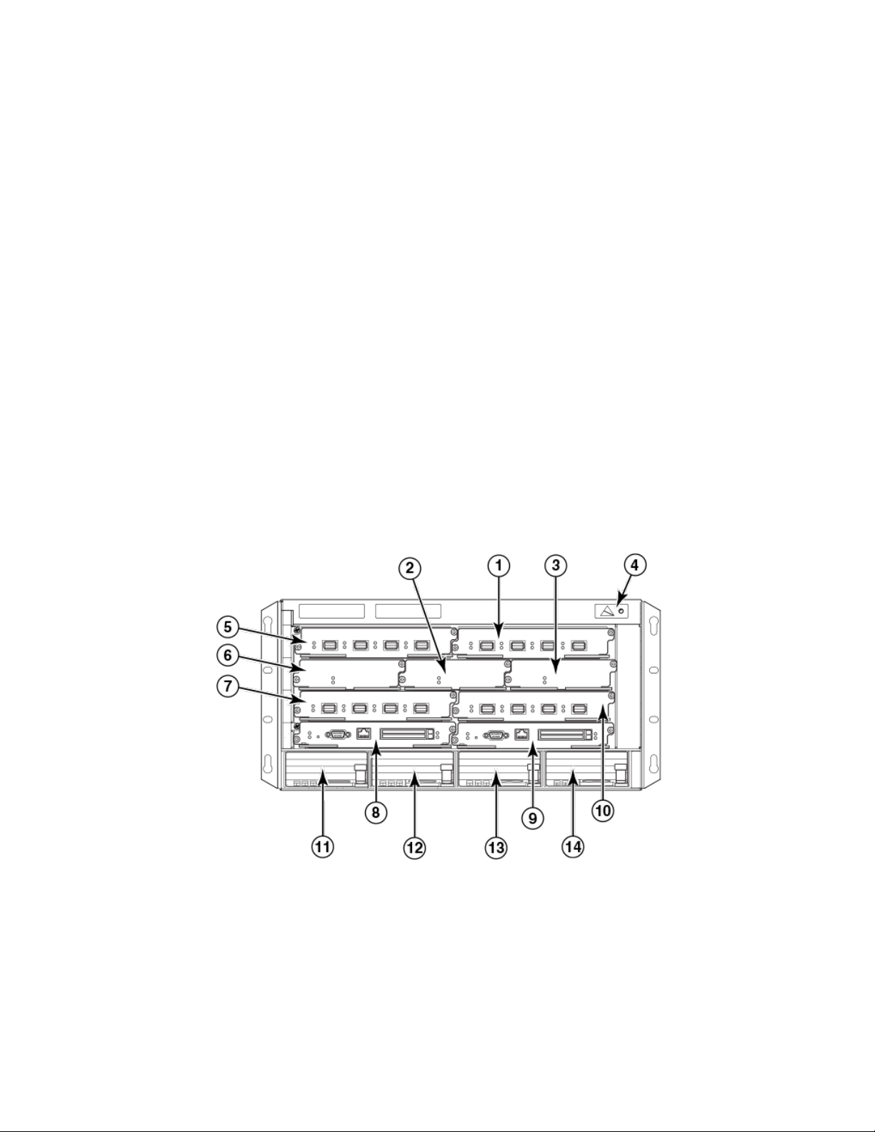
Hardware features
Brocade MLXe Series routers
Brocade MLXe Series routers are available in the following models:
• Brocade MLXe Series-4: 4 interface slots (refer to Brocade MLXe Series-4 router components on page 22)
• Brocade MLXe Series-8: 8 interface slots (refer to Brocade MLXe Series-8 router components on page 23)
• Brocade MLXe Series-16: 16 interface slots (refer to Brocade MLXe Series-16 router components on page 23)
• Brocade MLXe Series-32: 32 interface slots (refer to Brocade MLXe Series-32 router components on page 26)
The following content describes the components you can install in the router slots, and the numbering scheme used for those slots. For a
detailed list of components that ships with each router, refer to Brocade MLXe Chassis Bundles on page 277.
Brocade MLXe Series-4 router components
You can install the following components in the router slots:
• Up to two management modules (one active and one redundant).
• Up to three switch fabric modules.
• Up to four interface modules.
• Up to four power supplies (AC or DC).
For a detailed list of components that ships with each router, refer to Brocade MLXe Chassis Bundles on page 277.
FIGURE 1 Brocade MLXe Series-4 router
1. Interface slot 2
2. Switch fabric slot 2
3. Switch fabric slot 3
4. ESD connector
5. Interface slot 1
6. Switch fabric slot 1
7. Interface slot 3
8. Management slot 1
9. Management slot 2
10. Interface slot 4
11. Power supply 1
12. Power supply 2
13. Power supply 3
14. Power supply 4
22 53-1004203-04
Brocade NetIron MLXe Series Hardware Installation Guide
Page 23
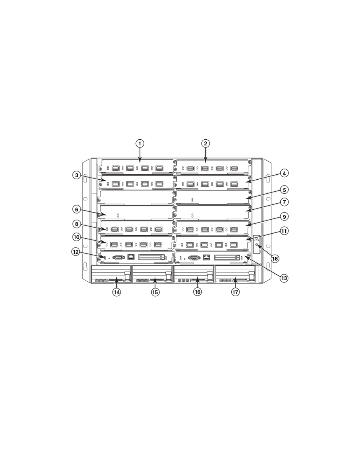
Brocade MLXe Series-8 router components
You can install the following components in the router slots:
• Up to two management modules (one active and one redundant).
• Up to three switch fabric modules.
• Up to eight interface modules.
• Up to four power supplies (AC or DC).
For a detailed list of components that ships with each router, refer to Brocade MLXe Chassis Bundles on page 277.
FIGURE 2 Brocade MLXe Series-8 router
Hardware features
1. Interface slot 1
2. Interface slot 2
3. Interface slot 3
4. Interface slot 4
5. Switch fabric slot 1
6. Switch fabric slot 2
7. Switch fabric slot 3
8. Interface slot 5
9. Interface slot 6
10. Interface slot 7
11. Interface slot 8
12. Management slot 1
13. Management slot 2
14. Power supply slot 1
15. Power supply slot 2
16. Power supply slot 3
17. Power supply slot 4
18. ESD connector
Brocade MLXe Series-16 router components
You can install the following components in the router slots:
• Up to two management modules (one active and one redundant).
Brocade NetIron MLXe Series Hardware Installation Guide
53-1004203-04 23
Page 24

Hardware features
• Up to four switch fabric modules.
• Up to 16 interface modules.
• Up to eight power supplies (AC or DC).
For a detailed list of components that ships with each router, refer to Brocade MLXe Chassis Bundles on page 277.
24 53-1004203-04
Brocade NetIron MLXe Series Hardware Installation Guide
Page 25
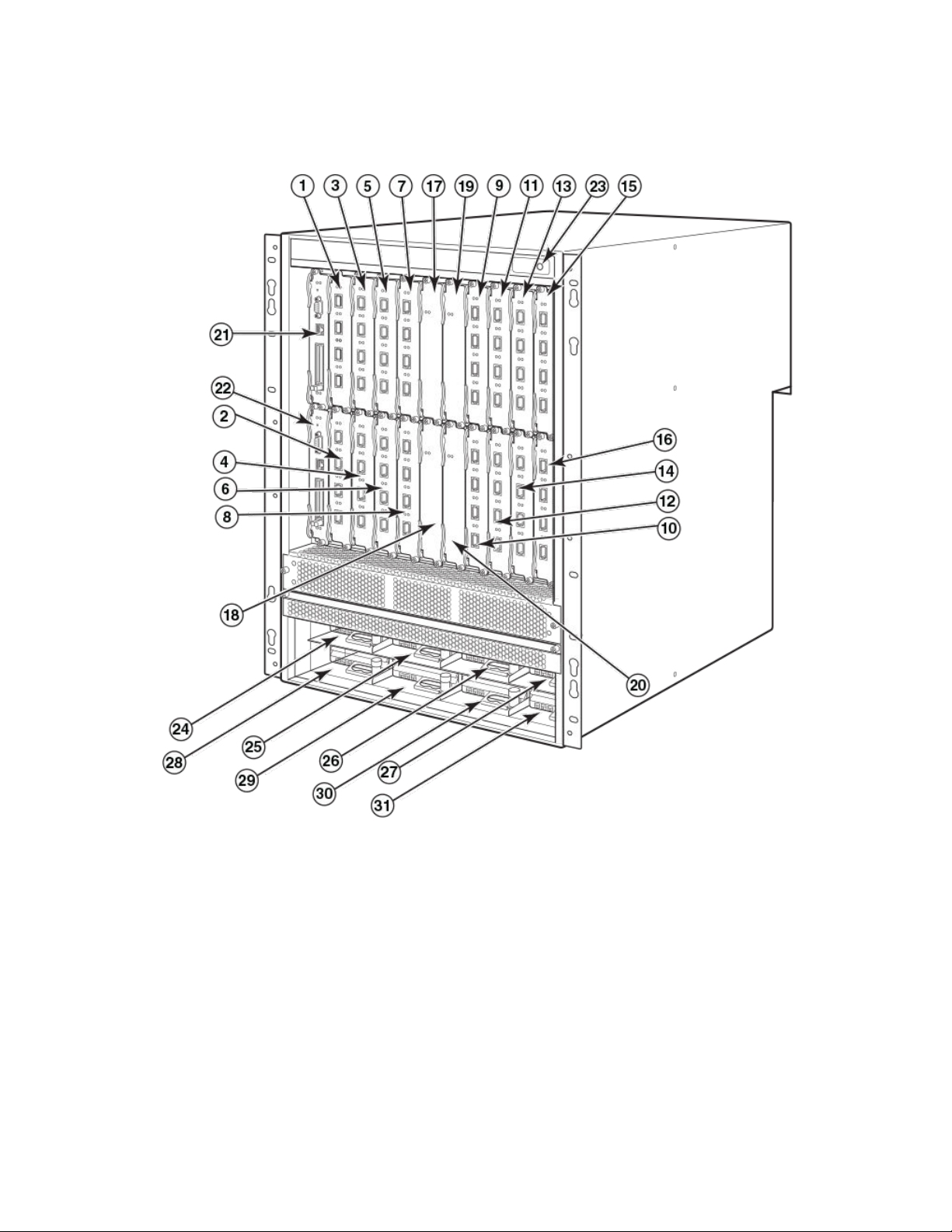
FIGURE 3 Brocade MLXe Series-16 router
Hardware features
Brocade NetIron MLXe Series Hardware Installation Guide
53-1004203-04 25
Page 26

Hardware features
1. Interface slot 1
2. Interface slot 2
3. Interface slot 3
4. Interface slot 4
5. Interface slot 5
6. Interface slot 6
7. Interface slot 7
8. Interface slot 8
9. Interface slot 9
10. Interface slot 10
11. Interface slot 11
12. Interface slot 12
13. Interface slot 13
14. Interface slot 14
15. Interface slot 15
16. Interface slot 16
Brocade MLXe Series-32 router components
You can install the following components in the router slots:
• – Up to two management modules.
– Up to eight switch fabric modules.
– Up to 32 interface modules.
– Up to eight power supplies (AC or DC).
17. Switch fabric slot 1
18. Switch fabric slot 2
19. Switch fabric slot 3
20. Switch fabric slot 4
21. Management slot 1
22. Management slot 2
23. ESD connector
24. Power supply slot 1
25. Power supply slot 2
26. Power supply slot 3
27. Power supply slot 4
28. Power supply slot 5
29. Power supply slot 6
30. Power supply slot 7
31. Power supply slot 8
For a detailed list of components that ships with each router, refer to Brocade MLXe Chassis Bundles on page 277.
26 53-1004203-04
Brocade NetIron MLXe Series Hardware Installation Guide
Page 27

FIGURE 4 Brocade MLXe Series-32 router
Hardware features
Brocade NetIron MLXe Series Hardware Installation Guide
53-1004203-04 27
Page 28

Router modules
1. Interface slot 1
2. Interface slot 2
3. Interface slot 3
4. Interface slot 4
5. Interface slot 5
6. Interface slot 6
7. Interface slot 7
8. Interface slot 8
9. Interface slot 9
10. Interface slot 10
11. Interface slot 11
12. Interface slot 12
13. Interface slot 13
14. Interface slot 14
15. Interface slot 15
16. Interface slot 16
17. Interface slot 17
18. Interface slot 18
19. Interface slot 19
20. Interface slot 20
21. Interface slot 21
22. Interface slot 22
23. Interface slot 23
24. Interface slot 24
25. Interface slot 25
26. Interface slot 26
27. Interface slot 27
28. Interface slot 28
29. Interface slot 29
30. Interface slot 30
31. Interface slot 31
32. Interface slot 32
33. Switch fabric slot 1
34. Switch fabric slot 2
35. Switch fabric slot 3
36. Switch fabric slot 4
37. Switch fabric slot 5
38. Switch fabric slot 6
39. Switch fabric slot 7
40. Switch fabric slot 8
41. Management slot 1
42. Management slot 2
43. Captive screws
44. ESD connector
45. Power supply slot 1
46. Power supply slot 2
47. Power supply slot 3
48. Power supply slot 4
49. Power supply slot 5
50. Power supply slot 6
51. Power supply slot 7
52. Power supply slot 8
Router modules
The Brocade MLXe Series routers support a number of management modules, interface modules, and switch fabric modules, as shown
in the following content.
Management modules
Brocade MLXe Series routers support the following management modules types.
• MR management module
• MR2 management module
The following table lists the management modules available for Brocade MLXe Series routers.
TABLE 6
Part number Description Notes
NI-MLX-MR (MR) Brocade MLXe Series and Brocade NetIron MLX
28 53-1004203-04
Management modules for all Brocade MLXe Series routers
Series management module, 1 GB SDRAM, dual
auxiliary ash slots, EIA or TIA-232 and
This module is no longer supported from
NetIron R05.7.xx.
Brocade NetIron MLXe Series Hardware Installation Guide
Page 29

TABLE 6 Management modules for all Brocade MLXe Series routers (continued)
Part number Description Notes
10/100/1000 Ethernet ports for out-of-band
management.
NI-MLX-32-MR (MR) Brocade MLXe Series-32 and Brocade NetIron
MLX Series-32 management module, 1 GB SDRAM,
dual auxiliary ash slots, EIA or TIA-232 and
10/100/1000 Ethernet ports for out-of-band
management.
NI-XMR-MR (MR) Brocade NetIron XMR Series management
module, 2 GB SDRAM, dual auxiliary ash slots, EIA or
TIA-232 and 10/100/1000 Ethernet ports for out-ofband management.
NI-XMR-32-MR (MR) Brocade NetIron XMR Series 32000
management module, 2 GB SDRAM, dual auxiliary
ash slots, EIA or TIA-232 and 10/100/1000
Ethernet ports for out-of-band management.
BR-MLX-MR2-M (MR2) MLXe/MLX Gen2 management (M) module for
4-, 8- and 16-slot systems. Includes 4 GB RAM, 1
internal compact ash drive (2 GB), 1 external compact
ash slot with included 2 GB card, RS-232 serial
console port and 10/100/1000 Ethernet port for
management.
BR-MLX-MR2-X (MR2) MLXe/XMR Gen2 management (X) module for
4-, 8- and 16-slot systems. Includes 4 GB RAM, 1
internal compact ash drive (2 GB), 1 external compact
ash slot with included 2 GB card, RS-232 serial
console port and 10/100/1000 Ethernet port for
management.
BR-MLX-32-MR2-M (MR2) MLXe/MLX Gen2 management (M) module for
32-slot systems. Includes 4 GB RAM, 1 internal
compact ash drive (2 GB), 1 external compact ash
slot with included 2 GB card, RS-232 serial console
port and 10/100/1000 Ethernet port for
management.
BR-MLX-32-MR2-X (MR2) MLXe/XMR Gen2 management (X) module for
32-slot systems. Includes 4 GB RAM, 1 internal
compact ash drive (2 GB), 1 external compact ash
slot with included 2 GB card, RS-232 serial console
port and 10/100/1000 Ethernet port for
management.
This module is no longer supported from
NetIron R05.7.xx.
This module is no longer supported from
NetIron R05.7.xx.
This module is no longer supported from
NetIron R05.7.xx.
You must use one of the relevant MR2 modules
starting from NetIron R05.8.00.
You must use one of the relevant MR2 modules
starting from NetIron R05.8.00.
You must use one of the relevant MR2 modules
starting from NetIron R05.8.00.
You must use one of the relevant MR2 modules
starting from NetIron R05.8.00.
Router modules
The management module controls the hardware components, runs the networking protocols, and provides the Real Time Operating
System (RTOS).
Each router requires one management module, and can accommodate a second module for redundancy. A redundant management
module works in conjunction with the active management module. If the active module becomes unavailable, the redundant
management module automatically takes over the system operation, minimizing system downtime. For information about the
redundancy feature, refer to the "Using a Redundant Management Module" chapter in the Brocade NetIron Switching Conguration
Guide.
Management modules are installed in dedicated slots marked M1 and M2. By default, the module installed in slot M1 is the active
management module.
Management modules are hot-swappable, which means you can remove and replace them without powering down the system.
Brocade NetIron MLXe Series Hardware Installation Guide
53-1004203-04 29
Page 30
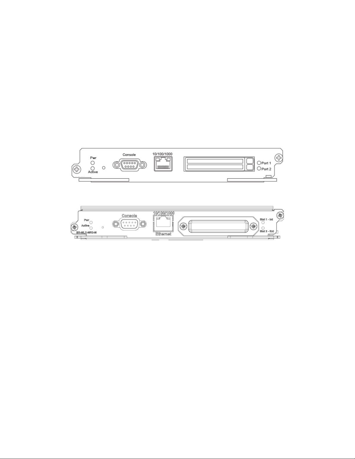
Router modules
NOTE
MR and MR2 management modules cannot be mixed in the same chassis.
NOTE
Prior to installing or replacing the MR2 management module, you must read the Hardware Installation Notes that shipped with
the hardware.
NOTE
Although management modules are designed to be hot-swappable, you must upgrade the software on all interface modules
and management modules to the appropriate software release before installing them. For more information on the appropriate
software release, refer to the Hardware Installation Notes that shipped with the management module.
FIGURE 5 MR management module front panel
FIGURE 6 MR2 management module front panel
The front panel of the management module contains the following features:
• Two auxiliary ash slots (available on MR management modules only)
• Compact ash slot (available on MR2 management modules only)
• Console port
• A 10/100/1000 Ethernet port
• Six LEDs
Auxiliary
Auxiliary ash slots support ash PC cards where you can store boot images, startup and running conguration les, and other system
les, in addition to what is stored in system ash memory. This allows you to perform system management tasks, such as copying les
between ash PC cards, or copying les between a ash PC card and ash memory.
For maximum performance, it is recommended that you use Brocade auxiliary ash cards, part number FLASH-PCC, which can be
ordered from Brocade. Brocade auxiliary ash cards ship with the label on the bottom of the card; take caution to insert the card with the
label on the bottom side.
ash slots
NOTE
Some older auxiliary ash cards can be inserted the wrong way in the slot because there is no indication in the card about which
is the right way. If you insert the card backwards, you will see continuous messages in the console and the card inserted/ card
removed syslog. If this occurs, you must remove the card and reinsert it the correct way.
30 53-1004203-04
Brocade NetIron MLXe Series Hardware Installation Guide
Page 31

Router modules
External compact ash
MR2 management modules do not contain an auxiliary ash slot. Instead, they contain a 2 GB internal compact ash card and an
external compact ash drive. MR2 management modules come with a factory installed compact ash card in the external compact ash
slot. The internal compact ash provides greater storage space for image retention, improving the upgrade process.
NOTE
Do not use compact ash cards over 2 GB; they will render the system unstable.The internal compact ash card cannot be
accessed for removal or replacement.
The external compact ash slot allows you to insert a 2 GB compact ash card. If you need to replace or add an additional compact ash
card, contact Brocade technical support.
Console port
The console port is a standard DB-9 serial connector through which you can attach a PC or terminal to
CLI.
NOTE
The console port interfaces the control plane only. It does not interface the data plane.
congure the router using the
10/100/1000 Ethernet port
Management modules contain a 10BaseT, 100BaseTX, or 1000BaseTX auto-sensing, auto-negotiating Ethernet port. This port has an
RJ-45 unshielded twisted pair (UTP) connector.
Typical uses of this port include, but are not limited to, the following:
• Connecting a PC to congure, monitor, and manage the system through a Telnet or SSHv2 connection.
• Connecting to the 10BaseT, 100BaseTX, or 1000BaseTX port for connectivity to your existing management network. You can
then access the router and congure, monitor, and manage the system from a management station.
NOTE
The existing management network into which you can connect the 10/100/1000 Ethernet port must be separate and isolated
from the network over which user packets are switched and routed. For information about the functionality of the management
port, refer to Understanding management port functions on page 196.
For information about connecting a PC to the 10/100/1000 Ethernet port, refer to Attaching a management station on page 171.
The out-of-band management port provides access to a separate system management network, and allows the ability to perform the
following tasks:
• Access the router through SSH, Telnet, the Web management interface, or the Brocade Network Advisor software.
• Access a TFTP server to perform system upgrade tasks.
• Congure SNMP polling access.
• Send SNMP traps.
• Send Syslog packets.
• Access the system through RADIUS AAA.
Management module LEDs
The LEDs on all management module models are the same. The following table describes the LEDs on the management module.
Brocade NetIron MLXe Series Hardware Installation Guide
53-1004203-04 31
Page 32

Router modules
TABLE 7 Management module LEDs
LED Position State Meaning
Port 1 and Port 2 Each adjacent to the auxiliary ash
slot that it represents
Active Lower Left On The module is functioning as the
Pwr Upper Left On The module is receiving power.
10/100/1000 Ethernet Port Above and right of RJ-45
connector
10/100/1000 Ethernet Port Above and left of RJ-45 connector On or blinking (Yellow) The port is transmitting and
On or blinking The software is currently accessing
the auxiliary ash card.
O The software is not currently
accessing an auxiliary ash card,
although there is one inserted in the
slot.
active management module.
O The module is functioning as the
redundant management module.
O The module is not receiving power.
On (Green) A link is established with the remote
port.
O No link is established with the
remote port.
receiving packets.
O for an extended period The port is not transmitting or
receiving packets.
Pre-installation notice for Brocade MLXe Series chassis bundles with MR2 management modules
The following conditions must be met for any chassis with a MR2 management module to operate properly.
• The MR2 module requires a minimum software version of R05.2.00b to operate. Do not attempt to downgrade the MR2
module to a release lower than R05.2.00b.
• MR2-M and MR2-X modules cannot be mixed together in any MLXe chassis
• MR and MR2 modules cannot be mixed together in any MLXe chassis
• Do not downgrade the MBRIDGE version on the MR2 module.
– The MR2 management module requires MBRIDGE version 36 or later for 4-, 8-, and 16-slot devices
– The MR2 management module requires MBRIDGE32 version 35 or later for 32-slot devices
• In certain module combinations, you will need to make sure the supported software is loaded.
Interface modules
Three generations of interface modules exist for Brocade MLXe Series routers.
The following table lists interface modules that are available for Brocade MLXe Series routers.
TABLE 8 Interface modules for all Brocade MLXe Series routers
SKU Ports Description Generation
BR-MLX-100GX2-CFP2-M 2 Brocade MLXe two (2)-port 100-
GbE (M) module with IPv4/IPv6/
MPLS hardware support. Requires
CFP2 optics. Supports 512K IPv4
routes in FIB. Requires high speed
switch fabric modules.
Gen 3
32 53-1004203-04
Brocade NetIron MLXe Series Hardware Installation Guide
Page 33

TABLE 8 Interface modules for all Brocade MLXe Series routers (continued)
SKU Ports Description Generation
BR-MLX-100GX2-CFP2-X2 2 Brocade MLXe two (2)-port 100-
GbE (X2) module with IPv4/IPv6/
MPLS hardware support. Requires
CFP2 optics. Supports
simultaneous 2M IPv4 and 0.8M
IPv6, or simultaneous 1.5M IPv4
and 1M IPv6 routes in FIB.
Requires high speed switch fabric
module.
BR-MLX-10Gx20-M 20 Brocade MLXe twenty (20)-port
10-GbE/1-GbE (M) combo
module with IPv4/IPv6/MPLS
hardware support. Requires SFP+
and SFP optics. Supports 512K
IPv4 routes in FIB. Requires high
speed switch fabric modules
BR-MLX-10Gx20-X2 20 Brocade MLXe twenty (20)-port
10-GbE/1-GbE (X2) combo
module with IPv4/IPv6/MPLS
hardware support. Requires SFP+
and SFP optics. Supports
simultaneous 2M IPv4 and 0.8M
IPv6, or simultaneous 1.5M IPv4
and 1M IPv6 routes in FIB.
Requires high-speed switch fabric
modules.
NI-MLX-10GX2 2 NetIron MLX Series 2-port 10-
GbE module with IPv4/IPv6/MPLS
hardware support. Requires XFP
optics.
NI-XMR-10GX2 2 NetIron XMR Series 2-port 10-
Gbps Ethernet module. Requires
XFP optics. IPv4, IPv6, MPLS
support.
BR-MLX-100GX-1 1 MLXE/XMR/MLX 1-port 100-
GbE (X) Module with IPv4/IPv6/
MPLS hardware support - requires
CFP optics. Supports 1M IPv4
routes in FIB in XMR mode and
512K IPv4 routes in MLX mode.
Requires high speed switch fabric
modules. License upgradable to 2ports on a MLXe.
BR-MLX-100GX-2 2 MLXE 2-port 100-GbE (X) Module
with IPv4/IPv6/MPLS hardware
support - requires CFP optics.
Supports 1M IPv4 routes in FIB in
XMR mode and 512K IPv4 routes
in MLX mode. Requires high speed
switch fabric modules.
NI-MLX-10GX4 4 NetIron MLX Series 4-port 10-
GbE module with IPv4/IPv6/MPLS
hardware support. Requires XFP
optics.
NI-XMR-10GX4 4 NetIron XMR Series 4-port 10-
GbE module with IPv4/IPv6/MPLS
Gen 3
Gen 3
Gen 3
Gen 1
Gen 1
Gen 2
Gen 2
Gen 1.1
Gen 1.1
Router modules
1
1
Brocade NetIron MLXe Series Hardware Installation Guide
53-1004203-04 33
Page 34

Router modules
TABLE 8 Interface modules for all Brocade MLXe Series routers (continued)
SKU Ports Description Generation
hardware support. Requires XFP
optics.
BR-MLX-10GX4-X 4 XMR/MLXe 4-port 10-GbE (X)
module with IPv4/IPv6/MPLS
hardware support. Requires XFP
optics. Supports 1M IPv4 routes in
FIB.
BR-MLX-10Gx4-X-ML 4 MLX/MLXe 4-port 10-GbE (ML)
module with IPv4/IPv6/MPLS
hardware support. Requires XFP
optics. Supports 512K IPv4 routes
in FIB. License upgradable to "X"
scalability (1M IPv4 routes in FIB).
BR-MLX-40Gx4-M 4 MLXe 4-port 40-GbE (M) module
with Layer 2, IPv4/IPv6, MPLS and
OpenFlow support. Supports 512K
IPv4 routes in FIB. Requires high
speed switch fabric modules and
QSFP+ optics.
NI-MLX-10GX8-M 8 Brocade NetIron MLX Series 8-
port 10-GbE (M) module with
IPv4/IPv6/MPLS hardware
support. Requires SFPP optics.
Supports 512K IPv4 routes in FIB.
Requires high speed switch fabric
modules
NI-MLX-10GX8-D 8 Brocade NetIron MLX Series 8-
port 10-GbE (D) module with IPv4/
IPv6 hardware support. Requires
SFPP optics. Supports 256K IPv4
routes in FIB. Does not support
MPLS. Requires high speed switch
fabric modules
BR-MLX-10GX8-X 8 MLXe/XMR 8-port 10-GbE (X)
module with IPv4/IPv6/MPLS
hardware support-requires SFPP
optics. Supports 1M IPv4 routes in
FIB. Requires high speed switch
fabric modules.
NI-MLX-1GX20-SFP 20 NetIron MLX Series 20-port
FE/GE (100/1000) module with
IPv4/IPv6/MPLS hardware
support. Requires SFP optics. Note:
Copper SFPs are supported at
1000Mbps only.
NI-XMR-1GX20-SFP 20 NetIron XMR Series 20-port
FE/GE (100/1000) module with
IPv4/IPv6/MPLS hardware
support. Requires SFP optics. Note:
Copper SFPs are supported at
1000Mbps only.
NI-MLX-1GX20-GC 20 NetIron MLX Series 20-port
10/100/1000 copper module with
IPv4/IPv6/MPLS hardware
support.
Gen 1.1
Gen 1.1
Gen 2
Gen 2
Gen 2
Gen 2
Gen 1
Gen 1
Gen 1
1
1
1
34 53-1004203-04
Brocade NetIron MLXe Series Hardware Installation Guide
Page 35

TABLE 8 Interface modules for all Brocade MLXe Series routers (continued)
SKU Ports Description Generation
NI-XMR-1Gx20-GC 20 NetIron XMR Series 20-port
10/100/1000 copper module with
IPv4/IPv6/MPLS hardware
support.
BR-MLX-1GCX24-X 24 XMR/MLXE 24-port
10/100/1000 Copper (RJ-45)
Module with IPv4/IPv6/MPLS
hardware support. Supports 1M
IPv4 routes in FIB.
BR-MLX-1GCX24-X-ML 24 MLX/MLXE 24-port
10/100/1000 Copper (RJ-45)
Module with IPv4/IPv6/MPLS
hardware support. Supports 512K
IPv4 routes in FIB. License
Upgradable to "X" scalability (1M
IPv4 routes in FIB).
BR-MLX-1GFX24-X 24 XMR/MLXE 24-port 1-GbE Fiber
(SFP) Module with IPv4/IPv6/
MPLS hardware support. Supports
1M IPv4 routes in FIB.
BR-MLX-1GFX24-X-ML 24 MLX/MLXE 24-port 1-GbE Fiber
(SFP) Module with IPv4/IPv6/
MPLS hardware support. Supports
512K IPv4 routes in FIB. License
Upgradable to "X" scalability (1M
IPv4 routes in FIB).
BR-MLX-10GX24-DM 24 MLXe 24-port 10-GbE Module
with IPv4/IPv6/MPLS hardware
support - requires SFPP optics.
Bandwidth up to 200Gbps per
module. Supports 256K IPv4
routes.
NI-MLX-1GX48-T-A 48 NetIron MLX Series 48-port
10/100/1000Base-T, MRJ21
module with IPv4/IPv6/MPLS
hardware support. Requires high
speed fans NIBI-16-FAN-EXH-A
on MLX-16.
1
Support is discontinued for Gen 1 cards (20x1G all avors; 4x10G all avors except 4x10-X; and 2x10G all avors).
Gen 1
Gen 1.1
Gen 1.1
Gen 1.1
Gen 1.1
Gen 1.1
Gen 1.1
Router modules
1
Depending on your router model, you can install up to 32 single-slot interface modules, or 16 double-slot interface modules.
Interface modules are hot-swappable, which means you can remove and replace them without powering down the system.
NOTE
Specic information regarding RAD optics conguration on the Brocade MLXe Series platforms has been documented in the
RAD optics Solutions test report. Please work with your account team to gain access to the document.
2x100GbE CFP2 optics based high density module
The 100GbE 2-port CFP2 optics based high density blade is a half slot module card for the MLXe chassis.
The 2x100GbE CFP2 interface module is supported on all Brocade MLXe Series routers.
Brocade NetIron MLXe Series Hardware Installation Guide
53-1004203-04 35
Page 36

Router modules
NOTE
The 100G CFP2 ER4 optic is supported on this card for hardware revision 15 or later only. To check the version of the line
card, enter the show version slot slot-number command. The version number must be 15 or later. The folllowing example
shows the version as version 15 in the underlined command output.
MLX#show version slot 4
SL 4: BR-MLX-100Gx2-CFP2 2-port 100GbE Module
(Serial #: CWC0440K027, Part #: 60-1002934-15)
=====================================================
The 2x100GbE CFP2 based high density blade has the following features:
• 2x100GbE CFP2 optics half-slot ports
• 4GB DDR3 SDRAM (800MB Data Rate)
• 512K Flash Memory 2x16MB Code, 4MB Boot
• 64MB Flash Memory for Application Code
• PCI bus interface (PBIF) FPGA for PCIe Interface and STATS
• Hot Pluggable
• Power Consumption: 360W
• XPP FPGA for packet processing
• Temperature sensor, strategically located on the PCBA
• Power, port, and status LED indicators
• Link Status per port
• JTAG support
• Temperature monitoring I2C Management Interface
• Real Time Clock
• Supports 32 GPIO
• Supports 9 temperature sensors
The 2x100GbE CFP2 based high density blade provides the following support:
• Extended VLAN statistics, sFlow monitoring, Optical Monitoring, CAM MIB, entity MIB, snAgentCpuUtilTable and system MIBs.
• snAgentCongModuleTable, snSwIfInfoTable, snAgentBrdTable and brcdEntityOIDMIB.
• NP and TM counters and statistics.
• LP-Auto Upgrade.
• 4GB DDR3 SDRAM.
NOTE
Web Management Front Panel is not supported for the 2x100GbE CFP2 card.
NOTE
For NetIron 5.7 release only: 2GB of SDRAM memory is usable out of 4GB.
Trac Manager (TM) trac behavior for the 2x100GbE CFP2 card is as follows:
• E-Chassis and hSFMs are required with the 2x100GbE CFP2 module.
• Each 2x100GbE CFP2 TM can support one full 100Gbps wire speed ports.
• For best performance, Turbo mode is recommended; 1024B credit size; and full fabric connectivity.
36 53-1004203-04
Brocade NetIron MLXe Series Hardware Installation Guide
Page 37

• Performance in Turbo mode:
– Line-rate with all SFMs installed except for some small packet sizes
– No line-rate without all SFMs installed.
• Performance in non Turbo mode:
– No line-rate even with all SFMs installed.
NOTE
Dynamic port conguration for the 2x100GbE CFP2 based high density blade chassis is shown in the topic 2x100GbE CFP2
Dynamic Port Conguration on page 275.
FIGURE 7 2x100GbE CFP2 interface module front panel
Router modules
1. Pwr LED - if green: All power rails are functional and module is receiving
power. If not lit (o): One or more power rails have failed and module is not
receiving power.
2. 1 Link/Act LED: If green: CFP2 port 1 is functional. If not lit (o): CFP2
port 1 is not active.
3. 2 Link/Act LED: If green: CFP2 port 2 is functional. If not lit (o): CFP2
port 2 is not active.
2x100GbE CFP2 LED indicators and chassis support tables
LED indicators for the 2x100GbE CFP2 based high density blade indicate the status of each port, as described in the following table.
TABLE 9 2x100GbE CFP2 LED Indicators
LED Function/state Location Meaning Possible cause
Power module state (LED)
Controlled by the downloader FPGA; this
LED is hardware controlled and is not
software accessible.
Link/Act Adjacent to each port. GREEN: All ports are functional. Port is enabled and link is up.
Chassis support for the 2x100GbE CFP2 based high density blade is shown in the following table.
TABLE 10
Ports Chassis Supported Description
2x100GbE CFP2 MLXe Support in MLXe.
2x100GbE CFP2 Chassis Support
Left side of module GREEN: All power rails are
functional and module is
receiving power.
OFF: One or more power rails
have failed and module is not
receiving power.
OFF: One or more ports have
failed.
Power rails are enabled.
Power rails are disabled.
Port is disabled.
Brocade NetIron MLXe Series Hardware Installation Guide
53-1004203-04 37
Page 38

Router modules
TABLE 10 2x100GbE CFP2 Chassis Support (continued)
Ports Chassis Supported Description
NOTE
XMR not supported.
CFP2 optics for 2x100GbE
The 2x100GbE CFP2 interface module is 802.3ba compliant, supports CFP2-based optics, and can be used with existing Brocade
MLXe Series interface modules. The 2x100GbE interface module requires high-speed fabric modules.
NOTE
2x100GbE CFP2 interface modules will boot in turbo mode if all modules in the chassis are Gen-2 modules.
You must insert CFP2-compliant ber-optic transceivers in each port you intend to use. CFP2-compliant transceivers provide an optical
or physical medium-dependent (PMD) interface for single- or multi-mode ber that can be used with either the LAN physical layer (PHY)
or WAN physical layer (WAN PHY).
For a list of supported 2x100GbE CFP2-compliant ber-optic transceivers that are available from Brocade, refer to the latest version of
the Brocade Optics Family Data Sheet.
For more information about ber-optic transceivers and associated cabling, refer to Installing a ber-optic transceiver on page 197.
Power supply requirements for 2x100GbE modules
For power supply requirements for the 2x100GbE modules, refer to Hardware
Specications on page 271.
38 53-1004203-04
Brocade NetIron MLXe Series Hardware Installation Guide
Page 39

PBIF Recovery
In the event PBIF gets locked up, PBIF recovery is activated by default with the option to activate PBIF recovery through the
system-monitoring pbif lp-reset-recovery command.
Syntax
system-monitoring pbif lp-reset-recovery
no system-monitoring pbif lp-reset-recovery
Command Default
PBIF is locked up.
Examples
In the event PBIF is locked up, PBIF recovery is activated by default. However, if necessary you may activate PBIF recovery
through the system-monitoring pbif lp-reset-recovery command.
device# config
device(config)# system-monitoring pbif lp-reset-recovery
device(config)# exit
device# write memory
device# reload
Router modules
To deactivate PBIF recovery perform the no system-monitoring pbif lp-reset-recovery command.
device# config
device(config)# no system-monitoring pbif lp-reset-recovery
device(config)# exit
device# write memory
device# reload
History
Release version Command history
5.7.00 This command was introduced.
2x100GbE CFP2 P2010 specications
P2010 specications are shown for the 2x100GbE CFP2 optics based high density blade.
TABLE 11 2x100GbE CFP2 P2010
Component Gen 2 Cards 2x100GbE CFP2 Cards
Processor MPC8548E P2010
Processor Version 0x8021_0022 0x8021_1051
System Version 0x8031_0021 0x80e3_0021
Core Version E500V2 E500V2
Clock Speed 1.3GHz 1.2Ghz
Cache Support 32KB L1 instruction cache
Specications
32KB L1 data cache
32KB L1 instruction cache
32KB L1 data cache
Brocade NetIron MLXe Series Hardware Installation Guide
53-1004203-04 39
Page 40

Router modules
TABLE 11 2x100GbE CFP2 P2010 Specications (continued)
Component Gen 2 Cards 2x100GbE CFP2 Cards
512KB L2 cache 512KB L2 cache
Security Engine Yes Yes, enhanced SEC2 Interface
DDR Support DDR/DDR2 DDR2/DDR3
2x100GbE CFP2 DDR3 SDRAM memory specications
DDR3 SDRAM memory for the 2x100GbE CFP2 optics based high density blade, is shown in the following table.
TABLE 12 2x100GbE CFP2 DDR3 SDRAM Memory Specications
Feature Gen 2 Cards 2x100GbE Cards
DDR type DDR2 DDR3
DDR size 2 GB 4GB
NOTE
For NetIron 5.7 release only: 2GB of
SDRAM memory is usable out of
4GB.
Data rate Up to 533 Mbps Up to 800 Mbps
BR-MLX-10GX20-X2 and BR-MLX-100GX2-CFP2-X2 Router Software
BR-MLX-10GX20-X2 and BR-MLX-100GX2-CFP2-X2 scalability for IPv4 and IPv6 routes
In release 5.8.00a, the maximum number of routes supported with the BR-MLX-10GX20-X2 and BR-MLX-100GX2-CFP2-X2
modules has been scaled to 2.4M for IPv4 and 1.8M for IPv6. The -X2 scaling software is compatible with both MR2-M and MR2-X
management modules so that you can deploy M, X, and -X2 modules in the same device.
NOTE
MR2 management modules require High Speed Switch Fabric modules.
40 53-1004203-04
Brocade NetIron MLXe Series Hardware Installation Guide
Page 41

show cam-partition usage
The show cam-partition usage command displays the CAM partition usage. IP CAM region is divided into partition and subpartitions, with the super netting feature managing entries within these partitions and sub-partitions to achieve LPM (longest
prex match). Entries are shued across the sub-partition based on prex length.
Syntax
show cam-partition usage
Examples
device#sh cam-partition usage
CAM partitioning profile: multi-service-3
XPP44GEX 0:
[IPV6 Session] 8192(size), 8192(free), 0. 0%(used)
:IPv6 Multicast: 2048(size), 2048(free), 0. 0%(used)
:Receive ACL: 0(size), 0(free), 0. 0%(used)
:Rule ACL: 6144(size), 6144(free), 0. 0%(used)
[Session] 32768(size), 32767(free), 0. 0%(used)
:IP Source Guard Denial: 0(size), 0(free), 0. 0%(used)
:IP Source Guard Permit: 0(size), 0(free), 0. 0%(used)
:Rule-based ACL: 23552(size), 23552(free), 0. 0%(used)
:Broadcast ACL: 0(size), 0(free), 0. 0%(used)
:Receive ACL: 1024(size), 1023(free), 0. 9%(used)
:IP Multicast: 8192(size), 8192(free), 0. 0%(used)
:IP Multicast 1G: 0(size), 0(free), 0. 0%(used)
:IP Multicast 2GM: 0(size), 0(free), 0. 0%(used)
:Open Flow CatchAll: 0(size), 0(free), 0. 0%(used)
:Open Flow UnProtected: 0(size), 0(free), 0. 0%(used)
:Open Flow Normal: 0(size), 0(free), 0. 0%(used)
:Open Flow Protected: 0(size), 0(free), 0. 0%(used)
[MAC] 131072(size), 131067(free), 0. 0%(used)
:Protocol: 10(size), 5(free), 50. 0%(used)
:Forwarding: 131024(size), 131024(free), 0. 0%(used)
:Flooding: 8(size), 8(free), 0. 0%(used)
:Port BUM RL: 30(size), 30(free), 0. 0%(used)
Router modules
[Out Session] 32768(size), 32768(free), 0. 0%(used)
[Out V6 Session] 8192(size), 8192(free), 0. 0%(used)
[Internal Forwarding Lookup] 131072(size), 131072(free), 0. 0%(used)
:IFL Main: 131062(size), 131062(free), 0. 0%(used)
:IFL Openflow CatchAll: 10(size), 10(free), 0. 0%(used)
[IP VPN] 196608(size), 196608(free), 0. 0%(used)
[IP] 262144(size), 262123(free), 0. 0%(used)
[IPV6] 65536(size), 65534(free), 0. 0%(used)
[IPV6 VPN] 131072(size), 131068(free), 0. 0%(used)
History
Release version Command history
NetIron R05.8.00 This command was introduced.
Brocade NetIron MLXe Series Hardware Installation Guide
53-1004203-04 41
Page 42

Router modules
2x100G XPP ILKN monitoring
The 2x100G XPP ILKN monitoring feature will monitor CRC errors in the Interlaken link / interface between XPP1 and XPP2 in 2 packet
processors for the 2x100G Ibzian card.
In 2x100G cards, CRC errors on the Interlaken link between iXPP1 and iXPP2 in the packet processor result in packet drops. The
2x100G XPP ILKN monitoring feature will generate syslog and SNMP traps if software reads more than congured drops on ILKN links
between iXPP1 and iXPP2. Syslog and SNMP traps display the number of packet drops in the Interlaken interface and CRC errors in
lane groups.
Two 100G ports are available. For each port:
• One XPP (with two internal ingress XPPs, iXPP1, iXPP2, and an egress XPP) is present to perform packet processing. This
feature polls for Interlaken errors between ingress XPPs, iXPP1, and iXPP2.
• Two identical CXPP1x100G packet processors are present to perform 200Gbps packet processing.
SYSLOG and SNMP traps are generated if packet drops result from CRC errors in the Interlaken link / interface between iXPP1 and
iXPP2. The aected ports are shutdown if the Interlaken link / interface was congured through the new CLI conguration command
based on the following factors:
• The option to shutdown the aected ports is congured using the new global conguration command.
• The option to disable the feature is congured using the new global conguration command.
Syslog and SNMP traps are generated once the packets drop are seen because of Interlaken CRC errors. The syslog/SNMP trap is
generated once every 3 minutes with the following information:
• Indicating the number of packet drops and CRC errors in each lane group.
• Indicating if ports are not disabled by the port shut down option.
42 53-1004203-04
Brocade NetIron MLXe Series Hardware Installation Guide
Page 43

sysmon np interlaken-monitor
The global conguration command sysmon np interlaken-monitor {crc-port-shutdown | disable} is used to shut down available
100G ports if drops in the ILKN interface are more than the congured number of drops (crc-port-shutdown); or disable the
feature (disable).
Syntax
sysmon np interlaken-monitor crc-port-shutdown
no sysmon np interlaken-monitor crc-port-shutdown
sysmon np interlaken-monitor disable
no sysmon np interlaken-monitor disable
Command Default
By default, the feature is enabled to poll ILK2 DROP COUNT register 0x200f4 every 30 seconds, and if there are 10 drops or
more on ILK2 DROP COUNT register 0x200f4, then syslog and SNMP traps are generated.
Parameters
crc-port-shutdown
Port shutdown option is set globally for all the 2x100G cards available in the MLX. The crc-port-shutdown global
conguration command will be used to shut down the available 100G ports if the drops in ILKN interface are more
than the congured number of drops. (No command is available to disable the port shutdown option.)
Router modules
Examples
disable
Interlaken monitoring feature is disabled globally for all the 2x100G cards available in the MLX. The disable global
conguration command will be used to disable the feature. This command will be used disable the feature in all LP's
across resets. (No command is available to enable the Interlaken monitoring option for all the 2x100 LPs available in
the MLX.)
The port shutdown option is set.
device(config)#sysmon np interlaken-monitor crc-port-shutdown
The Interlaken monitoring feature is disabled in all LPs.
device(config)#sysmon np interlaken-monitor disable
The show interface Ethernet <slot/port> CLI command will display the reason for port down as Interlaken CRC error.
device(config)#show int e 1/1
100GigabitEthernet1/1 is down(interlaken crc error), line protocol is down
STP Root Guard is disabled, STP BPDU Guard is disabled
NP transmitted 0 packets, Received from TM 0 packets
Brocade NetIron MLXe Series Hardware Installation Guide
53-1004203-04 43
Page 44

Router modules
The show sysmon cong CLI command will display the conguration details for ILKN CRC monitoring. Action is none by
default. If sysmon np Interlaken-monitor crc-port-shutdown is congured, action will be displayed as DISABLE-PORTS.
Mode will be displayed as POLLING by default and if the feature is disabled, then it will displayed as DISABLED. Poll period will
display the value as 30 seconds, which is the global default conguration for this feature.
device(config)#show sysmon config
------------------------+-------+--------------------------+----------+-----------+-----------+-----------------+--------------------EVENT |ACTION|SLOTS |MODE |POLL PERIOD| THRESHOLD |LOGBACK-OFF
| | | |
(SEC) | #(PER POLL |
| | | | in
#POLL) | |
-----------------------+--------+--------------------------+-------------+------------------+-------------------+--------------------NP ILKN |NONE | BR-MLX-100Gx2 |POLLING | 30 | N/A | N/A
Monitoring
History
Release version Command history
NetIron Release 5.8.00 These commands were introduced.
CPU threshold monitoring
CPU threshold monitoring generates a syslog when the hold time of any task exceeds the congured threshold time, for the purpose of
troubleshooting to discover the reason for a CPU high condition (if applicable).
On encountering a high CPU condition, the resulting command output is not captured to determine the application that resulted in a high
CPU condition. In many instances, the system recovers from high CPU conditions on its own. Syslog is a mechanism which can log
tasks that cause high CPU conditions.
Syslog is generated when the hold time of any task exceeds the congured threshold time in active MP and LPs. Throttling allows the
syslog to display the number of occurrences of high CPU conditions for a particular task in 5 minute intervals. Additional considerations
include the following:
• This feature is enabled by conguring the sysmon task-threshold time global conguration command and is not available by
default.
• The threshold time is congured using the sysmon task-threshold time global conguration command for active MP and all
LPs, and is available across resets. The range of user congured threshold time is from 20ms to 1000ms. Default value
recommended is 60ms.
44 53-1004203-04
Brocade NetIron MLXe Series Hardware Installation Guide
Page 45

sysmon task-threshold
The threshold time is congured using the global conguration command sysmon task-threshold <time> for the active
MP and all LPs, and will be available across resets.
Syntax
sysmon task-threshold time
no sysmon task-threshold time
Used to uncongure the threshold value.
Parameters
time
Sets the threshold-time in milliseconds.
Modes
Global conguration
Examples
The following conguration example congures the task-threshold to default 60ms:
Router modules
device(config)#sysmon task-threshold 60
Task threshold-time is set to default value 60ms.
The following
device(config)#sysmon task-threshold 50
Task threshold-time is set to 50ms.
When hold time exceeds the
Nov 26 14:12:11:I:System: High CPU condition on MP, task name=sfm_mgr, max hold time=29ms, count =11
Nov 26 14:07:11:I:System: High CPU condition on MP, task name=sfm_mgr, max hold time=29ms, count =1
conguration example sets the task-threshold to 50ms:
congured threshold, i.e. 20ms for sfm_mgr task, the below syslog gets generated:
History
Release version Command history
R05.8.00 This command was introduced.
MLXe BR-MLX-10Gx4-M IPsec and IKEv2
NetIron MLXe is located on the perimeter of connections to external networks. Encryption and decryption is supported for IPv4 unicast
data and control packets transmitted or received from external networks, using IPSec FPGA and IKEv2 protocols for the MLXe BRMLX-10Gx4-M-IPSEC.
The Public Key Infrastructure (PKI) provides a security infrastructure for secure communication. Each PKI peer holds a Digital Certicate
which holds multiple attributes that ensure the entity can be trusted, and can support secure communication.
• IPSec FPGA protocol for the MLXe BR-MLX-10Gx4-M-IPSEC provides hardware based data encryption and decryption.
• IKEv2 protocol for the MLXe BR-MLX-10Gx4-M-IPSEC is used to setup and manage secure tunnels across external
networks.
PKI uses the asymmetric encryption algorithm; two dierent keys are used to encrypt and decrypt data. The key pair consists of a private
key and a public key. The private key must be kept secret, while the public key can be distributed. Data encrypted by one of the two keys
can only be decrypted by the other. Data encrypted with a public key cannot be decrypted using a public key and vice versa. Users of a
public key are condent that the associated private key is owned by the correct remote subject.
Brocade NetIron MLXe Series Hardware Installation Guide
53-1004203-04 45
Page 46

Router modules
Encryption and Decryption of IPv4 Unicast Data and Control Packets
Features include for encryption and decryption of IPv4 unicast data and control packets include IKEv2 on MP; IPSec FPGA protocol;
IKEv2 protocol support; and PKI checks for certicate presence.
Major enhancements to support encryption and decryption of IPv4 unicast data and control packets transmitted or received from
external networks include:
• IPSec FPGA protocol using a new 4x10G/1G and 4x1G IPSec line card, developed to provide hardware based data encryption
and decryption at line rate of 44GBe. This card has free scale P2010 CPU with Security Engine 3.1x.
• IKEv2 protocol support to setup and manage secure tunnels across the external network.
• PKI support for authentication of endpoints of tunnel using digital certicates.
NOTE
The PKI module needs to run over HTTP, so it will be running as a separate task on MP.
IKE or another module should not store the PKI certicates for later reference. Whenever needed, the PKI module
should be queried with the certicate DN or Subject's alternate name.
• Manual PKI is supported, and OCSP and SCEP are not supported (for NetIron Release 5.8.00).
IKEv2 Authentication
When IKEv2 authentication is congured and the method (remote or local) is ECDSA, the CA certicates are retrieved and downloaded to
LPs where IKE will store these certicates. This is done even if the peer is not up, such as during peer init. This data is required or SA-
INIT cannot be completed.
NOTE
The new PKI feature in NI Release 5.8.00 will only be used for setting up the IKEv2 session.
When a peer is created and auth method is ECDSA IKE checks its database to ascertain if the CA and its self certicate are available.
The following certicate payload encoding is supported:
Certicate Type Value
X.509 Certicate – Signature 4
Hash and URL of X.509 certicate 12
OCSP content 14
During the IKEv2 exchange, when two peers are establishing a tunnel, each peer will receive a certicate from the other IKE peer. In the
IKE, the certicates can be sent in two ways: Inline certicate and HTTP and URL format.
NOTE
IKE or another module should not store the PKI certicates for later reference. Whenever needed, the PKI module should be
queried with the certicate DN or Subject alternate name.
46 53-1004203-04
Brocade NetIron MLXe Series Hardware Installation Guide
Page 47

IPsec and IKEv2 conguration
Create a VTI interface by creating a tunnel interface and setting the mode of the tunnel to IPsec IPv4.
To create a tunnel interface and set the mode of the tunnel to IPsec IPv4, perform the following task.
1. Create a VTI interface by completing the following steps:
a) Create a VTI interface by entering the interface tunnel x command, where x is the tunnel number.
b) Set the mode of the tunnel to IPsec IPv4 by entering the tunnel mode ipsec ipv4command.
2. Congure the following values, if the default values are not acceptable.
• IKE Proposal
• IKE Policy
• IKE Prole
• IKE Authentication
• IPSEC Proposal
• IPSEC Prole
3. Bind the IPsec Prole to the VTI interface using the tunnel protection ipsec prole prolename command.
Router modules
Conguring Global IKEv2 Options
Congure global IKEv2 options that are independent of peers. All the global IKE commands start with prex ikev2.
IKEv2 Option Description
ikev2 retry-count <number> Maximum number of attempts to retransmit a message. Default 5.
NOTE
Range is 1 to 10.
ikev2 exchange-max-time
<seconds>
ikev2 retransmit-interval <time> IKEv2 message resend delay, in seconds. This is the time that the IKEv2 task is to wait before attempting the rst
ikev2 http-url-cert Enables the HTTP CERT support. HTTP CERT is disabled by default. If enabled then
ikev2 cookie-challenge <number>Enabled an IKEv2 cookie challenge only when the number of half-open IKE SAs crosses the congured number.
Maximum setup time for an exchange, in seconds. Default 30 seconds.
NOTE
Range is 0 to 300 seconds.
resend of a packet. Default is 5 seconds. Retransmit interval will increase exponentially.
NOTE
Range is 1 to 60 seconds.
HTTP_CERT_LOOKUP_SUPPORTED should be send along with the CERT_REQ payload. Default is disabled.
Default is disabled.
NOTE
Range is 1 to 2000 (max number of SA supported).
ikev2 limit { max-in-negotiationsa limit | max - sa limit }
ikev2 Allow duplicate ike-sa For a given source/destination and IKE Prole, if multiple IKE SA can be created. This will be applicable only for
Brocade NetIron MLXe Series Hardware Installation Guide
53-1004203-04 47
max-in-negotiation-sa limit — Limits the total number of in negotiation IKEv2 SAs on the node. Default is 256.
max-sa limit — Limits the total number of IKEv2 SAs on the LP. Default is 256.
NOTE
For both limits the range is 1 to 256 (max SAs supported).
incoming IKE session. Default is disabled. This will be used for inter-op with other vendors.
Page 48

Router modules
IKEv2 Option Description
NOTE
Not supported for NI R05.8.00 release.
ikev2 fragmentation [ mtu-size ] (Optional) To support fragmentation of IKEv2 message into small parts to avoid UDP level fragmentation. Default
it is disabled. It is at the global level because the routing can change, and we should be able to estimate what will
be the maximum size for the router. Range should be between 68 to 1500.
NOTE
Not supported for NI R05.8.00 release.
Conguring the IKEv2 Proposal
IKEv2 Proposal sets the congurable parameters which are exchange during IKEv2 peer negotiation during the rst phase.
The default IKEv2 proposal requires no conguration and its parameters are as follows:
• Encryption: aes-cbc-256
• PRF: sha384
• Integrity: sha384
• dh-group: 20
This default IKEv2 proposal will be known as ikev2-default-proposal.
The following commands are available to congure the proposals manually, if you do not want to use the default proposal.
NOTE
The default proposal command will only be available if additional cryptographic algorithms are supported, as currently there is
no requirement to support them in NI Release 5.8.00.
IKEv2 Option Description
ikev2 proposal <name> Congure IKE proposal Parameter, enter ikev2 proposal <name> cong mode.
dhgroup {1} {2} {5} {14} {15} {16}
{19} {20} {24}
Group used for Die-Hellman negotiations. Allowed values are:
• 1 — 768-bit DH
• 2 — 1024-bit DH
• 5 — 1536-bit DH
• 14 — Species the 2048-bit DH group.
• 15 — Species the 3072-bit DH group.
• 16 — Species the 4096-bit DH group.
• 19 — Species the 256-bit elliptic curve DH (ECDH) group.
• 20 — Species the 384-bit ECDH group.
• 24 — Species the 2048-bit DH/SA group.
NOTE
For the rst release, only DH-group 14, 19, and 20 will be supported. Support for other DH groups
will be considered for inclusion in the next major release.
prf { sha384 | sha256 } Hash algorithm to be used to generate key material for IKE SA negotiation. Multiple algorithms may be specied,
separated by commas.
encryption {3des} {aes-cbc-128}
{aes-cbc-192} {aes-cbc-256}
48 53-1004203-04
Encryption algorithm to be used to protect IKEv2 data. Multiple algorithms may be specied. Allowed values are:
• 3des
• aes-cbc-128
• aes-cbc-192
Brocade NetIron MLXe Series Hardware Installation Guide
Page 49

IKEv2 Option Description
• aes-cbc-256
Router modules
NOTE
For the rst release, only aes-cbc-128 and aes-cbc-256 will be supported. Support for other
encryption for IKEv2 will be considered for inclusion in the next major release.
integrity {sha1} {sha256}
{sha384} {sha512}
Integrity algorithm to be used to protect IKEv2 data. Multiple algorithms may be specied. The following are
supported:
• sha1 — species SHA-1 (HMAC variant) as the hash algorithm.
• sha256 — species SHA-2 family 256-bit (HMAC variant) as the hash algorithm.
• sha384 — species SHA-2 family 384-bit (HMAC variant) as the hash algorithm.
• sha512 — species SHA-2 family 512-bit (HMAC variant) as the hash algorithm.
NOTE
For the rst release, only sha256 and sha384 will be supported. Support for other crypto for IKEv2
will be considered for inclusion in the next major release.
Conguring the IKEv2 Policy
After you create the IKEv2 proposal, the proposal must be attached to a policy to pick the proposal for negotiation.
The IKE policy states which security parameters will be used to protect IKE negotiations. An IKEv2 policy must contain at least one
proposal to be considered as complete. It can have local-address and VRF statements which are used as selection criteria to select a
policy for negotiation. During the initial exchange, the local address and the VRF of the negotiating SA are matched with the policy and
the proposal is selected.
There will be a default IKEv2 policy named ikev2-default-policy and it will have the following parameters:
• Proposal: ikev2-default-proposal
• local_address: not set, match all local addresses
• VRF: not set so will match any-vrf
If no suitable IKE policy is found, the IKE session will be established using the ikev2-default-policy.
For a given local ip-address only one policy can be chosen.
Conguration of overlapping policies is considered a misconguration. In the case of multiple, possible policy matches, the rst policy is
selected.
IKEv2 Option Description
ikev2 policy <name> Congure IKE policy parameters, enter ikev2 policy conguration mode.
Proposal <name> Specify at least one proposal; optionally, you can specify additional proposals. This is only for IKE SA.
match address-local <ipaddress>
<mask>
match fvrf { vrf-name <name> |
any }
Brocade NetIron MLXe Series Hardware Installation Guide
53-1004203-04 49
(Optional) Matches the policy based on the local IPv4. If not congured, it will match all the local IPv4 addresses.
(Optional) The FVRF in which the local IP address on the IKEv2 packet should be matched. If not congured, it will
match the any-vrf.
Page 50

Router modules
Conguring the IKEv2 Prole
An IKE prole is used in phase two of an initial exchange to determine the authentication prole to be applied for an incoming IKE
session. During a session, it also determines the choice of local identier.
An IKE session has the following criteria:
• Unique IKE prole, set of local-IP address, and remote-IP address.
• Applies parameters to an incoming IPsec connection that is uniquely identied through its match identity criteria.
These IKE prole criteria are based on the IKE identity that is presented by incoming IKE connections, and includes the IP address, fully
qualied domain name (FQDN), and other identities. Once the IKE prole is chosen, it can be used to protect single or all VRF.
For an outgoing connection, the IKE prole is chosen based on the IPsec-Prole used by VTI. The IKE policy will be selected based on
the local IP-address.
The following rules apply to match statements:
• An IKEv2 prole must contain an identity to match; otherwise, the prole is considered incomplete and is not used. An IKEv2
prole can have more than one match identity.
• An IKEv2 VRF will match with the VTI Base VRF.
• When a prole is selected, multiple match statements of the same type are logically ORed, and multiple match statements of
dierent types are logically ANDed.
• Conguration of overlapping proles is considered a misconguration. In the case of multiple prole matches, the rst prole will
be selected.
IKEv2 Option Description
Ikev2 prole <name> Denes an IKEv2 prole name and enters IKEv2 prole conguration mode.
description <description> (Optional) Description text for this prole.
authentication <authentication-
proposal -name>
local_identier { address <ipv4-
address>dn | dn <dn-string> | fqdn
<fqdn-string> | key-id <key-id
String> | email <email-string> }
remote-identier { address
<ipv4-address>dn | dn <dnstring> | fqdn <fqdn-string> | key-
id <key-id String> | email <emailstring> }
keepalive <seconds> (Optional) Interval, in seconds, between the IKE Notify messages sent to query peer liveness and thus detect a
lifetime <minutes> (Optional) IKE SA lifetime in minutes. Default is 24 Hours, 1440 minutes. Range should be between 10-1440
responder-only (Optional) In responder-only mode, this host acts as the responder and does not initiate negotiation and rekeying.
Authentication Proposal to be used with this IKE prole.
(Optional) Local system ID to be sent with ID payload during negotiation. Allowed formats of this entry are as
follows:
• address is IPv4.
• dn is Distinguished name.
• FQDN is Fully Qualied Domain Name. For example, router1.example.com.
• email is E-mail ID. For example,test@test.com.
• key-id is Key ID.
(Optional) Remote system ID that we want to communicate with. Allowed formats of this entry are as follows:
• address is IPv4.
• dn is Distinguished name.
• FQDN is Fully Qualied Domain Name. For example, router1.example.com.
• email is E-mail ID. For example,test@test.com.
• key-id is Key ID.
dead peer. Default is enabled and the default value is 30 sec. Range should be between 0-3600 seconds. 0
means that keep-alive is not enabled.
minutes.
Otherwise, this host acts as initiator; negotiation starts when the IKE Peer is reachable. By default the router behave
as both initiator and responder.
50 53-1004203-04
Brocade NetIron MLXe Series Hardware Installation Guide
Page 51

Router modules
IKEv2 Option Description
[no] initial-contact-payload (Optional) This host may have rebooted and peers may have SAs that are no longer valid. Use the value on to send
an initial contact message to a peer, so that it will delete old SAs. Use the value o to disable this feature. Default is
disabled.
match identity { local { address
{ <ipv4-address> } } | dn <dn-
string> | email <email-string> |
fqdn <fdqn-string> | key-id <key-id
string> | } remote { address
{ <ipv4-address> [mask] } | dn
<dn-string> | email <email-string>
| fqdn <fdqn-string> | key-id <key-
id string> }
Protected <vrf> The VRF trac to protect using IPsec. If the tunnel VRF and protected VRF does not match, the IKE session is not
To Select IKE prole (PAD) for a peer based on local or remote received Identity parameters such as the IP
address, email or FDQN.
initiated. Change to this parameter is not allowed if the prole is already in use by a tunnel. (Default value is any
VRF.)
Conguring the IKEv2 authentication proposal
IKEV2 peers must be authenticated for their identity. Local IKE connections need to send a local-identity to peers for authentication. All
required authentication parameters for local and remote peers can be congured inside this authentication template. This authentication
template can be used with multiple IKE proles.
An authentication proposal should be mapped to an IKE Prole. Once a suitable IKE prole is selected for an incoming IKE session, the
authentication proposal will be used the verify the AUTH data.
If a received authentication method is not specied in this proposal, the authentication is assumed to have failed, and necessary action is
taken accordingly.
IKEv2 Option Description
Ikev2 auth-proposal <auth-
name>
method { local {ecdsa384 | preshared} | remote {ecdsa384 | preshared} }
pki trustpoint <trustpoint-Name>
[sign | verify]
pre-shared-key <key> If the authentication method is used as pre-shared, then the pre-shared key should be congured.
Denes an IKEv2 authentication name and enters authentication conguration mode.
Authentication method. Allowed values are pre_shared_key, rsa_signature, dss_signature. Multiple methods may
be specied for remote authentication (not applicable for rst release). Only one method is allowed for local
authentication. Only x509v3certicate with digital signature using ecdsa384 will be supported for rst release.
(Optional) Species the certicate authority (trustpoint) for use for signing and authentication of Auth payload.
Dierent trustpoints can be used for signing and verication of Auth Payload.
sign — Use the certicate from the trustpoint to sign the AUTH payload sent to the peer.
verify — Use the certicate from the trustpoint to verify the AUTH payload received from the peer.
NOTE
Only ipv4 domain will be supported in rst release. Ipv6 domains will be considered in future
release.
NOTE
There is no default value for this parameter.
Brocade NetIron MLXe Series Hardware Installation Guide
53-1004203-04 51
Page 52

Router modules
Conguring the IPsec Proposal
Congure the IPsec proposal to specify the IPsec encryption parameters. The IPsec proposal contains the ESP and AH method to be
used. This will be linked to an IPsec policy.
The default proposal ipsec-default-proposal is dened at IPsec initialization time with the following parameters:
• Authentication and encryption: esp- aes-gcm-256
• transform esp
• encapsulation-mode tunnel
IKEv2 Option Description
ipsec proposal <name> Denes an IPsec Security Proposal Name and enters IPsec proposal conguration mode.
encapsulation-mode {transport |
tunnel}
The packet encapsulation mode is congured. By default, the security protocol uses the tunnel mode to
encapsulate IP packets.
NOTE
In the rst release, only tunnel mode will be
supported.
encryption-algorithm {aesgcm-256}
transform {esp} Congure transform to be used.
ESN-enable Enable Extended Sequence Number in this transform. By default it is disabled. Use this command to enable it.
Congure the encryption algorithm to be supported.
NOTE
For the rst release gcm-256 is
supported.
For release 5.8.00 esp will be supported.
NOTE
The setting for this command must match the setting for replay-protection (for the IPsec
prole).
Conguring the IPsec Prole
The IPsec prole conguration denes the IPsec parameters to be used for encryption between IPsec routers.
For the IPSEC prole to be active and used for creating child-SA, the prole should be attached with a VTI interface. The prole should
have an IPsec proposal dened; otherwise, it will use the default IPsec proposal.
NOTE
There is no support for manual IPsec key entry.
If there is no IKE peer (source, destination, and VRF of VTI), then attaching the IPsec prole to VTI should initiate a new IKE session (if
the IKE prole is not congured as passive).
If there is already an IKE peer for the given source, destination, IKE prole and outgoing VRF, then a new child-SA should be created.
IKEv2 Option Description
ipsec Prole <name> Denes the IPsec parameters to be used between two IPsec routers, and enter IPsec conguration mode.
Description <string> (Optional) Description text for this IPsec prole.
Ike-prole <ike-prole-name> IKE prole attached with this IPsec prole.
Lifetime [minutes] (Optional) Lifetime of the IPsec SA in minutes. By default it is 8 hours, 480 minutes. The new security association
will be started 5 minutes before the old one is about to expire.
52 53-1004203-04
Brocade NetIron MLXe Series Hardware Installation Guide
Page 53

Router modules
IKEv2 Option Description
NOTE
Range of interval: 10 - 1440
Proposal <proposal-name> The IPsec proposal to be used with this IPsec prole. Multiple proposals can be specied.
Replay-protection (Optional) Disable anti-replay checking for a particular IPsec Prole. By default it is disabled.
NOTE
The setting of this command must match the setting of ESN-enable under the IPsec proposal.
IKEv2 Show Commands
IKEv2 show commands include congured proposals, policy, prole, security associations, sessions, certicates, counters, security
associations, statistics, proposals, and database for security policies.
IKEv2 Option Description
Show ikev2 proposal [name] Show congured IKEv2 proposals.
Show ikev2 policy [policy-name] Show IKEv2 policy.
Show ikev2 prole [prole-name] Show IKEv2 prole.
Show ikev2 sa [spi-index | fvrf
<vrf-name> | local <address> |
remote <address>] [detail]
Show ikev2 {session [local-spiid]} [detail]
Show ikev2 certicate Show certicates used by IKEv2.
Show ikev2 statistics Show ikev2 counters.
Show ipsec prole [prole-name] Show congured IPSEC proles.
Show ipsec proposal [proposal-
name]
Show ipsec sa [address
<address> | identity <id> | interface
<name> | peer address] [detail]
show ipsec statistics [tunnel
<tunnel-id>]
Show ipsec Policy Displays the database for the IPsec security policies.
Show IKEv2 security associations.
Show IKEv2 sessions.
Show congured IPSEC proposals.
Show IPSEC security associations.
Show Ipsec SA statistics.
Examples of Show Commands
show ikev2 proposal:
device# show ikev2 proposal
Name : ikev2-default-proposal
Encryption : AES-CBC-256
Integrity : sha384
PRF : sha384
DH Group : 384_ECP/Group 20
show ikev2 policy:
device# show ikev2 policy
Name : ike_policy_red
vrf : Default
Brocade NetIron MLXe Series Hardware Installation Guide
53-1004203-04 53
Page 54

Router modules
Local address/Mask : 0.0.0.0/0.0.0.0
Proposal : ike_proposal_red
Name : ikev2-default-policy
vrf : Default
Proposal : ikev2-default-proposal
show ikev2
prole:
device# show ikev2 profile
IKEv2 profile : ike_profile_blue
Auth Profile : auth_blue
Match criteria :
IKE session vrf : default-vrf
Local:
address 1.2.10.1
Remote:
address 1.2.10.2
Local identifier : address 1.2.10.1
Remote identifier : address 1.2.10.2
Local auth method: pki
Remote auth method(s): pki
Lifetime : 86400 sec
keepalive check : disabled
IKEv2 profile : ike_profile_green
Auth Profile: auth_green
Match criteria:
IKE session vrf : default-vrf
Local:
address 1.2.10.1
Remote:
address 1.2.10.2 fdqn RTB_green
Local identifier : address 1.2.10.1
Remote identifier : address 1.2.10.2
Local auth method: pki
Remote auth method(s): pki
Lifetime : 1440 minutes
keepalive check : disabled
show ikev2 sa:
device# show ikev2 sa
tnl-id local remote Status vrf(i) vrf(f)
--------------------------------------------------------------------------------
tnl 2 1.2.10.1/500 1.2.10.2/500 rdy Blue Default
device# show ikev2 sa detail
tnl-id local remote status vrf(i) vrf(f)
--------------------------------------------------------------------------------
2 1.2.10.1/500 1.2.10.2/500 rdy Blue Default
Role : Initiator
Local SPI : 0xf327d32cd0df9106 Remote SPI: 0x34bec986ed6c232e
Ike Profile : mlx2_1
Ike Policy : mlx2_1
Auth Proposal : def-ike-auth-prop
show ikev2 session:
device# show ikev2 session
IKE count:1, CHILD count:1
54 53-1004203-04
Brocade NetIron MLXe Series Hardware Installation Guide
Page 55

Tunnel-id Local Remote Status vrf(i) vrf(f)
--------------------------------------------------------------------------------
Tnl 2 1.2.10.1/500 1.2.10.2/500 rdy|in-use Blue Default
child sa:
id 1
local selector 0.0.0.0/0 - 255.255.255.255/65535
remote selector 0.0.0.0/0 - 255.255.255.255/65535
ESP spi in/out: 0x0000004b/0x0000005e
Encryption: aes-gcm-256, ICV Size: 16 octects, Esp_hmac: null
Authentication: null DH Group:none , Mode: tunnel
device# show ikev2 session detailed
IKE count:1, CHILD count:1
Tunnel-id Local Remote Status vrf(p) vrf(f)
--------------------------------------------------------------------------------
2 1.2.10.1/500 1.2.10.2/500 rdy|in-use Blue Default
Encr: aes-cbc-256, Hash: sha384, DH Grp:384_ECP/Group 20, Auth: not supported
Life/Active Time: 86400/361 sec
Status Description: Negotiation done
Local spi: f7c029048eb25082 Remote spi: 56b8735e2f6afbde
Local id : address 1.2.45.2 Remote id : address 1.2.45.1
No Exchange in Progress
Next Request Message id=29
Total Keepalive sent: 0 Total Keepalive Received: 0
Time Past Since Last Msg: 60
Router modules
child sa:
id 1
local selector 0.0.0.0/0 - 255.255.255.255/65535
remote selector 0.0.0.0/0 - 255.255.255.255/65535
ESP spi in/out: 0x0000004b/0x0000005e
Encryption: aes-gcm-256, ICV Size: 16 octects, Esp_hmac: null
Authentication: null DH Group:none , Mode: tunnel
Show ipsec proposal:
device# Show ipsec proposal
Name : prop_red
Protocol : ESP
Encryption : aes-gcm-256
Authentication: NULL
ESN : Enable
Mode : Tunnel
Show ipsec
Prole:
device# Show ipsec Profile
Name : red
Ike Profile : red
Lifetime : 28800
Anti-replay service : Enabled
Replay window size : 64
DH group : None
Proposal : red
show ipsec sa:
device#show ipsec sa
IPSEC Security Association Database(Entries:2)
SPDID(vrf:if) Dir Encap SPI Destination
AuthAlg EncryptAlg Status Mode
0:v2 out ESP 400 ::
sha1 Null ACT TRAN
0:v2 in ESP 400 FE80::
sha1 Null ACT TRAN
Brocade NetIron MLXe Series Hardware Installation Guide
53-1004203-04 55
Page 56

Router modules
1:Tun1 in ESP 0xBD481319 1.2.10.2
Null AES-GCM-256 ACT TNL
1:Tun1 out ESP 0x9EAB77D6 1.2.10.2
Null AES-GCM-256 ACT TNL
device# Show ipsec sa address 1.2.10.2 detail
Total ipsec SAs: 2
0:
interface : tnl 1
Local address: 1.2.45.1/500, Remote address: 1.2.45.2/500
Inside vrf: default-vrf
Local identity (addr/mask/prot/port): address(0.0.0.0/0/0/0)
Remote identity(addr/mask/prot/port): address(0.0.0.0/0/0/0)
DF-bit: clear
Profile-name: red
DH group: none
Direction: inbound, SPI: 0x0000004b
Mode: tunnel,
Protocol: esp, Encryption: gcm-256, Authentication: null
ICV size: 16 bytes
lifetime(sec): Expiring in (4606816/3576)
Anti-replay service: Enabled, Replay window size: 0
Status: ACTIVE
slot Assigned 0
nht_index 0000ffff
Is tunnel NHT: false
1:
interface : tnl 1
Local address: 1.2.45.1/500, Remote address: 1.2.45.2/500
Inside vrf: default-vrf
Local identity (addr/mask/prot/port): address(0.0.0.0/0/0/0)
Remote identity(addr/mask/prot/port): address(0.0.0.0/0/0/0)
DF-bit: clear
Profile-name: red
DH group: none
Direction: inbound, SPI: 0x0000009c
Mode: tunnel,
Protocol: esp, Encryption: gcm-256, Authentication: null
ICV size: 16 bytes
lifetime(k/sec): Expiring in (4606816/3576)
Anti-replay service: Enabled, Replay window size: 0
Status: ACTIVE
slot Assigned 0
nht_index 00000004
Is tunnel NHT: true
show ipsec policy:
device#show ipsec policy
IPSEC Security Policy Database(Entries:2)
PType Dir Proto Source(Prefix:TCP/UDP Port)
Destination(Prefix:TCP/UDPPort)
SA: SPDID(vrf:if) Dir Encap SPI Destination
use in OSPF FE80::/10:any
::/0:any
SA: 0:v2 in ESP 400 FE80::
use out OSPF FE80::/10:any
::/0:any
SA: 0:v2 out ESP 400 ::
use in all 0.0.0.0/0:any
0.0.0.0/0:any
SA: 1:Tun1 in ESP 0xBD481319 1.2.10.2
use out all 0.0.0.0/0:any
0.0.0.0/0:any
SA: 1:Tun1 out ESP 0x9EAB77D6 1.2.10.2
56 53-1004203-04
Brocade NetIron MLXe Series Hardware Installation Guide
Page 57

show ipsec stat:
device#show ipsec stat
IPSecurity Statistics
ipsecEspCurrentInboundSAs 1 ipsecEspTotalInboundSAs: 1
ipsecEspCurrentOutboundSA 1 ipsecEspTotalOutboundSAs: 1
IPSecurity Packet Statistics
ipsecEspTotalInPkts: 0 ipsecEspTotalInPktsDrop: 0
ipsecEspTotalOutPkts: 7
IPSecurity Error Statistics
ipsecAuthenticationErrors 0
ipsecReplayErrors: 0 ipsecPolicyErrors: 0
ipsecOtherReceiveErrors: 0 ipsecSendErrors: 0
ipsecUnknownSpiErrors: 0
show ikev2 statistics:
device#show ikev2 statistics
Total IKEv2 SA Count : 1 active: 1 negotiating: 0
Incoming IKEv2 Requests: 0 accepted: 0 rejected: 0
Outgoing IKEv2 Requests: 1 accepted: 1 rejected: 0
Rejected IKEv2 Requests: 0
Incoming IKEV2 Cookie Challenged Requests: 0
accepted: 0 rejected: 0 rejected no cookie: 0
IKEv2 Packet Statistics:
Total Packets Received : 57
Total Packets Transmitted : 57
Total Packets Retransmitted: 0
Total Keepalive Received : 10
Total Keepalive Transmitted: 10
IKEv2 Error Statistics:
Unsupported Payload : 0 Invalid IKE SPI : 0
Invalid Version : 0 Invalid Syntax : 0
Proposal Mismatch : 0 Invalid Selectors: 0
Authentication Failed : 0 Others : 0
Router modules
IKEv2 Clear Commands
IKEv2 clear commands include clear ikev2 sa, clear ipsec statistics, clear ike statistics, and clear ipsec sa.
IKEv2 Option Description
clear ikev2 sa { fvrf <vrf-name> }
{ [ local <ipaddress> ] | [ remote
<ip-address> ] }
clear ipsec statistics Clears the IPsec statistics.
clear ike statistics Clears all IKE related stats.
clear ipsec sa [ fvrf <vrf-name> ]
[ peer <ip-address> ]
Clear IKE security associations. When the user gives this command, the IKE SA will be deleted and re-established.
Each child SA is also re-established.
Clears IPsec SA. This command deletes and then creates the IPsec SA. The IKE SA will remain the same.
MLX-10GX4-IPSEC-M Forwarding
Card features for the MLX-10GX4-IPSEC-M include port to port line rate forwarding for all packet sizes, and line rate forwarding with
combinations of 1G, 10G, 100G and 40G ports.
The MLX-10GX4-IPSEC-M card is designed for the MLXe chassis, and its features include the following:
• CAM1 and CAM3 interface parallel look-ups.
NOTE
Transparent to MLX-10GX4-IPSEC-M forwarding application.
Brocade NetIron MLXe Series Hardware Installation Guide
53-1004203-04 57
Page 58

Router modules
• P2010 free scale processor and security engine, with free scale processor running at 1.2Ghz; 4GB DDR3 SDRAM; 512K ash
memory boot code; and 64MB ash memory for application code.
• 4x1GE SFP and 4x10GE SFP+ ports.
• Support for 6 temperature sensors and 32 GPIO.
NOTE
Long Term Repeat rate (LTR) exceeds
fty.
• Support for 4x10G SFM (only with HSFM), which results in LP entering an interactive state.
2x100G XPP ILKN monitoring
The 2x100G XPP ILKN monitoring feature will monitor CRC errors in the Interlaken link / interface between XPP1 and XPP2 in 2 packet
processors for the 2x100G Ibzian card.
In 2x100G cards, CRC errors on the Interlaken link between iXPP1 and iXPP2 in the packet processor result in packet drops. The
2x100G XPP ILKN monitoring feature will generate syslog and SNMP traps if software reads more than
between iXPP1 and iXPP2. Syslog and SNMP traps display the number of packet drops in the Interlaken interface and CRC errors in
lane groups.
congured drops on ILKN links
Two 100G ports are available. For each port:
• One XPP (with two internal ingress XPPs, iXPP1, iXPP2, and an egress XPP) is present to perform packet processing. This
feature polls for Interlaken errors between ingress XPPs, iXPP1, and iXPP2.
• Two identical CXPP1x100G packet processors are present to perform 200Gbps packet processing.
SYSLOG and SNMP traps are generated if packet drops result from CRC errors in the Interlaken link / interface between iXPP1 and
iXPP2. The aected ports are shutdown if the Interlaken link / interface was congured through the new CLI conguration command
based on the following factors:
• The option to shutdown the aected ports is congured using the new global conguration command.
• The option to disable the feature is congured using the new global conguration command.
Syslog and SNMP traps are generated once the packets drop are seen because of Interlaken CRC errors. The syslog/SNMP trap is
generated once every 3 minutes with the following information:
• Indicating the number of packet drops and CRC errors in each lane group.
• Indicating if ports are not disabled by the port shut down option.
58 53-1004203-04
Brocade NetIron MLXe Series Hardware Installation Guide
Page 59

sysmon np interlaken-monitor
The global conguration command sysmon np interlaken-monitor {crc-port-shutdown | disable} is used to shut down available
100G ports if drops in the ILKN interface are more than the congured number of drops (crc-port-shutdown); or disable the
feature (disable).
Syntax
sysmon np interlaken-monitor crc-port-shutdown
no sysmon np interlaken-monitor crc-port-shutdown
sysmon np interlaken-monitor disable
no sysmon np interlaken-monitor disable
Command Default
By default, the feature is enabled to poll ILK2 DROP COUNT register 0x200f4 every 30 seconds, and if there are 10 drops or
more on ILK2 DROP COUNT register 0x200f4, then syslog and SNMP traps are generated.
Router modules
Parameters
crc-port-shutdown
disable
Examples
The port shutdown option is set.
device(config)#sysmon np interlaken-monitor crc-port-shutdown
The Interlaken monitoring feature is disabled in all LPs.
device(config)#sysmon np interlaken-monitor disable
The show interface Ethernet <slot/port> CLI command will display the reason for port down as Interlaken CRC error.
device(config)#show int e 1/1
100GigabitEthernet1/1 is down(interlaken crc error), line protocol is down
STP Root Guard is disabled, STP BPDU Guard is disabled
NP transmitted 0 packets, Received from TM 0 packets
Port shutdown option is set globally for all the 2x100G cards available in the MLX. The crc-port-shutdown global
conguration command will be used to shut down the available 100G ports if the drops in ILKN interface are more
than the congured number of drops. (No command is available to disable the port shutdown option.)
Interlaken monitoring feature is disabled globally for all the 2x100G cards available in the MLX. The disable global
conguration command will be used to disable the feature. This command will be used disable the feature in all LP's
across resets. (No command is available to enable the Interlaken monitoring option for all the 2x100 LPs available in
the MLX.)
Brocade NetIron MLXe Series Hardware Installation Guide
53-1004203-04 59
Page 60

Router modules
The show sysmon cong CLI command will display the conguration details for ILKN CRC monitoring. Action is none by
default. If sysmon np Interlaken-monitor crc-port-shutdown is congured, action will be displayed as DISABLE-PORTS.
Mode will be displayed as POLLING by default and if the feature is disabled, then it will displayed as DISABLED. Poll period will
display the value as 30 seconds, which is the global default conguration for this feature.
device(config)#show sysmon config
------------------------+-------+--------------------------+----------+-----------+-----------+-----------------+--------------------EVENT |ACTION|SLOTS |MODE |POLL PERIOD| THRESHOLD |LOGBACK-OFF
| | | |
(SEC) | #(PER POLL |
| | | | in
#POLL) | |
-----------------------+--------+--------------------------+-------------+------------------+-------------------+--------------------NP ILKN |NONE | BR-MLX-100Gx2 |POLLING | 30 | N/A | N/A
Monitoring
History
Release version Command history
NetIron Release 5.8.00 These commands were introduced.
10Gx24-port interface module
For maximum performance, you will need to change the system-init tm-credit-size to credit_1024b for the 10Gx24-port
interface module.
10Gx24-port interface module CLI commands
To change the system tm credit size to 1024b, enter the following commands.
The following CLI tasks are performed in the
NOTE
It is important to issue commands to write memory and reload the device after you enter the system-init tm-credit-size
credit_1024b command.
1. Enter the conguration level of the CLI.
device# config
2. Change the system-init tm-credit-size to credit_1024b.
device(config)# system-init tm-credit-size credit_1024b
3. Exit the
conguration level of the CLI.
device(config)# exit
conguration level of the CLI.
4. Issue command to write memory to the device.
device# write memory
5. Issue command to reload the device.
device# reload
60 53-1004203-04
Brocade NetIron MLXe Series Hardware Installation Guide
Page 61

The following example demonstrates the CLI commands necessary to change the system-init tm-credit-size to
credit_1024b for the 10Gx24-port interface module.
device# config
device(config)# system-init tm-credit-size credit_1024b
device(config)# exit
device# write memory
device# reload
MLX 24-port 10Gbps (BR-MLX-10Gx24-DM) Interface Modules
Router modules
The following
gure shows the front panel of the BR-MLX-10Gx24-DM interface module.
The 24-port, 10 Gbps interface module (BR-MLX-10Gx24-DM) provides twenty four 10 Gbps ports that support SFP+ optics.
The BR-MLX-10Gx24-DM interface module supports 4.5 GB buering per module.
BR-MLX-10Gx24-DM module is an oversubscribed module. The module can support up to 200Gbps when the system fabric mode is
in Turbo mode (i.e. system has only Gen 2 and Gen 3 modules such as 8x10G, 100G or 24x10G modules). The module can support
up to 12 10G wire-speed ports when the system fabric mode is in Normal mode (i.e. system also has any Gen 1 modules such as 1G
or 4x10G modules).
The front panel includes the following features:
• Arrow-shaped LEDs in center horizontal strip for all ports. LEDs to the left support the top ports, LEDs to the right (pointing
down) support the bottom ports.
• Twenty four 10G Ethernet ports
The following table describes the LEDs for the BR-MLX-10Gx24-DM interface modules.
TABLE 13 BR-MLX-10Gx24-DM module LEDs
Position State Meaning
Arrow-shaped LEDs in center horizontal strip
between ports. Left LEDs support upper ports.
Right LEDs support lower ports.
Solid green A link has been established.
Green blinking The port is transmitting and receiving packets.
O No link exists, and the port is not transmitting or
receiving packets.
Power supply requirements for BR-MLX-10Gx24-DM modules
For power supply requirements for BR-MLX-10Gx24-DM interface modules, refer to Hardware specications for Brocade MLXe Series
routers on page 271.
8x10GE-X interface modules
The 8x10GE-X interface modules provide 8 ports of 10 Gigabit Ethernet with support for up to 1M IPv4 routes in hardware.
NOTE
Gen-2 8x10GE-X modules require high speed switch fabric modules to operate. You can replace switch fabric modules with
high-speed switch fabric modules while the system is powered on and running. For more information about high-speed switch
fabric modules, refer to High-speed switch fabric modules on page 78.
Brocade NetIron MLXe Series Hardware Installation Guide
53-1004203-04 61
Page 62

Router modules
FIGURE 8 8x10GE-X module faceplate
8x10GE-X modules support SFP+ optics only; they do not support SFP or XFP optics. For a list of supported SFP+ optics, refer to the
latest version of the Brocade Optics Family Data Sheet.
8x10GE-X interface module LEDs
The following table describes the module and port LED status for the 8x10GE-X interface module.
TABLE 14 8x10GE-X module LEDs
LED Location State Meaning
Power Lower left corner of module Green Module is receiving power
O Module is not receiving power
Link/Act Below the ports. Top port LED on
left, bottom port LED on right.
Green blinking Port enabled and link is passing
trac. LED is solid green when link
is idle.
O Port is disabled.
Power supply requirements for 8x10GE-X modules
For power supply requirements for the 8x10GE-X modules, refer to Hardware specications for Brocade MLXe Series routers on page
271.
Gen-1 10Gx2 and 10Gx4 Ethernet interface modules
Gen-1 2-port and 4-port 10 Gbps Ethernet interface modules are available in the following formats:
• NI-MLX-10Gx2 - 2-port interface module for MLX devices
• NI-XMR-10Gx2 - 2-port interface module for XMR devices
• NI-MLX-10Gx4 - 4-port interface module for MLX devices
• NI-XMR-10Gx4 - 4-port interface module for XMR devices
NOTE
When you install Gen-1 2-port or 4-port 10 Gbps Ethernet interface modules, you must upgrade the software on all interface
modules and management modules to the appropriate software release. For more information on the appropriate software
release refer to the Hardware Installation Notes that shipped with the interface module.
62 53-1004203-04
Brocade NetIron MLXe Series Hardware Installation Guide
Page 63

FIGURE 9 Gen-1 2-port and 4-port 10 Gbps Ethernet module front panels
The front panel of the 2-port module includes two LEDs per port and two 10 Gpbs Ethernet XFP optics ports.
The front panel of the 4-port module includes two LEDs per port and four 10 Gpbs Ethernet XFP optics ports.
Router modules
The table in the following section shows the meaning of each LED state.
10 Gbps Ethernet interface module LEDs
The following table describes the port LED status for the Gen-1 2-port and 4-port interface modules.
TABLE 15 Gen-1 2-port or 4-port 10 Gbps Ethernet module LEDs
LED Location State Meaning
Link Left of each Ethernet port On A link is established with the remote
port.
O A link is not established with the
remote port.
Active Left of each Ethernet port On The port is transmitting and
receiving packets.
O The port is not transmitting or
receiving packets.
10 Gbps Ethernet ports
The Gen-1 2-port or 4-port Ethernet modules (BR-MLX-10Gx4-X) have either two or four physical ports that allow you to connect your
router to other network routers at a speed of 10 Gbps.
You must insert XFP-compliant ber-optic transceivers in each port you intend to use. XFP-compliant transceivers provide an optical or
physical medium-dependent (PMD) interface for single- or multi-mode ber that can be used with either the LAN physical layer (PHY) or
WAN physical layer (WAN PHY).
For a list of XFP-compliant ber-optic transceivers supported for Gen-1 2-port or 4-port modules, refer to the latest version of the
Brocade Optics Family Data Sheet.
For more information about ber-optic transceivers and associated cabling, refer to Installing a ber-optic transceiver on page 197.
Brocade NetIron MLXe Series Hardware Installation Guide
53-1004203-04 63
Page 64

Router modules
Power supply requirements for Gen-1 2-port or 4-port 10 Gbps Ethernet interface modules
For power supply requirements for Gen-1, 2-port or 4-port 10 Gbps Ethernet interface modules, refer to Hardware specications for
Brocade MLXe Series routers on page 271.
BR-MLX-10GX4-X and BR-MLX-10Gx4-X-ML interface module LEDs
The following table describes the port LED status for the BR-MLX-10GX4-X and BR-MLX-10Gx4-X-ML interface module LEDs.
TABLE 16 BR-MLX-10GX4-X and BR-MLX-10Gx4-X-ML Ethernet module LEDs
LED Location State Meaning
Link Left of each Ethernet port On A link is established with the remote
port.
O A link is not established with the
remote port.
Active Left of each Ethernet port On The port is transmitting and
receiving packets.
O The port is not transmitting or
receiving packets.
Gen-1.1 4-port 10 Gbps Ethernet interface modules
Gen-1.1 4-port 10 Gbps Ethernet interface modules are available in the following formats:
• BR-MLX-10Gx4-X-ML - 4-port interface module
• BR-MLX-10Gx4-X - 4-port interface module licensed for 1 million routes
NOTE
The 10Gx4-X10 GbE module requires a minimum software version of R05.1.00. Please upgrade all software on the system
to a minimum of R05.1.00 before installing your 10Gx4-X module.
FIGURE 10 BR-MLX-10Gx4-X and BR-MLX-10Gx4-X-ML interface module front panel
The front panel of the BR-MLX-10GX4-X and BR-MLX-10Gx4-X-ML modules includes the following features:
• Two LEDs per port
• Four 10 Gbps Ethernet XFP optics ports
BR-MLX-10GX4-X and BR-MLX-10Gx4-X-ML interface module Ethernet ports
The BR-MLX-10GX4-X interface module has four physical ports that allow you to connect your router to other network routers at a
speed of 10 Gbps. BR-MLX-10Gx4-X-ML supports up to 512K IPv4 routes in hardware. BR-MLX-10Gx4-X supports up to 1M IPv4
routes. BR-MLX-10Gx4-X-ML can be upgraded to an X version through a software license. Please contact Brocade to purchase the
license upgrade.
64 53-1004203-04
Brocade NetIron MLXe Series Hardware Installation Guide
Page 65

Router modules
You must insert XFP-compliant ber-optic transceivers in each port you intend to use. XFP-compliant transceivers provide an optical or
physical medium-dependent (PMD) interface for single- or multi-mode ber that can be used with either the LAN physical layer (PHY) or
WAN physical layer (WAN PHY).
For an up to date list of the 10 Gbps XFP-compliant ber-optic transceivers that are available from Brocade, refer to the latest version of
the Brocade Optics Family Data Sheet.
For more information about ber-optic transceivers and associated cabling, refer to Installing a ber-optic transceiver on page 197.
Power supply requirements for 10Gx4 interface modules
For power supply requirements for the 10Gx4 modules, refer to Hardware specications for Brocade MLXe Series routers on page 271.
8-port 10 Gbps M and D interface modules
For Brocade MLXe Series routers, the 8-port, 10 Gbps interface modules (NI-MLX-10Gx8-M and NI-MLX-10Gx8-D) provide eight 10
Gbps ports that support SFP+ optics. These modules contain an internal
32 MB for local storage of FPGA images. The NI-MLX-10Gx8-M interface module supports a buer of 3 GB buering per module.
The NI-MLX-10Gx8-D module supports 1 GB buering per module.
ash memory of 16 MB for local storage of CPU images, and
NOTE
When installing NI-MLX-10Gx8-M or NI-MLX-10Gx8-D modules, you must rst upgrade the software on all interface
modules and management modules to Multi-Service IronWare software R05.0.00 or later. For more information, refer to the
Hardware Installation Notes that shipped with the modules.
NOTE
NI-MLX-10Gx8-D interface modules do not support MPLS.
NOTE
NI-MLX-10Gx8-M or NI-MLX-10Gx8-D modules require high-speed switch fabric modules to operate. You can replace
switch fabric modules with high-speed switch fabric modules while the system is powered on and running. For more
information about high-speed switch fabric modules, refer to High-speed switch fabric modules on page 78.
FIGURE 11 NI-MLX-10Gx8-M and NI-MLX-10Gx8-D module faceplate
Brocade NetIron MLXe Series Hardware Installation Guide
53-1004203-04 65
Page 66

Router modules
FIGURE 12 Port RX and TX, and LED designations for NI-MLX-10Gx8-M and NI-MLX-10Gx8-D modules
NI-MLX-10Gx8-M and NI-MLX-10Gx8-D modules support the SFP+ optics; they do not support SFP optics. For a list of supported
SFP+ optics, refer to the latest version of the Brocade Optics Family Data Sheet.
NI-MLX-10Gx8-M and NI-MLX-10Gx8-D interface module LEDs
The following table describes the module and port LED status for the NI-MLX-10Gx8-M and NI-MLX-10Gx8-D interface module.
TABLE 17 NI-MLX-10Gx8-M and NI-MLX-10Gx8-D interface module LEDs
LED Location State Meaning
Power Lower left corner of module Green Module is receiving power
O Module is not receiving power
Link/Activity Underneath the ports. Top port
LED on left, bottom port LED on
right.
Green blinking Port enabled and link is up.
O Port is disabled.
Installation considerations
When you install NI-MLX-10Gx8-M or NI-MLX-10Gx8-D modules, you must upgrade the software on all interface modules and
management modules to the appropriate software release. Refer to the Hardware Installation Notes that shipped with the interface
module.
NOTE
NI-MLX-10Gx8-D modules do not support Multiprotocol Label Switching (MPLS).
If you try to congure MPLS on a device that has NI MLX 8x10G -D modules installed, you will see the following error message.
device(config)# router mpls
The command can't be used when system contains -d class modules.
If you install an NI-MLX-10Gx8-D module in a device that is running MPLS, the NI-MLX-10Gx8-D module boots in INTERACTIVE
mode, and the following error message is displayed.
device#
Module is inserted into slot 7
SYSLOG: May 28 16:22:35:<13May 28 16:22:35 System: Module was inserted to slot 7
Module 7 is -d class, it can't work when router mpls is enabled.
Reset slot 7
SYSLOG: May 28 16:22:48 :<13>May 28 16:22:48 Module 7 is reset by mgmt (reason: boot to interactive mode)
66 53-1004203-04
Brocade NetIron MLXe Series Hardware Installation Guide
Page 67

Router modules
Power supply requirements for NI-MLX-10Gx8-M and NI-MLX-10Gx8-D modules
For power supply requirements for NI-MLX-10Gx8-M and NI-MLX-10Gx8-D modules, refer to Hardware specications for Brocade
MLXe Series routers on page 271.
24-port 1 Gbps Ethernet copper RJ-45 interface module
The 24-port 1 Gbps Ethernet copper interface module is available in the following formats:
• BR-MLX-1GCx24-X-ML
• BR-MLX-1GCx24-X
This module has 32 Mb of ash memory and contains 24 RJ-45 physical ports, through which you can connect your router to other
network routers. BR-MLX-1GCx24-X-ML support s up to 512K IPv4 routes in hardware and BR-MLX-1GCx24-X version supports up
to 1M IPv4 routes in hardware. BR-MLX-1GCx24-X-ML does not include a software license, but can be upgraded to an X version
through a software license. Please contact Brocade to purchase the license upgrade.
NOTE
When you install BR-MLX-1GCx24-X modules, you must upgrade the software on all interface modules and management
modules to the appropriate software release. For more information on the appropriate software release refer to the Hardware
Installation Notes that shipped with the modules.
NOTE
When you are replacing older modules with 24x1G modules, you must rst delete the software conguration for the older
module. If you do not delete the old conguration, a conguration mismatch will occur when you install the new module. This
mismatch will be displayed in the results of the show cong command.
NOTE
The SNMP Management Information Base (MIB) uses the Interface Index (ifIndex) to assign a unique value to each port on a
module or slot. The number of indexes that can be assigned per module is 20, 40, or 64, depending on the number of ports
on the module. When installing 24-port copper or ber interface modules, you must change the ifIndex allocation to 64 before
you install the module, or the module will not operate properly.
FIGURE 13 BR-MLX-1GCx24-X copper interface module front panel
The front panel includes the following features:
• LEDs to the left support the top ports, LEDs to the right support the bottom ports
• 24 1 Gbps RJ-45 copper ports
Brocade NetIron MLXe Series Hardware Installation Guide
53-1004203-04 67
Page 68

Router modules
The following table describes the port LED status for the BR-MLX-1GCx24-X copper module.
TABLE 18 BR-MLX-1GCx24-X copper module LEDs
Position State Meaning
LEDs located at top right and left edge of top
row ports. Left LED for top port, right LED for
bottom port)
Solid green A link has been established.
Green blinking The port is transmitting and receiving packets.
O No link exists and the port is not transmitting or
receiving packets.
Power supply requirements for BR-MLX-1GCx24-X interface modules
For power supply requirements for BR-MLX-1GCx24-X interface modules, refer to Hardware specications for Brocade MLXe Series
routers on page 271.
24-port 1 Gbps ber interface module
The 24-port 1 Gbps ber interface module is available in the following formats:
• BR-MLX-1GFx24-X
• BR-MLX-1GFx24-X-ML
The 24-port 1 Gbps ber interface modules has 32 Mb of ash memory and provide 24 physical ports, through which you can connect
your router to other network routers. BR-MLX-1GFx24-X-ML supports up to 512K IPv4 routes in hardware. BR-MLX-1GFx24-X
supports up to 1M IPv4 routes in hardware. The ML version can be upgraded to a X version through a software license. Please contact
Brocade to purchase the license upgrade.
NOTE
24-port 1 Gbps ber interface modules support 1 Gbps Copper SFP optics at 10 Mbps, 100Mbps and 1Gbps
speeds.
NOTE
When you install BR-MLX-1GFx24-X and BR-MLX-1GFx24-X-ML modules, you must upgrade the software on all interface
modules and management modules to the appropriate software release. For more information on the appropriate software
release refer to the Hardware Installation Notes that shipped with the modules.
NOTE
When you are replacing older modules with 24x1G modules, you must rst delete the software conguration for the older
module. If you do not delete the old conguration, a conguration mismatch will occur when you install the new module. This
mismatch will be displayed in the results of the show cong command.
NOTE
The SNMP Management Information Base (MIB) uses the Interface Index (ifIndex) to assign a unique value to each port on a
module or slot. The number of indexes that can be assigned per module is 20, 40, or 64, depending on the number of ports
on the module. When installing 24-port copper or ber interface modules, you must change the ifIndex allocation to 64 before
you install the module, or the module will not operate properly when installed.
68 53-1004203-04
Brocade NetIron MLXe Series Hardware Installation Guide
Page 69

FIGURE 14 BR-MLX-1GFx24-X and BR-MLX-1GFx24-X-ML ber interface module front panel
The front panel includes the following features:
• Arrow-shaped LEDs in center horizontal strip for all ports. LEDs to the left support the top ports, LEDs to the right (pointing
down) support the bottom ports.
• 24 1 Gbps ber ports
The following table describes the port status for the BR-MLX-1GFx24-X and BR-MLX-1GFx24-X ber module.
Router modules
TABLE 19 BR-MLX-1GFx24-X and BR-MLX-1GFx24-X
Position State Meaning
Arrow-shaped LEDs in center horizontal strip
between ports. Left LEDs support upper ports.
Right LEDs support lower ports.
Solid green A link has been established.
Green blinking The port is transmitting and receiving packets.
O No link exists, and the port is not transmitting or
ber module LEDs
receiving packets.
For a list of SFP optics supported for the BR-MLX-1GFx24-X and BR-MLX-1GFx24-X interface modules, refer to the latest version of
the Brocade Optics Family Data Sheet.
Power supply requirements for BR-MLX-1GFx24-X and BR-MLX-1GFx24-X-ML interface modules
For power supply requirements for BR-MLX-1GFx24 and BR-MLX-1GFx24-X ML (24-port 1 Gbps) ber interface modules, refer to
Hardware specications for Brocade MLXe Series routers on page 271.
20-port 100/1000 Ethernet interface module
The front panel includes the following features:
• LEDs to the left support the top ports, LEDs to the right support the bottom ports
• 20 100/1000 Ethernet SFP ports
FIGURE 15 20-port 100/1000 Ethernet module front panel
The following table describes the port LED status of the 20-port 100/1000 Ethernet module.
Brocade NetIron MLXe Series Hardware Installation Guide
53-1004203-04 69
Page 70

Router modules
TABLE 20 20-port 100/1000 Ethernet module LEDs
Position State Meaning
Below each Ethernet port.
(Left-side LED supports port in top row. Rightside LED supports port in bottom row.)
On or blinking The port is transmitting and receiving packets.
O for an extended period The port is not transmitting or receiving packets.
100/1000 Ethernet ports
The 100/1000 Ethernet interface module contains 20 physical ports, through which you can connect your router to other network
routers at a speed of 100 Mbps or 1 Gbps.
You must insert an SFP-compliant ber-optic transceiver (provided by Brocade) into a physical port. SFP-compliant ber-optic
transceivers provide a physical medium-dependent (PMD) ber interface that can be used with either the LAN physical layer (PHY) or
WAN physical layer (WAN PHY).
For a list of SFP optics supported by Brocade, refer to the latest version of the Brocade Optics Family Data Sheet.
20-port 10/100/1000 Ethernet interface module
The front panel includes the following features:
• LEDs
• Twenty 10/100/1000 copper Ethernet ports.
FIGURE 16 20-port 10/100/1000 copper Ethernet interface module front panel
The following table describes the LED status for the 20-port 10/100/1000 copper Ethernet interface module.
TABLE 21 20-port 10/100/1000 Ethernet module LEDs
LED Position State Meaning
Link or Active Above the ports. The top port LED
is on the left side, the bottom port
LED is on the right side.
On (solid) A link is established with the remote
port (with no trac).
Blinking The port is transmitting and
receiving packets.
O A link is not established with the
remote port and no trac is being
passed.
NI-MLX-1Gx48-T-A interface module
The front panel includes the following features:
• A power LED located below the part number
• Eight mini-RJ21 connectors, each supporting six 10/100/1000 Mbps Ethernet ports
70 53-1004203-04
Brocade NetIron MLXe Series Hardware Installation Guide
Page 71

Router modules
FIGURE 17 NI-MLX-1Gx48-T-A module front panel
The eight mini-RJ21 connectors support six 1 Gbps Ethernet ports each. You can connect a patch panel with a mini-RJ21 connector to
a mini-RJ21 connector on the interface module. The patch panel provides RJ-45 connectors. You can also use a cable with a miniRJ21 connector on one end that connects to the mini-RJ21 connector on the interface module. The other end of the cable splits into six
cables with RJ-45 connectors on each cable.
NOTE
Starting with the 5.6.00a code release, XMR-32, MLX-32, and MLXe-32 systems will support a maximum of 25 NIMLX-1GX48-T-A modules. If more than 25 NI-MLX-1GX48-T-A modules are currently installed in these systems and the
code is upgraded to any NetIron patch or software release later than 5.6.00 from a pre-5.6.00 NetIron release, the system will
no longer recognize the remaining NI-MLX-1GX48-T-A modules. It is recommended that these excess modules be removed
from the system and all references to these slots be removed from the startup conguration prior to upgrading to any 5.6.00
patch release.
The NI-MLX-1Gx48-T-A module ships with two cable cinches. Each cable cinch consists of a plastic part and a velcro strap. For
instructions on using the cable cinches, refer to Using Brocade Structured Cabling Components on page 183.
Cables and patch panels that support this module are available through any Tyco International distribution partner. Information about
these products is available at the following URL.
www.brocade.com
NOTE
Before you install NI-MLX-1Gx48-T-A modules, you must rst upgrade the software on all interface modules and
management modules to the appropriate software release. For more information refer to the Hardware Installation Notes that
shipped with the modules.
Power supply requirements for NI-MLX-1Gx48-T-A modules
For power supply requirements for NI-MLX-1Gx48-T-A interface modules, refer to Hardware specications for Brocade MLXe Series
routers on page 271.
NOTE
When one or more NI-MLX-1GX48-T-A modules are installed in an MLX16-slot router, you must replace the NI-X-16-FANEXH modules with NIBI-16-FAN-EXH-A high-speed fan modules. For more information about high-speed fan modules, refer
to NIBI-16-FAN-EXH-A high-speed fan assemblies on page 86. If the 16-slot router is not upgraded to support NIBI-16-
FAN-EXH-A modules before NI-MLX-1GX48-T-A modules are installed, the following Syslog message is displayed.
SYSLOG: Mar 26 14:19:53:<12>R1, 48X1G modules in slots 10,11,13,16 shouldn't be running
without high speed fans
NOTE
The NIBI-16-FAN-EXH-A fan module does not ship with some Brocade NetIron MLX Seriese-16 routers. Contact Brocade to
purchase this module.
Brocade NetIron MLXe Series Hardware Installation Guide
53-1004203-04 71
Page 72

Router modules
To display information about NIBI-16-FAN-EXH-A modules installed in a 16-slot router, enter the show chassis command.
device# show chassis
*** Brocade NetIron MLX Series-16 chassis ***
Power 1 (H1250CFN - AC 1200W): Installed (OK)
Power 2: Installed (Failed or Disconnected)
Power 3: not present
Power 4: Installed (Failed or Disconnected)
Power 5: (H1250CFN - AC 1200W): Installed (OK)
Power 6: (30351200 - AC 1200W): Installed (OK)
Power 7: Installed (Failed or Disconnected)
Power 8: (30351200 - AC 1200W): Installed (OK)
Total power budget for chassis = 4800 W
Total power used by system core = 762 W
Total power used by LPs = 1040 W
Total power available = 2998 W
Slot Power-On Priority and Power Usage:
Slot10 pri=1 module type=NI-MLX-1Gx48-T-A 48-port 10/100/1000Base-T MRJ21 Module power usage=260W
Slot11 pri=1 module type=NI-MLX-1Gx48-T-A 48-port 10/100/1000Base-T MRJ21 Module power usage=260W
Slot13 pri=1 module type=NI-MLX-1Gx48-T-A 48-port 10/100/1000Base-T MRJ21 Module power usage=260W
Slot16 pri=1 module type=NI-MLX-1Gx48-T-A 48-port 10/100/1000Base-T MRJ21 Module power usage=260W
--- FANS ----
Bottom fan tray (fan 1): Status = OK, Speed = LOW (50%)
Bottom fan tray (fan 2): Status = OK, Speed = LOW (50%)
Bottom fan tray (fan 3): Status = OK, Speed = LOW (50%)
Bottom fan tray (fan 4): Status = OK, Speed = LOW (50%)
Bottom fan tray (fan 5): Status = OK, Speed = LOW (50%)
Bottom fan tray (fan 6): Status = OK, Speed = LOW (50%)
Rev A Back Fan A (revision 0x09): Status = OK, Speed = LOW (50%)
Rev A Back Fan B (revision 0x0c): Status = OK, Speed = LOW (50%)
The output displays
rmware Revision A (Rev A) for NIBI-16-FAN-EXH-A modules. Rev A indicates that the router contains the required
rear fan modules to support the NI-MLX-1Gx48-T-A modules. The RPM value thresholds (LOW/MED/MED-HI/HI) are also displayed
for rear fan modules.
If the router does not contain NIBI-16-FAN-EXH-A modules, the show chassis command will not display Rev A for rear fan modules.
BR-MLX-40Gx4-M 4-port 40GbE module
The front panel includes the following features:
• Name of the module.
• Number of ports and the type of ports.
• LED indicator for a port.
• LED indicator for module power.
FIGURE 18 BR-MLX-40Gx4-M module front panel
FIGURE 19 BR-MLX-40Gx4-M module front panel side view
72 53-1004203-04
Brocade NetIron MLXe Series Hardware Installation Guide
Page 73

Router modules
The following table describes the port and module LED status for the BR-MLX-40Gx4-M module.
TABLE 22 BR-MLX-40Gx4-M module LEDs
LED Position State Meaning
Link or Active Above the ports On (solid) A link is established.
Blinking The port is transmitting and/or
receiving.
O A link is not established.
Power Left side of front panel On Module is powered on.
O Module is powered o.
The Brocade MLXe 4-port 40 GbE (M) module includes Layer 2, IPv4/IPv6, MPLS and OpenFlow features, supports 512K IPv4
routes in the Forwarding Information Base (FIB), and requires high speed switch fabric modules and QSFP+ optics.
Module conguration: System > Module > Add Module
The GUI will add a new module from the selection menu using the following label:
BR-MLX-40GX4-M 4-port 40GbE Module
This new selection allows the conguration of the BR-MLX-40GX4-M 4-port 40GbE module.
Module display
conguration: System > Module
The GUI will be modied to display a slot that has the congured 4x40GbE card.
Port Display conguration: Port > Ethernet Port Attribute
The GUI will be modied to display the appropriate optic type for 40GigE ports.
NOTE
Optics supported: 40G-QSFP-SR4 for 100M and 40G-QSFP-LR4 for 10KM.
NOTE
Safety requirements are the same as MLX 24x10G.
Auto-tuning links
Links brought down by CRC bursts and slow rate CRC receive auto-tuning before fabric link monitoring shuts down those links.
Auto-tuning links for burst CRC
Auto-tuning software will attempt to tune a link that is brought down by hardware due to a CRC burst, and when a slow rate CRC is
encountered, before fabric link monitoring shuts down that link. This enhancement will use existing fabric link monitoring syslog, SFM log
and SNMP trap messages for links shutdown or links powered down.
There are two instances when auto-tuning for a link is triggered:
• Slow rate CRCs are encountered.
• Burst CRCs are encountered.
NOTE
The feature for auto-tuning links for burst CRC was introduced in release 5.7.
Brocade NetIron MLXe Series Hardware Installation Guide
53-1004203-04 73
Page 74

Router modules
Software sends a syslog/trap when auto-tuning is started and completed. This feature will utilize existing slow rate CRC auto tuning
syslog and SFM logs.
In the case where slow rate CRCs are encountered, triggering fabric link monitoring, the CRC error counter of each link is polled for every
monitoring period as follows:
• If the total CRC errors in monitoring period pass, slow rate CRC monitoring will start auto-tuning that particular link, instead of
shutting down the link.
• If the tuning algorithm returns an error, or if the software attempts to start auto-tuning links that are already-tuned, software
performs one of the following actions:
– Link is powered down, sending a syslog and trap.
– Link is not powered down, sending a syslog and trap (depending on the sysmon link conguration).
In slow rate CRC monitoring, link monitoring polls the CRC error counter of each link for every monitoring period. If the total CRC errors
in monitoring period pass, link monitoring will start auto-tuning that particular link instead of shutting down the link.
Auto-tuning CLI commands
This topic covers the steps for executing the sysmon fe auto-tune and sysmon tm auto-tune for enabling or disabling autotuning on FE and TM for burst CRC.
Log into your system.
The following CLI steps will enable or disable auto-tuning on FE and TM for burst CRC.
1. Execute the CLI command [no] sysmon fe auto-tune.
device(config)#sysmon fe auto-tune
Event type already enabled.
Enables or disables auto-tuning on FE for burst CRC.
NOTE
Default: Enabled.
2. Execute the CLI command [no] sysmon tm auto-tune.
device(config)#sysmon tm auto-tune
Event type already enabled.
Enables or disables auto-tuning on TM for burst CRC.
NOTE
Default: Enabled.
The following example demonstrates the CLI command necessary to execute the sysmon fe auto-tune command for enabling high
rate auto-tuning on FE for burst CRC.
devicedevice# sysmon fe auto-tune
The following example demonstrates the CLI command necessary to execute the no sysmon fe auto-tune command for disabling
high rate auto-tuning on FE for burst CRC.
device# no sysmon fe auto-tune
74 53-1004203-04
Brocade NetIron MLXe Series Hardware Installation Guide
Page 75

Router modules
The following example demonstrates the CLI command necessary to execute the sysmon tm auto-tune command for enabling high
rate auto-tuning on TM for burst CRC.
device# sysmon tm auto-tune
The following example demonstrates the CLI command necessary to execute the no sysmon tm auto-tune command for disabling
high rate auto-tuning on TM for burst CRC.
device# no sysmon tm auto-tune
Fabric link monitoring
Fabric monitoring will normally shutdown the link which was put down by hardware during burst CRCs. With auto tuning enabled, the link
gets tuned for the
link monitoring.
Fabric link monitoring is running on MP only, and relies on the built-in hardware feature of the fabric element (FE) chipset sitting on the
switch fabric. This hardware feature tracks the leaky bucket value. Initially, the leaky bucket value is set to the value of 63. For each cell
with CRC, the FE will decrement the leaky bucket by the value of 1.
When the leaky bucket value is below the DOWN threshold, the FE marks the link as DOWN. For every 256 good cells received, the FE
increment the leaky bucket value by 1 until it reaches the maximum value of 63. When the leaky bucket value passes the UP threshold,
the FE marks the link as UP. The DOWN and UP thresholds are as follows:
• DOWN threshold = 16
rst time when the link goes down, and if the same link goes down even after tuning, it gets powered down by fabric
Leaky bucket < 16 change from UP to DOWN status.
• UP threshold = 32
Leaky bucket > 32 change from DOWN to UP status.
NOTE
In certain scenarios, the link can be alternating UP to DOWN and DOWN to UP. When this happens, there is trac loss in the
system. To avoid this scenario, software fabric link monitoring will monitor the link status every second. The link is tuned once
after the link is DOWN >= 10 times after a 20 second monitoring period. After tuning the link, if the link is DOWN again due to
CRCs, then the link is powered down. However, the link is not powered DOWN with auto-tuning enabled; instead, the link gets
tuned for the rst occurrence of DOWN.
Forward Error Correction mode
Using Forward Error Correction (FEC) mode enabled modules on a Brocade MLXe series chassis will reduce packet drops due to CRC
errors. FEC will automatically be enabled on supported line cards and fabric links in a Brocade MLXe series chassis.
FEC mode is applicable for the Brocade MLXe series platforms. It will be operational on the 16Ke chassis and 32Ke chassis for the
following cards:
• 2x100G
• 24x10G
• 4x40G
• hSFMs (FE600 based SFMs)
FEC mode is applied on a per link basis. Both sides of the link (TM side and FE side) must be in the same mode. In a Brocade MLXe
series chassis, the following applies:
• All fabric facing links on the 4x40G, 2x100G and 24x10G TMs will have FEC enabled
Brocade NetIron MLXe Series Hardware Installation Guide
53-1004203-04 75
Page 76

Router modules
• hSFM links connected to 4x40G, 2x100 and 24x10 will have FEC enabled
Forward Error Correction on Backplane Serdes Links
The operating margin of the longer backplane traces in the Brocade MLXe series 16Ke and 32Ke chassis may be reduced due to signal
attenuation. In the normal coding scheme (8b/10b), CRC errors are detected and the corrupt packets are dropped.
The fabric is enabled in FEC mode by default on serdes links. Single-burst errors can be corrected on the y, so packet drops are
avoided.
Forward Error Correction (FEC) on Serdes-Mode Command
The fabric is in FEC mode by default. Therefore the [no] serdes-mode command will only have the force-normal option.
The [no] serdes-mode command is for MLXe installations with FEC on backplane serdes links only.
1. Enter the [no] serdes-mode command.
device# config
device(config)# system-init fabric-serdes-mode force-normal
device# config
device(config)# no system-init fabric-serdes-mode force-normal
2. Enter the write memory command.
device# write memory
3. Enter the reload command.
device# reload
Line Module Shutdown
Line Module Shutdown is an RAS feature that improves reliability of the XMR/MLX chassis. The LP card is shutdown when both MPs are
down or MP's are disconnected from the chassis. L2 and L3
trac is stopped, and the router stops forwarding all trac.
Hardware ooding and dropping control trac, required for processing by the router, is thereby avoided though the RAS feature of Line
Module Shutdown.
Switch fabric modules
Switch fabric modules and high speed switch fabric modules that are available for Brocade MLXe Series routers contain two LEDs, and
can be congured with 4-slot routers, 8-slot routers, 16-slot routers, and 32-slot routers.
The following table shows the switch fabric modules that are available for Brocade MLXe Series routers. For a detailed compatibility
matrix of which fabric modules can be used with which router congurations, refer to the Release Notes for your software release.
TABLE 23
Part number Description
NI-X-SF1 Switch fabric module for 4-slot routers
NI-X-SF3 Switch fabric module for 8- and 16-slot routers
NI-X-32-SF Switch fabric module for 32-slot routers
Switch fabric modules available for Brocade MLXe Series routers
76 53-1004203-04
Brocade NetIron MLXe Series Hardware Installation Guide
Page 77

Router modules
The following table shows the high speed switch fabric modules that are available for Brocade MLXe Series routers. For a detailed
compatibility matrix of which fabric modules can be used with which router congurations, refer to the Release Notes for your software
release.
TABLE 24 High speed switch fabric modules available for Brocade MLXe Series routers
Part number Description
NI-X-4-HSF High speed switch fabric module for 4-slot routers
NI-X-16-8-HSF High speed switch fabric module for 8- and 16-slot routers
NI-X-32-HSF High speed switch fabric module for 32-slot routers
Switch fabric modules switch packets from one interface module to another. Brocade MLXe Series routers can be congured with
multiple switch fabric modules, and described as follows:
• 4-slot router: Accommodates three switch fabric modules (two required and one redundant) for a fully-loaded system. Ships
with two switch fabric modules. You must purchase an additional switch fabric module to equip your router for redundancy.
• 8-slot router: Accommodates three switch fabric modules (two required and one redundant) for a fully-loaded system. Ships
with two switch fabric modules. You must purchase an additional switch fabric module to equip your router for redundancy.
• 16-slot router: Accommodates four switch fabric modules (three required and one redundant) for a fully-loaded system. Ships
with three switch fabric modules. You must purchase an additional switch fabric module to equip your router for redundancy.
• 32-slot router: Accommodates eight switch fabric modules. Brocade MLXe Series routers ship with seven fabric modules. You
must purchase an additional switch fabric module to equip your MLXe router for redundancy.
NOTE
Brocade MLXe Series router switch fabric modules are dedicated, which means that they function properly in these routers
only. If you attempt to install a Brocade MLXe Series router switch fabric module in another Brocade device or a switch fabric
module intended for another Brocade device in a Brocade MLXe Series router, the router and switch fabric module will not
function properly.
The front panel contains two LEDs.
FIGURE 20 Switch fabric module front panel
TABLE 25 Switch fabric module LEDs
Pwr Above Active LED On The module is receiving power.
O The module is not receiving power.
Active Below Pwr LED On(4-, 8-, and 16-slot
routers only)
Blinking (32-slot routers
only)
The switch fabric is on (active) and ready to switch user
packets.
The switch fabric is on (active) and being accessed by the
Management Module CPU. This indicates normal
operation.
Brocade NetIron MLXe Series Hardware Installation Guide
53-1004203-04 77
Page 78

Router modules
TABLE 25 Switch fabric module LEDs (continued)
O for extended period The switch fabric is not active and cannot switch user
High-speed switch fabric modules
NOTE
Gen-1 switch fabric modules and Gen-2 high-speed fabric (HSF) modules are not compatible and will not operate together in
the same device.
NOTE
On devices supporting software version
R05.3.00 and earlier, when you insert an SFM
or during powering on the device, the Active
LED was o for a short duration, up to 15
seconds because the monitoring of the Fabric
module is stopped for this duration. After this
delay, the LED indicated the monitoring status.
In version R05.4.00 and later, the Active LED
reads the switch fabric continuously even
during module insertion or powering on the
device, and thus the Active LED blinks.
packets.
HSF modules are supported on Brocade MLXe Series routers, and are interoperable with all existing interface modules.
HSF modules are hot-swappable, which means you can install or replace them while the system is powered up and running.
NOTE
Do not remove or power-o all switch fabric modules on MLXe chassis while the device is up and running. Removing all the
switch fabric modules from the device and then re-inserting them can cause the device to become unstable, resulting in
protocol aps and thereby trac impact. A system reload is required to recover.
HSF modules can operate in normal mode or turbo mode but will boot in turbo mode only if all active interface modules are Gen-2 and
Gen-3modules.
CFP2 to QSFP28 conversion module
This section provides general information about the Brocade CFP2 to QSFP28 conversion module, which installs into the 2x100GbE
CFP2 optics based high density module of the Brocade MLXe Series router.
NOTE
To install the conversion module, refer to instructions in section, Removing and Replacing a CFP2 to QSFP28 Conversion
Module.
The Brocade CFP2 to QSFP28 conversion module in the following illustration inserts into 100 GbE CFP2 port cages (ports) on the
2x100GbE CFP2 optics based high density module to allow connection to 100 GbE QSFP28 ports.
78 53-1004203-04
Brocade NetIron MLXe Series Hardware Installation Guide
Page 79

Router modules
FIGURE 21 CFP2 to QSFP28 conversion module
A QSFP28 transceiver plugs into the conversion module, and a QSFP cable connects to the transceiver, as shown in the following
illustration.
FIGURE 22 Conversion module with QSFP28 transceiver and cable
1. 100 GbE CFP2 port
2. Brocade CFP2 to QSFP28 conversion module
3. 100 GbE QSFP28 transceiver
4. QSFP cable
100 GbE QSFP28 SR4 optics support Forward error correction (FEC). FEC enhanced data reliability by inserting redundant data, called
error correcting code, into data being transmitted or stored. You can enable or disable FEC using the fec command in interface
conguration mode.
The following example congures FEC on Ethernet interface 1/1:
device# configure terminal
device(config)# interface ethernet 1/1
device(config-if-e10000-1/1)# fec
device(config-if-e10000-1/1)# end
NOTE
100 GbE QSFP28 transceivers do not support breakout mode.
Use the following QSFP28 transceiver and optical cable for the conversion module:
• QSFP28 LR4, 2Km and 10Km transceiver
• QSFP28 SR4 transceiver
• 40GbE QSFP to QSFP cable, 10m AOC
QSFP28 form factor media must be installed in the conversion module.
The conversion module has a bicolor (green and amber) LED which functions as follows:
Brocade NetIron MLXe Series Hardware Installation Guide
53-1004203-04 79
Page 80

Router modules
TABLE 26 LED descriptions
Color Status Recommended action
Amber Conversion module and QSFP28 transceiver
installed in 100 GbE port.
Green Cable from is connected from QSFP28
transceiver to the remote end and the link is
active.
Connect cable to transceiver from 100 GbE port
to complete connection.
No action
Power supplies
Brocade supports the following power supply types:
• 1200W AC or DC power supply
• 1800W AC or DC power supply
• 2100W AC or DC power supply
• 2400W AC or DC power supply
• 3000W AC or DC power supply
The following table lists the power supplies that are available for Brocade MLXe Series routers.
TABLE 27 Power supplies
Part number Description
BR-MLXE-ACPWR-1800 16-, 8- and 4-slot MLXe and 16- and 8-Slot XMR/MLX AC 1800W
power supply.
BR-MLXE-DCPWR-1800 16-, 8- and 4-slot MLXe and 16- and 8-Slot XMR/MLX DC 1800W
power supply.
NI-X-ACPWR 16-, 8- and 4-slot MLXe and 16- and 8-Slot XMR/MLX AC 1200W
power supply.
NI-X-DCPWR 16-, 8- and 4-slot MLXe and 16- and 8-Slot XMR/MLX DC 1200W
NI-X-ACPWR-A 4-Slot NetIron XMR/MLX AC 1200W power supply.
NI-X-DCPWR-A 4-Slot NetIron XMR/MLX DC 1200W power supply.
BR-MLXE-32-ACPWR-3000 32-slot NetIron MLXe/XMR/MLX AC 3000W power supply.
BR-MLXE-32-DCPWR-3000 32-slot NetIron MLXe/XMR/MLX DC 3000W power supply.
NIBI-32-ACPWR-A 32-Slot NetIron MLXe/XMR/MLX AC 2400W power supply.
NIBI-32-DCPWR 32-Slot NetIron MLXe/XMR/MLX DC 2400W power supply.
power supply.
Brocade MLXe Series routers support the following power supply options:
• 4-slot router: Can accommodate four 1200W or 1800W power supplies. For power redundancy, you must purchase additional
power supplies depending on how you populate your router. For determining the number of power supplies required for
redundancy, refer to Chapter 7, "Hardware Specications".
• 8-slot router: Can accommodate up to four 1200W or 1800W AC and DC power supplies. Because power is supplied over a
common power bus, any power supply installed in addition to the minimum required provides backup for any supply that fails.
For power redundancy, you must purchase additional power supplies depending on how you populate your router. For
determining the number of power supplies required for redundancy, refer to Chapter 7, "Hardware Specications".
• 16-slot router: Can accommodate eight 1200W or 1800W AC and DC power supplies. Because power is supplied over a
common power bus, any power supply installed in addition to the minimum required provides backup for any power supply that
80 53-1004203-04
Brocade NetIron MLXe Series Hardware Installation Guide
Page 81

Router modules
fails. For power redundancy, you must purchase additional power supplies depending on how you populate your router. For
determining the number of power supplies required for redundancy, refer to Chapter 7, "Hardware Specications".
NOTE
1800W AC power supplies support low and high line operation. For line voltages between 90 - 180, the power supply
operates at 1200W. For line voltages between 180 - 264, the power supply operates at 1800W.
• 32-slot router: Supports 2100W AC, 2400W AC and DC, and 3000W AC and DC models. Accommodates eight power
supplies. Because power is supplied over a common power bus, any power supply installed in addition to the minimum
required provides backup for any power supply that fails. For power redundancy, you must purchase additional power supplies
depending on how you populate your router. For determining the number of power supplies required for redundancy, refer to
Chapter 7, "Hardware Specications".
Power supply interoperability
For Brocade MLXe Series routers, power supplies for the 4-slot, 8-slot, and 16-slot devices are interchangeable. Power supplies for the
Brocade MLXe Series 32-slot devices cannot be used in Brocade MLXe Series 4-slot, 8-slot, or 16-slot devices.
For power supply
Power supplies are installed in slots along the bottom of 8-slot, 16-slot, and 32-slot routers. Power supplies are installed in slots in the
rear of 4-slot routers.
Power supplies provide power to all router components, share the workload equally, and report status to the management module. If the
management module detects that a power supply has failed or overheated, the management module redistributes the workload of the
failed power supply to the remaining power supplies.
Power supplies generally have three LEDs on the faceplate that provide status for input power, output power, and notication of alarms. If
the input power and output power LEDs are on (steady green), the power supply is providing power to the router components. For more
information about power supply LEDs, refer to the AC and DC power supply sections in Observing the LEDs on page 173.
NOTE
After a power supply is removed from a router, the software determines if there is enough power to operate all of the interface
modules. If there is not enough power, some interface modules will be powered o.
NOTE
If you want to perform a hitless upgrade, replace one power supply unit at a time, and make sure the device has at least +1
redundancy at all times.
CAUTION
Remove the power cord from a power supply before you install it in or remove it from the device. Otherwise, the power
supply or the device could be damaged as a result. (The device can be running while a power supply is being installed or
removed, but the power supply itself should not be connected to a power source.)
specications, refer to Power specications on page 271.
NOTE
In the 32-slot router, you cannot unlatch and remove a power supply without rst releasing the cord retainer and removing the
power cord.
Rack mounting brackets
All routers ship with pre-installed mounting brackets that allow you to front-mount the router in a standard 19-inch (EIA310-D) rack. For
instructions about how to mount the router in a rack, refer to the installation chapter that is appropriate for your router model.
Brocade NetIron MLXe Series Hardware Installation Guide
53-1004203-04 81
Page 82

Router modules
You can also mid-mount your 4-, 8- or 16-slot router in a rack using the brackets that ship with the router. You simply remove the
brackets from the front of the router and mount them midway along the sides of the router. For more information, see the installation
chapter appropriated for your router model.
Brocade MLXe Series routers can also be mounted in a EIA rack or 4-post rack using optional rack mount kits available from Brocade.
For information about how to install your Brocade MLXe Series router in a EIA rack or 4-post rack, refer to EIA rack or 4-Post Rack
Mount Kit contents on page 121.
Cooling system for Brocade MLXe Series routers
The cooling systems for Brocade MLXe Series routers contain the following components:
• 4-slot router: Equipped with one fan assembly that contains two 4-speed fans and two fan controllers to support redundancy.
• 8-slot router: Equipped with one fan assembly containing four 4-speed fans and four fan controllers to support redundancy.
• 16-slot router: Equipped with two high-speed fan assemblies. Each fan assembly contains two 4-speed fans with four fan
controllers to support redundancy. High-speed fans are
manner:
Rev A Back Fan A-1: Status = OK, Speed = LOW (50%)
Rev A Back Fan A-2: Status = OK, Speed = LOW (50%)
identied in the show chassis command output in the following
• 32-slot router: Equipped with ten fan assemblies. Each fan assembly contains a 4-speed fan. The fan trays support four
settings, 50%, 60%, 75%, and 100%, as the normal fan speeds, which are set by the management module.
You can install an optional upward air
deector on the fans of 32-slot routers using a fan deector kit from Brocade.
The following gures show the fan locations for 4- 8-, 16-, and 32-slot routers.
FIGURE 23 Fan locations for Brocade MLXe Series-4 routers
1. Fans in rear of chassis
82 53-1004203-04
Brocade NetIron MLXe Series Hardware Installation Guide
Page 83

FIGURE 24 Fan locations for Brocade MLXe Series-8-routers
Router modules
1. Fan modules
Brocade NetIron MLXe Series Hardware Installation Guide
53-1004203-04 83
Page 84

Router modules
FIGURE 25 Rear fan location for Brocade MLXe Series-16 routers
1. Rear fan assemblies
84 53-1004203-04
Brocade NetIron MLXe Series Hardware Installation Guide
Page 85

FIGURE 26 Rear fan locations for Brocade MLXe Series 32-slot routers
Router modules
1. Fan module 1
2. Fan module 2
3. Fan module 3
4. Fan module 4
5. Fan module 5
6. Fan module 6
7. Fan module 7
8. Fan module 8
9. Fan module 9
10. Fan module 10
At startup, the fans operate at high speed. After a period of time, the management module changes the fan speed to low.
By default, the router polls the temperature sensor on each module every 60 seconds for a temperature reading. Depending on the
results, the router will:
• Leave the fan speed as is
• Increase the fan speed
• Decrease the fan speed
Brocade NetIron MLXe Series Hardware Installation Guide
53-1004203-04 85
Page 86

Supported software features
• Shut down a module to prevent damage
If the temperature of a module exceeds specied high temperature thresholds, the system generates a Syslog message and SNMP trap.
The system can also shut down the module if the temperature exceeds the highest threshold.
You can change default low and high temperature thresholds for modules and fan speeds. Refer to Changing temperature thresholds for
modules and fan speeds on page 211.
The fan control modules include a bi-color LED, which indicates the status of the fans. The following table describes the states of this
LED.
TABLE 28 Brocade MLXe Series-32 router fan control LED
LED Position State Meaning
Fan control LED Rear of router on the fan assembly O The fans are not receiving power.
Green The fans are working and
responding to commands from the
fan control module.
Red The fans are not working and not
responding to commands the fan
control module.
The router ships with fan assemblies fully installed. Fan assemblies are hot-swappable, which means you can remove and replace them
without powering down the system.
NIBI-16-FAN-EXH-A high-speed fan assemblies
NIBI-16-FAN-EXH-A high-speed fan assemblies are required for Brocade MLXe Series 16-slot routers when you install NIMLX-10Gx8-M, NI-MLX-10Gx8-D, or NI-MLX-1Gx48-T-A modules. Brocade MLXe Series-16 routers ship with high-speed fan
assemblies factory installed. Refer to Replacing fan assemblies on page 255 for high-speed fan installation instructions.
Rack mount kit
Brocade MLXe Series and Brocade NetIron XMR Series routers can be mounted in a standard 19-inch (EIA310-D) 2-post rack, using
the pre-installed mounting brackets. For ush-mounting, simply use the mounting brackets as installed. For mid-mounting, move the
pre-installed brackets from the front edges of the device to the holes provided in the sides of the device. For more information, refer to
the appropriate installation chapter for your router model.
Supported software features
For a complete list of software features supported on Brocade MLXe Series and Brocade NetIron XMR Series routers, refer to the
Brocade Multi-Service IronWare
Conguration Guide.
86 53-1004203-04
Brocade NetIron MLXe Series Hardware Installation Guide
Page 87

Installing a Brocade MLXe Router
• Pre-Installation notice for the Brocade MLXe chassis bundles......................................................................................................87
• Installation precautions....................................................................................................................................................................................87
• Installing 2x100GbE CFP2 interface modules in Brocade MLXe Series routers..................................................................90
• Installing BR-MLX-10Gx24-DM interface modules in Brocade MLXe Series routers...................................................... 91
• Installing a Brocade MLXe Series-4 router.............................................................................................................................................93
• Installing a Brocade MLXe Series-8 router......................................................................................................................................... 103
• Installing a Brocade MLXe Series-16 router...................................................................................................................................... 112
• Mounting Brocade MLXe Series-4, -8, or -16 routers in a 4-post EIA rack....................................................................... 121
• Installing a Brocade MLXe Series-32 router...................................................................................................................................... 134
• Attaching a management station.............................................................................................................................................................171
• Activating the power source....................................................................................................................................................................... 172
• Verifying proper operation.......................................................................................................................................................................... 172
The illustrations in this chapter display how to correctly insert the modules and routers. For a complete router module description and
slot number identication, refer to Brocade MLXe Series routers on page 22.
NOTE
Illustrations in this chapter may dier slightly from the actual
equipment.
Pre-Installation notice for the Brocade MLXe chassis bundles
The following software requirements must be met for any chassis bundle to operate properly.
• All Brocade MLXe-4 and MLXe-8 chassis bundle interface modules and management modules must be running Multi-Service
IronWare R05.0.00c or later.
• All Brocade MLXe-16 and MLXe-32 chassis bundle interface modules and management modules must be running MultiService IronWare R05.0.00 or later.
• In certain module combinations, you will need to make sure the supported software is loaded.
NOTE
In certain module combinations, a Brocade MLXe system may not have enough power supplies to support the conguration.
Check the power specications for the MLXe chassis and the modules in the "Hardware Specications" chapter of the
installation guide to determine if an additional power supply is required. Additional power supplies can be ordered through
Brocade.
For additional information on upgrade procedures, refer to the Multi-Service IronWare Software Upgrade Guide .
Installation precautions
Read the following cautions and danger notices before installing Brocade MLXe Series routers.
Brocade NetIron MLXe Series Hardware Installation Guide
53-1004203-04 87
Page 88

Installation precautions
General precautions
DANGER
The procedures in this manual are for qualied service personnel.
DANGER
All ber-optic interfaces use Class 1 lasers.
CAUTION
Do not install the device in an environment where the operating ambient temperature might exceed 40°C (104°F).
CAUTION
Make sure the airow around the front, sides, and back of the device is not
restricted.
CAUTION
Do not drop any of the boards (cards) to be serviced or installed into the chassis as this may damage the board (card). For
additional safety, cover hard surfaces with shock absorbent material in the work zone where the service or installation will
be performed.
CAUTION
If you do not install a module or a power supply in a slot, you must keep the slot ller panel in place. If you run the chassis
with an uncovered slot, the system will overheat.
CAUTION
Never leave tools inside the chassis.
Power precautions
CAUTION
Use a separate branch circuit for each power cord, which provides redundancy in case one of the circuits fails.
DANGER
Make sure to choose the appropriate circuit device depending on the number of AC power supplies installed in the chassis.
The minimum current draw for the system is one AC power supply.
DANGER
Disconnect the power cord from all power sources to completely remove power from the device.
DANGER
Make sure that the power source circuits are properly grounded, then use the power cord supplied with the device to
connect it to the power source.
DANGER
If the installation requires a dierent power cord than the one supplied with the device, make sure you use a power cord
displaying the mark of the safety agency that denes the regulations for power cords in your country. The mark is your
assurance that the power cord can be used safely with the device.
88 53-1004203-04
Brocade NetIron MLXe Series Hardware Installation Guide
Page 89

Installation precautions
CAUTION
Ensure that the device does not overload the power circuits, wiring, and over-current protection. To determine the
possibility of overloading the supply circuits, add the ampere (amp) ratings of all devices installed on the same circuit as the
device. Compare this total with the rating limit for the circuit. The maximum ampere ratings are usually printed on the
devices near the input power connectors.
CAUTION
All devices with DC power supplies are intended for installation in restricted access areas only. A restricted access area is
where access can be gained only by service personnel through the use of a special tool, lock and key, or other means of
security, and is controlled by the authority responsible for the location.
CAUTION
All devices with AC power sources are intended for installation in restricted access areas only. A restricted access area is a
location where access can be gained only by service personnel through the use of a special tool, lock and key, or other
means of security.
CAUTION
For the DC input circuit to the system of Brocade MLXe Series-4, Brocade MLXe Series-8, and Brocade MLXe Series-16
routers (1800W supply), make sure there is a 60 amp circuit breaker, minimum -48VDC, double pole, on the input lugs to
the power supply. The input wiring for connection to the product should be copper wire, 6 AWG, marked VW-1, and rated
minimum 90° C.
CAUTION
For the DC input circuit to the system of Brocade MLXe Series-4, Brocade MLXe Series-8, and Brocade MLXe Series-16
routers (1200W supply), make sure there is a 40 amp circuit breaker, minimum -48VDC, double pole, on the input lugs to
the power supply. The input wiring for connection to the product should be copper wire, 6 AWG, marked VW-1, and rated
minimum 90° C.
CAUTION
For the DC input circuit to the system of a Brocade MLXe Series-32 (3000W supply) make sure there is a 80 amp circuit
breaker, minimum -48Vdc, double pole, on the input lugs to the power supply. The input wiring for connection to the
product should be Listed copper wire, 2 AWG, marked VW-1, and rated minimum 90° C.
For the NEBS-compliant installation of Brocade MLXe Series-4, Brocade MLXe Series-8, and Brocade MLXe Series-16 routers with a
DC system:
CAUTION
For a DC system, use a grounding wire of at least 6 American Wire Gauge (AWG). The 6 AWG wire should be attached to an
agency-approved crimp connector crimped with the proper tool. The crimp connector should allow for securement to both
ground screws on the enclosure. For the Ground lug, use UL listed Panduit crimp connector, P/N LCD6-10A, and two
10-32, PPH, screws to secure crimp connector to chassis. Grounding position is located on the side of the chassis
adjacent ground symbol.
For the NEBS-compliant installation of Brocade MLXe Series-4, Brocade MLXe Series-8, and Brocade MLXe Series-16 routers with an
AC system:
CAUTION
For a Brocade AC system, use a ground wire of at least 6 American Wire Gauge (AWG). The ground wire should have an
agency-approved crimped connector (provided with the chassis) attached to one end, with the other end attached to
building ground. The connector must be crimped with the proper tool, allowing it to be connected to both ground screws on
the enclosure.
Brocade NetIron MLXe Series Hardware Installation Guide
53-1004203-04 89
Page 90

Installing 2x100GbE CFP2 interface modules in Brocade MLXe Series routers
For the NEBS-compliant installation of Brocade MLXe Series-32, routers with a DC system:
CAUTION
For a Brocade MLXe Series-32 DC system, use a grounding wire of at least 2 American Wire Gauge (AWG). The 2 AWG
wire should be attached to an agency-approved crimp connector crimped with the proper tool. The crimp connector should
allow for securement to both ground screws on the enclosure. Grounding position is located on the side of the chassis
adjacent ground symbol.
For the NEBS-compliant installation of Brocade MLXe Series-32, routers with an AC system:
CAUTION
For a Brocade MLXe Series-32 AC system, use a ground wire of at least 2 American Wire Gauge (AWG). The ground wire
should have an agency-approved crimped connector (provided with the chassis) attached to one end, with the other end
attached to building ground. The connector must be crimped with the proper tool, allowing it to be connected to both
ground screws on the enclosure.
Lifting precautions
DANGER
Make sure the rack housing the device is adequately secured to prevent it from becoming unstable or falling over.
DANGER
Mount the devices you install in a rack as low as possible. Place the heaviest device at the bottom and progressively place
lighter devices above.
Installing 2x100GbE CFP2 interface modules in
Brocade MLXe Series routers
This section provides installation instructions for 2x100GbE CFP2 interface modules in Brocade MLXe Series routers.
Installation considerations for 2x100GbE interface module
Before you install a 100xGbE 2-port interface, review the following installation considerations.
• The 2x100GbE module is a 1/2 height card, and occupies a 1/2 slot.
• If there is a module of another type installed, you must remove the existing module, and recongure the slot as no module.
• For maximum performance you must operate your 2x100GbE module with high speed switch fabric modules in turbo mode.
Installing 2x100GbE CFP2 interface modules
Before installing the 100GbE module in a chassis, change tm-credit-size to 1024b (which readies the device to forward 100 Gbps
trac).
• 2x100GbE modules require a minimum software version of R05.7.00. Please upgrade all software on the system to a
minimum version of R05.7.00 before you install your 100GbE module.
• 2x100GbE modules require high-speed switch fabric modules to operate.
90 53-1004203-04
Brocade NetIron MLXe Series Hardware Installation Guide
Page 91

Installing BR-MLX-10Gx24-DM interface modules in Brocade MLXe Series routers
NOTE
When installing modules, wear an ESD wrist strap.
DANGER
For safety reasons, the ESD wrist strap should contain a series 1 megaohm resistor.
Log into your system and enter the following commands in the conguration level of the CLI, then write to memory and reload the
device.
1. Upgrade the software on all management modules and interface modules to Multi-Service IronWare R05.7.00 or later. For
specic upgrade instructions, refer to the Multi-Service IronWare Upgrade Guide.
2. Before you install your 2x100GbE CFP2 interface module into a working device, you must change the system tm-credit-size
to 1024b (which readies the device to forward 100 Gbps trac). Log into your system and enter the following commands in
the conguration level of the CLI. Remember to write to memory and reload the device.
device# config
device(config)# system-init tm-credit-size credit_1024b
device(config)# exit
device# write memory
device# reload
NOTE
The system-init tm-credit-size command is only available in R05.7.00 or later, so it is important to upgrade all
software to R05.7.00 or later before you install your 2x100GbE CFP2 module.
CAUTION
Do not use the port cover tabs to lift the module. They are not designed to support the weight of the module,
which can fall and be damaged.
3. Insert the module into the slot until the connectors securely engage the backplane.
In 4- and 8-slot devices, the modules are installed horizontally. In 16- and 32-slot devices the modules are installed vertically.
NOTE
The 2x100GbE CFP2 interface module is sensitive to dust and debris. Keep the optics covers in place until you are
ready to connect the ber cable. Clean all ber cables properly before you connect them to the 2x100GbE CFP2
interface module.
Installing BR-MLX-10Gx24-DM interface modules in
Brocade MLXe Series routers
This section provides installation instructions for BR-MLX-10Gx24-DM interface modules.
Installation considerations
• BR-MLX-10Gx24-DM interface modules can be installed only in Brocade MLXe devices running in MLX mode (NI-MLX-MR
and BR-MLX-MR2-M or the equivalent 32 slot management modules).
• BR-MLX-10Gx24-DM interface modules are supported only on devices running NetIron R05.4.00 or later. For the latest
upgrade instructions, refer to the Multi-Service IronWare Upgrade Guide on the Brocade web site.
• Pull
o the GBX connector cover before installing the module in the chassis.
Brocade NetIron MLXe Series Hardware Installation Guide
53-1004203-04 91
Page 92

Installing BR-MLX-10Gx24-DM interface modules in Brocade MLXe Series routers
• Use show chassis command to determine if you need additional power supplies.
• For installation in an MLXe-32 chassis, congure the chassis dierently based on whether it has a Gen-1 module or not.
• The following conditions may prevent a BR-MLX-10Gx24-DM interface module from coming up properly:
– BR-MLX-10Gx24-DM interface modules require the snmp-server max-index-per-module 40|64 congured.
Otherwise, the cards will not come up.
NOTE
Not all features available in NetIron R05.4.00 are supported on the BR-MLX-10Gx24-DM interface module. To verify if a
particular feature is supported with the BR-MLX-10Gx24-DM interface module, refer to the latest version of the Multi-Service
IronWare Conguration Guide
NOTE
For maximum performance, you must operate your BR-MLX-10Gx24-DM interface module with high speed switch fabric
modules in turbo mode. For information on switch fabric modules, refer to Managing switch fabric modules on page 209.
Installation procedure
When installing modules, wear an ESD wrist strap with a plug for connection to the ESD connector on the router chassis or other suitable
ground.
DANGER
For safety reasons, the ESD wrist strap should contain a 1 megohm series resistor.
1. Upgrade the software on all management modules and interface modules to Multi-Service IronWare R05.4.00 or later. For
specic upgrade instructions, refer to the Multi-Service IronWare Upgrade Guide.
2. Congure the snmp maximum interface index per module to 64 using the snmp-server max-index-per-module 64
command
device (config)# snmp-server max-ifindex-per-module 64
3. For MLXe-32 installations only:
a) If the chassis has a Gen-1 module, enter the following commands.
device# config
device(config)# system-init mlxe32-24x10g-enable max-tm-queue-4
device(config)# system-init fabric-data-mode force-normal
device# write memory
device# reload
b) If the chassis has no Gen-1 module, enter the following commands.
device# config
device(config)# system-init mlxe32-24x10g-enable
device# write memory
device# reload
4. Install the BR-MLX-24x10G-DM module.
5. Verify that the module comes up,
NOTE
For known limitations, please refer to the Release Notes shipped with your module.
92 53-1004203-04
Brocade NetIron MLXe Series Hardware Installation Guide
Page 93

Installing a Brocade MLXe Series-4 router
Installing a Brocade MLXe Series-4 router
This section describes how to install a Brocade MLXe Series-4 router.
Preparing the installation site
Before installing the router, plan the location and orientation relative to other devices and equipment. For cooling purposes, allow a
minimum of six inches of space between the sides, front, and the back of the router and walls or other obstructions. If a router is installed
in a perforated enclosure, the perforations must cover at least 60 percent of the surface.
NOTE
This equipment is suitable for installation in a Network Telecommunication facility and where NEC requirements apply.
Additionally, it may be installed in either a Common Bonding Network (CBN) or Isolated Bonding Network (IBN). It is not
intended for Outside Plant (OSP) installations.
Ensure that the proper cabling is installed at the site.
For information on cabling, refer to Installing power supplies in a Brocade MLXe Series-4 router on page 98, Attaching a management
station on page 171, and Connecting the router to a network device on page 197.
Unpacking a Brocade MLXe Series-4 router
The Brocade MLXe Series-4 router ships with the following items:
• Router chassis with switch fabric modules installed in slots marked SF, slot blanks installed in all empty module slots, and
mounting brackets attached for front-mount.
• Insertion or extraction tool for use with RJ-45 and ber-optic connectors.
NOTE
If any items are missing, contact the place of purchase.
Follow these steps to unpack your Brocade MLXe Series-4 router.
1. Remove the router from the shipping carton.
2. Save the shipping carton and packing materials in case you need to move or ship the router at a later time.
Installing a Brocade MLXe Series-4 router in an EIA rack
Your Brocade MLXe Series-4 router ships from the factory with mounting brackets attached. You can mount your router in the following
ways:
• Front-mount in a standard two-post rack using the factory-installed brackets.
• Mid-mount in a standard two-post rack by moving the factory-installed brackets to the center of the device
• Mount the device in a four-post EIA rack using the EIA Rack Mount Kit. Refer to Installing Brocade MLXe Series-4 and Brocade
MLXe Series-8 routers in a 4-post EIA rack on page 121.
NOTE
Because of the weight of a fully loaded Brocade MLXe Series-4 router, Brocade recommends mounting it in a rack before
installing the modules and AC power supplies.
Brocade NetIron MLXe Series Hardware Installation Guide
53-1004203-04 93
Page 94

Installing a Brocade MLXe Series-4 router
You can install up to eight Brocade MLXe Series-4 routers in a standard 19-inch (EIA310-D) two-post rack using the factory-installed
mounting brackets for either front- or mid-mounts.
Mounting your device in a standard 2-post rack
The factory-installed mounting brackets allow you to front-mount or mid-mount your device in the rack. For a mid-mount, you must
remove the factory installed brackets from the front edge of the device and install them using the holes in the center-sides of the device.
Refer to Figure 29.
You will need to provide four standard #12-24 pan-head screws (per router) to secure routers in the rack. You will also need a #2
Phillips screwdriver. Complete the following steps.
NOTE
When connecting the device to the rack frame, use thread-forming screws and paint-piercing washers.
1. Determine the position of each router in the rack according to the weight of the router. For example, mount the router with the
fewest modules near the top of the rack, a router with more modules near the middle of the rack, and fully populated routers
near the bottom of the rack.
2. Using the keyhole slots in the router mounting brackets as a guide, align one screw per rack post, as shown in the following
gure. On one side of the rack, the screw should align with the top hole in the mounting bracket. On the other side of the rack,
the screw should align with the bottom hole of the mounting bracket. When tightening these screws, leave approximately 1/4
inch of clearance between the back of the screw head and the rack post.
94 53-1004203-04
Brocade NetIron MLXe Series Hardware Installation Guide
Page 95

Installing a Brocade MLXe Series-4 router
3. Mount the lowest router rst. With one person on each side, lift the router and slip the widest part of each keyhole slot on the
mounting bracket over the corresponding screw in the rack post, as shown in the following gure.
FIGURE 27 Positioning the mounting screws in rack posts
1. Unequal ange equipment rack 2. Network equipment rack
FIGURE 28 Positioning the mounting screws in rack posts
1. Unequal ange equipment rack 2. Network equipment rack
Brocade NetIron MLXe Series Hardware Installation Guide
53-1004203-04 95
Page 96

Installing a Brocade MLXe Series-4 router
FIGURE 29 installing the router in a rack
1. Screws on mounting posts
2. Front-mount position
3. Mid-mount position
4. Slide the router down so that the mounting screw heads are in the narrowest part of the keyhole slots.
5. Tighten the screws to secure the router in place. For extra support, use additional screws.
NOTE
For better grounding of the router to the rack, attach the router using star washers. You should also use star washers
with any single-hole grounding lugs to keep the lugs from rotating.
6. Repeat step 2 through step 5 to mount each router in the rack, moving from lowest to highest.
Installing Brocade MLXe Series-4 modules
The sequence for installing multiple modules is important to ensure proper
Series-4 router is to install right-to-left, beginning with the lowest row and moving up.
For instructions about installing 2x100GbE interface modules, refer to Installing 2x100GbE CFP2 interface modules in Brocade MLXe
Series routers on page 90.
For instructions about installing 2x100GbE interface modules, refer to Installing BR-MLX-10Gx24-DM interface modules in Brocade
MLXe Series routers on page 91.
NOTE
Installation procedures are identical for interface, management and switch fabric modules.
t. The recommended sequence for the Brocade MLXe
96 53-1004203-04
Brocade NetIron MLXe Series Hardware Installation Guide
Page 97

Installing a Brocade MLXe Series-4 router
DANGER
The intra-building port or ports of the equipment or subassembly is suitable for connection to intra-building or unexposed
wiring or cabling only. The intra-building port or ports of the equipment or subassembly MUST NOT be metallically
connected to interfaces that connect to the outside plant (OSP) or its wiring. These interfaces are designed for use as
intra-building interfaces only (Type 2 or Type 4 ports as described in GR-1089-CORE, Issue 5) and require isolation from
the exposed OSP cabling. The addition of Primary Protectors is not sucient protection in order to connect these
interfaces metallically to OSP wiring.
NOTE
Brocade MLXe Series modules are dedicated, which means that you must install them in Brocade MLXe Series routers only. If
you install a Brocade MLXe Series module in a non-Brocade MLXe Series router, or install a module intended for a nonBrocade MLXe Series router in a Brocade MLXe Series router, the router and module will not function properly. Although
management modules are designed to be hot-swappable, you must upgrade the software on all interface modules and
management modules to the appropriate software release before installing them. For more information on the appropriate
software release, refer to the Hardware Installation Notes that shipped with the management module.
For information about how to disable and re-enable power to interface modules, refer to Disabling and re-enabling power to interface
modules on page 224.
Modules must be installed in the correct slot number, as shown in the following list. First the slot number is shown, then the module into
which it must be installed. An identifying label can be seen at the base of each slot.
NOTE
The Brocade MLXe Series-4 router ships with the required switch fabric modules installed.
1. Management modules
2. Active module - M1 (left).Redundant module - M2 (right).
3. Interface modules
4. - 4
5. Switch fabric modules
6. SF1 - SF3
If you are installing a redundant management module, refer to the chapter titled "Using a Redundant Management Module" in the
Brocade NetIron MLX Series and Brocade NetIron Family Conguration Guide for information about how the redundant module works,
optional software congurations, and how to manage redundancy.
You can install modules while the router is powered on and running.
Before installing a new interface module, you will need to remove the slot blank from the module slot. You should also have the following
items available:
• A 1/4 inch #8 at-blade screwdriver, or a #2 Phillips screwdriver
• A new interface module, which you can order from Brocade
• An ESD wrist strap with a plug for connection to the ESD connector on the Brocade MLXe Series router.
DANGER
For safety reasons, the ESD wrist strap should contain a series 1 megaohm resistor.
The Brocade MLXe Series-4 router ships with slot blanks installed in all empty module slots. The slot blanks help ensure proper airow
inside the router. You must remove the slot blank to install a module into a slot.
Brocade NetIron MLXe Series Hardware Installation Guide
53-1004203-04 97
Page 98

Installing a Brocade MLXe Series-4 router
CAUTION
If you do not install a module or a power supply in a slot, you must keep the slot ller panel in place. If you run the chassis
with an uncovered slot, the system will overheat.
NOTE
If you are hot-swapping a module, allow a minimum of two seconds after a module (or power supply or fan tray) has been
removed before inserting a module in the same slot.
Although the slot blanks dier in size, the procedure for removing them is identical. You will need a at-blade screwdriver to remove slot
blanks.
Follow these steps to remove a slot blank.
1. Loosen the screws on either end of the slot blank by hand or with a at-blade screwdriver.
2. Pull the slot blank out of the router, and store it in a safe place for future use.
Follow these steps to install a module.
Installing power supplies in a Brocade MLXe Series-4 router
Follow these steps to install a power supply.
1. Remove the power supply slot blank and store it for future use.
2. Remove the power supply from the packaging.
98 53-1004203-04
Brocade NetIron MLXe Series Hardware Installation Guide
Page 99

Installing a Brocade MLXe Series-4 router
3. Insert the power supply into the slot and slide it along the guides on each side of the slot., as shown in the following gure.
CAUTION
If you do not install a module or a power supply in a slot, you must keep the slot ller panel in place. If you run the
chassis with an uncovered slot, the system will overheat.
CAUTION
Carefully follow the mechanical guides on each side of the power supply slot and make sure the power supply is
properly inserted in the guides. Never insert the power supply upside down.
FIGURE 30 Installing a power supply
4. Push the power supply front panel into the router until it engages the backplane connector, and the latch pin clicks into place.
For information about connecting power to the router, refer to Connecting AC power on page 99.
Connecting AC power
AC power is supplied through a power cord connected to the AC power supply installed in the router.
NOTE
For the NEBS-compliant installation, AC power connections must use a surge protection device (SPD) to protect the AC power
supplies from damage due to excessive power line surges.
Follow these steps to connect the AC power cord.
1. Locate the power supply AC inlet on rear of chassis for the associated installed power supply.
2. Lift the cord retainer and connect the AC power cord to the AC inlet.
Brocade NetIron MLXe Series Hardware Installation Guide
53-1004203-04 99
Page 100

Installing a Brocade MLXe Series-4 router
3. Snap the cord retainer over the power plug to hold it in place.
DANGER
If the installation requires a dierent power cord than the one supplied with the device, make sure you use a
power cord displaying the mark of the safety agency that denes the regulations for power cords in your country.
The mark is your assurance that the power cord can be used safely with the device.
For information about powering on the system, refer to Activating the power source on page 172.
Connecting DC power
You can provide DC power for the router by installing a DC-to-DC power supply. The DC-to-DC supply converts 48V-DC input from a
power source to 12V-DC for your router.
DANGER
The procedures in this manual are for qualied service personnel.
NOTE
Because there are multiple power supply vendors, the LED layout on your DC power supply may dier from what is shown in
the following gure. However, the LED functions are identical.
NOTE
The 1200W and the 1800W power supplies are for use with the Brocade MLXe Series-4, Brocade MLXe Series-8, and
Brocade MLXe Series-16 routers.
100 53-1004203-04
Brocade NetIron MLXe Series Hardware Installation Guide
 Loading...