

Page 1
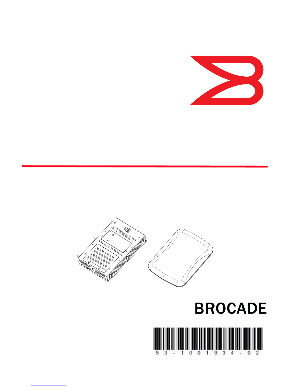
Brocade Mobility 650
Access Point
Installation Guide
Supporting software release 4.3.0.0 and later
®
53-1001934-02
Page 2

Copyright © 2011 Brocade Communications Systems, Inc. All Rights Reserved.
Brocade, the B-wing symbol, BigIron, DCX, Fabric OS, FastIron, IronPoint, IronShield, IronView, IronWare, JetCore,
NetIron, SecureIron, ServerIron, StorageX, and TurboIron are registered trademarks, and DCFM, Extraordinary
Networks, and SAN Health are trademarks of Brocade Communications Systems, Inc., in the United States and/or in
other countries. All other brands, products, or service names are or may be trademarks or service marks of, and are
used to identify, products or services of their respective owners.
Notice: This document is for informational purposes only and does not set forth any warranty, expressed or implied,
concerning any equipment, equipment feature, or service offered or to be offered by Brocade. Brocade reserves the
right to make changes to this document at any time, without notice, and assumes no responsibility for its use. This
informational document describes features that may not be currently available. Contact a Brocade sales office for
information on feature and product availability. Export of technical data contained in this document may require an
export license from the United States government.
The authors and Brocade Communications Systems, Inc. shall have no liability or responsibility to any person or entity
with respect to any loss, cost, liability, or damages arising from the information contained in this book or the computer
programs that accompany it.
Brocade Communications Systems, Incorporated
Corporate and Latin American Headquarters
Brocade Communications Systems, Inc.
130 Holger Way
San Jose, CA 95134
Tel: 1-408-333-8000
Fax: 1-408-333-8101
E-mail: [email protected]
European Headquarters
Brocade Communications Switzerland Sàrl
Centre Swissair
Tour B - 4ème étage
29, Route de l'Aéroport
Case Postale 105
CH-1215 Genève 15
Switzerland
Tel: +41 22 799 5640
Fax: +41 22 799 5641
E-mail: [email protected]
Document History
Asia-Pacific Headquarters
Brocade Communications Systems China HK, Ltd.
No. 1 Guanghua Road
Chao Yang District
Units 2718 and 2818
Beijing 100020, China
Tel: +8610 6588 8888
Fax: +8610 6588 9999
E-mail: [email protected]
Asia-Pacific Headquarters
Brocade Communications Systems Co., Ltd. (Shenzhen
WFOE)
Citic Plaza
No. 233 Tian He Road North
Unit 1308 – 13th Floor
Guangzhou, China
Tel: +8620 3891 2000
Fax: +8620 3891 2111
E-mail: [email protected]
Title Publication number Summary of changes Date
Brocade Mobility 650 Access Point
Installation Guide
Brocade Mobility 650 Access Point
Installation Guide
53-1001934-02 Updated WEEE logo April 2011
53-1001934-01 New document July 2010
Page 3

1 Introduction 1
Warnings . . . . . . . . . . . . . . . . . . . . . . . . . . . . . . . . . . . . . . . . . . . . . . . . . . . . . . . . . . . .1
Site preparation . . . . . . . . . . . . . . . . . . . . . . . . . . . . . . . . . . . . . . . . . . . . . . . . . . . . . .1
Brocade Mobility 650 package contents . . . . . . . . . . . . . . . . . . . . . . . . . . . . . . . . . .2
External antenna model package contents . . . . . . . . . . . . . . . . . . . . . . . . . . . . . . . . . . . . . . 2
Integrated antenna model package contents . . . . . . . . . . . . . . . . . . . . . . . . . . . . . . . . . . . . 2
Features . . . . . . . . . . . . . . . . . . . . . . . . . . . . . . . . . . . . . . . . . . . . . . . . . . . . . . . . . . . . . . . . . . 2
2 Hardware Installation 5
Installation instructions . . . . . . . . . . . . . . . . . . . . . . . . . . . . . . . . . . . . . . . . . . . . . . . .5
Precautions . . . . . . . . . . . . . . . . . . . . . . . . . . . . . . . . . . . . . . . . . . . . . . . . . . . . . . . . . .6
Access point placement . . . . . . . . . . . . . . . . . . . . . . . . . . . . . . . . . . . . . . . . . . . . . . . .6
Integrated antenna model wall mount instructions . . . . . . . . . . . . . . . . . . . . . . . . . .6
Wall mount hardware . . . . . . . . . . . . . . . . . . . . . . . . . . . . . . . . . . . . . . . . . . . . . . . . . . . . . . . 7
Wall mount procedure . . . . . . . . . . . . . . . . . . . . . . . . . . . . . . . . . . . . . . . . . . . . . . . . . . . . . . . 8
Integrated antenna model suspended ceiling T-bar mount instructions . . . . . . . . .9
Suspended ceiling mount procedure . . . . . . . . . . . . . . . . . . . . . . . . . . . . . . . . . . . . . . . . . . . 10
External antenna model wall mount instructions . . . . . . . . . . . . . . . . . . . . . . . . . . .11
Wall mount hardware . . . . . . . . . . . . . . . . . . . . . . . . . . . . . . . . . . . . . . . . . . . . . . . . . . . . . . . 11
Wall mount procedure . . . . . . . . . . . . . . . . . . . . . . . . . . . . . . . . . . . . . . . . . . . . . . . . . . . . . . . 12
External antenna model suspended ceiling tile (plenum) mount instructions . . . .13
Suspended ceiling mount hardware . . . . . . . . . . . . . . . . . . . . . . . . . . . . . . . . . . . . . . . . . . . . 14
Ceiling mount procedure . . . . . . . . . . . . . . . . . . . . . . . . . . . . . . . . . . . . . . . . . . . . . . . . . . . . . 14
Brocade Mobility 650 external antenna model antenna options . . . . . . . . . . . . . . .15
LED indicators . . . . . . . . . . . . . . . . . . . . . . . . . . . . . . . . . . . . . . . . . . . . . . . . . . . . . . .16
3 Specifications 17
Brocade Mobility 650 external antenna model electrical characteristics . . . . . . . .17
Brocade Mobility 650 external antenna model physical characteristics . . . . . . . . .17
Brocade Mobility 650 integrated antenna model electrical characteristics . . . . . .18
Brocade Mobility 650 integrated antenna model physical characteristics . . . . . . .18
Radio characteristics . . . . . . . . . . . . . . . . . . . . . . . . . . . . . . . . . . . . . . . . . . . . . . . . . .19
Console cable . . . . . . . . . . . . . . . . . . . . . . . . . . . . . . . . . . . . . . . . . . . . . . . . . . . . . . . .20
Brocade Mobility 650 Access Point Installation Guide iii
53-1001934-02
Page 4

4 Regulatory Compliance 21
Regulatory overview . . . . . . . . . . . . . . . . . . . . . . . . . . . . . . . . . . . . . . . . . . . . . . . . . . 21
Wireless device country approvals . . . . . . . . . . . . . . . . . . . . . . . . . . . . . . . . . . . . . . . 21
Country selection – note for AP & wireless controller . . . . . . . . . . . . . . . . . . . . . . . . . . . . . . 22
Frequency of operation – FCC and IC . . . . . . . . . . . . . . . . . . . . . . . . . . . . . . . . . . . . . . . . . . . 22
Health and safety recommendations . . . . . . . . . . . . . . . . . . . . . . . . . . . . . . . . . . . . . 23
Warnings for the use of wireless devices . . . . . . . . . . . . . . . . . . . . . . . . . . . . . . . . . . . . . . . . 23
Potentially hazardous atmospheres – fixed installations . . . . . . . . . . . . . . . . . . . . . . . . . . . 23
Safety in hospitals . . . . . . . . . . . . . . . . . . . . . . . . . . . . . . . . . . . . . . . . . . . . . . . . . . . . . . . . . . 23
RF exposure guidelines . . . . . . . . . . . . . . . . . . . . . . . . . . . . . . . . . . . . . . . . . . . . . . . . 24
Safety information . . . . . . . . . . . . . . . . . . . . . . . . . . . . . . . . . . . . . . . . . . . . . . . . . . . . . . . . . . 24
International . . . . . . . . . . . . . . . . . . . . . . . . . . . . . . . . . . . . . . . . . . . . . . . . . . . . . . . . 24
EU . . . . . . . . . . . . . . . . . . . . . . . . . . . . . . . . . . . . . . . . . . . . . . . . . . . . . . . . . . . . . . . . . 24
US and Canada . . . . . . . . . . . . . . . . . . . . . . . . . . . . . . . . . . . . . . . . . . . . . . . . . . . . . . 25
Power supply . . . . . . . . . . . . . . . . . . . . . . . . . . . . . . . . . . . . . . . . . . . . . . . . . . . . . . . . 25
Radio frequency interference requirements—FCC . . . . . . . . . . . . . . . . . . . . . . . . . . 25
Radio frequency interference requirements – Canada . . . . . . . . . . . . . . . . . . . . . . 26
Radio transmitters . . . . . . . . . . . . . . . . . . . . . . . . . . . . . . . . . . . . . . . . . . . . . . . . . . . . . . . . . . 26
CE Marking and European Economic Area (EEA) . . . . . . . . . . . . . . . . . . . . . . . . . . . 27
Statement of Compliance . . . . . . . . . . . . . . . . . . . . . . . . . . . . . . . . . . . . . . . . . . . . . . 27
TURKISH WEEE Statement of Compliance . . . . . . . . . . . . . . . . . . . . . . . . . . . . . . . . 27
Japan (VCCI) - voluntary control council for interference Class B ITE . . . . . . . . . . . 27
Korea warning statement for Class B ITE . . . . . . . . . . . . . . . . . . . . . . . . . . . . . . . . . 28
Other countries . . . . . . . . . . . . . . . . . . . . . . . . . . . . . . . . . . . . . . . . . . . . . . . . . . . . . . 28
Australia . . . . . . . . . . . . . . . . . . . . . . . . . . . . . . . . . . . . . . . . . . . . . . . . . . . . . . . . . . . . . . . . . . 28
Brazil . . . . . . . . . . . . . . . . . . . . . . . . . . . . . . . . . . . . . . . . . . . . . . . . . . . . . . . . . . . . . . . . . . . . . 28
Chile . . . . . . . . . . . . . . . . . . . . . . . . . . . . . . . . . . . . . . . . . . . . . . . . . . . . . . . . . . . . . . . . . . . . . 29
Mexico . . . . . . . . . . . . . . . . . . . . . . . . . . . . . . . . . . . . . . . . . . . . . . . . . . . . . . . . . . . . . . . . . . . 29
Taiwan . . . . . . . . . . . . . . . . . . . . . . . . . . . . . . . . . . . . . . . . . . . . . . . . . . . . . . . . . . . . . . . . . . . 29
Korea . . . . . . . . . . . . . . . . . . . . . . . . . . . . . . . . . . . . . . . . . . . . . . . . . . . . . . . . . . . . . . . . . . . . 30
5 Waste Electrical and Electronic Equipment (WEEE) 31
iv Brocade Mobility 650 Access Point Installation Guide
53-1001934-02
Page 5

About This Document
In this chapter
•Audience . . . . . . . . . . . . . . . . . . . . . . . . . . . . . . . . . . . . . . . . . . . . . . . . . . . . . . i
•Supported hardware and software . . . . . . . . . . . . . . . . . . . . . . . . . . . . . . . . . i
•Document conventions. . . . . . . . . . . . . . . . . . . . . . . . . . . . . . . . . . . . . . . . . . ii
•Contacting Brocade . . . . . . . . . . . . . . . . . . . . . . . . . . . . . . . . . . . . . . . . . . . . ii
•Warranty coverage . . . . . . . . . . . . . . . . . . . . . . . . . . . . . . . . . . . . . . . . . . . . . iii
Audience
This document is designed for system administrators with a working knowledge of
Layer 2 and Layer 3 switching and routing.
If you are using a Brocade Layer 3 Switch, you should be familiar with the following
protocols if applicable to your network – IP, RIP, OSPF, BGP, ISIS, IGMP, PIM, DVMRP,
and VRRP.
Supported hardware and software
The following hardware platforms are supported by this release of this guide:
• Brocade Mobility 650 Access Point
The following software versions are supported by this release of this guide:
• Software version 4.3.0.0 and later
Brocade Mobility 650 Access Point Installation Guide i
53-1001934-02
Page 6
Document conventions
This section describes text formatting conventions and important notice formats
used in this document.
Notes, cautions, and warnings
The following notices and statements are used in this manual. They are listed below
in order of increasing severity of potential hazards.
NOTE
A note provides a tip, guidance or advice, emphasizes important information, or
provides a reference to related information.
CAUTION
A Caution statement alerts you to situations that can be potentially
hazardous to you or cause damage to hardware, firmware, software, or
data.
DANGER
A Danger statement indicates conditions or situations that can be
potentially lethal or extremely hazardous to you. Safety labels are also
attached directly to products to warn of these conditions or situations.
Contacting Brocade
When contacting Brocade support, please provide the following information:
• Serial number of the unit
• Model number or product name
• Software version
ii Brocade Mobility 650 Access Point Installation Guide
53-1001934-02
Page 7

Customer Support Web Site
Brocade Support Central Web site, located at www.brocade.com/support provides
information and online assistance including developer tools, software downloads,
product manuals and online repair requests.
Downloads
http://www.brocade.com/support/
Manuals
http://www.brocade.com/support/
Because quality is our first concern at Brocade, we have made every effort to
ensure the accuracy and completeness of this document. However, if you find an
error or an omission, or you think that a topic needs further development, we want
to hear from you. Forward your feedback to: [email protected]
Provide the title and version number and as much detail as possible about your
comment, including the topic heading and page number and your suggestions for
improvement.
.
E-mail and telephone access
Go to http://www.brocade.com/services-support/index.page for email and
telephone contact information.
Warranty coverage
Contact Brocade Communications Systems using any of the methods listed above
for information about the standard and extended warranties.
Brocade Mobility 650 Access Point Installation Guide iii
53-1001934-02
Page 8

iv Brocade Mobility 650 Access Point Installation Guide
53-1001934-02
Page 9

Chapter
Introduction
The Brocade Mobility 650 Access Point links wireless 802.11a/b/g/n devices to the
controller, enabling growth of your wireless network with a cost-effective alternative
to standard access points. The Brocade Mobility 650 provides two placement
options: wall and ceiling. Wall mount slots fit onto two screws provided. Arrows on
the case guide placement of the screws. For placement above a suspended ceiling,
a safety wire tie point on the case provides for a loop of safety wire. The light pipe
fits through a hole in the ceiling tile to provide a view of the unit’s status lights.
The Brocade Mobility 650 receives all power and transfers data through the same
CAT-5 or better Ethernet cable. There is no additional power supply required. An
802.3af Ethernet switch or power injector is required.
Warnings
1
• Read all installation instructions and site survey reports, and verify correct
equipment installation before connecting the Brocade Mobility 650 Access
Point.
• Remove jewelry and watches before installing this equipment.
• Verify that the unit is grounded before connecting it to the power source.
• Verify that any device connected to this unit is properly wired and grounded.
• Verify there is adequate ventilation around the device, and that ambient
temperatures meet equipment operation specifications.
Site preparation
• Consult your site survey and network analysis reports to determine specific
equipment placement, power drops, and so on.
• Assign installation responsibility to the appropriate personnel.
• Identify and document where all installed components are located.
• Ensure adequate, dust-free ventilation to all installed equipment.
Brocade Mobility 650 Access Point Installation Guide 1
53-1001934-02
Page 10

1
Brocade Mobility 650 package contents
• Identify and prepare Ethernet and console port connections.
• Verify that cable lengths are within the maximum allowable distances for
optimal signal transmission.
Brocade Mobility 650 package contents
The Brocade Mobility 650 Access Point comes in four configurations, two Integrated
antenna models and two external antenna models. The contents of the package
differ between the integrated antenna model and the external antenna model.
External antenna model package contents
• Brocade Mobility 650 Access Point with external antenna connectors (Plenum
Rated)
• Two wall mount screws
• Two wall anchors
• Light pipe
• Badge for light pipe
• Brocade Mobility 650 Access Point Installation Guide (This Guide)
Integrated antenna model package contents
• Brocade Mobility 650 with integrated antennas
• Two wall mount screws
• Two wall anchors
• Brocade Mobility 650 Access Point Installation Guide (This Guide)
Features
• One RJ-45 connector
• LED indicators
• Safety wire tie point
• Slots for wall mounting
2 Brocade Mobility 650 Access Point Installation Guide
53-1001934-02
Page 11

Brocade Mobility 650 package contents
• Clips for mounting on a suspended ceiling T-bar
• Lock port for Kensington® style Security Lock
The Brocade Mobility 650 has one RJ-45 connector supporting an 10/100/1000
Ethernet port and requires 802.3af-compliant power from an external source.
NOTE
When operating in a Gigabit Ethernet environment CAT-5e or CAT-6 cable is required
for Gigabit operation.
The Brocade Mobility 650 comes in both single and dual radio versions both
supporting 802.11a/b/g/n.
The Brocade Mobility 650 Access Point contains runtime firmware which enables
the unit to boot after either a power up or a watchdog reset. The runtime firmware
on the access point and the firmware downloaded from the switch can be updated
via the Ethernet interface from the Wireless Controller.
1
Brocade Mobility 650 Access Point Installation Guide 3
53-1001934-02
Page 12

1
Brocade Mobility 650 package contents
4 Brocade Mobility 650 Access Point Installation Guide
53-1001934-02
Page 13

Chapter
Hardware Installation
Installation instructions
The Brocade Mobility 650 mounts either on a wall with wide-shoulder screws or on
a suspended ceiling T-bar. This unit is not designed for mounting on a desk.
To prepare for installation, perform the following steps:
1. Match the model number on the purchase order with the model numbers in the
packing list and on the case of the device shipped.
2. Verify that the contents of the box include the intended Brocade Mobility 650
Access Point and that the included hardware matches the package contents
detailed in “Brocade Mobility 650 package contents” on page 2.
Part number Description
2
BR-AP065060010 802.11a/b/g/n single radio integrated antenna configuration
BR-AP065066030 802.11a/b/g/n dual radio integrated antenna configuration
BR-AP065060020 802.11a/b/g/n single radio external antenna configuration
BR-AP065066040 802.11a/b/g/n dual radio external antenna configuration
3. Review site survey and network analysis reports to determine the location and
mounting position for the Brocade Mobility 650 Access Point.
4. Connect a CAT-5 or better Ethernet cable to a compatible 802.3af power source
and run the cable to the installation site. Ensure that there is sufficient slack
on the cable to perform the installation steps.
NOTE
When operating in a Gigabit Ethernet environment CAT-5e or CAT-6 cable is
required for Gigabit operation.
Brocade Mobility 650 Access Point Installation Guide 5
53-1001934-02
Page 14

2
Precautions
Precautions
Before installing a Brocade Mobility 650 Access Point, verify the following:
• Brocade recommends not to install the Brocade Mobility 650 in wet or dusty
areas.
• Verify the environment has a continuous temperature range between 0° C to
50° C.
Access point placement
For optimal performance, install the access point away from transformers,
heavy-duty motors, fluorescent lights, microwave ovens, refrigerators and other
industrial equipment. Signal loss can occur when metal, concrete, walls or floors
block transmission. Install the access point in an open area or add access points as
needed to improve coverage.
Antenna coverage is analogous to lighting. Users might find an area lit from far
away to be not bright enough. An area lit sharply might minimize coverage and
create dark areas. Uniform antenna placement in an area (like even placement of a
light bulb) provides even, efficient coverage.
Place the access point using the following guidelines:
• Install the access point at an ideal height of 10 feet from the ground.
• Orient the access point antennas vertically for best reception.
To maximize the access point’s radio coverage area, Brocade recommends
conducting a site survey to define and document radio interference obstacles
before installing the access point.
Integrated antenna model wall mount instructions
This mounting requires hanging the Brocade Mobility 650 Access Point along its
width or length using the two slots on the bottom of the unit. The Brocade Mobility
650 can be mounted onto any plaster, wood, or cement wall surface using the
provided wall anchors when necessary. The illustration shows a lengthwise mount.
6 Brocade Mobility 650 Access Point Installation Guide
53-1001934-02
Page 15

Integrated antenna model wall mount instructions
Wall mount hardware
• Two wide-shoulder Phillips pan head self-tapping screws
• Two wall anchors
• Security cable (optional)
NOTE
In the event that the original mounting screws are lost, the following screws can be
used instead: (ANSI Standard) #6-18 X 0.875in. Type A or AB Self-Tapping Screw, or
(ANSI Standard Metric) M3.5 X 0.6 X 20mm Type D Self-Tapping Screw.
2
Brocade Mobility 650 Access Point Installation Guide 7
53-1001934-02
Page 16
2
Integrated antenna model wall mount instructions
Wall mount procedure
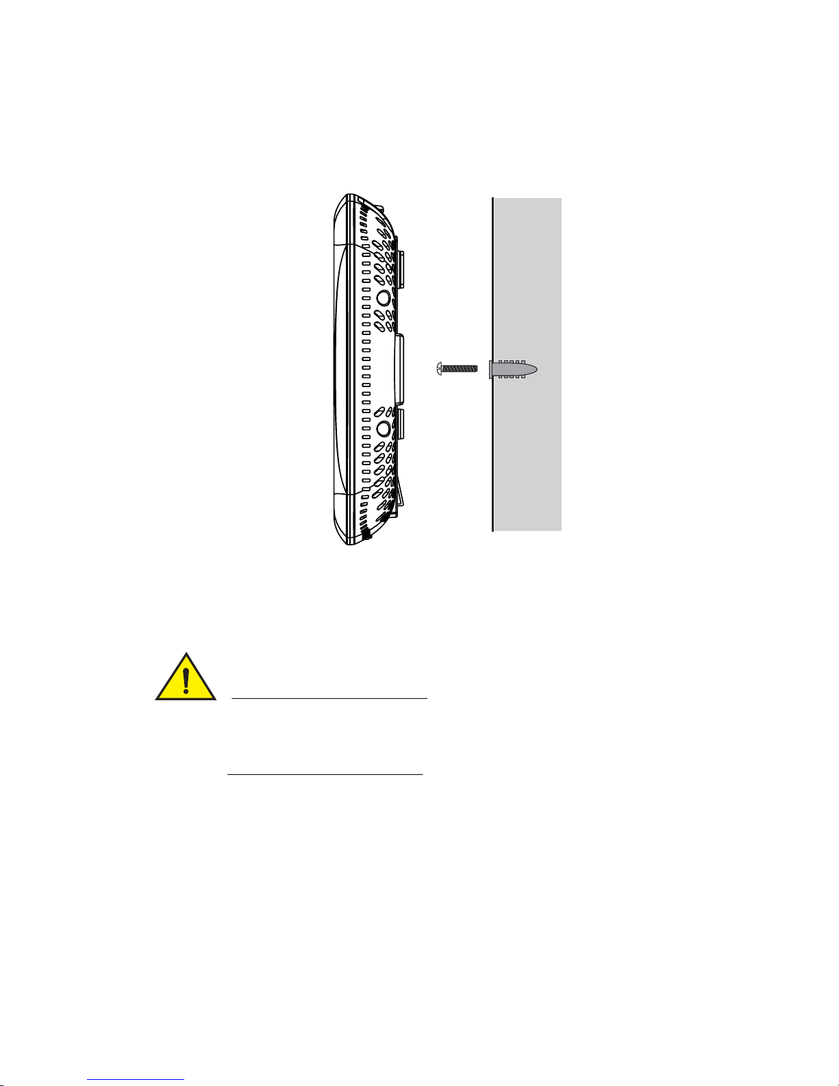
Integrated Antenna Wall Mount
1. Orient the case on the wall by its width or length.
CAUTION
To ensure proper operation of the Brocade Mobility 650 access point
ensure that the access point is mounted in the correct orientation with
the logo facing up.
2. Using the arrows on one edge of the case as guides, move the edge to the
midline of the mounting area and mark points on the midline for the screws
3. At each point, drill a hole in the wall, insert an anchor, screw into the anchor the
wall mounting screw and stop when there is 1mm between the screw head and
the wall
8 Brocade Mobility 650 Access Point Installation Guide
53-1001934-02
Page 17

Integrated antenna model suspended ceiling T-bar mount instructions
NOTE
When pre-drilling a hole the recommended hole size is 2.8mm (0.11in.) if the
screws are going directly into the wall and 6mm (0.23in.) if the provided wall
anchors are being used.
NOTE
If required, install and attach a security cable to the unit’s lock port.
4. Attach the Ethernet cable to the unit and to a switch with an
802.3af-compatible power source.
5. Place the middle of each of the case’s mount slots over the screw heads.
6. Slide the case down along the mounting surface to hang the mount slots on the
screw heads.
7. Verify the unit has power by observing that the LEDs are lit or flashing.
2
Integrated antenna model suspended ceiling T-bar
mount instructions
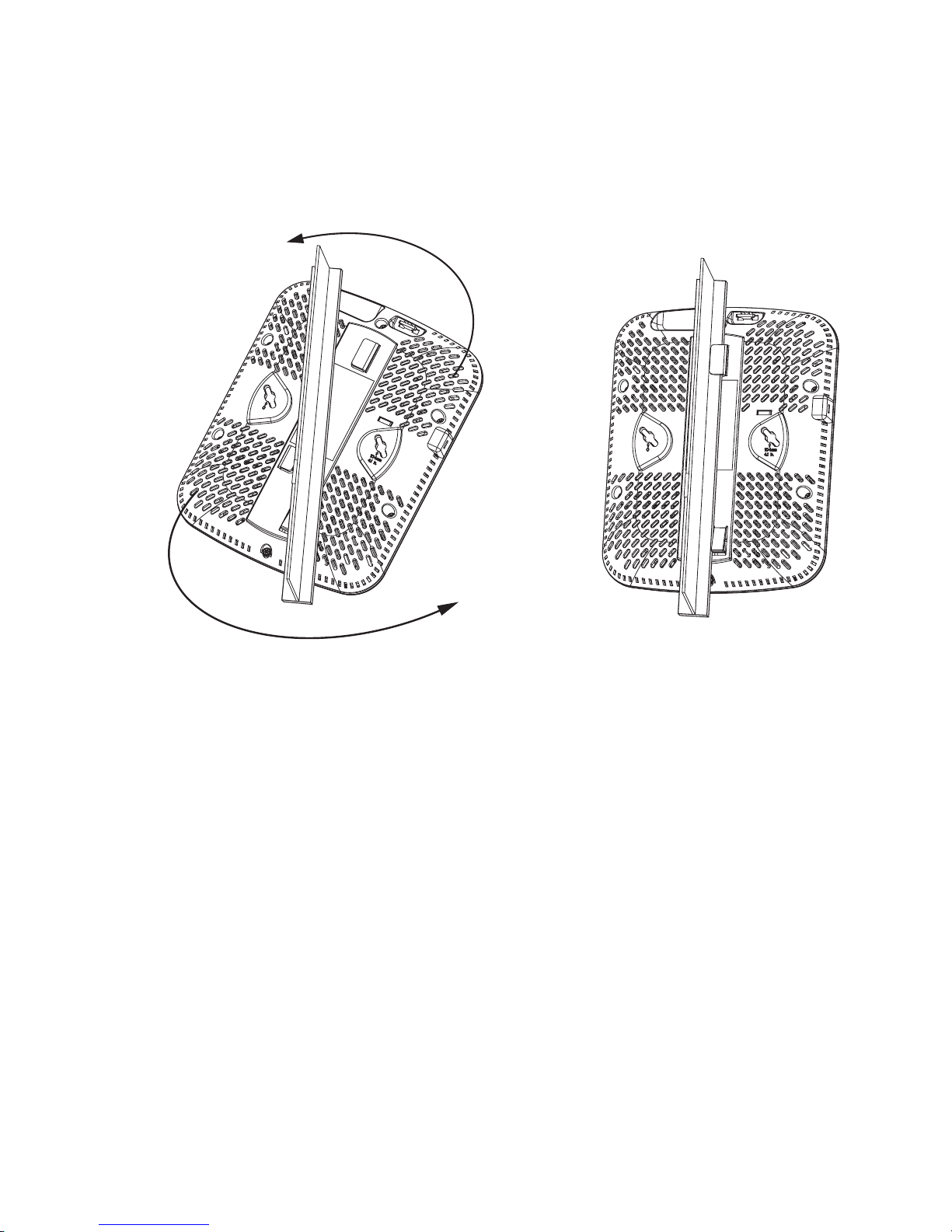
Ceiling mount requires holding the Brocade Mobility 650 up against a T-bar of a
suspended ceiling grid and twisting the case onto the T-bar.
Brocade Mobility 650 Access Point Installation Guide 9
53-1001934-02
Page 18
2
Integrated antenna model suspended ceiling T-bar mount instructions
Suspended ceiling mount procedure
1. If required, install and attach a security cable to the unit’s lock port.
2. Plug the Ethernet cable into the unit and to a switch with an
802.3af-compatible power source.
3. Face the bottom of the T-bar with the back of the case.
4. Orient the case by its length and the length of the T-bar.
5. Rotate the case in place 45 degrees clockwise, or about 10 o’clock.
6. Push the back of the case onto the bottom of the T-bar.
7. Rotate the case 45 degrees counter-clockwise. The clips click as they fasten to
the T-bar.
8. Verify the unit has power by observing the LEDs.
10 Brocade Mobility 650 Access Point Installation Guide
53-1001934-02
Page 19

External antenna model wall mount instructions
External antenna model wall mount instructions
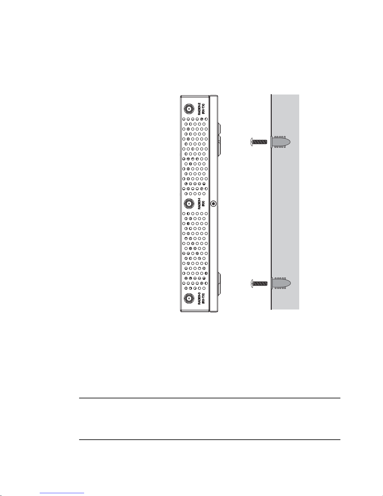
Wall mounting requires hanging the Brocade Mobility 650 along its width or length
using the pair of slots on the bottom of the unit. Brocade Mobility 650 can be
mounted onto any plaster, wood, or cement wall surface using the provided wall
anchors when necessary. The illustration shows a lengthwise mount
Wall mount hardware
• Two wide-shoulder Phillips pan head self-tapping screws
• Two wall anchors
• Safety wire (recommended) and security cable (optional)
NOTE
In the event that the original mounting screws are lost, the following screws can be
used instead: (ANSI Standard) #6-18 X 0.875in. Type A or AB Self-Tapping Screw, or
(ANSI Standard Metric) M3.5 X 0.6 X 20mm Type D Self-Tapping Screw.
2
Brocade Mobility 650 Access Point Installation Guide 11
53-1001934-02
Page 20
2
External antenna model wall mount instructions
Wall mount procedure
1. Orient the case on the wall by its width or length.
2. Using the arrows on one edge of the case as guides, move the edge to the
midline of the mounting area and mark points on the midline for the screws.
3. At each point, drill a hole in the wall, insert an anchor, screw into the anchor the
wall mounting screw and stop when there is 1mm between the screw head and
the wall.
NOTE
When pre-drilling a hole the recommended hole size is 2.8mm (0.11in.) if the
screws are going directly into the wall and 6mm (0.23in.) if the provided wall
anchors are being used.
12 Brocade Mobility 650 Access Point Installation Guide
53-1001934-02
Page 21

External antenna model suspended ceiling tile (plenum) mount instructions
4. If required, loop a safety wire, between 1.5mm (.06in.) and 2.5mm (.10in.) in
diameter, around the tie post and secure the loop.
5. If required, install and attach a security cable to the unit’s lock port.
6. Place the large corner of each of the case’s mount slots over the screw heads.
7. Slide the case down along the mounting surface to hang the mount slots on the
screw heads.
8. Attach appropriate antennas to the connectors.
9. Attach the Ethernet cable to the unit and to a switch with an 802.3af
compatible power source.
10. Verify the unit has power by observing that the LEDs are lit or flashing.
External antenna model suspended ceiling tile
2
(plenum) mount instructions
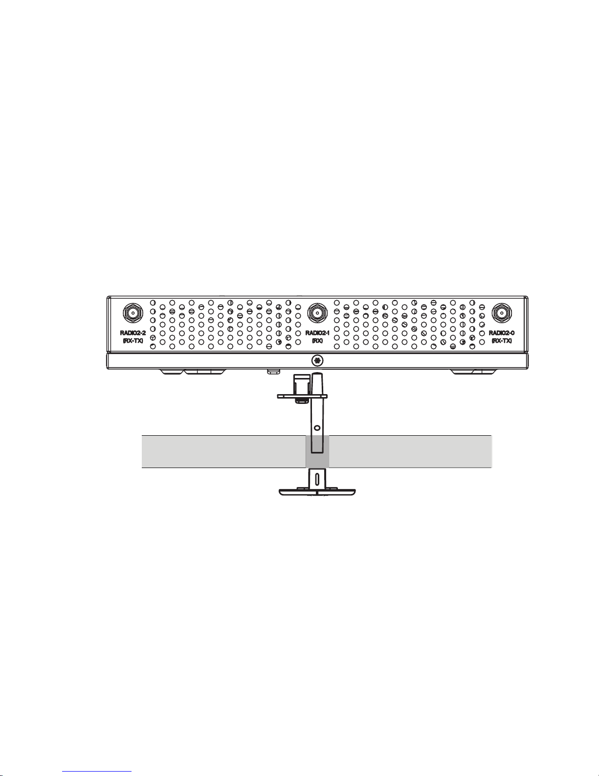
Ceiling mount requires placing the Brocade Mobility 650 above a suspended ceiling
and installing the provided light pipe for viewing the status lights of the unit.
NOTE
Notes or warnings about suspended ceiling mounts apply to all installations where
the unit is placed on suspended ceiling tile. The case has a safety wire tie point for
a standard safety wire.
CAUTION
Brocade does not recommend mounting the Brocade Mobility 650
directly to any suspended ceiling tile with a thickness less than
12.7mm (0.5in.) or a suspended ceiling tile with an unsupported span
greater than 660mm (26in.). Brocade strongly recommends fitting the
Brocade Mobility 650 with a safety wire suitable for the specific
installation. The safety wire should be a standard ceiling suspension
cable or equivalent steel wire between 1.59mm (.062in.) and 2.5mm
(.10in.) in diameter.
Brocade Mobility 650 Access Point Installation Guide 13
53-1001934-02
Page 22
2
External antenna model suspended ceiling tile (plenum) mount instructions
This placement requires installation of the provided light pipe for viewing the status
lights of the unit.
Suspended ceiling mount hardware
• Light pipe
• Badge for light pipe
• Safety wire (recommended) and security cable (optional)
Ceiling mount procedure
Light Pipe
Ceiling Tile
Badge
1. If possible, remove the ceiling tile from its frame and place it, finished side
down, on a work surface.
2. If required, install a safety wire, between 1.5mm (.06in.) and 2.5mm (.10in.) in
diameter, in the ceiling space.
3. If required, install and attach a security cable to the unit’s lock port.
4. Mark a point on the upper or unfinished side of the tile.
5. Push the light pipe through the tile at the mark and remove the light pipe. If
necessary, use a drill to make a hole in the tile.
6. Attach appropriate antennas to the connectors.
7. Snap the clips of the light pipe into the bottom of the case.
14 Brocade Mobility 650 Access Point Installation Guide
53-1001934-02
Page 23

Brocade Mobility 650 external antenna model antenna options
8. Fit the light pipe into hole in the tile from its unfinished side.
9. Attach any safety wire to the safety wire tie point or security cable to the unit’s
lock port.
10. Bring the tile into the ceiling space.
11. Plug the Ethernet cable into the unit and to a switch with an
802.3af-compatible power source.
12. Verify the unit has power by observing the LEDs.
13. Place the ceiling tile back in its frame.
14. Snap the badge onto the light pipe from the finished side of the tile.
Brocade Mobility 650 external antenna model
2
antenna options
Brocade supports two antenna suites for Brocade Mobility 650 External Antenna
models. One antenna suite supporting the 2.4 GHz band and another antenna suite
supporting the 5 GHz band. Select an antenna model best suited to the intended
operational environment of your access point.
On single radio versions, the R-SMA connectors can support both bands and should
be connected to a R-SMA dual-band antenna or an appropriate single band
antenna.
The 2.4 GHz antenna suite includes the following models:
Part Number Antenna Type
ML-2499-HPA3-01R Omni-Directional Antenna
ML-2499-SD3-01R Patch Antenna
ML-2452-APA2-01 Dual-Band
ML-2452-PNA5-01R Panel Antenna
ML-2452-PTA3M3-036 Omni-Directional Antenna
Brocade Mobility 650 Access Point Installation Guide 15
53-1001934-02
Page 24

2
LED indicators
The 5 GHz antenna suite includes the following models:
Part Number Antenna Type
ML-5299-HPA1-01R Omni-Directional Antenna
ML-5299-PTA1-01R Patch Antenna
ML-2452-APA2-01 Dual-Band
ML-2452-PNA5-01R Panel Antenna
ML-2452-PTA3M3-036 Omni-Directional Antenna
For detailed specifications on the antennas available to the Mobility 650, refer to
the Enterprise Wireless LAN Antenna Specification Guide available at
http://www.brocade.com/support/
.
LED indicators
Both the Integrated Antenna model and the External Antenna model have LED
activity indicators on the front of the case for use with wall mount. With the External
Antenna model unit mounted above a ceiling, LEDs are at the center of an oval
badge on the ceiling; a light pipe enables viewing the back LEDs through the ceiling
tile.
The LEDs provide a status display indicating error conditions, transmission, and
network activity for the 5 GHz 802.11a/n (amber) radio or the 2.4 GHz
802.11b/g/n (green) radio.
Task 5 GHz Activity LED (Amber) 2.4 GHz Activity LED (Green)
Unadopted Off Blinking at 5Hz
Normal
Operation
If this radio band is enabled:
Blink at 5 second interval
If this radio band is disabled:
Off
If there is activity on this band:
Blink at a 1Hz
If this radio band is enabled:
Blink at 5 second interval
If this radio band is disabled:
Off
If there is activity on this band:
Blink at a 1Hz
Firmware
Update
Locate AP
Mode
16 Brocade Mobility 650 Access Point Installation Guide
On Off
Blink at 5Hz
(Out of Phase with Activity LED)
Blink at 5Hz
(Out of Phase with Activity LED)
53-1001934-02
Page 25

Chapter
Specifications
3
Brocade Mobility 650 external antenna model
electrical characteristics
A Brocade Mobility 650 external antenna model access point has the following
electrical characteristics:
Operating current & voltage
180ma- 270ma @ 48VDC
Brocade Mobility 650 external antenna model physical
characteristics
A Brocade Mobility 650 external antenna model access point has the following
physical characteristics:
Dimensions
Housing
Weight
Operating temperature
Storage temperature
Operating humidity
Storage humidity
Operating altitude (max)
Storage altitude (max)
Electrostatic discharge
8.50 in. Depth x 5.5 in. Width x 1.5 in. Height
21.59 cm Depth x 13.97 cm Width x 3.81 cm Height
Metal
2.5 lbs / 1.13 kg
32°F to 122°F/0°C to 50°C
-40°F to 158°F/-40°C to 70°C
5 to 95% Relative Humidity non-condensing
85% Relative Humidity non-condensing
8,000 ft @ 28C
30,000 ft @ 12C
+/-15kV Air and +/-8kV Contact @ 50% Relative Humidity
Brocade Mobility 650 Access Point Installation Guide 17
53-1001934-02
Page 26

3
Brocade Mobility 650 integrated antenna model electrical characteristics
Brocade Mobility 650 integrated antenna model
electrical characteristics
A Brocade Mobility 650 Integrated model access point has the following electrical
characteristics:
Operating Current &
voltage
180ma- 270ma @ 48VDC
Brocade Mobility 650 integrated antenna model
physical characteristics
A Brocade Mobility 650 Integrated Antenna model access point has the following
physical characteristics:
Dimensions
Housing
Weight
Operating temperature
Storage temperature
9.50 in. Depth x 7.5 in. Width x 1.9 in. Height
24.13 cm Depth x 19.05 cm Width x 4.83 cm Height
Plastic
2.0 lbs / 0.91 kg
32°F to 122°F/0°C to 50°C
-40°F to 158°F/-40°C to 70°C
Operating humidity
Storage humidity
Operating altitude
(max)
Storage altitude
(max)
Electrostatic discharge
18 Brocade Mobility 650 Access Point Installation Guide
5 to 95% Relative Humidity non-condensing
85% Relative Humidity non-condensing
8,000 ft @ 28C
30,000 ft @ 12C
+/-15kV Air and +/-8kV Contact @ 50% Relative Humidity
53-1001934-02
Page 27

Radio characteristics
Radio characteristics
The Brocade Mobility 650 access points have the following radio characteristics:
3
Operating channels
Data rates supported
Wireless medium
Network standards
Maximum available
transmit power
All channels from 4920 MHz to 5825 MHz except channel 52 -64
Channels 1-13 (2412-2472 MHz)
Channel 14 (2484 MHz) Japan only
Actual operating frequencies depend on regulatory approval for the
country of use.
802.11g: 1,2,5.5,11,6,9,12,18,24,36,48, and 54Mbps
802.11a: 6,9,12,18,24,36,48, and 54Mbps
802.11n: MCS 0-15 up to 300Mbps
Direct Sequence Spread Spectrum (DSSS),
Orthogonal Frequency Division Multiplexing (OFDM)
Spatial multiplexing (MIMO)
802.11a, 802.11b, 802.11g, 802.3, 802.11n (Draft 2.0)
Maximum available conducted transmit power per chain:
2.4 GHz: 21dBm
Maximum available conducted transmit power all chains:
2.4 GHz: 24dBm
Maximum available conducted transmit power per chain:
5 GHz: 19dBm
Maximum available conducted transmit power all chains:
5 GHz: 22dBm
Transmit power
adjustment
Antenna configuration
Brocade Mobility 650 Access Point Installation Guide 19
53-1001934-02
1dB increments
2x3 MIMO (transmit on two and receive on all three
antennas)
Page 28
3
Console cable
Console cable
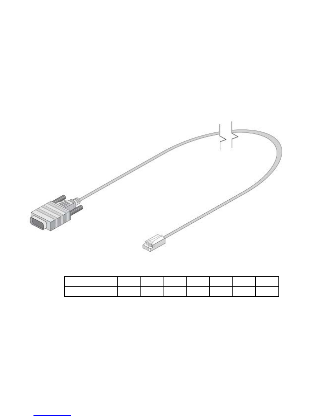
A console cable (pictured below) is used to connect the Brocade Brocade Mobility
650 access point ’s serial port to an RS-232 (DB-9) serial port on a separate
computer.
The pinout for the RJ-45 to DB9 cable is shown in the following table.
RJ-45 1 2 3 4,5 6 7 8
DB9 8 6 2 5 3 4 7
20 Brocade Mobility 650 Access Point Installation Guide
53-1001934-02
Page 29

Chapter
Regulatory Compliance
Regulatory overview
All Brocade devices are designed to be compliant with rules and regulations in
locations they are sold and will be labeled as required. Any changes or
modifications to Brocade equipment, not expressly approved by Brocade, could void
the user’s authority to operate the equipment.
Brocade access points must be professionally installed and configured so that the
Radio Frequency Output Power will not exceed the maximum allowable limit for the
country of operation.
Antennas: Use only the supplied or an approved replacement antenna.
Unauthorized antennas, modifications, or attachments could cause damage and
may violate regulations. Use of and unapproved antenna is illegal under FCC
regulations subjecting the end user to fines and equiment sesure.
4
Radio modules
This access point contains approved radio module(s) MB82. These module(s) are
identified below.
MB82 – a DFS Master WLAN 802.11 abgn MIMO 2x3 radio module.
Wireless device country approvals
Regulatory markings, subject to certification, are applied to the device signifying the
radio(s) is/are approved for use in the following countries: United States, Canada,
Japan, China, S. Korea, Australia, and Europe.
Please refer to the Symbol Declaration of Conformity (DoC) for details of other
country markings. This is available at http://www2.symbol.com/doc/
.
Brocade Mobility 650 Access Point Installation Guide 21
53-1001934-02
Page 30

4
Wireless device country approvals
NOTE
Note: For 2.4GHz or 5GHz Products: Europe includes, Austria, Belgium, Bulgaria,
Czech Republic, Cyprus, Denmark, Estonia, Finland, France, Germany, Greece,
Hungary, Iceland, Ireland, Italy, Latvia, Liechtenstein, Lithuania, Luxembourg, Malta,
Netherlands, Norway, Poland, Portugal, Romania, Slovak Republic, Slovenia, Spain,
Sweden, Switzerland and the United Kingdom.
Operation of the device without regulatory approval is illegal.
Country selection – note for AP & wireless controller
Select only the country in which you are using the device. Any other selection will
make the operation of this device illegal. The US version of the access point will
only have US listed in the country selection table. The US version will be sold / used
in the US protectorates: American Samoa, Guam, Puerto Rico, US Virgin Islands.
Frequency of operation – FCC and IC
5 GHz only
The use on UNII (Unlicensed National Information Infrastructure) Band 1
5150-5250 MHz and Band 3 5470 - 5725 MHz is restricted to indoor use only, any
other use will make the operation of this device illegal.
Devices using the 5470 – 5725 MHz band shall not be capable of transmitting in
the band 5600 - 5650 MHz in the US, this “Notched” band has been disabled in the
US version of the access point.
The available channels for 802.11 b/g operation in the US are Channels 1 to 11.
The range of channels is limited by firmware.
2.4 GHz only
The available channels for 802.11 b/g operation in the US are Channels 1 to 11.
The range of channels is limited by firmware.
22 Brocade Mobility 650 Access Point Installation Guide
53-1001934-02
Page 31

Health and safety recommendations
Health and safety recommendations
Warnings for the use of wireless devices
Please observe all warning notices with regard to the usage of wireless devices
Potentially hazardous atmospheres – fixed installations
You are reminded of the need to observe restrictions on the use of radio devices in
fuel depots, chemical plants etc. and areas where the air contains chemicals or
particles (such as grain, dust, or metal powders).
Safety in hospitals
4
Wireless devices transmit radio frequency energy and may affect medical
electrical equipment. When installed adjacent to other equipment, it is
advised to verify that the adjacent equipment is not adversely affected.
Pacemakers
Pacemaker manufacturers recommended that a minimum of 15cm (6 inches) be
maintained between a handheld wireless device and a pacemaker to avoid
potential interference with the pacemaker. These recommendations are consistent
with independent research and recommendations by Wireless Technology
Research.
Persons with Pacemakers:
• Should ALWAYS keep the device more than 15cm (6 inches) from their
pacemaker when turned ON.
• Should not carry the device in a breast pocket.
• Should use the ear furthest from the pacemaker to minimize the potential for
interference.
• If you have any reason to suspect that interference is taking place, turn OFF
your device.
Brocade Mobility 650 Access Point Installation Guide 23
53-1001934-02
Page 32

4
RF exposure guidelines
Other medical devices
Please consult your physician or the manufacturer of the medical device, to
determine if the operation of your wireless product may interfere with the medical
device.
RF exposure guidelines
Safety information
Reducing RF exposure—use properly
Only operate the device in accordance with the instructions supplied.
International
The device complies with internationally recognized standards covering human
exposure to electromagnetic fields from radio devices. For information on
“International” human exposure to eletromagnic fields refer to the Please refer to
the Declaration of Conformity (DoC). This is available at
http://www2.symbol.com/doc/
EU
Remote and standalone antenna configurations
To comply with EU RF exposure requirements, antennas that are mounted
externally at remote locations or operating near users at stand-alone desktop of
similar configurations must operate with a minimum separation distance of 20 cm
from all persons.
.
24 Brocade Mobility 650 Access Point Installation Guide
53-1001934-02
Page 33

US and Canada
US and Canada
Co-located statement
To comply with FCC RF exposure compliance requirement, the antennas used for
this transmitter must not be co-located or operating in conjunction with any other
transmitter/antenna except those already approved in this filling.
Remote and standalone antenna configurations
To comply with FCC RF exposure requirements, antennas that are mounted
externally at remote locations or operating near users at stand-alone desktop of
similar configurations must operate with a minimum separation distance of 20 cm
from all persons.
4
Power supply
This device is powered from a 802.3af compliant power source which is UL
approved and certified by the appropriate agencies.
Radio frequency interference requirements—FCC
This equipment has been tested and found to comply with the
limits for a Class B digital device, pursuant to Part 15 of the FCC
rules. These limits are designed to provide reasonable protection
against harmful interference in a residential installation. This
equipment generates, uses and can radiate radio frequency energy
and, if not installed and used in accordance with the instructions, may cause
harmful interference to radio communications. However there is no guarantee that
interference will not occur in a particular installation. If this equipment does cause
harmful interference to radio or television reception, which can be determined by
turning the equipment off and on, the user is encouraged to try to correct the
interference by one or more of the following measures:
• Reorient or relocate the receiving antenna
• Increase the separation between the equipment and receiver
Brocade Mobility 650 Access Point Installation Guide 25
53-1001934-02
Page 34

4
Radio frequency interference requirements – Canada
• Connect the equipment into an outlet on a circuit different from that to which
the receiver is connected
• Consult the dealer or an experienced radio/TV technician for help
Radio transmitters (Part 15)
This device complies with Part 15 of the FCC Rules. Operation is subject to the
following two conditions: (1) this device may not cause harmful interference, and
(2) this device must accept any interference received, including interference that
may cause undesired operation.
Restricted Band 5.60 – 5.65 GHz
Radio frequency interference requirements – Canada
This Class B digital apparatus complies with Canadian ICES-003.
Cet appareil numérique de la classe B est conforme à la norme NMB-003 du
Canada.
Radio transmitters
For RLAN Devices:
The use of 5 GHz RLAN’s, for use in Canada, have the following restrictions:
• Restricted Band 5.60 – 5.65 GHz
This device complies with RSS 210 of Industry & Science Canada. Operation is
subject to the following two conditions: (1) this device may not cause harmful
interference and (2) this device must accept any interference received, including
interference that may cause undesired operation.
Label Marking: The Term "IC:" before the radio certification only signifies that
Industry Canada technical specifications were met.
26 Brocade Mobility 650 Access Point Installation Guide
53-1001934-02
Page 35

CE Marking and European Economic Area (EEA)
CE Marking and European Economic Area (EEA)
The use of 2.4 GHz RLAN’s, for use through the EEA, have the following
restrictions:
• Maximum radiated transmit power of 100 mW EIRP in the frequency range
2.400 -2.4835 GHz.
• France, outside usage is restricted to 2.4 – 2.454 GHz.
• Italy requires a user license for outside usage.
Statement of Compliance
Brocade hereby, declares that this device is in compliance with the essential
requirements and other relevant provisions of Directive 1999/5/EC. A Declaration
of Conformity may be obtained from http://www2.symbol.com/doc/
.
4
TURKISH WEEE Statement of Compliance
EEE Yönetmeli?ine Uygundur
Japan (VCCI) - voluntary control council for interference
Class B ITE
この装置は、情報処理装置等電波障害自主規制協議会 (VCCI)の基準に基づくク
ラス B 情報技術装置です。この装置は、家庭環境で使用することを目的としています
が、この装置がラジオやテレビジョン受信機に近接して使用されると、受信障害を引
き起こすことがあります。 取扱説明書に従って正しい取り扱いをして下さい。
This is a Class B product based on the standard of the Voluntary Control Council for
Interference from Information Technology Equipment (VCCI). If this is used near a
radio or television receiver in a domestic environment, it may cause radio
interference. Install and use the equipment according to the instruction manual.
Brocade Mobility 650 Access Point Installation Guide 27
53-1001934-02
Page 36
4
Korea warning statement for Class B ITE
Korea warning statement for Class B ITE
기 종 별 사 용 자 안 내 문
B급 기기
( 가정용 방송통신기기 )
Class B (Broadcasting Communication
Device for Home Use)
Other countries
Australia
Use of 5 GHz RLAN’s in Australia is restricted in the following band 5.50 – 5.65
GHz.
Brazil
Regulatory declarations for AP-650 - BRAZIL
이 기기는 가정용 (B 급 ) 으로 전자파적합등록을
한 기기로서 주로 가정에서 사용하는 것을 목적
으로 하며 , 모든 지역에서 사용할 수 있습니다 .
This device obtained EMC registration mainly for home use (Class
B) and may be used in all areas.
Note: The certification mark applied to the AP-650 is for Restrict Radiation
Equipment. This equipment operates on a secondary basis and does not have the
right for protection against harmful interference from other users including same
equipment types. Also this equipment must not cause interference to systems
operating on primary basis.
For more information consult the website http://www.anatel.gov.br
Declarações Regulamentares para AP-650 - Brasil
Nota: "A marca de certificação se aplica ao Transceptor, modelo AP-650. Este
equipamento opera em caráter secundário, isto é, não tem direito a proteção
contra interferência prejudicial, mesmo de estações do mesmo tipo, e não pode
causar interferência a sistemas operando em caráter primário.”
Para maiores informações sobre ANATEL consulte o site: http://www.anatel.gov.br
28 Brocade Mobility 650 Access Point Installation Guide
53-1001934-02
Page 37

Other countries
Chile
“Este equipo cumple con la Resolución No 403 de 2008, de la Subsecretaria de
telecomunicaciones, relativa a radiaciones electromagnéticas.”.
"This device complies with the Resolution Not 403 of 2008, of the Undersecretary
of telecommunications, relating to electromagnetic radiation.”
Mexico
Restrict Frequency Range to: 2.450 – 2.4835 GHz.
Taiwan
NOTICE!
4
According to: Administrative Regulations on Low Power Radio Waves Radiated
Devices
Article 12
Without permission granted by the DGT, any company, enterprise, or user is not
allowed to change frequency, enhance transmitting power or alter original
characteristic as well as performance to an approved low power radio-frequency
devices.
Article 14
The low power radio-frequency devices shall not influence aircraft security and
interfere legal communications; If found, the user shall cease operating
immediately until no interference is achieved.
The said legal communications means radio communications is operated in
compliance with the Telecommunications Act.
Brocade Mobility 650 Access Point Installation Guide 29
53-1001934-02
Page 38
4
Other countries
The low power radio-frequency devices must be susceptible with the
interference from legal communications or ISM radio wave radiated devices
臺灣
低功率電波輻射性電機管理辦法
第十二條
經型式認證合格之低功率射頻電機,非經許可,公司、商號或使用者均不得擅自
變更頻率、加大功率或變更原設計之特性及功能。
第十四條
低功率射頻電機之使用不得影響飛航安全及干擾合法通信;經發現有干擾現象
時,應立 ? 停用,? 改善至無干擾時方得繼續使用。
前項合法通信,指依電信規定作業之無線電通信。
低功率射頻電機須忍受合法通信或工業、科學及醫療用電波輻射性電機設備之干
擾。
.
Wireless device operate in the frequency band of 5.25-5.35 GHz, limited for Indoor
use only.
在 5.25-5.35 赫頻帶內操作之無線資訊傳輸設備,限於室內使用。
Korea
For a radio equipment using 2400~2483.5MHz or 5725~5825MHz, the following
two expression should be displayed:
1. “This radio equipment can be interfered during operation.”
당해 무선설비는 운용 중 전파혼신 가능성이 있음
2. “This radio equipment cannot provide a service relevant to the human life
safety, as it can be crossed” through the user manual etc.
당해 무선설비 는전파혼 신 가능성이 있으므로 인명안전과 관련된 서비스는 할 수 없습니다
30 Brocade Mobility 650 Access Point Installation Guide
53-1001934-02
Page 39
Chapter
Waste Electrical and Electronic Equipment
(WEEE)
For information on WEEE, please go to:
http://www.brocade.com/sites/dotcom/company/
corporate-responsibility/corporate-citizenship/product-recycling/
weee.page.
5
Brocade Mobility 650 Access Point Installation Guide 31
53-1001934-02
Page 40

 Loading...