

Brocade Communications Systems Mobility 300 Quick Installation Manual
Introduction
The Brocade Mobility 300, a component of the Brocade Wireless Controller
System, links wireless 802.11a/b/g devices to the controller, enabling growth of
your wireless network with a cost-effective alternative to standard access points.
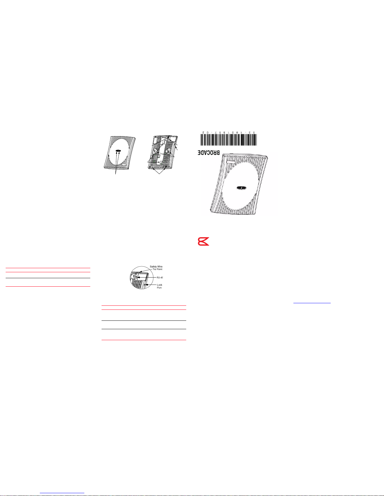
The Mobility 300 provides two placement options: wall and ceiling. Wall mount
slots fit onto two screws provided. Arrows on the case guide placement of the
screws. Clips on the back of the case fit onto a suspended ceiling T-bar.
The Mobility 300 receives all power and transfers data through the same CAT-5
cable. There is no additional power supply required.
Technical specifications
Dimensions & weight
Features
• One RJ-45 connector
•LED indicators
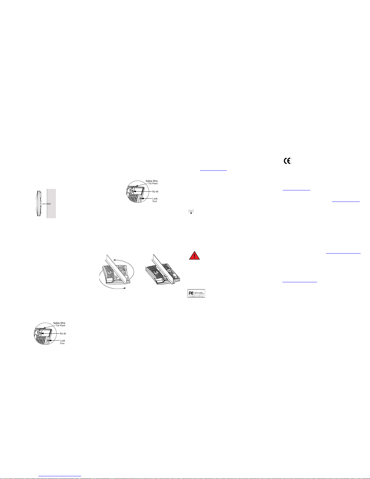
• Safety wire tie point
•Laptop-style lock port
• Slots for wall mounting
• Clips for mounting on a suspended ceiling T-bar
The Mobility 300 has one RJ-45 connector supporting an 10/100 Ethernet port
and requires 802.3af-compliant power from an external source.
The Mobility 300 comprises two 802.11 radios: an 802.11b/g radio operating in
the 2.4 to 2.5GHz band and an 802.11a radio operating in the 4.9 to 5.875GHz
band.
Motherboard firmware enables the unit to boot after either a power up or a
watchdog reset. After self-boot, the motherboard sends an “I am alive” message
into the network to be adopted and loaded with the actual runtime code. The
boot firmware on the motherboard and the firmware downloaded from the
controller can be updated using the Ethernet interface from the Wireless
Controller.
Operating voltage 48VDC typical; 36-57VDC range
Operating current 100mA to 165mA
Peak current 250mA
Operating temperature 0°C to 40°C (32°F to 104°F)
Operating humidity 5% to 95% non-condensing
Operating altitude (max ) 2438m (8,000ft.)
Storage temperature -40°C to 70°C (-40°F to 158°F)
Storage humidity 85%
Storage altitude (max.) 4572m (15,000ft.)
Drop 910mm (36in.) to concrete
Electrostatic discharge +/-15kV air; +/-8kV contact; +/-2kV
pin
Length 241mm (9.5in.)
Width 178mm (7.0in.)
Height 51mm (2.0in.)
Weight 0.45kg (1.0lbs)
LEDs
Wall
Mount
Slot
Lock
Port
RJ-45
Safety
Wire
Tie
Point
Alignment Arrows
T-bar
Mount
Clip
Service information
Before using the unit, it must be configured to operate in the facility’s network
and run your applications. If you have a problem running your unit or using your
equipment, contact your facility’s Technical or Systems Support. If there is a
problem with the equipment, they will contact the Brocade Support Central.
Brocade Communications Systems, Incorporated
Corporate and Latin American Headquarters
Brocade Communications Systems, Inc.
130 Holger Way
San Jose, CA 95134
Tel: 1-408-333-8000 Fax: 1-408-333-8101
E-mail: info@brocade.com
European Headquarters
Brocade Communications Switzerland Sàrl
Centre Swissair
Tour B - 4ème étage
29, Route de l'Aéroport
Case Postale 105
CH-1215 Genève 15
Switzerland
Tel: +41 22 799 5640 Fax: +41 22 799 5641
E-mail: emea-info@brocade.com
Asia-Pacific Headquarters
Brocade Communications Systems China HK, Ltd.
No. 1 Guanghua Road
Chao Yang District
Units 2718 and 2818
Beijing 100020, China
Tel: +8610 6588 8888 Fax: +8610 6588 9999
E-mail: china-info@brocade.com
Brocade Mobility 300 Access Point
Internal Antenna Model
Quick Installation Guide
53-1001557-02
®
Radio characteristics
The Mobility 300 is an IEEE 802.11-compliant device with one 802.11a radio
and one 802.11b/g radio. The following table lists radio characteristics for each
radio’s compliance. The three supported 802.11g modes are simultaneous CCK
and OFDM, CCK only, or OFDM only.
Mobility 300 package contents
• Mobility 300
•Two screws
• Two wall anchors
• Quick Installation Guide
Description
The Mobility 300 (Part Number BR-AP300-5110) is an IEEE 802.11-compliant
device. The unit supports external antennas, listed under Supported Antennas,
and it requires power from any UL-listed, 802.3af-compatible Power Over
Ethernet (PoE) switch or power injector.
Lock port
The lock port, compatible with laptop-style security cables, is on the side of the
case.
LED indicators
The unit has LED activity indicators on the front of the case provide a status
display indicating error conditions, transmission, and network activity for the
802.11a (amber) radio or the 802.11b/g (green) radio.
Brocade, the B-wing symbol, BigIron, DCX, Fabric OS, FastIron, IronPoint,
IronShield, IronView, IronWare, JetCore, NetIron, SecureIron, ServerIron,
StorageX, and TurboIron are registered trademarks, and DCFM, Extraordinary
Networks, and SAN Health are trademarks of Brocade Communications
Systems, Inc., in the United States and/or in other countries. All other brands,
products, or service names are or may be trademarks or service marks of, and
are used to identify, products or services of their respective owners.
Notice: This document is for informational purposes only and does not set forth
any warranty, expressed or implied, concerning any equipment, equipment
feature, or service offered or to be offered by Brocade. Brocade reserves the
right to make changes to this document at any time, without notice, and
assumes no responsibility for its use. This informational document describes
features that may not be currently available. Contact a Brocade sales office for
information on feature and product availability. Export of technical data
contained in this document may require an export license from the United States
government.
The authors and Brocade Communications Systems, Inc. shall have no liability or
responsibility to any person or entity with respect to any loss, cost, liability, or
damages arising from the information contained in this book or the computer
programs that accompany it.
The product described by this document may contain “open source” software
covered by the GNU General Public License or other open source license
agreements. To find out which open source software is included in Brocade
products, view the licensing terms applicable to the open source software, and
obtain a copy of the programming source code, please visit
http://www.brocade.com/support/
.
Device Mbps data rate support Utilizing diversity GHz
802.11a 6, 9, 12, 18, 24, 36, 48, 54
OFDM
Tran smit a nd
receive
4.9 to 5.875 range
802.11b/g 1, 2, 5.5, 11 CCK
6, 9, 12, 18, 24, 36, 48, 54
OFDM
Tran smit a nd
receive
2.4 to 2.5 ISM
range
Task 802.11a activity LED amber 802.11b/g activity LED green
Booting The amber LED flashes three times per
second until firmware is loaded. During
boot, 802.11a mobiles cannot
associate.
The green LED flashes three times
per second until firmware is loaded.
During boot, 802.11b/g mobiles
cannot associate.
Normal After adoption, the amber LED is
steady or flashes with 802.11a radio
traffic.
After adoption, the green LED is
steady or flashes with 802.11b/g
radio traffic.
Error The amber LED flashes once per
second if an error prevents the
802.11a radio from operating
normally.
The green LED flashes once per
second if an error prevents the
802.11b/g radio from operating
normally.
(4) (6) (1) (2)
(3) (5)
Installation instructions
The Mobility 300 mounts either on a wall with wide-shoulder screws or on a
suspended ceiling T-bar. This unit is not designed for mounting on a desk.
To prepare for installation, perform the following steps:
1. Match the model number on the purchase order with the model numbers in
the packing list and on the case of the device shipped.
2. Verify that the contents of the box include the intended Mobility 300 and
that the included hardware matches the package contents on page 4.
3. Review site survey and network analysis reports to determine the location
and mounting position for the Mobility 300.
4. Connect a CAT-5 cable to a compatible 802.3af power source and run the
cable to the installation site. Ensure that there is sufficient slack on the
cable to perform the installation steps.
Wall mount
This mounting requires hanging the Mobility 300 along its width or length using
the two slots on the bottom of the unit. The IP 350 can be mounted onto any
plaster, wood, or cement wall surface using the provided wall anchors when
necessary. The illustration shows a lengthwise mount.
Wall mount hardware
• Two wide-shoulder Phillips pan head self-tapping screws
• Two wall anchors
• Safety wire (recommended) and security cable (optional)
• In the event that the original mounting screws are lost, the following screws
can be used instead: (ANSI Standard) #6-18 X 0.875in. Type A or AB SelfTapping Screw, or (ANSI Standard Metric) M3.5 X 0.6 X 20mm Type D SelfTapp ing S crew .
Wall mount procedure
1. Orient the case on the wall by its width or length.
2. Using the arrows on one edge of the case as guides, move the edge to the
midline of the mounting area and mark points on the midline for the
screws.
3. At each point, drill a hole in the wall, insert an anchor, screw into the anchor
the wall mounting screw and stop when there is 1mm between the screw
head and the wall.
When pre-drilling a hole the recommended hole size is 2.8mm (0.11in.) if
the screws are going directly into the wall and 6mm (0.23in.) if the provided
wall anchors are being used.
4. If required, loop a safety wire—with a diameter of at least 1.01mm (.04in.)
but no more than 1.58mm (.0625in.)—around the tie point and secure the
loop.
5. If required, install and attach a security cable to the unit’s lock port.
6. Attach the Ethernet cable to the unit and to a switch with an 802.3afcompatible power source.
4
6
5
7. Place the middle of each of the case’s mount slots over the screw heads.
8. Slide the case down along the mounting surface to hang the mount slots on
the screw heads.
9. Verify the unit has power by observing that the LEDs are lit or flashing.
Suspended ceiling t-bar mount
Ceiling mount requires holding the Mobility 300 up against a T-bar of a
suspended ceiling grid and twisting the case onto the T-bar.
Ceiling mount hardware
• Safety wire (recommended) and security cable (optional)
Ceiling mount procedure
1. If required, loop a safety wire—with a diameter of at least 1.01mm (.04in.)
but no more than 1.58mm (.0625in.) —through the tie post and secure the
loop.
2. If required, install and attach a security cable to the lock port.
3. Plug the Ethernet cable into the the unit and to a switch with an 802.3afcompatible power source.
4. Face the bottom of the T-bar with the back of the case.
5. Orient the case by its length and the length of the T-bar.
6. Rotate the case in place 45 degrees clockwise, or about 10 o’clock.
7. Push the back of the case onto the bottom of the T-bar.
1
3
2
8. Rotate the case 45 degrees counter-clockwise. The clips click as they fasten to
the T-bar.
9. Verify the unit has power by observing the LEDs.
Regulatory information
This device is approved under the Symbol Technologies brand; Symbol
Technologies, Inc., is the Enterprise Mobility business of Motorola, Inc (“Motorola”).
All Brocade devices are designed to be compliant with rules and regulations in
locations they are sold and will be labeled as required. Any changes or
modifications to Brocade equipment, not expressly approved by Brocade, could void
the user’s authority to operate the equipment.
Use only the approved antennas. Unauthorized antennas, modifications, or
attachments could cause damage and may violate regulations.
This device is to be used only with Brocade’s wireless controller products.
Country approvals
Regulatory markings are applied to the device signifying the radio(s) are approved
for use in the following countries: United States, Canada, Japan & Europe
1,2
.
Please refer to the
Declaration of Conformity (DoC) for details of other country markings. This is
available at http://www2.symbol.com/doc/
.
For 2.4GHz Products: Europe includes, Austria, Belgium, Croatia, Czech Republic,
Croatia, Cyprus, Denmark, Estonia, Finland, France, Germany, Greece, Hungary,
Iceland, Ireland, Italy, Latvia, Liechtenstein, Lithuania, Luxembourg, Malta,
Netherlands, Norway, Poland, Portugal, Slovak Republic, Slovenia, Spain, Sweden,
Switzerland, and the United Kingdom.
The use of 5GHz RLAN’s has varying restrictions of use; please refer to the
Declaration of Conformity (DoC) for details.
Operation of the device without regulatory approval is illegal.
Frequency of operation
The use on UNII (Unlicensed National Information Infrastructure) Band 1 51505250 MHz is restricted to indoor use only.
Safety in hospitals
Wireless devices transmit radio frequency energy and may affect medical
electrical equipment. When installed adjacent to other equipment, it is
advised to verify that the adjacent equipment is not adversely affected.
FCC/EU RF exposure guidelines
Safety information
The device complies with Internationally recognised standards
covering Specific Absorption Rate (SAR) related to human exposure
to electromagnetic fields from radio devices. It is advisable to use
the device only in the normal operating position.
Remote and standalone antenna configurations
To comply with FCC RF exposure requirements, antennas that are mounted
externally at remote locations or operating near users at stand-alone desktop or
similar configurations must operate with a minimum separation distance of 20 cm
from all persons.
Power supply
This device is powered from a 802.3af compliant power source which is UL
approved.
Radio frequency interference requirements
This equipment has been tested and found to comply with the
limits for a Class B digital device, pursuant to Part 15 of the FCC
rules. These limits are designed to provide reasonable protection
against harmful interference in a residential installation. This
equipment generates, uses and can radiate radio frequency energy and, if not
installed and used in accordance with the instructions, may cause harmful
interference to radio communications. However there is no guarantee that
interference will not occur in a particular installation. If this equipment does cause
harmful inter ference to radio or television reception, which can be determined by
turning the equipment off and on, the user is encouraged to try to correct the
interference by one or more of the following measures:
• Reorient or relocate the receiving antenna
• Increase the separation between the equipment and receiver
• Connect the equipment into an outlet on a circuit different from that to which
the receiver is connected
• Consult the dealer or an experienced radio/TV technician for help.
Radio transmitters (Part 15)
This device complies with Part 15 of the FCC Rules. Operation is subject to the
following two conditions: (1) this device may not cause harmful interference, and (2)
this device must accept any interference received, including interference that may
cause undesired operation.
Radio frequency interference requirements – Canada
This Class B digital apparatus complies with Canadian ICES-003.
Cet appareil numérique de la classe B est conforme à la norme NMB-003 du Canada.
Radio transmitters
This device complies with RSS 210 of Industry & Science Canada. Operation is
subject to the following two conditions: (1) this device may not cause harmful
interference and (2) this device must accept any interference received, including
interference that may cause undesired operation.
Label Marking: The Term “IC:” before the radio certification only signifies that
Industry Canada technical specifications were met.
CE marking and European Economic Area (EEA)
The use of 2.4GHz RLAN’s, for use through the EEA, have the following
restrictions:
• Maximum radiated transmit power of 100 mW EIRP in the frequency range
2.400 -2.4835 GHz
• France, outside usage is restricted to 2.4-2.454 GHz
• Belgium, outside usage is restricted to 2.460-2.4835 GHz
• Italy requires a user license for outside usage.
The use of 5GHz RLAN’s has varying restrictions for use within the EEA; please
refer to the Declaration of Conformity (DoC) for details at
http://www2.symbol.com/doc/
.
Statement of compliance
Brocade hereby, declares that this device is in compliance with the essential
requirements and other relevant provisions of Directive 1999/5/EC. A
Declaration of Conformity may be obtained from http://www2.symbol.com/doc/
.
Other countries
Mexico - Restrict Frequency Range to: 2.450 - 2.4835 GHz.
Sri Lanka - Restrict Frequency Range to: 2.400 – 2.430 GHz.
Contacting Brocade
If you have a problem with your equipment, contact Brocade support for your
region. Contact information is available at: http://www.brocade.com/support
.
When contacting Brocade support, please provide the following information:
• Serial number of the unit
• Model number or product name
• Software type and version number
Brocade responds to calls by email, telephone or fax within the time limits set
forth in support agreements.
Customer support Web site
Brocade’s Support Central Web site, located at
http://www.brocade.com/support
provides information and online assistance
including developer tools, software downloads, product manuals and online
repair requests.
Downloads
http://www.brocade.com/support
Manuals
http://www.brocade.com/support
(7) (9) (11) (13)
(8) (10) (12) (14)
 Loading...