

Brocade Communications Systems ICX 7250 Series, ICX 7450 Series, ICX 7750 Series Configuration Manual
Page 1

CONFIGURATION GUIDE
Brocade FastIron Layer 3 Routing
Conguration Guide
Supporting FastIron Software Release 8.0.40a
53-1003903-04
20 December 2016
Page 2

2 53-1003903-04
Brocade FastIron Layer 3 Routing Conguration Guide
Page 3

Contents
Preface................................................................................................................................................................................................................................17
Document conventions.........................................................................................................................................................................................................................17
Text formatting conventions......................................................................................................................................................................................................17
Command syntax conventions.................................................................................................................................................................................................17
Notes, cautions, and warnings..................................................................................................................................................................................................18
Brocade resources..................................................................................................................................................................................................................................18
Contacting Brocade Technical Support......................................................................................................................................................................................... 19
Brocade customers.......................................................................................................................................................................................................................19
Brocade OEM customers..........................................................................................................................................................................................................19
Document feedback.............................................................................................................................................................................................................................. 19
About This Document..................................................................................................................................................................................................... 21
Supported hardware and software...................................................................................................................................................................................................21
What’s new in this document............................................................................................................................................................................................................. 21
How command information is presented in this guide............................................................................................................................................................22
ARP - Address Resolution Protocol............................................................................................................................................................................. 23
ARP parameter conguration............................................................................................................................................................................................................ 23
How ARP works.............................................................................................................................................................................................................................23
Rate limiting ARP packets..........................................................................................................................................................................................................24
Changing the ARP aging period..............................................................................................................................................................................................25
Enabling proxy ARP......................................................................................................................................................................................................................25
Creating static ARP entries........................................................................................................................................................................................................26
ARP Packet Validation.................................................................................................................................................................................................................28
Ingress ARP packet priority.......................................................................................................................................................................................................28
Displaying the ARP table ....................................................................................................................................................................................................................29
Reverse Address Resolution Protocol conguration................................................................................................................................................................29
How RARP Diers from BootP and DHCP....................................................................................................................................................................... 29
Disabling RARP..............................................................................................................................................................................................................................30
Creating static RARP entries.....................................................................................................................................................................................................30
Changing the maximum number of static RARP entries supported....................................................................................................................... 30
Dynamic ARP inspection ....................................................................................................................................................................................................................31
ARP poisoning................................................................................................................................................................................................................................31
Dynamic ARP Inspection........................................................................................................................................................................................................... 31
Conguration notes and feature limitations for DAI........................................................................................................................................................32
Dynamic ARP Inspection conguration...............................................................................................................................................................................33
Multi-VRF support for DAI........................................................................................................................................................................................................34
Displaying ARP inspection status and ports......................................................................................................................................................................35
IP Addressing.................................................................................................................................................................................................................... 37
IP addressing overview.........................................................................................................................................................................................................................37
IP conguration overview.....................................................................................................................................................................................................................37
Full Layer 3 support.....................................................................................................................................................................................................................37
IP interfaces......................................................................................................................................................................................................................................38
IP packet ow through a Layer 3 switch.............................................................................................................................................................................. 39
IP route exchange protocols......................................................................................................................................................................................................42
IP multicast protocols...................................................................................................................................................................................................................43
IP interface redundancy protocols..........................................................................................................................................................................................43
Brocade FastIron Layer 3 Routing Conguration Guide
53-1003903-04 3
Page 4

ACLs and IP access policies.....................................................................................................................................................................................................43
Basic IP parameters and defaults - Layer 3 switches.............................................................................................................................................................44
When parameter changes take eect....................................................................................................................................................................................44
IP global parameters - Layer 3 switches.............................................................................................................................................................................44
IP interface parameters - Layer 3 switches........................................................................................................................................................................48
Basic IP parameters and defaults - Layer 2 switches.............................................................................................................................................................49
IP global parameters - Layer 2 switches.............................................................................................................................................................................49
Interface IP parameters - Layer 2 switches........................................................................................................................................................................51
Basic IP conguration........................................................................................................................................................................................................................... 51
Conguring IP parameters - Layer 3 switches...........................................................................................................................................................................51
Conguring IP addresses...........................................................................................................................................................................................................51
Conguring 31-bit subnet masks on point-to-point networks..................................................................................................................................55
Conguring DNS resolver..........................................................................................................................................................................................................56
Conguring packet parameters................................................................................................................................................................................................59
Changing the router ID................................................................................................................................................................................................................62
Specifying a single source interface for specied packet types.................................................................................................................................62
Conguring delay time for notifying VE down event......................................................................................................................................................65
Conguring forwarding parameters....................................................................................................................................................................................... 66
Disabling ICMP messages........................................................................................................................................................................................................ 68
Enabling ICMP redirect messages.........................................................................................................................................................................................70
Conguring a default network route.......................................................................................................................................................................................70
Conguring IP load sharing.......................................................................................................................................................................................................71
ECMP load sharing for IPv6.....................................................................................................................................................................................................75
ICMP Router Discovery Protocol conguration................................................................................................................................................................76
IRDP parameters........................................................................................................................................................................................................................... 77
Conguring UDP broadcast and IP helper parameters.................................................................................................................................................78
Conguring IP parameters - Layer 2 switches...........................................................................................................................................................................80
Conguring the management IP address and specifying the default gateway................................................................................................... 80
Conguring Domain Name System resolver.....................................................................................................................................................................81
Changing the TTL threshold.....................................................................................................................................................................................................83
IPv4 point-to-point GRE tunnels ....................................................................................................................................................................................................84
IPv4 GRE tunnel overview.........................................................................................................................................................................................................84
GRE packet structure and header format............................................................................................................................................................................84
Path MTU Discovery support...................................................................................................................................................................................................85
Support for IPv4 multicast routing over GRE tunnels....................................................................................................................................................86
Conguration considerations for GRE IP tunnels.............................................................................................................................................................86
Conguration tasks for GRE tunnels.....................................................................................................................................................................................87
Example point-to-point GRE tunnel conguration..........................................................................................................................................................93
Displaying GRE tunneling information..................................................................................................................................................................................94
Clearing GRE statistics................................................................................................................................................................................................................98
Bandwidth for IP interfaces.................................................................................................................................................................................................................99
Limitations and pre-requisites...............................................................................................................................................................................................100
OSPF cost calculation with interface bandwidth...........................................................................................................................................................100
Setting the bandwidth value for an Ethernet interface.................................................................................................................................................100
Setting the bandwidth value for a VE interface..............................................................................................................................................................101
Setting the bandwidth value for a tunnel interface........................................................................................................................................................102
User-congurable MAC address per IP interface.................................................................................................................................................................. 102
Manually conguring an IP MAC address........................................................................................................................................................................103
Modifying and displaying Layer 3 system parameter limits..............................................................................................................................................104
Layer 3 conguration notes...................................................................................................................................................................................................104
4 53-1003903-04
Brocade FastIron Layer 3 Routing Conguration Guide
Page 5

Displaying Layer 3 system parameter limits...................................................................................................................................................................104
Enabling or disabling routing protocols...................................................................................................................................................................................... 105
Enabling or disabling Layer 2 switching.....................................................................................................................................................................................106
Conguration notes and feature limitations for Layer 2 switching.........................................................................................................................106
Command syntax for Layer 2 switching...........................................................................................................................................................................106
Conguring a Layer 3 Link Aggregration Group (LAG).......................................................................................................................................................106
Disabling IP checksum check.........................................................................................................................................................................................................107
Displaying IP conguration information and statistics..........................................................................................................................................................108
Changing the network mask display to prex format.................................................................................................................................................. 108
Displaying IP information - Layer 3 switches.................................................................................................................................................................108
Displaying IP information - Layer 2 switches.................................................................................................................................................................119
IPv6 Addressing.............................................................................................................................................................................................................125
IPv6 addressing overview................................................................................................................................................................................................................125
IPv6 address types....................................................................................................................................................................................................................126
IPv6 stateless auto-conguration........................................................................................................................................................................................127
Full Layer 3 IPv6 feature support.................................................................................................................................................................................................128
IPv6 CLI command support ..........................................................................................................................................................................................................128
IPv6 host address on a Layer 2 switch.......................................................................................................................................................................................130
Conguring a global or site-local IPv6 address with a manually congured interface ID............................................................................131
Conguring a link-local IPv6 address as a system-wide address for a switch.................................................................................................131
Conguring the management port for an IPv6 automatic address conguration....................................................................................................132
Conguring basic IPv6 connectivity on a Layer 3 switch...................................................................................................................................................132
Enabling IPv6 routing............................................................................................................................................................................................................... 132
IPv6 conguration on each router interface.................................................................................................................................................................... 132
Conguring IPv4 and IPv6 protocol stacks.....................................................................................................................................................................135
IPv6 over IPv4 tunnels......................................................................................................................................................................................................................136
IPv6 over IPv4 tunnel conguration notes...................................................................................................................................................................... 136
Conguring a manual IPv6 tunnel.......................................................................................................................................................................................136
Clearing IPv6 tunnel statistics............................................................................................................................................................................................... 137
Displaying IPv6 tunnel information.....................................................................................................................................................................................138
Displaying a summary of tunnel information..................................................................................................................................................................138
Displaying interface level IPv6 settings.............................................................................................................................................................................138
IPv6 management (IPv6 host support)......................................................................................................................................................................................139
Conguring IPv6 management ACLs...............................................................................................................................................................................139
Restricting SNMP access to an IPv6 node..................................................................................................................................................................... 139
Specifying an IPv6 SNMP trap receiver...........................................................................................................................................................................140
Conguring SNMP V3 over IPv6........................................................................................................................................................................................140
Secure Shell, SCP, and IPv6..................................................................................................................................................................................................140
IPv6 Telnet.....................................................................................................................................................................................................................................140
IPv6 traceroute............................................................................................................................................................................................................................141
IPv6 Web management using HTTP and HTTPS.......................................................................................................................................................141
Restricting Web management access................................................................................................................................................................................142
Restricting Web management access by specifying an IPv6 ACL.......................................................................................................................142
Restricting Web management access to an IPv6 host...............................................................................................................................................142
Conguring name-to-IPv6 address resolution using IPv6 DNS resolver..........................................................................................................142
Dening an IPv6 DNS entry.................................................................................................................................................................................................. 142
Pinging an IPv6 address......................................................................................................................................................................................................... 143
Conguring an IPv6 Syslog server......................................................................................................................................................................................144
Viewing IPv6 SNMP server addresses.............................................................................................................................................................................144
Disabling router advertisement and solicitation messages.......................................................................................................................................145
Brocade FastIron Layer 3 Routing Conguration Guide
53-1003903-04 5
Page 6

Disabling IPv6 on a Layer 2 switch.................................................................................................................................................................................... 145
IPv6 ICMP feature conguration...................................................................................................................................................................................................145
Conguring ICMP rate limiting..............................................................................................................................................................................................146
Enabling IPv6 ICMP redirect messages...........................................................................................................................................................................146
IPv6 neighbor discovery conguration.......................................................................................................................................................................................147
IPv6 neighbor discovery conguration notes.................................................................................................................................................................147
Neighbor solicitation and advertisement messages....................................................................................................................................................147
Router advertisement and solicitation messages......................................................................................................................................................... 148
Neighbor redirect messages..................................................................................................................................................................................................148
Setting neighbor solicitation parameters for duplicate address detection..........................................................................................................148
Setting IPv6 router advertisement parameters..............................................................................................................................................................149
Prexes advertised in IPv6 router advertisement messages...................................................................................................................................150
Setting ags in IPv6 router advertisement messages................................................................................................................................................ 151
Enabling and disabling IPv6 router advertisements....................................................................................................................................................152
IPv6 router advertisement preference support..............................................................................................................................................................152
Conguring reachable time for remote IPv6 nodes.....................................................................................................................................................152
IPv6 neighbor discovery inspection.............................................................................................................................................................................................153
Neighbor discovery inspection conguration................................................................................................................................................................. 156
Syslog message for ND inspection.................................................................................................................................................................................... 156
IPv6 MTU............................................................................................................................................................................................................................................... 156
Conguration notes and feature limitations for IPv6 MTU.......................................................................................................................................156
Changing the IPv6 MTU......................................................................................................................................................................................................... 157
Static neighbor entries conguration...........................................................................................................................................................................................157
Limiting the number of hops an IPv6 packet can traverse.................................................................................................................................................158
IPv6 source routing security enhancements............................................................................................................................................................................158
TCAM space conguration.............................................................................................................................................................................................................. 158
Allocating TCAM space............................................................................................................................................................................................................159
Allocating TCAM space for GRE tunnels.........................................................................................................................................................................160
Displaying global IPv6 information..............................................................................................................................................................................................161
Displaying IPv6 cache information.....................................................................................................................................................................................161
Displaying IPv6 interface information................................................................................................................................................................................162
Displaying IPv6 neighbor information...............................................................................................................................................................................163
Displaying the IPv6 route table ............................................................................................................................................................................................164
Displaying local IPv6 routers.................................................................................................................................................................................................166
Displaying IPv6 TCP information........................................................................................................................................................................................166
Displaying IPv6 trac statistics............................................................................................................................................................................................169
Clearing global IPv6 information...................................................................................................................................................................................................172
Clearing the IPv6 cache...........................................................................................................................................................................................................172
Clearing IPv6 neighbor information....................................................................................................................................................................................172
Clearing IPv6 routes from the IPv6 route table.............................................................................................................................................................173
Clearing IPv6 trac statistics................................................................................................................................................................................................ 173
IPv4 Static Routing....................................................................................................................................................................................................... 175
Static routes conguration................................................................................................................................................................................................................175
Static route types........................................................................................................................................................................................................................ 175
Static IP route parameters.......................................................................................................................................................................................................175
Multiple static routes to the same destination provide load sharing and redundancy...................................................................................176
Static route states follow port states................................................................................................................................................................................... 176
Conguring a static IP route...................................................................................................................................................................................................177
Static route next hop resolution............................................................................................................................................................................................ 178
Naming a static IP route...........................................................................................................................................................................................................178
6 53-1003903-04
Brocade FastIron Layer 3 Routing Conguration Guide
Page 7

Removing a name or a static route..................................................................................................................................................................................... 179
Static route recursive lookup..................................................................................................................................................................................................180
Static route resolve by default route....................................................................................................................................................................................180
Conguring a "Null" route........................................................................................................................................................................................................180
Conguring load balancing and redundancy using multiple static routes to the same destination......................................................... 181
Conguring standard static IP routes and interface or null static routes to the same destination............................................................ 182
IPv6 Static Routing....................................................................................................................................................................................................... 185
Static IPv6 route conguration.......................................................................................................................................................................................................185
Conguring a static IPv6 route.......................................................................................................................................................................................................185
Conguring a static route in a non-default VRF or User VRF.......................................................................................................................................... 186
RIP.....................................................................................................................................................................................................................................189
RIP overview.......................................................................................................................................................................................................................................... 189
RIP parameters and defaults...........................................................................................................................................................................................................189
RIP global parameters..............................................................................................................................................................................................................189
RIP interface parameters.........................................................................................................................................................................................................191
Conguring RIP parameters............................................................................................................................................................................................................191
Enabling RIP.................................................................................................................................................................................................................................191
Conguring route costs............................................................................................................................................................................................................192
Changing the administrative distance................................................................................................................................................................................192
Conguring redistribution........................................................................................................................................................................................................192
Conguring route learning and advertising parameters............................................................................................................................................. 194
Changing the route loop prevention method..................................................................................................................................................................195
Suppressing RIP route advertisement on a VRRP or VRRPE backup interface.............................................................................................196
Conguring RIP route lters using prex-lists and route maps...............................................................................................................................196
Setting RIP timers.......................................................................................................................................................................................................................198
Displaying RIP Information..............................................................................................................................................................................................................198
Displaying CPU utilization statistics.............................................................................................................................................................................................200
RIPng................................................................................................................................................................................................................................203
RIPng Overview....................................................................................................................................................................................................................................203
Conguring RIPng...............................................................................................................................................................................................................................203
Enabling RIPng............................................................................................................................................................................................................................203
Conguring RIPng timers........................................................................................................................................................................................................204
Conguring route learning and advertising parameters............................................................................................................................................. 205
Redistributing routes into RIPng...........................................................................................................................................................................................206
Controlling distribution of routes through RIPng...........................................................................................................................................................207
Conguring poison reverse parameters............................................................................................................................................................................207
Clearing RIPng routes from IPv6 route table...........................................................................................................................................................................208
Displaying RIPng information.........................................................................................................................................................................................................208
Displaying RIPng conguration............................................................................................................................................................................................208
Displaying RIPng routing table..............................................................................................................................................................................................209
OSPFv2........................................................................................................................................................................................................................... 211
OSPFv2 overview................................................................................................................................................................................................................................211
Autonomous System..........................................................................................................................................................................................................................211
OSPFv2 components and roles....................................................................................................................................................................................................212
Area Border Routers..................................................................................................................................................................................................................212
Autonomous System Boundary Routers......................................................................................................................................................................... 212
Designated routers.....................................................................................................................................................................................................................213
Reduction of equivalent AS external LSAs................................................................................................................................................................................214
Brocade FastIron Layer 3 Routing Conguration Guide
53-1003903-04 7
Page 8

Algorithm for AS external LSA reduction...................................................................................................................................................................................216
OSPFv2 areas.......................................................................................................................................................................................................................................216
Backbone area.............................................................................................................................................................................................................................216
Area types......................................................................................................................................................................................................................................216
Area range..................................................................................................................................................................................................................................... 217
Stub area and totally stubby area.........................................................................................................................................................................................217
Not-so-stubby area (NSSA)...................................................................................................................................................................................................217
Link state advertisements....................................................................................................................................................................................................... 218
Virtual links..............................................................................................................................................................................................................................................219
Default route origination....................................................................................................................................................................................................................220
External route summarization.........................................................................................................................................................................................................220
SPF timers..............................................................................................................................................................................................................................................221
OSPFv2 LSA refreshes.................................................................................................................................................................................................................... 221
Support for OSPF RFC 2328 Appendix E..............................................................................................................................................................................222
OSPFv2 graceful restart................................................................................................................................................................................................................... 223
OSPFv2 stub router advertisement.............................................................................................................................................................................................223
OSPFv2 Shortest Path First throttling........................................................................................................................................................................................224
IETF RFC and internet draft support...........................................................................................................................................................................................224
OSPFv2 non-stop routing...............................................................................................................................................................................................................224
Limitations of NSR.....................................................................................................................................................................................................................225
Synchronization of critical OSPFv2 elements.........................................................................................................................................................................225
Link state database synchronization...................................................................................................................................................................................225
LSA delayed acknowledging..................................................................................................................................................................................................225
LSA syncing and packing ...................................................................................................................................................................................................... 226
Neighbor device synchronization.........................................................................................................................................................................................226
Synchronization limitations.....................................................................................................................................................................................................226
Interface synchronization.........................................................................................................................................................................................................226
Standby module operations............................................................................................................................................................................................................ 226
Neighbor database.....................................................................................................................................................................................................................227
LSA database...............................................................................................................................................................................................................................227
OSPFv2 distribute list........................................................................................................................................................................................................................227
Conguring an OSPFv2 distribution list using ACLs .................................................................................................................................................227
Conguring an OSPFv2 distribution list using route maps .....................................................................................................................................228
OSPFv2 route redistribution...........................................................................................................................................................................................................229
Load sharing.......................................................................................................................................................................................................................................... 230
Interface types to which the reference bandwidth does not apply...................................................................................................................................232
Changing the reference bandwidth for the cost on OSPFv2 interfaces....................................................................................................................... 232
OSPFv2 over VRF..............................................................................................................................................................................................................................233
Conguring OSPFv2..........................................................................................................................................................................................................................233
Enabling OSPFv2......................................................................................................................................................................................................................233
Assigning OSPFv2 areas........................................................................................................................................................................................................233
Conguring an NSSA................................................................................................................................................................................................................234
Conguring a summary-address for the NSSA............................................................................................................................................................ 234
Disabling summary LSAs for a stub area.........................................................................................................................................................................235
Assigning an area range...........................................................................................................................................................................................................235
Assigning interfaces to an area.............................................................................................................................................................................................236
Conguring virtual links............................................................................................................................................................................................................236
Modifying Shortest Path First timers..................................................................................................................................................................................237
Conguring the OSPFv2 LSA pacing interval............................................................................................................................................................... 238
Disabling OSPFv2 graceful restart..................................................................................................................................................................................... 238
8 53-1003903-04
Brocade FastIron Layer 3 Routing Conguration Guide
Page 9

Re-enabling OSPFv2 graceful restart............................................................................................................................................................................... 238
Disabling OSPFv2 graceful restart helper....................................................................................................................................................................... 239
Redistributing routes into OSPFv2.....................................................................................................................................................................................239
Conguring the OSPFv2 Max-Metric Router LSA...................................................................................................................................................... 240
Enabling OSPFv2 in a non-default VRF..........................................................................................................................................................................240
Changing default settings........................................................................................................................................................................................................241
Disabling and re-enabling OSPFv2 event logging...................................................................................................................................................... 241
Disabling OSPFv2 on the device........................................................................................................................................................................................241
OSPFv3........................................................................................................................................................................................................................... 243
OSPFv3 overview................................................................................................................................................................................................................................243
OSPFv3 areas.......................................................................................................................................................................................................................................244
Backbone area.............................................................................................................................................................................................................................244
Area types......................................................................................................................................................................................................................................244
Area range..................................................................................................................................................................................................................................... 245
Stub area and totally stubby area.........................................................................................................................................................................................245
Not-so-stubby area...................................................................................................................................................................................................................245
LSA types for OSPFv3............................................................................................................................................................................................................246
Virtual links..............................................................................................................................................................................................................................................246
Virtual link source address assignment.............................................................................................................................................................................248
OSPFv3 route redistribution...........................................................................................................................................................................................................248
Default route origination....................................................................................................................................................................................................................249
Filtering OSPFv3 routes...................................................................................................................................................................................................................249
SPF timers..............................................................................................................................................................................................................................................249
OSPFv3 administrative distance...................................................................................................................................................................................................250
OSPFv3 LSA refreshes.................................................................................................................................................................................................................... 250
External route summarization.........................................................................................................................................................................................................251
OSPFv3 over VRF..............................................................................................................................................................................................................................251
OSPFv3 graceful restart helper.....................................................................................................................................................................................................251
OSPFv3 non-stop routing...............................................................................................................................................................................................................252
IPsec for OSPFv3...............................................................................................................................................................................................................................252
IPsec for OSPFv3 conguration..........................................................................................................................................................................................253
IPsec for OSPFv3 considerations.......................................................................................................................................................................................253
Conguring OSPFv3..........................................................................................................................................................................................................................254
Conguring the router ID.........................................................................................................................................................................................................254
Enabling OSPFv3......................................................................................................................................................................................................................254
Enabling OSPFv3 in a non-default VRF..........................................................................................................................................................................255
Assigning OSPFv3 areas........................................................................................................................................................................................................256
Assigning OSPFv3 areas in a non-default VRF........................................................................................................................................................... 256
Assigning OSPFv3 areas to interfaces............................................................................................................................................................................. 257
Assigning a stub area................................................................................................................................................................................................................258
Conguring an NSSA................................................................................................................................................................................................................259
Conguring virtual links............................................................................................................................................................................................................259
Redistributing routes into OSPFv3.....................................................................................................................................................................................260
Modifying SPF timers...............................................................................................................................................................................................................261
Conguring the OSPFv3 LSA pacing interval............................................................................................................................................................... 261
Conguring default external routes..................................................................................................................................................................................... 262
Disabling and re-enabling OSPFv3 event logging...................................................................................................................................................... 262
Conguring administrative distance based on route type......................................................................................................................................... 263
Changing the reference bandwidth for the cost on OSPFv3 interfaces..............................................................................................................263
Setting all OSPFv3 interfaces to the passive state.......................................................................................................................................................264
Brocade FastIron Layer 3 Routing Conguration Guide
53-1003903-04 9
Page 10

Disabling OSPFv3 graceful restart helper....................................................................................................................................................................... 264
Re-enabling OSPFv3 graceful restart helper................................................................................................................................................................. 265
Conguring IPsec on an OSPFv3 area.............................................................................................................................................................................265
Conguring IPsec on an OSPFv3 interface....................................................................................................................................................................266
Conguring IPsec on OSPFv3 virtual links.....................................................................................................................................................................267
Specifying the key rollover timer..........................................................................................................................................................................................267
Clearing IPsec statistics........................................................................................................................................................................................................... 268
Displaying OSPFv3 results.................................................................................................................................................................................................... 269
Conguring BGP4 (IPv4).............................................................................................................................................................................................273
BGP4 overview.....................................................................................................................................................................................................................................273
Relationship between the BGP4 route table and the IP route table......................................................................................................................274
How BGP4 selects a path for a route (BGP best path selection algorithm)......................................................................................................275
BGP4 message types.............................................................................................................................................................................................................. 276
Grouping of RIB-out peers.....................................................................................................................................................................................................278
Implementation of BGP4.................................................................................................................................................................................................................278
BGP4 restart..........................................................................................................................................................................................................................................278
BGP4 Peer notication during a management module switchover......................................................................................................................279
BGP4 neighbor local AS.........................................................................................................................................................................................................280
Basic conguration and activation for BGP4...........................................................................................................................................................................282
Disabling BGP4.......................................................................................................................................................................................................................... 283
BGP4 parameters................................................................................................................................................................................................................................283
Parameter changes that take eect immediately.......................................................................................................................................................... 285
Parameter changes that take eect after resetting neighbor sessions.................................................................................................................285
Parameter changes that take eect after disabling and re-enabling redistribution.........................................................................................286
Memory considerations.....................................................................................................................................................................................................................286
Memory conguration options obsoleted by dynamic memory............................................................................................................................286
Basic conguration tasks required for BGP4...........................................................................................................................................................................286
Enabling BGP4 on the device...............................................................................................................................................................................................286
Changing the device ID............................................................................................................................................................................................................287
Setting the local AS number.................................................................................................................................................................................................. 287
Adding a loopback interface...................................................................................................................................................................................................288
Adding BGP4 neighbors.........................................................................................................................................................................................................289
Adding a BGP4 peer group...................................................................................................................................................................................................296
Optional BGP4 conguration tasks.............................................................................................................................................................................................299
Changing the Keep Alive Time and Hold Time..............................................................................................................................................................299
Changing the BGP4 next-hop update timer...................................................................................................................................................................299
Enabling fast external fallover................................................................................................................................................................................................300
Changing the maximum number of paths for BGP4 Multipath load sharing...................................................................................................300
Customizing BGP4 Multipath load sharing.....................................................................................................................................................................301
Specifying a list of networks to advertise......................................................................................................................................................................... 302
Changing the default local preference................................................................................................................................................................................303
Using the IP default route as a valid next-hop for a BGP4 route...........................................................................................................................303
Changing the default MED (Metric) used for route redistribution...........................................................................................................................304
Enabling next-hop recursion..................................................................................................................................................................................................304
Changing administrative distances......................................................................................................................................................................................306
Requiring the rst AS to be the neighbor AS..................................................................................................................................................................307
Disabling or re-enabling comparison of the AS-Path length...................................................................................................................................308
Enabling or disabling comparison of device IDs...........................................................................................................................................................308
Conguring the device to always compare Multi-Exit Discriminators..................................................................................................................309
Treating missing MEDs as the worst MEDs....................................................................................................................................................................310
10 53-1003903-04
Brocade FastIron Layer 3 Routing Conguration Guide
Page 11

Conguring route reection parameters........................................................................................................................................................................... 310
Conguring confederations.................................................................................................................................................................................................... 312
Aggregating routes advertised to BGP4 neighbors.....................................................................................................................................................315
Conguring BGP4 restart.................................................................................................................................................................................................................316
Conguring BGP4 Restart for the global routing instance....................................................................................................................................... 316
Conguring BGP4 Restart for a VRF................................................................................................................................................................................316
Conguring timers for BGP4 Restart (optional).............................................................................................................................................................316
BGP4 null0 routing....................................................................................................................................................................................................................317
Conguring BGP4 null0 routing..........................................................................................................................................................................................318
Modifying redistribution parameters............................................................................................................................................................................................321
Redistributing connected routes...........................................................................................................................................................................................321
Redistributing RIP routes.........................................................................................................................................................................................................322
Redistributing OSPF external routes..................................................................................................................................................................................322
Redistributing static routes......................................................................................................................................................................................................323
Redistributing IBGP routes.....................................................................................................................................................................................................323
Filtering.....................................................................................................................................................................................................................................................323
AS-path ltering..........................................................................................................................................................................................................................323
BGP4 ltering communities.................................................................................................................................................................................................. 326
Dening and applying IP prex lists....................................................................................................................................................................................327
Dening neighbor distribute lists..........................................................................................................................................................................................328
Dening route maps..................................................................................................................................................................................................................329
Using a table map to set the tag value...............................................................................................................................................................................336
Conguring cooperative BGP4 route ltering................................................................................................................................................................337
Four-byte Autonomous System Numbers (AS4).................................................................................................................................................................. 339
Enabling AS4 numbers............................................................................................................................................................................................................340
BGP4 AS4 attribute errors.............................................................................................................................................................................................................. 344
Error logs........................................................................................................................................................................................................................................344
Conguring route ap dampening................................................................................................................................................................................................344
Globally conguring route ap dampening......................................................................................................................................................................345
Using a route map to congure route ap dampening for a specic neighbor................................................................................................346
Removing route dampening from a route........................................................................................................................................................................347
Displaying and clearing route ap dampening statistics............................................................................................................................................347
Generating traps for BGP4..............................................................................................................................................................................................................348
Conguring BGP4...............................................................................................................................................................................................................................349
Entering and exiting the address family conguration level...............................................................................................................................................350
BGP route reector.............................................................................................................................................................................................................................350
Conguring BGP route reector...........................................................................................................................................................................................351
Specifying a maximum AS path length......................................................................................................................................................................................353
Setting a global maximum AS path limit.......................................................................................................................................................................... 354
Setting a maximum AS path limit for a peer group or neighbor.............................................................................................................................354
BGP4 max-as error messages......................................................................................................................................................................................................355
Maximum AS path limit error.................................................................................................................................................................................................355
Memory limit error......................................................................................................................................................................................................................355
Originating the default route............................................................................................................................................................................................................355
Changing the default metric used for route cost.....................................................................................................................................................................355
Conguring a static BGP4 network ............................................................................................................................................................................................ 356
Setting an administrative distance for a static BGP4 network.................................................................................................................................356
Limiting advertisement of a static BGP4 network to selected neighbors.......................................................................................................... 357
Dynamic route lter update....................................................................................................................................................................................................357
Generalized TTL Security Mechanism support...................................................................................................................................................................... 359
Brocade FastIron Layer 3 Routing Conguration Guide
53-1003903-04 11
Page 12

Displaying BGP4 information.........................................................................................................................................................................................................359
Displaying summary BGP4 information.......................................................................................................................................................................... 359
Displaying the active BGP4 conguration.......................................................................................................................................................................362
Displaying summary neighbor information.....................................................................................................................................................................362
Displaying BGP4 neighbor information............................................................................................................................................................................364
Displaying peer group information......................................................................................................................................................................................372
Displaying summary route information.............................................................................................................................................................................372
Displaying VRF instance information.................................................................................................................................................................................373
Displaying the BGP4 route table.........................................................................................................................................................................................373
Displaying BGP4 route-attribute entries..........................................................................................................................................................................380
Displaying the routes BGP4 has placed in the IP route table..................................................................................................................................381
Displaying route ap dampening statistics...................................................................................................................................................................... 381
Displaying the active route map conguration...............................................................................................................................................................382
Displaying BGP4 graceful restart neighbor information............................................................................................................................................383
Displaying AS4 details............................................................................................................................................................................................................. 383
Updating route information and resetting a neighbor session.................................................................................................................................390
Using soft reconguration.......................................................................................................................................................................................................390
Dynamically requesting a route refresh from a BGP4 neighbor............................................................................................................................392
Closing or resetting a neighbor session............................................................................................................................................................................394
Clearing and resetting BGP4 routes in the IP route table..........................................................................................................................................395
Clearing trac counters.....................................................................................................................................................................................................................395
Clearing diagnostic buers.............................................................................................................................................................................................................. 396
BGP4+..............................................................................................................................................................................................................................397
BGP4+ overview..................................................................................................................................................................................................................................397
BGP global mode ...............................................................................................................................................................................................................................397
IPv6 unicast address family.............................................................................................................................................................................................................398
BGP4+ neighbors................................................................................................................................................................................................................................399
BGP4+ peer groups............................................................................................................................................................................................................................399
BGP4+ next hop recursion.............................................................................................................................................................................................................. 400
BGP4+ NLRIs and next hop attributes.......................................................................................................................................................................................400
BGP4+ route reection......................................................................................................................................................................................................................401
BGP4+ route aggregation................................................................................................................................................................................................................401
BGP4+ multipath................................................................................................................................................................................................................................. 401
Route maps............................................................................................................................................................................................................................................402
BGP4+ outbound route ltering.................................................................................................................................................................................................... 402
BGP4+ confederations......................................................................................................................................................................................................................402
BGP4+ extended community.........................................................................................................................................................................................................403
BGP4+ graceful restart......................................................................................................................................................................................................................403
Conguring BGP4+............................................................................................................................................................................................................................ 403
Conguring BGP4+ neighbors using global IPv6 addresses..................................................................................................................................404
Conguring BGP4+ neighbors using link-local addresses.......................................................................................................................................404
Conguring BGP4+ peer groups.........................................................................................................................................................................................405
Conguring a peer group with IPv4 and IPv6 peers...................................................................................................................................................406
Importing routes into BGP4+................................................................................................................................................................................................407
Advertising the default BGP4+ route.................................................................................................................................................................................408
Advertising the default BGP4+ route to a specic neighbor....................................................................................................................................408
Using the IPv6 default route as a valid next hop for a BGP4+ route....................................................................................................................409
Enabling next-hop recursion..................................................................................................................................................................................................409
Conguring a cluster ID for a route reector...................................................................................................................................................................410
Conguring a route reector client.......................................................................................................................................................................................410
12 53-1003903-04
Brocade FastIron Layer 3 Routing Conguration Guide
Page 13

Aggregating routes advertised to BGP neighbors........................................................................................................................................................411
Enabling load-balancing across dierent paths.............................................................................................................................................................411
Conguring a route map for BGP4+ prexes.................................................................................................................................................................412
Redistributing prexes into BGP4+.....................................................................................................................................................................................413
Conguring BGP4+ outbound route ltering..................................................................................................................................................................414
Conguring BGP4+ confederations................................................................................................................................................................................... 415
Dening a community ACL....................................................................................................................................................................................................415
Applying a BGP extended community lter....................................................................................................................................................................416
Disabling BGP4+ graceful restart........................................................................................................................................................................................417
Re-enabling BGP4+ graceful restart..................................................................................................................................................................................418
Disabling the BGP AS_PATH check function................................................................................................................................................................ 420
Displaying BGP4+ statistics...................................................................................................................................................................................................420
Displaying BGP4+ neighbor statistics...............................................................................................................................................................................423
Clearing BGP4+ dampened paths......................................................................................................................................................................................425
VRRPv2........................................................................................................................................................................................................................... 427
VRRPv2 overview................................................................................................................................................................................................................................427
VRRP terminology..................................................................................................................................................................................................................... 429
VRRP hold timer.........................................................................................................................................................................................................................430
VRRP interval timers.................................................................................................................................................................................................................430
VRRP authentication.................................................................................................................................................................................................................431
VRRP master device abdication to backup device.......................................................................................................................................................432
ARP and VRRP control packets...........................................................................................................................................................................................432
Enabling an owner VRRP device...................................................................................................................................................................................................432
Enabling a backup VRRP device...................................................................................................................................................................................................434
Conguring simple text authentication on VRRP interfaces..............................................................................................................................................435
Conguring MD5 authentication on VRRP interfaces......................................................................................................................................................... 436
Abdicating VRRP master device status......................................................................................................................................................................................437
Tracked ports and track priority with VRRP and VRRP-E..................................................................................................................................................439
Tracking ports and setting the VRRP priority..................................................................................................................................................................439
VRRP backup preemption...............................................................................................................................................................................................................440
Disabling VRRP backup preemption................................................................................................................................................................................. 440
Accept mode for backup VRRP devices....................................................................................................................................................................................441
Enabling accept mode on a backup VRRP device.......................................................................................................................................................441
Suppressing RIP route advertisements on VRRP backup devices................................................................................................................................ 443
VRRP-Ev2 overview...........................................................................................................................................................................................................................443
Enabling a VRRP-E device..............................................................................................................................................................................................................444
VRRP-E load-balancing using short-path forwarding.........................................................................................................................................................445
Packet routing with short-path forwarding to balance trac load..........................................................................................................................445
Short-path forwarding with revert priority.........................................................................................................................................................................446
Conguring VRRP-E load-balancing using short-path forwarding...................................................................................................................... 447
VRRP-E slow start timer...................................................................................................................................................................................................................448
Conguring a VRRP-E slow-start timer............................................................................................................................................................................448
Conguration example: ISSU upgrade using VRRP-E........................................................................................................................................................449
Displaying VRRPv2 information................................................................................................................................................................................................... 450
Clearing VRRPv2 statistics..............................................................................................................................................................................................................451
VRRPv3........................................................................................................................................................................................................................... 453
VRRPv3 overview................................................................................................................................................................................................................................453
Enabling an IPv6 VRRPv3 owner device..................................................................................................................................................................................454
Enabling an IPv6 VRRPv3 backup device................................................................................................................................................................................455
Brocade FastIron Layer 3 Routing Conguration Guide
53-1003903-04 13
Page 14

Enabling an IPv4 VRRPv3 owner device..................................................................................................................................................................................456
Enabling an IPv4 VRRPv3 backup device................................................................................................................................................................................457
Tracked ports and track priority with VRRP and VRRP-E..................................................................................................................................................458
Tracking ports and setting VRRP priority using VRRPv3......................................................................................................................................... 459
Accept mode for backup VRRP devices....................................................................................................................................................................................459
Enabling accept mode on a backup VRRP device.......................................................................................................................................................460
Alternate VRRPv2 checksum for VRRPv3 IPv4 sessions................................................................................................................................................ 461
Enabling the VRRPv2 checksum computation method in a VRRPv3 IPv4 session....................................................................................461
Displaying alternate VRRPv2 checksum settings........................................................................................................................................................ 462
Automatic generation of a virtual link-local address for VRRPv3...................................................................................................................................463
Assigning an auto-generated link-local IPv6 address for a VRRPv3 cluster................................................................................................... 464
Displaying VRRPv3 statistics......................................................................................................................................................................................................... 465
Clearing VRRPv3 statistics..............................................................................................................................................................................................................466
VRRP-Ev3 Overview......................................................................................................................................................................................................................... 466
Enabling an IPv6 VRRP-Ev3 device...........................................................................................................................................................................................467
Displaying and clearing VRRP-Ev3 statistics.......................................................................................................................................................................... 468
Multi-VRF........................................................................................................................................................................................................................471
Multi-VRF overview............................................................................................................................................................................................................................ 471
FastIron considerations for Multi-VRF...............................................................................................................................................................................473
VRF-related system-max values.........................................................................................................................................................................................473
Additional features to support Multi-VRF........................................................................................................................................................................ 475
Conguring Multi-VRF...................................................................................................................................................................................................................... 476
Conguring VRF system-max values ...............................................................................................................................................................................476
Creating VLANs as links on a tagged port for security...............................................................................................................................................478
Conguring a VRF instance...................................................................................................................................................................................................478
Starting a routing process for a VRF..................................................................................................................................................................................479
Assigning a Layer 3 interface to a VRF.............................................................................................................................................................................480
Assigning a loopback interface to a VRF..........................................................................................................................................................................480
Verifying a Multi-VRF conguration................................................................................................................................................................................... 481
Removing a VRF conguration............................................................................................................................................................................................482
Conguring static ARP for Multi-VRF............................................................................................................................................................................... 482
Conguring additional ARP features for Multi-VRF.....................................................................................................................................................483
14 53-1003903-04
Brocade FastIron Layer 3 Routing Conguration Guide
Page 15

Copyright Statement
©
2016, Brocade Communications Systems, Inc. All Rights Reserved.
Brocade, Brocade Assurance, the B-wing symbol, ClearLink, DCX, Fabric OS, HyperEdge, ICX, MLX, MyBrocade, OpenScript, VCS,
VDX, Vplane, and Vyatta are registered trademarks, and Fabric Vision is a trademark of Brocade Communications Systems, Inc., in the
United States and/or in other countries. Other brands, products, or service names mentioned may be trademarks of others.
Notice: This document is for informational purposes only and does not set forth any warranty, expressed or implied, concerning any
equipment, equipment feature, or service oered or to be oered by Brocade. Brocade reserves the right to make changes to this
document at any time, without notice, and assumes no responsibility for its use. This informational document describes features that may
not be currently available. Contact a Brocade sales oce for information on feature and product availability. Export of technical data
contained in this document may require an export license from the United States government.
The authors and Brocade Communications Systems, Inc. assume no liability or responsibility to any person or entity with respect to the
accuracy of this document or any loss, cost, liability, or damages arising from the information contained herein or the computer programs
that accompany it.
The product described by this document may contain open source software covered by the GNU General Public License or other open
source license agreements. To nd out which open source software is included in Brocade products, view the licensing terms applicable
to the open source software, and obtain a copy of the programming source code, please visit http://www.brocade.com/support/oscd.
Brocade FastIron Layer 3 Routing Conguration Guide
53-1003903-04 15
Page 16

16 53-1003903-04
Brocade FastIron Layer 3 Routing Conguration Guide
Page 17

Preface
• Document conventions...................................................................................................................................................................................17
• Brocade resources............................................................................................................................................................................................ 18
• Contacting Brocade Technical Support....................................................................................................................................................19
• Document feedback.........................................................................................................................................................................................19
Document conventions
The document conventions describe text formatting conventions, command syntax conventions, and important notice formats used in
Brocade technical documentation.
Text formatting conventions
Text formatting conventions such as boldface, italic, or Courier font may be used in the ow of the text to highlight specic words or
phrases.
Format Description
bold text Identies command names
Identies keywords and operands
Identies the names of user-manipulated GUI elements
Identies text to enter at the GUI
italic text Identies emphasis
Identies variables
Identies document titles
Courier font
Identies CLI output
Identies command syntax examples
Command syntax conventions
Bold and italic text identify command syntax components. Delimiters and operators dene groupings of parameters and their logical
relationships.
Convention Description
bold text Identies command names, keywords, and command options.
italic text Identies a variable.
value In Fibre Channel products, a xed value provided as input to a command option is printed in plain text, for
example, --show WWN.
[ ] Syntax components displayed within square brackets are optional.
Default responses to system prompts are enclosed in square brackets.
{ x | y | z } A choice of required parameters is enclosed in curly brackets separated by vertical bars. You must select
one of the options.
In Fibre Channel products, square brackets may be used instead for this purpose.
x | y A vertical bar separates mutually exclusive elements.
Brocade FastIron Layer 3 Routing Conguration Guide
53-1003903-04 17
Page 18

Brocade resources
Convention Description
< > Nonprinting characters, for example, passwords, are enclosed in angle brackets.
... Repeat the previous element, for example, member[member...].
\ Indicates a “soft” line break in command examples. If a backslash separates two lines of a command
input, enter the entire command at the prompt without the backslash.
Notes, cautions, and warnings
Notes, cautions, and warning statements may be used in this document. They are listed in the order of increasing severity of potential
hazards.
NOTE
A Note provides a tip, guidance, or advice, emphasizes important information, or provides a reference to related information.
ATTENTION
An Attention statement indicates a stronger note, for example, to alert you when trac might be interrupted or the device might
reboot.
CAUTION
A Caution statement alerts you to situations that can be potentially hazardous to you or cause damage to hardware,
rmware, software, or data.
DANGER
A Danger statement indicates conditions or situations that can be potentially lethal or extremely hazardous to you. Safety
labels are also attached directly to products to warn of these conditions or situations.
Brocade resources
Visit the Brocade website to locate related documentation for your product and additional Brocade resources.
You can download additional publications supporting your product at www.brocade.com. Select the Brocade Products tab to locate your
product, then click the Brocade product name or image to open the individual product page. The user manuals are available in the
resources module at the bottom of the page under the Documentation category.
To get up-to-the-minute information on Brocade products and resources, go to MyBrocade. You can register at no cost to obtain a user
ID and password.
Release notes are available on MyBrocade under Product Downloads.
White papers, online demonstrations, and data sheets are available through the Brocade website.
18 53-1003903-04
Brocade FastIron Layer 3 Routing Conguration Guide
Page 19

Document feedback
Contacting Brocade Technical Support
As a Brocade customer, you can contact Brocade Technical Support 24x7 online, by telephone, or by e-mail. Brocade OEM customers
contact their OEM/Solutions provider.
Brocade customers
For product support information and the latest information on contacting the Technical Assistance Center, go to http://www.brocade.com/
services-support/index.html.
If you have purchased Brocade product support directly from Brocade, use one of the following methods to contact the Brocade
Technical Assistance Center 24x7.
Online Telephone E-mail
Preferred method of contact for non-urgent
issues:
• My Cases through MyBrocade
• Software downloads and licensing
tools
• Knowledge Base
Required for Sev 1-Critical and Sev 2-High
issues:
• Continental US: 1-800-752-8061
• Europe, Middle East, Africa, and Asia
Pacic: +800-AT FIBREE (+800 28
34 27 33)
• For areas unable to access toll free
number: +1-408-333-6061
• Toll-free numbers are available in
many countries.
support@brocade.com
Please include:
• Problem summary
• Serial number
• Installation details
• Environment description
Brocade OEM customers
If you have purchased Brocade product support from a Brocade OEM/Solution Provider, contact your OEM/Solution Provider for all of
your product support needs.
• OEM/Solution Providers are trained and
• Brocade provides backline support for issues that cannot be resolved by the OEM/Solution Provider.
• Brocade Supplemental Support augments your existing OEM support contract, providing direct access to Brocade expertise.
For more information, contact Brocade or your OEM.
• For questions regarding service levels and response times, contact your OEM/Solution Provider.
certied by Brocade to support Brocade® products.
Document feedback
To send feedback and report errors in the documentation you can use the feedback form posted with the document or you can e-mail
the documentation team.
Quality is our rst concern at Brocade and we have made every eort to ensure the accuracy and completeness of this document.
However, if you nd an error or an omission, or you think that a topic needs further development, we want to hear from you. You can
provide feedback in two ways:
• Through the online feedback form in the HTML documents posted on www.brocade.com.
• By sending your feedback to documentation@brocade.com.
Provide the publication title, part number, and as much detail as possible, including the topic heading and page number if applicable, as
well as your suggestions for improvement.
Brocade FastIron Layer 3 Routing Conguration Guide
53-1003903-04 19
Page 20

20 53-1003903-04
Brocade FastIron Layer 3 Routing Conguration Guide
Page 21

About This Document
• Supported hardware and software..............................................................................................................................................................21
• What’s new in this document........................................................................................................................................................................21
• How command information is presented in this guide......................................................................................................................22
Supported hardware and software
This guide supports the following product families for FastIron release 8.0.40:
• Brocade ICX 7250 Series (ICX 7250)
• Brocade ICX 7450 Series (ICX 7450)
• Brocade ICX 7750 Series (ICX 7750)
For information about the
product family.
specic models and modules supported in a product family, refer to the hardware installation guide for that
What’s new in this document
The following tables describe information added or
TABLE 1 Summary of enhancements in FastIron release 8.0.40a
Feature Description Location
Updated content for defect x. Removed
unsupported sections.
TABLE 2 Summary of enhancements in FastIron release 8.0.40
Feature Description Location
DHCP auto-provisioning DHCP auto-provisioning allows you to
DHCP client link layer option You can now specify the client link layer option in
DHCP options DHCP server options 176, 242, and 252 have
User-congurable MAC address per IP
interface
Information taxonomy applied To improve consistency and access, this guide has
modied in this guide for FastIron software releases 8.0.40 and 8.0.40a.
The chapter BGP4 has been updated as part of a
defect x.
automatically deploy devices with management IP
addresses and le upgrades.
the DHCP relay-option messages.
been introduced.
Manual conguration of an IP MAC address for
each Layer 3 physical or virtual ethernet (VE)
interface on a device is permitted. The congured
MAC address is used by routing protocols or
hardware communications related to IPv4 or IPv6
addresses on the interface.
been restructured according to approved Brocade
information taxonomy.
BGP4
"DHCP auto-provisioning" in the Brocade
FastIron DHCP Conguration Guide.
"DHCP relay include options" in the Brocade
FastIron DHCP Conguration Guide.
"Conguring WPAD" in the Brocade FastIron
DHCP Conguration Guide.
"Conguring Avaya IP telephony" in the Brocade
FastIron DHCP Conguration Guide.
User-congurable MAC address per IP interface
on page 102
These changes occur throughout the text.
Brocade FastIron Layer 3 Routing Conguration Guide
53-1003903-04 21
Page 22

How command information is presented in this guide
How command information is presented in this guide
For all new content supported in FastIron Release 8.0.20 and later, command information is documented in a standalone command
reference guide.
To provide consistent CLI documentation for all products, there is now a standalone command reference for the FastIron platforms.
In the Brocade FastIron Command Reference, the command pages are in alphabetical order and follow a standard format to present
syntax, parameters, mode, usage guidelines, examples, and command history.
NOTE
Many commands from previous FastIron releases are also included in the command reference.
22 53-1003903-04
Brocade FastIron Layer 3 Routing Conguration Guide
Page 23

ARP - Address Resolution Protocol
• ARP parameter conguration.......................................................................................................................................................................23
• Displaying the ARP table ...............................................................................................................................................................................29
• Reverse Address Resolution Protocol conguration...........................................................................................................................29
• Dynamic ARP inspection ..............................................................................................................................................................................31
ARP parameter conguration
Address Resolution Protocol (ARP) is a standard IP protocol that enables an IP Layer 3 switch to obtain the MAC address of another
device interface when the Layer 3 switch knows the IP address of the interface. ARP is enabled by default and cannot be disabled.
NOTE
Brocade Layer 2 switches also support ARP. However, the conguration options described later in this section apply only to
Layer 3 switches, not to Layer 2 switches.
How ARP works
A Layer 3 switch needs to know a destination MAC address when forwarding trac, because the Layer 3 switch encapsulates the IP
packet in a Layer 2 packet (MAC layer packet) and sends the Layer 2 packet to a MAC interface on a device directly attached to the
Layer 3 switch. The device can be the packet nal destination or the next-hop router toward the destination.
The Layer 3 switch encapsulates IP packets in Layer 2 packets regardless of whether the ultimate destination is locally attached or is
multiple router hops away. Because the Layer 3 switch IP route table and IP forwarding cache contain IP address information but not
MAC address information, the Layer 3 switch cannot forward IP packets based solely on the information in the route table or forwarding
cache. The Layer 3 switch needs to know the MAC address that corresponds with the IP address of either the packet locally attached
destination or the next-hop router that leads to the destination.
For example, to forward a packet whose destination is multiple router hops away, the Layer 3 switch must send the packet to the nexthop router toward its destination, or to a default route or default network route if the IP route table does not contain a route to the packet
destination. In each case, the Layer 3 switch must encapsulate the packet and address it to the MAC address of a locally attached device,
the next-hop router toward the IP packet destination.
To obtain the MAC address required for forwarding a datagram, the Layer 3 switch rst looks in the ARP cache (not the static ARP table)
for an entry that lists the MAC address for the IP address. The ARP cache maps IP addresses to MAC addresses. The cache also lists the
port attached to the device and, if the entry is dynamic, the age of the entry. A dynamic ARP entry enters the cache when the Layer 3
switch receives an ARP reply or receives an ARP request (which contains the sender IP address and MAC address). A static entry enters
the ARP cache from the separate static ARP table when the interface for the entry comes up.
To ensure the accuracy of the ARP cache, each dynamic entry has its own age timer. The timer is reset to zero each time the Layer 3
switch receives an ARP reply or ARP request containing the IP address and MAC address of the entry. If a dynamic entry reaches its
maximum allowable age, the entry times out and the software removes the entry from the table. Static entries do not age out and can be
removed only by you.
If the ARP cache does not contain an entry for the destination IP address, the Layer 3 switch broadcasts an ARP request out all its IP
interfaces. The ARP request contains the IP address of the destination. If the device with the IP address is directly attached to the Layer 3
switch, the device sends an ARP response containing its MAC address. The response is a unicast packet addressed directly to the Layer
3 switch. The Layer 3 switch places the information from the ARP response into the ARP cache.
Brocade FastIron Layer 3 Routing Conguration Guide
53-1003903-04 23
Page 24
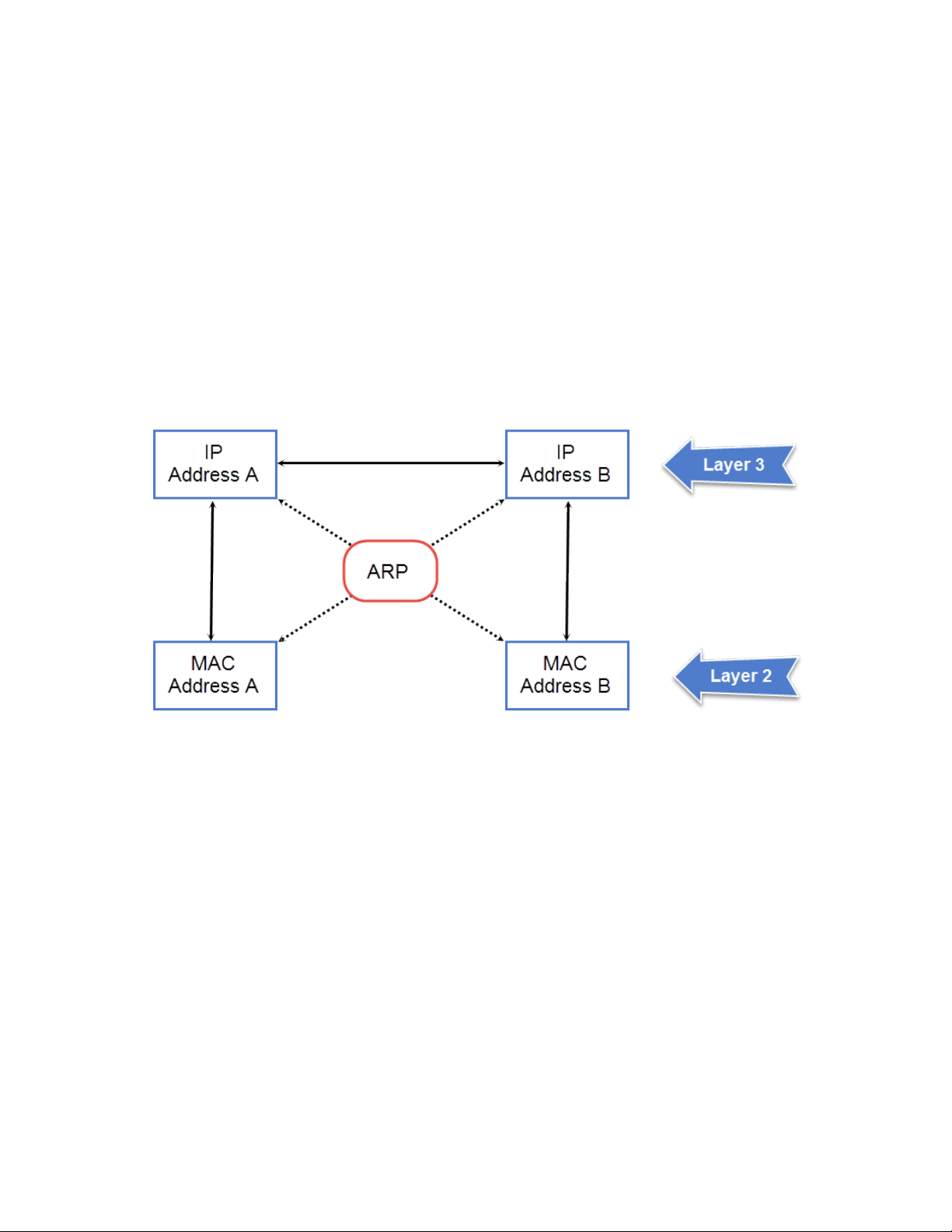
ARP parameter conguration
ARP requests contain the IP address and MAC address of the sender, so all devices that receive the request learn the MAC address and
IP address of the sender and can update their own ARP caches accordingly.
NOTE
The ARP request broadcast is a MAC broadcast, which means the broadcast goes only to devices that are directly attached to
the Layer 3 switch. A MAC broadcast is not routed to other networks. However, some routers, including Brocade Layer 3
switches, can be congured to reply to ARP requests from one network on behalf of devices on another network.
NOTE
If the router receives an ARP request packet that it is unable to deliver to the nal destination because of the ARP timeout and
no ARP response is received (the Layer 3 switch knows of no route to the destination address), the router sends an ICMP Host
Unreachable message to the source.
FIGURE 1 ARP supplies the MAC address corresponding to an IP address
If Device A wants to communicate with Device B, knowing the IP address of Device B is not sucient; the MAC address is also required.
ARP supplies the MAC address.
Rate limiting ARP packets
You can limit the number of ARP packets the Brocade device accepts during each second. By default, the software does not limit the
number of ARP packets the device can receive. Since the device sends ARP packets to the CPU for processing, if a device in a busy
network receives a high number of ARP packets in a short period of time, some CPU processing might be deferred while the CPU
processes the ARP packets.
To prevent the CPU from becoming
will accept each second. When you congure an ARP rate limit, the device accepts up to the maximum number of packets you specify,
but drops additional ARP packets received during the one-second interval. When a new one-second interval starts, the counter restarts at
zero, so the device again accepts up to the maximum number of ARP packets you specied, but drops additional packets received within
the interval.
24 53-1003903-04
ooded by ARP packets in a busy network, you can restrict the number of ARP packets the device
Brocade FastIron Layer 3 Routing Conguration Guide
Page 25

ARP parameter conguration
To limit the number of ARP packets the device will accept each second, enter the rate-limit-arp command at the global CONFIG level of
the CLI.
device(config)# rate-limit-arp 100
This command
during a one-second interval, the device drops the additional ARP packets during the remainder of that one-second interval.
Syntax:[no] rate-limit-arp num
The num variable species the number of ARP packets and can be from 0 through 100. If you specify 0, the device will not accept any
ARP packets.
congures the device to accept up to 100 ARP packets each second. If the device receives more than 100 ARP packets
NOTE
If you want to change a previously congured the ARP rate limiting policy, you must remove the previously congured policy
using the no rate-limit-arp command before entering the new policy.
Changing the ARP aging period
When the Layer 3 switch places an entry in the ARP cache, the Layer 3 switch also starts an aging timer for the entry. The aging timer
ensures that the ARP cache does not retain learned entries that are no longer valid. An entry can become invalid when the device with the
MAC address of the entry is no longer on the network.
The ARP age
change the ARP age to a value from 0 through 240 minutes. You cannot change the ARP age on Layer 2 switches. If you set the ARP
age to zero, aging is disabled and entries do not age out.
aects dynamic (learned) entries only, not static entries. The default ARP age is ten minutes. On Layer 3 switches, you can
NOTE
Host devices connected to an ICX 7750 that also have a valid IP address and reply periodically to the arp request are not timed
out, even if no trac is destined for the device. This behavior is restricted to only ICX 7750 devices.
To globally change the ARP aging parameter to 20 minutes, enter the ip arp-age command.
device(config)# ip arp-age 20
Syntax: [no] ip arp-age num
The num parameter species the number of minutes, which can be from 0 through 240. The default is 10. If you specify 0, aging is
disabled.
To override the globally congured IP ARP age on an individual interface, enter the ip arp-age command followed by the new value at
the interface conguration level.
device(config-if-e1000-1/1/1)# ip arp-age 30
Enabling proxy ARP
Proxy ARP allows a Layer 3 switch to answer ARP requests from devices on one network on behalf of devices in another network.
Because ARP requests are MAC-layer broadcasts, they reach only the devices that are directly connected to the sender of the ARP
request. Thus, ARP requests do not cross routers.
For example, if Proxy ARP is enabled on a Layer 3 switch connected to two subnets, 10.10.10.0/24 and 10.20.20.0/24, the Layer 3
switch can respond to an ARP request from 10.10.10.69 for the MAC address of the device with IP address 10.20.20.69. In standard
ARP, a request from a device in the 10.10.10.0/24 subnet cannot reach a device in the 10.20.20.0 subnet if the subnets are on
dierent network cables, and thus is not answered.
Brocade FastIron Layer 3 Routing Conguration Guide
53-1003903-04 25
Page 26

ARP parameter conguration
NOTE
An ARP request from one subnet can reach another subnet when both subnets are on the same physical segment (Ethernet
cable), because MAC-layer broadcasts reach all the devices on the segment.
Proxy ARP is disabled by default on Brocade Layer 3 switches. This feature is not supported on Brocade Layer 2 switches.
You can enable proxy ARP at the Interface level, as well as at the Global CONFIG level, of the CLI.
NOTE
Conguring proxy ARP at the Interface level overrides the global
conguration.
Enabling proxy ARP globally
To enable IP proxy ARP on a global basis, enter the ip proxy-arp command.
device(config)# ip proxy-arp
To again disable IP proxy ARP on a global basis, enter the no ip proxy-arp command.
device(config)# no ip proxy-arp
Syntax: [no] ip proxy-arp
Enabling IP ARP on an interface
NOTE
Conguring proxy ARP at the Interface level overrides the global
conguration.
To enable IP proxy ARP on an interface, enter the following commands.
device(config)# interface ethernet 5
device(config-if-e1000-5)# ip proxy-arp enable
To again disable IP proxy ARP on an interface, enter the following command.
device(config)# interface ethernet 5
device(config-if-e1000-5)# ip proxy-arp disable
Syntax: [no] ip proxy-arp { enable | disable }
NOTE
By default, gratuitous ARP is disabled for local proxy ARP.
Creating static ARP entries
Static ARP entries are added to the ARP cache when they are congured. Static ARP entries are useful in cases where you want to precongure an entry for a device that is not connected to the Layer 3 switch, or you want to prevent a particular entry from aging out.
Brocade Layer 3 switches have a static ARP table, in addition to the regular ARP cache. Unlike static ARP entries, dynamic ARP entries
are removed from the ARP cache if the ARP aging interval expires before the entry is refreshed. Static entries do not age out, regardless
of whether the Brocade device receives an ARP request from the device that has the entry address.
NOTE
You cannot create static ARP entries on a Layer 2 switch.
26 53-1003903-04
Brocade FastIron Layer 3 Routing Conguration Guide
Page 27

ARP parameter conguration
The maximum number of static ARP entries you can congure depends on the software version running on the device.
To create a static ARP entry, enter a command such as the following.
device(config)# arp 1 10.53.4.2 0000.0054.2348 ethernet 1/1/2
Syntax: arp num ip-addr mac-addr ethernet port
The num variable
species the entry number. You can specify a number from 1 up to the maximum number of static entries allowed on
the device.
The ip-addr variable species the IP address of the device that has the MAC address of the entry.
The mac-addr variable species the MAC address of the entry.
Changing the maximum number of entries the static ARP table can hold
NOTE
The basic procedure for changing the static ARP table size is the same as the procedure for changing other congurable cache
or table sizes.
To increase the maximum number of static ARP table entries you can congure on a Brocade Layer 3 switch, enter commands such as
the following at the global CONFIG level of the CLI.
device(config)# system-max ip-static-arp 1000
device(config)# write memory
device(config)# end
device# reload
NOTE
You must save the conguration to the startup-cong le and reload the software after changing the static ARP table size to
place the change into eect.
Syntax: system-max ip-static-arp num
The num variable indicates the maximum number of static ARP entries and can be within one of these ranges, depending on the
software version running on the device.
TABLE 3 Static ARP entry support
Device Default maximum Congurable minimum Congurable maximum
ICX 7250 512 512 6000
ICX 7450 512 512 6000
ICX 7750 512 512 6000
Enabling learning gratuitous ARP
Learning gratuitous ARP enables Brocade Layer 3 devices to learn ARP entries from incoming gratuitous ARP packets from the hosts
which are directly connected. This help achieve faster convergence for the hosts when they are ready to send trac.
A new ARP entry is created when a gratuitous ARP packet is received. If the ARP is already existing, it will be updated with the new
content.
To enable learning gratuitous ARP, enter the following command at the device conguration level.
Brocade (config)# ip arp learn-gratuitous-arp
Syntax: [no] ip arp learn-gratuitous-arp
The no form of the command disables learning gratuitous ARP from the device.
Brocade FastIron Layer 3 Routing Conguration Guide
53-1003903-04 27
Page 28

ARP parameter conguration
Use the show run command to see whether ARP is enabled or disabled. Use the show arp command to see the newly learned ARP
entries.
Use the clear arp command to clear learned ARP entries. Static ARP entries are not removed.
ARP Packet Validation
Validates ARP packets to avoid
To avoid trac interruption or loss, ARP Packet Validation allows the user to detect and drop ARP packets that do not pass the ARP
validation process. ARP Packet Validation is disabled by default and can be enabled at the global conguration level. This functionality
can be congured for the destination MAC address, the IP address and the source MAC address or with a combination of these
parameters. The Ethernet header contains the destination MAC address and source MAC address, while the ARP packet contains the
sender hardware address and target hardware address.
Follow these steps to perform checks on the incoming ARP packets.
1. Enter the global conguration mode.
2. Run the ip arp inspection validate [dst-mac | ip | src-mac] command to perform a check on any incoming ARP packets. Use
one of the following parameters to run the validation check:
• dst-mac
The destination MAC address in the Ethernet header must be the same as the target hardware address in the ARP body.
This validation is performed for the ARP response packet. When the destination MAC address validation is enabled, the
packets with dierent MAC addresses are classied as invalid and are dropped.
• src-mac
The source MAC address in the Ethernet header and the sender hardware address in the ARP body must be the same. This
validation is performed for the ARP request and response packets. When the source MAC validation is enabled, the packets
with dierent MAC addresses are classied as invalid and are dropped.
• ip
Each ARP packet has a sender IP address and target IP address. The target IP address cannot be invalid or an unexpected
IP address in the ARP response packet. The sender IP address cannot be an invalid or an unexpected IP address in the
ARP request and response packets. Addresses include 0.0.0.0, 255.255.255.255, and all IP multicast addresses. When
the IP address validation is enabled, the packets with invalid and unexpected IP addresses are classied as invalid and are
dropped.
trac interruption or loss.
The following example shows ARP packets being validated for the destination MAC address.
device(config)# configuration terminal
device(config)#ip arp inspection validate dst-mac
Ingress ARP packet priority
You can
volume. Ingress ARP packets have a default priority value of 4. At the default priority value, ingress ARP packets may get dropped
because of high trac volume or non-ARP packets with higher priority values. This can cause devices to become unreachable. If the
ingress ARP packets have higher priority values than the default priority value, a high volume of ARP trac may lead to drops in control
trac. This may cause trac loops in the network.
28 53-1003903-04
congure the priority of the ingress ARP packets to an optimum value that depends on your network conguration and trac
NOTE
You cannot change the priority of the ingress ARP packets on the management port.
Brocade FastIron Layer 3 Routing Conguration Guide
Page 29

Reverse Address Resolution Protocol conguration
Conguring the priority of ingress ARP packets
To congure the priority of ingress ARP packets, use the arp-internal-priority priority-value command in global conguration
mode.
The following example shows the priority of ingress ARP packets set to level 7.
Brocade(config)# arp-internal-priority 7
Displaying the ARP table
To display the ARP table, enter the show arp command.
device# show arp
Total number of ARP entries: 2
Entries in default routing instance:
No. IP Address MAC Address Type Age Port Status
1 10.1.1.100 0000.0000.0100 Dynamic 0 1/1/1*2/1/25 Valid
2 10.37.69.129 02e0.5215.cae3 Dynamic 0 mgmt1 Valid
The command displays all ARP entries in the system.
Syntax: show arp
Reverse Address Resolution Protocol conguration
The Reverse Address Resolution Protocol (RARP) provides a simple mechanism for directly-attached IP hosts to boot over the network.
RARP allows an IP host that does not have a means of storing its IP address across power cycles or software reloads to query a directlyattached router for an IP address.
RARP is enabled by default. However, you must create a RARP entry for each host that will use the Layer 3 switch for booting. A RARP
entry consists of the following information:
• The entry number - The entry sequence number in the RARP table.
• The MAC address of the boot client.
• The IP address you want the Layer 3 switch to give to the client.
When a client sends a RARP broadcast requesting an IP address, the Layer 3 switch responds to the request by looking in the RARP
table for an entry that contains the client MAC address:
• If the RARP table contains an entry for the client, the Layer 3 switch sends a unicast response to the client that contains the IP
address associated with the client MAC address in the RARP table.
• If the RARP table does not contain an entry for the client, the Layer 3 switch silently discards the RARP request and does not
reply to the client.
How RARP Diers from BootP and DHCP
RARP, BootP, and DHCP are dierent methods for providing IP addresses to IP hosts when they boot. These methods dier in the
following ways:
• Location of congured host addresses
– RARP requires static conguration of the host IP addresses on the Layer 3 device. The Layer 3 device replies directly to a
host request by sending an IP address you have congured in the RARP table.
Brocade FastIron Layer 3 Routing Conguration Guide
53-1003903-04 29
Page 30

Reverse Address Resolution Protocol conguration
– The Layer 3 device forwards BootP and DHCP requests to a third-party BootP/DHCP server that contains the IP
addresses and other host conguration information.
• Connection of host to boot source (Layer 3 device or BootP/DHCP server)
– RARP requires the IP host to be directly attached to the Layer 3 device.
– An IP host and the BootP/DHCP server can be on dierent networks and on dierent routers as long as the routers are
congured to forward ("help") the host boot request to the boot server.
– You can centrally congure other host parameters on the BootP/DHCP server and supply those parameters to the host
along with its IP address.
To congure the Layer 3 device to forward BootP/DHCP requests when boot clients and boot servers are on dierent subnets on
dierent Layer 3 device interfaces, refer to the DHCP client section in the Brocade FastIron Conguration Guide.
Disabling RARP
RARP is enabled by default. To disable RARP, enter the following command at the global CONFIG level.
device(config)# no ip rarp
Syntax: [no] ip rarp
To re-enable RARP, enter the following command.
device(config)# ip rarp
Creating static RARP entries
You must congure the RARP entries for the RARP table. The Layer 3 switch can send an IP address in reply to a client RARP request
only if create a RARP entry for that client.
To assign a static IP RARP entry for static routes on a Brocade router, enter a command such as the following.
device(config)# rarp 1 0000.0054.2348 10.53.4.2
This command creates a RARP entry for a client with MAC address 0000.0054.2348. When the Layer 3 switch receives a RARP
request from this client, the Layer 3 switch replies to the request by sending IP address 192.53.4.2 to the client.
Syntax: rap number mac-addr ip-addr
The number parameter identies the RARP entry number. You can specify an unused number from 1 to the maximum number of RARP
entries supported on the device. To determine the maximum number of entries supported on the device, refer to the section "Displaying
and modifying system parameter default settings" in the Brocade FastIron Platform and Layer 2 Switching Conguration Guide.
The mac-addr parameter species the MAC address of the RARP client.
The ip-addr parameter species the IP address the Layer 3 switch will give the client in response to the client RARP request.
Changing the maximum number of static RARP entries supported
The number of RARP entries the Layer 3 switch supports depends on how much memory the Layer 3 switch has. To determine how
many RARP entries your Layer 3 switch can have, display the system default information using the procedure in the section "Displaying
system parameter default values" in the Brocade FastIron Platform and Layer 2 Switching
Conguration Guide.
If your Layer 3 switch allows you to increase the maximum number of RARP entries, you can use a procedure in the same section to do
so.
30 53-1003903-04
Brocade FastIron Layer 3 Routing Conguration Guide
Page 31

Dynamic ARP inspection
NOTE
You must save the conguration to the startup-cong le and reload the software after changing the RARP cache size to place
the change into eect.
Dynamic ARP inspection
For enhanced network security, you can congure the Brocade device to inspect and keep track of Dynamic Host Conguration Protocol
(DHCP) assignments.
Dynamic ARP Inspection (DAI) enables the Brocade device to intercept and examine all ARP request and response packets in a subnet
and discard packets with invalid IP-to-MAC address bindings. DAI can prevent common man-in-the-middle (MiM) attacks such as ARP
cache poisoning, and disallow mis-conguration of client IP addresses.
DAI allows only valid ARP requests and responses to be forwarded and supports Multi-VRFs with overlapping address spaces. For more
information on DAI, refer to the Brocade FastIron Security Conguration Guide.
ARP poisoning
ARP provides IP communication within a Layer 2 broadcast domain by mapping an IP address to a MAC address. Before a host can talk
to another host, it must map the IP address to a MAC address
ARP request to resolve the mapping. All computers on the subnet will receive and process the ARP requests, and the host whose IP
address matches the IP address in the request will send an ARP reply.
rst. If the host does not have the mapping in its ARP table, it creates an
An ARP poisoning attack can target hosts, switches, and routers connected to the Layer 2 network by poisoning the ARP caches of
systems connected to the subnet and by intercepting trac intended for other hosts on the subnet. For instance, a malicious host can
reply to an ARP request with its own MAC address, thereby causing other hosts on the same subnet to store this information in their ARP
tables or replace the existing ARP entry. Furthermore, a host can send gratuitous replies without having received any ARP requests. A
malicious host can also send out ARP packets claiming to have an IP address that actually belongs to another host (for example, the
default router). After the attack, all trac from the device under attack ows through the attacker computer and then to the router, switch,
or host.
Dynamic ARP Inspection
Dynamic ARP Inspection (DAI) allows only valid ARP requests and responses to be forwarded.
A Brocade device on which DAI is
• Intercepts ARP packets received by the system CPU
• Inspects all ARP requests and responses received on untrusted ports
• Veries that each of the intercepted packets has a valid IP-to-MAC address binding before updating the local ARP table, or
before forwarding the packet to the appropriate destination
• Drops invalid ARP packets
When you enable DAI on a VLAN, by default, all member ports are untrusted. You must manually congure trusted ports. In a typical
network conguration, ports connected to host ports are untrusted. You congure ports connected to other switches or routers as trusted.
DAI inspects ARP packets received on untrusted ports, as shown in the gure below. DAI carries out the inspection based on IP-to-MAC
address bindings stored in a trusted binding database. For the Brocade device, the binding database is the ARP table and the DHCP
snooping table, which supports DAI, DHCP snooping, and IP Source Guard. To inspect an ARP request packet, DAI checks the source IP
congured does the following:
Brocade FastIron Layer 3 Routing Conguration Guide
53-1003903-04 31
Page 32

Dynamic ARP inspection
address and source MAC address against the ARP table. For an ARP reply packet, DAI checks the source IP, source MAC, destination IP,
and destination MAC addresses. DAI forwards the valid packets and discards those with invalid IP-to-MAC address bindings.
When ARP packets reach a trusted port, DAI lets them through, as shown in the following gure.
FIGURE 2 Dynamic ARP inspection at work
ARP and DHCP snoop entries
DAI uses the IP-to-MAC mappings in the ARP table to validate ARP packets received on untrusted ports. DAI relies on the following
entries:
• Dynamic ARP - Normal ARP learned from trusted ports.
• Static ARP - Statically congured IP/MAC/port mapping.
• Inspection ARP - Statically congured IP-to-MAC mapping, where the port is initially unspecied. The actual physical port
mapping will be resolved and updated from validated ARP packets. Refer to Conguring an inspection ARP entry on page 33.
• DHCP-Snooping ARP - Information collected from snooping DHCP packets when DHCP snooping is enabled on VLANs.
DHCP snooping entries are stored in a dierent table and are not part of the ARP table.
The status of an ARP entry is either pending or valid:
• Valid - The mapping is valid, and the port is resolved. This is always the case for static ARP entries.
• Pending - For normal dynamic ARP entries before they are resolved, and the port is mapped. Their status changes to valid
when they are resolved, and the port is mapped.
Refer to System reboot and the binding database section in the Brocade FastIron DHCP Conguration Guide.
Conguration notes and feature limitations for DAI
The following conguration notes and limitations apply when conguring DAI:
• To run Dynamic ARP Inspection, you must rst enable support for ACL ltering based on VLAN membership or VE port
membership. To do so, enter the following commands at the global conguration level of the CLI.
device(config)# enable ACL-per-port-per-vlan
device(config)# write memory
device(config)# exit
device# reload
32 53-1003903-04
Brocade FastIron Layer 3 Routing Conguration Guide
Page 33

Dynamic ARP inspection
NOTE
You must save the conguration and reload the software to place the change into
eect.
• There is a limit on the number of static ARP inspection entries that can be congured. This is determined by the system-max
parameter max-static-inspect-arp-entries. The maximum value is 1024 and the default value is 512. Changing the system
max values requires a system reload.
• ACLs are supported on member ports of a VLAN on which DHCP snooping and Dynamic ARP Inspection (DAI) are enabled.
• DAI is supported on a VLAN without a VE, or on a VE with or without an assigned IP address.
• DAI is supported on LAG ports.
Dynamic ARP Inspection conguration
Conguring
DAI consists of the following steps.
1. Congure inspection ARP entries for hosts on untrusted ports. Refer to Conguring an inspection ARP entry on page 33.
2. Enable DAI on a VLAN to inspect ARP packets. Refer to Enabling DAI on a VLAN on page 33.
3. Congure the trust settings of the VLAN members. ARP packets received on trusted ports bypass the DAI validation process.
ARP packets received on untrusted ports go through the DAI validation process. Refer to Enabling trust on a port on page 34.
4. Enable DHCP snooping to populate the DHCP snooping IP-to-MAC address binding database.
Dynamic ARP inspection is disabled by default and the trust setting for ports is by default untrusted.
Conguring an inspection ARP entry
Static ARP and static inspection ARP entries must be congured for hosts on untrusted ports. Otherwise, when DAI checks ARP packets
from these hosts against entries in the ARP table, it will not nd any entries for them, and the Brocade device will not allow and learn ARP
from an untrusted host.
To congure an inspection ARP entry, enter a command such as the following.
device(config)# arp 10.20.20.12 0000.0002.0003 inspection
This command denes an inspection ARP entry in the static ARP table, mapping a device IP address 10.20.20.12 with its MAC address
0000.0002.0003. The ARP entry will be moved to the ARP table once the DAI receives a valid ARP packet.
Dynamic ARP Inspection must be enabled to use static ARP inspection entries.
Syntax: [no] arp ip-addr mac-addr inspection
The ip-addr mac-addr parameter species a device IP address and MAC address pairing.
Enabling DAI on a VLAN
DAI is disabled by default. To enable DAI on an existing VLAN, enter the following command.
device(config)# ip arp inspection vlan 2
The command enables DAI on VLAN 2. ARP packets from untrusted ports in VLAN 2 will undergo DAI inspection.
Syntax: [no] ip arp inspection vlan vlan-number
The vlan-number variable
Brocade FastIron Layer 3 Routing Conguration Guide
53-1003903-04 33
species the ID of a congured VLAN.
Page 34

Dynamic ARP inspection
Enabling trust on a port
The default trust setting for a port is untrusted. For ports that are connected to host ports, leave their trust settings as untrusted. If the
port is part of a LAG, enable ARP inspection trust on the primary port of the LAG.
To enable trust on a port, enter commands such as the following.
device(config)# interface ethernet 1/1/4
device(config-if-e10000-1/1/4)# arp inspection trust
The commands change the CLI to the interface conguration level of port 1/1/4 and set the trust setting of port 1/1/4 to trusted.
Syntax: [no] arp inspection trust
Disabling or re-enabling syslog messages for DAI
You can disable or re-enable syslog messages for Dynamic ARP Inspection. Syslog messages are enabled by default on the device.
1. Enter global conguration mode.
2. Enter the ip arp inspection syslog disable command to disable syslog messages. Use the no form of the command to reenable syslog messages for DAI.
The following example shows disabling the syslog messages for DAI.
device(config)# ip arp inspection syslog disable
Multi-VRF support for DAI
DAI supports Multi-VRF (Virtual Routing and Forwarding) instances. You can deploy multiple VRFs on a Brocade Ethernet switch. Each
VLAN having a Virtual Ethernet (VE) interface is assigned to a VRF.
You can enable DAI on individual VLANs and assign any interface as the ARP inspection trust interface. If an interface is a tagged port in
this VLAN, you can turn on the trust port per VRF, so that
To congure DAI to support a VRF instance, do the following:
• Enable the acl-per-port-per-vlan setting. DAI requires that the acl-per-port-per-vlan setting be enabled.
Brocade(config)# enable acl-per-port-per-vlan
Reload required. Please write memory and then reload or power cycle.
• Congure DAI on a VLAN using the ip arp inspection vlan vlan-id command.
Brocade(config)# ip arp inspection vlan 2
Syntax: ip arp inspection vlan vlan-id
• To add a static ARP inspection entry for a specic VRF, use the arp ip-address mac-address inspection command in the VRF
CLI context.
Brocade(config-vrf-one-ipv4)# arp 5.5.5.5 00a2.bbaa.0033 inspection
Syntax: arp ip-address mac-address inspection
trac intended for other VRF VLANs will not be trusted.
Enabling trust on a port for a
The default trust setting for a port is untrusted. For ports that are connected to host ports, leave their trust settings as untrusted.
34 53-1003903-04
specic VRF
Brocade FastIron Layer 3 Routing Conguration Guide
Page 35

To enable trust on a port for a specic VRF, enter commands such as the following.
Brocade(config)# interface ethernet 1/1/4
Brocade(config-if-e10000-1/1/4)# arp inspection trust vrf vrf2
Dynamic ARP inspection
The commands change the CLI to the interface
conguration level of port 1/1/4 and set the trust setting of port 1/1/4 on VRF 2 to
trusted.
Syntax: [no] arp inspection trust vrf vrf-name
Displaying ARP inspection status and ports
To display the ARP inspection status for a VLAN and the trusted or untrusted port, enter the following command.
device# show ip arp inspection vlan 2
IP ARP inspection VLAN 2: Disabled
Trusted Ports : ethe 1/1/4
Untrusted Ports : ethe 2/1/1 to 2/1/3 ethe 4/1/1 to 4/1/24 ethe 6/1/1 to 6/1/4 ethe 8/1/1 to 8/1/4
Syntax: show ip arp inspection vlan vlan_id
The vlan_id variable
species the ID of a congured VLAN.
Brocade FastIron Layer 3 Routing Conguration Guide
53-1003903-04 35
Page 36

36 53-1003903-04
Brocade FastIron Layer 3 Routing Conguration Guide
Page 37

IP Addressing
• IP addressing overview....................................................................................................................................................................................37
• IP conguration overview...............................................................................................................................................................................37
• Basic IP parameters and defaults - Layer 3 switches........................................................................................................................44
• Basic IP parameters and defaults - Layer 2 switches........................................................................................................................49
• Basic IP conguration......................................................................................................................................................................................51
• Conguring IP parameters - Layer 3 switches..................................................................................................................................... 51
• Conguring IP parameters - Layer 2 switches..................................................................................................................................... 80
• IPv4 point-to-point GRE tunnels ...............................................................................................................................................................84
• Bandwidth for IP interfaces........................................................................................................................................................................... 99
• User-congurable MAC address per IP interface.............................................................................................................................102
• Modifying and displaying Layer 3 system parameter limits.........................................................................................................104
• Enabling or disabling routing protocols.................................................................................................................................................105
• Enabling or disabling Layer 2 switching............................................................................................................................................... 106
• Conguring a Layer 3 Link Aggregration Group (LAG)..................................................................................................................106
• Disabling IP checksum check................................................................................................................................................................... 107
• Displaying IP conguration information and statistics.................................................................................................................... 108
IP addressing overview
IPv4 uses a 32-bit addressing system designed for use in packet-switched networks.
IPv4 is the Internet protocol that is most commonly used currently throughout the world. IPv4 uses a 32-bit addressing system and is
represented in a 4-byte dotted decimal format: x.x.x.x.
IP conguration overview
Brocade Layer 2 switches and Layer 3 switches support Internet Protocol version 4 (IPv4) and IPv6. IP support on Brocade Layer 2
switches consists of basic services to support management access and access to a default gateway.
Full Layer 3 support
IP support on Brocade full Layer 3 switches includes all of the following, in addition to a highly
services including Address Resolution Protocol (ARP), ICMP Router Discovery Protocol (IRDP), and Reverse ARP (RARP):
• Route exchange protocols:
– Routing Information Protocol (RIP)
– Open Shortest Path First (OSPF)
– Border Gateway Protocol version 4 (BGP4)
• Multicast protocols:
– Internet Group Management Protocol (IGMP)
– Protocol Independent Multicast Dense (PIM-DM)
– Protocol Independent Multicast Sparse (PIM-SM)
• Router redundancy protocols:
– Virtual Router Redundancy Protocol Extended (VRRP-E)
congurable implementation of basic IP
Brocade FastIron Layer 3 Routing Conguration Guide
53-1003903-04 37
Page 38

IP conguration overview
– Virtual Router Redundancy Protocol (VRRP)
IP interfaces
NOTE
This section describes IPv4 addresses. For information about IPv6 addresses, refer to the IPv6 addressing chapter.
Brocade Layer 3 switches and Layer 2 switches allow you to congure IP addresses. On Layer 3 switches, IP addresses are associated
with individual interfaces. On Layer 2 switches, a single IP address serves as the management access address for the entire device.
All Brocade Layer 3 switches and Layer 2 switches support conguration and display of IP addresses in classical subnet format (for
example, 192.168.1.1 255.255.255.0) and Classless Interdomain Routing (CIDR) format (for example, 192.168.1.1/24). You can use
either format when conguring IP address information. IP addresses are displayed in classical subnet format by default but you can
change the display format to CIDR.
Layer 3 switches
Brocade Layer 3 switches allow you to
• Ethernet ports
• Virtual routing interfaces (used by VLANs to route among one another)
• Loopback interfaces
• GRE tunnels
Each IP address on a Layer 3 switch must be in a dierent subnet. You can have only one interface that is in a given subnet. For example,
you can congure IP addresses 192.168.1.1/24 and 192.168.2.1/24 on the same Layer 3 switch, but you cannot congure
192.168.1.1/24 and 192.168.1.2/24 on the same Layer 3 switch.
You can congure multiple IP addresses on the same interface.
The number of IP addresses you can congure on an individual interface depends on the Layer 3 switch model. To display the maximum
number of IP addresses and other system parameters you can congure on a Layer 3 switch, refer to "Displaying and modifying system
parameter default settings" section in the Brocade FastIron Platform and Layer 2 Switching Conguration Guide.
You can use any of the IP addresses you congure on the Layer 3 switch for Telnet, Web management, or SNMP access.
congure IP addresses on the following types of interfaces:
Layer 2 switches
You can
for Telnet access, Web management access, and SNMP access.
You also can specify the default gateway for forwarding trac to other subnets.
congure an IP address on a Brocade Layer 2 switch for management access to the Layer 2 switch. An IP address is required
38 53-1003903-04
Brocade FastIron Layer 3 Routing Conguration Guide
Page 39

IP packet ow through a Layer 3 switch
FIGURE 3 IP Packet ow through a Brocade Layer 3 switch
IP conguration overview
1. When the Layer 3 switch receives an IP packet, the Layer 3 switch checks for lters on the receiving interface.1 If a deny lter on
the interface denies the packet, the Layer 3 switch discards the packet and performs no further processing, except generating a
Syslog entry and SNMP message, if logging is enabled for the lter.
1
The lter can be an Access Control List (ACL) or an IP access policy.
Brocade FastIron Layer 3 Routing Conguration Guide
53-1003903-04 39
Page 40

IP conguration overview
2. If the packet is not denied at the incoming interface, the Layer 3 switch looks in the session table for an entry that has the same
source IP address and TCP or UDP port as the packet. If the session table contains a matching entry, the Layer 3 switch
immediately forwards the packet, by addressing it to the destination IP address and TCP or UDP port listed in the session table
entry and sending the packet to a queue on the outgoing ports listed in the session table. The Layer 3 switch selects the queue
based on the Quality of Service (QoS) level associated with the session table entry.
3. If the session table does not contain an entry that matches the packet source address and TCP or UDP port, the Layer 3 switch
looks in the IP forwarding cache for an entry that matches the packet destination IP address. If the forwarding cache contains a
matching entry, the Layer 3 switch forwards the packet to the IP address in the entry. The Layer 3 switch sends the packet to a
queue on the outgoing ports listed in the forwarding cache. The Layer 3 switch selects the queue based on the Quality of
Service (QoS) level associated with the forwarding cache entry.
4. If the IP forwarding cache does not have an entry for the packet, the Layer 3 switch checks the IP route table for a route to the
packet destination. If the IP route table has a route, the Layer 3 switch makes an entry in the session table or the forwarding
cache, and sends the route to a queue on the outgoing ports:
• – If the running-cong contains an IP access policy for the packet, the software makes an entry in the session table. The
Layer 3 switch uses the new session table entry to forward subsequent packets from the same source to the same
destination.
– If the running-cong does not contain an IP access policy for the packet, the software creates a new entry in the
forwarding cache. The Layer 3 switch uses the new cache entry to forward subsequent packets to the same
destination.
The following sections describe the IP tables and caches:
• ARP cache and static ARP table
• IP route table
• IP forwarding cache
• Layer 4 session table
The software enables you to display these tables. You also can change the capacity of the tables on an individual basis if
needed by changing the memory allocation for the table.
ARP cache and static ARP table
The ARP cache contains entries that map IP addresses to MAC addresses. Generally, the entries are for devices that are directly attached
to the Layer 3 switch.
An exception is an ARP entry for an interface-based static IP route that goes to a destination that is one or more router hops away. For
this type of entry, the MAC address is either the destination device MAC address or the MAC address of the router interface that
answered an ARP request on behalf of the device, using proxy ARP.
ARP cache
The ARP cache can contain dynamic (learned) entries and static
ARP cache when the Layer 3 switch learns a device MAC address from an ARP request or ARP reply from the device.
The software can learn an entry when the Layer 2 switch or Layer 3 switch receives an ARP request from another IP forwarding device or
an ARP reply. Here is an example of a dynamic entry:
(user-congured) entries. The software places a dynamic entry in the
IP Address MAC Address Type Age Port
1 10.95.6.102 0000.00fc.ea21 Dynamic 0 6
Each entry contains the destination device IP address and MAC address.
40 53-1003903-04
Brocade FastIron Layer 3 Routing Conguration Guide
Page 41

IP conguration overview
Static ARP table
In addition to the ARP cache, Layer 3 switches have a static ARP table. Entries in the static ARP table are user-congured. You can add
entries to the static ARP table regardless of whether or not the device the entry is for is connected to the Layer 3 switch.
NOTE
Layer 3 switches have a static ARP table. Layer 2 switches do not.
The software places an entry from the static ARP table into the ARP cache when the entry interface comes up.
Here is an example of a static ARP entry.
Index IP Address MAC Address Port
1 10.95.6.111 0000.003b.d210 1/1/1
Each entry lists the information you specied when you created the entry.
IP route table
The IP route table contains paths to IP destinations.
NOTE
Layer 2 switches do not have an IP route table. A Layer 2 switch sends all packets addressed to another subnet to the default
gateway, which you specify when you congure the basic IP information on the Layer 2 switch.
The IP route table can receive the paths from the following sources:
• A directly-connected destination, which means there are no router hops to the destination
• A static IP route, which is a user-congured route
• A route learned through RIP
• A route learned through OSPF
• A route learned through BGP4
The IP route table contains the best path to a destination:
• When the software receives paths from more than one of the sources listed above, the software compares the administrative
distance of each path and selects the path with the lowest administrative distance. The administrative distance is a protocolindependent value from 1 through 255.
• When the software receives two or more best paths from the same source and the paths have the same metric (cost), the
software can load share trac among the paths based on destination host or network address (based on the conguration and
the Layer 3 switch model).
Here is an example of an entry in the IP route table.
Destination NetMask Gateway Port Cost Type
10.1.0.0 255.255.0.0 10.1.1.2 1/1/1 2 R
Each IP route table entry contains the destination IP address and subnet mask and the IP address of the next-hop router interface to the
destination. Each entry also indicates the port attached to the destination or the next-hop to the destination, the route IP metric (cost), and
the type. The type indicates how the IP route table received the route.
To increase the size of the IP route table for learned and static routes, refer to the section "Displaying and modifying system parameter
default settings" in the Brocade FastIron Layer 2 Switching
Conguration Guide
• For learned routes, modify theip-route parameter.
• For static routes, modify the ip-static-route parameter.
Brocade FastIron Layer 3 Routing Conguration Guide
53-1003903-04 41
Page 42

IP conguration overview
IP forwarding cache
The IP forwarding cache provides a fast-path mechanism for forwarding IP packets. The cache contains entries for IP destinations. When
a Brocade Layer 3 switch has completed processing and addressing for a packet and is ready to forward the packet, the device checks
the IP forwarding cache for an entry to the packet destination:
• If the cache contains an entry with the destination IP address, the device uses the information in the entry to forward the packet
out the ports listed in the entry. The destination IP address is the address of the packet nal destination. The port numbers are
the ports through which the destination can be reached.
• If the cache does not contain an entry and the trac does not qualify for an entry in the session table instead, the software can
create an entry in the forwarding cache.
Each entry in the IP forwarding cache has an age timer. If the entry remains unused for ten minutes, the software removes the entry. The
age timer is not congurable.
Here is an example of an entry in the IP forwarding cache.
IP Address Next Hop MAC Type Port Vlan Pri
1 192.168.1.11 DIRECT 0000.0000.0000 PU n/a 0
Each IP forwarding cache entry contains the IP address of the destination, and the IP address and MAC address of the next-hop router
interface to the destination. If the destination is actually an interface
information indicates this. The port through which the destination is reached is also listed, as well as the VLAN and Layer 4 QoS priority
associated with the destination if applicable.
congured on the Layer 3 switch itself, as shown here, then next-hop
NOTE
You cannot add static entries to the IP forwarding cache, although you can increase the number of entries the cache can
contain. Refer to the section "Displaying and modifying system parameter default settings" in the Brocade FastIron Layer 2
Switching Conguration Guide.
Layer 4 session table
The Layer 4 session provides a fast path for forwarding packets. A session is an entry that contains complete Layer 3 and Layer 4
information for a ow of trac. Layer 3 information includes the source and destination IP addresses. Layer 4 information includes the
source and destination TCP and UDP ports. For comparison, the IP forwarding cache contains the Layer 3 destination address but does
not contain the other source and destination address information of a Layer 4 session table entry.
The Layer 2 switch or Layer 3 switch selects the session table instead of the IP forwarding table for fast-path forwarding for the following
features:
• Layer 4 Quality-of-Service (QoS) policies
• IP access policies
To increase the size of the session table, refer to the section "Displaying and modifying system parameter default settings" in the
Brocade FastIron Layer 2 Switching Conguration Guide. The ip-qos-session parameter controls the size of the session table.
IP route exchange protocols
Brocade Layer 3 switches support the following IP route exchange protocols:
• Routing Information Protocol (RIP)
• Open Shortest Path First (OSPF)
• Border Gateway Protocol version 4 (BGP4)
42 53-1003903-04
Brocade FastIron Layer 3 Routing Conguration Guide
Page 43

IP conguration overview
All these protocols provide routes to the IP route table. You can use one or more of these protocols, in any combination. The protocols
are disabled by default.
IP multicast protocols
Brocade Layer 3 switches also support the following Internet Group Membership Protocol (IGMP) based IP multicast protocols:
• Protocol Independent Multicast - Dense mode (PIM-DM)
• Protocol Independent Multicast - Sparse mode (PIM-SM)
For conguration information, refer to "IP Multicast Protocols" in the Brocade FastIron IP Multicast Conguration Guide.
NOTE
Brocade Layer 3 switches support IGMP and can forward IP multicast packets. Refer to the "IP Multicast Trac Reduction"
chapter in the Brocade FastIron IP Multicast Conguration Guide.
IP interface redundancy protocols
You can congure a Brocade Layer 3 switch to back up an IP interface congured on another Brocade Layer 3 switch. If the link for the
backed up interface becomes unavailable, the other Layer 3 switch can continue service for the interface. This feature is especially useful
for providing a backup to a network default gateway.
Brocade Layer 3 switches support the following IP interface redundancy protocols:
• Virtual Router Redundancy Protocol (VRRP) - A standard router redundancy protocol based on RFC 2338. You can use VRRP
to congure Brocade Layer 3 switches and third-party routers to back up IP interfaces on other Brocade Layer 3 switches or
third-party routers.
• Virtual Router Redundancy Protocol Extended (VRRP-E) - A Brocade extension to standard VRRP that adds additional features
and overcomes limitations in standard VRRP. You can use VRRP-E only on Brocade Layer 3 switches.
ACLs and IP access policies
Brocade Layer 3 switches provide two mechanisms for ltering IP trac:
• Access Control Lists (ACLs)
• IP access policies
Both methods allow you to lter packets based on Layer 3 and Layer 4 source and destination information.
ACLs also provide great exibility by providing the input to various other ltering mechanisms such as route maps, which are used by
BGP4.
IP access policies allow you to congure QoS based on sessions (Layer 4 trac ows).
Only one of these ltering mechanisms can be enabled on a Brocade device at a time. Brocade devices can store forwarding information
for both methods of ltering in the session table.
For conguration information, refer to the chapter "Rule-Based IP ACLs" in the Brocade FastIron Security Conguration Guide.
Brocade FastIron Layer 3 Routing Conguration Guide
53-1003903-04 43
Page 44

Basic IP parameters and defaults - Layer 3 switches
Basic IP parameters and defaults - Layer 3 switches
IP is enabled by default. The following IP-based protocols are all disabled by default:
• Routing protocols:
– Routing Information Protocol (RIP)
– Open Shortest Path First (OSPF)
– Border Gateway Protocol version 4 (BGP4)
• Multicast protocols:
– Internet Group Membership Protocol (IGMP)
– Protocol Independent Multicast Dense (PIM-DM)
– Protocol Independent Multicast Sparse (PIM-SM)
• Router redundancy protocols:
– Virtual Router Redundancy Protocol Extended (VRRP-E)
– Virtual Router Redundancy Protocol (VRRP)
When parameter changes take eect
Most IP parameters described in this chapter are dynamic. They take eect immediately, as soon as you enter the CLI command or
select the Web Management Interface option. You can verify that a dynamic change has taken eect by displaying the running-cong. To
display the running-cong, enter the show running-cong or write terminal command at any CLI prompt. (You cannot display the
running-cong from the Web Management Interface.)
To save a conguration change permanently so that the change remains in eect following a system reset or software reload, save the
change to the startup-cong le:
• To save conguration changes to the startup-cong le, enter the write memory command from the Privileged EXEC level of
any conguration level of the CLI.
• To save the conguration changes using the Web Management Interface, select the Save link at the bottom of the dialog. Select
Yes when prompted to save the conguration change to the startup-cong le on the device ash memory. You also can access
the dialog for saving conguration changes by clicking on Command in the tree view, then clicking on Save to Flash.
Changes to memory allocation require you to reload the software after you save the changes to the startup-cong le. When reloading
the software is required to complete a conguration change described in this chapter, the procedure that describes the conguration
change includes a step for reloading the software.
IP global parameters - Layer 3 switches
TABLE 4 IP global parameters - Layer 3 switches
Parameter Description Default
IP state The Internet Protocol, version 4 Enabled
NOTE
You cannot disable IP.
IP address and mask notation Format for displaying an IP address and its
network mask information. You can enable one
of the following:
• Class-based format; example:
192.168.1.1 255.255.255.0
44 53-1003903-04
Class-based
Brocade FastIron Layer 3 Routing Conguration Guide
Page 45

TABLE 4 IP global parameters - Layer 3 switches (continued)
Parameter Description Default
• Classless Interdomain Routing (CIDR)
format; example: 192.168.1.1/24
Basic IP parameters and defaults - Layer 3 switches
NOTE
Changing this parameter aects the
display of IP addresses, but you can
enter addresses in either format
regardless of the display setting.
Router ID The value that routers use to identify themselves
to other routers when exchanging route
information. OSPF and BGP4 use router IDs to
identify routers. RIP does not use the router ID.
Maximum Transmission Unit (MTU) The maximum length an Ethernet packet can be
without being fragmented.
Address Resolution Protocol (ARP) A standard IP mechanism that routers use to
learn the Media Access Control (MAC) address
of a device on the network. The router sends the
IP address of a device in the ARP request and
receives the device MAC address in an ARP
reply.
ARP rate limiting You can specify a maximum number of ARP
packets the device will accept each second. If the
device receives more ARP packets than you
specify, the device drops additional ARP packets
for the remainder of the one-second interval.
ARP age The amount of time the device keeps a MAC
address learned through ARP in the device ARP
cache. The device resets the timer to zero each
time the ARP entry is refreshed and removes the
entry if the timer reaches the ARP age.
NOTE
You also can change the ARP age on
an individual interface basis.
The IP address congured on the lowest-
numbered loopback interface.
If no loopback interface is congured, then the
lowest-numbered IP address congured on the
device.
1500 bytes for Ethernet II encapsulation
1492 bytes for SNAP encapsulation
Enabled
Disabled
10 minutes
Proxy ARP An IP mechanism a router can use to answer an
Disabled
ARP request on behalf of a host by replying with
the router's own MAC address instead of the
host.
Static ARP entries An ARP entry you place in the static ARP table.
No entries
Static entries do not age out.
Time to Live (TTL) The maximum number of routers (hops) through
64 hops
which a packet can pass before being discarded.
Each router decreases a packet TTL by 1 before
forwarding the packet. If decreasing the TTL
causes the TTL to be 0, the router drops the
packet instead of forwarding it.
Directed broadcast forwarding A directed broadcast is a packet containing all
Disabled
ones (or in some cases, all zeros) in the host
portion of the destination IP address. When a
router forwards such a broadcast, it sends a copy
of the packet out each of its enabled IP
interfaces.
Brocade FastIron Layer 3 Routing Conguration Guide
53-1003903-04 45
Page 46

Basic IP parameters and defaults - Layer 3 switches
TABLE 4 IP global parameters - Layer 3 switches (continued)
Parameter Description Default
NOTE
You also can enable or disable this
parameter on an individual interface
basis.
Directed broadcast mode The packet format the router treats as a directed
broadcast. The following formats can be directed
broadcasts:
• All ones in the host portion of the
packet destination address.
• All zeroes in the host portion of the
packet destination address.
Source-routed packet forwarding A source-routed packet contains a list of IP
addresses through which the packet must pass
to reach its destination.
Internet Control Message Protocol (ICMP)
messages
The Brocade Layer 3 switch can send the
following types of ICMP messages:
• Echo messages (ping messages)
• Destination Unreachable messages
ICMP Router Discovery Protocol (IRDP) An IP protocol a router can use to advertise the
IP addresses of its router interfaces to directly
attached hosts. You can enable or disable the
protocol, and change the following protocol
parameters:
• Forwarding method (broadcast or
multicast)
• Hold time
• Maximum advertisement interval
• Minimum advertisement interval
• Router preference level
All ones
NOTE
If you enable all-zeroes directed
broadcasts, all-ones directed
broadcasts remain enabled.
Enabled
Enabled
Disabled
NOTE
You also can enable or disable IRDP
and congure the parameters on an
individual interface basis.
Reverse ARP (RARP) An IP mechanism a host can use to request an
Enabled
IP address from a directly attached router when
the host boots.
Static RARP entries An IP address you place in the RARP table for
No entries
RARP requests from hosts.
NOTE
You must enter the RARP entries
manually. The Layer 3 switch does
not have a mechanism for learning or
dynamically generating RARP
entries.
Maximum BootP relay hops The maximum number of hops away a BootP
Four
server can be located from a router and still be
used by the router clients for network booting.
Domain name for Domain Name Server (DNS)
resolver
46 53-1003903-04
A domain name (for example,
brocade.router.com) you can use in place of an
None congured
Brocade FastIron Layer 3 Routing Conguration Guide
Page 47

TABLE 4 IP global parameters - Layer 3 switches (continued)
Parameter Description Default
IP address for certain operations such as IP
pings, trace routes, and Telnet management
connections to the router.
DNS default gateway addresses A list of gateways attached to the router through
which clients attached to the router can reach
DNSs.
IP load sharing A Brocade feature that enables the router to
balance trac to a specic destination across
multiple equal-cost paths.
IP load sharing uses a hashing algorithm based
on the source IP address, destination IP address,
protocol eld in the IP header, TCP, and UDP
information.
You can specify the number of load-sharing
paths depending on the device you are
conguring. The maximum number of paths the
device supports is a value from 2 through 8. The
default value is 4. On the Brocade ICX 7750,
the value range for the maximum number of
load-sharing paths is from 2 through 32 which
is controlled by the system-max max-ecmp
command.
None congured
Enabled
Basic IP parameters and defaults - Layer 3 switches
NOTE
Load sharing is sometimes called
equal-cost multi-path (ECMP).
Maximum IP load sharing paths The maximum number of equal-cost paths
Four
across which the Layer 3 switch is allowed to
distribute trac.
Origination of default routes You can enable a router to originate default
Disabled
routes for the following route exchange
protocols, on an individual protocol basis:
• OSPF
• BGP4
Default network route The router uses the default network route if the
None congured
IP route table does not contain a route to the
destination and also does not contain an explicit
default route (0.0.0.0 0.0.0.0 or 0.0.0.0/0).
Static route An IP route you place in the IP route table. No entries
Source interface The IP address the router uses as the source
address for Telnet, RADIUS, or TACACS/
The lowest-numbered IP address on the
interface the packet is sent on.
TACACS+ packets originated by the router. The
router can select the source address based on
either of the following:
• The lowest-numbered IP address on
the interface the packet is sent on.
• The lowest-numbered IP address on a
specic interface. The address is used
as the source for all packets of the
specied type regardless of interface
the packet is sent on.
Brocade FastIron Layer 3 Routing Conguration Guide
53-1003903-04 47
Page 48

Basic IP parameters and defaults - Layer 3 switches
IP interface parameters - Layer 3 switches
TABLE 5 IP interface parameters - Layer 3 switches
Parameter Description Default
IP state The Internet Protocol, version 4 Enabled
NOTE
You cannot disable IP.
IP address A Layer 3 network interface address
NOTE
Layer 2 switches have a single IP
address used for management
access to the entire device. Layer 3
switches have separate IP addresses
on individual interfaces.
Encapsulation type The format of the packets in which the router
encapsulates IP datagrams. The encapsulation
format can be one of the following:
• Ethernet II
• SNAP
Maximum Transmission Unit (MTU) The maximum length (number of bytes) of an
encapsulated IP datagram the router can
forward.
Delay L3 notications When all ports in the VLAN go into the non-
forwarding state, the device waits for the
congured time before notifying the Layer 3
protocols of the VE down event.
NOTE
Available on the VE interface only.
ARP age Locally overrides the global setting. Ten minutes
Directed broadcast forwarding Locally overrides the global setting. Disabled
ICMP Router Discovery Protocol (IRDP) Locally overrides the global IRDP settings. Disabled
DHCP gateway stamp The router can assist DHCP/BootP Discovery
packets from one subnet to reach DHCP/BootP
servers on a dierent subnet by placing the IP
address of the router interface that receives the
request in the request packet Gateway eld.
You can override the default and specify the IP
address to use for the Gateway eld in the
packets.
None congured
Ethernet II
1500 for Ethernet II encapsulated packets
1492 for SNAP encapsulated packets
Delay time is not congured
The lowest-numbered IP address on the
interface that receives the request
NOTE
Some devices have a factory default,
such as 10.157.22.154, used for
troubleshooting during installation.
For Layer 3 switches, the address is
on unit 1/slot 1/ port 1 (or 1/1/1).
NOTE
UDP broadcast forwarding for client
DHCP/BootP requests (bootps)
must be enabled (this is enabled by
default) and you must congure an
IP helper address (the server IP
address or a directed broadcast to
the server subnet) on the port
connected to the client.
48 53-1003903-04
Brocade FastIron Layer 3 Routing Conguration Guide
Page 49

TABLE 5 IP interface parameters - Layer 3 switches (continued)
Parameter Description Default
DHCP Client-Based Auto-Conguration Allows the switch to obtain IP addresses from a
DHCP host automatically, for either a specied
(leased) or innite period of time.
DHCP Server All FastIron devices can be congured to
function as DHCP servers.
UDP broadcast forwarding The router can forward UDP broadcast packets
for UDP applications such as BootP. By
forwarding the UDP broadcasts, the router
enables clients on one subnet to nd servers
attached to other subnets.
NOTE
To completely enable a client UDP
application request to nd a server
on another subnet, you must
congure an IP helper address
consisting of the server IP address or
the directed broadcast address for
the subnet that contains the server.
Refer to the next row.
Enabled
Disabled
The router helps forward broadcasts for the
following UDP application protocols:
Basic IP parameters and defaults - Layer 2 switches
• bootps
• dns
• netbios-dgm
• netbios-ns
• tacacs
• tftp
• time
IP helper address The IP address of a UDP application server
(such as a BootP or DHCP server) or a directed
broadcast address. IP helper addresses allow the
router to forward requests for certain UDP
applications from a client on one subnet to a
server on another subnet.
None congured
Basic IP parameters and defaults - Layer 2 switches
IP is enabled by default. The following tables list the Layer 2 switch IP parameters, their default values, and where to nd conguration
information.
NOTE
Brocade Layer 2 switches also provide IP multicast forwarding, which is enabled by default. For information about this feature,
refer to "IP Multicast Trac Reduction" in the Brocade FastIron IP Multicast Conguration Guide.
IP global parameters - Layer 2 switches
TABLE 6 IP global parameters - Layer 2 switches
Parameter Description Default
IP address and mask notation Format for displaying an IP address and its
network mask information. You can enable one
of the following:
• Class-based format; example:
192.168.1.1 255.255.255.0
• Classless Interdomain Routing (CIDR)
format; example: 192.168.1.1/24
IP address A Layer 3 network interface address None congured
Class-based
NOTE
Changing this parameter aects the
display of IP addresses, but you can
enter addresses in either format
regardless of the display setting.
Brocade FastIron Layer 3 Routing Conguration Guide
53-1003903-04 49
Page 50

Basic IP parameters and defaults - Layer 2 switches
TABLE 6 IP global parameters - Layer 2 switches (continued)
Parameter Description Default
NOTE
Layer 2 switches have a single IP
address used for management
access to the entire device. Layer 3
switches have separate IP addresses
on individual interfaces.
Default gateway The IP address of a locally attached router (or a
router attached to the Layer 2 switch by bridges
or other Layer 2 switches). The Layer 2 switch
and clients attached to it use the default gateway
to communicate with devices on other subnets.
Address Resolution Protocol (ARP) A standard IP mechanism that networking
devices use to learn the Media Access Control
(MAC) address of another device on the network.
The Layer 2 switch sends the IP address of a
device in the ARP request and receives the
device MAC address in an ARP reply.
ARP age The amount of time the device keeps a MAC
address learned through ARP in the device ARP
cache. The device resets the timer to zero each
time the ARP entry is refreshed and removes the
entry if the timer reaches the ARP age.
Time to Live (TTL) The maximum number of routers (hops) through
which a packet can pass before being discarded.
Each router decreases a packet TTL by 1 before
forwarding the packet. If decreasing the TTL
causes the TTL to be 0, the router drops the
packet instead of forwarding it.
Domain name for Domain Name Server (DNS)
resolver
A domain name (example: brocade.router.com)
you can use in place of an IP address for certain
operations such as IP pings, trace routes, and
Telnet management connections to the router.
DNS default gateway addresses A list of gateways attached to the router through
which clients attached to the router can reach
DNSs.
Source interface The IP address the Layer 2 switch uses as the
source address for Telnet, RADIUS, or TACACS/
TACACS+ packets originated by the router. The
Layer 2 switch uses its management IP address
as the source address for these packets.
NOTE
Some devices have a factory default,
such as 10.157.22.154, used for
troubleshooting during installation.
For Layer 3 switches, the address is
on port 1 (or 1/1/1).
None congured
Enabled
NOTE
You cannot disable ARP.
Ten minutes
NOTE
You cannot change the ARP age on
Layer 2 switches.
64 hops
None congured
None congured
The management IP address of the Layer 2
switch.
NOTE
This parameter is not congurable on
Layer 2 switches.
DHCP gateway stamp The device can assist DHCP/BootP Discovery
None congured
packets from one subnet to reach DHCP/BootP
servers on a dierent subnet by placing the IP
address of the router interface that forwards the
packet in the packet Gateway eld.
You can specify up to 32 gateway lists. A
gateway list contains up to eight gateway IP
addresses. You activate DHCP assistance by
associating a gateway list with a port.
When you congure multiple IP addresses in a
gateway list, the Layer 2 switch inserts the
50 53-1003903-04
Brocade FastIron Layer 3 Routing Conguration Guide
Page 51

TABLE 6 IP global parameters - Layer 2 switches (continued)
Parameter Description Default
addresses into the DHCP Discovery packets in a
round robin fashion.
DHCP Client-Based Auto-Conguration Allows the switch to obtain IP addresses from a
DHCP host automatically, for either a specied
(leased) or innite period of time.
Enabled
Interface IP parameters - Layer 2 switches
TABLE 7 Interface IP parameters - Layer 2 switches
Parameter Description Default
DHCP gateway stamp You can congure a list of DHCP stamp
addresses for a port. When the port receives a
DHCP/BootP Discovery packet from a client,
the port places the IP addresses in the gateway
list into the packet Gateway eld.
None congured
Conguring IP parameters - Layer 3 switches
Basic IP conguration
IP is enabled by default. Basic conguration consists of adding IP addresses for Layer 3 switches, enabling a route exchange protocol,
such as the Routing Information Protocol (RIP).
NOTE
The terms Layer 3 switch and router are used interchangeably in this chapter and mean the same.
If you are conguring a Layer 3 switch, refer to Conguring IP addresses to add IP addresses, then enable and congure the route
exchange protocols, as described in other chapters of this guide.
If you are conguring a Layer 2 switch, refer to Conguring the management IP address and specifying the default gateway to add an IP
address for management access through the network and to specify the default gateway.
The rest of this chapter describes IP and how to congure it in more detail. Use the information in this chapter if you need to change
some of the IP parameters from their default values or you want to view conguration information or statistics.
Conguring IP parameters - Layer 3 switches
The following sections describe how to congure IP parameters. Some parameters can be congured globally while others can be
congured on individual interfaces. Some parameters can be congured globally and overridden for individual interfaces.
Conguring IP addresses
You can congure an IP address on the following types of Layer 3 switch interfaces:
• Ethernet port
• Virtual routing interface (also called a Virtual Ethernet or "VE")
• Loopback interface
• GRE tunnels
Brocade FastIron Layer 3 Routing Conguration Guide
53-1003903-04 51
Page 52

Conguring IP parameters - Layer 3 switches
By default, you can congure up to 24 IP addresses on each interface.
You can increase this amount to up to 128 IP subnet addresses per port by increasing the size of the ip-subnet-port table.
Refer to the section "Displaying system parameter default values" in the Brocade FastIron Platform and Layer 2 Switching Conguration
Guide.
NOTE
Once you congure a virtual routing interface on a VLAN, you cannot congure Layer 3 interface parameters on individual
ports. Instead, you must congure the parameters on the virtual routing interface itself.
Brocade devices support both classical IP network masks (Class A, B, and C subnet masks, and so on) and Classless Interdomain
Routing (CIDR) network prex masks:
• To enter a classical network mask, enter the mask in IP address format. For example, enter "10.157.22.99 255.255.255.0" for
an IP address with a Class-C subnet mask.
• To enter a prex network mask, enter a forward slash ( / ) and the number of bits in the mask immediately after the IP address.
For example, enter "10.157.22.99/24" for an IP address that has a network mask with 24 signicant bits (ones).
By default, the CLI displays network masks in classical IP address format (for example, 255.255.255.0). You can change the display to
prex format.
Assigning an IP address to an Ethernet port
To assign an IP address to port 1/1/1, enter the following commands.
device(config)# interface ethernet 1/1/1
device(config-if-1/1/1)# ip address 10.45.6.1 255.255.255.0
You also can enter the IP address and mask in CIDR format, as follows.
device(config-if-1/1/1)# ip address 10.45.6.1/24
Syntax: no ip address ip- addr ip-mask [ ospf-ignore | ospf-passive | secondary ]
or
Syntax: no ip address ip-addr/mask-bits [ ospf-ignore | ospf-passive | secondary ]
The ospf-ignore and ospf-passive parameters modify the Layer 3 switch defaults for adjacency formation and interface advertisement.
Use one of these parameters if you are
running on some of the subnets:
• ospf-passive - This option disables adjacency formation with OSPF neighbors. By default, when OSPF is enabled on an
interface, the software forms OSPF router adjacencies between each primary IP address on the interface and the OSPF
neighbor attached to the interface.
• ospf-ignore - This option disables OSPF adjacency formation and also disables advertisement of the interface into OSPF. The
subnet is completely ignored by OSPF.
NOTE
The ospf-passive option disables adjacency formation but does not disable advertisement of the interface into OSPF. To
disable advertisement in addition to disabling adjacency formation, you must use the ospf-ignore option.
conguring multiple IP subnet addresses on the interface but you want to prevent OSPF from
Use the secondary parameter if you have already congured an IP address within the same subnet on the interface.
NOTE
When you congure more than one address in the same subnet, all but the rst address are secondary addresses and do not
form OSPF adjacencies.
52 53-1003903-04
Brocade FastIron Layer 3 Routing Conguration Guide
Page 53

Conguring IP parameters - Layer 3 switches
NOTE
All physical IP interfaces on Brocade FastIron Layer 3 devices share the same MAC address. For this reason, if more than one
connection is made between two devices, one of which is a Brocade FastIron Layer 3 device, Brocade recommends the use of
virtual interfaces. It is not recommended to connect two or more physical IP interfaces between two routers.
Assigning an IP address to a loopback interface
Loopback interfaces are always up, regardless of the states of physical interfaces. They can add stability to the network because they are
not subject to route ap problems that can occur due to unstable links between a Layer 3 switch and other devices. You can congure up
to eight loopback interfaces on a chassis Layer 3 switch devices. You can congure up to four loopback interfaces on a compact Layer 3
switch.
You can add up to 24 IP addresses to each loopback interface.
NOTE
If you congure the Brocade Layer 3 switch to use a loopback interface to communicate with a BGP4 neighbor, you also must
congure a loopback interface on the neighbor and congure the neighbor to use that loopback interface to communicate with
the Brocade Layer 3 switch. Refer to Assigning an IP address to a loopback interface.
To add a loopback interface, enter commands such as those shown in the following example.
device(config-bgp-router)# exit
device(config)# interface loopback 1
device(config-lbif-1)# ip address 10.0.0.1/24
Syntax: interface loopback num
The num parameter species the virtual interface number. You can specify from 1 to the maximum number of virtual interfaces
supported on the device. To display the maximum number of virtual interfaces supported on the device, enter the show default values
command. The maximum is listed in the System Parameters section, in the Current column of the virtual-interface row.
Assigning an IP address to a virtual interface
A virtual interface is a logical port associated with a Layer 3 Virtual LAN (VLAN)
routing parameters on the virtual interface to enable the Layer 3 switch to route protocol trac from one Layer 3 VLAN to the other,
without using an external router.
NOTE
The Brocade feature that allows routing between VLANs within the same device, without the need for external routers, is called
Integrated Switch Routing (ISR).
You can congure IP routing interface parameters on a virtual interface. This section describes how to congure an IP address on a
virtual interface. Other sections in this chapter that describe how to congure interface parameters also apply to virtual interfaces.
NOTE
The Layer 3 switch uses the lowest MAC address on the device (the MAC address of port 1 or 1/1/1) as the MAC address for
all ports within all virtual interfaces you congure on the device.
congured on a Layer 3 switch. You can congure
To add a virtual interface to a VLAN and congure an IP address on the interface, enter commands such as the following.
device(config)# vlan 2 name IP-Subnet_10.1.2.0/24
device(config-vlan-2)# untag ethernet 1 to 4
device(config-vlan-2)# router-interface ve 1
device(config-vlan-2)# interface ve 1
device(config-vif-1)# ip address 10.1.2.1/24
Brocade FastIron Layer 3 Routing Conguration Guide
53-1003903-04 53
Page 54

Conguring IP parameters - Layer 3 switches
The rst two commands in this example create a Layer 3 protocol-based VLAN name "IP-Subnet_10.1.2.0/24" and add a range of
untagged ports to the VLAN. The router-interface command creates virtual interface 1 as the routing interface for the VLAN.
Syntax: router-interface ve num
The num variable species the virtual interface number. You can enter a number from 1 through 4095.
When conguring virtual routing interfaces on a device, you can specify a number from 1 through 4095. However, the total number of
virtual routing interfaces that are congured must not exceed the system-max limit of 512 (or 255 for the ICX 7250).
The last two commands move the conguration to the interface conguration mode for the virtual interface and assign an IP address to
the interface.
Syntax: interface ve num
Conguring IP follow on a virtual routing interface
IP Follow allows multiple virtual routing interfaces to share the same IP address. With this feature, one virtual routing interface is
congured with an IP address, while the other virtual routing interfaces are congured to use that IP address, thus, they "follow" the virtual
routing interface that has the IP address. This feature is helpful in conserving IP address space.
Conguration limitations and feature limitations for IP Follow on a virtual routing interface
• When conguring IP Follow, the primary virtual routing interface should not have ACL or DoS Protection congured. It is
recommended that you create a dummy virtual routing interface as the primary and use the IP-follow virtual routing interface for
the network.
• Global Policy Based Routing is not supported when IP Follow is congured.
• IPv6 is not supported with IP Follow.
• FastIron devices support IP Follow with OSPF and VRRP protocols only.
Conguration syntax for IP Follow on a virtual routing interface
Congure IP Follow by entering commands such as the following.
device(config)# vlan 2 name IP-Subnet_10.1.2.0/24
device(config-vlan-2)# untag ethernet 1 to 4
device(config-vlan-2)# router-interface ve 1
device(config-vlan-2)# interface ve 1
device(config-vif-1)# ip address 10.10.2.1/24
device(config-vif-1)# interface ve 2
device(config-vif-2)# ip follow ve 1
device(config-vif-2)# interface ve 3
device(config-vif-3)# ip follow ve 1
Syntax:[no] ip follow ve number
For number, enter the ID of the virtual routing interface.
Use the no form of the command to disable the
conguration.
Virtual routing interface 2 and 3 do not have their own IP subnet addresses, but share the IP address of virtual routing interface 1.
Deleting an IP address
To delete an IP address, enter the no ip address command.
device(config-if-e1000-1)# no ip address 10.1.2.1
54 53-1003903-04
Brocade FastIron Layer 3 Routing Conguration Guide
Page 55

Conguring IP parameters - Layer 3 switches
This command deletes IP address 10.1.2.1. You do not need to enter the subnet mask.
To delete all IP addresses from an interface, enter the no ip address * command.
device(config-if-e1000-1)# no ip address *
Syntax: [no] ip address ip-addr | *
Conguring 31-bit subnet masks on point-to-point networks
NOTE
31-bit subnet masks are supported on ICX 7250, ICX 7450, and ICX 7750 devices running the full Layer 3 image.
To conserve IPv4 address space, a 31-bit subnet mask can be assigned to point-to-point networks. Support for an IPv4 address with a
31-bit subnet mask is described in RFC 3021.
With IPv4, four IP addresses with a 30-bit subnet mask are allocated on point-to-point networks. In contrast, a 31-bit subnet mask uses
only two IP addresses: all zero bits and all one bits in the host portion of the IP address. The two IP addresses are interpreted as host
addresses, and do not require broadcast support because any packet that is transmitted by one host is always received by the other host
at the receiving end. Therefore, directed broadcast on a point-to-point interface is eliminated.
IP-directed broadcast CLI conguration at the global level, or the per interface level, is not applicable on interfaces congured with a 31bit subnet mask IP address.
When the 31-bit subnet mask address is
congured on a point-to-point link, using network addresses for broadcast purposes is not
allowed. For example, in an IPV4 broadcast scheme, the following subnets can be congured:
• 10.10.10.1 - Subnet for directed broadcast: {Network-number, -1}
• 10.10.10.0 - Subnet for network address: {Network-number, 0}
In a point-to-point link with a 31-bit subnet mask, the previous two addresses are interpreted as host addresses and packets are not
rebroadcast.
Conguring an IPv4 address with a 31-bit subnet mask
To congure an IPv4 address with a 31-bit subnet mask, enter the following commands.
You can congure an IPv4 address with a 31-bit subnet mask on any interface (for example, Ethernet, loopback, VE, or tunnel interfaces).
device(config)# interface ethernet 1/1/5
device(config-if-e1000-1/1/5)# ip address 10.9.9.9 255.255.255.254
You can also enter the IP address and mask in the Classless Inter-domain Routing (CIDR) format, as follows.
device(config-if-e1000-1/1/5)# ip address 10.9.9.9/31
Syntax: [no] ip address ip-address ip-mask
Syntax: [no] ip address ip-address/subnet-mask-bits
The ip-address variable
species the network prex mask.
species the host address. The ip-mask variable species the IP network mask. The subnet -mask-bits variable
To disable conguration for an IPv4 address with a 31-bit subnet mask on any interface, use the no form of the command.
You cannot congure a secondary IPv4 address with a 31-bit subnet mask on any interface. The following error message is displayed
when a secondary IPv4 address with a 31-bit subnet mask is congured.
Error: Cannot assign /31 subnet address as secondary
Brocade FastIron Layer 3 Routing Conguration Guide
53-1003903-04 55
Page 56

Conguring IP parameters - Layer 3 switches
Conguration example
FIGURE 4 Congured 31- bit and 24-bit subnet masks
Router A is connected to Router B as a point-to-point link with 10.1.1.0/31 subnet. There are only two available addresses in this
subnet, 10.1.1.0 on Router A and 10.1.1.1 on Router B,
Routers B and C are connected by a regular 24-bit subnet. Router C can either be a switch with many hosts belonging to the
10.2.2.2/24 subnet connected to it, or it can be a router.
Router A
RouterA(config)# interface ethernet 1/1/1
RouterA(config-if-e1000-1/1/1)# ip address 10.1.1.0/31
Router B
RouterB(config)# interface ethernet 1/1/1
RouterB(config-if-e1000-1/1/1)# ip address 10.1.1.1/31
RouterB(config-if-e1000-1/1/1)# exit
RouterB(config# interface ethernet 1/3/1
RouterB(config-if-e1000-1/3/1)# ip address 10.2.2.1/24
Router C
RouterC(config# interface ethernet 1/3/1
RouterC(config-if-e1000-1/3/1)# ip address 10.2.2.2/24
Displaying information for a 31-bit subnet mask
Use the following commands to display information for the 31-bit subnet mask:
• show run interface
• show ip route
• show ip cache
Conguring DNS resolver
The Domain Name System (DNS) resolver is a feature in a Layer 2 or Layer 3 switch that sends and receives queries to and from the
DNS server on behalf of a client.
You can create a list of domain names that can be used to resolve host names. This list can have more than one domain name. When a
client performs a DNS query, all hosts within the domains in the list can be recognized and queries can be sent to any domain on the list.
56 53-1003903-04
Brocade FastIron Layer 3 Routing Conguration Guide
Page 57

Conguring IP parameters - Layer 3 switches
After you dene a domain name, the Brocade device automatically appends the appropriate domain to a host and forwards it to the DNS
servers for resolution.
For example, if the domain "ds.company.com" is dened on a Layer 2 or Layer 3 switch and you want to initiate a ping to "mary", you
must reference only the host name instead of the host name and its domain name. For example, you could enter the following command
to initiate the ping.
Brocade:> ping mary
The Layer 2 or Layer 3 switch
qualies the host name by appending a domain name (for example, mary.ds1.company.com). This
qualied name is sent to the DNS server for resolution. If there are four DNS servers congured, it is sent to the rst DNS server. If the
host name is not resolved, it is sent to the second DNS server. If a match is found, a response is sent back to the client with the host IP
address. If no match is found, an "unknown host" message is returned.
FIGURE 5 DNS resolution with one domain name
Dening DNS server addresses
You can congure the Brocade device to recognize up to four DNS servers. The rst entry serves as the primary default address. If a
query to the primary address fails to be resolved after three attempts, the next DNS address is queried (also up to three times). This
process continues for each dened DNS address until the query is resolved. The order in which the default DNS addresses are polled is
the same as the order in which you enter them.
Brocade FastIron Layer 3 Routing Conguration Guide
53-1003903-04 57
Page 58

Conguring IP parameters - Layer 3 switches
To dene DNS servers, enter the ip dns server-address command.
device(config)# ip dns server-address 10.157.22.199 10.96.7.15 10.95.7.25 10.98.7.15
Syntax: [no] ip dns server-address ip-addr [ ip-addr ] [ ip-addr ] [ ip-addr ]
In this example, the rst IP address entered becomes the primary DNS address and all others are secondary addresses. Because IP
address 10.98.7.15 is the last address listed, it is also the last address consulted to resolve a query.
Dening a domain list
If you want to use more than one domain name to resolve host names, you can create a list of domain names. For example, enter the
commands such as the following.
device(config)# ip dns domain-list company.com
device(config)# ip dns domain-list ds.company.com
device(config)# ip dns domain-list hw_company.com
device(config)# ip dns domain-list qa_company.com
The domain names are tried in the order you enter them.
Syntax: [no] ip dns domain-list domain-name
Using a DNS name to initiate a trace route
Suppose you want to trace the route from a Brocade Layer 3 switch to a remote server
Because the NYC02@ds1.newyork.com domain is already dened on the Layer 3 switch, you need to enter only the host name,
NYC02, as noted in the following example.
device# traceroute nyc02
Syntax: traceroute [ vrf vrf ] host-ip-addr [ maxttlvalue ] [ minttl value ] [ numeric ] [ timeout value ] [ source-ip ip addr]
The only required parameter is the IP address of the host at the other end of the route.
After you enter the command, a message indicating that the DNS query is in process and the current gateway address (IP address of the
domain name server) being queried appear on the screen. When traceroute fails, an error occurs as shown in the last two lines in the
given example.
Type Control-c to abort
Sending DNS Query to 10.157.22.199
Tracing Route to IP node 10.157.22.80
To ABORT Trace Route, Please use stop-traceroute command.
Traced route to target IP node 10.157.22.80:
IP Address Round Trip Time1 Round Trip Time2
10.95.6.30 93 msec 121 msec
Trace route to target IP node 10.157.22.80 failed.
IP: Errno(9) No response from target or intermediate node
NOTE
In the previous example, 10.157.22.199 is the IP address of the domain name server (default DNS gateway address), and
10.157.22.80 represents the IP address of the NYC02 host.
identied as NYC02 on domain newyork.com.
58 53-1003903-04
Brocade FastIron Layer 3 Routing Conguration Guide
Page 59

Conguring IP parameters - Layer 3 switches
Conguring packet parameters
You can congure the following packet parameters on Layer 3 switches. These parameters control how the Layer 3 switch sends IP
packets to other devices on an Ethernet network. The Layer 3 switch always places IP packets into Ethernet packets to forward them on
an Ethernet port.
• Encapsulation type - The format for the Layer 2 packets within which the Layer 3 switch sends IP packets.
• Maximum Transmission Unit (MTU) - The maximum length of IP packet that a Layer 2 packet can contain. IP packets that are
longer than the MTU are fragmented and sent in multiple Layer 2 packets. You can change the MTU globally or an individual
ports:
– Global MTU - The default MTU value depends on the encapsulation type on a port and is 1500 bytes for Ethernet II
encapsulation and 1492 bytes for SNAP encapsulation.
– Port MTU - A port default MTU depends on the encapsulation type enabled on the port.
Changing the encapsulation type
The Layer 3 switch encapsulates IP packets into Layer 2 packets, to send the IP packets on the network. (A Layer 2 packet is also called
a MAC layer packet or an Ethernet frame.) The source address of a Layer 2 packet is the MAC address of the Layer 3 switch interface
sending the packet. The destination address can be one of the following:
• The MAC address of the IP packet destination. In this case, the destination device is directly connected to the Layer 3 switch.
• The MAC address of the next-hop gateway toward the packet destination.
• An Ethernet broadcast address.
The entire IP packet, including the source and destination address and other control information and the data, is placed in the data
portion of the Layer 2 packet. Typically, an Ethernet network uses one of two
• Ethernet II
• Ethernet SNAP (also called IEEE 802.3)
The control portions of these packets dier slightly. All IP devices on an Ethernet network must use the same format. Brocade Layer 3
switches use Ethernet II by default. You can change the IP encapsulation to Ethernet SNAP on individual ports if needed.
NOTE
All devices connected to the Layer 3 switch port must use the same encapsulation type.
To change the IP encapsulation type on interface 5 to Ethernet SNAP, enter the following commands.
device(config)# interface ethernet 5
device(config-if-e1000-5)# ip encapsulation snap
Syntax: ip encapsulation { snap | ethernet_ii }
dierent formats of Layer 2 packet:
Changing the MTU
The Maximum Transmission Unit (MTU) is the maximum length of IP packet that a Layer 2 packet can contain. IP packets that are longer
than the MTU are fragmented and sent in multiple Layer 2 packets. You can change the MTU globally or on individual ports.
The default MTU is 1500 bytes for Ethernet II packets and 1492 for Ethernet SNAP packets.
Brocade FastIron Layer 3 Routing Conguration Guide
53-1003903-04 59
Page 60

Conguring IP parameters - Layer 3 switches
MTU enhancements
Brocade devices contain the following enhancements to jumbo packet support:
• Hardware forwarding of Layer 3 jumbo packets - Layer 3 IP unicast jumbo packets received on a port that supports the frame
MTU size and forwarded to another port that also supports the frame MTU size are forwarded in hardware. Previous releases
support hardware forwarding of Layer 2 jumbo frames only.
• ICMP unreachable message if a frame is too large to be forwarded - If a jumbo packet has the Do not Fragment (DF) bit set,
and the outbound interface does not support the packet MTU size, the Brocade device sends an ICMP unreachable message to
the device that sent the packet.
NOTE
These enhancements apply only to transit trac forwarded through the Brocade
device.
Conguration considerations for increasing the MTU
• The MTU command is applicable to VEs and physical IP interfaces. It applies to trac routed between networks.
• For ICX 7250, ICX 7450, and ICX 7750 devices, the IPv4 and IPv6 MTU values are the same. Modifying one also changes
the value of the other.
• For ICX 7250, ICX 7450, and ICX 7750 devices, the minimum IPv4 and IPv6 MTU values for both physical and virtual
interfaces are 1280.
• You cannot use this command to set Layer 2 maximum frame sizes per interface. The global jumbo command causes all
interfaces to accept Layer 2 frames.
• When you increase the MTU size of a port, the increase uses system resources. Increase the MTU size only on the ports that
need it. For example, if you have one port connected to a server that uses jumbo frames and two other ports connected to
clients that can support the jumbo frames, increase the MTU only on those three ports. Leave the MTU size on the other ports
at the default value (1500 bytes). Globally increase the MTU size only if needed.
Forwarding trac to a port with a smaller MTU size
In order to forward trac from a port with 1500 MTU congured to a port that has a smaller MTU (for example, 750) size, you must
apply the mtu-exceed forward global command. To remove this setting, enter the mtu-exceed hard-drop command. The hard-drop
option is enabled by default on the router.
Syntax: mtu-exceed { forward | hard-drop }
• forward—Fragments and forwards a packet from a port with a larger MTU to a port with a smaller MTU.
• hard-drop—Resets to default and removes the forward function.
Globally changing the Maximum Transmission Unit
The Maximum Transmission Unit (MTU) is the maximum size an IP packet can be when encapsulated in a Layer 2 packet. If an IP packet
is larger than the MTU allowed by the Layer 2 packet, the Layer 3 switch fragments the IP packet into multiple parts that will t into the
Layer 2 packets, and sends the parts of the fragmented IP packet separately, in dierent Layer 2 packets. The device that receives the
multiple fragments of the IP packet reassembles the fragments into the original packet.
You can increase the MTU size to accommodate jumbo packet sizes up to 10,200 bytes.
To globally enable jumbo support on all ports of a FastIron device, enter commands such as the following.
device(config)# jumbo
device(config)# write memory
60 53-1003903-04
Brocade FastIron Layer 3 Routing Conguration Guide
Page 61

device(config)# end
device# reload
Syntax: [no] jumbo
NOTE
You must save the conguration change and then reload the software to enable jumbo
support.
Changing the MTU on an individual port
By default, the maximum Ethernet MTU sizes are as follows:
• 1500 bytes - The maximum for Ethernet II encapsulation
• 1492 bytes - The maximum for SNAP encapsulation
When jumbo mode is enabled, the maximum Ethernet MTU sizes are as follows:
• 10,218 bytes - The maximum for Ethernet II encapsulation (Default MTU: 9216)
• 10,214 bytes - The maximum for SNAP encapsulation (Default MTU: 9216)
NOTE
If you set the MTU of a port to a value lower than the global MTU and from 576 through 1499, the port fragments the packets.
However, if the port MTU is exactly 1500 and this is larger than the global MTU, the port drops the packets. For ICX 7250, ICX
7450, and ICX 7750 devices, the minimum IPv4 and IPv6 MTU values for both physical and virtual interfaces are 1280.
Conguring IP parameters - Layer 3 switches
NOTE
You must save the conguration change and then reload the software to enable jumbo
support.
To change the MTU for interface 1/1/5 to 1000, enter the following commands.
device(config)# interface ethernet 1/1/5
device(config-if-1/1/5)# ip mtu 1000
device(config-if-1/1/5)# write memory
device(config-if-1/1/5)# end
device# reload
Syntax: [no] ip mtu num
The num variable
species the MTU. Ethernet II packets can hold IP packets from 576 through 1500 bytes long. If jumbo mode is
enabled, Ethernet II packets can hold IP packets up to 10,218 bytes long. Ethernet SNAP packets can hold IP packets from 576
through 1492 bytes long. If jumbo mode is enabled, SNAP packets can hold IP packets up to 10,214 bytes long. The default MTU for
Ethernet II packets is 1500. The default MTU for SNAP packets is 1492.
Path MTU discovery (RFC 1191) support
ICX 7250, ICX 7450, and ICX 7750 devices support the path MTU discovery method described in RFC 1191. When the Brocade
device receives an IP packet that has its Do not Fragment (DF) bit set, and the packet size is greater than the MTU value of the outbound
interface, then the Brocade device returns an ICMP Destination Unreachable message to the source of the packet, with the Code
indicating "fragmentation needed and DF set". The ICMP Destination Unreachable message includes the MTU of the outbound interface.
The source host can use this information to help determine the maximum MTU of a path to a destination.
RFC 1191 is supported on all interfaces.
Brocade FastIron Layer 3 Routing Conguration Guide
53-1003903-04 61
Page 62

Conguring IP parameters - Layer 3 switches
Changing the router ID
In most congurations, a Layer 3 switch has multiple IP addresses, usually congured on dierent interfaces. As a result, a Layer 3 switch
identity to other devices varies depending on the interface to which the other device is attached. Some routing protocols, including Open
Shortest Path First (OSPF) and Border Gateway Protocol version 4 (BGP4), identify a Layer 3 switch by just one of the IP addresses
congured on the Layer 3 switch, regardless of the interfaces that connect the Layer 3 switches. This IP address is the router ID.
NOTE
Routing Information Protocol (RIP) does not use the router ID.
NOTE
If you change the router ID, all current BGP4 sessions are cleared.
By default, the router ID on a Brocade Layer 3 switch is one of the following:
• If the router has loopback interfaces, the default router ID is the IP address congured on the lowest numbered loopback
interface congured on the Layer 3 switch. For example, if you congure loopback interfaces 1, 2, and 3 as follows, the default
router ID is 10.9.9.9/24:
– Loopback interface 1, 10.9.9.9/24
– Loopback interface 2, 10.4.4.4/24
– Loopback interface 3, 10.1.1.1/24
• If the device does not have any loopback interfaces, the default router ID is the lowest numbered IP interface congured on the
device.
If you prefer, you can explicitly set the router ID to any valid IP address. The IP address cannot be in use on another device in the
network.
NOTE
Brocade Layer 3 switches use the same router ID for both OSPF and BGP4. If the router is already congured for OSPF, you
may want to use the router ID that is already in use on the router rather than set a new one. To display the router ID, enter the
show ip command at any CLI level or select the IP->General links from the Congure tree in the Web Management Interface.
To change the router ID, enter a command such as the following.
device(config)# ip router-id 10.157.22.26
Syntax: ip router-id ip-addr
The ip-addr variable can be any valid, unique IP address.
NOTE
You can specify an IP address used for an interface on the Brocade Layer 3 switch, but do not specify an IP address in use by
another device.
Specifying a single source interface for specied packet types
NOTE
This feature is supported on the ICX 7750 switch.
When the Layer 3 switch originates a packet of one of the following types, the source address of the packet is the lowest-numbered IP
address on the interface that sends the packet:
• Telnet
• TACACS/TACACS+
62 53-1003903-04
Brocade FastIron Layer 3 Routing Conguration Guide
Page 63

Conguring IP parameters - Layer 3 switches
• TFTP
• RADIUS
• Syslog
• SNTP
• SNMP traps
You can congure the Layer 3 switch to always use the lowest-numbered IP address on a specic Ethernet, loopback, or virtual interface
as the source addresses for these packets. When congured, the Layer 3 switch uses the same IP address as the source for all packets
of the specied type, regardless of the ports that actually sends the packets.
Identifying a single source IP address for specied packets provides the following benets:
• If your server is congured to accept packets only from specic IP addresses, you can use this feature to simplify conguration
of the server by conguring the Brocade device to always send the packets from the same link or source address.
• If you specify a loopback interface as the single source for specied packets, servers can receive the packets regardless of the
states of individual links. Thus, if a link to the server becomes unavailable but the client or server can be reached through
another link, the client or server still receives the packets, and the packets still have the source IP address of the loopback
interface.
The software contains separate CLI commands for specifying the source interface for specic packets. You can congure a source
interface for one or more of these types of packets separately.
The following sections show the syntax for specifying a single source IP address for specic packet types.
Telnet packets
To specify the lowest-numbered IP address
such as the following.
device(config)# interface loopback 2
device(config-lbif-2)# ip address 10.0.0.2/24
device(config-lbif-2)# exit
device(config)# ip telnet source-interface loopback 2
The commands in this example
congure loopback interface 2, assign IP address 10.0.0.2/24 to the interface, then designate the
interface as the source for all Telnet packets from the Layer 3 switch.
The following commands congure an IP interface on an Ethernet port and designate the address port as the source for all Telnet
packets from the Layer 3 switch.
device(config)# interface ethernet 1/1/4
device(config-if-1/1/4)# ip address 10.157.22.110/24
device(config-if-1/1/4)# exit
device(config)# ip telnet source-interface ethernet 1/1/4
Syntax: [no] ip telnet source-interface { ethernet unit / slot / port | loopback num | management num |venum }
congured on a virtual interface as the device source for all Telnet packets, enter commands
TACACS/TACACS+ packets
To specify the lowest-numbered IP address
enter commands such as the following.
congured on a virtual interface as the device source for all TACACS/TACACS+ packets,
device(config)# interface ve 1
device(config-vif-1)# ip address 10.0.0.3/24
device(config-vif-1)# exit
device(config)# ip tacacs source-interface ve 1
Brocade FastIron Layer 3 Routing Conguration Guide
53-1003903-04 63
Page 64

Conguring IP parameters - Layer 3 switches
The commands in this example congure virtual interface 1, assign IP address 10.0.0.3/24 to the interface, then designate the interface
as the source for all TACACS/TACACS+ packets from the Layer 3 switch.
Syntax: [no] ip tacacs source-interface { ethernet unit / slot / port | loopback num | management num |venum }
RADIUS packets
To specify the lowest-numbered IP address congured on a virtual interface as the device source for all RADIUS packets, enter
commands such as the following.
device(config)# interface ve 1
device(config-vif-1)# ip address 10.0.0.3/24
device(config-vif-1)# exit
device(config)# ip radius source-interface ve 1
The commands in this example
congure virtual interface 1, assign IP address 10.0.0.3/24 to the interface, then designate the interface
as the source for all RADIUS packets from the Layer 3 switch.
Syntax: [no] ip radius source-interface { ethernet unit / slot / port | loopback num | management num |venum }
TFTP packets
To specify the lowest-numbered IP address congured on a virtual interface as the device source for all TFTP packets, enter commands
such as the following.
device(config)# interface ve 1
device(config-vif-1)# ip address 10.0.0.3/24
device(config-vif-1)# exit
device(config)# ip tftp source-interface ve 1
The commands in this example
congure virtual interface 1, assign IP address 10.0.0.3/24 to the interface, then designate the
interface's address as the source address for all TFTP packets.
Syntax: [no] ip tftp source-interface { ethernet unit / slot / port | loopback num | management num |venum }
The default is the lowest-numbered IP address congured on the port through which the packet is sent. The address therefore changes,
by default, depending on the port.
Syslog packets
To specify the lowest-numbered IP address
such as the following.
congured on a virtual interface as the device source for all Syslog packets, enter commands
device(config)# interface ve 1
device(config-vif-1)# ip address 10.0.0.4/24
device(config-vif-1)# exit
device(config)# ip syslog source-interface ve 1
The commands in this example
congure virtual interface 1, assign IP address 10.0.0.4/24 to the interface, then designate the
interface's address as the source address for all Syslog packets.
Syntax: [no] ip syslog source-interface { ethernet unit / slot / port | loopback num | management num |venum }
The default is the lowest-numbered IP or IPv6 address congured on the port through which the packet is sent. The address therefore
changes, by default, depending on the port.
64 53-1003903-04
Brocade FastIron Layer 3 Routing Conguration Guide
Page 65

Conguring IP parameters - Layer 3 switches
SNTP packets
To specify the lowest-numbered IP address congured on a virtual interface as the device source for all SNTP packets, enter commands
such as the following.
device(config)# interface ve 1
device(config-vif-1)# ip address 10.0.0.5/24
device(config-vif-1)# exit
device(config)# ip sntp source-interface ve 1
The commands in this example congure virtual interface 1, assign IP address 10.0.0.5/24 to the interface, then designate the
interface's address as the source address for all SNTP packets.
Syntax: [no] ip sntp source-interface { ethernet unit / slot / port | loopback num | management num |venum }
The default is the lowest-numbered IP or IPv6 address
congured on the port through which the packet is sent. The address therefore
changes, by default, depending on the port.
SNMP packets
To specify a loopback interface as the SNMP single source trap, enter commands such as the following.
device(config)# interface loopback 1
device(config-lbif-1)# ip address 10.0.0.1/24
device(config-lbif-1)# exit
device(config)# snmp-server trap-source loopback 1
The commands in this example
congure loopback interface 1, assign IP address 10.00.1/24 to the loopback interface, then designate
the interface as the SNMP trap source for this device. Regardless of the port the Brocade device uses to send traps to the receiver, the
traps always arrive from the same source IP address.
Syntax: [no] snmp-server trap-source { ethernet unit / slot / port | loopback num | venum }
Conguring delay time for notifying VE down event
When all the ports in the VLAN go into an inactive state (for example, the non-forwarding state), the device
of the VE down event only after the congured timer expires. Once the timer expires, the device checks if any of the ports is in the
forwarding state. If no ports are in the forwarding state, the device noties the Layer 3 protocols of the VE down event. If any of the ports
is in the forwarding state, the device ignores the down event.
While the timer is running, if any of the ports comes into forwarding state, the device cancels the timer and does not notify the VE down
event to the protocols.
noties the Layer 3 protocols
NOTE
In the case of multiple aps, if any of the ports comes into forwarding state before the delay notication timer expiry then the
device cancels the timer and a fresh timer is started during port down event. Incase of continuous aps where ap time is less
than delay notication timer, the aps can be detected by other methods like port statistics or drop in trac or by the
convergence logs of layer2 loop detection protocols.
Suppressing the link status notication allows a quick port status change and recovery to occur without triggering any of the changes that
are necessary when a port stays down.
By default, the delay time is not congured.
NOTE
Conguring delayed Layer 3 notications on the VE feature is supported on ICX 7250, ICX 7450, and ICX 7750. product
families from Brocade.
Brocade FastIron Layer 3 Routing Conguration Guide
53-1003903-04 65
Page 66

Conguring IP parameters - Layer 3 switches
Conguring VE down time notication
Perform the following steps to congure the delay time for notifying the Layer 3 protocols of the VE down event.
1. From global conguration mode, enter VE interface conguration mode.
device(config)# interface ve 50
2. Congure the delay notications time value.
device(config-vif-50)# delay-notifications 20
3. Use the show ip interface ve command to
The following example shows how to congure the delay time for notifying the Layer 3 protocols of the VE down event.
device(config)# interface ve 50
device(config-vif-50)# delay-notifications 20
conrm the conguration.
Conguring forwarding parameters
The following congurable parameters control the forwarding behavior of Brocade Layer 3 switches:
• Time-To-Live (TTL) threshold
• Forwarding of directed broadcasts
• Forwarding of source-routed packets
• Ones-based and zero-based broadcasts
All these parameters are global and thus aect all IP interfaces congured on the Layer 3 switch.
Changing the TTL threshold
The time to live (TTL) threshold prevents routing loops by specifying the maximum number of router hops an IP packet originated by the
Layer 3 switch can travel through. Each device capable of forwarding IP that receives the packet decrements (decreases) the packet TTL
by one. If a device receives a packet with a TTL of 1 and reduces the TTL to zero, the device drops the packet.
The default value for the TTL threshold is 64. You can change the TTL threshold to a value from 1 through 255.
To modify the TTL threshold to 25, enter the ip ttl command.
device(config)# ip ttl 25
Syntax: ip ttl ttl-threshold
Enabling forwarding of directed broadcasts
A directed broadcast is an IP broadcast to all devices within a single directly-attached network or subnet. A net-directed broadcast goes
to all devices on a given network. A subnet-directed broadcast goes to all devices within a given subnet.
NOTE
A less common type, the all-subnets broadcast, goes to all directly-attached subnets. Forwarding for this broadcast type also is
supported, but most networks use IP multicasting instead of all-subnet broadcasting.
Forwarding for all types of IP directed broadcasts is disabled by default. You can enable forwarding for all types if needed. You cannot
enable forwarding for specic broadcast types.
66 53-1003903-04
Brocade FastIron Layer 3 Routing Conguration Guide
Page 67

Conguring IP parameters - Layer 3 switches
To enable forwarding of IP directed broadcasts, enter the ip directed-broadcast command in device conguration mode.
device # configure terminal
device(config)# ip directed-broadcast
Syntax: [no] ip directed-broadcast
Brocade software makes the forwarding decision based on the router's knowledge of the destination network
prex. Routers cannot
determine that a message is unicast or directed broadcast apart from the destination network prex. The decision to forward or not
forward the message is by denition only possible in the last hop router.
To disable the directed broadcasts, enter the no ip directed-broadcast command in device conguration mode.
device # configure terminal
device(config)# no ip directed-broadcast
To enable directed broadcasts on an individual interface instead of globally for all interfaces, enter the ip directed-broadcast command at
the interface
device # configure terminal
device(config)# interface ethernet 1/1/1
device(config-if-1/1/1 # ip directed-broadcast
conguration level as shown in the following example.
Disabling forwarding of IP source-routed packets
A source-routed packet species the exact router path for the packet. The packet species the path by listing the IP addresses of the
router interfaces through which the packet must pass on its way to the destination. The Layer 3 switch supports both types of IP source
routing:
• Strict source routing - Requires the packet to pass through only the listed routers. If the Layer 3 switch receives a strict sourcerouted packet but cannot reach the next hop interface specied by the packet, the Layer 3 switch discards the packet and sends
an ICMP Source-Route-Failure message to the sender.
NOTE
The Layer 3 switch allows you to disable sending of the Source-Route-Failure messages.
• Loose source routing - Requires that the packet pass through all of the listed routers but also allows the packet to travel through
other routers, which are not listed in the packet.
The Layer 3 switch forwards both types of source-routed packets by default. To disable the feature, use either of the following methods.
You cannot enable or disable strict or loose source routing separately.
To disable forwarding of IP source-routed packets, enter the no ip source-route command.
device # configure terminal
device(config)# no ip source-route
Syntax: [no] ip source-route
To re-enable forwarding of source-routed packets, enter the ip source-route command.
device # configure terminal
device(config)# ip source-route
Enabling support for zero-based IP subnet broadcasts
By default, the Layer 3 switch treats IP packets with all ones in the host portion of the address as IP broadcast packets. For example, the
Layer 3 switch treats IP packets with 10.157.22.255/24 as the destination IP address as IP broadcast packets and forwards the
packets to all IP hosts within the 10.157.22.x subnet (except the host that sent the broadcast packet to the Layer 3 switch).
Brocade FastIron Layer 3 Routing Conguration Guide
53-1003903-04 67
Page 68

Conguring IP parameters - Layer 3 switches
Most IP hosts are congured to receive IP subnet broadcast packets with all ones in the host portion of the address. However, some
older IP hosts instead expect IP subnet broadcast packets that have all zeros instead of all ones in the host portion of the address. To
accommodate this type of host, you can enable the Layer 3 switch to treat IP packets with all zeros in the host portion of the destination
IP address as broadcast packets.
NOTE
When you enable the Layer 3 switch for zero-based subnet broadcasts, the Layer 3 switch still treats IP packets with all ones
the host portion as IP subnet broadcasts too. Thus, the Layer 3 switch can be congured to support all ones only (the default) or
all ones and all zeroes.
NOTE
This feature applies only to IP subnet broadcasts, not to local network broadcasts. The local network broadcast address is still
expected to be all ones.
To enable the Layer 3 switch for zero-based IP subnet broadcasts in addition to ones-based IP subnet broadcasts, enter the following
command.
device(config)# ip broadcast-zero
device(config)# write memory
device(config)# end
device# reload
NOTE
You must save the conguration and reload the software to place this conguration change into
eect.
Syntax: [no] ip broadcast-zero
Disabling ICMP messages
Brocade devices are enabled to reply to ICMP echo messages and send ICMP Destination Unreachable messages by default.
You can selectively disable the following types of Internet Control Message Protocol (ICMP) messages:
• Echo messages (ping messages) - The Layer 3 switch replies to IP pings from other IP devices.
• Destination Unreachable messages - If the Layer 3 switch receives an IP packet that it cannot deliver to its destination, the
Layer 3 switch discards the packet and sends a message back to the device that sent the packet to the Layer 3 switch. The
message informs the device that the destination cannot be reached by the Layer 3 switch.
Disabling replies to broadcast ping requests
By default, Brocade devices are enabled to respond to broadcast ICMP echo packets, which are ping requests.
To disable response to broadcast ICMP echo packets (ping requests), enter the following command.
device(config)# no ip icmp echo broadcast-request
Syntax: [no] ip icmp echo broadcast-request
If you need to re-enable response to ping requests, enter the following command.
device(config)# ip icmp echo broadcast-request
68 53-1003903-04
Brocade FastIron Layer 3 Routing Conguration Guide
Page 69

Conguring IP parameters - Layer 3 switches
Disabling ICMP destination unreachable messages
By default, when a Brocade device receives an IP packet that the device cannot deliver, the device sends an ICMP Unreachable message
back to the host that sent the packet. You can selectively disable a Brocade device response to the following types of ICMP Unreachable
messages:
• Host - The destination network or subnet of the packet is directly connected to the Brocade device, but the host specied in the
destination IP address of the packet is not on the network.
• Protocol - The TCP or UDP protocol on the destination host is not running. This message is dierent from the Port
Unreachable message, which indicates that the protocol is running on the host but the requested protocol port is unavailable.
• Administration - The packet was dropped by the Brocade device due to a lter or ACL congured on the device.
• Fragmentation-needed - The packet has the Do not Fragment bit set in the IP Flag eld, but the Brocade device cannot
forward the packet without fragmenting it.
• Port - The destination host does not have the destination TCP or UDP port specied in the packet. In this case, the host sends
the ICMP Port Unreachable message to the Brocade device, which in turn sends the message to the host that sent the packet.
• Source-route-fail - The device received a source-routed packet but cannot locate the next-hop IP address indicated in the
packet Source-Route option.
You can disable the Brocade device from sending these types of ICMP messages on an individual basis. To do so, use the following CLI
method.
NOTE
Disabling an ICMP Unreachable message type does not change the Brocade device ability to forward packets. Disabling ICMP
Unreachable messages prevents the device from generating or forwarding the Unreachable messages.
To disable all ICMP Unreachable messages, enter the no ip icmp unreachable command.
device(config)# no ip icmp unreachable
Syntax: [no] ip icmp unreachable { host | protocol | administration | fragmentation-needed | port | source-route-fail }
• If you enter the command without specifying a message type (as in the example above), all types of ICMP Unreachable
messages listed above are disabled. If you want to disable only specic types of ICMP Unreachable messages, you can specify
the message type. To disable more than one type of ICMP message, enter the no ip icmp unreachable command for each
messages type.
• The host parameter disables ICMP Host Unreachable messages.
• The protocol parameter disables ICMP Protocol Unreachable messages.
• The administration parameter disables ICMP Unreachable (caused by Administration action) messages.
• The fragmentation-needed parameter disables ICMP Fragmentation-Needed But Do not-Fragment Bit Set messages.
• The port parameter disables ICMP Port Unreachable messages.
• The source-route-fail parameter disables ICMP Unreachable (caused by Source-Route-Failure) messages.
To disable ICMP Host Unreachable messages but leave the other types of ICMP Unreachable messages enabled, enter the following
commands instead of the command shown above.
device(config)# no ip icmp unreachable host
If you have disabled all ICMP Unreachable message types but you want to re-enable certain types, for example ICMP Host Unreachable
messages, you can do so by entering the following command.
device(config)# ip icmp unreachable host
Brocade FastIron Layer 3 Routing Conguration Guide
53-1003903-04 69
Page 70

Conguring IP parameters - Layer 3 switches
Enabling ICMP redirect messages
You can enable and disable IPv4 ICMP redirect messages globally or on individual Virtual Ethernet (VE) interfaces but not on individual
physical interfaces.
NOTE
The device forwards misdirected trac to the appropriate router, even if you disable the redirect
messages.
By default, IP ICMP redirect over global level is disabled and a Brocade Layer 3 switch does not send an ICMP redirect message to the
source of a misdirected packet in addition to forwarding the packet to the appropriate router. To enable ICMP redirect messages globally,
enter the following command at the global CONFIG level of the CLI:
device(config)# ip icmp redirect
Syntax: [no] ip icmp redirect
To disable ICMP redirect messages on a
interface:
Brocade(config-vlan-10)# interface ve 10
Brocade(config-vif-10)# no ip redirect
Syntax: [no] ip redirect
specic virtual interface, enter the following command at the conguration level for the virtual
Conguring a default network route
The Layer 3 switch enables you to specify a candidate default route without the need to specify the next hop gateway. If the IP route table
does not contain an explicit default route (for example, 0.0.0.0/0) or propagate an explicit default route through routing protocols, the
software can use the default network route as a default route instead.
When the software uses the default network route, it also uses the default network route's next hop gateway as the gateway of last resort.
This feature is especially useful in environments where network topology changes can make the next hop gateway unreachable. This
feature allows the Layer 3 switch to perform default routing even if the default network route's default gateway changes.
The feature thus diers from standard default routes. When you congure a standard default route, you also specify the next hop
gateway. If a topology change makes the gateway unreachable, the default route becomes unusable.
For example, if you congure 10.10.10.0/24 as a candidate default network route, if the IP route table does not contain an explicit
default route (0.0.0.0/0), the software uses the default network route and automatically uses that route's next hop gateway as the default
gateway. If a topology change occurs and as a result the default network route's next hop gateway changes, the software can still use the
default network route. To congure a default network route, use the following CLI method.
If you congure more than one default network route, the Layer 3 switch uses the following algorithm to select one of the routes.
1. Use the route with the lowest administrative distance.
70 53-1003903-04
Brocade FastIron Layer 3 Routing Conguration Guide
Page 71

2. If the administrative distances are equal:
• Are the routes from dierent routing protocols (RIP, OSPF, or BGP4)? If so, use the route with the lowest IP address.
• If the routes are from the same routing protocol, use the route with the best metric. The meaning of "best" metric depends
on the routing protocol:
• RIP - The metric is the number of hops (additional routers) to the destination. The best route is the route with the fewest
hops.
• OSPF - The metric is the path cost associated with the route. The path cost does not indicate the number of hops but is
instead a numeric value associated with each route. The best route is the route with the lowest path cost.
• BGP4 - The metric is the Multi-exit Discriminator (MED) associated with the route. The MED applies to routes that have
multiple paths through the same Autonomous System. The best route is the route with the lowest MED.
Example of conguring a default network route
Conguring IP parameters - Layer 3 switches
You can
congure up to four default network routes.
To congure a default network route, enter commands such as the following.
device(config)# ip default-network 10.157.22.0
device(config)# write memory
Syntax: ip default-network ip-addr
The ip-addr variable species the network address.
To verify that the route is in the route table, enter the following command at any level of the CLI.
device# show ip route
Total number of IP routes: 2
Start index: 1 B:BGP D:Connected R:RIP S:Static O:OSPF *:Candidate default
Destination NetMask Gateway Port Cost Type
1 10.157.20.0 255.255.255.0 0.0.0.0 lb1 1 D
2 10.157.22.0 255.255.255.0 0.0.0.0 1/4/11 1 *D
This example shows two routes. Both of the routes are directly attached, as indicated in the Type column. However, one of the routes is
shown as type "*D", with an asterisk (*). The asterisk indicates that this route is a candidate for the default network route.
Conguring IP load sharing
The IP route table can contain more than one path to a given destination. When this occurs, the Layer 3 switch selects the path with the
lowest cost as the path for forwarding trac to the destination. If the IP route table contains more than one path to a destination and the
paths each have the lowest cost, then the Layer 3 switch uses IP load sharing to select a path to the destination.
IP load sharing uses a hashing algorithm based on the source IP address, destination IP address, and protocol eld in the IP header, TCP,
and UDP information.
NOTE
IP load sharing is also called "Equal-Cost Multi-Path (ECMP) load sharing or just ECMP.
NOTE
IP load sharing is based on next-hop routing, and not on source routing.
Brocade FastIron Layer 3 Routing Conguration Guide
53-1003903-04 71
Page 72

Conguring IP parameters - Layer 3 switches
NOTE
The term "path" refers to the next-hop router to a destination, not to the entire route to a destination. Thus, when the software
compares multiple equal-cost paths, the software is comparing paths that use dierent next-hop routers, with equal costs, to the
same destination.In many contexts, the terms "route" and "path" mean the same thing. The term "path" is used in this section to
refer to an individual next-hop router to a destination, while the term "route" refers collectively to the multiple paths to the
destination. Load sharing applies when the IP route table contains multiple, equal-cost paths to a destination.
NOTE
Brocade devices also perform load sharing among the ports in aggregate links. Refer to "Trunk group load sharing" in the
Brocade FastIron Platform and Layer 2 Switching Conguration Guide.
How multiple equal-cost paths enter the IP route table
IP load sharing applies to equal-cost paths in the IP route table. Routes that are eligible for load sharing can enter the routing table from
any of the following routing protocols:
• IP static routes
• Routes learned through OSPF
• Routes learned through BGP4
Administrative distance for each IP route
The administrative distance is a unique value associated with each type (source) of IP route. Each path has an administrative distance.
The administrative distance is not used when performing IP load sharing, but the administrative distance is used when evaluating multiple
equal-cost paths to the same destination from
The value of the administrative distance is determined by the source of the route. The Layer 3 switch is congured with a unique
administrative distance value for each IP route source.
When the software receives multiple paths to the same destination and the paths are from dierent sources, the software compares the
administrative distances of the paths and selects the path with the lowest administrative distance. The software then places the path with
the lowest administrative distance in the IP route table. For example, if the Layer 3 switch has a path learned from OSPF and a path
learned from IBGP for a given destination, only the path with the lower administrative distance enters the IP route table.
Here are the default administrative distances on the Brocade Layer 3 switch:
• Directly connected - 0 (this value is not congurable)
• Static IP route - 1 (applies to all static routes, including default routes and default network routes)
• Exterior Border Gateway Protocol (EBGP) - 20
• OSPF - 110
• Interior Gateway Protocol (IBGP) - 200
• Local BGP - 200
• Unknown - 255 (the router will not use this route)
Lower administrative distances are preferred over higher distances. For example, if the router receives routes for the same network from
OSPF and from IBGP, the router will prefer the OSPF route by default.
dierent sources, such as between static IP routes, OSPF, and BGP4.
NOTE
You can change the administrative distances individually. Refer to the conguration chapter for the route source for
information.
72 53-1003903-04
Brocade FastIron Layer 3 Routing Conguration Guide
Page 73

Conguring IP parameters - Layer 3 switches
Since the software selects only the path with the lowest administrative distance, and the administrative distance is determined by the path
source. IP load sharing applies only when the IP route table contains multiple paths to the same destination, from the same IP route
source.
IP load sharing does not apply to paths that come from dierent sources.
Path cost
The cost parameter provides a common basis of comparison for selecting from among multiple paths to a given destination. Each path
in the IP route table has a cost. When the IP route table contains multiple paths to a destination, the Layer 3 switch chooses the path with
the lowest cost. When the IP route table contains more than one path with the lowest cost to a destination, the Layer 3 switch uses IP
load sharing to select one of the lowest-cost paths.
The source of a path cost value depends on the source of the path:
• IP static route - The value you assign to the metric parameter when you congure the route. The default metric is 1.
• OSPF - The Path Cost associated with the path. The paths can come from any combination of inter-area, intra-area, and
external Link State Advertisements (LSAs).
• BGP4 - The path Multi-Exit Discriminator (MED) value.
NOTE
If the path is redistributed between two or more of the above sources before entering the IP route table, the cost can increase
during the redistribution due to settings in redistribution lters.
Static route, OSPF, and BGP4 load sharing
IP load sharing and load sharing for BGP4 routes are individually congured. Multiple equal-cost paths for a destination can enter the IP
route table only if the source of the paths is congured to support multiple equal-cost paths. For example, if BGP4 allows only one path
with a given cost for a given destination, the BGP4 route table cannot contain equal-cost paths to the destination. Consequently, the IP
route table will not receive multiple equal-cost paths from BGP4.
The load sharing state for all the route sources is based on the state of IP load sharing. Since IP load sharing is enabled by default on all
Brocade Layer 3 switches, load sharing for static IP routes, OSPF routes, and BGP4 routes also is enabled by default.
NOTE
In the table below, the default and the maximum number of paths for a static IP route and OSPF depend on the value for IP
load sharing, and are not separately congurable.
NOTE
In the table below, the default and the maximum number of paths are not applicable for BGP4 using the Brocade ICX 7250.
TABLE 8 Default load sharing parameters for route sources
Route source Default maximum number
of paths
Static IP route 4 8 32
OSPF 4 8 32
BGP4 1 4 32
Maximum number of paths
ICX 7450 / ICX 7250 ICX 7750
Brocade FastIron Layer 3 Routing Conguration Guide
53-1003903-04 73
Page 74

Conguring IP parameters - Layer 3 switches
How IP load sharing works
When ECMP is enabled, multiple equal-cost paths for the destination IP is installed in the hardware Layer 3 routing table. When an
ingress Layer 3 IP trac matches with the entry in the hardware for Layer 3 routing, one of the paths is selected based on the internal
Hardware hashing logic and the packet gets forwarded on that path.
Disabling IP load sharing
To disable IP load sharing, enter the following commands.
device(config)# no ip load-sharing
Syntax: no ip load-sharing
Changing the maximum number of ECMP (load sharing) paths
You can change the maximum number of paths the Layer 3 switch supports to a value from 2 through 8. On the Brocade ICX 7750, the
value range for the maximum number of load-sharing paths is from 2 through 32.
TABLE 9 Maximum number of ECMP load sharing paths per device
ICX 7250 / ICX 7450 ICX 7750
8 32
For optimal results, set the maximum number of paths to a value at least as high as the maximum number of equal-cost paths your
network typically contains. For example, if the Layer 3 switch you are conguring for IP load sharing has six next-hop routers, set the
maximum paths value to six.
To change the number of IP load sharing paths, enter a command such as the following.
device(config)# ip load-sharing 6
Syntax: [no] ip load-sharing [ num ]
The num variable species the number of paths and can be from 2 through 8, depending on the device you are conguring. On the
Brocade ICX 7750, the value of the num variable can be from 2 through 32.
The conguration of the maximum number of IP load sharing paths to a value more than 8 is determined by the maximum number of
ECMP paths dened at the system level using the system-max max-ecmp command. You cannot congure the maximum number of IP
load sharing paths higher than the value dened at the system level. Also, you cannot congure the maximum number of ECMP paths at
the system level to a value less than the congured IP load sharing value.
To dene the maximum number of ECMP paths at the system level, enter a command such as the following.
device(config)# system-max max-ecmp 20
device(config)# write memory
device(config)# exit
device# reload
Syntax: [no] system-max max-ecmp [ num ]
The num variable
species the maximum number of ECMP paths and the value range can be from 8 through 32. This command is
supported only on the Brocade ICX 7750.
You must save the conguration and reload the device for the maximum ECMP value change to take eect.
74 53-1003903-04
Brocade FastIron Layer 3 Routing Conguration Guide
Page 75

Conguring IP parameters - Layer 3 switches
ECMP load sharing for IPv6
The IPv6 route table selects the best route to a given destination from among the routes in the tables maintained by the congured
routing protocols (BGP4, OSPF, static, and so on). The IPv6 route table can contain more than one path to a given destination. When this
occurs, the Brocade device selects the path with the lowest cost for insertion into the routing table. If more than one path with the lowest
cost exists, all of these paths are inserted into the routing table, subject to the congured maximum number of load sharing paths (by
default 4). The device uses Equal-Cost Multi-Path (ECMP) load sharing to select a path to a destination.
When a route is installed by routing protocols or congured static route for the rst time, and the IPv6 route table contains multiple,
equal-cost paths to that route, the device checks the IPv6 neighbor for each next hop. Every next hop where the link layer address has
been resolved will be stored in hardware. The device will initiate neighbor discovery for the next hops whose link layer addresses are not
resolved. The hardware will hash the packet and choose one of the paths. The number of paths would be updated in hardware as the link
layer gets resolved for a next hop.
If the path selected by the device becomes unavailable, the IPv6 neighbor should change state and trigger the update of the destination
path in the hardware.
Brocade FastIron devices support network-based ECMP load-sharing methods for IPv6 trac. The Brocade device distributes trac
across equal-cost paths based on a XOR of some bits from the MAC source address, MAC destination address, IPv6 source address,
IPv6 destination address, IPv6 ow label, IPv6 next header. The software selects a path based on a calculation involving the maximum
number of load-sharing paths allowed and the actual number of paths to the destination network. This is the default ECMP load-sharing
method for IPv6.
You can manually disable or enable ECMP load sharing for IPv6 and specify the number of equal-cost paths the device can distribute
trac across. In addition, you can display information about the status of ECMP load-sharing on the device.
Disabling or re-enabling ECMP load sharing for IPv6
ECMP load sharing for IPv6 is enabled by default. To disable the feature, enter the following command.
device(config)#no ipv6 load-sharing
If you want to re-enable the feature after disabling it, you must specify the number of load-sharing paths. By entering a command such
as the following, iPv6 load-sharing will be re-enabled.
device(config)#ipv6 load-sharing 4
Syntax: [no] ipv6 load-sharing num
The num variable
variable can be from 2 through 32.
The conguration of the maximum number of IP load sharing paths to a value more than 8 is determined by the maximum number of
ECMP paths dened at the system level using the system-max max-ecmp command. You cannot congure the maximum number of IP
load sharing paths higher than the value dened at the system level.
To dene the maximum number of ECMP paths at the system level, enter a command such as the following.
device(config)# system-max max-ecmp 20
device(config)# write memory
device(config)# exit
device# reload
species the number of paths and can be from 2-8. The default is 4. On the ICX 7750 device, the value of the num
Syntax: [no] system-max max-ecmp [ num ]
The num variable species the maximum number of ECMP paths and the value range can be from 8 through 32. This is supported only
on the ICX 7750 device.
Brocade FastIron Layer 3 Routing Conguration Guide
53-1003903-04 75
Page 76

Conguring IP parameters - Layer 3 switches
Changing the maximum load sharing paths for IPv6
By default, IPv6 ECMP load sharing allows trac to be balanced across up to four equal paths.
To change the number of ECMP load sharing paths for IPv6, enter a command such as the following.
device(config)#ipv6 load-sharing 6
Syntax: [no] ipv6 load-sharing [ num ]
The num variable species the number of paths and can be from 2 through 8, depending on the device you are conguring. On the
Brocade ICX 7750, the value of the num variable can be from 2 through 32.
The conguration of the maximum number of IP load sharing paths to a value more than 8 is determined by the maximum number of
ECMP paths dened at the system level using the system-max max-ecmp command. You cannot congure the maximum number of IP
load sharing paths higher than the value dened at the system level. Also, you cannot congure the maximum number of ECMP paths at
the system level to a value less than the congured IP load sharing value.
To dene the maximum number of ECMP paths at the system level, enter a command such as the following.
device(config)# system-max max-ecmp 20
device(config)# write memory
device(config)# exit
device# reload
Syntax: [no] system-max max-ecmp [ num ]
The num variable
supported only on the Brocade ICX 7750.
You must save the conguration and reload the device for the maximum ECMP value change to take eect.
species the maximum number of ECMP paths and the value range can be from 8 through 32. This command is
Displaying ECMP load-sharing information for IPv6
To display the status of ECMP load sharing for IPv6, enter the following command.
device#show ipv6
Global Settings
unicast-routing enabled, hop-limit 64
No IPv6 Domain Name Set
No IPv6 DNS Server Address set
Prefix-based IPv6 Load-sharing is Enabled, Number of load share paths: 4
Syntax: show ipv6
ICMP Router Discovery Protocol
The ICMP Router Discovery Protocol (IRDP) is used by Brocade Layer 3 switches to advertise the IP addresses of its router interfaces to
directly attached hosts. IRDP is disabled by default. You can enable the feature on a global basis or on an individual port basis:
• If you enable the feature globally, all ports use the default values for the IRDP parameters.
• If you leave the feature disabled globally but enable it on individual ports, you also can congure the IRDP parameters on an
individual port basis.
conguration
NOTE
You can congure IRDP parameters only an individual port basis. To do so, IRDP must be disabled globally and enabled only
on individual ports. You cannot congure IRDP parameters if the feature is globally enabled.
76 53-1003903-04
Brocade FastIron Layer 3 Routing Conguration Guide
Page 77

Conguring IP parameters - Layer 3 switches
When IRDP is enabled, the Layer 3 switch periodically sends Router Advertisement messages out the IP interfaces on which the feature
is enabled. The messages advertise the Layer 3 switch IP addresses to directly attached hosts who listen for the messages. In addition,
hosts can be congured to query the Layer 3 switch for the information by sending Router Solicitation messages.
Some types of hosts use the Router Solicitation messages to discover their default gateway. When IRDP is enabled on the Brocade
Layer 3 switch, the Layer 3 switch responds to the Router Solicitation messages. Some clients interpret this response to mean that the
Layer 3 switch is the default gateway. If another router is actually the default gateway for these clients, leave IRDP disabled on the
Brocade Layer 3 switch.
IRDP parameters
IRDP uses the following parameters. If you enable IRDP on individual ports instead of enabling the feature globally, you can
these parameters on an individual port basis:
• Packet type - The Layer 3 switch can send Router Advertisement messages as IP broadcasts or as IP multicasts addressed to
IP multicast group 224.0.0.1. The packet type is IP broadcast.
• Maximum message interval and minimum message interval - When IRDP is enabled, the Layer 3 switch sends the Router
Advertisement messages every 450 - 600 seconds by default. The time within this interval that the Layer 3 switch selects is
random for each message and is not aected by trac loads or other network factors. The random interval minimizes the
probability that a host will receive Router Advertisement messages from other routers at the same time. The interval on each
IRDP-enabled Layer 3 switch interface is independent of the interval on other IRDP-enabled interfaces. The default maximum
message interval is 600 seconds. The default minimum message interval is 450 seconds.
• Hold time - Each Router Advertisement message contains a hold time value. This value species the maximum amount of time
the host should consider an advertisement to be valid until a newer advertisement arrives. When a new advertisement arrives,
the hold time is reset. The hold time is always longer than the maximum advertisement interval. Therefore, if the hold time for an
advertisement expires, the host can reasonably conclude that the router interface that sent the advertisement is no longer
available. The default hold time is three times the maximum message interval.
• Preference - If a host receives multiple Router Advertisement messages from dierent routers, the host selects the router that
sent the message with the highest preference as the default gateway. The preference can be a number from 0-4294967296.
The default is 0.
congure
Enabling IRDP globally
To globally enable IRDP, enter the following command.
device(config)# ip irdp
This command enables IRDP on the IP interfaces on all ports. Each port uses the default values for the IRDP parameters. The
parameters are not
congurable when IRDP is globally enabled.
Enabling IRDP on an individual port
To enable IRDP on an individual interface and change IRDP parameters, enter commands such as the following.
device(config)# interface ethernet 1/1/3
device(config-if-1/1/3)# ip irdp maxadvertinterval 400
This example shows how to enable IRDP on a
messages to 400 seconds.
NOTE
To enable IRDP on individual ports, you must leave the feature globally disabled.
Brocade FastIron Layer 3 Routing Conguration Guide
53-1003903-04 77
specic port and change the maximum advertisement interval for Router Advertisement
Page 78

Conguring IP parameters - Layer 3 switches
Syntax: [no] ip irdp { broadcast | multicast } [ holdtime seconds ] [ maxadvertinterval seconds ] [ minadvertinterval seconds ]
[ preference number ]
The broadcast and multicast parameters specify the packet type the Layer 3 switch uses to send Router Advertisement:
• broadcast - The Layer 3 switch sends Router Advertisement as IP broadcasts. This is the default.
• multicast - The Layer 3 switch sends Router Advertisement as multicast packets addressed to IP multicast group 224.0.0.1.
The holdtime seconds parameter species how long a host that receives a Router Advertisement from the Layer 3 switch should
consider the advertisement to be valid. When a host receives a new Router Advertisement message from the Layer 3 switch, the host
resets the hold time for the Layer 3 switch to the hold time specied in the new advertisement. If the hold time of an advertisement
expires, the host discards the advertisement, concluding that the router interface that sent the advertisement is no longer available. The
value must be greater than the value of the maxadvertinterval parameter and cannot be greater than 9000. The default is three times the
value of the maxadvertinterval parameter.
The maxadvertinterval parameter species the maximum amount of time the Layer 3 switch waits between sending Router
Advertisements. You can specify a value from 1 to the current value of the holdtime parameter. The default is 600 seconds.
The minadvertinterval parameter species the minimum amount of time the Layer 3 switch can wait between sending Router
Advertisements. The default is three-fourths (0.75) the value of the maxadvertinterval parameter. If you change the maxadvertinterval
parameter, the software automatically adjusts the minadvertinterval parameter to be three-fourths the new value of the
maxadvertinterval parameter. If you want to override the automatically congured value, you can specify an interval from 1 to the current
value of the maxadvertinterval parameter.
The preference number parameter species the IRDP preference level of this Layer 3 switch. If a host receives Router Advertisements
from multiple routers, the host selects the router interface that sent the message with the highest interval as the host default gateway. The
valid range is from 0 to 4294967296. The default is 0.
Conguring UDP broadcast and IP helper parameters
Some applications rely on client requests sent as limited IP broadcasts addressed to the UDP application port. If a server for the
application receives such a broadcast, the server can reply to the client. Routers do not forward subnet directed broadcasts, so the client
and server must be on the same network for the broadcast to reach the server. If the client and server are on dierent networks (on
opposite sides of a router), the client request cannot reach the server.
You can congure the Layer 3 switch to forward clients‘ requests to UDP application servers. To do so:
• Enable forwarding support for the UDP application port, if forwarding support is not already enabled.
• Congure a helper adders on the interface connected to the clients. Specify the helper address to be the IP address of the
application server or the subnet directed broadcast address for the IP subnet the server is in. A helper address is associated with
a specic interface and applies only to client requests received on that interface. The Layer 3 switch forwards client requests for
any of the application ports the Layer 3 switch is enabled to forward to the helper address.
Forwarding support for the following application ports is enabled by default:
• dns (port 53)
• tftp (port 69)
• time (port 37)
• tacacs (port 65)
NOTE
The application names are the names for these applications that the Layer 3 switch software recognizes, and might not match
the names for these applications on some third-party devices. The numbers listed in parentheses are the UDP port numbers for
the applications. The numbers come from RFC 1340.
78 53-1003903-04
Brocade FastIron Layer 3 Routing Conguration Guide
Page 79

Conguring IP parameters - Layer 3 switches
NOTE
Forwarding support for BootP/DHCP is enabled by default.
You can enable forwarding for other applications by specifying the application port number.
You also can disable forwarding for an application.
NOTE
If you disable forwarding for a UDP application, forwarding of client requests received as broadcasts to helper addresses is
disabled. Disabling forwarding of an application does not disable other support for the application. For example, if you disable
forwarding of Telnet requests to helper addresses, other Telnet support on the Layer 3 switch is not also disabled.
Enabling forwarding for a UDP application
If you want the Layer 3 switch to forward client requests for UDP applications that the Layer 3 switch does not forward by default, you
can enable forwarding support for the port. To enable forwarding support for a UDP application, use the following method. You also can
disable forwarding for an application using this method.
NOTE
You also must congure a helper address on the interface that is connected to the clients for the application. The Layer 3 switch
cannot forward the requests unless you congure the helper address.
To enable the forwarding of NTP broadcasts, enter the following command.
device(config)# ip forward-protocol udp ntp
Syntax: [no] ip forward-protocol {udp udp-port-name | udp-port-num }
The udp-port-name parameter can have one of the following values. For reference, the corresponding port numbers from RFC 1340
are shown in parentheses. If you specify an application name, enter the name only, not the parentheses or the port number shown here:
• bootpc (port 68)
• bootps (port 67)
• discard (port 9)
• dns (port 53)
• dnsix (port 90)
• echo (port 7)
• mobile-ip (port 434)
• netbios-dgm (port 138)
• netbios-ns (port 137)
• ntp (port 123)
• tacacs (port 65)
• talk (port 517)
• time (port 37)
• tftp (port 69)
In addition, you can specify any UDP application by using the application UDP port number.
The udp-port-num parameter species the UDP application port number. If the application you want to enable is not listed above, enter
the application port number. You also can list the port number for any of the applications listed above.
Brocade FastIron Layer 3 Routing Conguration Guide
53-1003903-04 79
Page 80

Conguring IP parameters - Layer 2 switches
To disable forwarding for an application, enter a command such as the following.
device(config)# no ip forward-protocol udp ntp
This command disables forwarding of SNMP requests to the helper addresses congured on Layer 3 switch interfaces.
Conguring an IP helper address
To forward a client broadcast request for a UDP application when the client and server are on dierent networks, you must congure a
helper address on the interface connected to the client. Specify the server IP address or the subnet directed broadcast address of the IP
subnet the server is in as the helper address.
You can congure up to 16 helper addresses on each interface. You can congure a helper address on an Ethernet port or a virtual
interface.
To congure a helper address on unit 1, slot 1, port 2, enter the following commands.
device(config)# interface ethernet 1/1/2
device(config-if-1/1/2)# ip helper-address 1 10.95.7.6
The commands in this example change the CLI to the conguration level for port 1/1/2, then add a helper address for server 10.95.7.6
to the port. If the port receives a client request for any of the applications that the Layer 3 switch is enabled to forward, the Layer 3 switch
forwards the client request to the server.
By default, IP helper does not forward client broadcast request to a server within the network.
To forward a client broadcast request when the client and server are on the same network, congure an IP helper with unicast option on
the interface connected to the client.
To congure an IP helper unicast option on unit 1, slot 1, port 2, enter the following commands:
device(config)# interface 1/1/2
device(config-if-1/1/2)# ip helper-address 1 10.10.10.1 unicast
The IP helper with unicast parameter forwards the client request to the server 10.10.10.1 which is within the network.
Syntax: ip helper-address num ip-addr [unicast]
The num variable
The ip-addr variable species the server IP address or the subnet directed broadcast address of the IP subnet the server is in.
The unicast parameter species that the client request must be forwarded to the server that is on the same network.
species the helper address number and can be from 1 through 16.
Conguring IP parameters - Layer 2 switches
The following sections describe how to
Conguring the management IP address and specifying the default
gateway
congure IP parameters on a Brocade Layer 2 switch.
To manage a Layer 2 switch using Telnet or Secure Shell (SSH) CLI connections or the Web Management Interface, you must
an IP address for the Layer 2 switch. Optionally, you also can specify the default gateway.
Brocade FastIron Layer 3 Routing Conguration Guide
80 53-1003903-04
congure
Page 81

Conguring IP parameters - Layer 2 switches
Brocade devices support both classical IP network masks (Class A, B, and C subnet masks, and so on) and Classless Interdomain
Routing (CIDR) network prex masks:
• To enter a classical network mask, enter the mask in IP address format. For example, enter "10.157.22.99 255.255.255.0" for
an IP address with a Class-C subnet mask.
• To enter a prex network mask, enter a forward slash ( / ) and the number of bits in the mask immediately after the IP address.
For example, enter "10.157.22.99/24" for an IP address that has a network mask with 24 signicant bits (ones).
By default, the CLI displays network masks in classical IP address format (example: 255.255.255.0). You can change the display to
prex format.
Assigning an IP address to a Brocade Layer 2 switch
To assign an IP address to a Brocade Layer 2 switch, enter a command such as the following at the global CONFIG level.
device(config)# ip address 10.45.6.110 255.255.255.0
Syntax: ip address ip-add rip-mask
or
Syntax: ip address ip-addr/mask-bits
You also can enter the IP address and mask in CIDR format, as follows.
device(config)# ip address 10.45.6.1/24
To specify the Layer 2 switch default gateway, enter a command such as the following.
device(config)# ip default-gateway 10.45.6.1
Syntax: ip default-gateway ip-addr
NOTE
When conguring an IP address on a Layer 2 switch that has multiple VLANs, make sure the conguration includes a
designated management VLAN that identies the VLAN to which the global IP address belongs. Refer to "Designated VLAN
for Telnet management sessions to a Layer 2 Switch" in the Brocade FastIron Security Conguration Guide.
Conguring Domain Name System resolver
The Domain Name System (DNS) resolver feature lets you use a host name to perform Telnet, ping, and traceroute commands. You can
also dene a DNS domain on a Brocade Layer 2 switch or Layer 3 switch and thereby recognize all hosts within that domain. After you
dene a domain name, the Brocade Layer 2 switch or Layer 3 switch automatically appends the appropriate domain to the host and
forwards it to the domain name server.
For example, if the domain "newyork.com" is dened on a Brocade Layer 2 switch or Layer 3 switch and you want to initiate a ping to
host "NYC01" on that domain, you need to reference only the host name in the command instead of the host name and its domain
name. For example, you could enter either of the following commands to initiate the ping.
device# ping nyc01
device# ping nyc01.newyork.com
Brocade FastIron Layer 3 Routing Conguration Guide
53-1003903-04 81
Page 82

Conguring IP parameters - Layer 2 switches
Dening a DNS entry
You can dene up to four DNS servers for each DNS entry. The rst entry serves as the primary default address. If a query to the primary
address fails to be resolved after three attempts, the next gateway address is queried (also up to three times). This process continues for
each dened gateway address until the query is resolved. The order in which the default gateway addresses are polled is the same as the
order in which you enter them.
To dene four possible default DNS gateway addresses, enter command such as the following:
device(config)# ip dns server-address 10.157.22.199 10.96.7.15 10.95.7.25 10.98.7.15
Syntax: ip dns server-address ip-addr [ ip-addr ] [ ip-addr ] [ ip-addr ]
In this example, the
rst IP address in the ip dns server-address command becomes the primary gateway address and all others are
secondary addresses. Because IP address 10.98.7.15 is the last address listed, it is also the last address consulted to resolve a query.
Using a DNS name to initiate a trace route
Suppose you want to trace the route from a Brocade Layer 2 switch to a remote server
Because the newyork.com domain is already dened on the Layer 2 switch, you need to enter only the host name, NYC02, as noted in
the following command.
device# traceroute nyc02
Syntax: traceroute host-ip-addr [ maxttl value ] [ minttl value ] [ numeric ] [ timeout value ] [ source-ip ip-addr ]
The only required parameter is the IP address of the host at the other end of the route.
After you enter the command, a message indicating that the DNS query is in process and the current gateway address (IP address of the
domain name server) being queried appear on the screen.
Type Control-c to abort
Sending DNS Query to 10.157.22.199
Tracing Route to IP node 10.157.22.80
To ABORT Trace Route, Please use stop-traceroute command.
Traced route to target IP node 10.157.22.80:
IP Address Round Trip Time1 Round Trip Time2
10.95.6.30 93 msec 121 msec
NOTE
In the previous example, 10.157.22.199 is the IP address of the domain name server (default DNS gateway address), and
10.157.22.80 represents the IP address of the NYC02 host.
identied as NYC02 on domain newyork.com.
82 53-1003903-04
Brocade FastIron Layer 3 Routing Conguration Guide
Page 83

FIGURE 6 Querying a host on the newyork.com domain
Conguring IP parameters - Layer 2 switches
Changing the TTL threshold
The time to live (TTL) threshold prevents routing loops by specifying the maximum number of router hops an IP packet originated by the
Layer 2 switch can travel through. Each device capable of forwarding IP that receives the packet decrements (decreases) the packet TTL
by one. If a router receives a packet with a TTL of 1 and reduces the TTL to zero, the router drops the packet.
The default TTL is 64. You can change the ttl-threshold to a value from 1 through 255.
To modify the TTL threshold to 25, enter the following commands.
device(config)# ip ttl 25
device(config)# exit
Syntax: ip ttl ttl-threshold
Brocade FastIron Layer 3 Routing Conguration Guide
53-1003903-04 83
Page 84

IPv4 point-to-point GRE tunnels
IPv4 point-to-point GRE tunnels
This section describes support for point-to-point Generic Routing Encapsulation (GRE) tunnels and how to congure them on a Brocade
device.
GRE tunnels support includes the following:
• IPv4 over GRE tunnels. IPv6 over GRE tunnels is not supported.
• Static and dynamic unicast routing over GRE tunnels
• Multicast routing over GRE tunnels
• Hardware forwarding of IP data trac across a GRE tunnel.
• Path MTU Discovery (PMTUD)
IPv4 GRE tunnel overview
Generic Routing Encapsulation is described in RFC 2784. Generally, GRE provides a way to encapsulate arbitrary packets (payload
packet) inside of a transport protocol, and transmit them from one tunnel endpoint to another. The payload is encapsulated in a GRE
packet. The resulting GRE packet is then encapsulated in a delivery protocol, then forwarded to the tunnel destination. At the tunnel
destination, the packet is decapsulated to reveal the payload. The payload is then forwarded to its nal destination.
Brocade devices allow the tunneling of packets of the following protocols over an IPv4 network using GRE:
• OSPF V2
• BGP4
• RIP V1 and V2
GRE packet structure and header format
FIGURE 7 GRE encapsulated packet structure
84 53-1003903-04
Brocade FastIron Layer 3 Routing Conguration Guide
Page 85

IPv4 point-to-point GRE tunnels
FIGURE 8 GRE header format
The GRE header has the following elds:
• Checksum - 1 bit. This eld is assumed to be zero in this version. If set to 1, this means that the Checksum (optional) and
Reserved (optional) elds are present and the Checksum (optional) eld contains valid information.
• Reserved0 - 12 bits. If bits 1 - 5 are non-zero, then a receiver must discard the packet unless RFC 1701 is implemented. Bits
6 - 12 are reserved for future use and must be set to zero in transmitted packets. This eld is assumed to be zero in this
version.
• Ver - 3 bits. The GRE protocol version. This eld must be set to zero in this version.
• Protocol Type - 16 bits. The Ethernet protocol type of the packet, as dened in RFC 1700.
• Checksum (optional) - 16 bits. This eld is optional. It contains the IP checksum of the GRE header and the payload packet.
• Reserved (optional) - 16 bits. This eld is optional. It is reserved for Brocade internal use.
Path MTU Discovery support
Brocade IronWare software supports the following RFCs for handling large packets over a GRE tunnel:
• RFC 1191, Path MTU Discovery
• RFC 4459, MTU and Fragmentation Issues with In-the-Network Tunneling
RFC 1191 describes a method for dynamically discovering the maximum transmission unit (MTU) of an arbitrary internet path. When a
FastIron device receives an IP packet that has its Do not Fragment (DF) bit set, and the packet size is greater than the MTU value of the
outbound interface, then the FastIron device returns an ICMP Destination Unreachable message to the source of the packet, with the
code indicating "fragmentation needed and DF set". The ICMP Destination Unreachable message includes the MTU of the outbound
interface. The source host can use this information to help determine the minimum MTU of a path to a destination.
RFC 4459 describes solutions for issues with large packets over a tunnel. The following methods, from RFC 4459, are supported in
Brocade IronWare software:
• If a source attempts to send packets that are larger than the lowest MTU value along the path, Path MTU Discovery (PMTUD)
can signal to the source to send smaller packets. This method is described in Section 3.2 of RFC 4459.
• Inner packets can be fragmented before encapsulation, in such a manner that the encapsulated packet ts in the tunnel path
MTU, which is discovered using PMTUD. This method is described in Section 3.4 of RFC 4459.
By default, PMTUD is enabled.
Brocade FastIron Layer 3 Routing Conguration Guide
53-1003903-04 85
Page 86

IPv4 point-to-point GRE tunnels
Support for IPv4 multicast routing over GRE tunnels
PIM-DM and PIM-SM Layer 3 multicast protocols and multicast data trac are supported over GRE tunnels. When a multicast protocol
is enabled on both ends of a GRE tunnel, multicast packets can be sent from one tunnel endpoint to another. To accomplish this, the
packets are encapsulated using the GRE unicast tunneling mechanism and forwarded like any other IPv4 unicast packet to the
destination endpoint of the tunnel. The router that terminates the tunnel (i.e., the router where the tunnel endpoint is an ingress interface)
de-encapsulates the GRE tunneled packet to retrieve the native multicast data packets. After de-encapsulation, data packets are
forwarded in the direction of its receivers, and control packets may be consumed. This creates a PIM-enabled virtual or logical link
between the two GRE tunnel endpoints.
Strict RPF check for multicast protocols
Brocade software enforces strict Reverse Path Forwarding (RPF) check rules on an (s,g) entry on a GRE tunnel interface. The (s,g) entry
uses the GRE tunnel as an RPF interface. During unicast routing transit, GRE tunnel packets may arrive at dierent physical interfaces.
The strict RPF check limits GRE PIM tunnel interfaces to accept the (s,g) GRE tunnel trac.
Conguration considerations for GRE IP tunnels
Before conguring GRE tunnels and tunnel options, consider the conguration notes in this section.
• When GRE is enabled on a Layer 3 switch, the following features are not supported on Virtual Ethernet (VE) ports, VE member
ports (ports that have IP addresses), and GRE tunnel loopback ports:
– ACL logging
– ACL statistics (also called ACL counting)
– MAC address lters
– IPv6 lters
NOTE
The above features are supported on VLANs that do not have VE ports.
• Whenever multiple IP addresses are congured on a tunnel source, the primary address of the tunnel is always used for forming
the tunnel connections. Therefore, carefully check the congurations when conguring the tunnel destination.
• When a GRE tunnel is congured, you cannot congure the same routing protocol on the tunnel through which you learn the
route to the tunnel destination. For example, if the FastIron learns the tunnel destination route through the OSPF protocol, you
cannot congure the OSPF protocol on the same tunnel and vice-versa. When a tunnel has OSPF congured, the FastIron
cannot learn the tunnel destination route through OSPF. This could cause the system to become unstable.
• The tunnel destination cannot be resolved to the tunnel itself or any other local tunnel. This is called recursive routing. This
scenario would cause the tunnel interface to ap and the Syslog message TUN-RECURSIVE-DOWN to be logged. To resolve
this issue, create a static route for the tunnel destination.
GRE MTU conguration considerations
When jumbo is enabled, the default Ethernet MTU size is 9216 bytes. The maximum Ethernet MTU size is 10218 bytes. The MTU of
the GRE tunnel is compared with the outgoing packet before the packet is encapsulated. After encapsulation, the packet size increases
by 24 bytes. Therefore, when changing the GRE tunnel MTU, set the MTU to at least 24 bytes less than the IP MTU of the outgoing
interface. If the MTU is not set to at least 24 bytes less than the IP MTU, the size of the encapsulated packet will exceed the IP MTU of
the outgoing interface. This will cause the packet to either be sent to the CPU for fragmentation, or the packet will be dropped if the DF
(Do-Not-Fragment) bit is set in the original IP packet, and an ICMP message is sent.
86 53-1003903-04
Brocade FastIron Layer 3 Routing Conguration Guide
Page 87

NOTE
The fragmentation behavior depends on the mtu-exceed setting on the router.
Conguration tasks for GRE tunnels
Perform the conguration tasks in the order listed.
TABLE 10 Conguration tasks for GRE tunnels
Conguration tasks Default behavior
Required tasks
Create a tunnel interface. Not assigned
Congure the source address or source interface for the tunnel interface. Not assigned
Congure the destination address of the tunnel interface. Not assigned
Enable GRE encapsulation on the tunnel interface.
NOTE
Step 4 must be performed before step 6.
Disabled
IPv4 point-to-point GRE tunnels
If packets need to be terminated in hardware, congure a tunnel loopback
port for the tunnel interface.
NOTE
Step 5 is not applicable to FCX devices.
Congure an IP address for the tunnel interface. Not assigned
If a route to the tunnel destination does not already exist, create a static
route and specify that the route is through the tunnel interface.
Optional tasks
Change the maximum transmission unit (MTU) value for the tunnel
interface.
Change the number of GRE tunnels supported on the device. Support for 32 GRE tunnels
Enable and congure GRE link keepalive on the tunnel interface. Disabled
Change the Path MTU Discovery (PMTUD) conguration on the GRE
tunnel interface.
Enable support for IPv4 multicast routing. Disabled
Not assigned
Not assigned
1476 bytes or
9192 bytes (jumbo mode)
Enabled
The following features are also supported on GRE tunnel interfaces:
• Naming the tunnel interface (CLI command port-name ).
• Changing the Maximum Transmission Unit (MTU) (CLI command ip mtu ).
• Increasing the cost of routes learned on the port (CLI command ip metric ).
After conguring GRE tunnels, you can view the GRE conguration and observe the routes that use GRE tunnels.
Creating a tunnel interface
To create a tunnel interface, enter the following command at the Global CONFIG level of the CLI.
device(config)# interface tunnel 1
device(config-tnif-1)#
Syntax: [no] interface tunnel tunnel-number
Brocade FastIron Layer 3 Routing Conguration Guide
53-1003903-04 87
Page 88

IPv4 point-to-point GRE tunnels
The tunnel-number is a numerical value that identies the tunnel being congured.
NOTE
You can also use the port-name command to name the tunnel. To do so, follow the conguration instructions in "Assigning a
port name" section in the Brocade FastIron Management Conguration Guide.
Assigning a VRF routing instance to a GRE tunnel interface
A GRE tunnel interface can be assigned to an existing user dened VRF. When the VRF is congured on a tunnel, all IPv4 and IPv6
addresses are removed. The tunnel loopback conguration is removed.
To assign the VRF named VRF1 to tunnel 1, enter the following commands.
Brocade(config)# interface tunnel 1
Brocade(config-tnif-l)# vrf forwarding VRF1
Syntax: [no] vrf forwarding vrf-name
The vrf-name variable is the name of the VRF that the interface is being assigned to.
Conguring the source address or source interface for a tunnel interface
congure the source for a tunnel interface, specify either a source address or a source interface.
To
NOTE
If the destination address for a tunnel interface is not resolved, Brocade recommends that you either congure the source
interface (instead of the source address ) as the source for a tunnel interface, or enable GRE link keepalive on the tunnel
interface.
The tunnel source address should be one of the router IP addresses congured on a physical, loopback, or VE interface, through which
the other end of the tunnel is reachable.
To congure the source address for a specic tunnel interface, enter commands such as the following.
device(config)# interface tunnel 1
device(config-tnif-1)# tunnel source 10.0.8.108
The source interface should be the port number of the interface congured on a physical, loopback, or VE interface. The source interface
should have at least one IP address congured on it. Otherwise, the interface will not be added to the tunnel conguration and an error
message similar to the following will be displayed:
ERROR - Tunnel source interface 1/3/1 has no configured IP address.
congure the source interface for a specic tunnel interface, enter commands such as the following.
To
device(config)# interface tunnel 1
device(config-tnif-1)# tunnel source ethernet 1/3/1
Syntax: [no] tunnel source { ip-address | ethernet unit / slot / port | ve number | loopback number }
The ip-address variable is the source IP address being congured for the specied tunnel.
The ethernet unit / slot / port parameter identies a physical interface being congured for the specied tunnel, for example 1/3/1.
The ve number variable is the VE interface number being congured for the specied tunnel.
88 53-1003903-04
Brocade FastIron Layer 3 Routing Conguration Guide
Page 89

IPv4 point-to-point GRE tunnels
Deleting an IP address from an interface congured as a tunnel source
To delete an IP address from an interface that is congured as a tunnel source, rst remove the tunnel source from the tunnel interface
then delete the IP address, as shown in the following example.
device(config-if-e1000-1/1/3)# interface tunnel 8
device(config-tnif-8)# no tunnel source 10.1.83.15
device(config-tnif-8)# interface ethernet 1/1/3
device(config-if-e1000-1/1/3)# no ip address 10.1.83.15/24
If you attempt to delete an IP address without rst removing the tunnel source, the console will display an error message, as shown in the
following example.
device# config terminal
device(config)# interface ethernet 1/1/3
device(config-if-e1000-1/1/3)# no ip address 10.1.83.15/24
Error - Please remove tunnel source from tnnl 8 before removing IP address
NOTE
The previous error message will also display on the CLI when an interface is part of a VLAN. A VLAN cannot be deleted until
the tunnel source is rst removed.
Conguring the destination address for a tunnel interface
The destination address should be the address of the IP interface of the device on the other end of the tunnel.
To congure the destination address for a specic tunnel interface, enter commands such as the following.
device(config)# interface tunnel 1
device(config-tnif-1)# tunnel destination 131.108.5.2
Syntax: [no] tunnel destination ip-address
The ip-address variable is the destination IP address being
congured for the specied tunnel.
NOTE
Ensure a route to the tunnel destination exists on the tunnel source device. Create a static route if necessary.
Enabling GRE encapsulation on a tunnel interface
To enable GRE encapsulation on a tunnel interface, enter commands such as the following.
device(config)# interface tunnel 1
device(config-tnif-1)# tunnel mode gre ip
Syntax: [no] tunnel mode gre ip
• gre
• ip species that the tunneling protocol is IPv4.
species that the tunnel will use GRE encapsulation (IP protocol 47).
NOTE
Before conguring a new GRE tunnel, the system should have at least one slot available for adding the default tunnel MTU
value to the system tables. Depending on the conguration, the default tunnel MTU range is ((1500 or 10218) - 24) . To check
for slot availability, or to see if the MTU value is already congured in the IP table, use the show ip mtu command.
Conguring a tunnel loopback port for a tunnel interface
For details and important
ports for GRE tunnels” task and the “Conguration considerations for tunnel loopback ports” task.
Brocade FastIron Layer 3 Routing Conguration Guide
53-1003903-04 89
conguration considerations regarding tunnel loopback ports for GRE tunnels, refer to the “Tunnel loopback
Page 90

IPv4 point-to-point GRE tunnels
To congure a tunnel loopback port, enter commands such as the following:
device(config)# interface tunnel 1
device(config-tnif-1)# tunnel loopback 1/3/1
Syntax: [no] tunnel loopback unit / slot / port
The unit / slot / port parameter
identies the tunnel loopback port for the specied tunnel interface, for example, 1/3/1.
Conguring an IP address for a tunnel interface
An IP address sets a tunnel interface as an IP port and allows the conguration of Layer 3 protocols, such as OSPF, BGP, and Multicast
(PIM-DM and PIM-SM) on the port. Note that the subnet cannot overlap other subnets congured on other routing interfaces, and both
ends of the tunnel should be in the same subnet.
To congure an IP address for a specied tunnel interface, enter commands such as the following.
device(config)# interface tunnel 1
device(config-tnif-1)# ip address 10.10.3.1/24
Syntax: [no] ip address ip-address
The ip-address is the IP address being
congured for the specied tunnel interface.
Conguring a static route to a tunnel destination
If a route to the tunnel destination does not already exist on the tunnel source, create a static route and set the route to go through the
tunnel interface.
device(config)# ip route 131.108.5.0/24 10.0.8.1
device(config)# ip route 10.10.2.0/24 tunnel 1
Syntax: [no] ip route ip-address tunnel tunnel-ID
• The ip-address variable is the IP address of the tunnel interface.
• The tunnel-ID variable is a valid tunnel number or name.
Changing the MTU value for a tunnel interface
For important
You can set an MTU value for packets entering the tunnel. Packets that exceed either the default MTU value of 1476/9192 bytes (for
jumbo case) or the value that you set using this command, are fragmented and encapsulated with IP/GRE headers for transit through the
tunnel (if they do not have the DF bit set in the IP header). All fragments will carry the same DF bit as the incoming packet. Jumbo
packets are supported, although they may be fragmented based on the congured MTU value.
The following command allows you to change the MTU value for packets transiting "tunnel 1":
device(config)# interface tunnel 1
device(config-tnif-1)# ip mtu 1200
Syntax: ip mtu packet-size
The packet-size variable species the maximum size in bytes for the packets transiting the tunnel. Enter a value from 576 through
1476. The default value is 1476.
90 53-1003903-04
conguration considerations regarding this feature, refer to GRE MTU conguration considerations on page 86.
Brocade FastIron Layer 3 Routing Conguration Guide
Page 91

IPv4 point-to-point GRE tunnels
NOTE
To prevent packet loss after the 24 byte GRE header is added, make sure that any physical interface that is carrying GRE tunnel
trac has an IP MTU setting at least 24 bytes greater than the tunnel MTU setting. This conguration is only allowed on the
system if the tunnel mode is set to GRE.
Changing the maximum number of tunnels supported
Use the following table to determine how many GRE tunnels are supported. You can congure the device to support up to the maximum
number of GRE tunnels as displayed in the following table.
Device Max # of GRE tunnels Default # of GRE tunnels
ICX 7250 8 8
ICX 7420 64 16
ICX 7750 64 16
To change the maximum number of tunnels supported, enter commands such as the following.
device(config)# system-max gre-tunnels 16
Reload required. Please write memory and then reload or power cycle.
device(config)# write memory
device(config)# exit
device# reload
NOTE
You must save the conguration (write memory) and reload the software to place the change into
eect.
Syntax: system-max gre-tunnels number
The number variable species the number of GRE tunnels that can be supported on the device. The permissible range is 16 - 64. The
system-max gre-tunnels command determines the interface range that is supported for an interface tunnel. For example, if the systemmax value is reduced, it is possible that the congured interfaces may be rejected after a system reload.
Conguring GRE link keepalive
When GRE tunnels are used in combination with static routing or policy-based routing, and a dynamic routing protocol such as RIP, BGP,
or OSPF is not deployed over the GRE tunnel, a
tunnel endpoint, if the far end becomes unreachable. Trac sent on the tunnel cannot follow alternate paths because the tunnel is always
UP. To avoid this scenario, enable GRE link keepalive, which will maintain or place the tunnel in an UP or DOWN state based upon the
periodic sending of keepalive packets and the monitoring of responses to the packets. If the packets fail to reach the tunnel far end more
frequently than the congured number of retries, the tunnel is placed in the DOWN state.
To enable GRE link keepalive, congure it on one end of the tunnel and ensure the other end of the tunnel has GRE enabled.
NOTE
Keepalives are not supported when a tunnel interface is not within the default-VRF.
To congure GRE link keepalive, enter commands such as the following.
congured tunnel does not have the ability to bring down the line protocol of either
device(config)# interface tunnel 1
device(config-tnif-1)# keepalive 12 4
Brocade FastIron Layer 3 Routing Conguration Guide
53-1003903-04 91
Page 92

IPv4 point-to-point GRE tunnels
These commands congure the device to wait for 4 consecutive lost keepalive packets before bringing the tunnel down. There will be a
12 second interval between each packet. Note that when the tunnel comes up, it would immediately (within one second) send the rst
keepalive packet.
Syntax: [no] keepalive seconds retries
Use the no form of the command to disable the keepalive option.
The seconds variable species the number of seconds between each initiation of a keepalive message. The range for this interval is 2 32767 seconds. The default value is 10 seconds.
The retries variable species the number of times that a packet is sent before the system places the tunnel in the DOWN state. Possible
values are from 1 through 255. The default number of retries is 3.
Use the show interface tunnel and show ip tunnel trac commands to view the GRE link keepalive conguration.
Conguring Path MTU Discovery (PMTUD)
PMTUD is enabled by default on tunnel interfaces. This section describes how to disable and re-enable PMTUD on a tunnel interface,
change the PMTUD age timer, manually clear the tunnel PMTUD, and view the PMTUD
Disabling and re-enabling PMTUD
conguration.
PMTUD is enabled by default. To disable it, enter the following command:
device(config-tnif-1)# tunnel path-mtu-discovery disable
To re-enable PMTUD after it has been disabled, enter the following command:
device(config-tnif-1)# no tunnel path-mtu-discovery disable
Syntax: [no] tunnel path-mtu-discovery disable
Changing the age timer for PMTUD
By default, when PMTUD is enabled on a tunnel interface, the path MTU is reset to its original value every 10 minutes. If desired, you
can change the reset time (default age timer) to a value of up to 30 minutes. To do so, enter a command such as the following on the
GRE tunnel interface.
device(config-tnif-1)# tunnel path-mtu-discovery age-timer 20
This command congures the device to wait for 20 minutes before resetting the path MTU to its original value.
Syntax:[no] tunnel path-mtu-discovery { age-timer minutes | innite }
For minutes , enter a value from 10 to 30.
Enter innite to disable the timer.
Clearing the PMTUD dynamic value
To reset a dynamically-congured MTU on a tunnel Interface back to the congured value, enter the following command.
device(config)# clear ip tunnel pmtud 1
Syntax: clear ip tunnel pmtud tunnel-ID
The tunnel-ID variable is a valid tunnel number or name.
92 53-1003903-04
Brocade FastIron Layer 3 Routing Conguration Guide
Page 93

IPv4 point-to-point GRE tunnels
Viewing PMTUD conguration details
Use the show interface tunnel command to view the PMTUD conguration and to determine whether PMTUD has reduced the size of
the MTU.
Enabling IPv4 multicast routing over a GRE tunnel
This section describes how to enable IPv4 multicast protocols, PIM Sparse (PIM-SM) and PIM Dense (PIM-DM), on a GRE tunnel.
Perform the procedures in this section after completing the required tasks in Enabling IPv4 multicast routing over a GRE tunnel.
For an overview of multicast routing support over a GRE tunnel, refer to Support for IPv4 multicast routing over GRE tunnels on page
86. To view information about multicast protocols and GRE tunnel-specic information, refer to Displaying multicast protocols and GRE
tunneling information on page 97.
Enabling PIM-SM on a GRE tunnel
To enable PIM-SM on a GRE tunnel interface, enter commands such as the following:
device(config)# interface tunnel 10
device(config-tnif-10)# ip pim-sparse
Syntax: [no] ip pim-sparse
Use the no form of the command to disable PIM-SM on the tunnel interface.
Enabling PIM-DM on a GRE tunnel interface
To enable PIM-DM on a GRE tunnel interface, enter commands such as the following:
device(config)# interface tunnel 10
device(config-tnif-10)# ip pim
Syntax: [no] ip pim
Use the no form of the command to disable PIM-DM on the tunnel interface.
Example point-to-point GRE tunnel
A GRE Tunnel is congured between Router A and Router B. Trac between networks 10.10.1.0/24 and 10.10.2.0/24 is encapsulated
in a GRE packet sent through the tunnel on the 10.10.3.0 network, and unpacked and sent to the destination network. A static route is
congured at each Layer 3 switch to go through the tunnel interface to the target network.
conguration
Brocade FastIron Layer 3 Routing Conguration Guide
53-1003903-04 93
Page 94

IPv4 point-to-point GRE tunnels
FIGURE 9 Point-to-point GRE tunnel conguration example
The following shows the conguration commands for this example.
Conguring point-to-point GRE tunnel for Router A
device (config)# interface ethernet 1/3/1
device (config-if-e1000-1/3/1)# ip address 10.0.8.108/24
device (config)# exit
device (config)# interface tunnel 1
device(config-tnif-1)# tunnel source 10.0.8.108
device(config-tnif-1)# tunnel destination 131.108.5.2
device(config-tnif-1)# tunnel mode gre ip
device(config-tnif-1)# tunnel loopback 4/1
device(config-tnif-1)# ip address 10.10.3.1/24
device(config-tnif-1)# exit
device (config)# ip route 131.108.5.0/24 10.0.8.1
device(config)# ip route 10.10.2.0/24 tunnel 1
Conguring point-to-point GRE tunnel for Router B
device(config)# interface ethernet 1/5/1
device(config-if-e1000-1/5/1)# ip address 131.108.5.2/24
device(config)# exit
device(config)# interface tunnel 1
device(config-tnif-1)# tunnel source 131.108.5.2
device(config-tnif-1)# tunnel destination 10.0.8.108
device(config-tnif-1)# tunnel mode gre ip
device(config-tnif-1)# tunnel loopback 1/1
device(config-tnif-1)# ip address 10.10.3.2/24
device(config-tnif-1)# exit
device(config)# ip route 10.0.8.0/24 131.108.5.1
device(config)# ip route 10.10.1.0/24 tunnel
Displaying GRE tunneling information
This section describes the show commands that display the GRE tunnels
that use GRE tunnels.
94 53-1003903-04
conguration, the link status of the GRE tunnels, and the routes
Brocade FastIron Layer 3 Routing Conguration Guide
Page 95

IPv4 point-to-point GRE tunnels
To display GRE tunneling Information, use the following commands:
• show ip interface
• show ip route
• show ip interface tunnel
• show ip tunnel trac
• show interface tunnel
• show statistics tunnel
The following shows an example output of the show ip interface command, which includes information about GRE tunnels.
device# show ip interface
Interface IP-Address OK? Method Status Protocol VRF
Tunnel 1 101.1.1.1 YES NVRAM up up red
Tunnel 3 89.1.1.1 YES NVRAM up up default-vrf
eld denitions, refer to the FastIron Command Reference.
For
Syntax: show ip interface
The show ip route command displays routes that are pointing to a GRE tunnel as shown in the following example.
device# show ip route
Total number of IP routes: 3, avail: 79996 (out of max 80000)
B:BGP D:Connected R:RIP S:Static O:OSPF *:Candidate default
Destination NetMask Gateway Port Cost Type
1 10.1.1.0 255.255.255.0 0.0.0.0 7 1 D
2 10.1.2.0 255.255.255.0 10.1.1.3 7 1 S
3 10.34.3.0 255.255.255.0 0.0.0.0 tn3 1 D
eld denitions, refer to FastIron Command Reference.
For
Syntax: show ip route
The show ip interface tunnel command displays the link status and IP address conguration for an IP tunnel interface as shown in the
following example.
device# show ip interface tunnel 64
Interface Tunnel 64
port enabled
port state: UP
ip address: 223.224.64.0/31
Port belongs to VRF: default-vrf
encapsulation: GRE, mtu: 1476, metric: 1
directed-broadcast-forwarding: disabled
proxy-arp: disabled
ip arp-age: 10 minutes
No Helper Addresses are configured.
No inbound ip access-list is set
No outgoing ip access-list is set
Syntax: show ip interface tunnel [ tunnel-ID ]
The tunnel-ID variable is a valid tunnel number between 1 and 72.
The show interface tunnel command displays the GRE tunnel
device# show interface tunnel 10
Tunnel10 is up, line protocol is up
Hardware is Tunnel
Tunnel source 1.1.41.10
Tunnel destination is 1.1.14.10
Tunnel mode gre ip
Port name is GRE_10_to_VR1_on_ICX_STACK
Internet address is 223.223.1.1/31, MTU 1476 bytes, encapsulation GRE
Keepalive is not Enabled
conguration and the pmtd aging timer information.
Brocade FastIron Layer 3 Routing Conguration Guide
53-1003903-04 95
Page 96

IPv4 point-to-point GRE tunnels
Path MTU Discovery: Enabled, MTU is 1428 bytes, age-timer: 10 minutes
Path MTU will expire in 0 minutes 50 secs
Syntax: show interface tunnel [ tunnel-ID ]
TABLE 11 show interface tunnel output descriptions
Field Denition
Hardware is Tunnel The interface is a tunnel interface.
Tunnel source The source address for the tunnel.
Tunnel destination The destination address for the tunnel.
Tunnel mode The tunnel mode. The gre species that the tunnel will use GRE
encapsulation (IP protocol 47).
Port name The port name (if applicable).
Internet address The internet address.
MTU The congured path maximum transmission unit.
encapsulation GRE GRE encapsulation is enabled on the port.
Keepalive Indicates whether or not GRE link keepalive is enabled.
Path MTU Discovery Indicates whether or not PMTUD is enabled. If PMTUD is enabled, the
MTU value is also displayed.
Path MTU The PMTU that is dynamically learned.
Age-timer Indicates the pmtd aging timer conguration in minutes.The default is 10.
The range is from 10 - 30.
Path MTU will expire Indicates the time after which the learned PMTU expires. This line is
displayed only when a PMTU is dynamically learned.
The show ip tunnel trac command displays the link status of the tunnel and the number of keepalive packets received and sent on the
tunnel.
device# show ip tunnel traffic
IP GRE Tunnels
Tunnel Status Packet Received Packet Sent KA recv KA sent
1 up/up 362 0 362 362
3 up/up 0 0 0 0
10 down/down 0 0 0 0
Syntax: show ip tunnel
trac
The show statistics tunnel command displays GRE tunnel statistics for a specic tunnel ID number. The following shows an example
output for tunnel ID 1.
device(config-tnif-10)# show statistics tunnel 1
IP GRE Tunnels
Tunnel Status Packet Received Packet Sent KA recv KA sent
1 up/up 87120 43943 43208 43855
RFC 2784 supports GRE tunnel ports. The show statistics tunnel command output now includes information from the hardware
counters for each tunnel. For example:
IP GRE Tunnel 1 HW Counters:
InOctets 0 OutOctets 0
InPkts 0 OutPkts 0
Syntax: show statistics tunnel [ tunnel-ID ]
The tunnel-ID variable
species the tunnel ID number.
96 53-1003903-04
Brocade FastIron Layer 3 Routing Conguration Guide
Page 97

IPv4 point-to-point GRE tunnels
TABLE 12 show ip tunnel trac output descriptions
Field Description
Tunnel Status Indicates whether the tunnel is up or down. Possible values are:
• Up/Up - The tunnel and line protocol are up.
• Up/Down - The tunnel is up and the line protocol is down.
• Down/Up - The tunnel is down and the line protocol is up.
• Down/Down - The tunnel and line protocol are down.
Packet Received The number of packets received on the tunnel since it was last cleared by
the administrator.
Packet Sent The number of packets sent on the tunnel since it was last cleared by the
administrator.
KA recv The number of keepalive packets received on the tunnel since it was last
cleared by the administrator.
KA sent The number of keepalive packets sent on the tunnel since it was last
cleared by the administrator.
Displaying multicast protocols and GRE tunneling information
The following show commands display information about multicast protocols and GRE tunnels:
• show ip pim interface
• show ip pim nbr
• show ip pim mcache
• show ip pim ow
• show statistics
• show ip mtu
NOTE
All other show commands that are supported currently for Ethernet, VE, and IP loopback interfaces, are also supported for
tunnel interfaces. To display information for a tunnel interface, specify the tunnel in the format tn num . For example, show
interface tn 1. In some cases, the Ethernet port that the tunnel is using will be displayed in the format tnnum:eport .
The following shows an example output of the show ip pim interface command.
device# show ip pim interface
Interface e1
PIM Dense: V2
TTL Threshold: 1, Enabled, DR: itself
Local Address: 10.10.10.10
Interface tn1
PIM Dense: V2
TTL Threshold: 1, Enabled, DR: 10.1.1.20 on tn1:e2
Local Address: 10.1.1.10
Neighbor:
10.1.1.20
Syntax:show ip pim interface
The following shows an example output of the show ip pim nbr command.
device# show ip pim nbr
Total number of neighbors: 1 on 1 ports
Port Phy_p Neighbor Holdtime Age UpTime
tn1 tn1:e2 10.1.1.20 180 60 1740
Syntax: show ip pim nbr
Brocade FastIron Layer 3 Routing Conguration Guide
53-1003903-04 97
Page 98

IPv4 point-to-point GRE tunnels
The following shows an example output of the show ip pim mcache command.
device# show ip pim mcache 230.1.1.1
1 (10.10.10.1 230.1.1.1) in e1 (e1), cnt=629
Source is directly connected
L3 (HW) 1: tn1:e2(VL1)
fast=1 slow=0 pru=1 graft
age=120s up-time=8m HW=1 L2-vidx=8191 has mll
Syntax:show ip pim mcache ip-address
The following shows an example output of the show ip pim ow command.
device# show ip pim flow 230.1.1.1
Multicast flow (10.10.10.1 230.1.1.1):
Vidx for source vlan forwarding: 8191 (Blackhole, no L2 clients)
Hardware MC Entry hit on devices: 0 1 2 3
MC Entry[0x0c008040]: 00014001 000022ee 0ffc0001 00000000
--- MLL contents read from Device 0 ---
MLL Data[0x018c0010]: 0021ff8d 00000083 00000000 00000000
First : Last:1, outlif:60043ff1 00000000, TNL:1(e2)
1 flow printed
Syntax: show ip pim
ow
The following shows an example output of the show statistics command. The following statistics demonstrate an example where the
encapsulated multicast trac ingresses a tunnel endpoint on port e 2, egresses and re-ingresses as native multicast trac on the
loopback port e 4, and is then forwarded to the outbound interface e 1.
device# show statistics
Port In Packets Out Packets In Errors Out Errors
1 0 1670 0 0
2 1668 7 0 0
3 0 0 0 0
4 1668 1668 0 0
Syntax: show statistics
The show ip mtu command can be used to see if there is space available for the ip_default_mtu_24 value in the system, or if the MTU
value is already
device(config-tnif-10)#show ip mtu
idx size usage ref-count
0 10218 1 default
1 800 0 1
2 900 0 1
3 750 0 1
4 10194 1 1
5 10198 0 1
congured in the IP table. The following shows an example output of the show ip mtu command.
Syntax:show ip mtu
Clearing GRE statistics
Use the clear ip tunnel command to clear statistics related to GRE tunnels.
To clear GRE tunnel statistics, enter a command such as the following.
device(config)# clear ip tunnel stat 3
To reset a
98 53-1003903-04
dynamically-congured MTU on a tunnel Interface back to the congured value, enter a command such as the following.
device(config)#clear ip tunnel pmtud 3
Brocade FastIron Layer 3 Routing Conguration Guide
Page 99

Bandwidth for IP interfaces
Syntax: clear ip tunnel { pmtud tunnel-ID | stat tunnel-ID }
Use the pmtud option to reset a dynamically-congured MTU on a tunnel Interface back to the congured value.
Use the stat option to clear tunnel statistics.
The tunnel-ID variable is a valid tunnel number or name.
Use the clear statistics tunnel command to clear GRE tunnel statistics for a specic tunnel ID number. To clear GRE tunnel statistics for
tunnel ID 3, enter a command such as the following.
device(config)# clear statistics tunnel 3
Syntax: clear statistics tunnel [ tunnel-ID ]
The tunnel-ID variable
species the tunnel ID number.
Bandwidth for IP interfaces
The bandwidth for an IP interface can be specied so that higher level protocols, such as OSPFv2 and OSPFv3, can use this setting to
inuence the routing cost for routes learned on these interfaces.
When the interface bandwidth is congured, the number of network and router link state advertisement generation is reduced during an
operation down or a shutdown of one or more of the associated interfaces of the VE interface. For OSPF, when the dynamic cost feature
is enabled, the bandwidth for a VE interface is the sum of bandwidth for either all associated ports or all active associated ports. However,
when the interface bandwidth is congured on the VE interface itself, the bandwidth of the associated ports are not used in the OSPF
cost calculation. This means that even when one of the associated ports of the VE interface goes down, there is no OSPF cost
recalculation.
The bandwidth for IP interfaces feature can be congured for a physical interface, Link aggregation (LAG) groups, a VE interface, and a
tunnel interface.
The bandwidth for IP interfaces feature can be used to:
• Query the bandwidth for an interface.
• Help OSPF avoid generating numerous LSAs while updating the cost value for a VE interface due to changes in associated
physical interfaces.
• Inuence the cost on OSPF interfaces for specic tunnels, VE interfaces, and physical interfaces.
The bandwidth for IP interfaces feature enables OSPF to calculate its interface metric cost more precisely, based on the specied
interface bandwidth. If the interface bandwidth feature is disabled, OSPF calculates the cost as the reference-bandwidth divided by the
xed port bandwidth, as outlined in the Changing the reference bandwidth for the cost on OSPFv2 interfaces on page 232 section.
When the interface bandwidth feature is enabled, OSPF calculates the cost as the reference-bandwidth divided by the interface
bandwidth. For a physical interface, the interface bandwidth is assigned by default to the port speed.
The interface bandwidth feature also enables OSPF to use the congured interface bandwidth for a VE interface to calculate its routing
metric, without considering the bandwidth of the associated physical ports. When this feature is enabled, the bandwidth for a VE interface
is the interface bandwidth value if it is congured under the VE. Alternatively, it is the sum of the interface bandwidth for all associated
ports or all active ports when OSPF dynamic cost is enabled.
The bandwidth of a trunk port for OSPF is, by default, the sum of either all the associated ports or all active associated ports when OSPF
dynamic cost is enabled. The interface bandwidth of the primary port is used if the interface bandwidth is congured; otherwise it reverts
to the default behavior.
Brocade FastIron Layer 3 Routing Conguration Guide
53-1003903-04 99
Page 100

Bandwidth for IP interfaces
NOTE
If the interface bandwidth conguration of the primary port is dierent to any of the secondary ports, then the LAG is not
deployed. When the LAG is undeployed, the interface bandwidth value for all secondary ports is reset to the port speed.
The congured value is exposed in SNMP via ifSpeed (in ifTable) and ifHighSpeed (in ifXTable) objects.
NOTE
GRE or IPv6 tunnel bandwidth may limit routing protocol trac propagating through the tunnel. For example, if the tunnel
defaults to 8kbps , OSPF uses 50% of the tunnel bandwidth for Hello and update trac. Therefore, it is good practice to
increase the tunnel bandwidth when a routing protocol runs over it to eliminate apping, and give the routing protocol more
capacity to send its update and Hello messages.
From FastIron Release 8.0.30, this feature is supported on all platforms.
Limitations and pre-requisites
• The bandwidth for IP interfaces feature does not support setting and adjusting GRE or IPv6 receiving and transmission
bandwidth.
• SNMP does not support any IP interface bandwidth related
congurations.
OSPF cost calculation with interface bandwidth
OSPF uses a formula to calculate a path cost when interface bandwidth is available.
If the interface bandwidth feature is disabled, OSPF calculates the cost as the reference-bandwidth divided by the xed port bandwidth,
as outlined in the Changing the reference bandwidth for the cost on OSPFv2 interfaces on page 232 section. When the interface
bandwidth feature is enabled, OSPF calculates the cost as the reference-bandwidth divided by the interface bandwidth.
OSPF uses the following formula to calculate the path cost when interface bandwidth is available:
• OSPF path cost = ((auto-cost × reference-bandwidth + interface bandwidth) -1) / interface bandwidth.
In the above formula, the cost is calculated in megabits per second (Mbps). The auto-cost is congured using the auto-cost reference-
bandwidth command in OSPF router conguration mode or OSPFv3 router conguration mode. For more information on changing the
OSPF auto-cost reference-bandwidth, refer to the Changing the reference bandwidth for the cost on OSPFv3 interfaces on page 263
section.
Setting the bandwidth value for an Ethernet interface
The current bandwidth value for an Ethernet interface can be set and communicated to higher-level protocols such as OSPF.
1. Enter the congure terminal command to access global conguration mode.
device# configure terminal
2. Enter the interface ethernet command to congure an Ethernet interface and enter interface conguration mode.
device(config)# interface ethernet 1/1/1
3. Enter the bandwidth command and specify a value to set the bandwidth value on the interface.
device(config-if-e1000-1/1/1)# bandwidth 2000
100 53-1003903-04
Brocade FastIron Layer 3 Routing Conguration Guide
 Loading...