

Page 1

53-1003581-03
12 August 2015
Brocade ICX 7450,
Brocade ICX 7750, and
Brocade ICX 7250
Stacking
Deployment Guide
Supporting FastIron Software Release 08.0.30
Page 2

©
2015, Brocade Communications Systems, Inc. All Rights Reserved.
ADX, Brocade, Brocade Assurance, the B-wing symbol, DCX, Fabric OS, HyperEdge, ICX, MLX, MyBrocade, OpenScript, The Effortless
Network, VCS, VDX, Vplane, and Vyatta are registered trademarks, and Fabric Vision and vADX are trademarks of Brocade
Communications Systems, Inc., in the United States and/or in other countries. Other brands, products, or service names mentioned may be
trademarks of others.
Notice: This document is for informational purposes only and does not set forth any warranty, expressed or implied, concerning any
equipment, equipment feature, or service offered or to be offered by Brocade. Brocade reserves the right to make changes to this document
at any time, without notice, and assumes no responsibility for its use. This informational document describes features that may not be
currently available. Contact a Brocade sales office for information on feature and product availability. Export of technical data contained in
this document may require an export license from the United States government.
The authors and Brocade Communications Systems, Inc. assume no liability or responsibility to any person or entity with respect to the
accuracy of this document or any loss, cost, liability, or damages arising from the information contained herein or the computer programs that
accompany it.
The product described by this document may contain open source software covered by the GNU General Public License or other open
source license agreements. To find out which open source software is included in Brocade products, view the licensing terms applicable to
the open source software, and obtain a copy of the programming source code, please visit http://www.brocade.com/support/oscd.
Page 3

Contents
Brocade ICX 7450, Brocade ICX 7750, and Brocade ICX 7250 Stacking.................................... 4
Preface..............................................................................................................4
Overview........................................................................................................... 5
Chapter 1: ICX7450.......................................................................................... 6
Technical Architecture...........................................................................6
Supported Topologies......................................................................... 10
Brocade ICX 7450 Stack Construction Methods with 1x40G
Stacking Ports............................................................................... 12
Brocade ICX 7450 Stack Construction Methods with 4x10G
Stacking Ports............................................................................... 20
Debugging and verification using show commands............................ 30
Use cases........................................................................................... 34
Chapter 2: ICX7750 Stack.............................................................................. 37
Technical Architecture.........................................................................37
Supported Topologies......................................................................... 38
Brocade ICX7750 stack construction methods................................... 43
Debugging and verification using show commands............................ 51
Use cases........................................................................................... 55
Chapter 3: ICX7250 Stack.............................................................................. 57
Technical Architecture.........................................................................57
Supported Topologies......................................................................... 60
Brocade ICX 7250 Stack Construction Methods.................................65
Debugging and verification using show commands............................ 77
Use Cases...........................................................................................81
Brocade ICX 7450, Brocade ICX 7750, and Brocade ICX 7250 Stacking Deployment Guide
53-1003581-03
3
Page 4

Brocade ICX 7450, Brocade ICX 7750, and Brocade ICX 7250 Stacking
Brocade ICX 7450, Brocade ICX 7750, and Brocade ICX 7250
Stacking
● Preface............................................................................................................................4
● Overview......................................................................................................................... 5
● Chapter 1: ICX7450........................................................................................................ 6
● Chapter 2: ICX7750 Stack............................................................................................ 37
● Chapter 3: ICX7250 Stack............................................................................................ 57
Preface
Today's campus networks are critical for business connectivity to customers, vendors, and partners
and to support the latest enterprise applications, cloud-based services, and mobile users' access to
the network. The campus networks of today and tomorrow should be flexible, easy to manage, and
cost-effective. The Effortless Network™ is the Brocade vision to meet these objectives; the Brocade
HyperEdge Architecture is the cornerstone for delivering on that vision.
Three key design principles drive the development of the Brocade HyperEdge Architecture for
modernizing and simplifying the network:
1. Consolidated management: Reduces unnecessary network layers to create large HyperEdge
management domains that eliminate individual switch touch points to ease maintenance time and
costs.
2. Shared network services: Allows premium and entry-level switches that share a common
HyperEdge management domain to share advanced L2/L3 services to achieve lower price per-port
functionality.
3. Scale-out networking:
Integrates high-performance fixed form factor switches to create a single logical device independent
of physical location by scaling ports when and where needed across the campus.
HyperEdge architecture implementation options: Brocade offers multiple implementation options to
achieve the benefits of the HyperEdge Architecture design principles
• The Mixed Stack design integrates premium and entry-level Brocade ICX switches that collapse
the network access and aggregation layers into a single HyperEdge domain that shares services
while reducing management touch points and network hops.
• The Distributed Chassis design integrates high-performance 10 GbE/40 GbE Brocade ICX
stackable switches that collapse the network aggregation and core layers into a single HyperEdge
domain with the density and reliability of large chassis switches at a fraction of the cost, while
putting ports where needed on the campus.
HyperEdge Distributed Chassis Design: The Distributed Chassis feature leverages the capability to
combine up to 12 Brocade ICX 7750 Switch units in a single logical switch spread across the campus.
This distributed chassis offers a level of flexibility, ease of deployment, and total cost of ownership
unmatched by traditional aggregation and small-core chassis solutions. Due to rapid technology
evolution and innovative development, Brocade is able to offer the first 10 GbE/40 GbE stackable
solution for the campus aggregation and core layers that delivers higher performance and port density
than a traditional mid-size chassis, while offering the same level of reliability and availability. Brocade
offers a truly distributed architecture, where all the components can be spread across the entire
4 Brocade ICX 7450, Brocade ICX 7750, and Brocade ICX 7250 Stacking Deployment Guide
53-1003581-03
Page 5

Overview
Overview
campus-due to the use of long-distance optical links-yet, the whole system can be managed as a single
entity.
The Brocade ICX 7450, Brocade ICX 7250, and Brocade ICX 7750 are high density 1RU switches that
can run switch or router code to provide full L2 and L3 functionality. They come in five different
hardware SKUs .
The Brocade ICX 7450 switch delivers the performance, flexibility, and scalability required for
enterprise Gigabit Ethernet (GbE) edge deployment. It offers market-leading stacking density with up to
12 switches (576 1 GbE and 48 10 GbE ports) per stack and combines chassis-level performance and
reliability with the flexibility, cost-effectiveness, and "pay as you grow" scalability of a stackable
solution .
The Brocade ICX 7750 is a 1U fixed form factor 10/40 GbE Ethernet switch delivering a chassis
experience for campus LAN aggregation and core. It offers market-leading port density and chassislevel performance, availability, and scalability. The Brocade ICX 7750 Distributed Chassis stacking
technology enables scale-out networking.
The Brocade ICX 7250 switch delivers the performance, flexibility, and scalability required for
enterprise Gigabit Ethernet (GbE) edge deployment. It offers market leading stacking density with up to
12 switches (576 1GbE and 96 10GbE ports) per stack and combines chassis level performance and
reliability with the flexibility, cost-effectiveness, and "pay as you grow" scalability of a stackable solution.
Purpose of this document
This document provides technical architecture, configuration and deployment scenarios and use cases
for the Brocade ICX 7450 stacking, Brocade ICX 7250 stacking, and the Brocade ICX 7750 Distributed
Chassis stacking.
Audience
This document will be useful for network designers, engineers, network administrators, and support
personnel.
Document history
Date Version Description
11/03/2014 1.0 Initial version
03/20/2015 2.0 ICX 7450 4x10G stacking support for
Release 08.0.30 was added
04/07/2015 3.0 Support for the ICX 7250 was added
Brocade ICX 7450, Brocade ICX 7750, and Brocade ICX 7250 Stacking Deployment Guide 5
53-1003581-03
Page 6
Chapter 1: ICX7450
Chapter 1: ICX7450
Technical Architecture
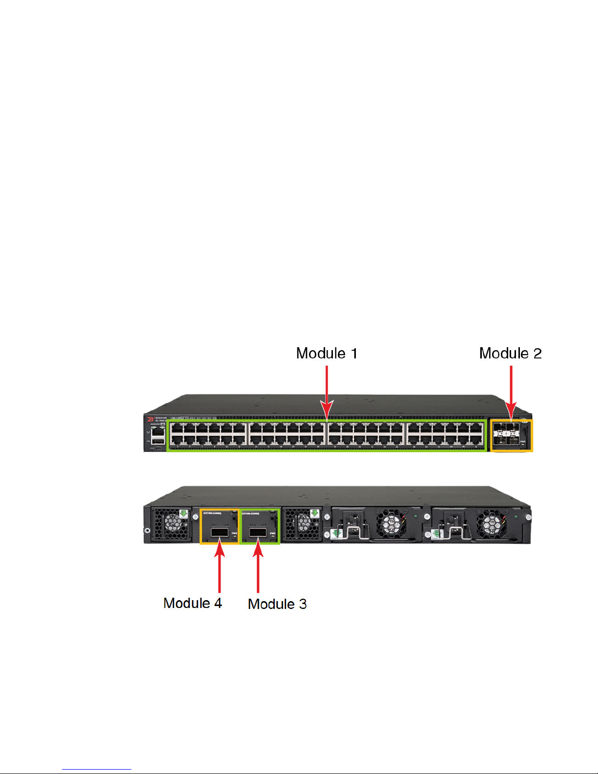
The Brocade ICX 7450 has five different models based on Port Density, PoE capability and Port type;
in addition each of the SKU supports four different flex modules. The SKU types are as follows:
1. ICX7450-24
2. ICX7450-24P
3. ICX7450-48
4. ICX7450-48P
5. ICX7450-48F
The different flexible modules are as follows:
1. 4x10F SFP+
2. 4x10T Copper
3. 1x40Q Fiber
4. 4X1F Fiber
FIGURE 1 Brocade ICX 7450 front and back panel showing Module 1 through 4
6 Brocade ICX 7450, Brocade ICX 7750, and Brocade ICX 7250 Stacking Deployment Guide
53-1003581-03
Page 7
Part
Number
Flex module support in different slotsTABLE 1
Ports
Brocade ICX 7450, Brocade ICX 7750, and Brocade ICX 7250 Stacking
ICX7450-24
ICX7450-24 P
ICX7450-48
ICX7450-48P
ICX7450-48F
ICX7400-4X
1GF
ICX7400-4X
10GF
ICX7400-4X
10GC
ICX7400-1X
40GQ
4-port
100M/1G
SFP
4-port
1/10G SFP
+
4-port
1/10G
10GBaseT
Copper
1-port 40G
QSFP+
Module 2
Front
Uplink No No Uplink No No
Uplink Uplink Uplink Uplink Uplink Uplink
Uplink Uplink Uplink Uplink Uplink Uplink
Uplink Uplink or
Module 3
Rear
stacking
Module 4
Rear
Uplink or
stacking
Module 2
Front
No Uplink or
Module 3
Rear
stacking
Module 3
Rear
Uplink or
stacking
ICX7450-24
This is a fixed 24-Port RJ45 10/100/1000Mbps Ethernet port platform and it is EEE hardware ready. It
has a full wide hot-plug module slot in the front and two full wide hot-plug module slots in the back.
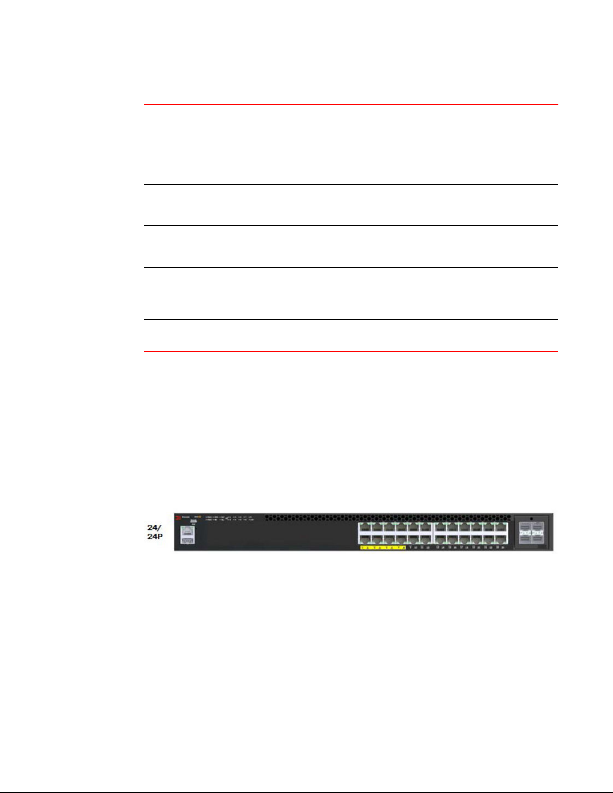
ICX7450-24P
This is a fixed 24-Port RJ45 10/100/1000Mbps Ethernet port platform with EEE hardware ready and
PoE support. The SKU supports PoE (15.4 W) and PoE+ (25.5 W) on all the ports while Cisco's
proprietary uPoE (60W)and HDBase-T alliance's PoH (up to 95W) support is provided in the first eight
ports. It has full wide hot-plug module slot in the front and two full wide hot-plug module slots in the
back.
FIGURE 2 ICX 7450-24P Front Panel
ICX7450-48
This is a fixed 48-Port RJ45 10/100/1000Mbps Ethernet port platform that is EEE hardware ready. It has
a full wide hot-plug module slot in the front and two full wide hot-plug module slots in the back.
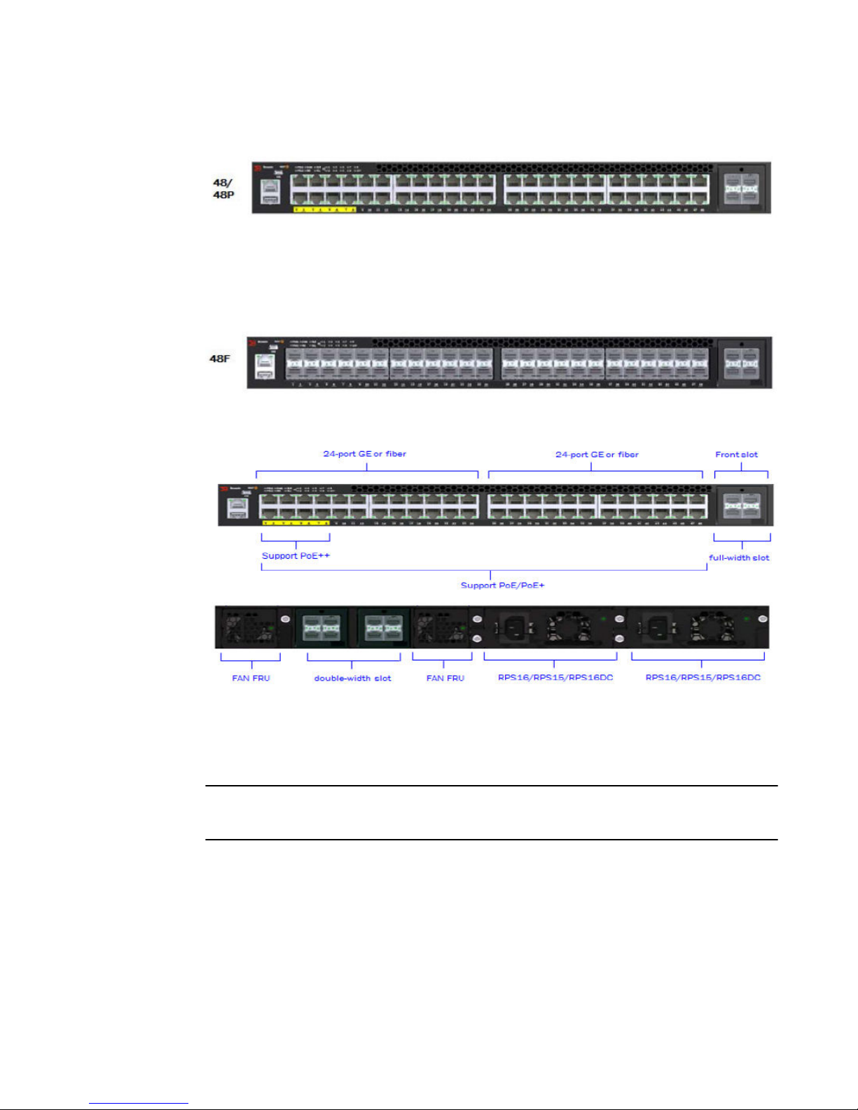
ICX7450-48P
This is a fixed 48-Port RJ45 10/100/1000Mbps Ethernet port platform with EEE hardware ready and
PoE support. The SKU supports PoE (15.4 W) and PoE+ (25.5 W) on all the ports, while Cisco's
proprietary uPoE (60 W) and HDBase-T alliance's PoH (up to 95W) support is provided in the first eight
ports. It has full wide hot-plug module slot in the front and two full wide hot-plug module slots in the
back.
Brocade ICX 7450, Brocade ICX 7750, and Brocade ICX 7250 Stacking Deployment Guide 7
53-1003581-03
Page 8
Brocade ICX 7450, Brocade ICX 7750, and Brocade ICX 7250 Stacking
FIGURE 3 ICX 7450-48P Front Panel
ICX7450-48F
This is a fixed 48-Port 1GB Ethernet SFP. It has a full wide hot-plug module slot in the front and two
full wide hot-plug module slots in the back.
FIGURE 4 ICX 7450-48P Front Panel
FIGURE 5 ICX 7450-48P Front Panel
ICX 7450 Stacking
With Release 08.0.20, the Brocade ICX 7450 supported stacking only on 1x40G modules. With
Release 08.0.30, the Brocade ICX 7450 supports stacking on 4x10G modules as well.
NOTE
The ICX 7450 can support 4X10 GF stacking from slot 2 or 1x40GQ stacking from rear ports;
however, it cannot support both in the same stack.
ICX Stacking with 1x40G Ports
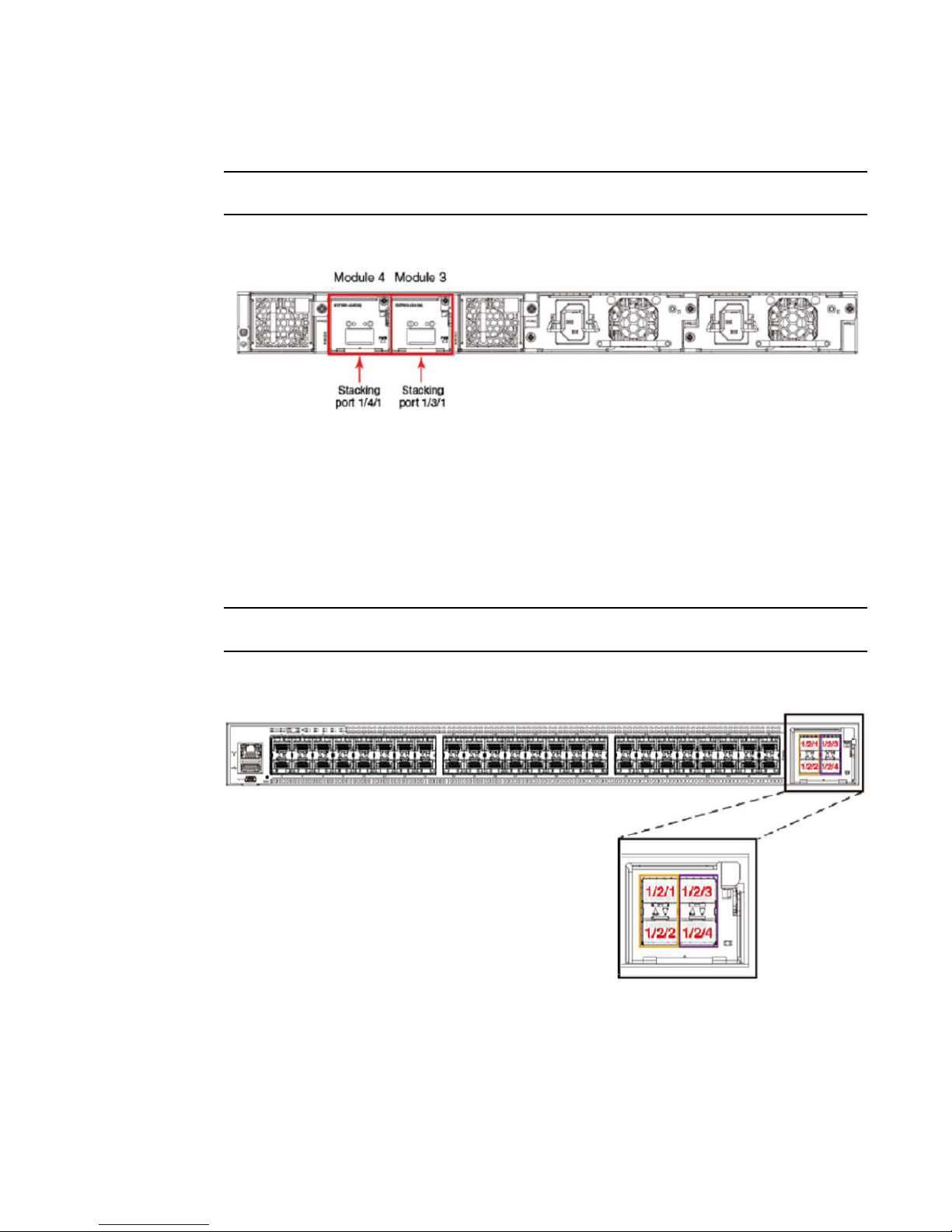
Stacking is supported only on 1x40Q module when placed in rear modules 3 and 4 for 24 ports and 48
port SKUs. For 24 port units, 1x40Q module is supported in all three flexible module slots which are
Modules 2, 3 and 4; but it will not support stacking when present in slot 1. For 48 port units, 1x40Q
module is supported only on slots 2 and 3. Please refer to Table 1 for more details.
When stacking enabled, the two stack ports configured by default are 1/3/1 and 1/4/1. The following
figure shows default stacking ports for ICX7450.
8 Brocade ICX 7450, Brocade ICX 7750, and Brocade ICX 7250 Stacking Deployment Guide
53-1003581-03
Page 9
Brocade ICX 7450, Brocade ICX 7750, and Brocade ICX 7250 Stacking
NOTE
When stacking is not enabled, ports x/3/1 and x/4/1 can be used as data/uplink ports.
FIGURE 6 ICX 7450 Showing 1x40G Stacking Ports
ICX Stacking with 4x10G Ports
Stacking is supported on 4x10GF modules when placed in front module 2 for 24 ports and 48 port
SKUs. 4x10GF module can be supported in slot 3 and 4 of all SKUs but stacking on 4x10GF module is
supported only when present in module 2. Please refer to Table 1 for more details.
Since default stacking ports are 1/3/1 and 1/4/1, user has to use "default-ports 1/2/1 1/2/3" command to
change default stacking ports to 4x10GF ports. With 4x10GF ports, comes support for stack trunks.
Trunk can be x/2/1 to x/2/2 and x/2/3 to x/2/4. Each trunk must have a default stacking port configured
as first trunk port. The figure below shows 4x10GF ports available for stacking.
NOTE
When stacking is not enabled, ports x/2/1 and x/2/3 can be used as data/uplink ports.
FIGURE 7 ICX 7450 Showing 4x10G Stacking Ports
Stack can be formed using up to 12 units of any ICX 7450 model type as a liner topology or a ring
topology.
Brocade ICX 7450, Brocade ICX 7750, and Brocade ICX 7250 Stacking Deployment Guide 9
53-1003581-03
Page 10
Supported Topologies
Supported Topologies
The Brocade ICX 7450 can operate as a standalone device as well as a stackable device. When used
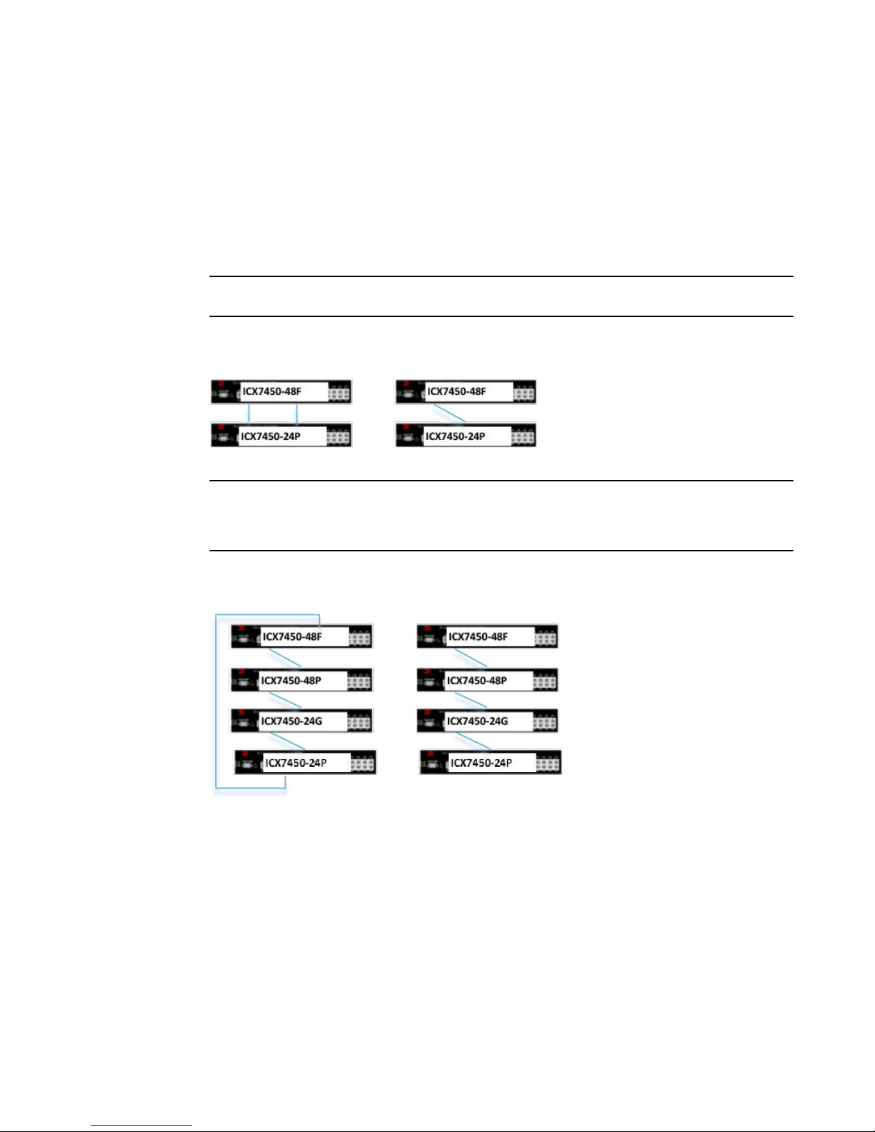
as a stack, ICX 7450 supports linear and ring stack topologies. All different SKUs of ICX 7450 can be
mixed in the same stack. The stack can be formed with two units and up to twelve units. Following are
examples of some of the ICX 7450 stacks connected in linear and ring topologies using 1x40G
stacking ports.
NOTE
The Brocade ICX 7450 cannot be combined in a stack with other Brocade stackable devices.
2 unit stack linear and ring topology
NOTE
The Brocade ICX 7450 does not support trunking on 1x40G stack ports. For the two unit ring topology
shown above, the stack ports x/3/1 and x/4/1 on each unit cannot be used to form one trunk; they
should be individual stacking ports.
4 unit stack linear and ring topology
10 Brocade ICX 7450, Brocade ICX 7750, and Brocade ICX 7250 Stacking Deployment Guide
53-1003581-03
Page 11

8 unit stack linear and ring topology
8 unit stack linear and ring topology
Brocade ICX 7450, Brocade ICX 7750, and Brocade ICX 7250 Stacking Deployment Guide 11
53-1003581-03
Page 12
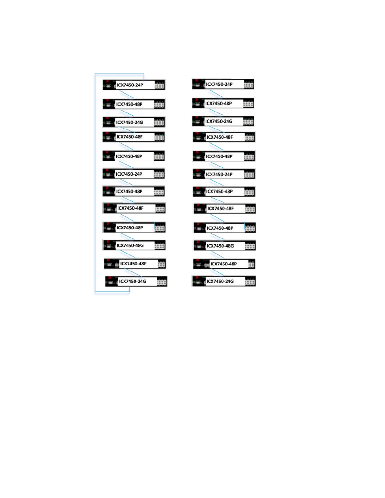
12 unit stack linear and ring topology
12 unit stack linear and ring topology
Brocade ICX 7450 Stack Construction Methods with 1x40G Stacking
Ports
Two ways of constructing a stack are as follows:
1. Use the 'secure setup' utility to form the stack.
2. Manual stack formation where each unit is configured individually.
Topology
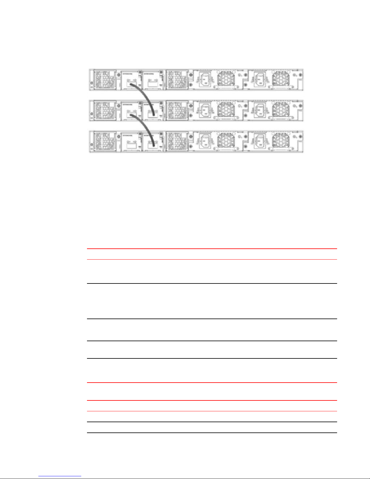
The figure below shows the rear view of the three units connected in a linear topology. Similarly a
stack of up to 12 units can be connected. The example presented here for configuration is for 12 unit
stack. Please refer to the Bill of Materials section later in this document for the software image, optics,
and vendor information
12 Brocade ICX 7450, Brocade ICX 7750, and Brocade ICX 7250 Stacking Deployment Guide
53-1003581-03
Page 13
Brocade ICX 7450, Brocade ICX 7750, and Brocade ICX 7250 Stacking
FIGURE 8 Brocade ICX 7450: Three unit stack connected in linear topology
Prerequisites
1. All 12 units have 1x40G module present in slots 3 and 4 each.
2. Connect 12 units in a linear topology using port 1/3/1 and 1/4/1 on each unit.
3. All units should be booted up with same software image.
Bill of Materials
The products listed in the tables below are used in this deployment.
Products used in the Brocade ICX7450 stackingTABLE 2
Identifier Vendor Model Notes
Switch/Units Brocade ICX7450-24G, ICX7450-24P,
ICX7450-48G, ICX7450-48P,
ICX7450-48F
Stacking cable:
Copper option
Stacking optics: Fiberoptic options
Application Image FI08.0.20 or later release NA All units should have same
License needed for
stacking
Refer to Table 3
Refer to Table 3
NA NA License is not needed for
• (1) 0.5, 1-meter QSFP-QSFP
passive copper
• 1,3, 5-meter QSFP-QSFP
active copper
• 40G-QSFP-SR4
• 40G-QSFP-LR4
Stack can be formed with
mix and match of all 5
different SKUs listed
NA
Fiber optic maximum
distance is 100 M
software image
1x40G ports to configure
stacking
Optics information for the Brocade ICX7450 stackingTABLE 3
QSFP Hardware Description BRCD Part Number
40G-QSFP-SR4 40GE SR 57-1000128-01
40G-QSFP-SR4 40GE SR 57-1000128-01
Brocade ICX 7450, Brocade ICX 7750, and Brocade ICX 7250 Stacking Deployment Guide 13
53-1003581-03
Page 14

Stack construction method 1: Stack secure setup
Optics information for the Brocade ICX7450 stacking (Continued)TABLE 3
QSFP Hardware Description BRCD Part Number
40G-QSFP-LR4 40GE LR 57-1000263-01
40G-QSFP-LR4 40GE LR 57-1000263-01
40G-QSFP-C-00501 40GE QSFP to QSFP 0.5M
Cable(Passive)
40G-QSFP-C-00501 40GE QSFP to QSFP 0.5M
Cable(Passive)
40G-QSFP-C-00501 40GE QSFP to QSFP 0.5M
Cable(Passive)
40G-QSFP-C-0101 40GE QSFP to QSFP 1M
Cable(Passive)
40G-QSFP-C-0101 40GE QSFP to QSFP 1M
Cable(Passive)
40G-QSFP-QSFP-C-0101 40GE QSFP Active Copper 1m 58-0000041-01
40G-QSFP-QSFP-C-0101 40GE QSFP Active Copper 1m 58-0000041-01
40G-QSFP-QSFP-C-0301 40GE QSFP Active Copper 3m 58-0000042-01
40G-QSFP-QSFP-C-0301 40GE QSFP Active Copper 3m 58-0000042-01
40G-QSFP-QSFP-C-0501 40GE QSFP Active Copper 5m 58-0000043-01
40G-QSFP-QSFP-C-0501 40GE QSFP Active Copper 5m 58-0000043-01
58-0000056-01
58-0000056-01
58-0000056-01
58-0000033-01
58-0000033-01
Stack construction method 1: Stack secure setup
Description
'Stack secure setup' utility is the most convenient of all methods to form a stack. This utility uses a
Brocade proprietary discovery protocol that discovers units that are connected upstream and
downstream from the switch where this command is entered, the intended Active controller.
Steps
Stack formation with secure setup utility:
• Configure 'stack enable' on the intended active controller unit at configuration level.
• Enter 'stack secure setup' on the intended active controller unit at device level.
Detailed steps:
1. Select a unit that you want to become an active controller. Configure 'stack enable' at configuration
level as seen in the following logs.
ICX7450-24 Router#configure terminal
ICX7450-24 Router(config)#stack enable
Enable stacking. This unit actively participates in stacking
stacking is enable. optical monitoring for stacking ports 1/3/1, 1/4/1 is not
available.
ICX7450-24 Router(config)#
2. Once stack enable is configured, this command will configure two default stack ports, 1/3/1 and
1/4/1 as seen in the message displayed. This can be confirmed using 'show run' command.
ICX7450-24 Switch(config)#show running
Current configuration:
!
ver 08.0.20T213
14 Brocade ICX 7450, Brocade ICX 7750, and Brocade ICX 7250 Stacking Deployment Guide
53-1003581-03
Page 15

Brocade ICX 7450, Brocade ICX 7750, and Brocade ICX 7250 Stacking
!
stack unit 1
module 1 icx7450-24-port-management-module
module 2 icx7400-xgf-4port-40g-module
module 3 icx7400-qsfp-1port-40g-module
module 4 icx7400-qsfp-1port-40g-module
stack-port 1/3/1 1/4/1
stack enable
stack mac cc4e.246c.e100
!
!!
3. Enter 'stack secure setup 'at device level, this command triggers a Brocade proprietary discovery
protocol that begins the discovery process in both upstream and downstream directions. The
discovery process produces a list of upstream and downstream devices that are available to join the
stack. This process will assign switch IDs to the units. During stack formation user will be prompted
to enter desired number of units either upstream or downstream depending on the connections. In
the following example 11 units are discovered downstream.
NOTE
During the secure-setup process, after one minute of inactivity, authentication for stack members
expires, forcing you to restart the process .
NOTE
To exit the secure-setup, enter Control-C (^C) at any time.
ICX7450-24 Router(config)#exit
ICX7450-24 Router#
ICX7450-24 Router# stack secure-setup
ICX7450-24 Router# Discovering the stack topology...
TFTP session timed out
Available DOWNSTREAM units
Hop(s) Id Type Mac Address
1 new ICX7450-48G cc4e.246d.1c78
2 new ICX7450-48G cc4e.246d.1b78
3 new ICX7450-48G cc4e.246d.1df8
4 new ICX7450-48P cc4e.2489.8640
5 new ICX7450-48GF cc4e.246d.1478
6 new ICX7450-48P cc4e.2489.b388
7 new ICX7450-48P cc4e.2489.b188
8 new ICX7450-48P cc4e.246d.2938
9 new ICX7450-48G cc4e.246d.1838
10 new ICX7450-48P cc4e.246d.23b8
11 new ICX7450-24P cc4e.246d.0520
Enter the number of the desired DOWNSTREAM units (0-11)[0]: 11
Selected Topology:
Active Id Type Mac Address
1 ICX7450-24G cc4e.246c.ffd0
Selected DOWNSTREAM units
Hop(s) Id Type Mac Address
1 2 ICX7450-48G cc4e.246d.1c78
2 3 ICX7450-48G cc4e.246d.1b78
3 4 ICX7450-48G cc4e.246d.1df8
4 5 ICX7450-48P cc4e.2489.8640
5 6 ICX7450-48GF cc4e.246d.1478
6 7 ICX7450-48P cc4e.2489.b388
7 8 ICX7450-48P cc4e.2489.b188
8 9 ICX7450-48P cc4e.246d.2938
9 10 ICX7450-48G cc4e.246d.1838
10 11 ICX7450-48P cc4e.246d.23b8
11 12 ICX7450-24P cc4e.246d.0520
4. The user is prompted to enter 'y' to confirm unit IDs. If the user wants to enter different unit IDs, the
user should enter 'n' instead of 'y.' This example log shows 'y' because acceptance was entered.
Brocade ICX 7450, Brocade ICX 7750, and Brocade ICX 7250 Stacking Deployment Guide 15
53-1003581-03
Page 16

Brocade ICX 7450, Brocade ICX 7750, and Brocade ICX 7250 Stacking
Once stack switch IDs are accepted, the stack units, except the active controller, reset so that the
assigned IDs become effective. By default active unit is assigned priority 128 with secure setup
utility.
Do you accept the unit id's (y/n)?: y
ICX7450-24 Router# TFTP session timed out
T=1m50.1: Election, was alone --> active, ID=1, pri=128, 12U(1-12), A=u1, nbr#=0
11, reason: u12: port-up, ,
T=1m53.2: reset unit 2: u2 bo-id=1
T=1m53.2: reset unit 3: u3 bo-id=1
T=1m53.2: reset unit 4: u4 bo-id=1
T=1m53.2: reset unit 5: u5 bo-id=1
T=1m53.2: reset unit 6: u6 bo-id=1
T=1m53.2: reset unit 7: u7 bo-id=1
T=1m53.2: reset unit 8: u8 bo-id=1
T=1m53.2: reset unit 9: u9 bo-id=1
T=1m53.2: reset unit 10: u10 bo-id=1
T=1m53.2: reset unit 11: u11 bo-id=1
T=1m53.2: reset unit 12: u12 bo-id=1
Config changed due to add/del units. Do write mem if you want to keep it
T=1m56.3: Unit 1 loses all neighbors.
T=1m56.7: Active U1 deletes U2 and its config because it is learned.
T=1m57.1: Active U1 deletes U3 and its config because it is learned.
T=1m57.5: Active U1 deletes U4 and its config because it is learned.
T=1m57.8: Active U1 deletes U5 and its config because it is learned.
T=1m57.8: Active U1 deletes U6 and its config because it is learned.
T=1m57.9: Active U1 deletes U7 and its config because it is learned.
T=1m57.9: Active U1 deletes U8 and its config because it is learned.
T=1m57.9: Active U1 deletes U9 and its config because it is learned.
T=1m57.9: Active U1 deletes U10 and its config because it is learned.
T=1m58.0: Active U1 deletes U11 and its config because it is learned.
T=1m58.0: Active U1 deletes U12 and its config because it is learned.
T=4m17.7: Election, was active, no change, ID=1, pri=128, 12U(1-12), A=u1, nbr#=0
11,
reason: u12: port-up, ,
5. Various settings and files are synced from the master to the newly joined units.
T=4m19.1: Synchronize webauth files to u7
T=4m19.1: Synchronize webauth files to u8
T=4m19.1: Synchronize webauth files to u9
Detect stack member 7 POE capable
Detect stack member 8 POE capable
Detect stack member 9 POE capable
T=4m19.4: Synchronize webauth files to u2
T=4m19.4: Synchronize webauth files to u3
T=4m19.5: Synchronize webauth files to u4
T=4m19.5: Synchronize webauth files to u5
Detect stack member 5 POE capable
T=4m19.6: Synchronize webauth files to u6
T=4m20.3: Synchronize webauth files to u10
T=4m20.3: Synchronize webauth files to u11
T=4m20.3: Synchronize webauth files to u12
6. While stack formation, units go through various stages when they joins the stack. Once units
become part of the stack and the master syncs relevant information and files to all the units and
then they are set in "READY" state. During the process the user is prompted to 'write memory' to
save changes.
Detect stack member 11 POE capable
Detect stack member 12 POE capable
T:4m20.6: Done hot swap: active controller u1 sets u7 to Ready.
T:4m20.7: Done hot swap: active controller u1 sets u8 to Ready.
T:4m20.9: Done hot swap: active controller u1 sets u9 to Ready.
T:4m21.1: Done hot swap: active controller u1 sets u2 to Ready.
T:4m21.4: Done hot swap: active controller u1 sets u3 to Ready.
T:4m21.6: Done hot swap: active controller u1 sets u4 to Ready.
T:4m21.8: Done hot swap: active controller u1 sets u5 to Ready.
T:4m22.3: Done hot swap: active controller u1 sets u6 to Ready.
Stack unit 4 Power supply 1 is up
Stack unit 4 Power supply 2 is down
Stack unit 8 Power supply 1 is down
PoE: Stack unit 8 Power supply 2 with 748000 mwatts capacity is up
Config changed due to add/del units. Do write mem if you want to keep it
Stack unit 7 Power supply 1 is down
PoE: Stack unit 7 Power supply 2 with 748000 mwatts capacity is up
T:4m24.0: Done hot swap: active controller u1 sets u10 to Ready.
T:4m25.5: Done hot swap: active controller u1 sets u11 to Ready.
16 Brocade ICX 7450, Brocade ICX 7750, and Brocade ICX 7250 Stacking Deployment Guide
53-1003581-03
Page 17

Stack construction method 2: Manual configuration
T=4m25.5: Election, was active, no change, ID=1, pri=128, 12U(1-12), A=u1, nbr#=0
11, reason: u1: stk-po-chg, ,
T:4m26.5: Done hot swap: active controller u1 sets u12 to Ready.
Stack unit 3 Power supply 1 is up
Stack unit 3 Power supply 2 is down
Stack unit 10 Power supply 1 is up
Stack unit 10 Power supply 2 is down
Stack unit 2 Power supply 1 is up
Stack unit 2 Power supply 2 is down
PoE: Stack unit 12 Power supply 1 with 258000 mwatts capacity is up
PoE: Stack unit 12 Power supply 2 with 258000 mwatts capacity is up
PoE: Stack unit 5 Power supply 1 with 748000 mwatts capacity is up
Stack unit 5 Power supply 2 is down
PoE: Stack unit 9 Power supply 1 with 748000 mwatts capacity is up
Stack unit 9 Power supply 2 is down
Stack unit 6 Power supply 1 is up
Stack unit 6 Power supply 2 is down
PoE: Stack unit 11 Power supply 1 with 748000 mwatts capacity is up
Stack unit 11 Power supply 2 is down
Config changed due to add/del units. Do write mem if you want to keep it
T=5m27.4: Assigned unit 2 to be standby
T=5m29.4: start running config sync to standby u2
T=5m30.1: Running config sync to standby u2 is complete
7. Upon booting up of the stack units is complete, stack formation is complete as units are set 'Ready'.
Stack status can be verified using 'show stack' command. In this output, D indicates a dynamic
configuration. After user enters a write memory, this display will change to S, for static configuration.
ICX7450-24 Router#show stack
T=8m39.6: alone: standalone, D: dynamic cfg, S: static, A=10, B=11, C=12
ID Type Role Mac Address Pri State Comment
1 S ICX7450-24G active cc4e.246c.ffd0 128 local Ready
2 D ICX7450-48G standby cc4e.246d.1c78 0 remote Ready
3 D ICX7450-48G member cc4e.246d.1b78 0 remote Ready
4 D ICX7450-48G member cc4e.246d.1df8 0 remote Ready
5 D ICX7450-48P member cc4e.2489.8640 0 remote Ready
6 D ICX7450-48GF member cc4e.246d.1478 0 remote Ready
7 D ICX7450-48P member cc4e.2489.b388 0 remote Ready
8 D ICX7450-48P member cc4e.2489.b188 0 remote Ready
9 D ICX7450-48P member cc4e.246d.2938 0 remote Ready
10 D ICX7450-48G member cc4e.246d.1838 0 remote Ready
11 D ICX7450-48P member cc4e.246d.23b8 0 remote Ready
12 D ICX7450-24P member cc4e.246d.0520 0 remote Ready
active standby
+---+ +---+ +---+ +---+ +---+ +---+
3/1| 1 |4/1--3/1| 2 |4/1--3/1| 3 |4/1--3/1| 4 |4/1--3/1| 5 |4/1--3/1| 6 |4/1 +---+ +---+ +---+ +---+ +---+ +---+ |
|
|
+---+ +---+ +---+ +---+ +---+ +---+ |
| C |3/1--4/1| B |3/1--4/1| A |3/1--4/1| 9 |3/1--4/1| 8 |3/1--4/1| 7 |3/1 +---+ +---+ +---+ +---+ +---+ +---+
Standby u2 - protocols ready, can failover
Current stack management MAC is cc4e.246c.ffd0
ICX7450-24 Router#
Stack construction method 2: Manual configuration
Description
With this method, user should configure every unit individually and enable stacking on each unit. Once
the units are connected together, they automatically form a stack. With this method, the unit with the
highest priority becomes the active controller, and ID assignment is determined by the sequence in
which user physically connects the units. The example used below is 12 units to form a linear stack.
Steps
Manual stack formation:
• Configure the highest priority on an intended active controller.
• Configure second highest priority on an intended standby controller.
Brocade ICX 7450, Brocade ICX 7750, and Brocade ICX 7250 Stacking Deployment Guide 17
53-1003581-03
Page 18

Brocade ICX 7450, Brocade ICX 7750, and Brocade ICX 7250 Stacking
• Configure 'stack suggested-id' on the units that will have a desired ID.
• Configure 'stack enable' on all the units and connect the units using stack ports.
Detailed steps
1. Units should boot up using the same software image.
2. On the unit that is intended to be the active controller, configure priority 255. On the unit intended to
be on standby, configure priority 240. User can choose to have the same priority for active and
standby, which is useful in case of failover.
3. Since each unit is a clean unit, its unit id is 1. Enter 'configure terminal', enter 'stack unit 1' and
configure 'stack suggested-id' on all the units that will have the desired ID.
4. Configure 'stack enable' on all the units.
UNIT 1:
ICX7450-24 Router(config)#stack unit 1
ICX7450-24 Router(config-unit-1)#priority 255
ICX7450-24 Router(config-unit-1)#stack enable
Enable stacking. This unit actively participates in stacking
stacking is enable. optical monitoring for stacking ports 1/3/1, 1/4/1 is not
available.
ICX7450-24 Router(config-unit-1)#
UNIT 2:
ICX7450-48 Router(config)#stack unit 1
ICX7450-48 Router(config-unit-1)#priority 240
ICX7450-48 Router(config-unit-1)#stack suggested-id 2
ICX7450-48 Router(config-unit-1)#stack enable
Enable stacking. This unit actively participates in stacking
stacking is enable. optical monitoring for stacking ports 1/3/1, 1/4/1 is not
available.
ICX7450-48 Router(config-unit-1)#
UNIT 3:
ICX7450-48 Router(config-unit-1)#stack suggested-id 3
ICX7450-48 Router(config-unit-1)#stack enable
Enable stacking. This unit actively participates in stacking
stacking is enable. optical monitoring for stacking ports 1/3/1, 1/4/1 is not
available.
ICX7450-48 Router(config-unit-1)#
UNIT 4:
ICX7450-48 Router(config)#stack unit 1
ICX7450-48 Router(config-unit-1)#stack suggested-id 4
ICX7450-48 Router(config-unit-1)#stack enable
Enable stacking. This unit actively participates in stacking
stacking is enable. optical monitoring for stacking ports 1/3/1, 1/4/1 is not
available.
ICX7450-48 Router(config-unit-1)#
UNIT 5
ICX7450-48P Router(config)#stack unit 1
ICX7450-48P Router(config-unit-1)#stack suggested-id 5
ICX7450-48P Router(config-unit-1)#stack enable
Enable stacking. This unit actively participates in stacking
stacking is enable. optical monitoring for stacking ports 1/3/1, 1/4/1 is not
available.
ICX7450-48P Router(config-unit-1)#
UNIT 6:
ICX7450-48F Router(config)#stack unit 1
ICX7450-48F Router(config-unit-1)#stack suggested-id 6
ICX7450-48F Router(config-unit-1)#stack enable
Enable stacking. This unit actively participates in stacking
stacking is enable. optical monitoring for stacking ports 1/3/1, 1/4/1 is not
available.
ICX7450-48F Router(config-unit-1)#
UNIT 7:
ICX7450-48P Router(config)#stack unit 1
18 Brocade ICX 7450, Brocade ICX 7750, and Brocade ICX 7250 Stacking Deployment Guide
53-1003581-03
Page 19

Brocade ICX 7450, Brocade ICX 7750, and Brocade ICX 7250 Stacking
ICX7450-48P Router(config-unit-1)#stack suggested-id 7
ICX7450-48P Router(config-unit-1)#stack enable
Enable stacking. This unit actively participates in stacking
stacking is enable. optical monitoring for stacking ports 1/3/1, 1/4/1 is not
available.
ICX7450-48P Router(config-unit-1)#
UNIT 8:
ICX7450-48P Router(config)#stack unit 1
ICX7450-48P Router(config-unit-1)#stack suggested-id 8
ICX7450-48P Router(config-unit-1)#stack enable
Enable stacking. This unit actively participates in stacking
stacking is enable. optical monitoring for stacking ports 1/3/1, 1/4/1 is not
available.
ICX7450-48P Router(config-unit-1)#
UNIT 9:
ICX7450-48P Router(config)#stack unit 1
ICX7450-48P Router(config-unit-1)#stack suggested-id 9
ICX7450-48P Router(config-unit-1)#stack enable
Enable stacking. This unit actively participates in stacking
stacking is enable. optical monitoring for stacking ports 1/3/1, 1/4/1 is not
available.
ICX7450-48P Router(config-unit-1)#
UNIT 10:
ICX7450-48 Router(config)#stack unit 1
ICX7450-48 Router(config-unit-1)#stack suggested-id 10
ICX7450-48 Router(config-unit-1)#stack enable
Enable stacking. This unit actively participates in stacking
stacking is enable. optical monitoring for stacking ports 1/3/1, 1/4/1 is not
available.
ICX7450-48 Router(config-unit-1)#
UNIT 11:
ICX7450-48P Router(config)#stack unit 1
ICX7450-48P Router(config-unit-1)#stack suggested-id 11
ICX7450-48P Router(config-unit-1)#stack enable
Enable stacking. This unit actively participates in stacking
stacking is enable. optical monitoring for stacking ports 1/3/1, 1/4/1 is not
available.
ICX7450-48P Router(config-unit-1)#
UNIT 12:
ICX7450-24P Router(config)#stack unit 1
ICX7450-24P Router(config-unit-1)# stack suggested-id 12
ICX7450-24P Router(config-unit-1)#stack enable
Enable stacking. This unit actively participates in stacking
stacking is enable. optical monitoring for stacking ports 1/3/1, 1/4/1 is not
available.
ICX7450-24P Router(config-unit-1)#
5. After configuration, connect the devices in a stack topology. The active controller retains its ID. The
rest of the units are assigned unique ID numbers depending on the sequence in which they are
connected or depending on the stack suggest-ID configured. With the exception of the active
controller, the rest of the units reset; upon boot up, the stack is formed.
ICX7450-24 Router#show stack
T=8m39.6: alone: standalone, D: dynamic cfg, S: static, A=10, B=11, C=12
ID Type Role Mac Address Pri State Comment
1 S ICX7450-24G active cc4e.246c.ffd0 128 local Ready
2 D ICX7450-48G standby cc4e.246d.1c78 0 remote Ready
3 D ICX7450-48G member cc4e.246d.1b78 0 remote Ready
4 D ICX7450-48G member cc4e.246d.1df8 0 remote Ready
5 D ICX7450-48P member cc4e.2489.8640 0 remote Ready
6 D ICX7450-48GF member cc4e.246d.1478 0 remote Ready
7 D ICX7450-48P member cc4e.2489.b388 0 remote Ready
8 D ICX7450-48P member cc4e.2489.b188 0 remote Ready
9 D ICX7450-48P member cc4e.246d.2938 0 remote Ready
10 D ICX7450-48G member cc4e.246d.1838 0 remote Ready
11 D ICX7450-48P member cc4e.246d.23b8 0 remote Ready
12 D ICX7450-24P member cc4e.246d.0520 0 remote Ready
active standby
Brocade ICX 7450, Brocade ICX 7750, and Brocade ICX 7250 Stacking Deployment Guide 19
53-1003581-03
Page 20
Brocade ICX 7450 Stack Construction Methods with 4x10G Stacking Ports
+---+ +---+ +---+ +---+ +---+ +---+
3/1| 1 |4/1--3/1| 2 |4/1--3/1| 3 |4/1--3/1| 4 |4/1--3/1| 5 |4/1--3/1| 6 |4/1 +---+ +---+ +---+ +---+ +---+ +---+ |
|
|
+---+ +---+ +---+ +---+ +---+ +---+ |
4/1| C |3/1--4/1| B |3/1--4/1| A |3/1--4/1| 9 |3/1--4/1| 8 |3/1--4/1| 7 |3/1 +---+ +---+ +---+ +---+ +---+ +---+
Standby u2 - protocols ready, can failover
Current stack management MAC is cc4e.246c.ffd0
ICX7450-24 Router#
Brocade ICX 7450 Stack Construction Methods with 4x10G Stacking
Ports
Two ways of constructing a stack are as follows:
1. Use the 'secure setup' utility to form the stack.
2. Manual stack formation where each unit is configured individually.
Topology
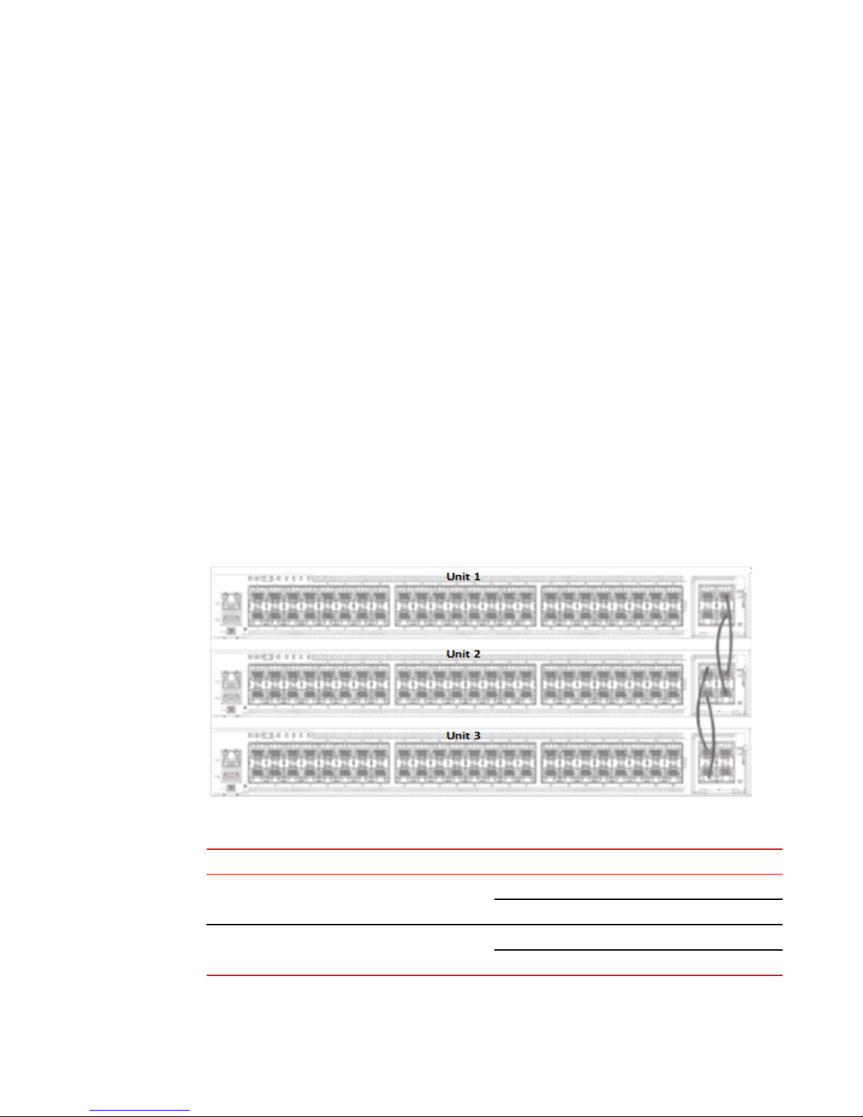
The figure below shows the rear of three units connected in a linear topology using stack trunks.
Similarly, a stack of up to 12 units can be connected. The example presented here for configuration is
for a 12-unit stack. Please refer to Bill of Materials, table 2 and table 3 for the software image, optics
and vendor information.
FIGURE 9 Brocade ICX 7450 three unit stack connected in linear topology using 4x10G stacking ports
Stacking connections in Brocade ICX 7450 three unit stack TABLE 4
Units Links/Trunks
Unit1 to Unit2 1/2/3 to 2/2/3
Unit2 to Unit3 2/2/1 to 3/2/1
20 Brocade ICX 7450, Brocade ICX 7750, and Brocade ICX 7250 Stacking Deployment Guide
1/2/4 to 2/2/4
2/2/2 to 3/2/2
53-1003581-03
Page 21

Stack construction method 1: Stack secure setup
Prerequisites
1. All 12 units have 4x10GF module present in slot 2.
2. Connect 12 units in a linear topology using stack trunks 1/2/1 to 1/2/2 and 1/2/3 to 1/2/4 on each unit.
Please connect as seen in Figure 9 .
3. All units should be booted up with same software image.
Bill of Materials
Products used in Brocade ICX 7450 4x10G StackingTABLE 5
Identifier Vendor Model Notes
Switch/Units Brocade ICX7450-24G,
ICX7450-24P,
ICX7450-48G,
ICX7450-48P,
ICX7450-48F
Stacking optics: Fiber-optic
options
Application image FI08.0.30 or later release NA All units should have the
License needed for
stacking
Refer to Table 6
NA NA License is not needed for
1. 100M USR OM3
2. 300M SR MM OM3 LC
3. 10KM 10G SFPP LR
Stack can be formed with
mix and match of all five
different SKUs listed.
Fiber optic maximum
distance is 10KM
same software image
1x40G ports to configure
stacking
Optics information for Brocade ICX 7450 StackingTABLE 6
SFP+ Hardware Description BRCD Part Number
10GE LR 10km (SFP +) 10GE LR 10km (SFP +) 57-0000076-01
10GE SR 300m (SFP +) 10GE SR 300m (SFP +) 57-0000075-01
10GE USR 100m (SFP +) 10GE USR 10km (SFP +) 57-1000130-01
Stack construction method 1: Stack secure setup
Description
'Stack secure setup' utility is the most convenient of all methods to form a stack. This utility uses a
Brocade proprietary discovery protocol that discovers units that are connected upstream and
downstream from the switch where this command is entered, the intended Active controller.
Steps
Stack formation with secure setup utility:
Brocade ICX 7450, Brocade ICX 7750, and Brocade ICX 7250 Stacking Deployment Guide 21
53-1003581-03
Page 22

Brocade ICX 7450, Brocade ICX 7750, and Brocade ICX 7250 Stacking
• Configure 'default-ports 1/2/1 1/2/3' on all the units, write memory and reload. This step is needed
because mac-sec and stacking cannot exist at the same time on a port.
• When units boot up, configure 'stack enable' on the intended active controller unit at configuration
level.
• Enter 'stack secure setup' on the intended active controller unit at device level.
Detailed Steps
1. Select a unit that you want to become an active controller. Configure 'default-ports 1/2/1 1/2/3' on all
the units, write memory and reload
ICX7450-24 Router>enable
No password has been assigned yet...
ICX7450-24 Router#con t
ICX7450-24 Router(config)#stack unit 1
ICX7450-24 Router(config-unit-1)#default-ports 1/2/1 1/2/3
Reload required. Please write memory and then reload or power cycle.
ICX7450-24 Router(config-unit-1)#
ICX7450-24 Router(config-unit-1)#end
ICX7450-24 Router#
ICX7450-24 Router#Flash Memory Write (8192 bytes per dot) .
Write startup-config done.
Copy Done.
ICX7450-24 Router#
ICX7450-24 Router#
ICX7450-24 Router#rel
Sent SIGTERM to all processesn'):
Sent SIGKILL to all processes
Requesting system reboot
Restarting system.
2. When units boot up, show run will show default ports configured as 1/2/1 1/3/1. Configure 'stack
enable' on the intended active unit.
ICX7450-24 Router#show run
Current configuration:
!
ver 08.0.30q101T213
!
stack unit 1
module 1 icx7450-24-port-management-module
module 2 icx7400-xgf-4port-40g-module
module 3 icx7400-xgf-4port-40g-module
module 4 icx7400-qsfp-1port-40g-module
default-ports 1/2/1 1/2/3
!
!
!
--More--, next page: Space, next line: Return key, quit: Control-c^C
ICX7450-24 Router#configure terminal
ICX7450-24 Router(config)#stack enable
Enable stacking. This unit actively participates in stacking
stacking is enable. optical monitoring for stacking ports 1/2/1, 1/2/3 is not
available.
ICX7450-24 Router(config)#
3. Run the 'stack secure setup' utility on the intended active unit. Since ports are connected to form
trunks, user is prompted to make a selection for desired links, enter 2 for trunks. In the following
example 11 units are discovered during stack secure setup.
ICX7450-24 Router(config)#show run
Current configuration:
!
ver 08.0.30q101T213
!
stack unit 1
module 1 icx7450-24-port-management-module
module 2 icx7400-xgf-4port-40g-module
module 3 icx7400-xgf-4port-40g-module
module 4 icx7400-qsfp-1port-40g-module
default-ports 1/2/1 1/2/3
!
!
!
--More--, next page: Space, next line: Return key, quit: Control-c^C
ICX7450-24 Router(config)#exit
ICX7450-24 Router#stack secure-setup
ICX7450-24 Router#Discovering the stack topology...
22 Brocade ICX 7450, Brocade ICX 7750, and Brocade ICX 7250 Stacking Deployment Guide
53-1003581-03
Page 23

Brocade ICX 7450, Brocade ICX 7750, and Brocade ICX 7250 Stacking
Available UPSTREAM units
Hop(s) Id Type Mac Address
1 new ICX7450-48G cc4e.246d.1c78
2 new ICX7450-48G cc4e.246d.1b78
3 new ICX7450-48G cc4e.246d.1ff8
4 new ICX7450-48P cc4e.2489.8640
5 new ICX7450-48GF cc4e.246d.1478
6 new ICX7450-48P cc4e.2489.b388
7 new ICX7450-48P cc4e.2489.b188
8 new ICX7450-48P cc4e.246d.2938
9 new ICX7450-48G cc4e.246d.1838
10 new ICX7450-48P cc4e.246d.23b8
11 new ICX7450-24P cc4e.246d.0520
Enter the number of the desired UPSTREAM units (0-11)[0]: 11
Confirm Stacking Links...
UPSTREAM Unit: Id new at 1 hop(s) ICX7450-48G cc4e.246d.1c78
Enter the desired links(1-2)[1]: 2
UPSTREAM Unit: Id new at 2 hop(s) ICX7450-48G cc4e.246d.1b78
Enter the desired links(1-2)[1]: 2
UPSTREAM Unit: Id new at 3 hop(s) ICX7450-48G cc4e.246d.1ff8
Enter the desired links(1-2)[1]: 2
UPSTREAM Unit: Id new at 4 hop(s) ICX7450-48P cc4e.2489.8640
Enter the desired links(1-2)[1]: 2
UPSTREAM Unit: Id new at 5 hop(s) ICX7450-48GF cc4e.246d.1478
Enter the desired links(1-2)[1]: 2
UPSTREAM Unit: Id new at 6 hop(s) ICX7450-48P cc4e.2489.b388
Enter the desired links(1-2)[1]: 2
UPSTREAM Unit: Id new at 7 hop(s) ICX7450-48P cc4e.2489.b188
Enter the desired links(1-2)[1]: 2
UPSTREAM Unit: Id new at 8 hop(s) ICX7450-48P cc4e.246d.2938
Enter the desired links(1-2)[1]: 2
UPSTREAM Unit: Id new at 9 hop(s) ICX7450-48G cc4e.246d.1838
Enter the desired links(1-2)[1]: 2
UPSTREAM Unit: Id new at 10 hop(s) ICX7450-48P cc4e.246d.23b8
Enter the desired links(1-2)[1]: 2
UPSTREAM Unit: Id new at 11 hop(s) ICX7450-24P cc4e.246d.0520
Enter the desired links(1-2)[1]: 2
Selected Topology:
Active Id Type Mac Address
1 ICX7450-24G cc4e.246c.ffd0
Selected UPSTREAM units
Hop(s) Id Type Mac Address
1 2 ICX7450-48G cc4e.246d.1c78
2 3 ICX7450-48G cc4e.246d.1b78
3 4 ICX7450-48G cc4e.246d.1ff8
4 5 ICX7450-48P cc4e.2489.8640
5 6 ICX7450-48GF cc4e.246d.1478
6 7 ICX7450-48P cc4e.2489.b388
7 8 ICX7450-48P cc4e.2489.b188
8 9 ICX7450-48P cc4e.246d.2938
9 10 ICX7450-48G cc4e.246d.1838
Brocade ICX 7450, Brocade ICX 7750, and Brocade ICX 7250 Stacking Deployment Guide 23
53-1003581-03
Page 24

Brocade ICX 7450, Brocade ICX 7750, and Brocade ICX 7250 Stacking
10 11 ICX7450-48P cc4e.246d.23b8
11 12 ICX7450-24P cc4e.246d.0520
Do you accept the unit id's (y/n)?: y
ICX7450-24 Router#T=5m2.9: Election, was alone --> active, ID=1, pri=128,
12U(1-12), A=u1, nbr#=11 0, reason:
u12: port-up, ,
The period is 25
T=5m6.9: Election, was active, no change, ID=1, pri=128, 12U(1-12), A=u1, nbr#=11
0, reason:
u1: stk-po-chg, ,
T=5m10.0: reset unit 2: u2 bo-id=1
T=5m10.0: reset unit 3: u3 bo-id=1
T=5m10.0: reset unit 4: u4 bo-id=1
T=5m10.0: reset unit 5: u5 bo-id=1
T=5m10.0: reset unit 6: u6 bo-id=1
T=5m10.0: reset unit 7: u7 bo-id=1
T=5m10.0: reset unit 8: u8 bo-id=1
T=5m10.0: reset unit 9: u9 bo-id=1
T=5m10.0: reset unit 10: u10 bo-id=1
T=5m10.0: reset unit 11: u11 bo-id=1
T=5m10.0: reset unit 12: u12 bo-id=1
Config changed due to add/del units. Do write mem if you want to keep it
T=5m15.0: Unit 1 loses all neighbors.
T=5m18.0: Active U1 deletes U2 and its config because it is learned.
T=5m21.0: Active U1 deletes U3 and its config because it is learned.
T=5m23.8: Active U1 deletes U4 and its config because it is learned.
T=5m26.6: Active U1 deletes U5 and its config because it is learned.
T=5m29.5: Active U1 deletes U6 and its config because it is learned.
T=5m30.5: Active U1 deletes U7 and its config because it is learned.
T=5m31.5: Active U1 deletes U8 and its config because it is learned.
T=5m32.5: Active U1 deletes U9 and its config because it is learned.
T=5m33.5: Active U1 deletes U10 and its config because it is learned.
T=5m34.5: Active U1 deletes U11 and its config because it is learned.
T=5m35.0: Active U1 deletes U12 and its config because it is learned.
T=7m5.1: Election, was active, no change, ID=1, pri=128, 3U(1-3), A=u1, nbr#=2 0,
reason: u3:
port-up, ,
NOTE
During the secure-setup process, after one minute of inactivity, authentication for stack members
expires, forcing you to restart the process.
NOTE
To exit the secure-setup, enter Control-C (^C) at any time.
4. Various settings and files are synced from the master to the newly joined units.
Detect stack unit 2 has different startup config flash, will synchronize it
T=7m5.5: Synchronize webauth files to u2
Detect stack unit 3 has different startup config flash, will synchronize it
T=7m5.5: Synchronize webauth files to u3
T:7m6.7: Done hot swap: active controller u1 sets u2 to Ready.
T:7m6.8: Done hot swap: active controller u1 sets u3 to Ready.
T=7m7.5: Synchronize startup config to u2
Flash Memory Write (8192 bytes per dot) .
Write startup-config done.
T=7m8.5: Synchronize startup config to u3
Flash Memory Write (8192 bytes per dot) .
Write startup-config done.
Stack unit 3 Power supply 1 is up
Stack unit 3 Power supply 2 is down
Stack unit 2 Power supply 1 is up
Stack unit 2 Power supply 2 is down
Config changed due to add/del units. Do write mem if you want to keep it
T=7m10.7: Election, was active, no change, ID=1, pri=128, 12U(1-12), A=u1,
nbr#=11 0,
reason: u12: port-up, ,
Detect stack unit 9 has different startup config flash, will synchronize it
T=7m11.6: Synchronize webauth files to u9
24 Brocade ICX 7450, Brocade ICX 7750, and Brocade ICX 7250 Stacking Deployment Guide
53-1003581-03
Page 25

Brocade ICX 7450, Brocade ICX 7750, and Brocade ICX 7250 Stacking
Detect stack unit 12 has different startup config flash, will synchronize it
T=7m11.6: Synchronize webauth files to u12
Detect stack member 9 POE capable
Detect stack member 12 POE capable
Detect stack unit 10 has different startup config flash, will synchronize it
T=7m11.6: Synchronize webauth files to u10
Detect stack unit 11 has different startup config flash, will synchronize it
T=7m11.6: Synchronize webauth files to u11
Detect stack unit 4 has different startup config flash, will synchronize it
T=7m11.7: Synchronize webauth files to u4
Detect stack member 11 POE capable
Detect stack unit 6 has different startup config flash, will synchronize it
T=7m11.7: Synchronize webauth files to u6
Detect stack unit 5 has different startup config flash, will synchronize it
T=7m11.7: Synchronize webauth files to u5
Detect stack unit 7 has different startup config flash, will synchronize it
T=7m11.7: Synchronize webauth files to u7
Detect stack unit 8 has different startup config flash, will synchronize it
T=7m11.7: Synchronize webauth files to u8
Detect stack member 5 POE capable
Detect stack member 7 POE capable
Detect stack member 8 POE capable
5. While stack formation, units go through various stages when they joins the stack. Once units become
part of the stack and the master syncs relevant information and files to all the units and then they are
set in "READY" state. During the process the user is prompted to 'write memory' to save changes.
T:7m12.9: Done hot swap: active controller u1 sets u9 to Ready.
T:7m13.1: Done hot swap: active controller u1 sets u10 to Ready.
T:7m13.3: Done hot swap: active controller u1 sets u11 to Ready.
T:7m13.5: Done hot swap: active controller u1 sets u12 to Ready.
T=7m13.7: Synchronize startup config to u9
T:7m13.9: Done hot swap: active controller u1 sets u4 to Ready.
Flash Memory Write (8192 bytes per dot) .
Write startup-config done.
T:7m14.0: Done hot swap: active controller u1 sets u5 to Ready.
T:7m14.2: Done hot swap: active controller u1 sets u6 to Ready.
T:7m14.7: Done hot swap: active controller u1 sets u7 to Ready.
T:7m15.2: Done hot swap: active controller u1 sets u8 to Ready.
PoE: Stack unit 9 Power supply 1 with 748000 mwatts capacity is up
Stack unit 9 Power supply 2 is down
T=7m15.7: Synchronize startup config to u4
PoE: Stack unit 5 Power supply 1 with 748000 mwatts capacity is up
Stack unit 5 Power supply 2 is down
Flash Memory Write (8192 bytes per dot) .
Write startup-config done.
Config changed due to add/del units. Do write mem if you want to keep it
PoE: Stack unit 12 Power supply 1 with 258000 mwatts capacity is up
PoE: Stack unit 12 Power supply 2 with 258000 mwatts capacity is up
Stack unit 8 Power supply 1 is down
PoE: Stack unit 8 Power supply 2 with 748000 mwatts capacity is up
T=7m16.7: Synchronize startup config to u5
Flash Memory Write (8192 bytes per dot) .
Write startup-config done.
T=7m16.8: Election, was active, no change, ID=1, pri=128, 12U(1-12), A=u1, nbr#=11
0, reason: u1: stk-po-chg, ,
T=7m17.7: Synchronize startup config to u6
Flash Memory Write (8192 bytes per dot) .
Write startup-config done.
Stack unit 10 Power supply 1 is up
Stack unit 10 Power supply 2 is down
Stack unit 7 Power supply 1 is down
PoE: Stack unit 7 Power supply 2 with 748000 mwatts capacity is up
Stack unit 11 Power supply 1 is down
PoE: Stack unit 11 Power supply 2 with 748000 mwatts capacity is up
T=7m18.7: Synchronize startup config to u7
Flash Memory Write (8192 bytes per dot) .
Write startup-config done.
T=7m19.7: Synchronize startup config to u8
Flash Memory Write (8192 bytes per dot) .
Write startup-config done.
Stack unit 6 Power supply 1 is up
Stack unit 6 Power supply 2 is down
Stack unit 4 Power supply 1 is up
Stack unit 4 Power supply 2 is down
T=7m20.7: Synchronize startup config to u10
Flash Memory Write (8192 bytes per dot) .
Write startup-config done.
Brocade ICX 7450, Brocade ICX 7750, and Brocade ICX 7250 Stacking Deployment Guide 25
53-1003581-03
Page 26

Stack construction method 2: Manual configuration
T=7m21.7: Synchronize startup config to u11
Flash Memory Write (8192 bytes per dot) .
Write startup-config done.
Config changed due to add/del units. Do write mem if you want to keep it
T=7m22.7: Synchronize startup config to u12
Flash Memory Write (8192 bytes per dot) .
Write startup-config done.
T=8m18.1: Assigned unit 2 to be standby
T=8m20.1: start running config sync to standby u2
T=8m21.0: Running config sync to standby u2 is complete
ICX7450-24 Router#
6. a. Upon booting up of the stack units is complete, stack formation is complete as units are set
'Ready'. Stack status can be verified using 'show stack' command. In this output, D indicates a
dynamic configuration. After user enters a write memory, this display will change to S, for static
configuration.
ICX7450-24 Router#show stack
T=10m34.8: alone: standalone, D: dynamic cfg, S: static, A=10, B=11, C=12
ID Type Role Mac Address Pri State Comment
1 S ICX7450-24G active cc4e.246c.ffd0 128 local Ready
2 D ICX7450-48G standby cc4e.246d.1c78 0 remote Ready
3 D ICX7450-48G member cc4e.246d.1b78 0 remote Ready
4 D ICX7450-48G member cc4e.246d.1ff8 0 remote Ready
5 D ICX7450-48P member cc4e.2489.8640 0 remote Ready
6 D ICX7450-48GF member cc4e.246d.1478 0 remote Ready
7 D ICX7450-48P member cc4e.2489.b388 0 remote Ready
8 D ICX7450-48P member cc4e.2489.b188 0 remote Ready
9 D ICX7450-48P member cc4e.246d.2938 0 remote Ready
10 D ICX7450-48G member cc4e.246d.1838 0 remote Ready
11 D ICX7450-48P member cc4e.246d.23b8 0 remote Ready
12 D ICX7450-24P member cc4e.246d.0520 0 remote Ready
+---+ +---+ +---+ +---+ +---+ +---+
| C |2/1==2/1| B |2/3==2/3| A |2/1==2/1| 9 |2/3==2/3| 8 |2/1==2/1| 7 |2/3=
+---+ +---+ +---+ +---+ +---+ +---+ |
|
active standby |
+---+ +---+ +---+ +---+ +---+ +---+ |
-2/3| 1 |2/1==2/1| 2 |2/3==2/3| 3 |2/1==2/1| 4 |2/3==2/3| 5 |2/1==2/1| 6 |2/3=
+---+ +---+ +---+ +---+ +---+ +---+
Standby u2 - protocols ready, can failover
Current stack management MAC is cc4e.246c.ffd0
ICX7450-24 Router#
Stack construction method 2: Manual configuration
Description
With this method, users should configure every unit individually and enable stacking on each unit.
Once the units are connected together, they automatically form a stack. With this method, the unit with
the highest priority becomes the active controller, and ID assignment is determined by the sequence in
which user physically connects the units. The example used below is 12 units to form a linear stack
using stack trunks.
Steps
Manual stack formation:
• Configure default-ports 1/2/1 1/2/3, stack trunks, on all the units.
• Configure highest priority on an intended active controller.
• Configure second highest priority on an intended standby controller.
• Configure 'stack suggested-id' on the intended member units.
• Configure 'stack enable' on all the units and connect the units using stack ports.
26 Brocade ICX 7450, Brocade ICX 7750, and Brocade ICX 7250 Stacking Deployment Guide
53-1003581-03
Page 27

Brocade ICX 7450, Brocade ICX 7750, and Brocade ICX 7250 Stacking
Detailed Steps
1. Units should boot up using the same software image.
2. Configure 'default-ports 1/2/1 1/2/3' on all the units. Write memory and reload.
24 Router>enable
No password has been assigned yet...
ICX7450-24 Router#con t
ICX7450-24 Router(config)#stack unit 1
ICX7450-24 Router(config-unit-1)#default-ports 1/2/1 1/2/3
Reload required. Please write memory and then reload or power cycle.
ICX7450-24 Router(config-unit-1)#
ICX7450-24 Router(config-unit-1)#
ICX7450-24 Router(config-unit-1)#end
ICX7450-24 Router#
ICX7450-24 Router#Flash Memory Write (8192 bytes per dot) .
Write startup-config done.
Copy Done.
ICX7450-24 Router#
ICX7450-24 Router#
ICX7450-24 Router#rel
Sent SIGTERM to all processesn'):
Sent SIGKILL to all processes
Requesting system reboot
Restarting system.
3. Upon boot up configure stack trunks on all the units. On a unit intended to be active controller,
configure priority 255 and intended to be standby configure priority 240. User can choose to have
same priority for active and standby which is useful in case of failover.
4. Configure stack suggested-id on the intended member units. In the following example, unit 1 is
intended active and unit 12 is intended stby and rest of the units are intended member units.
5. Configure 'stack enable' on all the units.
UNIT 1:
ICX7450-24 Router#configure terminal
ICX7450-24 Router(config)#stack unit 1
ICX7450-24 Router(config-unit-1)#stack-trunk 1/2/1 to 1/2/2
ICX7450-24 Router(config-unit-1)#stack-trunk 1/2/3 to 1/2/4
ICX7450-24 Router(config-unit-1)#priority 255
ICX7450-24 Router(config-unit-1)#stack enable
Enable stacking. This unit actively participates in stacking
stacking is enable. optical monitoring for stacking ports 1/2/1, 1/2/3 is not
available.
ICX7450-24 Router(config-unit-1)#
UNIT 2:
ICX7450-48 Router#configure terminal
ICX7450-48 Router(config)#stack unit 1
ICX7450-48 Router(config-unit-1)#stack-trunk 1/2/1 to 1/2/2
ICX7450-48 Router(config-unit-1)#stack-trunk 1/2/3 to 1/2/4
ICX7450-48 Router(config-unit-1)#stack suggested-id 2
ICX7450-48 Router(config-unit-1)#write memory
ICX7450-48 Router(config-unit-1)#Flash Memory Write (8192 bytes per dot) .
Write startup-config done.
Copy Done.
ICX7450-48 Router(config-unit-1)#stack enable
Enable stacking. This unit actively participates in stacking
stacking is enable. optical monitoring for stacking ports 1/2/1, 1/2/3 is not
available.
UNIT 3:
ICX7450-48 Router(config)#stack unit 1
ICX7450-48 Router(config-unit-1)#stack-trunk 1/2/1 to 1/2/2
ICX7450-48 Router(config-unit-1)#stack-trunk 1/2/3 to 1/2/4
ICX7450-48 Router(config-unit-1)#stack suggested-id 2
ICX7450-48 Router(config-unit-1)#stack suggested-id 3
ICX7450-48 Router(config-unit-1)#write memory
ICX7450-48 Router(config-unit-1)#Flash Memory Write (8192 bytes per dot) .
Write startup-config done.
Copy Done.
ICX7450-48 Router(config-unit-1)#stack enable
Enable stacking. This unit actively participates in stacking
Brocade ICX 7450, Brocade ICX 7750, and Brocade ICX 7250 Stacking Deployment Guide 27
53-1003581-03
Page 28

Brocade ICX 7450, Brocade ICX 7750, and Brocade ICX 7250 Stacking
stacking is enable. optical monitoring for stacking ports 1/2/1, 1/2/3 is not
available.
UNIT 4:
ICX7450-48 Router(config)#stack unit 1
ICX7450-48 Router(config-unit-1)#stack-trunk 1/2/1 to 1/2/2
ICX7450-48 Router(config-unit-1)#stack-trunk 1/2/3 to 1/2/4
ICX7450-48 Router(config-unit-1)#stack suggested-id 4
ICX7450-48 Router(config-unit-1)#write memory
ICX7450-48 Router(config-unit-1)#Flash Memory Write (8192 bytes per dot) .
Write startup-config done.
Copy Done.
ICX7450-48 Router(config-unit-1)#stack enable
Enable stacking. This unit actively participates in stacking
stacking is enable. optical monitoring for stacking ports 1/2/1, 1/2/3 is not
available.
UNIT 5
ICX7450-48P Router#configure terminal
ICX7450-48P Router(config)#stack unit 1
ICX7450-48P Router(config-unit-1)#stack-trunk 1/2/1 to 1/2/2
ICX7450-48P Router(config-unit-1)#stack-trunk 1/2/3 to 1/2/4
ICX7450-48P Router(config-unit-1)#stack suggested-id 5
ICX7450-48P Router(config-unit-1)#write memory
ICX7450-48P Router(config-unit-1)#Flash Memory Write (8192 bytes per dot) .
Write startup-config done.
Copy Done.
ICX7450-48P Router(config-unit-1)#stack enable
Enable stacking. This unit actively participates in stacking
stacking is enable. optical monitoring for stacking ports 1/2/1, 1/2/3 is not
available.
UNIT 6:
ICX7450-48F Router#configure terminal
ICX7450-48F Router(config)#stack unit 1
ICX7450-48F Router(config-unit-1)#stack-trunk 1/2/1 to 1/2/2
ICX7450-48F Router(config-unit-1)#stack-trunk 1/2/3 to 1/2/4
ICX7450-48F Router(config-unit-1)#stack suggested-id 6
ICX7450-48F Router(config-unit-1)#write memory
ICX7450-48F Router(config-unit-1)#Flash Memory Write (8192 bytes per dot) .
Write startup-config done.
Copy Done.
ICX7450-48F Router(config-unit-1)#stack enable
Enable stacking. This unit actively participates in stacking
stacking is enable. optical monitoring for stacking ports 1/2/1, 1/2/3 is not
available.
UNIT 7:
ICX7450-48P Router(config)#stack unit 1
ICX7450-48P Router(config-unit-1)#stack-trunk 1/2/1 to 1/2/2
ICX7450-48P Router(config-unit-1)#stack-trunk 1/2/3 to 1/2/4
ICX7450-48P Router(config-unit-1)#stack suggested-id 7
ICX7450-48P Router(config-unit-1)#write memory
ICX7450-48P Router(config-unit-1)#Flash Memory Write (8192 bytes per dot) .
Write startup-config done.
Copy Done.
ICX7450-48P Router(config-unit-1)#stack enable
Enable stacking. This unit actively participates in stacking
stacking is enable. optical monitoring for stacking ports 1/2/1, 1/2/3 is not
available.
UNIT 8:
ICX7450-48P Router(config)#stack unit 1
ICX7450-48P Router(config-unit-1)#stack-trunk 1/2/1 to 1/2/2
ICX7450-48P Router(config-unit-1)#stack-trunk 1/2/3 to 1/2/4
ICX7450-48P Router(config-unit-1)#stack suggested-id 8
ICX7450-48P Router(config-unit-1)#write memory
28 Brocade ICX 7450, Brocade ICX 7750, and Brocade ICX 7250 Stacking Deployment Guide
53-1003581-03
Page 29

Brocade ICX 7450, Brocade ICX 7750, and Brocade ICX 7250 Stacking
ICX7450-48P Router(config-unit-1)#Flash Memory Write (8192 bytes per dot) .
Write startup-config done.
Copy Done.
ICX7450-48P Router(config-unit-1)#
ICX7450-48P Router(config-unit-1)#stack enable
Enable stacking. This unit actively participates in stacking
stacking is enable. optical monitoring for stacking ports 1/2/1, 1/2/3 is not
available.
UNIT 9:
ICX7450-48P Router(config)#stack unit 1
ICX7450-48P Router(config-unit-1)#stack-trunk 1/2/1 to 1/2/2
ICX7450-48P Router(config-unit-1)#stack-trunk 1/2/3 to 1/2/4
ICX7450-48P Router(config-unit-1)#stack suggested-id 9
ICX7450-48P Router(config-unit-1)#write memory
ICX7450-48P Router(config-unit-1)#Flash Memory Write (8192 bytes per dot) .
Write startup-config done.
Copy Done.
ICX7450-48P Router(config-unit-1)#stack enable
Enable stacking. This unit actively participates in stacking
stacking is enable. optical monitoring for stacking ports 1/2/1, 1/2/3 is not
available.
UNIT 10:
ICX7450-48 Router(config)#stack unit 1
ICX7450-48 Router(config-unit-1)#stack-trunk 1/2/1 to 1/2/2
ICX7450-48 Router(config-unit-1)#stack-trunk 1/2/3 to 1/2/4
ICX7450-48 Router(config-unit-1)#stack suggested-id 10
ICX7450-48 Router(config-unit-1)#write memory
ICX7450-48 Router(config-unit-1)#Flash Memory Write (8192 bytes per dot) .
Write startup-config done.
Copy Done.
ICX7450-48 Router(config-unit-1)#
ICX7450-48 Router(config-unit-1)#stack enable
Enable stacking. This unit actively participates in stacking
stacking is enable. optical monitoring for stacking ports 1/2/1, 1/2/3 is not
available.
UNIT 11:
CX7450-48P Router(config)#stack unit 1
ICX7450-48P Router(config-unit-1)#stack-trunk 1/2/1 to 1/2/2
ICX7450-48P Router(config-unit-1)#stack-trunk 1/2/3 to 1/2/4
ICX7450-48P Router(config-unit-1)#stack suggested-id 11
ICX7450-48P Router(config-unit-1)#
ICX7450-48P Router(config-unit-1)#
ICX7450-48P Router(config-unit-1)#write memory
ICX7450-48P Router(config-unit-1)#Flash Memory Write (8192 bytes per dot) .
Write startup-config done.
Copy Done.
ICX7450-48P Router(config-unit-1)#stack enable
Enable stacking. This unit actively participates in stacking
stacking is enable. optical monitoring for stacking ports 1/2/1, 1/2/3 is not
available.
UNIT 12:
ICX7450-24P Router(config)#stack unit 1
ICX7450-24P Router(config-unit-1)#stack-trunk 1/2/1 to 1/2/2
ICX7450-24P Router(config-unit-1)#stack-trunk 1/2/3 to 1/2/4
ICX7450-24P Router(config-unit-1)#priority 240
ICX7450-24P Router(config-unit-1)#write memory
ICX7450-24P Router(config-unit-1)#Flash Memory Write (8192 bytes per dot) .
Write startup-config done.
Copy Done.
ICX7450-24P Router(config-unit-1)#stack enable
Enable stacking. This unit actively participates in stacking
stacking is enable. optical monitoring for stacking ports 1/2/1, 1/2/3 is not
available.
6. After configuration connect the devices in a stack topology. The active controller retains its ID. The
rest of the units are assigned unique ID numbers depending on the sequence in which they are
Brocade ICX 7450, Brocade ICX 7750, and Brocade ICX 7250 Stacking Deployment Guide 29
53-1003581-03
Page 30

Debugging and verification using show commands
connected or depending on the stack suggest-ID configured. Except the active controller rest of the
units reset and upon boot up, stack is formed.
ICX7450-24 Router#show stack
T=1h45m15.5: alone: standalone, D: dynamic cfg, S: static, A=10, B=11, C=12
ID Type Role Mac Address Pri State Comment
1 S ICX7450-24G active cc4e.246c.ffd0 255 local Ready
2 D ICX7450-48G member cc4e.246d.1c78 0 remote Ready
3 D ICX7450-48G member cc4e.246d.1b78 0 remote Ready
4 D ICX7450-48G member cc4e.246d.1ff8 0 remote Ready
5 D ICX7450-48P member cc4e.2489.8640 0 remote Ready
6 D ICX7450-48GF member cc4e.246d.1478 0 remote Ready
7 D ICX7450-48P member cc4e.2489.b388 0 remote Ready
8 D ICX7450-48P member cc4e.2489.b188 0 remote Ready
9 D ICX7450-48P member cc4e.246d.2938 0 remote Ready
10 D ICX7450-48G member cc4e.246d.1838 0 remote Ready
11 D ICX7450-48P member cc4e.246d.23b8 0 remote Ready
12 D ICX7450-24P standby cc4e.246d.0520 240 remote Ready
standby
+---+ +---+ +---+ +---+ +---+ +---+
2/3| C |2/1==2/1| B |2/3==2/3| A |2/1==2/1| 9 |2/3==2/3| 8 |2/1==2/1| 7 |2/3=
+---+ +---+ +---+ +---+ +---+ +---+ |
|
active |
+---+ +---+ +---+ +---+ +---+ +---+ |
=2/3| 1 |2/1==2/1| 2 |2/3==2/3| 3 |2/1==2/1| 4 |2/3==2/3| 5 |2/1==2/1| 6 |2/3=
+---+ +---+ +---+ +---+ +---+ +---+
Standby u12 - protocols ready, can failover
Current stack management MAC is cc4e.246c.ffd0
ICX7450-24 Router#
Debugging and verification using show commands
show stack
Enter 'show stack 'command at device level. In the following output user can verify that all five different
SKUs of ICX7450 have been used in the stack.
ICX7450-24 Router#show stack
T=20m19.2: alone: standalone, D: dynamic cfg, S: static, A=10, B=11, C=12
ID Type Role Mac Address Pri State Comment
1 S ICX7450-24G active cc4e.246c.ffd0 128 local Ready
2 D ICX7450-48G standby cc4e.246d.1c78 0 remote Ready
3 D ICX7450-48G member cc4e.246d.1b78 0 remote Ready
4 D ICX7450-48G member cc4e.246d.1df8 0 remote Ready
5 D ICX7450-48P member cc4e.2489.8640 0 remote Ready
6 D ICX7450-48GF member cc4e.246d.1478 0 remote Ready
7 D ICX7450-48P member cc4e.2489.b388 0 remote Ready
8 D ICX7450-48P member cc4e.2489.b188 0 remote Ready
9 D ICX7450-48P member cc4e.246d.2938 0 remote Ready
10 D ICX7450-48G member cc4e.246d.1838 0 remote Ready
11 D ICX7450-48P member cc4e.246d.23b8 0 remote Ready
12 D ICX7450-24P member cc4e.246d.0520 0 remote Ready
active standby
+---+ +---+ +---+ +---+ +---+ +---+
3/1| 1 |4/1--3/1| 2 |4/1--3/1| 3 |4/1--3/1| 4 |4/1--3/1| 5 |4/1--3/1| 6 |4/1 +---+ +---+ +---+ +---+ +---+ +---+ |
|
|
+---+ +---+ +---+ +---+ +---+ +---+ |
| C |3/1--4/1| B |3/1--4/1| A |3/1--4/1| 9 |3/1--4/1| 8 |3/1--4/1| 7 |3/1 +---+ +---+ +---+ +---+ +---+ +---+
Standby u2 - protocols ready, can failover
Current stack management MAC is cc4e.246c.ffd0
ICX7450-24 Router#
30 Brocade ICX 7450, Brocade ICX 7750, and Brocade ICX 7250 Stacking Deployment Guide
53-1003581-03
Page 31

show stack detail
NOTE
For a 12 unit stack, the CLI command show stack output displays units 10, 11 and 12 as A, B and C
respectively. The front panel for the stack units displays LED status as green/on in the following
manner: Up to unit 10, UNIT ID -LEDs are green/on to match the stack ID. For unit 11, UNIT ID-LEDs
10 and 1 are green/on. For unit 12, UNIT ID-LEDs 10 and 2 are green/on. Front panel pictures from the
web session are shown below for unit 11 and unit 12 .
Stack ID, LEDs and unit ID representation in graphical reviewTABLE 7
Unit ID LEDs at front panel are green (on) Unit ID in the show stack output
1 1 1
2 2 2
3 3 3
4 4 4
5 5 5
6 6 6
7 7 7
8 8 8
9 9 9
10 10 A
11 10 and 1 B
12 10 and 2 C
diagram
show stack detail
Enter the show stack details at the device level. This command will display image auto copy status,
stack ports, link status, neighboring stack ports and system uptime for each unit of the stack.
ICX7450-24 Router#show stack detail
T=59m43.4: alone: standalone, D: dynamic cfg, S: static, A=10, B=11, C=12
ID Type Role Mac Address Pri State Comment
1 S ICX7450-24G active cc4e.246c.ffd0 128 local Ready
2 D ICX7450-48G standby cc4e.246d.1c78 0 remote Ready
3 D ICX7450-48G member cc4e.246d.1b78 0 remote Ready
4 D ICX7450-48G member cc4e.246d.1df8 0 remote Ready
Brocade ICX 7450, Brocade ICX 7750, and Brocade ICX 7250 Stacking Deployment Guide 31
53-1003581-03
Page 32

show stack stack-ports
5 D ICX7450-48P member cc4e.2489.8640 0 remote Ready
6 D ICX7450-48GF member cc4e.246d.1478 0 remote Ready
7 D ICX7450-48P member cc4e.2489.b388 0 remote Ready
8 D ICX7450-48P member cc4e.2489.b188 0 remote Ready
9 D ICX7450-48P member cc4e.246d.2938 0 remote Ready
10 D ICX7450-48G member cc4e.246d.1838 0 remote Ready
11 D ICX7450-48P member cc4e.246d.23b8 0 remote Ready
12 D ICX7450-24P member cc4e.246d.0520 0 remote Ready
active standby
+---+ +---+ +---+ +---+ +---+ +---+
3/1| 1 |4/1--3/1| 2 |4/1--3/1| 3 |4/1--3/1| 4 |4/1--3/1| 5 |4/1--3/1| 6 |4/1 +---+ +---+ +---+ +---+ +---+ +---+ |
|
|
+---+ +---+ +---+ +---+ +---+ +---+ |
| C |3/1--4/1| B |3/1--4/1| A |3/1--4/1| 9 |3/1--4/1| 8 |3/1--4/1| 7 |3/1 +---+ +---+ +---+ +---+ +---+ +---+
Standby u2 - protocols ready, can failover
Current stack management MAC is cc4e.246c.ffd0
Image-Auto-Copy is Enabled.
Stack Port Status Neighbors
Unit# Stack-port1 Stack-port2 Stack-port1 Stack-port2
1 dn (1/3/1) up (1/4/1) none U2 (2/3/1)
2 up (2/3/1) up (2/4/1) U1 (1/4/1) U3 (3/3/1)
3 up (3/3/1) up (3/4/1) U2 (2/4/1) U4 (4/3/1)
4 up (4/3/1) up (4/4/1) U3 (3/4/1) U5 (5/3/1)
5 up (5/3/1) up (5/4/1) U4 (4/4/1) U6 (6/3/1)
6 up (6/3/1) up (6/4/1) U5 (5/4/1) U7 (7/3/1)
7 up (7/3/1) up (7/4/1) U6 (6/4/1) U8 (8/3/1)
8 up (8/3/1) up (8/4/1) U7 (7/4/1) U9 (9/3/1)
9 up (9/3/1) up (9/4/1) U8 (8/4/1) U10 (10/3/1)
10 up (10/3/1) up (10/4/1) U9 (9/4/1) U11 (11/3/1)
11 up (11/3/1) up (11/4/1) U10 (10/4/1) U12 (12/3/1)
12 up (12/3/1) none U11 (11/4/1) none
Unit# System uptime
1 59 minutes 43 seconds
2 56 minutes 48 seconds
3 56 minutes 47 seconds
4 56 minutes 48 seconds
5 56 minutes 47 seconds
6 56 minutes 46 seconds
7 56 minutes 47 seconds
8 56 minutes 47 seconds
9 56 minutes 47 seconds
10 56 minutes 47 seconds
11 56 minutes 48 seconds
12 56 minutes 49 seconds
ICX7450-24 Router#
NOTE
Starting with FI08.0.20, hitless-failover is enabled by default.
show stack stack-ports
Enter the show stack stack-ports command at device level. This command displays stack ports and
link status for all the stack ports. In case of the stack port link is down, this output is useful for
debugging if the other side of the link is up or down.
ICX7450-24 Router# show stack stack-ports
active standby
+---+ +---+ +---+ +---+ +---+ +---+
3/1| 1 |4/1--3/1| 2 |4/1--3/1| 3 |4/1--3/1| 4 |4/1--3/1| 5 |4/1--3/1| 6 |4/1 +---+ +---+ +---+ +---+ +---+ +---+ |
|
|
+---+ +---+ +---+ +---+ +---+ +---+ |
| C |3/1--4/1| B |3/1--4/1| A |3/1--4/1| 9 |3/1--4/1| 8 |3/1--4/1| 7 |3/1 +---+ +---+ +---+ +---+ +---+ +---+
32 Brocade ICX 7450, Brocade ICX 7750, and Brocade ICX 7250 Stacking Deployment Guide
53-1003581-03
Page 33

show stack neighbors
U# Stack-port1 Stack-port2
1 dn (1/3/1) up (1/4/1)
2 up (2/3/1) up (2/4/1)
3 up (3/3/1) up (3/4/1)
4 up (4/3/1) up (4/4/1)
5 up (5/3/1) up (5/4/1)
6 up (6/3/1) up (6/4/1)
7 up (7/3/1) up (7/4/1)
8 up (8/3/1) up (8/4/1)
9 up (9/3/1) up (9/4/1)
10 up (10/3/1) up (10/4/1)
11 up (11/3/1) up (11/4/1)
12 up (12/3/1) none
ICX7450-24 Router#
show stack neighbors
Enter the show stack neighbors command at device level. This command displays neighboring units
for each stack port. This is very useful in locating and troubleshooting failed switches in the stack.
ICX7450-24 Router# show stack neighbors
U# Stack-port1 Stack-port2
1 (1/3/1) to none (1/4/1) to U2 (2/3/1)
2 (2/3/1) to U1 (1/4/1) (2/4/1) to U3 (3/3/1)
3 (3/3/1) to U2 (2/4/1) (3/4/1) to U4 (4/3/1)
4 (4/3/1) to U3 (3/4/1) (4/4/1) to U5 (5/3/1)
5 (5/3/1) to U4 (4/4/1) (5/4/1) to U6 (6/3/1)
6 (6/3/1) to U5 (5/4/1) (6/4/1) to U7 (7/3/1)
7 (7/3/1) to U6 (6/4/1) (7/4/1) to U8 (8/3/1)
8 (8/3/1) to U7 (7/4/1) (8/4/1) to U9 (9/3/1)
9 (9/3/1) to U8 (8/4/1) (9/4/1) to U10 (10/3/1)
10 (10/3/1) to U9 (9/4/1) (10/4/1) to U11 (11/3/1)
11 (11/3/1) to U10 (10/4/1) (11/4/1) to U12 (12/3/1)
12 (12/3/1) to U11 (11/4/1) none to none
ICX7450-24 Router#
show stack connections
Enter the show stack connection command at device level. This command displays total stacking
links on the topology along with stack port 1(P0) and stack port 2(P1) for each stacking link. It also
displays CPU to CPU packets are fine between the units. This output helps debug whether or not the
neighboring links when the stack ports link goes down.
ICX7450-24 Router# show stack connection
Probing the topology. Please wait ...
ICX7450-24 Router#
active standby
+---+ +---+ +---+ +---+ +---+ +---+
3/1| 1 |4/1--3/1| 2 |4/1--3/1| 3 |4/1--3/1| 4 |4/1--3/1| 5 |4/1--3/1| 6 |4/1 +---+ +---+ +---+ +---+ +---+ +---+ |
|
|
+---+ +---+ +---+ +---+ +---+ +---+ |
| C |3/1--4/1| B |3/1--4/1| A |3/1--4/1| 9 |3/1--4/1| 8 |3/1--4/1| 7 |3/1 +---+ +---+ +---+ +---+ +---+ +---+
trunk probe results: 11 links
Link 1: u1 -- u2, num=1
1: 1/4/1 (P1) <---> 2/3/1 (P0)
Link 2: u2 -- u3, num=1
1: 2/4/1 (P1) <---> 3/3/1 (P0)
Link 3: u3 -- u4, num=1
Brocade ICX 7450, Brocade ICX 7750, and Brocade ICX 7250 Stacking Deployment Guide 33
53-1003581-03
Page 34

Use cases
1: 3/4/1 (P1) <---> 4/3/1 (P0)
Link 4: u4 -- u5, num=1
1: 4/4/1 (P1) <---> 5/3/1 (P0)
Link 5: u5 -- u6, num=1
1: 5/4/1 (P1) <---> 6/3/1 (P0)
Link 6: u6 -- u7, num=1
1: 6/4/1 (P1) <---> 7/3/1 (P0)
Link 7: u7 -- u8, num=1
1: 7/4/1 (P1) <---> 8/3/1 (P0)
Link 8: u8 -- u9, num=1
1: 8/4/1 (P1) <---> 9/3/1 (P0)
Link 9: u9 -- u10, num=1
1: 9/4/1 (P1) <---> 10/3/1 (P0)
Link 10: u10 -- u11, num=1
1: 10/4/1 (P1) <---> 11/3/1 (P0)
Link 11: u11 -- u12, num=1
1: 11/4/1 (P1) <---> 12/3/1 (P0)
CPU to CPU packets are fine between 12 units.
ICX7450-24 Router#
Use cases
Adding a new unit to the stack
Adding a new unit to an already existing operational stack can be done in three ways:
• Secure setup
• Stack enable
• With reserved configuration (pre-provisioning)
Assumptions
• This process assumes that a stack is already formed and operational.
• To add a new unit to the stack, number of units in the stack should be less than 12.
Description
A new unit can be connected to one of the end units of the stack using stack ports. Following section
describes these processes.
Steps
Using the Secure Setup Method
1. A new unit can be connected to one of the end units of the stack using stack ports.
2. Once link is up, enter 'stack secure setup 'on the active unit. The CLI display comes up with a 'new'
unit discovered and prompts the user to enter the number of units desired upstream/downstream
depending on where the new unit is connected.
3. The newly added unit receives a new ID which is next available ID, and resets itself. Upon boot up it
joins with newly assigned ID. Do 'write memory.'
Using the Manual Configuration Method
1. A new unit can be connected to one of the end units using stack ports.
2. When link come up, enter 'stack enable' on the new unit at configuration level.
3. The newly added unit receives a new ID, which is next available stack ID, and resets itself. Upon
boot up it joins with newly assigned ID. Do 'write memory'.
Using the Reserved Configuration Method
1. Module configuration of the new unit should be pre-provisioned on the active unit.
2. This new unit can then be connected to one of the end units using stack ports.
3. Active controller resets the new unit and upon boot up, the new unit is part of the stack. Do 'write
memory'.
34 Brocade ICX 7450, Brocade ICX 7750, and Brocade ICX 7250 Stacking Deployment Guide
53-1003581-03
Page 35

Removing a unit from the stack
Removing a unit from the stack
Description
This is the process to remove a unit from the stack.
Steps
1. User can manually disconnect the unit by removing stacking cables. Unit can be disconnected while
it's powered on or off.
2. When unit is disconnected, it will have stacking enabled. To recover to a clean unit user can use
'stack unconfigure clean' or 'stack unconfigure me' commands on this unit.
3. If the removed unit was dynamically learned, the active unit will remove this unit from configuration. If
the removed unit was static, the configuration can be removed by issuing 'no stack unit <unit id>'
command.
4. To temporarily disable a unit from stack, on the active unit enter stack disable command for the
particular unit.
NOTE
'Stack unconfigure me' will recover the unit to its startup configuration before it joined the stack. 'Stack
unconfigure clean' will remove unit's startup configuration. These commands will reload the unit and
boot up as standalone unit.
Replacing a unit from the stack
Assumptions
• This is a 1x40G stack
• All the units have sequential switch IDs.
• Replacing a failed switch with a clean unit.
NOTE
For a 4x10G stack, automatic stack configuration and unit replacement features do not work with ICX
7450 4X10GF stacking. For a unit replacement to work, a user must use the same model as the one
being replaced, and the new unit must be a clean unit. For example, the stack is using a 4X10GF
module installed in slot 2, and the user wants to replace a unit. To configure the new unit with the same
configuration, the user must configure the default ports, write memory, and reload. As a result, the new
unit is no longer a clean unit because it has a startup configuration flash, and the unit replacement
feature will not automatically integrate this unit into a stack. The user must use secure-setup or the
manual stack construction to add the new unit to the stack. If the user uses the manual stack
construction method, the user must configure the stack suggested-id with the same ID in the
replacement unit before enabling the stack.
Description
If user wants to replace an old unit from the stack, there can be two scenarios in this case
• Replacing a stack unit with a clean stack unit
• Replacing multiple stack units with multiple clean traditional stack units
Steps
Replacing one stack unit with a clean stack unit
Brocade ICX 7450, Brocade ICX 7750, and Brocade ICX 7250 Stacking Deployment Guide 35
53-1003581-03
Page 36

Creating a stack trunk on a live stack
1. After removing the old unit from the stack, connect the new unit to the stack using the same
stacking ports used by the old unit.
2. If the module configuration of the replacement unit matches the configuration on the Active
Controller, the Active Controller resets the new unit and upon boot up new unit joins the stack with
the same ID was the unit that was removed, and the stack retains its original topology.
3. If the configuration of the new unit does not match the old unit, the new unit is added with a new ID
based on the next available ID.
4. When stack has 12 units, and new unit has different hardware configuration than the old unit, the
unit will be placed in configuration-mismatch state.
Replacing multiple stack units with multiple clean stack units
1. After removing the old stack units, connect the new units to the existing stack using the stacking
ports as the old unit.
2. The active controller replaces the unit with the lowest ID first. For example, if you remove units 4
and 5, the active controller assigns ID 4 to the first new device you install.
3. If you wanted this particular unit to replace unit 5, instead of unit 4, you must use secure-setup to
select the ID of the old unit for the new unit. The active controller resets the unit, and upon boot up it
joins the stack.
Creating a stack trunk on a live stack
Assumption
1. This configuration can be done on a 4x10G stack where stack is formed using default ports and
stack trunks are not yet configured.
2. Trunk ports are connected to form trunk ie x/2/1 to x/2/2 and x/2/3 to x/2/4.
Steps
Use the multi-stack trunk command to add or remove a stack trunk on a live ICX 7450 stack.
ICX7450-24 Router# configure terminal
ICX7450-24 Router# stack unit 1
ICX7450-24 Router(config-unit-1)# multi-stack-trunk 1/2/1 to 1/2/2 and 2/2/1 to 2/2/2
ICX7450-24 Router(config-unit-1)#
Brocade ICX 7450 stacking recommendations and restrictions
1. FastIron Release 08.0.20 supports only 1x40G module supports stacking.
2. FastIron Release 08.0.30 and later releases support stacking when a 4X10GF module is present in
slot 2. Each unit must be individually configured with default stacking ports as 1/2/1 and 1/2/3 and
reloaded to join a stack, or to use secure setup.
3. The 4X10GF ports can also support MACsec but not at the same time when these ports are
configured as stack ports. By default, if a 4X10GF module is present in slot 2, it is enabled for
MACsec. However, to use the slot 2 ports for stacking, the default ports must be changed; using
default-ports command and the unit must be reloaded after saving the configuration for default ports
to be effective for stacking.
4. 1x40G module supports stacking only when it is installed in rear panel slot 3 and 4 of 24 and 48 port
SKUs.
5. 1x40G module when present in slot 2 of 24 ports SKU does not support stacking.
6. Stack ports can be configured using 'stack-port stack/slot/port' command.
7. Stack trunks are not supported on ICX 7450 devices with 1x40G stacking. But stack-trunks are
supported with 4x10G stacking ports.
8. When the stack secure-setup utility is used to configure an ICX 7450 stack, end points or ports of
the end units that are not used for stacking and that are link down are left as data ports except on
36 Brocade ICX 7450, Brocade ICX 7750, and Brocade ICX 7250 Stacking Deployment Guide
53-1003581-03
Page 37

the active unit, where both 1/3/1 and 1/4/1 (or 1/2/1 1/2/3 for 4x10G stack) become stack ports as a
result of ‘stack enable’.
9. Stack port can be converted to a data port using 'stack-port stack/slot/port' command. If only one port
is entered, the other port will be converted to a data port.
10.Boot up time for a 12 unit stack is approximately less than 3 minutes. For the stack to boot up, assign
a standby and get protocols ready so it can be ready for failover, it takes about less than 6 minutes.
11.In case of any image mismatch on member units, active unit will trigger Autocopy. Autocopy is
supported only between minor and patch releases and not between major releases.
12.When an uplink port is being converted to stacking port, the uplink configuration should be removed
before it can be configured as a stack port.
13.10G and 40G stack links cannot be mixed within a single stack. All stack connections must be the
same speed.
Chapter 2: ICX7750 Stack
Technical Architecture
Chapter 2: ICX7750 Stack
The Sidewinder is expected to meet various customer deployment needs so there will be three SKU for
this hardware. These three SKU have similar hardware design with difference in the external interfaces.
The SKU types are as follows:
• ICX7750-48F
• ICX7750-48C
• ICX7750-32Q
ICX7750-48F
This hardware unit has 48 of 10G SFP+ ports on the front. There are also 6 of 40G QSFP+ ports on the
front. There are 6 of 40G QSFP+ ports on the rear panel. which is on the plugable module. The SFP+
ports can work in 10G mode and 1G mode.
FIGURE 10 ICX 7750-48F Front and Rear panel
ICX7750-48C
This hardware unit has 48 of 10G-BASE-T Copper ports on the front panel. These ports can work in
10G mode and use 10G-BASE-T auto negotiation with link partner. This can also work in 1G mode
Brocade ICX 7450, Brocade ICX 7750, and Brocade ICX 7250 Stacking Deployment Guide 37
53-1003581-03
Page 38

Supported Topologies
when the link partner goes in 1G mode by doing auto negotiation. This is the first Brocade switch that
had 10GBASE-T copper port capability. This solution reduces the deployment cost significantly
because it does not require any optics for 10G ports. In addition, there are 6 of 40G QSFP+ ports on
the front. There are 6 of 40G QSFP+ ports on the rear panel, which is on the plugable module.
FIGURE 11 ICX 7750-48C Front and Rear panel
ICX7750-32Q
This hardware unit has 32 of 40G QSFP+ ports. There are 26 ports on front panel; 6 of these ports are
on the rear panel. The front ports are fixed where QSFP+ connectors can be attached. The rear panel
has 6 QSFP+ ports, which are on a plugable module. The module can be plugged out based on
deployment needs.
FIGURE 12 ICX 7750-32Q Front and Rear Panel
Supported Topologies
The Brocade ICX7750 can operate as a standalone device and a stackable device. When used as a
stack, ICX7750 supports linear and ring stack topologies.
All different SKUs of ICX7750 can be mixed in the same stack. The stack can be formed with 2 units
and can scale up to 12 units.
38 Brocade ICX 7450, Brocade ICX 7750, and Brocade ICX 7250 Stacking Deployment Guide
53-1003581-03
Page 39

2 unit stack linear and ring topology
Only the ports on second and third modules are common in all three SKU of Sidewinder (26Q, 48C and
48F), so making them as stack-ports works for all of them. Both module 2 and module 3 have 6 * 40G
ports, and each stack unit can have up to two stacking directions. Thus, dividing the modules into 3
each for each direction is recommended.
By default the stacking ports are 1/2/1 and 1/2/4. The user can change the default ports to 1/3/1 and
1/3/4 respectively. The stack ports for the uplink and downlink connections must be on the same
module (front or rear) for the same switch and the same stack, we cannot mix the front and rear ports
for the connection on the same switch or the same stack.
ICX 7750 can support stacking with stack trunks. The trunks can be in a set of two or three.
A default port, either port 1/2/1 or 1/2/4 in module 2 or port 1/3/1 or 1/3/4 in module 3 of a stacking
module, is always the first sequential port in a trunk. The following are the possible three port and two
port trunks.
Each switch can support up to 480 G of stacking bandwidth (40 X 3(trunk) X 2(uplink and downlink) X 2
(bi-directional). Unused stacking ports can be used as data ports. For example, you can elect to use
only one default port as a stacking port and use the other default port as a data port. When an ICX 7750
stacking module is not configured for stacking, its stacking ports can be used as data ports.
Stack trunksTABLE 8
Possible 3-port trunks Possible 2-port trunks
1/2/1 to 1/2/3
1/2/4 to 1/2/6
1/3/1 to 1/3/3
1/3/4 to 1/3/6
1/2/1 to 1/2/2
1/2/4 to 1/2/5
1/3/1 to 1/3/2
1/3/4 to 1/3/5
NOTE
The Brocade ICX7750 cannot be combined in a stack with other Brocade stackable devices. Only
homogenous stack is supported.
2 unit stack linear and ring topology
Brocade ICX 7450, Brocade ICX 7750, and Brocade ICX 7250 Stacking Deployment Guide 39
53-1003581-03
Page 40

4 unit stack linear and ring topology
4 unit stack linear and ring topology
8 unit stack linear and ring topology
40 Brocade ICX 7450, Brocade ICX 7750, and Brocade ICX 7250 Stacking Deployment Guide
53-1003581-03
Page 41

12 unit stack linear and ring topology
12 unit stack linear and ring topology
Brocade ICX 7450, Brocade ICX 7750, and Brocade ICX 7250 Stacking Deployment Guide 41
53-1003581-03
Page 42

Supported stacking combinations and trunking
Supported stacking combinations and trunking
NOTE
Users can use all front modules or all rear modules on all stack units for stacking. A mixed
combination is not allowed.
42 Brocade ICX 7450, Brocade ICX 7750, and Brocade ICX 7250 Stacking Deployment Guide
53-1003581-03
Page 43

Brocade ICX7750 stack construction methods
NOTE
The Brocade ICX7750 Stacking trunks should use consecutive ports. For example, 1/2/1, 1/2/2 and
1/2/3 can be connected to 2/2/4, 2/2/5, and 2/2/6 respectively.
Brocade ICX7750 stack construction methods
A stack can be built in the following ways:
• Automatic stack formation: Use the 'secure setup' utility to form the stack.
• Manual stack formation: where each unit is configured individually.
Topology
The figure below shows stacking ports and three units connected in a linear topology. Similarly, a stack
of up to 12 units can be connected. The example configuration is for a 12 unit stack.
Refer to the tables in the Bill of Materials section for the software image, optics, and vendor information.
FIGURE 13 Front panel stacking ports
Brocade ICX 7450, Brocade ICX 7750, and Brocade ICX 7250 Stacking Deployment Guide 43
53-1003581-03
Page 44

Brocade ICX 7450, Brocade ICX 7750, and Brocade ICX 7250 Stacking
FIGURE 14 Rear panel stacking ports
FIGURE 15 Stacking using front panel stacking ports - Ring
FIGURE 16 Stacking using rear panel stacking ports - Linear
Prerequisites
1. All 12 units have 6x40Gports present in module 2 or 3 each.
2. Connect 12 units in a linear/ ring topology.
3. Connect the using port default stacking port 1/2/1 and 1/2/4 on change to or1/3/1 and 1/3/4 on each
unit.
44 Brocade ICX 7450, Brocade ICX 7750, and Brocade ICX 7250 Stacking Deployment Guide
53-1003581-03
Page 45

Brocade ICX 7450, Brocade ICX 7750, and Brocade ICX 7250 Stacking
4. It is optional to have stack trunks which needs to be consecutive.
5. All units should be booted up with same software image.
Bill of Materials
The following products are used in this deployment.
Identifier Vendor Model Notes
Switch/Units Brocade ICX7750-48C, ICX 7750
-48F and ICX 7750 -32Q
Stacking cable: Copper
option
Stacking cable: Fiber-optic
options
Application Image FI08.0.20 or later release NA All units should have same
License needed for
stacking
Refer to Table 9 1,3, 5-meter QSFP-QSFP
active copper
Refer to Table 9
NA NA License is not needed for
40G-QSFP-SR4
40G-QSFP-LR4
Stack can be formed with
mix and match of all 3
different SKUs listed
For each uplink and
downlink 1 cables each.
The numbers vary if two
port or three port stack
trunks are used
Fiber optic maximum
distance is 100 M
software image
1x40G ports to configure
stacking
NOTE
Passive cables are not supported for stacking with the Brocade ICX 7750.
Optics information for Brocade ICX7750 stackingTABLE 9
QSFP Hardware Description Brocade Part Number
40G-QSFP-SR4 40GE SR 57-1000128-01
40G-QSFP-SR4 40GE SR 57-1000128-01
40G-QSFP-LR4 40GE LR 57-1000263-01
40G-QSFP-LR4 40GE LR 57-1000263-01
40G-QSFP-QSFP-C-0101 40GE QSFP Active Copper 1m 58-0000041-01
40G-QSFP-QSFP-C-0101 40GE QSFP Active Copper 1m 58-0000041-01
40G-QSFP-QSFP-C-0301 40GE QSFP Active Copper 3m 58-0000042-01
40G-QSFP-QSFP-C-0301 40GE QSFP Active Copper 3m 58-0000042-01
40G-QSFP-QSFP-C-0501 40GE QSFP Active Copper 5m 58-0000043-01
40G-QSFP-QSFP-C-0501 40GE QSFP Active Copper 5m 58-0000043-01
Per the manual LR4 optics are only supported on the following ports.
Brocade ICX 7450, Brocade ICX 7750, and Brocade ICX 7250 Stacking Deployment Guide 45
53-1003581-03
Page 46

Stack formation method 1: Using Stack Secure setup
Optics information for the Brocade ICX7750 stacking TABLE 10
Model Front Panel Ports LR4 Optional 40G Module Ports LR4
ICX 7750-26Q 1/2/1, 2, 3,4,5,6 1/3/5 and 1/3/6
ICX 7750-48F 1/2/5 and 1/2/6 1/3/5 and 1/3/6
ICX 7750-48C 1/2/5 and 1/2/6 1/3/5 and 1/3/6
Stack formation method 1: Using Stack Secure setup
Description
The stack secure setup utility is the most convenient of all methods to form a stack. This utility uses a
Brocade proprietary discovery protocol that discovers units that are connected upstream and
downstream of the unit where this command is entered.
Steps
Summarized steps:
• Configure 'stack enable' on the intended active controller unit at configuration level.
• Enter 'stack secure setup' on the intended active controller unit at device level.
Detailed steps:
1. Connect the units in a stack based on the connection guidelines. Select a unit that you want to
become an active controller. Configure 'stack enable' at configuration level as seen in the following
logs.
ICX7750-48F Router# configure terminal
ICX7750-48F Router(config)#stack enable
Enable stacking. This unit actively participates in stacking
stacking is enable. optical monitoring for stacking ports 1/2/1, 1/2/4 is not
available.
2. Once stack enable configured, this command will configure two default stack ports 1/2/1 and 1/2/4
as seen in the message displayed. And this can be confirmed using 'show run' command. If user
wants to stack using rear ports, default-ports command can be configured for 1/3/1 and 1/3/4
manually by the user.
When module 3 on the rear of ICX 7750 devices is used for stacking, before
performing secure setup, change the default ports on the respective units as
shown in the following example.
Otherwise, the secure-setup utility will not be able to discover the stacking
ports in module 3, and
invalid stack trunk messages will be displayed.
ICX7750-48F Router# configure terminal
ICX7750-48F Router(config)# stack unit 1
ICX7750-48F Router(config-unit-1)# default-ports 1/3/1 1/3/4
3. Enter 'stack secure setup 'at device level. As shown in the following example, this command
triggers a Brocade proprietary discovery protocol that begins the discovery process in both
upstream and downstream directions. The discovery process produces a list of upstream and
downstream devices that are available to join the stack. This process will assign IDs to the units.
4. During stack formation user will be prompted to enter desired number of units either upstream or
downstream depending on the connections.
NOTE
During the secure-setup process, after one minute of inactivity, authentication for stack members
expires, forcing you to restart the process.
To exit the secure-setup, enter ^C at any time.
ICX7750-48F Switch# stack secure
ICX7750-48F Switch# Discovering the stack topology...
Current Discovered Topology - RING
46 Brocade ICX 7450, Brocade ICX 7750, and Brocade ICX 7250 Stacking Deployment Guide
53-1003581-03
Page 47

Brocade ICX 7450, Brocade ICX 7750, and Brocade ICX 7250 Stacking
Available UPSTREAM units
Hop(s) Id Type Mac Address
1 new ICX7750-48XGF cc4e.246d.8d80
2 new ICX7750-48XGF cc4e.246d.9b00
3 new ICX7750-48XGF cc4e.246d.9c80
4 new ICX7750-20QXG cc4e.2439.2a80
5 new ICX7750-20QXG cc4e.2439.3700
6 new ICX7750-20QXG cc4e.2439.3880
7 new ICX7750-20QXG cc4e.2439.2d00
8 new ICX7750-48XGC cc4e.2439.1a00
9 new ICX7750-48XGC cc4e.2439.1680
10 new ICX7750-48XGC cc4e.2439.1d80
11 new ICX7750-48XGC cc4e.2439.1280
Available DOWNSTREAM units
Hop(s) Id Type Mac Address
1 new ICX7750-48XGC cc4e.2439.1280
2 new ICX7750-48XGC cc4e.2439.1d80
3 new ICX7750-48XGC cc4e.2439.1680
4 new ICX7750-48XGC cc4e.2439.1a00
5 new ICX7750-20QXG cc4e.2439.2d00
6 new ICX7750-20QXG cc4e.2439.3880
7 new ICX7750-20QXG cc4e.2439.3700
8 new ICX7750-20QXG cc4e.2439.2a80
9 new ICX7750-48XGF cc4e.246d.9c80
10 new ICX7750-48XGF cc4e.246d.9b00
11 new ICX7750-48XGF cc4e.246d.8d80
5. Stack trunks are discovered using secure setup. Secure setup automatically detects the stack trunks
if connected. User is prompted to confirm the number of links to select the number of ports in the
stack trunks. Please refer the configuration guide for more details.
Confirm Stacking Links...
UPSTREAM Unit: Id new at 4 hop(s) ICX7750-20QXG cc4e.2439.2a80
Enter the desired links(1-3)[1]: 3
UPSTREAM Unit: Id new at 6 hop(s) ICX7750-20QXG cc4e.2439.3880
Enter the desired links(1-3)[1]: 3
UPSTREAM Unit: Id new at 10 hop(s) ICX7750-48XGC cc4e.2439.1d80
Enter the desired links(1-2)[1]: 2
UPSTREAM Unit: Id new at 11 hop(s) ICX7750-48XGC cc4e.2439.1280
Enter the desired links(1-2)[1]: 2
6. User is prompted to enter 'y' to confirm that he accepts unit IDs. Here if enter 'n' user could choose to
enter different unit IDs. In this particular example log shows 'y' as acceptance was entered.
Selected Topology:
Active Id Type Mac Address
1 ICX7750-48XGF cc4e.246d.9e00
Selected UPSTREAM units
Hop(s) Id Type Mac Address
1 2 ICX7750-48XGF cc4e.246d.8d80
2 3 ICX7750-48XGF cc4e.246d.9b00
3 4 ICX7750-48XGF cc4e.246d.9c80
4 5 ICX7750-20QXG cc4e.2439.2a80
5 6 ICX7750-20QXG cc4e.2439.3700
6 7 ICX7750-20QXG cc4e.2439.3880
7 8 ICX7750-20QXG cc4e.2439.2d00
8 9 ICX7750-48XGC cc4e.2439.1a00
9 10 ICX7750-48XGC cc4e.2439.1680
10 11 ICX7750-48XGC cc4e.2439.1d80
11 12 ICX7750-48XGC cc4e.2439.1280
Selected DOWNSTREAM units
Hop(s) Id Type Mac Address
1 12 ICX7750-48XGC cc4e.2439.1280
2 11 ICX7750-48XGC cc4e.2439.1d80
3 10 ICX7750-48XGC cc4e.2439.1680
4 9 ICX7750-48XGC cc4e.2439.1a00
5 8 ICX7750-20QXG cc4e.2439.2d00
6 7 ICX7750-20QXG cc4e.2439.3880
Brocade ICX 7450, Brocade ICX 7750, and Brocade ICX 7250 Stacking Deployment Guide 47
53-1003581-03
Page 48

Brocade ICX 7450, Brocade ICX 7750, and Brocade ICX 7250 Stacking
7 6 ICX7750-20QXG cc4e.2439.3700
8 5 ICX7750-20QXG cc4e.2439.2a80
9 4 ICX7750-48XGF cc4e.246d.9c80
10 3 ICX7750-48XGF cc4e.246d.9b00
11 2 ICX7750-48XGF cc4e.246d.8d80
Do you accept the unit id's (y/n)?: y
7. Once stack IDs are accepted, the stack units, except the active controller, reset so that the
assigned switch IDs become effective. By default, stack secure assigns 128 as active units' priority.
T=1m47.5: Election, was alone --> active, ID=1, pri=128, 12U(1-12), A=u1, nbr#=11
11, reason: u5: port-up, ,
T=1m50.1: Election, was active, no change, ID=1, pri=128, 12U(1-12), A=u1,
nbr#=11 11, reason: u1: stk-po-chg, ,
T=1m53.1: reset unit 2: u2 bo-id=1
T=1m53.1: reset unit 3: u3 bo-id=1
T=1m53.1: reset unit 4: u4 bo-id=1
T=1m53.1: reset unit 5: u5 bo-id=1
T=1m53.1: reset unit 6: u6 bo-id=1
T=1m53.1: reset unit 7: u7 bo-id=1
T=1m53.1: reset unit 8: u8 bo-id=1
T=1m53.1: reset unit 9: u9 bo-id=1
T=1m53.1: reset unit 10: u10 bo-id=1
T=1m53.1: reset unit 11: u11 bo-id=1
T=1m53.1: reset unit 12: u12 bo-id=1
Config changed due to add/del units. Do write mem if you want to keep it
T=1m56.1: Unit 1 loses all neighbors.
T=1m56.1: Active U1 deletes U2 and its config because it is learned.
T=1m56.1: Active U1 deletes U3 and its config because it is learned.
T=1m56.1: Active U1 deletes U4 and its config because it is learned.
T=1m56.1: Active U1 deletes U5 and its config because it is learned.
T=1m56.1: Active U1 deletes U6 and its config because it is learned.
T=1m56.1: Active U1 deletes U7 and its config because it is learned.
T=1m56.1: Active U1 deletes U8 and its config because it is learned.
T=1m56.2: Active U1 deletes U9 and its config because it is learned.
T=1m56.2: Active U1 deletes U10 and its config because it is learned.
T=1m56.2: Active U1 deletes U11 and its config because it is learned.
T=1m56.2: Active U1 deletes U12 and its config because it is learned.
8. Various settings and files are synced from the master to the newly joined units. During stack
formation, units go through various stages when they join the stack. Once units become part of the
stack and the master syncs relevant information and files to all the units, the units are set in
"READY" state.
T=2m51.8: Election, was active, no change, ID=1, pri=128, 3U(1-3), A=u1, nbr#=2
0, reason: u3: port-up, ,
T=2m52.0: Synchronize webauth files to u3
T=2m52.1: Synchronize webauth files to u2
T:2m53.2: Done hot swap: active controller u1 sets u3 to Ready.
T:2m53.3: Done hot swap: active controller u1 sets u2 to Ready.
T=2m53.8: Election, was active, no change, ID=1, pri=128, 3U(1-3), A=u1, nbr#=2
0, reason: u1: stk-po-chg, ,
Stack unit 2 Power supply 1 is up
Stack unit 2 Power supply 2 is down
Stack unit 3 Power supply 1 is up
Stack unit 3 Power supply 2 is down
Config changed due to add/del units. Do write mem if you want to keep it
T=3m1.6: Election, was active, no change, ID=1, pri=128, 3U(1-3), A=u1, nbr#=2 0,
reason: u3: port-up, ,
Config changed due to add/del units. Do write mem if you want to keep it
T=3m7.0: Election, was active, no change, ID=1, pri=128, 12U(1-12), A=u1, nbr#=11
11, reason: u12: port-up, ,
T=3m7.3: Synchronize webauth files to u5
T=3m7.4: Synchronize webauth files to u10
T=3m7.4: Synchronize webauth files to u11
T=3m7.4: Synchronize webauth files to u12
T=3m7.4: Synchronize webauth files to u4
T=3m7.6: Synchronize webauth files to u8
T=3m7.7: Synchronize webauth files to u9
T=3m7.9: Synchronize webauth files to u6
T=3m7.9: Synchronize webauth files to u7
T:3m8.7: Done hot swap: active controller u1 sets u5 to Ready.
T:3m8.8: Done hot swap: active controller u1 sets u10 to Ready.
T:3m8.9: Done hot swap: active controller u1 sets u11 to Ready.
T:3m9.0: Done hot swap: active controller u1 sets u12 to Ready.
T:3m9.1: Done hot swap: active controller u1 sets u4 to Ready.
T:3m9.2: Done hot swap: active controller u1 sets u8 to Ready.
48 Brocade ICX 7450, Brocade ICX 7750, and Brocade ICX 7250 Stacking Deployment Guide
53-1003581-03
Page 49

Stack construction method 2: Manual configuration
T:3m9.2: Done hot swap: active controller u1 sets u9 to Ready.
T:3m9.5: Done hot swap: active controller u1 sets u6 to Ready.
T:3m9.5: Done hot swap: active controller u1 sets u7 to Ready.
Stack unit 5 Power supply 1 is up
Stack unit 5 Power supply 2 is down
Config changed due to add/del units. Do write mem if you want to keep it
T=3m13.6: Election, was active, no change, ID=1, pri=128, 12U(1-12), A=u1, nbr#=11
11, reason: u1: stk-po-chg, ,
Config changed due to add/del units. Do write mem if you want to keep it
T=4m14.5: Assigned unit 2 to be standby
T=4m16.5: start running config sync to standby u2
T=4m16.6: Running config sync to standby u2 is complete
9. After the stack units have booted up, the stack formation is complete. Stack status can be verified
using 'show stack' command. In this output, D indicates a dynamic configuration. After you perform a
write memory, this display will change to S, for static configuration.
ICX7750-48F Switch# show stack
T=9m57.1: alone: standalone, D: dynamic cfg, S: static, A=10, B=11, C=12
ID Type Role Mac Address Pri State Comment
1 S ICX7750-48XGF active cc4e.246d.9e00 128 local Ready
2 D ICX7750-48XGF standby cc4e.246d.8d80 0 remote Ready
3 D ICX7750-48XGF member cc4e.246d.9b00 0 remote Ready
4 D ICX7750-48XGF member cc4e.246d.9c80 0 remote Ready
5 D ICX7750-20QXG member cc4e.2439.2a80 0 remote Ready
6 D ICX7750-20QXG member cc4e.2439.3700 0 remote Ready
7 D ICX7750-20QXG member cc4e.2439.3880 0 remote Ready
8 D ICX7750-20QXG member cc4e.2439.2d00 0 remote Ready
9 D ICX7750-48XGC member cc4e.2439.1a00 0 remote Ready
10 D ICX7750-48XGC member cc4e.2439.1680 0 remote Ready
11 D ICX7750-48XGC member cc4e.2439.1d80 0 remote Ready
12 D ICX7750-48XGC member cc4e.2439.1280 0 remote Ready
active
+---+ +---+ +---+ +---+ +---+ +---+
-2/1| 1 |2/4--2/1| C |2/4==2/1| B |2/4==2/1| A |2/4--2/1| 9 |2/4--2/1| 8 |2/4 | +---+ +---+ +---+ +---+ +---+ +---+ |
| |
| standby |
| +---+ +---+ +---+ +---+ +---+ +---+ |
-2/4| 2 |2/1--2/4| 3 |2/1--2/4| 4 |2/1==2/4| 5 |2/1--2/4| 6 |2/1==2/4| 7 |2/1 +---+ +---+ +---+ +---+ +---+ +---+
Standby u2 - protocols ready, can failover
Current stack management MAC is cc4e.246d.9e0
Stack construction method 2: Manual configuration
Description
With this method, user should configure every unit individually and enable stacking on each unit. Once
the units are connected together, they automatically form a stack. With this method, the unit with the
highest priority becomes the active controller, and ID assignment is determined by the sequence in
which user physically connects the units. The example used below is 12 units to form a linear stack.
Steps
Summarized steps:
• Configure highest priority on an intended active controller.
• Configure second highest priority on an intended standby controller.
• Configure 'stack suggest-id' on the units you chose to have a desired ID.
• Configure 'stack enable' on all the units and connect the units using stack ports.
Detailed steps:
1. Units should boot up using same software image.
2. On a unit intended to be the active controller, configure the priority unit at 255. Configure the standby
unit to be less than the priority (active) unit, for example, 240.
Brocade ICX 7450, Brocade ICX 7750, and Brocade ICX 7250 Stacking Deployment Guide 49
53-1003581-03
Page 50

Brocade ICX 7450, Brocade ICX 7750, and Brocade ICX 7250 Stacking
3. To configure a stack trunk manually on a stack unit, use the stack-trunk command on every single
unit. However, in a live production environment, use the multi-stack-trunk command and use multi
stack port command to remove change a stack trunk to stack.
UNIT 1:
ICX7750-48F Router(config)#stack u 1
ICX7750-48F Router(config-unit-1)#priority 255
ICX7750-48F Router(config-unit-1)#stack enable
Enable stacking. This unit actively participates in stacking
stacking is enable. optical monitoring for stacking ports 1/2/1, 1/2/4 is not
available.
UNIT 2:
ICX7750-48F Router(config)#stack unit 1
ICX7750-48F Router(config-unit-1)#priority 240
ICX7750-48FRouter(config-unit-1)#stack suggested-id 2
ICX7750-48F Router(config-unit-1)#stack enable
Enable stacking. This unit actively participates in stacking
stacking is enable. optical monitoring for stacking ports 1/2/1, 1/2/4 is not
available.
UNIT 3:
ICX7750-48F Router(config-unit-1)#stack suggested-id 3
ICX7750-48F Router(config-unit-1)#stack enable
Enable stacking. This unit actively participates in stacking
stacking is enable. optical monitoring for stacking ports 1/2/1, 1/2/4 is not
available.
UNIT 4:
ICX7750-48F Router(config)#stack unit 1
ICX7750-48F Router(config-unit-1)#stack suggested-id 4
ICX7750-48F Router(config-unit-1)#stack enable
Enable stacking. This unit actively participates in stacking
stacking is enable. optical monitoring for stacking ports 1/2/1, 1/2/4 is not
available.
UNIT 5
ICX7750-48C Router(config)#stack unit 1
ICX7750-48C Router(config-unit-1)#stack suggested-id 5
ICX7750-48C Router(config-unit-1)#stack enable
Enable stacking. This unit actively participates in stacking
stacking is enable. optical monitoring for stacking ports 1/2/1, 1/2/4 is not
available.
UNIT 6:
ICX7750-48C Router(config)#stack unit 1
ICX7750-48C Router(config-unit-1)#stack suggested-id 6
ICX7470-48C Router(config-unit-1)#stack enable
Enable stacking. This unit actively participates in stacking
stacking is enable. optical monitoring for stacking ports 1/2/1, 1/2/4 is not
available.
UNIT 7:
ICX7750-48C Router(config)#stack unit 1
ICX7750-48C Router(config-unit-1)#stack suggested-id 7
ICX7750-48C Router(config-unit-1)#stack enable
Enable stacking. This unit actively participates in stacking
stacking is enable. optical monitoring for stacking ports 1/2/1, 1/2/4 is not
available.
UNIT 8:
ICX7750-48C Router(config)#stack unit 1
ICX7750-48C Router(config-unit-1)#stack suggested-id 8
ICX7750-48C Router(config-unit-1)#stack enable
Enable stacking. This unit actively participates in stacking
stacking is enable. optical monitoring for stacking ports 1/2/1, 1/2/4 is not
available.
50 Brocade ICX 7450, Brocade ICX 7750, and Brocade ICX 7250 Stacking Deployment Guide
53-1003581-03
Page 51

Debugging and verification using show commands
UNIT 9:
ICX7750-32Q Router(config)#stack unit 1
ICX7750-32Q Router(config-unit-1)#stack suggested-id 9
ICX7750-32Q Router(config-unit-1)#stack enable
Enable stacking. This unit actively participates in stacking
stacking is enable. optical monitoring for stacking ports 1/2/1, 1/2/4 is not
available.
UNIT 10:
ICX7750-32Q Router(config)#stack unit 1
ICX7750-32Q Router(config-unit-1)#stack suggested-id 10
ICX7750-32Q Router(config-unit-1)#stack enable
Enable stacking. This unit actively participates in stacking
stacking is enable. optical monitoring for stacking ports 1/2/1, 1/2/4 is not
available.
ICX7450- 32Q Router(config-unit-1)#
UNIT 11:
ICX7750-32Q Router(config)#stack unit 1
ICX7750-32Q Router(config-unit-1)#stack suggested-id 11
ICX7750-32Q Router(config-unit-1)#stack enable
Enable stacking. This unit actively participates in stacking
stacking is enable. optical monitoring for stacking ports 1/2/1, 1/2/4 is not
available.
UNIT 12:
ICX7750-32Q Router(config)#stack u 1
ICX7750-32Q Router(config-unit-1)# stack suggested-id 12
ICX7750-32Q Router(config-unit-1)#stack enable
Enable stacking. This unit actively participates in stacking
stacking is enable. optical monitoring for stacking ports 1/2/1, 1/2/4 is not
available.
4. After configuration connect the devices in a stack topology. The active controller retains its ID. The
rest of the units are assigned unique ID numbers depending on the sequence in which they are
connected or depending on the stack suggest-ID configured. Except the active controller rest of the
units reset and upon boot up, stack is formed.
NOTE
Since all the units are clean unit, enter "stack unit 1" on the respective device to configure stack
suggested id or priority.
Debugging and verification using show commands
show stack
Enter the show stack command at the device level. In the following output, the user can verify the units
in the Brocade ICX7750 stack.
ICX7750-48F Switch#show stack
T=9m57.1: alone: standalone, D: dynamic cfg, S: static, A=10, B=11, C=12
ID Type Role Mac Address Pri State Comment
1 S ICX7750-48XGF active cc4e.246d.9e00 128 local Ready
2 D ICX7750-48XGF standby cc4e.246d.8d80 0 remote Ready
3 D ICX7750-48XGF member cc4e.246d.9b00 0 remote Ready
4 D ICX7750-48XGF member cc4e.246d.9c80 0 remote Ready
5 D ICX7750-20QXG member cc4e.2439.2a80 0 remote Ready
6 D ICX7750-20QXG member cc4e.2439.3700 0 remote Ready
7 D ICX7750-20QXG member cc4e.2439.3880 0 remote Ready
8 D ICX7750-20QXG member cc4e.2439.2d00 0 remote Ready
9 D ICX7750-48XGC member cc4e.2439.1a00 0 remote Ready
10 D ICX7750-48XGC member cc4e.2439.1680 0 remote Ready
11 D ICX7750-48XGC member cc4e.2439.1d80 0 remote Ready
Brocade ICX 7450, Brocade ICX 7750, and Brocade ICX 7250 Stacking Deployment Guide 51
53-1003581-03
Page 52

show stack detail
12 D ICX7750-48XGC member cc4e.2439.1280 0 remote Ready
active
+---+ +---+ +---+ +---+ +---+ +---+
-2/1| 1 |2/4--2/1| C |2/4==2/1| B |2/4==2/1| A |2/4--2/1| 9 |2/4--2/1| 8 |2/4 | +---+ +---+ +---+ +---+ +---+ +---+ |
| |
| standby |
| +---+ +---+ +---+ +---+ +---+ +---+ |
-2/4| 2 |2/1--2/4| 3 |2/1--2/4| 4 |2/1==2/4| 5 |2/1--2/4| 6 |2/1==2/4| 7 |2/1 +---+ +---+ +---+ +---+ +---+ +---+
Standby u2 - protocols ready, can failover
Current stack management MAC is cc4e.246d.9e00
NOTE
For a 12 unit stack, the CLI command 'show stack' output displays units 10, 11 and 12 as A, B and C
respectively and the LEDs on the Switch front panel will have a digital display as 10, 11,12.
show stack detail
Enter the show stack details command at the device level. This command will display image auto
copy status, stack ports, link status, neighboring stack ports and system uptime for each unit of the
stack.
ICX7750-48F Switch# show stack detail
T=4m35.2: alone: standalone, D: dynamic cfg, S: static, A=10, B=11, C=12
ID Type Role Mac Address Pri State Comment
1 S ICX7750-48XGF active cc4e.246d.9e00 128 local Ready
2 D ICX7750-48XGF standby cc4e.246d.8d80 0 remote Ready
3 D ICX7750-48XGF member cc4e.246d.9b00 0 remote Ready
4 D ICX7750-48XGF member cc4e.246d.9c80 0 remote Ready
5 D ICX7750-20QXG member cc4e.2439.2a80 0 remote Ready
6 D ICX7750-20QXG member cc4e.2439.3700 0 remote Ready
7 D ICX7750-20QXG member cc4e.2439.3880 0 remote Ready
8 D ICX7750-20QXG member cc4e.2439.2d00 0 remote Ready
9 D ICX7750-48XGC member cc4e.2439.1a00 0 remote Ready
10 D ICX7750-48XGC member cc4e.2439.1680 0 remote Ready
11 D ICX7750-48XGC member cc4e.2439.1d80 0 remote Ready
12 D ICX7750-48XGC member cc4e.2439.1280 0 remote Ready
active
+---+ +---+ +---+ +---+ +---+ +---+
-2/1| 1 |2/4--2/1| C |2/4==2/1| B |2/4==2/1| A |2/4--2/1| 9 |2/4--2/1| 8 |2/4 | +---+ +---+ +---+ +---+ +---+ +---+ |
| |
| standby |
| +---+ +---+ +---+ +---+ +---+ +---+ |
-2/4| 2 |2/1--2/4| 3 |2/1--2/4| 4 |2/1==2/4| 5 |2/1--2/4| 6 |2/1==2/4| 7 |2/1 +---+ +---+ +---+ +---+ +---+ +---+
Standby u2 - Learn other units for 15 sec, protocols may not be ready in 55 s.
Current stack management MAC is cc4e.246d.9e00
Image-Auto-Copy is Enabled.
Stack Port Status Neighbors
Unit# Stack-port1 Stack-port2 Stack-port1 Stack-port2
1 up (1/2/1) up (1/2/4) U2 (2/2/4) U12 (12/2/1)
2 up (2/2/1) up (2/2/4) U3 (3/2/4) U1 (1/2/1)
3 up (3/2/1) up (3/2/4) U4 (4/2/4) U2 (2/2/1)
4 up (4/2/1-4/2/3) up (4/2/4) U5 (5/2/4-5/2/6) U3 (3/2/1)
5 up (5/2/1) up (5/2/4-5/2/6) U6 (6/2/4) U4 (4/2/1-4/2/3)
6 up (6/2/1-6/2/3) up (6/2/4) U7 (7/2/4-7/2/6) U5 (5/2/1)
7 up (7/2/1) up (7/2/4-7/2/6) U8 (8/2/4) U6 (6/2/1-6/2/3)
8 up (8/2/1) up (8/2/4) U9 (9/2/4) U7 (7/2/1)
9 up (9/2/1) up (9/2/4) U10 (10/2/4) U8 (8/2/1)
10 up (10/2/1-10/2/2 up (10/2/4) U11 (11/2/4-11/2/ U9 (9/2/1)
11 up (11/2/1-11/2/2 up (11/2/4-11/2/5 U12 (12/2/4-12/2/ U10 (10/2/1-10/2
12 up (12/2/1) up (12/2/4-12/2/5 U1 (1/2/4) U11 (11/2/1-11/2
Unit# System uptime
1 4 minutes 35 seconds
2 2 minutes 7 seconds
52 Brocade ICX 7450, Brocade ICX 7750, and Brocade ICX 7250 Stacking Deployment Guide
53-1003581-03
Page 53

show stack stack-ports
3 2 minutes 8 seconds
4 2 minutes 3 seconds
5 2 minutes 7 seconds
6 2 minutes 8 seconds
7 2 minutes 7 seconds
8 2 minutes 5 seconds
9 2 minutes 8 seconds
10 2 minutes 8 seconds
11 2 minutes 7 seconds
12 2 minutes 6 seconds
NOTE
Starting with FI08.20.20 hitless-failover is enabled by default.
show stack stack-ports
Enter the show stack stack-ports command at the device level. This command displays stack ports
and link status for all the stack ports. If the stack port link is down, this output is useful for debugging if
the other side of the link is up or down.
ICX7750-48F Switch#show stack stack-ports
active
+---+ +---+ +---+ +---+ +---+ +---+
-2/1| 1 |2/4--2/1| C |2/4==2/1| B |2/4==2/1| A |2/4--2/1| 9 |2/4--2/1| 8 |2/4-
| +---+ +---+ +---+ +---+ +---+ +---+ |
| |
| standby |
| +---+ +---+ +---+ +---+ +---+ +---+ |
-2/4| 2 |2/1--2/4| 3 |2/1--2/4| 4 |2/1==2/4| 5 |2/1--2/4| 6 |2/1==2/4| 7 |2/1-
+---+ +---+ +---+ +---+ +---+ +---+
U# Stack-port1 Stack-port2
1 up (1/2/1) up (1/2/4)
2 up (2/2/1) up (2/2/4)
3 up (3/2/1) up (3/2/4)
4 up (4/2/1-4/2/3) up (4/2/4)
up ports: 4/2/1, 4/2/2, 4/2/3
5 up (5/2/1) up (5/2/4-5/2/6)
up ports: 5/2/4, 5/2/5, 5/2/6
6 up (6/2/1-6/2/3) up (6/2/4)
up ports: 6/2/1, 6/2/2, 6/2/3
7 up (7/2/1) up (7/2/4-7/2/6)
up ports: 7/2/4, 7/2/5, 7/2/6
8 up (8/2/1) up (8/2/4)
9 up (9/2/1) up (9/2/4)
10 up (10/2/1-10/2/2) up (10/2/4)
up ports: 10/2/1, 10/2/2
11 up (11/2/1-11/2/2) up (11/2/4-11/2/5)
up ports: 11/2/1, 11/2/2
up ports: 11/2/4, 11/2/5
12 up (12/2/1) up (12/2/4-12/2/5)
up ports: 12/2/4, 12/2/5
Brocade ICX 7450, Brocade ICX 7750, and Brocade ICX 7250 Stacking Deployment Guide 53
53-1003581-03
Page 54

show stack neighbors
show stack neighbors
Enter the show stack neighbors command at the device level. This command displays neighboring
units for each stack port. . In case when a unit turns bad this output is useful to debug the neighboring
units are detected or not.
ICX7750-48F Router# show stack neighbors
U# Stack-port1 Stack-port2
1 (1/2/1) (1/2/4)
2 (2/2/1) (2/2/4)
3 (3/2/1) (3/2/4)
4 (4/2/1-4/2/3) (4/2/4)
5 (5/2/1) (5/2/4-5/2/6)
6 (6/2/1-6/2/3) (6/2/4)
7 (7/2/1) (7/2/4-7/2/6)
8 (8/2/1) (8/2/4)
9 (9/2/1) (9/2/4)
10 (10/2/1-10/2/2) (10/2/4)
11 11/2/1-11/2/2) (11/2/4-11/2/5)
12 (12/2/1) (12/2/4-12/2/5)
show stack connections
Enter the show stack connection command at the device level. This command displays total
stacking links on the topology along with stack port 1(P0) and stack port 2(P1) for each stacking link. It
also displays CPU to CPU packets are fine between the units. If the stack ports link goes down, this
output helps debug if the neighboring links are detected or not.
ICX7750-48F Switch# show stack connection
Probing the topology. Please wait ...
ICX7750-48F Switch#
active
+---+ +---+ +---+ +---+ +---+ +---+
-2/1| 1 |2/4--2/1| C |2/4==2/1| B |2/4==2/1| A |2/4--2/1| 9 |2/4--2/1| 8 |2/4 | +---+ +---+ +---+ +---+ +---+ +---+ |
| |
| standby |
| +---+ +---+ +---+ +---+ +---+ +---+ |
-2/4| 2 |2/1--2/4| 3 |2/1--2/4| 4 |2/1==2/4| 5 |2/1--2/4| 6 |2/1==2/4| 7 |2/1 +---+ +---+ +---+ +---+ +---+ +---+
trunk probe results: 12 links
Link 1: u1 -- u2, num=1
1: 1/2/1 (P0) <---> 2/2/4 (P1)
Link 2: u1 -- u12, num=1
1: 1/2/4 (P1) <---> 12/2/1 (P0)
Link 3: u2 -- u3, num=1
1: 2/2/1 (P0) <---> 3/2/4 (P1)
Link 4: u3 -- u4, num=1
1: 3/2/1 (P0) <---> 4/2/4 (P1)
Link 5: u4 -- u5, num=3
1: 4/2/1 (T0) <---> 5/2/4 (T1)
2: 4/2/2 (T0) <---> 5/2/5 (T1)
3: 4/2/3 (T0) <---> 5/2/6 (T1)
Link 6: u5 -- u6, num=1
1: 5/2/1 (P0) <---> 6/2/4 (P1)
Link 7: u6 -- u7, num=3
1: 6/2/1 (T0) <---> 7/2/4 (T1)
2: 6/2/2 (T0) <---> 7/2/5 (T1)
3: 6/2/3 (T0) <---> 7/2/6 (T1)
Link 8: u7 -- u8, num=1
1: 7/2/1 (P0) <---> 8/2/4 (P1)
Link 9: u8 -- u9, num=1
54 Brocade ICX 7450, Brocade ICX 7750, and Brocade ICX 7250 Stacking Deployment Guide
53-1003581-03
Page 55

Use cases
1: 8/2/1 (P0) <---> 9/2/4 (P1)
Link 10: u9 -- u10, num=1
1: 9/2/1 (P0) <---> 10/2/4 (P1)
Link 11: u10 -- u11, num=2
1: 10/2/1 (T0) <---> 11/2/4 (T1)
2: 10/2/2 (T0) <---> 11/2/5 (T1)
Link 12: u11 -- u12, num=2
1: 11/2/1 (T0) <---> 12/2/4 (T1)
2: 11/2/2 (T0) <---> 12/2/5 (T1)
CPU to CPU packets are fine between 12 units.
Note: User should look for platform level issues like bad cable
or wrong cable based on the errors from the above debugging commands.
Use cases
Adding a new unit to the stack
Adding a new unit to an already existing operational stack can be done in three ways
• Secure setup
• Stack enable
• With reserved configuration
Assumptions
• This process assumes that a stack is already formed and operational.
• To add a new unit to the stack, number of units in the stack should be less than 12.
Description
A new unit can be connected to one of the end units of the stack using stack ports. Following section
describes these processes.
Steps
Using Secure Setup Method
1. A new unit can be connected to one of the end units of the stack using stack ports.
2. Once link is up, enter 'stack secure setup 'on the active unit. The CLI display comes up with a 'new'
unit discovered and prompts the user to enter the number of units desired upstream/downstream
depending on where the new unit is connected.
3. The newly added unit receives a new ID which is next available ID, and resets itself. Upon boot up it
joins with newly assigned ID. Do 'write memory'.
Using Manual Configuration Method
1. A new unit can be connected to one of the end units using stack ports.
2. When link come up, enter 'stack enable' on the new unit at configuration level.
3. The newly added unit receives a new ID, which is next available stack ID, and resets itself. Upon
boot up it joins with newly assigned ID. Do 'write memory'.
Using Reserved Configuration Method
1. Module configuration of the new unit should be configured on the active unit.
2. This new unit then can be connected to one of the end units using stack ports.
3. Active controller resets the new unit and upon boot up, the new unit is part of the stack. Do 'write
memory'.
Removing a unit from the stack
Description
Brocade ICX 7450, Brocade ICX 7750, and Brocade ICX 7250 Stacking Deployment Guide 55
53-1003581-03
Page 56

Replacing a unit from the stack
This is the process to remove a unit from the stack.
Steps
1. User can manually disconnect the unit by removing stacking cables. Unit can be disconnected while
it's powered on or off.
2. When unit is disconnected, it will have stacking enabled. To recover to a clean unit user can use
'stack unconfigure clean' or 'stack unconfigure me' commands on this unit.
3. If the removed unit was dynamically learned, the active unit will remove this unit from configuration.
If the removed unit was static, the configuration can be removed by issuing 'no stack unit <unit id>'
command.
4. To temporarily disable a unit from stack, on the active unit enter stack disable command for the
particular unit.
5. Please note that 'Stack unconfigure me' will recover the unit to its startup configuration before it
joined the stack. 'Stack unconfigure clean' will remove unit's startup configuration. These
commands will reload the unit and boot up as standalone unit.
Replacing a unit from the stack
Assumption
• All the units have sequential IDs
• Replacing with a clean unit
Description
If the user wants to replace an old unit from the stack, the two options are as follows:
1. Replacing an old stack unit with a clean stack unit
2. Replacing multiple stack units with multiple clean stack units
Steps
Replacing one stack unit with a clean stack unit
1. After removing the old unit from the stack, connect the new unit to the stack using the same
stacking ports used by the old unit.
2. If the module configuration of the replacement unit matches the configuration on the Active
Controller, the Active Controller resets the new unit and upon boot up new unit joins the stack with
the same ID was the unit that was removed, and the stack retains its original topology.
3. If the configuration of the new unit does not match the old unit, the new unit is added with a new ID
based on the next available ID.
Replacing multiple stack units with multiple clean stack units
1. After removing the old stack units, connect the new units to the existing stack using the stacking
ports as the old unit.
2. The active controller replaces the unit with the lowest ID first. For example, if you remove units 4
and 5, the active controller assigns ID 4 to the first new device you install.
3. If you wanted this particular unit to replace unit 5, instead of unit 4, you must use secure-setup to
select the ID of the old unit for the new unit. The active controller resets the unit, and upon boot up it
joins the stack.
56 Brocade ICX 7450, Brocade ICX 7750, and Brocade ICX 7250 Stacking Deployment Guide
53-1003581-03
Page 57

Brocade ICX7750 recommendations and restrictions
Brocade ICX7750 recommendations and restrictions
1. Only ports recognized as default ports can be used as stacking ports. Before a unit can use no
default stacking ports, the default-ports command must be configured on the local console for the
unit so the unit can be discovered by the secure-setup utility used to form a stack.
2. Default ports cannot be changed on a live stack. The following example shows the error message
displayed if you attempt to do so
ICX7750-48F Router# configure terminal
ICX7750-48F Router#(config)# stack unit 8
ICX7750-48F Router# (config-unit-8)# default-ports 8/3/1 8/3/4
New default-ports 8/3/1 8/3/4 result in removing both old stack ports. Abort
3. Combining module 2 and module 3 connections in the same stack is not allowed. The following error
message is displayed when modules have been incorrectly combined. Refer to Supported
Topologies.
*** Warning! Some units in the stack have module 2 to module 3 connections. The
stack
may not work. Please refer to documentation for more details. Ref: table.
4. In case of any wrong stack trunk connections, secure setup will not be performed. An invalid stack
trunk message or no new units discovered messages will be displayed.
5. Secure setup will not be performed if the setup as loops.
ICX7750-48F Router# stack secure
CPU utilization too high: 81 percent. Check loops in the network and try again...
6. The Boot up time for a 12 unit Sidewinder Stack is less than 90 seconds approximately. For the stack
to boot up, assign a standby and get protocols ready so it can be ready for failover, which takes less
than 3 minutes.
7. In case of any image mismatch on member units, active unit will trigger Autocopy. Autocopy is
supported only between minor and patch releases and not between major releases.
8. When a 40G uplink port is being converted to stacking ports, the uplink configuration should be
removed before it can be configured as a stack port.
Chapter 3: ICX7250 Stack
Technical Architecture
The Brocade ICX 7250 is expected to meet various customer deployment needs so there will be five
SKUs based on port density, PoE capability and port type.
The SKU types are as follows:
• ICX7250-24G
• ICX7250-24
• ICX7250-24P
• ICX7250-48
• ICX7250-48P
ICX 7250-24G
This hardware unit has 24-Port RJ45 10/100/1000Mbps Ethernet port platform with EEE. In addition it
has one fixed module providing 4x1F SFP uplink ports. The ICX7250-24G is not stackable.
Brocade ICX 7450, Brocade ICX 7750, and Brocade ICX 7250 Stacking Deployment Guide 57
53-1003581-03
Page 58

Brocade ICX 7450, Brocade ICX 7750, and Brocade ICX 7250 Stacking
FIGURE 17 ICX 7250-24G Front and Rear panel
ICX 7250-24
This is a fixed 24-Port RJ45 10/100/1000Mbps Ethernet port platform with EEE. It also has fixed
8x10G SFP+ ports, out of which 4x10F SFP+ can be configured as uplink ports and 4x10F SFP+ can
be configured as stacking ports.
FIGURE 18 ICX 7250-24 Front and Rear panel
ICX 7250-24P
This is a fixed 24-Port RJ45 10/100/1000Mbps Ethernet port platform with EEE. It also has fixed
8x10G SFP+ ports, out of which 4x10F SFP+ can be configured as uplink ports and 4x10F SFP+ can
be configured as stacking ports.
FIGURE 19 ICX 7250-24P Front and Rear panel
58 Brocade ICX 7450, Brocade ICX 7750, and Brocade ICX 7250 Stacking Deployment Guide
53-1003581-03
Page 59

Brocade ICX 7450, Brocade ICX 7750, and Brocade ICX 7250 Stacking
ICX 7250-48
This is a fixed 48-Port RJ45 10/100/1000Mbps Ethernet port platform with EEE. It also has fixed 8x10G
SFP+ ports, out of which 4x10F SFP+ can be configured as uplink ports and 4x10F SFP+ can be
configured as stacking ports.
FIGURE 20 ICX 7250-48 Front and Rear panel
ICX 7250-48P
This is a fixed 48-Port RJ45 10/100/1000Mbps Ethernet port platform with EEE. It also has fixed 8x10G
SFP+ ports, out of which 4x10F SFP+ can be configured as uplink ports and 4x10F SFP+ can be
configured as stacking ports.
FIGURE 21 ICX 7250-48P Front and Rear panel
By default ICX7250 slot 2 ports are 1Gbps. Stacking is not supported on 1Gbps. User should install
POD license to convert ports from 1Gbps to 10Gbps to be used for stacking. Once POD license is
installed following command can be used to configure 10Gbps speed.
ICX7250-48P Router# configure terminal
ICX7250-48P Router(config)# interface ethernet 1/2/1
ICX7250-48P Router(config-if-e10000-1/2/1)# speed-duplex 10g-full
NOTE
Trunks cannot be formed with a two-port license. If a ICX 7250 stack is formed on licensed ports and
the license is later removed, the stack breaks after reload because the stack ports return to 1-Gbps
mode. To form the stack again, the license must be downloaded to each device.
Brocade ICX 7450, Brocade ICX 7750, and Brocade ICX 7250 Stacking Deployment Guide 59
53-1003581-03
Page 60

Supported Topologies
Supported Topologies
The Brocade ICX 7250 can operate as a standalone device as well as a stackable device - except for
the ICX 7250-24G) . When used as a stack, the ICX 7250 supports linear and ring stack topologies.
All four stackable SKUs ( ) of ICX 7250 can be mixed in the same stack. The stack can be formed with
a minimum of two units and can scale up to 12 units.
Only the ports on slot 2 can be used as stacking ports. There are two sets of ports in slot 2 as shown
in below table.
Stacking port sets in ICX 7250TABLE 11
Set # Ports Default port Trunk ports
Set-1 1/2/1 to 1/2/4 1/2/1, 1/2/3 1/2/1 to 1/2/2 and 1/2/3 to 1/2/4
Set-2 1/2/5 to 1/2/8 1/2/5, 1/2/7 1/2/5 to 1/2/6 and 1/2/7 to 1/2/8
Only one of the above sets of ports can be used for stacking on the same unit. By default the stacking
ports are 1/2/1 and 1/2/3. The user can change the default ports to 1/2/5 and 1/2/7. The stack ports for
the uplink and downlink connections must be on same set of ports either 1/2/1 to 1/2/4 (set-1) or 1/2/5
to 1/2/8 (set-2); however, stacking ports cannot be mixed between the two sets of ports on the same
unit because of operational constraints. ICX 7250 can support stack trunks. The trunks can be formed
with two consecutive ports within a set as shown in above table.
Unused stacking ports can be used as data ports. For example, user can select to use only one
default port as a stacking port and use the other default port as a data port. Furthermore, when an
ICX7250 stacking module is not configured for stacking, its stacking ports can be used as data ports.
Supported cables in ICX7250 port Set-1 and Set-2TABLE 12
Cable type Set-1 Set-2
Passive Twinax cable (1,3,5m) Not supported Supported
Active Twinax cable (1,3,5m) Supported Supported
10G USR, MM fiber, 100M/OM3 Supported Supported
10G SR, MM fiber, 300M/OM3 Supported Supported
10G LR, SM fiber, 10KM Supported Supported
When stacking is configured, all stack ports and trunks must be either in the port set-1 or set-2. Ports
in set-1 require active cables. Ports in set-2 have re-timers that support both active and passive
cables. Any of these ports can be used for long-distance stacking if appropriate long-distance cables
are used.
Following are examples of some of the ICX7250 stack connected in linear and ring topologies.
Two unit stack linear and ring topology
60 Brocade ICX 7450, Brocade ICX 7750, and Brocade ICX 7250 Stacking Deployment Guide
53-1003581-03
Page 61

Four unit stack linear and ring topology
Eight unit stack linear and ring topology
Four unit stack linear and ring topology
Brocade ICX 7450, Brocade ICX 7750, and Brocade ICX 7250 Stacking Deployment Guide 61
53-1003581-03
Page 62

Twelve unit stack linear and ring topology
Twelve unit stack linear and ring topology
62 Brocade ICX 7450, Brocade ICX 7750, and Brocade ICX 7250 Stacking Deployment Guide
53-1003581-03
Page 63

Supported stacking combinations and trunking
FIGURE 22 Supported cases
Supported stacking combinations and trunking
FIGURE 23 Not supported cases
Brocade ICX 7450, Brocade ICX 7750, and Brocade ICX 7250 Stacking Deployment Guide 63
53-1003581-03
Page 64

Brocade ICX 7450, Brocade ICX 7750, and Brocade ICX 7250 Stacking
FIGURE 24 Supported trunking cases
64 Brocade ICX 7450, Brocade ICX 7750, and Brocade ICX 7250 Stacking Deployment Guide
53-1003581-03
Page 65

FIGURE 25 Not supported stack trunk cases
Brocade ICX 7250 Stack Construction Methods
NOTE
ICX 7250 stacking trunks should use consecutive ports. For example, 1/2/1, 1/2/2 and 1/2/3, 1/2/4 and
for re-timer ports it is 1/2/5, 1/2/6 and 1/2/7, 1/2/8.
Brocade ICX 7250 Stack Construction Methods
A stack can be built in one of the following two way:
1. Use the 'secure setup' utility to form the stack.
2. Manual stack formation where each unit is configured individually.
Topology
The figure below shows stacking ports and illustrates three units connected in linear and linear
topology. Similarly a stack of up to 12 units can be connected. The example presented here for
configuration is for 12 unit stack.
Please refer to Bill of Materials and the tables below for the software image, optics, and vendor
information.
Brocade ICX 7450, Brocade ICX 7750, and Brocade ICX 7250 Stacking Deployment Guide 65
53-1003581-03
Page 66

Brocade ICX 7450, Brocade ICX 7750, and Brocade ICX 7250 Stacking
FIGURE 26 Front panel stacking ports
FIGURE 27 Stacking using first set of ports 1/2/1 to 1/2/4 - Ring
The table below list the stacking connections of the stack in Figure 27 .
Unit # to Unit # Link
Figure 27 Unit1 to Unit2
Unit2 to Unit3
Unit1 to Unit3
1/2/3 to 2/2/3
1/2/4 to 2/2/4
2/2/1 to 3/2/1
2/2/2 to 3/2/2
1/2/1 to 3/2/3
1/2/2 to 3/2/2
66 Brocade ICX 7450, Brocade ICX 7750, and Brocade ICX 7250 Stacking Deployment Guide
53-1003581-03
Page 67

Brocade ICX 7450, Brocade ICX 7750, and Brocade ICX 7250 Stacking
FIGURE 28 Stacking using second set of ports 1/2/5 to 1/2/8 - Linear
Figure 28
The table below list the stacking connections of the stack in Figure 28 .
Unit # to Unit # Link
Unit1 to Unit2
Unit 2 to Unit 3
1/2/7 to 2/2/7
1/2/8 to 2/2/8
2/2/5 to 3/2/5
2/2/6 to 3/2/6
FIGURE 29 Stacking using first and second set of ports across different units - Linear
The table below list the stacking connections of the stack in Figure 29 .
Unit # to Unit # Link
Unit1 to Unit2
Brocade ICX 7450, Brocade ICX 7750, and Brocade ICX 7250 Stacking Deployment Guide 67
53-1003581-03
1/2/7 to 2/2/7
1/2/8 to 2/2/8
Page 68

Stack formation method 1: Using stack secure setup
Unit # to Unit # Link
Unit2 to Unit3
2/2/5 to 3/2/1
2/2/6 to 3/2/2
Bill of Materials
Products used in ICX 7250 stackingTABLE 13
Identifier Vendor Model Notes
Switch/Units Brocade ICX7250-48P, ICX7250
-48, ICX7250 -24P and
ICX7250-24
Stacking cable: Copper
option
Stacking cable: Fiberoptic options
Applicable Image FastIron Release 08.0.30
License needed for
stacking
Refer to Table 14 1,3, 5 active and
passive twinax
Refer to Table 14 10G-USR, 10G-SR,
10G-LR
NA All units should have same
or a later release
Brocade All 2 port or 8 port License
Stack can be formed with mix
and match of all 4 different
SKUs listed
For each uplink and downlink 1
cable each.The numbers vary if
two port or three port stack
trunks are used.
Fiber optic maximum distance is
10 KM
software image
Optics information for ICX 7250 stackingTABLE 14
SFP+ Hardware Description BRCD Part Number
10G Active Twinax 1m (SFP +) 10G Active Twinax 1m 58-1000026-01
10G Active Twinax 3m (SFP +) 10G Active Twinax 3m 58-1000027-01
10G Active Twinax 5m (SFP +) 10G Active Twinax 5m 58-1000023-01
10GE LR 10km (SFP +) 10GE LR 10km (SFP +) 57-0000076-01
10GE LSR 300m (SFP +) 10GE SR 300m (SFP +) 57-0000075-01
10GE USR 100m (SFP +) 10GE LR 10km (SFP +) 57-1000130-01
NOTE
7M active cables are not supported for stacking with ICX 7250.
Stack formation method 1: Using stack secure setup
Description
'Stack secure setup' utility is the most convenient of all methods to form a stack. This utility uses a
Brocade proprietary discovery protocol that discovers units that are connected upstream and
downstream of the unit where this command is entered.
68 Brocade ICX 7450, Brocade ICX 7750, and Brocade ICX 7250 Stacking Deployment Guide
53-1003581-03
Page 69

Brocade ICX 7450, Brocade ICX 7750, and Brocade ICX 7250 Stacking
Steps
Summarized steps:
• Configure 'stack enable' on the intended active controller unit at configuration level.
• Enter 'stack secure setup' on the intended active controller unit at device level.
Detailed Steps
1. Connect the units in a stack based on the connection guidelines. Select a unit that you want to
become an active controller. Configure 'stack enable' at configuration level as seen in the following
log.
ICX7250-24P Switch(config)#stack enable
Enable stacking. This unit actively participates in stacking
stacking is enable. optical monitoring for stacking ports 1/2/1, 1/2/3 is not
available.
ICX7250-24P Switch(config)#
2. Once stack enable configured, this command will configure two default stack ports 1/2/1 and 1/2/3 as
seen in the message displayed. This can be confirmed using 'show run' command. If you want to
connect stack units using the retimer ports (1/2/5 to 1/2/8), 'default-ports' command can be used to
change the default ports manually on the devices.
ICX7250-24P Switch(config)#stack unit 1
ICX7250-24P Switch(config-unit-1)#default-ports 1/2/5 1/2/7
3. Verify with show running-config that the default ports are set to 1/2/5 and 1/2/7.
ICX7250-24P Switch(config-unit-1)#show run
Current configuration:
!
ver 08.0.30T211
!
stack unit 1
module 1 icx7250-24p-poe-port-management-module
module 2 icx7250-sfp-plus-8port-80g-module
default-ports 1/2/5 1/2/7
4. Enter 'stack secure setup 'at device level. As shown in the following example, this command triggers
a Brocade proprietary discovery protocol that begins the discovery process in both upstream and
downstream directions. The discovery process produces a list of upstream and downstream devices
that are available to join the stack. This process will assign IDs to the units.
5. During stack formation you will be prompted to use the RING topology. If 'n' is selected, it prompts
you to enter the desired number of units either upstream or downstream depending on the
connections.
NOTE
During the secure-setup process, after one minute of inactivity, authentication for stack members
expires, forcing you to restart the process.
To exit the secure-setup, enter ^C at any time.
ICX7250-24P Switch#stack secure
ICX7250-24P Switch#Discovering the stack topology...
Current Discovered Topology - RING
Available UPSTREAM units
Hop(s) Id Type Mac Address
1 new ICX7250-48P cc4e.24b4.2eb0
2 new ICX7250-48P cc4e.24b4.2f28
3 new ICX7250-24 cc4e.24b4.8988
4 new ICX7250-48 cc4e.24b4.2820
5 new ICX7250-48 cc4e.24b4.2514
6 new ICX7250-24 cc4e.24b4.83a0
7 new ICX7250-24 cc4e.24b4.8064
8 new ICX7250-24 cc4e.24b4.84c0
9 new ICX7250-24 cc4e.24b4.8670
10 new ICX7250-24P cc4e.24b4.7efc
11 new ICX7250-24P cc4e.24b4.7bc0
Available DOWNSTREAM units
Brocade ICX 7450, Brocade ICX 7750, and Brocade ICX 7250 Stacking Deployment Guide 69
53-1003581-03
Page 70

Brocade ICX 7450, Brocade ICX 7750, and Brocade ICX 7250 Stacking
Hop(s) Id Type Mac Address
1 new ICX7250-24P cc4e.24b4.7bc0
2 new ICX7250-24P cc4e.24b4.7efc
3 new ICX7250-24 cc4e.24b4.8670
4 new ICX7250-24 cc4e.24b4.84c0
5 new ICX7250-24 cc4e.24b4.8064
6 new ICX7250-24 cc4e.24b4.83a0
7 new ICX7250-48 cc4e.24b4.2514
8 new ICX7250-48 cc4e.24b4.2820
9 new ICX7250-24 cc4e.24b4.8988
10 new ICX7250-48P cc4e.24b4.2f28
11 new ICX7250-48P cc4e.24b4.2eb0
Do you accept the topology (RING) (y/n)?: y
6. Stack trunks are discovered using secure setup. Secure setup automatically detects the stack
trunks if connected. You are prompted to confirm the number of links to select the number of ports
in the stack trunks. Refer to the configuration guide for more details.
Confirm Stacking Links...
UPSTREAM Unit: Id new at 2 hop(s) ICX7250-48P cc4e.24b4.2f28
Enter the desired links(1-2)[1]: 2
UPSTREAM Unit: Id new at 3 hop(s) ICX7250-24 cc4e.24b4.8988
Enter the desired links(1-2)[1]: 2
UPSTREAM Unit: Id new at 4 hop(s) ICX7250-48 cc4e.24b4.2820
Enter the desired links(1-2)[1]: 2
UPSTREAM Unit: Id new at 5 hop(s) ICX7250-48 cc4e.24b4.2514
Enter the desired links(1-2)[1]: 2
UPSTREAM Unit: Id new at 6 hop(s) ICX7250-24 cc4e.24b4.83a0
Enter the desired links(1-2)[1]: 2
UPSTREAM Unit: Id new at 7 hop(s) ICX7250-24 cc4e.24b4.8064
Enter the desired links(1-2)[1]: 2
UPSTREAM Unit: Id new at 8 hop(s) ICX7250-24 cc4e.24b4.84c0
Enter the desired links(1-2)[1]: 2
UPSTREAM Unit: Id new at 9 hop(s) ICX7250-24 cc4e.24b4.8670
Enter the desired links(1-2)[1]: 2
UPSTREAM Unit: Id new at 10 hop(s) ICX7250-24P cc4e.24b4.7efc
Enter the desired links(1-2)[1]: 2
UPSTREAM Unit: Id new at 11 hop(s) ICX7250-24P cc4e.24b4.7bc0
Enter the desired links(1-2)[1]: 2
DOWNSTREAM Unit: Id new at 1 hop(s) ICX7250-24P cc4e.24b4.7bc0
Enter the desired links(1-2)[1]: 2
7. You are prompted to enter 'y' to confirm that you accept unit IDs. If you enter 'n', you can choose to
enter different unit IDs. In this particular example log shows 'y' as acceptance was entered.
Selected Topology:
Active Id Type Mac Address
1 ICX7250-24P cc4e.24b4.7c50
Selected UPSTREAM units
Hop(s) Id Type Mac Address
1 2 ICX7250-48P cc4e.24b4.2eb0
2 3 ICX7250-48P cc4e.24b4.2f28
3 4 ICX7250-24 cc4e.24b4.8988
4 5 ICX7250-48 cc4e.24b4.2820
5 6 ICX7250-48 cc4e.24b4.2514
70 Brocade ICX 7450, Brocade ICX 7750, and Brocade ICX 7250 Stacking Deployment Guide
53-1003581-03
Page 71

Brocade ICX 7450, Brocade ICX 7750, and Brocade ICX 7250 Stacking
6 7 ICX7250-24 cc4e.24b4.83a0
7 8 ICX7250-24 cc4e.24b4.8064
8 9 ICX7250-24 cc4e.24b4.84c0
9 10 ICX7250-24 cc4e.24b4.8670
10 11 ICX7250-24P cc4e.24b4.7efc
11 12 ICX7250-24P cc4e.24b4.7bc0
Selected DOWNSTREAM units
Hop(s) Id Type Mac Address
1 12 ICX7250-24P cc4e.24b4.7bc0
2 11 ICX7250-24P cc4e.24b4.7efc
3 10 ICX7250-24 cc4e.24b4.8670
4 9 ICX7250-24 cc4e.24b4.84c0
5 8 ICX7250-24 cc4e.24b4.8064
6 7 ICX7250-24 cc4e.24b4.83a0
7 6 ICX7250-48 cc4e.24b4.2514
8 5 ICX7250-48 cc4e.24b4.2820
9 4 ICX7250-24 cc4e.24b4.8988
10 3 ICX7250-48P cc4e.24b4.2f28
11 2 ICX7250-48P cc4e.24b4.2eb0
Do you accept the unit id's (y/n)?: y
ICX7250-24P Switch#
8. Once stack IDs are accepted, the stack units, except the active controller, reset so that the assigned
switch IDs become effective. By default, stack secure assigns 128 as active units' priority.
ICX7250-24P Switch#T=14m17.8: Election, was alone --> active, ID=1, pri=128,
12U(1-12), A=u1, nbr#=11 11, reason: u12: port-up, ,
The period is 25
T=14m20.4: Election, was active, no change, ID=1, pri=128, 12U(1-12), A=u1,
nbr#=11 11, reason: u10: SecureS, ,
T=14m23.4: reset unit 2: u2 bo-id=1
T=14m23.4: reset unit 3: u3 bo-id=1
T=14m23.4: reset unit 4: u4 bo-id=1
T=14m23.4: reset unit 5: u5 bo-id=1
T=14m23.4: reset unit 6: u6 bo-id=1
T=14m23.4: reset unit 7: u7 bo-id=1
T=14m23.4: reset unit 8: u8 bo-id=1
T=14m23.4: reset unit 9: u9 bo-id=1
T=14m23.4: reset unit 10: u10 bo-id=1 SS or UR
T=14m23.4: reset unit 11: u11 bo-id=1
T=14m23.4: reset unit 12: u12 bo-id=1
Config changed due to add/del units. Do write mem if you want to keep it
T=14m26.4: Unit 1 loses all neighbors.
T=14m26.4: Active U1 deletes U2 and its config because it is learned.
T=14m26.4: Active U1 deletes U3 and its config because it is learned.
T=14m26.5: Active U1 deletes U4 and its config because it is learned.
T=14m26.5: Active U1 deletes U5 and its config because it is learned.
T=14m26.5: Active U1 deletes U6 and its config because it is learned.
T=14m26.5: Active U1 deletes U7 and its config because it is learned.
T=14m26.5: Active U1 deletes U8 and its config because it is learned.
T=14m26.5: Active U1 deletes U9 and its config because it is learned.
T=14m26.5: Active U1 deletes U10 and its config because it is learned.
T=14m26.5: Active U1 deletes U11 and its config because it is learned.
T=14m26.5: Active U1 deletes U12 and its config because it is learned.
9. Various settings and files are synced from the master to the newly joined units. During stack
formation, units go through various stages when they join the stack. Once units become part of the
stack and the master syncs relevant information and files to all the units, they are set in "READY"
state.
T=16m8.5: Election, was active, no change, ID=1, pri=128, 12U(1-12),
A=u1, nbr#=11 11, reason: u5: port-up, ,
The period is 25
T=16m9.7: Synchronize webauth files to u2
Detect stack member 2 POE capable
T=16m9.8: Synchronize webauth files to u3
Detect stack member 3 POE capable
T=16m9.9: Synchronize webauth files to u4
T=16m10.1: Synchronize webauth files to u5
T=16m10.1: Synchronize webauth files to u6
T=16m10.1: Synchronize webauth files to u7
T=16m10.2: Synchronize webauth files to u8
T=16m10.3: Synchronize webauth files to u9
T=16m10.4: Synchronize webauth files to u10
T=16m10.4: Synchronize webauth files to u11
Detect stack member 11 POE capable
T=16m10.5: Synchronize webauth files to u12
Brocade ICX 7450, Brocade ICX 7750, and Brocade ICX 7250 Stacking Deployment Guide 71
53-1003581-03
Page 72

Brocade ICX 7450, Brocade ICX 7750, and Brocade ICX 7250 Stacking
Detect stack member 12 POE capable
T:16m11.8: Done hot swap: active controller u1 sets u2 to Ready.
T:16m11.8: Done hot swap: active controller u1 sets u3 to Ready.
T:16m11.8: Done hot swap: active controller u1 sets u4 to Ready.
T:16m11.9: Done hot swap: active controller u1 sets u5 to Ready.
T:16m12.0: Done hot swap: active controller u1 sets u6 to Ready.
T:16m12.1: Done hot swap: active controller u1 sets u7 to Ready.
T:16m12.3: Done hot swap: active controller u1 sets u8 to Ready.
T:16m12.4: Done hot swap: active controller u1 sets u9 to Ready.
T:16m12.6: Done hot swap: active controller u1 sets u10 to Ready.
T:16m12.8: Done hot swap: active controller u1 sets u11 to Ready.
T:16m13.1: Done hot swap: active controller u1 sets u12 to Ready.
Stack unit 7 Power supply 1 is up
Stack unit 7 Power supply 2 is down
Stack unit 8 Power supply 1 is up
Stack unit 8 Power supply 2 is down
T=16m13.4: Election, was active, no change, ID=1, pri=128, 12U(1-12), A=u1,
nbr#=11 11, reason: u1: stk-po-chg, ,
Stack unit 6 Power supply 1 is up
Stack unit 6 Power supply 2 is down
PoE: Stack unit 2 Power supply 1 with 720000 mwatts capacity is up
Stack unit 2 Power supply 2 is down
Stack unit 2 Power supply 3 is down
PoE: Stack unit 3 Power supply 1 with 720000 mwatts capacity is up
Stack unit 3 Power supply 2 is down
Stack unit 3 Power supply 3 is down
Stack unit 4 Power supply 1 is up
Stack unit 4 Power supply 2 is down
Stack unit 5 Power supply 1 is up
Stack unit 5 Power supply 2 is down
PoE: Stack unit 11 Power supply 1 with 360000 mwatts capacity is up
Stack unit 11 Power supply 2 is down
PoE: Stack unit 12 Power supply 1 with 360000 mwatts capacity is up
Stack unit 12 Power supply 2 is down
Stack unit 10 Power supply 1 is up
Stack unit 10 Power supply 2 is down
Stack unit 9 Power supply 1 is up
Stack unit 9 Power supply 2 is down
Config changed due to add/del units. Do write mem if you want to keep it
T=17m14.8: Assigned unit 2 to be standby
T=17m16.8: start running config sync to standby u2
T=17m17.2: Running config sync to standby u2 is complete
10.Once booting up of the stack units is complete, stack formation is complete. Stack status can be
verified using 'show stack' command. In this output, D indicates a dynamic configuration. After you
perform a write memory, this display will change to S, for static configuration.
ICX7250-24P Switch#show stack
T=20m1.7: alone: standalone, D: dynamic cfg, S: static, A=10, B=11, C=12
ID Type Role Mac Address Pri State Comment
1 S ICX7250-24P active cc4e.24b4.7c50 128 local Ready
2 D ICX7250-48P standby cc4e.24b4.2eb0 0 remote Ready
3 D ICX7250-48P member cc4e.24b4.2f28 0 remote Ready
4 D ICX7250-24 member cc4e.24b4.8988 0 remote Ready
5 D ICX7250-48 member cc4e.24b4.2820 0 remote Ready
6 D ICX7250-48 member cc4e.24b4.2514 0 remote Ready
7 D ICX7250-24 member cc4e.24b4.83a0 0 remote Ready
8 D ICX7250-24 member cc4e.24b4.8064 0 remote Ready
9 D ICX7250-24 member cc4e.24b4.84c0 0 remote Ready
10 D ICX7250-24 member cc4e.24b4.8670 0 remote Ready
11 D ICX7250-24P member cc4e.24b4.7efc 0 remote Ready
12 D ICX7250-24P member cc4e.24b4.7bc0 0 remote Ready
active
+---+ +---+ +---+ +---+ +---+ +---+
-2/5| 1 |2/7==2/7| C |2/5==2/1| B |2/3==2/3| A |2/1==2/1| 9 |2/3==2/3| 8 |2/1=
| +---+ +---+ +---+ +---+ +---+ +---+ |
| |
| standby |
| +---+ +---+ +---+ +---+ +---+ +---+ |
-2/3| 2 |2/1==2/1| 3 |2/3==2/1| 4 |2/3==2/1| 5 |2/3==2/3| 6 |2/1==2/1| 7 |2/3=
+---+ +---+ +---+ +---+ +---+ +---+
Standby u2 - protocols ready, can failover
Current stack management MAC is cc4e.24b4.7c50
ICX7250-24P Switch#write memory
72 Brocade ICX 7450, Brocade ICX 7750, and Brocade ICX 7250 Stacking Deployment Guide
53-1003581-03
Page 73

Stack construction method 2: Manual configuration
There is no startup config file, unable to save legacy config
Automatic copy to member units: 2 3 4 5 6 7 8 9 10 11 12
ICX7250-24P Switch#Flash Memory Write (1048576 bytes per dot) .
Write startup-config done.
Copy Done.
ICX7250-24P Switch#show stack
T=20m51.2: alone: standalone, D: dynamic cfg, S: static, A=10, B=11, C=12
ID Type Role Mac Address Pri State Comment
1 S ICX7250-24P active cc4e.24b4.7c50 128 local Ready
2 S ICX7250-48P standby cc4e.24b4.2eb0 0 remote Ready
3 S ICX7250-48P member cc4e.24b4.2f28 0 remote Ready
4 S ICX7250-24 member cc4e.24b4.8988 0 remote Ready
5 S ICX7250-48 member cc4e.24b4.2820 0 remote Ready
6 S ICX7250-48 member cc4e.24b4.2514 0 remote Ready
7 S ICX7250-24 member cc4e.24b4.83a0 0 remote Ready
8 S ICX7250-24 member cc4e.24b4.8064 0 remote Ready
9 S ICX7250-24 member cc4e.24b4.84c0 0 remote Ready
10 S ICX7250-24 member cc4e.24b4.8670 0 remote Ready
11 S ICX7250-24P member cc4e.24b4.7efc 0 remote Ready
12 S ICX7250-24P member cc4e.24b4.7bc0 0 remote Ready
active
+---+ +---+ +---+ +---+ +---+ +---+
-2/5| 1 |2/7==2/7| C |2/5==2/1| B |2/3==2/3| A |2/1==2/1| 9 |2/3==2/3| 8 |2/1=
| +---+ +---+ +---+ +---+ +---+ +---+ |
| |
| standby |
| +---+ +---+ +---+ +---+ +---+ +---+ |
-2/3| 2 |2/1==2/1| 3 |2/3==2/1| 4 |2/3==2/1| 5 |2/3==2/3| 6 |2/1==2/1| 7 |2/3=
+---+ +---+ +---+ +---+ +---+ +---+
Standby u2 - protocols ready, can failover
Current stack management MAC is cc4e.24b4.7c50
ICX7250-24P Switch#
Stack construction method 2: Manual configuration
Description
With this method, user should configure every unit individually and enable stacking on each unit. Once
the units are connected together, they automatically form a stack. With this method, the unit with the
highest priority becomes the active controller, and ID assignment is determined by the sequence in
which user physically connects the units. The example used below is 12 units to form a ring stack.
Steps
Summarized steps:
• Configure highest priority on an intended active controller.
• Configure second highest priority on an intended standby controller.
• Configure 'stack suggest-id' on the units you chose to have a desired ID.
• Configure 'stack enable' on all the units and connect the units using stack ports.
Detailed steps
1. Units should boot up using same software image.
2. On a unit is intended to be the active controller, configure priority 255. If a unit is intended to be on
standby, configure a priority less than the active unit; for example, 240.
3. To configure a stack trunk manually on a stack unit, use the stack-trunk command on every single
unit. In a live production environment, use the multi-stack-trunk command and use multi stack port
command to remove change a stack trunk to stack.
UNIT 1:
ICX7250-24P Switch(config)#stack unit 1
ICX7250-24P Switch(config-unit-1)#priority 255
Brocade ICX 7450, Brocade ICX 7750, and Brocade ICX 7250 Stacking Deployment Guide 73
53-1003581-03
Page 74

Brocade ICX 7450, Brocade ICX 7750, and Brocade ICX 7250 Stacking
ICX7250-24P Switch(config-unit-1)#stack enable
Enable stacking. This unit actively participates in stacking
stacking is enable. optical monitoring for stacking ports 1/2/5, 1/2/7 is not
available.
ICX7250-24P Switch(config-unit-1)#
UNIT 2:
ICX7250-24P Switch(config)#stack unit 1
ICX7250-24P Switch(config-unit-1)#priority 240
ICX7250-24P Switch(config-unit-1)#stack suggested-id 2
ICX7250-24P Switch(config-unit-1)#stack enable
Enable stacking. This unit actively participates in stacking
stacking is enable. optical monitoring for stacking ports 1/2/5, 1/2/7 is not
available.
UNIT 3:
ICX7250-24P Switch(config)#stack unit 1
ICX7250-24P Switch(config-unit-1)#stack suggested-id 3
ICX7250-24P Switch(config-unit-1)#stack enable
Enable stacking. This unit actively participates in stacking
stacking is enable. optical monitoring for stacking ports 1/2/1, 1/2/3 is not
available.
ICX7250-24P Switch(config-unit-1)#
UNIT 4:
ICX7250-24 Switch(config)#stack unit 1
ICX7250-24 Switch(config-unit-1)#stack suggested-id 4
ICX7250-24 Switch(config-unit-1)#stack enable
Enable stacking. This unit actively participates in stacking
stacking is enable. optical monitoring for stacking ports 1/2/1, 1/2/3 is not
available.
UNIT 5
ICX7250-24 Switch(config)#stack unit 1
ICX7250-24 Switch(config-unit-1)#stack suggested-id 5
ICX7250-24 Switch(config-unit-1)#stack enable
Enable stacking. This unit actively participates in stacking
stacking is enable. optical monitoring for stacking ports 1/2/1, 1/2/3 is not
available.
UNIT 6:
ICX7250-24 Switch(config)#stack unit 1
ICX7250-24 Switch(config-unit-1)#stack suggested-id 6
ICX7250-24 Switch(config-unit-1)#stack enable
Enable stacking. This unit actively participates in stacking
stacking is enable. optical monitoring for stacking ports 1/2/1, 1/2/3 is not
available.
UNIT 7:
ICX7250-24 Switch(config)#stack unit 1
ICX7250-24 Switch(config-unit-1)#stack suggested-id 7
ICX7250-24 Switch(config-unit-1)#stack enable
Enable stacking. This unit actively participates in stacking
stacking is enable. optical monitoring for stacking ports 1/2/1, 1/2/3 is not
available.
UNIT 8:
ICX7250-48 Switch(config)#stack unit 1
ICX7250-48 Switch(config-unit-1)#stack suggested-id 8
ICX7250-48 Switch(config-unit-1)#stack enable
Enable stacking. This unit actively participates in stacking
stacking is enable. optical monitoring for stacking ports 1/2/1, 1/2/3 is not
available.
UNIT 9:
74 Brocade ICX 7450, Brocade ICX 7750, and Brocade ICX 7250 Stacking Deployment Guide
53-1003581-03
Page 75

Brocade ICX 7450, Brocade ICX 7750, and Brocade ICX 7250 Stacking
ICX7250-48 Switch(config)#stack unit 1
ICX7250-48 Switch(config-unit-1)#stack suggested-id 9
ICX7250-48 Switch(config-unit-1)#stack enable
Enable stacking. This unit actively participates in stacking
stacking is enable. optical monitoring for stacking ports 1/2/1, 1/2/3 is not
available.
UNIT 10:
ICX7250-24 Switch(config)#stack unit 1
ICX7250-24 Switch(config-unit-1)#stack suggested-id 10
ICX7250-24 Switch(config-unit-1)#stack enable
Enable stacking. This unit actively participates in stacking
stacking is enable. optical monitoring for stacking ports 1/2/1, 1/2/3 is not
available.
UNIT 11:
ICX7250-48P Switch(config)#stack uni 1
ICX7250-48P Switch(config-unit-1)#stack suggested-id 11
ICX7250-48P Switch(config-unit-1)#stack enable
Enable stacking. This unit actively participates in stacking
stacking is enable. optical monitoring for stacking ports 1/2/1, 1/2/3 is not
available.
ICX7250-48P Switch(config-unit-1)#
UNIT 12:
ICX7250-48P Switch(config)#stack unit 1
ICX7250-48P Switch(config-unit-1)#stack suggested-id 12
ICX7250-48P Switch(config-unit-1)#stack enable
Enable stacking. This unit actively participates in stacking
stacking is enable. optical monitoring for stacking ports 1/2/1, 1/2/3 is not
available.
4. To manually add stack trunk, configure stack-trunk manually as shown below, before enabling
stacking on the device.
UNIT 1:
ICX7250-48P Switch(config)#stack unit 1
ICX7250-48P Switch(config-unit-1)#stack suggested-id 12
ICX7250-24P Switch(config-unit-1)#default-ports 1/2/5 1/2/7
ICX7250-24P Switch(config-unit-1)#stack-trunk 1/2/7 to 1/2/8
ICX7250-48P Switch(config-unit-1)#stack enable
Enable stacking. This unit actively participates in stacking
stacking is enable. optical monitoring for stacking ports 1/2/1, 1/2/3 is not
available.
UNIT 2:
ICX7250-24P Switch(config)#stack unit 1
ICX7250-24P Switch(config-unit-1)#default-ports 1/2/5 1/2/7
ICX7250-24P Switch(config-unit-1)#stack-trunk 1/2/5 to 1/2/6
ICX7250-24P Switch(config-unit-1)#stack-trunk 1/2/7 to 1/2/8
ICX7250-24P Switch(config-unit-1)#pri 240
ICX7250-24P Switch(config-unit-1)#stack enable
Enable stacking. This unit actively participates in stacking
stacking is enable. optical monitoring for stacking ports 1/2/5, 1/2/7 is not
available.
UNIT 3:
ICX7250-24P Switch(config)#stack unit 1
ICX7250-24P Switch(config-unit-1)#stack-trunk 1/2/1 to 1/2/2
ICX7250-24P Switch(config-unit-1)#stack-trunk 1/2/3 to 1/2/4
ICX7250-24P Switch(config-unit-1)#stack suggested-id 3
ICX7250-24P Switch(config-unit-1)#stack enable
Enable stacking. This unit actively participates in stacking
stacking is enable. optical monitoring for stacking ports 1/2/1, 1/2/3 is not
available.
UNIT 4:
ICX7250-24 Switch(config)#stack unit 1
ICX7250-24 Switch(config-unit-1)#stack-trunk 1/2/1 to 1/2/2
ICX7250-24 Switch(config-unit-1)#stack-trunk 1/2/3 to 1/2/4
Brocade ICX 7450, Brocade ICX 7750, and Brocade ICX 7250 Stacking Deployment Guide 75
53-1003581-03
Page 76

Brocade ICX 7450, Brocade ICX 7750, and Brocade ICX 7250 Stacking
ICX7250-24 Switch(config-unit-1)#stack suggested-id 4
ICX7250-24 Switch(config-unit-1)#stack enable
Enable stacking. This unit actively participates in stacking
stacking is enable. optical monitoring for stacking ports 1/2/1, 1/2/3 is not
available.
UNIT 5:
ICX7250-24 Switch(config)#stack unit 1
ICX7250-24 Switch(config-unit-1)#stack-trunk 1/2/1 to 1/2/2
ICX7250-24 Switch(config-unit-1)#stack-trunk 1/2/3 to 1/2/4
ICX7250-24 Switch(config-unit-1)#stack suggested-id 5
ICX7250-24 Switch(config-unit-1)#stack enable
Enable stacking. This unit actively participates in stacking
stacking is enable. optical monitoring for stacking ports 1/2/1, 1/2/3 is not
available.
UNIT 6:
ICX7250-24 Switch(config)#stack unit 1
ICX7250-24 Switch(config-unit-1)#stack-trunk 1/2/1 to 1/2/2
ICX7250-24 Switch(config-unit-1)#stack-trunk 1/2/3 to 1/2/4
ICX7250-24 Switch(config-unit-1)#stack suggested-id 6
ICX7250-24 Switch(config-unit-1)#stack enable
Enable stacking. This unit actively participates in stacking
stacking is enable. optical monitoring for stacking ports 1/2/1, 1/2/3 is not
available.
UNIT 7:
ICX7250-24 Switch(config)#stack unit 1
ICX7250-24 Switch(config-unit-1)#stack-trunk 1/2/1 to 1/2/2
ICX7250-24 Switch(config-unit-1)#stack-trunk 1/2/3 to 1/2/4
ICX7250-24 Switch(config-unit-1)#stack suggested-id 7
ICX7250-24 Switch(config-unit-1)#stack enable
Enable stacking. This unit actively participates in stacking
stacking is enable. optical monitoring for stacking ports 1/2/1, 1/2/3 is not
available.
UNIT 8:
ICX7250-48 Switch(config)#stack unit 1
ICX7250-48 Switch(config-unit-1)#stack-trunk 1/2/1 to 1/2/2
ICX7250-48 Switch(config-unit-1)#stack-trunk 1/2/3 to 1/2/4
ICX7250-48 Switch(config-unit-1)#stack suggested-id 8
ICX7250-48 Switch(config-unit-1)#stack enable
Enable stacking. This unit actively participates in stacking
stacking is enable. optical monitoring for stacking ports 1/2/1, 1/2/3 is not
available.
UNIT 9:
ICX7250-48 Switch(config)#stack unit 1
ICX7250-48 Switch(config-unit-1)#stack-trunk 1/2/1 to 1/2/2
ICX7250-48 Switch(config-unit-1)#stack-trunk 1/2/3 to 1/2/4
ICX7250-48 Switch(config-unit-1)#stack suggested-id 9
ICX7250-48 Switch(config-unit-1)#stack enable
Enable stacking. This unit actively participates in stacking
stacking is enable. optical monitoring for stacking ports 1/2/1, 1/2/3 is not
available.
UNIT 10:
ICX7250-24 Switch(config)#stack unit 1
ICX7250-24 Switch(config-unit-1)#stack-trunk 1/2/1 to 1/2/2
ICX7250-24 Switch(config-unit-1)#stack-trunk 1/2/3 to 1/2/4
ICX7250-24 Switch(config-unit-1)#stack suggested-id 10
ICX7250-24 Switch(config-unit-1)#stack enable
Enable stacking. This unit actively participates in stacking
stacking is enable. optical monitoring for stacking ports 1/2/1, 1/2/3 is not
available.
UNIT 11:
ICX7250-48P Switch(config)#stack unit 1
ICX7250-48P Switch(config-unit-1)#stack-trunk 1/2/1 to 1/2/2
76 Brocade ICX 7450, Brocade ICX 7750, and Brocade ICX 7250 Stacking Deployment Guide
53-1003581-03
Page 77

Debugging and verification using show commands
ICX7250-48P Switch(config-unit-1)#stack-trunk 1/2/3 to 1/2/4
ICX7250-48P Switch(config-unit-1)#stack suggested-id 11
ICX7250-48P Switch(config-unit-1)#stack enable
Enable stacking. This unit actively participates in stacking
stacking is enable. optical monitoring for stacking ports 1/2/1, 1/2/3 is not
available.
UNIT 12:
ICX7250-48P Switch(config)#stack unit 1
ICX7250-48P Switch(config-unit-1)#stack-trunk 1/2/1 to 1/2/2
ICX7250-48P Switch(config-unit-1)#stack suggested-id 12
ICX7250-48P Switch(config-unit-1)#stack enable
Enable stacking. This unit actively participates in stacking
stacking is enable. optical monitoring for stacking ports 1/2/1, 1/2/3 is not
available.
5. After configuration, connect the devices in a stack topology. The active controller retains its ID. The
rest of the units are assigned unique ID numbers depending on the sequence in which they are
connected or depending on the stack suggest-ID configured. Except for the active controller, the rest
of the units reset and upon boot up, a stack is formed.
6. Save the configuration with "write memory".
NOTE
Since all the units are clean unit, enter "stack unit 1" on the respective device to configure stack
suggested ID or priority.
Debugging and verification using show commands
show stack
Enter 'show stack 'command at device level. In the following output user can verify the units in the
ICX7250 stack.
ICX7250-24P Switch#show stack
T=38m0.9: alone: standalone, D: dynamic cfg, S: static, A=10, B=11, C=12
ID Type Role Mac Address Pri State Comment
1 S ICX7250-24P active cc4e.24b4.7c50 255 local Ready
2 S ICX7250-24P standby cc4e.24b4.7bc0 240 remote Ready
3 S ICX7250-24P member cc4e.24b4.7efc 0 remote Ready
4 S ICX7250-24 member cc4e.24b4.8670 0 remote Ready
5 S ICX7250-24 member cc4e.24b4.84c0 0 remote Ready
6 S ICX7250-24 member cc4e.24b4.8064 0 remote Ready
7 S ICX7250-24 member cc4e.24b4.83a0 0 remote Ready
8 S ICX7250-48 member cc4e.24b4.2514 0 remote Ready
9 S ICX7250-48 member cc4e.24b4.2820 0 remote Ready
10 S ICX7250-24 member cc4e.24b4.8988 0 remote Ready
11 S ICX7250-48P member cc4e.24b4.2f28 0 remote Ready
12 S ICX7250-48P member cc4e.24b4.2eb0 0 remote Ready
active standby
+---+ +---+ +---+ +---+ +---+ +---+
-2/5| 1 |2/7==2/7| 2 |2/5==2/1| 3 |2/3==2/3| 4 |2/1==2/1| 5 |2/3==2/3| 6 |2/1=
| +---+ +---+ +---+ +---+ +---+ +---+ |
| |
| |
| +---+ +---+ +---+ +---+ +---+ +---+ |
-2/3| C |2/1==2/1| B |2/3==2/1| A |2/3==2/1| 9 |2/3==2/3| 8 |2/1==2/1| 7 |2/3=
+---+ +---+ +---+ +---+ +---+ +---+
Standby u2 - protocols ready, can failover
Current stack management MAC is cc4e.24b4.7c50
ICX7250-24P Switch#
Brocade ICX 7450, Brocade ICX 7750, and Brocade ICX 7250 Stacking Deployment Guide 77
53-1003581-03
Page 78

show stack detail
NOTE
For a 12 unit stack, the CLI command 'show stack' output displays units 10, 11, and 12 as A, B, and C
respectively and the LEDs on the switch front panel will have a digital display as 10, 11,12.
show stack detail
Enter 'show stack details' at device level. This command will display image auto copy status, stack
ports, link status, neighboring stack ports, and system uptime for each unit of the stack.
ICX7250-24P Switch#show stack detail
T=38m50.8: alone: standalone, D: dynamic cfg, S: static, A=10, B=11, C=12
ID Type Role Mac Address Pri State Comment
1 S ICX7250-24P active cc4e.24b4.7c50 255 local Ready
2 S ICX7250-24P standby cc4e.24b4.7bc0 240 remote Ready
3 S ICX7250-24P member cc4e.24b4.7efc 0 remote Ready
4 S ICX7250-24 member cc4e.24b4.8670 0 remote Ready
5 S ICX7250-24 member cc4e.24b4.84c0 0 remote Ready
6 S ICX7250-24 member cc4e.24b4.8064 0 remote Ready
7 S ICX7250-24 member cc4e.24b4.83a0 0 remote Ready
8 S ICX7250-48 member cc4e.24b4.2514 0 remote Ready
9 S ICX7250-48 member cc4e.24b4.2820 0 remote Ready
10 S ICX7250-24 member cc4e.24b4.8988 0 remote Ready
11 S ICX7250-48P member cc4e.24b4.2f28 0 remote Ready
12 S ICX7250-48P member cc4e.24b4.2eb0 0 remote Ready
active standby
+---+ +---+ +---+ +---+ +---+ +---+
-2/5| 1 |2/7==2/7| 2 |2/5==2/1| 3 |2/3==2/3| 4 |2/1==2/1| 5 |2/3==2/3| 6 |2/1=
| +---+ +---+ +---+ +---+ +---+ +---+ |
| |
| |
| +---+ +---+ +---+ +---+ +---+ +---+ |
-2/3| C |2/1==2/1| B |2/3==2/1| A |2/3==2/1| 9 |2/3==2/3| 8 |2/1==2/1| 7 |2/3=
+---+ +---+ +---+ +---+ +---+ +---+
Standby u2 - protocols ready, can failover
Current stack management MAC is cc4e.24b4.7c50
Image-Auto-Copy is Enabled.
Stack Port Status
Neighbors
Unit# Stack-port1 Stack-port2 Stack-port1 Stackport2
1 up (1/2/5) up (1/2/7-1/2/8) U12 (12/2/3) U2
(2/2/7-2/2/8)
2 up (2/2/5-2/2/6) up (2/2/7-2/2/8) U3 (3/2/1-3/2/2) U1
(1/2/7-1/2/8)
3 up (3/2/1-3/2/2) up (3/2/3-3/2/4) U2 (2/2/5-2/2/6) U4
(4/2/3-4/2/4)
4 up (4/2/1-4/2/2) up (4/2/3-4/2/4) U5 (5/2/1-5/2/2) U3
(3/2/3-3/2/4)
5 up (5/2/1-5/2/2) up (5/2/3-5/2/4) U4 (4/2/1-4/2/2) U6
(6/2/3-6/2/4)
6 up (6/2/1-6/2/2) up (6/2/3-6/2/4) U7 (7/2/3-7/2/4) U5
(5/2/3-5/2/4)
7 up (7/2/1-7/2/2) up (7/2/3-7/2/4) U8 (8/2/1-8/2/2) U6
(6/2/1-6/2/2)
8 up (8/2/1-8/2/2) up (8/2/3-8/2/4) U7 (7/2/1-7/2/2) U9
(9/2/3-9/2/4)
9 up (9/2/1-9/2/2) up (9/2/3-9/2/4) U10 (10/2/3-10/2/4) U8
(8/2/3-8/2/4)
10 up (10/2/1-10/2/2) up (10/2/3-10/2/4) U11 (11/2/3-11/2/4) U9
(9/2/1-9/2/2)
11 up (11/2/1-11/2/2) up (11/2/3-11/2/4) U12 (12/2/1-12/2/2) U10
(10/2/1-10/2/2)
12 up (12/2/1-12/2/2) up (12/2/3) U11 (11/2/1-11/2/2) U1
(1/2/5)
Unit# System uptime
1 38 minute(s) 50 second(s)
2 32 minute(s) 20 second(s)
3 23 minute(s) 22 second(s)
78 Brocade ICX 7450, Brocade ICX 7750, and Brocade ICX 7250 Stacking Deployment Guide
53-1003581-03
Page 79

show stack stack-ports
4 17 minute(s) 9 second(s)
5 15 minute(s) 24 second(s)
6 13 minute(s) 38 second(s)
7 14 minute(s) 21 second(s)
8 11 minute(s) 53 second(s)
9 10 minute(s) 20 second(s)
10 10 minute(s) 21 second(s)
11 8 minute(s) 32 second(s)
12 8 minute(s) 31 second(s)
ICX7250-24P Switch#
show stack stack-ports
Enter 'show stack stack-ports 'at device level. This command displays stack ports and link status for all
the stack ports. If the stack port link is down, this output is useful for debugging if the other side of the
link is up or down.
ICX7250-24P Switch#show stack stack-ports
active standby
+---+ +---+ +---+ +---+ +---+ +---+
-2/5| 1 |2/7==2/7| 2 |2/5==2/1| 3 |2/3==2/3| 4 |2/1==2/1| 5 |2/3==2/3| 6 |2/1=
| +---+ +---+ +---+ +---+ +---+ +---+ |
| |
| |
| +---+ +---+ +---+ +---+ +---+ +---+ |
-2/3| C |2/1==2/1| B |2/3==2/1| A |2/3==2/1| 9 |2/3==2/3| 8 |2/1==2/1| 7 |2/3=
+---+ +---+ +---+ +---+ +---+ +---+
U# Stack-port1 Stack-port2
1 up (1/2/5) up (1/2/7-1/2/8)
up ports: 1/2/7, 1/2/8
2 up (2/2/5-2/2/6) up (2/2/7-2/2/8)
up ports: 2/2/5, 2/2/6
up ports: 2/2/7, 2/2/8
3 up (3/2/1-3/2/2) up (3/2/3-3/2/4)
up ports: 3/2/1, 3/2/2
up ports: 3/2/3, 3/2/4
4 up (4/2/1-4/2/2) up (4/2/3-4/2/4)
up ports: 4/2/1, 4/2/2
up ports: 4/2/3, 4/2/4
5 up (5/2/1-5/2/2) up (5/2/3-5/2/4)
up ports: 5/2/1, 5/2/2
up ports: 5/2/3, 5/2/4
6 up (6/2/1-6/2/2) up (6/2/3-6/2/4)
up ports: 6/2/1, 6/2/2
up ports: 6/2/3, 6/2/4
7 up (7/2/1-7/2/2) up (7/2/3-7/2/4)
up ports: 7/2/1, 7/2/2
up ports: 7/2/3, 7/2/4
8 up (8/2/1-8/2/2) up (8/2/3-8/2/4)
up ports: 8/2/1, 8/2/2
up ports: 8/2/3, 8/2/4
9 up (9/2/1-9/2/2) up (9/2/3-9/2/4)
up ports: 9/2/1, 9/2/2
up ports: 9/2/3, 9/2/4
10 up (10/2/1-10/2/2) up (10/2/3-10/2/4)
up ports: 10/2/1, 10/2/2
up ports: 10/2/3, 10/2/4
11 up (11/2/1-11/2/2) up (11/2/3-11/2/4)
up ports: 11/2/1, 11/2/2
up ports: 11/2/3, 11/2/4
12 up (12/2/1-12/2/2) up (12/2/3)
up ports: 12/2/1, 12/2/2
Brocade ICX 7450, Brocade ICX 7750, and Brocade ICX 7250 Stacking Deployment Guide 79
53-1003581-03
Page 80

show stack neighbors
show stack neighbors
Enter 'show stack neighbors' command at device level. This command displays neighboring units for
each stack port. If a unit turns bad, this output is useful to debug if the neighboring units are detected
or not.
ICX7250-24P Switch# show stack neighbors
U# Stack-port1 Stack-port2
1 (1/2/5) to U12 (12/2/3) (1/2/7-1/2/8) to U2 (2/2/7-2/2/8)
2 (2/2/5-2/2/6) to U3 (3/2/1-3/2/2) (2/2/7-2/2/8) to U1 (1/2/7-1/2/8)
3 (3/2/1-3/2/2) to U2 (2/2/5-2/2/6) (3/2/3-3/2/4) to U4 (4/2/3-4/2/4)
4 (4/2/1-4/2/2) to U5 (5/2/1-5/2/2) (4/2/3-4/2/4) to U3 (3/2/3-3/2/4)
5 (5/2/1-5/2/2) to U4 (4/2/1-4/2/2) (5/2/3-5/2/4) to U6 (6/2/3-6/2/4)
6 (6/2/1-6/2/2) to U7 (7/2/3-7/2/4) (6/2/3-6/2/4) to U5 (5/2/3-5/2/4)
7 (7/2/1-7/2/2) to U8 (8/2/1-8/2/2) (7/2/3-7/2/4) to U6 (6/2/1-6/2/2)
8 (8/2/1-8/2/2) to U7 (7/2/1-7/2/2) (8/2/3-8/2/4) to U9 (9/2/3-9/2/4)
9 (9/2/1-9/2/2) to U10 (10/2/3-10/2/4 (9/2/3-9/2/4) to U8 (8/2/3-8/2/4)
10 (10/2/1-10/2/2 to U11 (11/2/3-11/2/4 (10/2/3-10/2/4 to U9 (9/2/1-9/2/2)
11 (11/2/1-11/2/2 to U12 (12/2/1-12/2/2 (11/2/3-11/2/4 to U10 (10/2/1-10/2/2
12 (12/2/1-12/2/2 to U11 (11/2/1-11/2/2 (12/2/3) to U1 (1/2/5)
ICX7250-24P Switch#
show stack connections
Enter 'show stack connection' command at device level. This command displays total stacking links on
the topology along with stack port 1(P0) and stack port 2(P1) for each stacking link. It also displays
CPU to CPU packets are fine between the units. When stack ports link goes down, this output helps
debug if the neighboring links are detected or not.
ICX7250-24P Switch#show stack conn
Probing the topology. Please wait ...
ICX7250-24P Switch#
active standby
+---+ +---+ +---+ +---+ +---+ +---+
-2/5| 1 |2/7==2/7| 2 |2/5==2/1| 3 |2/3==2/3| 4 |2/1==2/1| 5 |2/3==2/3| 6 |2/1=
| +---+ +---+ +---+ +---+ +---+ +---+ |
| |
| |
| +---+ +---+ +---+ +---+ +---+ +---+ |
-2/3| C |2/1==2/1| B |2/3==2/1| A |2/3==2/1| 9 |2/3==2/3| 8 |2/1==2/1| 7 |2/3=
+---+ +---+ +---+ +---+ +---+ +---+
trunk probe results: 12 links
Link 1: u1 -- u12, num=1
1: 1/2/5 (P0) <---> 12/2/3 (P1)
Link 2: u1 -- u2, num=2
1: 1/2/7 (T1) <---> 2/2/7 (T1)
2: 1/2/8 (T1) <---> 2/2/8 (T1)
Link 3: u2 -- u3, num=2
1: 2/2/5 (T0) <---> 3/2/1 (T0)
2: 2/2/6 (T0) <---> 3/2/2 (T0)
Link 4: u3 -- u4, num=2
1: 3/2/3 (T1) <---> 4/2/3 (T1)
2: 3/2/4 (T1) <---> 4/2/4 (T1)
Link 5: u4 -- u5, num=2
1: 4/2/1 (T0) <---> 5/2/1 (T0)
2: 4/2/2 (T0) <---> 5/2/2 (T0)
Link 6: u5 -- u6, num=2
1: 5/2/3 (T1) <---> 6/2/3 (T1)
2: 5/2/4 (T1) <---> 6/2/4 (T1)
Link 7: u6 -- u7, num=2
1: 6/2/1 (T0) <---> 7/2/3 (T1)
2: 6/2/2 (T0) <---> 7/2/4 (T1)
Link 8: u7 -- u8, num=2
1: 7/2/1 (T0) <---> 8/2/1 (T0)
2: 7/2/2 (T0) <---> 8/2/2 (T0)
Link 9: u8 -- u9, num=2
1: 8/2/3 (T1) <---> 9/2/3 (T1)
2: 8/2/4 (T1) <---> 9/2/4 (T1)
Link 10: u9 -- u10, num=2
1: 9/2/1 (T0) <---> 10/2/3 (T1)
2: 9/2/2 (T0) <---> 10/2/4 (T1)
Link 11: u10 -- u11, num=2
1: 10/2/1 (T0) <---> 11/2/3 (T1)
80 Brocade ICX 7450, Brocade ICX 7750, and Brocade ICX 7250 Stacking Deployment Guide
53-1003581-03
Page 81

Use Cases
2: 10/2/2 (T0) <---> 11/2/4 (T1)
Link 12: u11 -- u12, num=2
1: 11/2/1 (T0) <---> 12/2/1 (T0)
2: 11/2/2 (T0) <---> 12/2/2 (T0)
CPU to CPU packets are fine between 12 units.
NOTE
You should look for platform-level issues such as a bad cable or a wrong cable based on the errors
from the above debugging commands.
Use Cases
Adding a new unit to the stack
Adding a new unit to an already existing operational stack can be done in three ways.
• Secure setup
• Stack enable
• With reserved configuration
Assumptions
• This process assumes that a stack is already formed an operational.
• To add a new unit to the stack, the number of units in the stack should be less than 12.
Description
A new unit can be connected to one of the end units of the stack using t he stack ports. The following
section describes these processes.
Steps
Using secure setup method:
1. A new unit can be connected to one of the end units of the stack using stack ports.
2. If the unit is connected with set of re-timer ports 1/2/5 to 1/2/8, manually configure the default ports to
1/2/5 and 1/2/7.
3. Once link is up, enter 'stack secure setup 'on the active unit. The CLI display comes up with a 'new'
unit discovered and prompts the user to enter the number of units desired upstream/downstream
depending on where the new unit is connected.
4. The newly added unit receives a new ID which is next available ID, and resets itself. Upon boot up it
joins with newly assigned ID. Do 'write memory'.
Using manual configuration method:
1. A new unit can be connected to one of the end units using stack ports.
2. If the unit is connected with set of re-timer ports 1/2/5 to 1/2/8, manually configure the default ports to
1/2/5 and 1/2/7.
3. Configure stack-trunk if required.
4. When link come up, enter 'stack enable' on the new unit at configuration level.
5. The newly added unit receives a new ID, which is next available stack ID, and resets itself. Upon
boot up it joins with newly assigned ID. Do 'write memory'.
Using reserved configuration method:
1. Module configuration of the new unit should be configured on the active unit.
2. This new unit then can be connected to one of the end units using stack ports.
3. Active controller resets the new unit and upon boot up, the new unit is part of the stack. Do 'write
memory'.
Brocade ICX 7450, Brocade ICX 7750, and Brocade ICX 7250 Stacking Deployment Guide 81
53-1003581-03
Page 82

Removing a unit from the stack
Removing a unit from the stack
Description
This is the process to remove a unit from the stack.
Steps
1. User can manually disconnect the unit by removing stacking cables. Unit can be disconnected while
it is powered on or off.
2. When unit is disconnected, it will have stacking enabled. To recover to a clean unit user can use
'stack unconfigure clean' or 'stack unconfigure me' commands on this unit.
3. If the removed unit was dynamically learned, the active unit will remove this unit from configuration.
If the removed unit was static, the configuration can be removed by issuing 'no stack unit <unit id>'
command.
4. To temporarily disable a unit from stack, on the active unit enter stack disable command for the
particular unit.
NOTE
'Stack unconfigure me' will recover the unit to its startup configuration before it joined the stack. 'Stack
unconfigure clean' will remove the startup configuration from the unit. These commands will reload the
unit and boot up as standalone unit
Replacing a unit from the stack
Assumption
• All the units have sequential IDs
• Replacing with a clean unit
Description
If you want to replace an old unit from the stack, there can be two scenarios in this case,
1. Replacing an old stack unit with a clean stack unit
2. Replacing multiple stack units with multiple clean stack unit
Steps
Replacing one stack unit with a clean stack unit
1. After removing the old unit from the stack, connect the new unit to the stack using the same
stacking ports used by the old unit.
2. If the module configuration of the replacement unit matches the configuration on the Active
Controller, the Active Controller resets the new unit and upon boot up the new unit joins the stack
with the same ID was the unit that was removed, and the stack retains its original topology.
3. If the configuration of the new unit does not match the old unit, the new unit is added with a new ID
based on the next available ID.
Replacing multiple stack units with multiple clean stack units
1. After removing the old stack units, connect the new units to the existing stack using the stacking
ports as the old unit.
2. The active controller replaces the unit with the lowest ID first. For example, if you remove units 4
and 5, the active controller assigns ID 4 to the first new device you install.
3. If you wanted this particular unit to replace unit 5, instead of unit 4, you must use secure-setup to
select the ID of the old unit for the new unit. The active controller resets the unit, and upon boot up it
joins the stack.
82 Brocade ICX 7450, Brocade ICX 7750, and Brocade ICX 7250 Stacking Deployment Guide
53-1003581-03
Page 83

Brocade ICX 7250 Recommendations and Restrictions
Brocade ICX 7250 Recommendations and Restrictions
1. A two port or eight port POD license is required for ICX 7250 stacking.
2. Only ports recognized as default ports can be used as stacking ports. Before a unit can use no
default stacking ports, the default-ports command must be configured on the local console for the
unit so the unit can be discovered by the secure-setup utility used to form a stack.
3. Default ports cannot be changed on a live stack. The following example shows the error message
displayed if you attempt to do so.
ICX7250-24P Switch(config-unit-1)#stack unit 3
ICX7250-24P Switch(config-unit-3)#default-ports 3/2/5 3/2/7
New default-ports 3/2/5 3/2/7 result in removing both old stack ports. Abort
4. If there are any wrong stack trunk connections, secure setup will not be performed. An invalid stack
trunk message or no new units discovered messages will be displayed.
5. Secure setup will not be performed if the setup has loops.
ICX7250-24P Switch# stack secure
CPU utilization too high: 92 percent. Check loops in the network and try again...
6. In case of any image mismatch on member units, active unit will trigger Autocopy. Autocopy is
supported only between minor and patch releases and not between major releases.
7. When a uplink port is being converted to stacking ports, the uplink configuration should be removed
before it can be configured as a stack port.
Related documents
Stacking Management Guide: http://my.brocade.com/wps/myportal/downloads
Brocade ICX 7450, Brocade ICX 7750, and Brocade ICX 7250 Stacking Deployment Guide 83
53-1003581-03
 Loading...