

Brocade Communications Systems ICX 7250-24G, ICX 725024-P, ICX 7250-48, ICX 7250-24, ICX 7250-48P Hardware Installation Manual

53-1003622-02
27 April 2015
Brocade ICX 7250 Switch
Hardware Installation Guide
Supporting FastIron Software Release 08.0.30

©
2015, Brocade Communications Systems, Inc. All Rights Reserved.
ADX, Brocade, Brocade Assurance, the B-wing symbol, DCX, Fabric OS, HyperEdge, ICX, MLX, MyBrocade, OpenScript, The Effortless
Network, VCS, VDX, Vplane, and Vyatta are registered trademarks, and Fabric Vision and vADX are trademarks of Brocade
Communications Systems, Inc., in the United States and/or in other countries. Other brands, products, or service names mentioned may be
trademarks of others.
Notice: This document is for informational purposes only and does not set forth any warranty, expressed or implied, concerning any
equipment, equipment feature, or service offered or to be offered by Brocade. Brocade reserves the right to make changes to this document
at any time, without notice, and assumes no responsibility for its use. This informational document describes features that may not be
currently available. Contact a Brocade sales office for information on feature and product availability. Export of technical data contained in
this document may require an export license from the United States government.
The authors and Brocade Communications Systems, Inc. assume no liability or responsibility to any person or entity with respect to the
accuracy of this document or any loss, cost, liability, or damages arising from the information contained herein or the computer programs that
accompany it.
The product described by this document may contain open source software covered by the GNU General Public License or other open
source license agreements. To find out which open source software is included in Brocade products, view the licensing terms applicable to
the open source software, and obtain a copy of the programming source code, please visit http://www.brocade.com/support/oscd.

Contents
Preface.....................................................................................................................................7
Document conventions......................................................................................7
Text formatting conventions.................................................................. 7
Command syntax conventions.............................................................. 7
Notes, cautions, and warnings.............................................................. 8
Brocade resources............................................................................................ 9
Contacting Brocade Technical Support.............................................................9
Document feedback........................................................................................ 10
About This Document.............................................................................................................. 11
What's new in this document...........................................................................11
Supported software......................................................................................... 11
Overview.................................................................................................................................13
Hardware features...........................................................................................13
ICX 7250 models.................................................................................13
Network and management interfaces................................................. 14
Installation............................................................................................................................. 23
Items included with the ICX 7250 device........................................................ 23
Configuration requirements.............................................................................24
Summary of installation tasks......................................................................... 24
Installation precautions................................................................................... 24
General precautions............................................................................24
Lifting precautions............................................................................... 25
Power precautions.............................................................................. 25
Preparing the installation site.......................................................................... 26
Cabling infrastructure.......................................................................... 26
Installation location..............................................................................26
Rack-mount installation considerations...............................................26
Installing the device.........................................................................................26
Desktop installation............................................................................. 27
Rack mount installation (2-post)..........................................................27
Wall mount installation........................................................................ 29
Connecting devices in a traditional stack........................................................ 31
Stacking ports and trunks....................................................................31
Stacking configuration requirements...................................................32
Traditional stack size...........................................................................32
Stacking topologies for traditional stack..............................................32
Powering on the system..................................................................................33
Installing the EPS4000 .......................................................................................................... 35
Brocade ICX 7250 Switch Hardware Installation Guide
53-1003622-02
EPS4000 external power supply..................................................................... 35
Features and benefits......................................................................... 36
Front and rear panels..........................................................................36
LEDs................................................................................................... 37
3

Items included with the EPS4000................................................................. 39
General requirements................................................................................... 39
Summary of installation tasks....................................................................... 39
Installation precautions................................................................................. 40
General precautions..........................................................................40
Lifting precautions.............................................................................40
Power precautions............................................................................ 41
Preparing the installation site........................................................................41
Rack-mount installation considerations.............................................41
Installing the device.......................................................................................42
Desktop installation...........................................................................42
Mounting an external power supply in a rack (2-post)...................... 43
Installing an RPS17 Power Supply Unit (PSU)............................................. 45
Uninstalling an RPS17 Power Supply Unit (PSU).........................................46
Connecting the EPS4000 cord......................................................................46
Powering on the system................................................................................49
Connecting devices to the external power supply.............................49
Verifying proper operation.............................................................................49
EPS4000 External Power Supply Technical Specifications..........................50
Configuring the Device.......................................................................................................... 53
Configuration tasks....................................................................................... 53
PC or terminal attachment............................................................................ 54
Password assignment...................................................................................54
Assigning passwords........................................................................ 55
Recovering from a lost password......................................................56
IP address configuration............................................................................... 56
Devices running Layer 2 software.....................................................56
Devices running Layer 3 software.....................................................57
Connecting network devices......................................................................... 60
Connectors........................................................................................60
Cable specifications.......................................................................... 60
Connecting to Ethernet or Fast Ethernet hubs..................................60
Connecting to workstations, servers, or routers................................61
Connecting a network device to a fiber port......................................62
Troubleshooting network connections.......................................................... 62
Digital optical monitoring...................................................................62
Testing connectivity.......................................................................................63
Pinging an IP address.......................................................................63
Observing LEDs................................................................................63
Tracing a route..................................................................................64
Managing an ICX 7250 Device.............................................................................................. 65
Managing temperature settings.................................................................... 65
Displaying the temperature............................................................... 65
Displaying syslog messages for temperature................................... 66
Temperature threshold levels............................................................66
Changing the temperature warning level ......................................... 67
Temperature shutdown levels...........................................................67
Changing the temperature poll time..................................................67
Displaying CPU usage.................................................................................. 68
Removing MAC address entries................................................................... 68
Hardware maintenance schedule.......................................................................................... 69
Copper or fiber-optic module replacement....................................................69
4
Brocade ICX 7250 Switch Hardware Installation Guide
53-1003622-02

Removing a copper or fiber-optic module........................................... 69
Installing a fiber-optic transceiver........................................................70
Cabling a fiber-optic transceiver..........................................................71
Cleaning the fiber-optic connectors.....................................................72
Brocade ICX 7250 Switch Technical Specifications..................................................................73
Troubleshooting ..................................................................................................................... 85
Diagnosing switch indicators...........................................................................85
Installation........................................................................................... 85
Power and cooling problems...............................................................85
In-band access....................................................................................86
Regulatory Statements............................................................................................................87
CE Statement..................................................................................................87
China ROHS................................................................................................... 87
BSMI statement (Taiwan)................................................................................87
Canadian requirements...................................................................................88
China CC statement........................................................................................89
Europe and Australia (CISPR 22 Class A Warning)....................................... 89
FCC warning (US only)................................................................................... 90
Germany......................................................................................................... 90
KCC statement (Republic of Korea)................................................................90
VCCI statement...............................................................................................90
Cautions and Danger Notices.................................................................................................. 91
Cautions.......................................................................................................... 91
Danger Notices............................................................................................... 94
Brocade ICX 7250 Switch Hardware Installation Guide
53-1003622-02
5

6 Brocade ICX 7250 Switch Hardware Installation Guide
53-1003622-02

Preface
● Document conventions......................................................................................................7
● Brocade resources............................................................................................................ 9
● Contacting Brocade Technical Support.............................................................................9
● Document feedback........................................................................................................ 10
Document conventions
The document conventions describe text formatting conventions, command syntax conventions, and
important notice formats used in Brocade technical documentation.
Text formatting conventions
Text formatting conventions such as boldface, italic, or Courier font may be used in the flow of the text
to highlight specific words or phrases.
Format
bold text
italic text
Courier font
Description
Identifies command names
Identifies keywords and operands
Identifies the names of user-manipulated GUI elements
Identifies text to enter at the GUI
Identifies emphasis
Identifies variables
Identifies document titles
Identifies CLI output
Identifies command syntax examples
Command syntax conventions
Bold and italic text identify command syntax components. Delimiters and operators define groupings of
parameters and their logical relationships.
Convention
bold text Identifies command names, keywords, and command options.
italic text Identifies a variable.
value In Fibre Channel products, a fixed value provided as input to a command
Description
option is printed in plain text, for example, --show WWN.
Brocade ICX 7250 Switch Hardware Installation Guide 7
53-1003622-02

Notes, cautions, and warnings
Convention Description
[ ] Syntax components displayed within square brackets are optional.
Default responses to system prompts are enclosed in square brackets.
{ x | y | z } A choice of required parameters is enclosed in curly brackets separated by
x | y A vertical bar separates mutually exclusive elements.
< > Nonprinting characters, for example, passwords, are enclosed in angle
...
\
vertical bars. You must select one of the options.
In Fibre Channel products, square brackets may be used instead for this
purpose.
brackets.
Repeat the previous element, for example, member[member...].
Indicates a “soft” line break in command examples. If a backslash separates
two lines of a command input, enter the entire command at the prompt without
the backslash.
Notes, cautions, and warnings
Notes, cautions, and warning statements may be used in this document. They are listed in the order of
increasing severity of potential hazards.
NOTE
A Note provides a tip, guidance, or advice, emphasizes important information, or provides a reference
to related information.
ATTENTION
An Attention statement indicates a stronger note, for example, to alert you when traffic might be
interrupted or the device might reboot.
CAUTION
A Caution statement alerts you to situations that can be potentially hazardous to you or cause
damage to hardware, firmware, software, or data.
DANGER
A Danger statement indicates conditions or situations that can be potentially lethal or
extremely hazardous to you. Safety labels are also attached directly to products to warn of
these conditions or situations.
8 Brocade ICX 7250 Switch Hardware Installation Guide
53-1003622-02

Brocade resources
Visit the Brocade website to locate related documentation for your product and additional Brocade
resources.
You can download additional publications supporting your product at www.brocade.com. Select the
Brocade Products tab to locate your product, then click the Brocade product name or image to open the
individual product page. The user manuals are available in the resources module at the bottom of the
page under the Documentation category.
To get up-to-the-minute information on Brocade products and resources, go to MyBrocade. You can
register at no cost to obtain a user ID and password.
Release notes are available on MyBrocade under Product Downloads.
White papers, online demonstrations, and data sheets are available through the Brocade website.
Contacting Brocade Technical Support
Brocade resources
As a Brocade customer, you can contact Brocade Technical Support 24x7 online, by telephone, or by email. Brocade OEM customers contact their OEM/Solutions provider.
Brocade customers
For product support information and the latest information on contacting the Technical Assistance
Center, go to http://www.brocade.com/services-support/index.html.
If you have purchased Brocade product support directly from Brocade, use one of the following methods
to contact the Brocade Technical Assistance Center 24x7.
Online Telephone E-mail
Preferred method of contact for nonurgent issues:
• My Cases through MyBrocade
• Software downloads and licensing
tools
• Knowledge Base
Required for Sev 1-Critical and Sev
2-High issues:
• Continental US: 1-800-752-8061
• Europe, Middle East, Africa, and
Asia Pacific: +800-AT FIBREE
(+800 28 34 27 33)
• For areas unable to access toll
free number: +1-408-333-6061
• Toll-free numbers are available in
many countries.
support@brocade.com
Please include:
• Problem summary
• Serial number
• Installation details
• Environment description
Brocade OEM customers
If you have purchased Brocade product support from a Brocade OEM/Solution Provider, contact your
OEM/Solution Provider for all of your product support needs.
• OEM/Solution Providers are trained and certified by Brocade to support Brocade® products.
• Brocade provides backline support for issues that cannot be resolved by the OEM/Solution Provider.
Brocade ICX 7250 Switch Hardware Installation Guide 9
53-1003622-02

Document feedback
• Brocade Supplemental Support augments your existing OEM support contract, providing direct
access to Brocade expertise. For more information, contact Brocade or your OEM.
• For questions regarding service levels and response times, contact your OEM/Solution Provider.
Document feedback
To send feedback and report errors in the documentation you can use the feedback form posted with
the document or you can e-mail the documentation team.
Quality is our first concern at Brocade and we have made every effort to ensure the accuracy and
completeness of this document. However, if you find an error or an omission, or you think that a topic
needs further development, we want to hear from you. You can provide feedback in two ways:
• Through the online feedback form in the HTML documents posted on www.brocade.com.
• By sending your feedback to documentation@brocade.com.
Provide the publication title, part number, and as much detail as possible, including the topic heading
and page number if applicable, as well as your suggestions for improvement.
10 Brocade ICX 7250 Switch Hardware Installation Guide
53-1003622-02

About This Document
● What's new in this document...........................................................................................11
● Supported software......................................................................................................... 11
What's new in this document
The following table lists the new information added to this guide for FastIron release 08.0.30.
Summary of enhancements in FastIron release 08.0.30TABLE 1
Feature Description Location
New Hardware ICX 7250 devices Hardware Installation Guide
Supported software
For information about the features supported on a hardware platform, refer to the appropriate
configuration guide.
Brocade ICX 7250 Switch Hardware Installation Guide
53-1003622-02
11

Supported software
12 Brocade ICX 7250 Switch Hardware Installation Guide
53-1003622-02

Overview
● Hardware features...........................................................................................................13
Hardware features
The following sections describe the physical characteristics of the devices. For more details about
physical dimensions and power supply specifications, refer to the Technical Specifications document.
ICX 7250 models
The ICX 7250 Ethernet switch device is available in the following models.
Model Description
ICX 7250 ModelsTABLE 2
ICX 7250-24G 24 fixed 10/100/1000Base-T, non-PoE ports, 4 SFP 1-GbE uplink ports, no stacking, no
ICX 7250-24 24 fixed 10/100/1000Base-T, non-PoE ports, 8 SFP+ 1-GbE or 10-GbE uplink or
ICX 7250-24P 24 fixed 10/100/1000Base-T, PoE/PoE+ ports, 8 SFP+ 1-GbE or 10-GbE uplink or
ICX 7250-48 48 fixed 10/100/1000Base-T, non-PoE ports, 8 SFP+ 1-GbE or 10-GbE uplink or
ICX 7250-48P 48 fixed 10/100/1000Base-T, PoE/PoE+ ports, 8 SFP+ 1-GbE or 10-GbE uplink or
NOTE
A few examples of the front and rear panels are shown. Other models have similar front and rear
panels.
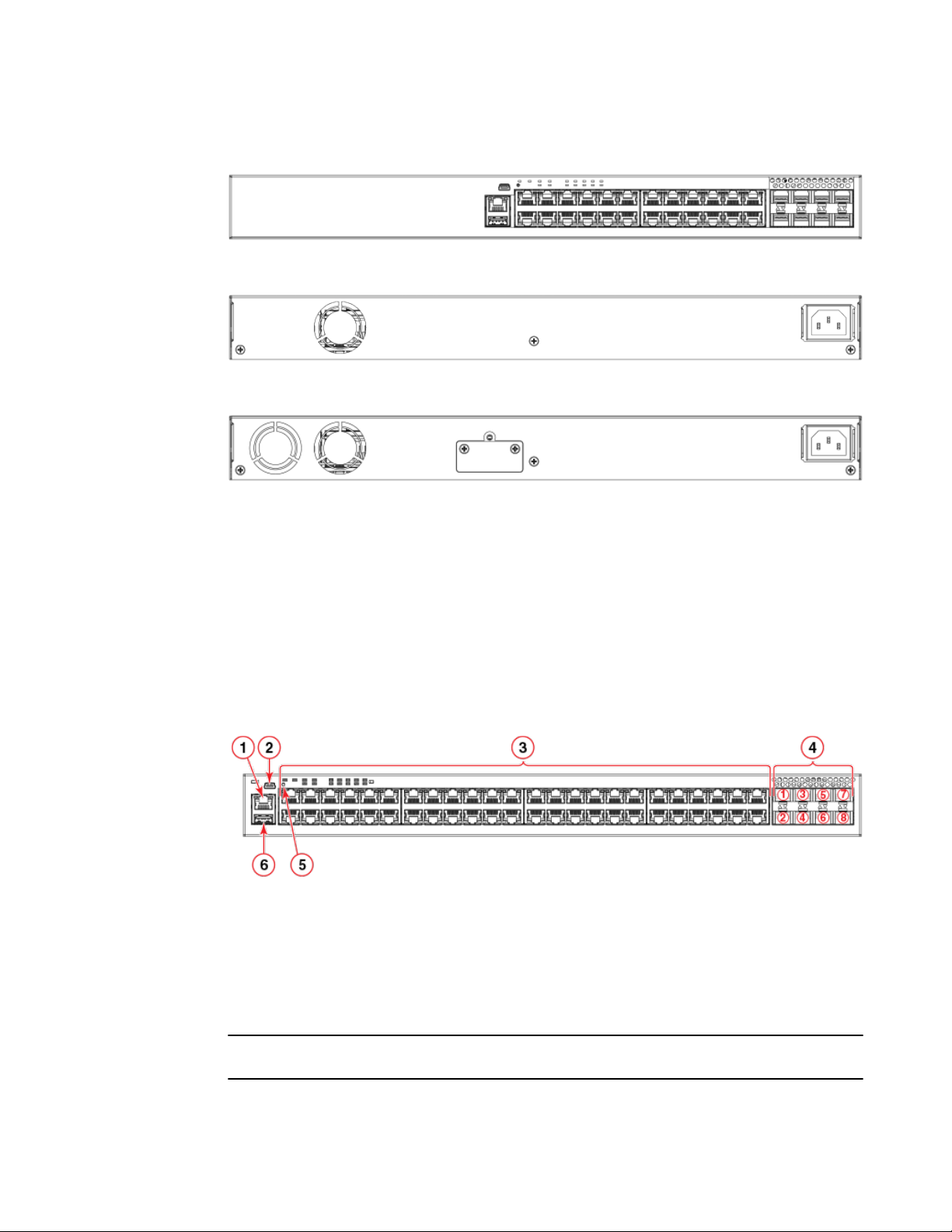
FIGURE 1 ICX 7250-48P front panel
EPS4000 connection
stacking ports, EPS4000 connection
stacking ports, EPS4000 connection
stacking ports, EPS4000 connection
stacking ports, EPS4000 connection
Brocade ICX 7250 Switch Hardware Installation Guide
53-1003622-02
13
Network and management interfaces
FIGURE 2 ICX 7250-24 front panel
FIGURE 3 ICX 7250-24G rear panel
FIGURE 4 ICX 7250-48 rear panel
Network and management interfaces
Each device includes the following management interfaces.
• Console management interface (mini-USB port)
• Out-of-band management interface (RJ-45 port)
• Reset
The ports are located on the front panels of the devices. The following is an example of a 48-port
device.
FIGURE 5 Network and management interfaces on a 48-port model
1. Out-of-band management port (RJ-45)
2. Console port (mini-USB)
3. Slot 1 (10/100/1000 Mbps ports - RJ-45)
4. Slot 2 (SFP+ uplink or stacking ports)
5. Reset
6. USB port
NOTE
24-port devices have similar front panels. For the ICX 7250-24G, the Slot 2 ports are SFP ports.
14 Brocade ICX 7250 Switch Hardware Installation Guide
53-1003622-02

Console management interface
Console management interface
The console management interface is a mini-USB port that allows you to configure and manage the
device using a third-party terminal emulation application from a directly connected PC or through a
terminal server.
Out-of-band management interface
The out-of-band management interface is an RJ-45 port that allows you to access, configure and
manage the device from the network.
System reset button
The reset button allows you to restart the system without switching the power supply off and on, using
the CLI. When the reset button is pressed, the system resets and the software is reloaded. The button
is accessible through a hole labeled RESET in the front panel.
Network interfaces for devices
The devices contain the following network interfaces.
• 10/100/1000 Mbps ports with RJ-45 copper connectors
• SFP or SFP+ ports
SFP ports support 1 Gbps port speed. SFP+ ports support both 1 Gbps and 10 Gbps port speeds.
NOTE
Refer to the Brocade ICX 7250 Switch Technical Specifications on page 73 to see the ports supported
by your model.
Slot designations
Refer to Network and management interfaces on page 14 for the location of slot 1 and slot 2 on the
front panel of the 24-port models and the 48-port models.
Slot designations for ICX 7250 devices TABLE 3
Device Slot 1 (10/100/1000 BASE-T ports) Slot 2 (SFP and SFP+ ports)
ICX 7250-24G RJ-45 ports 1-24 SFP ports 1-4
ICX 7250-24 RJ-45 ports 1-24 SFP+ ports 1-8
ICX 7250-24P RJ-45, PoE/PoE+ ports 1-24 SFP+ ports 1-8
ICX 7250-48 RJ-45 ports 1-48 SFP+ ports 1-8
ICX 7250-48P RJ-45, PoE/PoE+ ports 1-48 SFP+ ports 1-8
Brocade ICX 7250 Switch Hardware Installation Guide 15
53-1003622-02

10/100/1000 BASE-T ports
10/100/1000 BASE-T ports
All devices provide 24 or 48 RJ-45 ports that operate at 10 Mbps or 100 Mbps half or full duplex, or at
1000 Mbps full duplex. Because all ports support automatic MDI or MDI-X operation, you can use
straight-through cables for all network connections to PCs, servers, or other devices or hubs. In
addition, it is ideal (and preferred) to use straight-through cables for switch-to-switch connections.
Each port supports auto-negotiation, so the optimum transmission mode (half or full duplex), and the
data rate (10, 100, or 1000 Mbps) can be selected automatically. If a device connected to one of these
ports does not support auto-negotiation, the communication mode of the port can be configured
manually.
SFP or SFP+ fiber ports
The ICX 7250-24G contains four small form factor pluggable (SFP) ports (ports 1 through 4). The top
row consists of ports 1 and 3, and the bottom row consists of ports 2 and 4. These ports reside on slot
2 of the switch and can be used as uplink (data) ports. These ports support 1 Gbps but not 10 Gbps
port speeds.
All other ICX 7250 devices contain eight SFP+ ports that support 1 Gbps or 10 Gbps port speeds. The
top row ports are odd numbered (ports 1, 3, 5 and 7) and the bottom row ports are even numbered
(ports 2, 4, 6 and 8). All ports can be used for stacking or up-linking.
NOTE
You may need software licenses to enable some SFP+ ports at the full 10 Gbps. Check the FastIron
Ethernet Switch Software Licensing Guidefor more information.
For information about supported SFP and SFP+ transceivers, refer to the Brocade Optics Family
datasheet.
Specifying a port address
You can specify a port address for an uplink (data) port, a stacking port, or a management port.
Specifying a data port
The port address format is stack_unit/slot/port, where:
• stack_unit --Specifies the stack unit ID. The range is from 1 through the maximum number of
devices supported in a stack. Refer to the technical specifications for your device for the actual
value. If the device is not part of a stack, the stack unit ID is 1.
• slot --Specifies the slot number; either 1 or 2.
• port --Specifies the port number in the slot. The range is from 1 through 24 (24-port models) or 1
through 48 (48-port models) for the RJ-45 ports. For the SFP ports, the range is from 1 through 4,
and for the SFP+ ports, the range is from 1 through 8.
This example shows how to specify port 2 in slot 1 of a device that is not part of a stack:
Brocade (config) # interface ethernet 1/1/2
Specifying a stacking port
The port address format is stack_unit/slot/port where:
16 Brocade ICX 7250 Switch Hardware Installation Guide
53-1003622-02
Specifying a management port
• stack_unit --Specifies the stack unit ID. For models that support stacking, the range is from 1 through
the maximum number of devices (units) that can be supported in the stack.
• slot --Specifies the slot number. Stacking ports are in slot 2.
• port --Specifies the port number in the slot.
This example shows how to specify stacking port 3 in slot 2 of unit 3 in a stack:
Brocade (config) # interface ethernet 3/2/3
Specifying a management port
The management port number is always 1. This example shows how to specify the management port:
Brocade (config) # interface management 1
Port, system, and power status LEDs
The devices include LEDs that indicate the status of device components.
NOTE
Some examples of the port status LEDs are shown below. LEDs for similar ports are present for models
with higher number of ports.
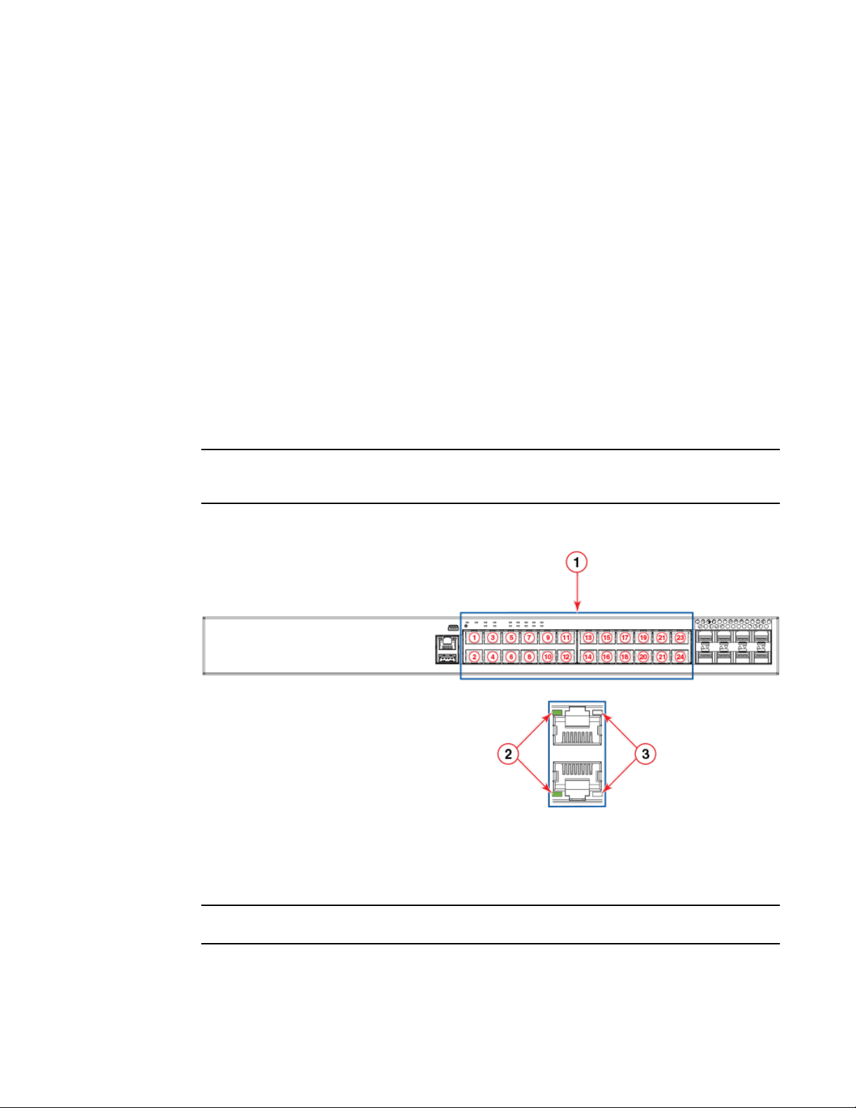
FIGURE 6 Port status LEDs on RJ-45 ports
1. RJ-45 ports
2. Status LEDs for corresponding ports
3. PoE/PoE+ LEDs for corresponding ports
NOTE
The PoE/PoE+ LEDs are reserved on models that do not support PoE or PoE+ operation.
Brocade ICX 7250 Switch Hardware Installation Guide 17
53-1003622-02
Overview
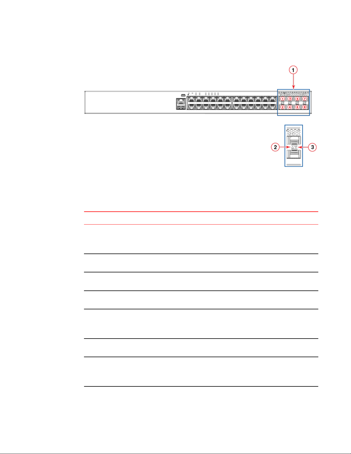
FIGURE 7 Port status LEDs for SFP or SFP+ ports
1. SFP or SFP+ ports
2. Bi-color status LED for upper port
3. Bi-color status LED for lower port
Port status LEDsTABLE 4
LED Condition Status
RJ-45 (1-24/48) On/Flashing Green The port has established a valid link
Off A link is not established with a
PoE/PoE+ (1-24/48) On/Green The port is providing PoE or PoE+
Off The port is not providing PoE or PoE
SFP (F1 - F4) for ICX 7250-24G
devices
SFP+ (X1 - X8) for all other ICX
7250 devices
On/Flashing Green The SFP port is operating at 1
Off A link is not established with a
On/Flashing Green The SFP+ port is operating at 10
at 10, 100 or 1000 Mbps. Flashing
indicates the port is transmitting and
receiving user packets.
remote port.
power to a connected device.
+ power.
Gbps. Flashing indicates the port is
transmitting and receiving user
packets at 1 Gbps.
remote port.
Gbps. Flashing indicates the port is
transmitting and receiving user
packets at 10 Gbps.
18 Brocade ICX 7250 Switch Hardware Installation Guide
53-1003622-02
Port status LEDs (Continued)TABLE 4
LED Condition Status
Overview
Out-of-band management port
(RJ-45)
On/Flashing Yellow The SFP+ port is operating at 1
Off A link is not established with a
On/Flashing Green
Gbps. Flashing indicates the port is
transmitting and receiving user
packets at 1 Gbps.
remote port.
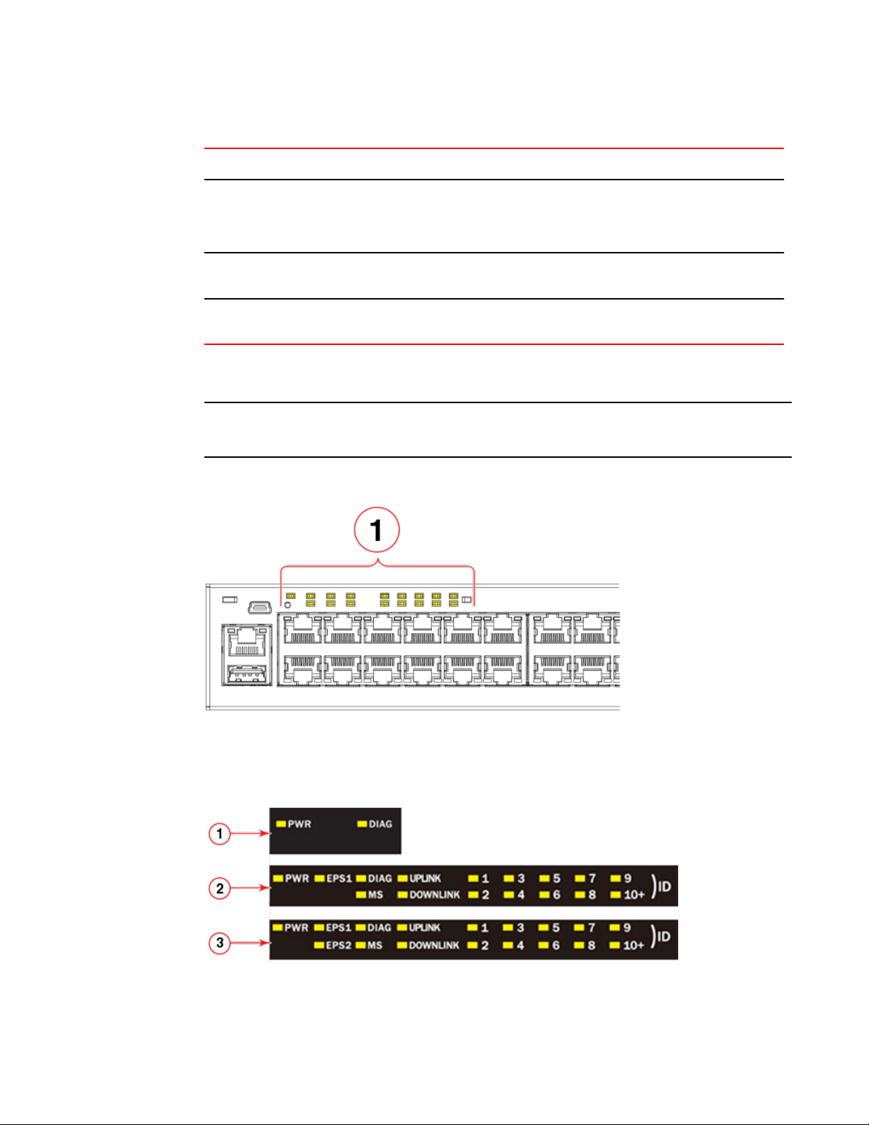
The following figure shows an example of the system status LEDs.
NOTE
Not all models have all the LEDs and the location of the LEDs on the front panel may also be slightly
different.
FIGURE 8 System status LEDs on ICX 7250-48P
1. System status LEDs
The following figure shows the system status LEDs for ICX 7250 models.
FIGURE 9 System status LEDs for ICX 7250 models
Brocade ICX 7250 Switch Hardware Installation Guide 19
53-1003622-02

Overview
1. ICX 7250-24G LEDs
2. ICX 7250-24, ICX 7250-24P, ICX 7250-48 LEDs
3. ICX 7250-48P LEDs
System status LEDsTABLE 5
LED Condition Status
PWR Green Power supply is operating normally.
Yellow Power supply fault.
Off Power supply off.
EPS1 and EPS2 (for supported
models)
DIAG Flashing Green System self-diagnostic test in
MS Green The device is the Active controller.
Green EPS1 and EPS2 power supplies are
operating normally.
Yellow EPS1 and EPS2 power supply fault.
Off EPS1 and EPS2 off or not present.
progress. System reloads
automatically.
Steady Yellow System self-diagnostic test has
detected a fault. (Fan, thermal, or
any interface fault.) The user must
reload the system.
Flashing indicates the system is
initializing.
Yellow Indicates the device is the Standby
controller. Flashing indicates the
system is in Master arbitration or
selection state.
Off Device is operating as a stack
member, or is in standalone mode.
UPLINK Green Uplink port is operating normally.
Off Uplink has failed or there is no link.
DOWNLINK Green Downlink port is operating normally.
Off Downlink has failed or there is no
20 Brocade ICX 7250 Switch Hardware Installation Guide
link.
53-1003622-02
System status LEDs (Continued)TABLE 5
LED Condition Status
Power supplies
1-10+ (ID)
(Switch ID in the stack)
Green Indicates the switch ID in the stack.
(Hardware can display 1-19 Stack
ID. The 10+ LED is used in
conjunction with another, 1-9, to
indicate numbers higher than 10.
The actual number of devices
supported in a stack is 12.)
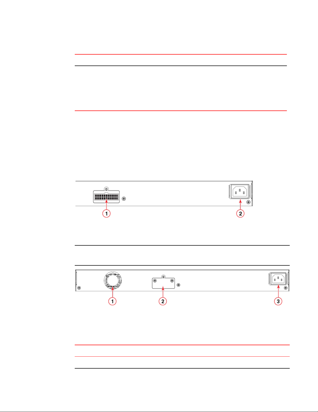
Power supplies
The devices have one standard, C14, AC power supply receptacle on the rear panel of the device for
the AC power cord. In addition, there is an optional connector on some models for the power cord from
an external power supply (EPS4000) that can provide DC power to the device in the event the internal
power supply fails or for supplemental power for PoE or PoE+ applications.
The following figure shows an example of a typical rear panel for an ICX 7250 device.
FIGURE 10 ICX 7250 power supply connectors
1. External power supply (EPS4000) connector
2. AC power supply socket
NOTE
The power connector for the EPS4000 is typically covered with a lid that is screwed on as shown in the
figure below. You should keep the connector covered when not in use.
1. Fan
2. External power supply (EPS4000) connector with cover on
3. AC power supply socket
TABLE 6
Model EPS4000 connectors
ICX 7250-24G 0
EPS4000 connectors on the ICX 7250 models
Brocade ICX 7250 Switch Hardware Installation Guide 21
53-1003622-02

Power supply usage
EPS4000 connectors on the ICX 7250 models (Continued)TABLE 6
Model EPS4000 connectors
ICX 7250-24 1
ICX 7250-24P 1
ICX 7250-48 1
ICX 7250-48P 1
Power supply usage
The device models support specific AC power supply inputs and numbers of PoE and PoE+ ports with
an internal power supply.
NOTE
Depending on the configuration, each EPS4000 connection from the device to the EPS4000 can add
23 ports of PoE (Class 3) or 12 ports of PoE+ power (54-volt supply) in addition to the internal power
supply by providing system power backup. If the overall PoE requirement is less than the power
budget of 360 W (or 720 W), the device can support 24 (or 48) PoE. The system power (12-volt
supply) portion of the EPS can be used for internal system power redundancy.
AC power supply and PoE and PoE+ usageTABLE 7
Model Maximum power draw
from AC line input (Watts)
ICX 7250-24G 44.4 0 0
ICX 7250-24 57.6 0 0
ICX 7250-24P 454.0 23 PoE ports (class 3) 12
ICX 7250-48 69.5 0 0
ICX 7250-48P 942.0 46 PoE ports (class 3) 24
Number of PoE ports supported
with internal power supply
Number of PoE+ ports
supported with internal
power supply
22 Brocade ICX 7250 Switch Hardware Installation Guide
53-1003622-02
Installation
● Items included with the ICX 7250 device........................................................................ 23
● Configuration requirements.............................................................................................24
● Summary of installation tasks......................................................................................... 24
● Installation precautions................................................................................................... 24
● Preparing the installation site.......................................................................................... 26
● Installing the device.........................................................................................................26
● Connecting devices in a traditional stack........................................................................ 31
● Powering on the system..................................................................................................33
DANGER
The procedures in this manual are for qualified service personnel.
DANGER
Before beginning the installation, see the precautions in “Power precautions.”
CAUTION
Disassembling any part of the power supply and fan assembly voids the warranty and regulatory
certifications. There are no user-serviceable parts inside the power supply and fan assembly.
Items included with the ICX 7250 device
ICX 7250 devices ship with all of the following items included in your shipping container. Verify the
contents of your shipping container. If any items are missing, contact the place of purchase.
• ICX 7250 device
• Rack mounting kit containing two L-shaped mounting brackets and two sets of eight sink-head
screws
• Wall mounting kit containing two wall-mount screws and two plastic anchors
• Two-post rack kit containing four rack-mounting screws and four cage nuts
• One AC power cord (US only)
• Power cord retainer clip
• Console cable
• DB9 adapter
• Four rubber feet
• China ROHS sheet
• Read Me First document
Brocade ICX 7250 Switch Hardware Installation Guide
53-1003622-02
23

Configuration requirements
Configuration requirements
To manage the ICX 7250, you need a management station, such as a PC running a terminal
emulation application, for serial connection to the device.
Use the serial connection to perform basic configuration tasks, including assigning an IP address and
network mask to the system. This information is required to manage the system using the CLI through
Telnet or Brocade Network Advisor.
Summary of installation tasks
Follow the steps in the following table to install your device. Details for each of these steps are
provided on the pages indicated.
Installation tasks TABLE 8
Task number Task Where to find more information
1 Ensure that the physical environment that will host the
device has the proper cabling and ventilation.
2 Unpack the device and all included accessories. Items included with the ICX 7250 device
3 Install the device on a desktop, or in an equipment
rack.
4 Once the device is installed, plug the device into a
nearby power source that adheres to the regulatory
requirements outlined in this manual.
Installation precautions
Follow all precautions when installing a device.
General precautions
DANGER
All fiber-optic interfaces use Class 1 lasers.
Preparing the installation site on page
26
on page 23
Installing the device on page 26
Powering on the system on page 33
CAUTION
Do not install the device in an environment where the operating ambient temperature might
exceed 50°C (122°F).
24 Brocade ICX 7250 Switch Hardware Installation Guide
53-1003622-02
Lifting precautions
CAUTION
Make sure the airflow around the front, sides, and back of the device is not restricted.
Lifting precautions
DANGER
Make sure the rack housing the device is adequately secured to prevent it from becoming
unstable or falling over.
DANGER
Mount the devices you install in a rack as low as possible. Place the heaviest device at the
bottom and progressively place lighter devices above.
Power precautions
CAUTION
Use a separate branch circuit for each AC power cord, which provides redundancy in case one
of the circuits fails.
CAUTION
Ensure that the device does not overload the power circuits, wiring, and over-current protection.
To determine the possibility of overloading the supply circuits, add the ampere (amp) ratings of
all devices installed on the same circuit as the device. Compare this total with the rating limit for
the circuit. The maximum ampere ratings are usually printed on the devices near the input
power connectors.
DANGER
Disconnect the power cord from all power sources to completely remove power from the device.
DANGER
If the installation requires a different power cord than the one supplied with the device, make
sure you use a power cord displaying the mark of the safety agency that defines the regulations
for power cords in your country. The mark is your assurance that the power cord can be used
safely with the device.
Brocade ICX 7250 Switch Hardware Installation Guide 25
53-1003622-02

Preparing the installation site
Preparing the installation site
Before installing the device, plan its location and orientation relative to other devices and equipment.
Cabling infrastructure
Ensure that the proper cabling is installed at the site. For information about supported SFP and SFP+
transceivers and cable lengths and types, refer to the Brocade optics family datasheet.
Installation location
Devices can be mounted in a standard 19-inch equipment rack, on the wall, or on a flat surface.
The site should meet the following requirements:
• Maintain the operating environment as specified in the Technical Specifications.
• Allow a minimum of 7.62 cm (3 in.) of space between the front and the back of the device and walls
or other obstructions for proper airflow.
• Allow at least 7.62 cm (3 in.) of space at the front and back of the device for the twisted-pair, fiberoptic, and power cabling.
• The site should be accessible for installing, cabling, and maintaining the devices.
• Allow the status LEDs to be clearly visible.
• Allow for twisted-pair cables to be routed away from power lines, fluorescent lighting fixtures, and
other sources of electrical interference, such as radios and transmitters.
• Allow for the unit to be connected to a separate grounded power outlet that provides 100 to 240
VAC, 50 to 60 Hz, is within 2 m (6.6 ft) of each device, and is powered from an independent circuit
breaker. As with any equipment, a filter or surge suppressor is recommended.
• Some combinations of intake and exhaust airflows may not be compatible with your environment.
Rack-mount installation considerations
Before mounting the device in a rack, ensure that the following rack-mount installation requirements
are met:
• Temperature: Because the temperature within a rack assembly may be higher than the ambient
room temperature, check that the rack-environment temperature is within the specified operating
temperature range. (Refer to Brocade ICX 7250 Switch Technical Specifications on page 73.)
• Airflow: Be sure that the airflow direction for all equipment in a rack is the same or consistent.
• Mechanical loading: Do not place any equipment on top of a rack-mounted unit.
• Circuit overloading: Be sure that the supply circuit to the rack assembly is not overloaded.
• Grounding: Rack-mounted equipment should be properly grounded.
Installing the device
You can install the device on a desktop, the wall, or in an equipment rack.
26 Brocade ICX 7250 Switch Hardware Installation Guide
53-1003622-02
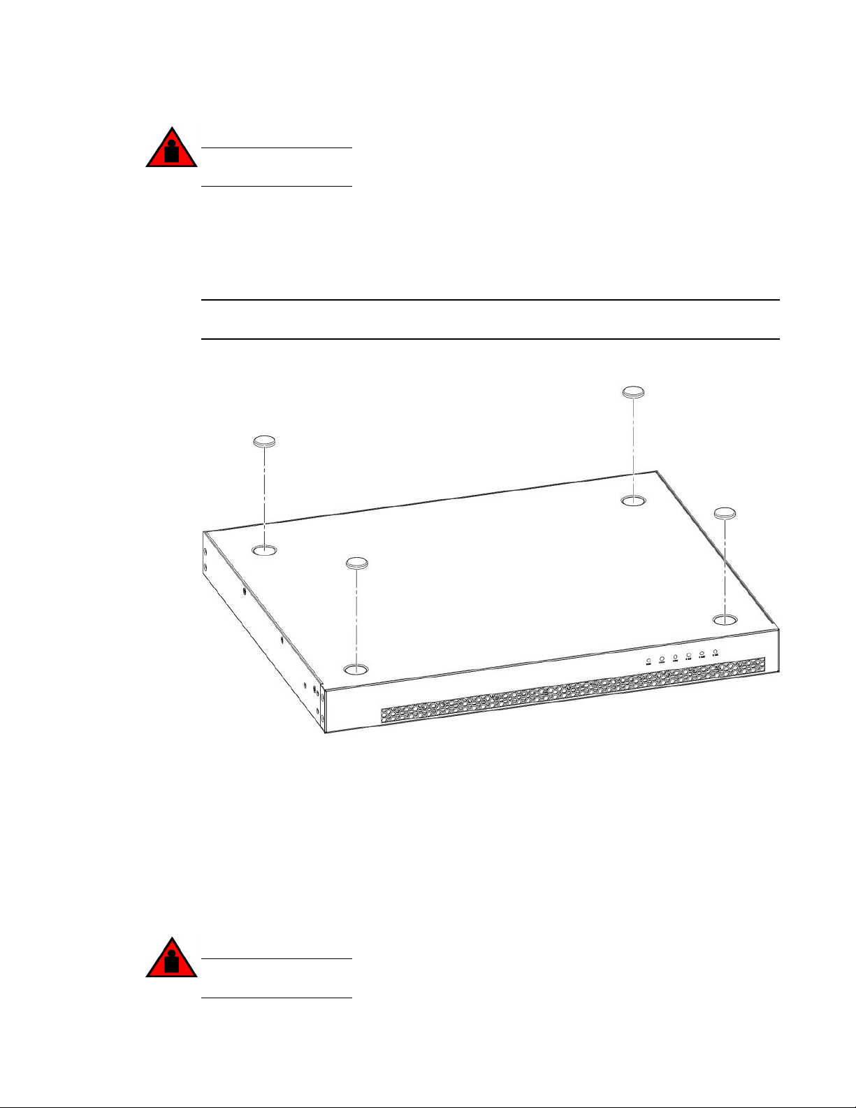
Desktop installation
DANGER
Mount the devices you install in a rack as low as possible. Place the heaviest device at the
bottom and progressively place lighter devices above.
Desktop installation
Complete the following steps to install the ICX 7250 device on a desktop or other flat surface.
NOTE
The device shown in the diagram may be different from the one you have.
FIGURE 11 Attaching the adhesive feet
1. Attach the four adhesive feet to the bottom of the device. If installing multiple devices, attach the
adhesive feet to each device.
2. Set the device on a flat desktop, table, or shelf near an AC power source. Make sure that adequate
ventilation is provided for the system. A 7.62 cm (3 in) clearance is recommended on each side.
3. If installing a single device only, go to the “Powering on the system” task. If installing multiple devices
place each device squarely on top of the one below.
Rack mount installation (2-post)
The devices use stationary mounting when mounted in a rack.
DANGER
Make sure the rack housing the device is adequately secured to prevent it from becoming
unstable or falling over.
Brocade ICX 7250 Switch Hardware Installation Guide 27
53-1003622-02
Installation
NOTE
You need a #2 Phillips screwdriver for rack mount installation.
Complete the following steps to mount devices in a rack. The example shows a front-mounting.
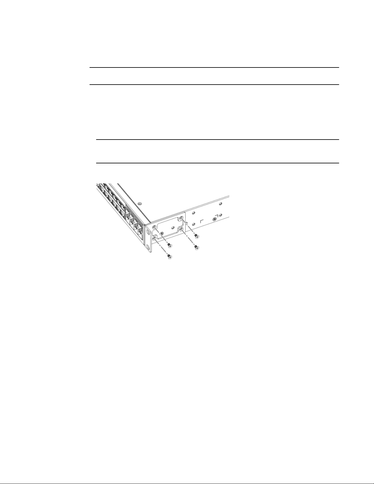
1. Remove the rack mounting kit from the shipping carton. The kit contains two L-shaped mounting
brackets and two sets of eight sink-head screws.
2. Using a Phillips screwdriver, attach the mounting brackets to the sides of the device using eight
#6-32, sink-head screws, four screws on each side.
NOTE
The #6-32, sink-head screws are for front- and mid-mounting. Use the #8-32 screws for rearmounting.
FIGURE 12 Attaching the rack mounting brackets for ICX 7250
3. Remove the two-post rack kit from the shipping carton. The kit contains four rack-mounting screws
and four cage nuts.
4. Insert the cage nuts in the two-post rack where you want to mount the device.
5. Using a Phillips screwdriver, mount the device in a two-post rack using four rack-mounting screws.
28 Brocade ICX 7250 Switch Hardware Installation Guide
53-1003622-02
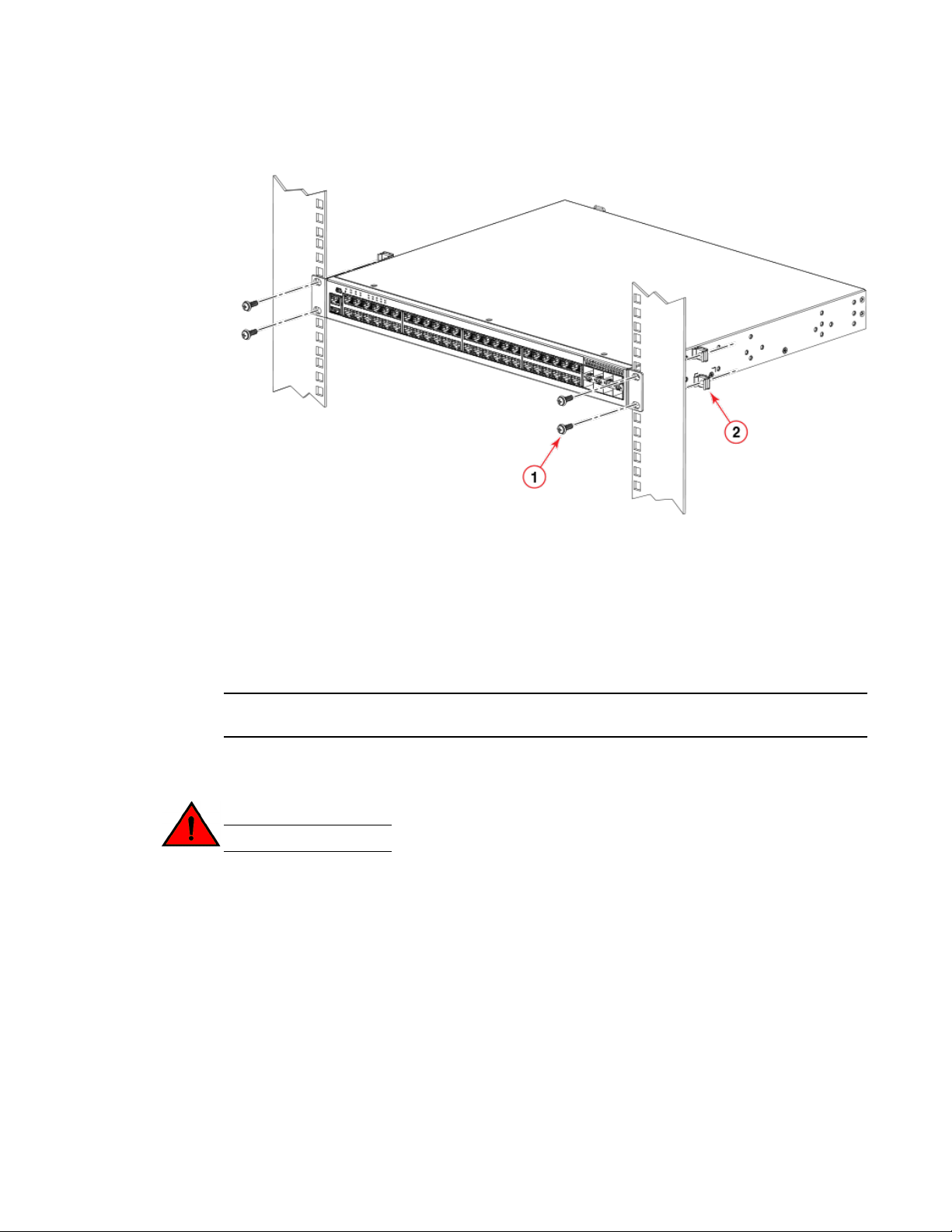
FIGURE 13 Installing the device in a two-post rack
Wall mount installation
1. Rack-mounting screws
2. Cage nuts
6. If installing a single device only, proceed to Powering on the system on page 33. If installing
multiple devices, mount them in the rack, one above the other.
Wall mount installation
NOTE
You need a #2 Phillips screwdriver, a hammer, and a drill for wall mount installation.
Brocade recommends that you wall mount the device with the port side down.
Complete the following steps to mount the device to a wall.
DANGER
This equipment is suitable for mounting on concrete or other noncombustible surfaces only.
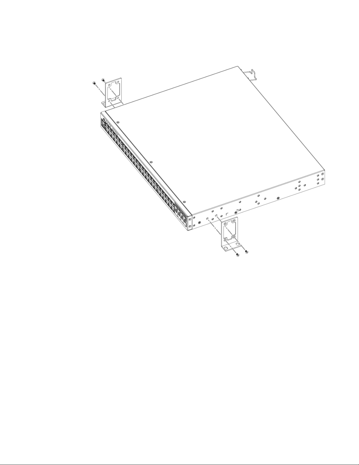
1. Attach the four adhesive feet to the bottom of the device.
2. Using a Phillips screwdriver, attach the wall mount brackets to the sides of the device using four
#6-32, sink-head screws on each side.
Brocade ICX 7250 Switch Hardware Installation Guide 29
53-1003622-02
Installation
FIGURE 14 Attaching the wall mount brackets
3. Drill two holes on the wall where you want to mount the device.
4. Hammer two wall mount anchors into the holes on the wall.
5. Use the two wall mount screws to fasten the device to the wall mount anchors.
30 Brocade ICX 7250 Switch Hardware Installation Guide
53-1003622-02
 Loading...