

Page 1

53-1002603-01
®
28 September 2012
Brocade ICX 6650
Layer 3 Routing Configuration Guide
Supporting FastIron Software Release 07.5.00
Page 2

Copyright © 2012 Brocade Communications Systems, Inc. All Rights Reserved.
Brocade, Brocade Assurance, the B-wing symbol, BigIron, DCX, Fabric OS, FastIron, MLX, NetIron, SAN Health, ServerIron,
TurboIron, VCS, and VDX are registered trademarks, and AnyIO, Brocade One, CloudPlex, Effortless Networking, ICX, NET Health,
OpenScript, and The Effortless Network are trademarks of Brocade Communications Systems, Inc., in the United States and/or in
other countries. Other brands, products, or service names mentioned may be trademarks of their respective owners.
Notice: This document is for informational purposes only and does not set forth any warranty, expressed or implied, concerning
any equipment, equipment feature, or service offered or to be offered by Brocade. Brocade reserves the right to make changes to
this document at any time, without notice, and assumes no responsibility for its use. This informational document describes
features that may not be currently available. Contact a Brocade sales office for information on feature and product availability.
Export of technical data contained in this document may require an export license from the United States government.
The authors and Brocade Communications Systems, Inc. shall have no liability or responsibility to any person or entity with
respect to any loss, cost, liability, or damages arising from the information contained in this book or the computer programs that
accompany it.
The product described by this document may contain “open source” software covered by the GNU General Public License or other
open source license agreements. To find out which open source software is included in Brocade products, view the licensing
terms applicable to the open source software, and obtain a copy of the programming source code, please visit
http://www.brocade.com/support/oscd.
Brocade Communications Systems, Incorporated
Corporate and Latin American Headquarters
Brocade Communications Systems, Inc.
130 Holger Way
San Jose, CA 95134
Tel: 1-408-333-8000
Fax: 1-408-333-8101
E-mail: info@brocade.com
European Headquarters
Brocade Communications Switzerland Sàrl
Centre Swissair
Tour B - 4ème étage
29, Route de l'Aéroport
Case Postale 105
CH-1215 Genève 15
Switzerland
Tel: +41 22 799 5640
Fax: +41 22 799 5641
E-mail: emea-info@brocade.com
Asia-Pacific Headquarters
Brocade Communications Systems China HK, Ltd.
No. 1 Guanghua Road
Chao Yang District
Units 2718 and 2818
Beijing 100020, China
Tel: +8610 6588 8888
Fax: +8610 6588 9999
E-mail: china-info@brocade.com
Asia-Pacific Headquarters
Brocade Communications Systems Co., Ltd. (Shenzhen WFOE)
Citic Plaza
No. 233 Tian He Road North
Unit 1308 – 13th Floor
Guangzhou, China
Tel: +8620 3891 2000
Fax: +8620 3891 2111
E-mail: china-info@brocade.com
Document History
Title Publication number Summary of changes Date
Brocade ICX 6650 Layer 3 Routing
Configuration Guide
53-1002603-01 Release 07.4.00 document
updated with
enhancements in Release
07.5.00
September 2012
Page 3

Contents
About This Document
Audience . . . . . . . . . . . . . . . . . . . . . . . . . . . . . . . . . . . . . . . . . . . . . . . . xi
Supported hardware and software . . . . . . . . . . . . . . . . . . . . . . . . . . . xi
Brocade ICX 6650 slot and port numbering . . . . . . . . . . . . . . . . . . . .xi
How this document is organized . . . . . . . . . . . . . . . . . . . . . . . . . . . . xii
Document conventions. . . . . . . . . . . . . . . . . . . . . . . . . . . . . . . . . . . . xiii
Text formatting . . . . . . . . . . . . . . . . . . . . . . . . . . . . . . . . . . . . . . . xiii
Command syntax conventions . . . . . . . . . . . . . . . . . . . . . . . . . . xiii
Notes, cautions, and warnings . . . . . . . . . . . . . . . . . . . . . . . . . . xiii
Notice to the reader . . . . . . . . . . . . . . . . . . . . . . . . . . . . . . . . . . . . . . xiv
Related publications . . . . . . . . . . . . . . . . . . . . . . . . . . . . . . . . . . . . . . xiv
Additional information. . . . . . . . . . . . . . . . . . . . . . . . . . . . . . . . . . . . . xv
Brocade resources. . . . . . . . . . . . . . . . . . . . . . . . . . . . . . . . . . . . xv
Other industry resources. . . . . . . . . . . . . . . . . . . . . . . . . . . . . . . xv
Getting technical help. . . . . . . . . . . . . . . . . . . . . . . . . . . . . . . . . . . . . xv
Document feedback . . . . . . . . . . . . . . . . . . . . . . . . . . . . . . . . . . . . . . xvi
Chapter 1 IP Configuration
Basic IP configuration. . . . . . . . . . . . . . . . . . . . . . . . . . . . . . . . . . . . . . 2
IP configuration overview . . . . . . . . . . . . . . . . . . . . . . . . . . . . . . . . . . . 2
Full Layer 3 support . . . . . . . . . . . . . . . . . . . . . . . . . . . . . . . . . . . . 2
IP interfaces . . . . . . . . . . . . . . . . . . . . . . . . . . . . . . . . . . . . . . . . . . 3
IP packet flow through a Layer 3 Switch. . . . . . . . . . . . . . . . . . . . 5
IP route exchange protocols . . . . . . . . . . . . . . . . . . . . . . . . . . . . . 9
IP multicast protocols . . . . . . . . . . . . . . . . . . . . . . . . . . . . . . . . . 10
IP interface redundancy protocols . . . . . . . . . . . . . . . . . . . . . . .10
ACLs and IP access policies . . . . . . . . . . . . . . . . . . . . . . . . . . . .10
Basic IP parameters and defaults – Layer 3 Switches. . . . . . . . . . . 11
When parameter changes take effect . . . . . . . . . . . . . . . . . . . .11
IP global parameters – Layer 3 Switches . . . . . . . . . . . . . . . . . . 11
IP interface parameters – Layer 3 Switches . . . . . . . . . . . . . . .15
Basic IP parameters and defaults – Layer 2 Switches. . . . . . . . . . . 17
IP global parameters – Layer 2 Switches . . . . . . . . . . . . . . . . . . 17
Interface IP parameters – Layer 2 Switches . . . . . . . . . . . . . . .19
Brocade ICX 6650 Layer 3 Routing Configuration Guide iii
53-1002603-01
Page 4

Configuring IP parameters – Layer 3 Switches . . . . . . . . . . . . . . . . .19
Configuring IP addresses. . . . . . . . . . . . . . . . . . . . . . . . . . . . . . .19
Configuring 31-bit subnet masks on
point-to-point networks . . . . . . . . . . . . . . . . . . . . . . . . . . . . . . . . 23
Configuring DNS resolver . . . . . . . . . . . . . . . . . . . . . . . . . . . . . . 25
Configuring packet parameters . . . . . . . . . . . . . . . . . . . . . . . . . 28
Changing the router ID. . . . . . . . . . . . . . . . . . . . . . . . . . . . . . . . .31
Specifying a single source interface for specified
packet types . . . . . . . . . . . . . . . . . . . . . . . . . . . . . . . . . . . . . . . . . 31
ARP parameter configuration . . . . . . . . . . . . . . . . . . . . . . . . . . .35
Configuring forwarding parameters . . . . . . . . . . . . . . . . . . . . . .40
Disabling ICMP messages . . . . . . . . . . . . . . . . . . . . . . . . . . . . . . 43
Disabling ICMP redirect messages . . . . . . . . . . . . . . . . . . . . . . . 44
Static routes configuration . . . . . . . . . . . . . . . . . . . . . . . . . . . . .45
Configuring a default network route . . . . . . . . . . . . . . . . . . . . . .54
Configuring IP load sharing . . . . . . . . . . . . . . . . . . . . . . . . . . . . . 55
ICMP Router Discovery Protocol configuration . . . . . . . . . . . . .58
IRDP parameters . . . . . . . . . . . . . . . . . . . . . . . . . . . . . . . . . . . . .59
Reverse Address Resolution Protocol configuration . . . . . . . . .61
Configuring UDP broadcast and IP helper parameters . . . . . . . 62
BootP and DHCP relay parameter configuration . . . . . . . . . . . .65
DHCP Server. . . . . . . . . . . . . . . . . . . . . . . . . . . . . . . . . . . . . . . . .67
Displaying DHCP Server information . . . . . . . . . . . . . . . . . . . . .78
DHCP Client-Based Auto-Configuration and flash
image update . . . . . . . . . . . . . . . . . . . . . . . . . . . . . . . . . . . . . . . .80
Configuring IP parameters – Layer 2 Switches . . . . . . . . . . . . . . . . .88
Configuring the management IP address and specifying
the default gateway . . . . . . . . . . . . . . . . . . . . . . . . . . . . . . . . . . .88
Configuring Domain Name Server resolver . . . . . . . . . . . . . . . .89
Changing the TTL threshold . . . . . . . . . . . . . . . . . . . . . . . . . . . .90
DHCP Assist configuration. . . . . . . . . . . . . . . . . . . . . . . . . . . . . . 91
IPv4 point-to-point GRE tunnels . . . . . . . . . . . . . . . . . . . . . . . . . . . . .95
IPv4 GRE tunnel overview . . . . . . . . . . . . . . . . . . . . . . . . . . . . . .95
GRE packet structure and header format . . . . . . . . . . . . . . . . .95
Path MTU Discovery (PMTUD) support . . . . . . . . . . . . . . . . . . . . 96
Configuration considerations for PMTUD support . . . . . . . . . . . 97
Support for IPv4 multicast routing over GRE tunnels . . . . . . . . 97
GRE support with other features . . . . . . . . . . . . . . . . . . . . . . . .98
Configuration considerations for GRE IP tunnels . . . . . . . . . . .98
Configuration tasks for GRE tunnels . . . . . . . . . . . . . . . . . . . .100
Point-to-point GRE tunnel configuration example . . . . . . . . . .107
Displaying GRE tunneling information . . . . . . . . . . . . . . . . . . .108
Clearing GRE statistics . . . . . . . . . . . . . . . . . . . . . . . . . . . . . . .112
Displaying IP configuration information and statistics . . . . . . . . . .113
Changing the network mask display to prefix format . . . . . . .113
Displaying IP information – Layer 3 Switches . . . . . . . . . . . . .113
Displaying IP information – Layer 2 Switches . . . . . . . . . . . . .128
iv Brocade ICX 6650 Layer 3 Routing Configuration Guide
53-1002603-01
Page 5

Chapter 2 Base Layer 3 and Routing Protocols
Adding a static IP route . . . . . . . . . . . . . . . . . . . . . . . . . . . . . . . . . . .133
Adding a static ARP entry . . . . . . . . . . . . . . . . . . . . . . . . . . . . . . . . .134
Modifying and displaying Layer 3 system parameter limits . . . . . .134
Layer 3 configuration notes. . . . . . . . . . . . . . . . . . . . . . . . . . . .134
Displaying Layer 3 system parameter limits . . . . . . . . . . . . . .135
Configuring RIP . . . . . . . . . . . . . . . . . . . . . . . . . . . . . . . . . . . . . . . . .136
Enabling RIP . . . . . . . . . . . . . . . . . . . . . . . . . . . . . . . . . . . . . . . .136
Enabling redistribution of IP static routes into RIP . . . . . . . . .136
Configuring a redistribution filter . . . . . . . . . . . . . . . . . . . . . . .137
Enabling redistribution . . . . . . . . . . . . . . . . . . . . . . . . . . . . . . .138
Enabling learning of default routes . . . . . . . . . . . . . . . . . . . . .138
Changing the route loop prevention method . . . . . . . . . . . . . .138
Other Layer 3 protocols. . . . . . . . . . . . . . . . . . . . . . . . . . . . . . . . . . .139
Enabling or disabling routing protocols . . . . . . . . . . . . . . . . . . . . . .139
Enabling or disabling Layer 2 switching . . . . . . . . . . . . . . . . . . . . .139
Configuration notes and feature limitations for
Layer 2 switching . . . . . . . . . . . . . . . . . . . . . . . . . . . . . . . . . . . .140
Command syntax for Layer 2 switching . . . . . . . . . . . . . . . . . .140
Chapter 3 RIP (IPv4)
RIP overview . . . . . . . . . . . . . . . . . . . . . . . . . . . . . . . . . . . . . . . . . . .141
RIP parameters and defaults . . . . . . . . . . . . . . . . . . . . . . . . . . . . . .142
RIP global parameters . . . . . . . . . . . . . . . . . . . . . . . . . . . . . . . .142
RIP interface parameters . . . . . . . . . . . . . . . . . . . . . . . . . . . . .143
RIP parameter configuration . . . . . . . . . . . . . . . . . . . . . . . . . . . . . .144
Enabling RIP . . . . . . . . . . . . . . . . . . . . . . . . . . . . . . . . . . . . . . . .144
Enabling ECMP for routes in RIP . . . . . . . . . . . . . . . . . . . . . . . .144
Configuring metric parameters . . . . . . . . . . . . . . . . . . . . . . . . .144
Changing the administrative distance. . . . . . . . . . . . . . . . . . .146
Configuring redistribution . . . . . . . . . . . . . . . . . . . . . . . . . . . . .146
Route learning and advertising parameters . . . . . . . . . . . . . .148
Denying route advertisements for connected routes . . . . . . .150
Changing the route loop prevention method . . . . . . . . . . . . . .150
Suppressing RIP route advertisement on a VRRP or
VRRP-E backup interface. . . . . . . . . . . . . . . . . . . . . . . . . . . . . .151
Configuring RIP route filters . . . . . . . . . . . . . . . . . . . . . . . . . . .151
Displaying RIP filters . . . . . . . . . . . . . . . . . . . . . . . . . . . . . . . . . . . . .153
Displaying CPU utilization statistics . . . . . . . . . . . . . . . . . . . . . . . . .154
Chapter 4 RIP (IPv6)
RIPng overview . . . . . . . . . . . . . . . . . . . . . . . . . . . . . . . . . . . . . . . . .157
Summary of configuration tasks . . . . . . . . . . . . . . . . . . . . . . . . . . .158
RIPng configuration. . . . . . . . . . . . . . . . . . . . . . . . . . . . . . . . . . . . . .158
Enabling RIPng . . . . . . . . . . . . . . . . . . . . . . . . . . . . . . . . . . . . . .158
Brocade ICX 6650 Layer 3 Routing Configuration Guide v
53-1002603-01
Page 6

RIPng timers . . . . . . . . . . . . . . . . . . . . . . . . . . . . . . . . . . . . . . . . . . .159
Updating RIPng timers. . . . . . . . . . . . . . . . . . . . . . . . . . . . . . . .159
Route learning and advertising parameters . . . . . . . . . . . . . . . . . .160
Configuring default route learning and advertising . . . . . . . . .160
Advertising IPv6 address summaries . . . . . . . . . . . . . . . . . . . .160
Changing the metric of routes learned and
advertised on an interface . . . . . . . . . . . . . . . . . . . . . . . . . . . . 161
Redistributing routes into RIPng . . . . . . . . . . . . . . . . . . . . . . . . . . . 161
Controlling distribution of routes through RIPng. . . . . . . . . . . . . . .162
Configuring poison reverse parameters . . . . . . . . . . . . . . . . . . . . .162
Clearing RIPng routes from the IPv6 route table. . . . . . . . . . . . . . .163
Displaying the RIPng configuration . . . . . . . . . . . . . . . . . . . . . . . . .164
Displaying RIPng routing table . . . . . . . . . . . . . . . . . . . . . . . . . . . . .165
Chapter 5 OSPF version 2 (IPv4)
OSPF overview. . . . . . . . . . . . . . . . . . . . . . . . . . . . . . . . . . . . . . . . . .168
OSPF point-to-point links . . . . . . . . . . . . . . . . . . . . . . . . . . . . . .169
Designated routers in multi-access networks . . . . . . . . . . . . .170
Designated router election in multi-access networks . . . . . . .170
OSPF RFC 1583 and 2178 compliance . . . . . . . . . . . . . . . . . . 171
Reduction of equivalent AS External LSAs . . . . . . . . . . . . . . . .172
Support for OSPF RFC 2328 Appendix E . . . . . . . . . . . . . . . . . 174
Dynamic OSPF activation and configuration . . . . . . . . . . . . . .175
Dynamic OSPF memory . . . . . . . . . . . . . . . . . . . . . . . . . . . . . . . 176
OSPF graceful restart . . . . . . . . . . . . . . . . . . . . . . . . . . . . . . . . . . . . 176
Configuring OSPF . . . . . . . . . . . . . . . . . . . . . . . . . . . . . . . . . . . . . . . 177
OSPF configuration rules. . . . . . . . . . . . . . . . . . . . . . . . . . . . . .177
OSPF parameters. . . . . . . . . . . . . . . . . . . . . . . . . . . . . . . . . . . .177
Enabling OSPF on the router. . . . . . . . . . . . . . . . . . . . . . . . . . .178
Assigning OSPF areas . . . . . . . . . . . . . . . . . . . . . . . . . . . . . . . .179
Assigning an area range (optional). . . . . . . . . . . . . . . . . . . . . .183
Assigning interfaces to an area . . . . . . . . . . . . . . . . . . . . . . . .184
Modifying interface defaults . . . . . . . . . . . . . . . . . . . . . . . . . . .184
Changing the timer for OSPF authentication changes . . . . . .186
Block flooding of outbound LSAs on specific
OSPF interfaces . . . . . . . . . . . . . . . . . . . . . . . . . . . . . . . . . . . . .187
Configuring an OSPF non-broadcast interface. . . . . . . . . . . . .188
Assigning virtual links . . . . . . . . . . . . . . . . . . . . . . . . . . . . . . . .189
Modifying virtual link parameters . . . . . . . . . . . . . . . . . . . . . . .191
Changing the reference bandwidth for the cost
on OSPF interfaces . . . . . . . . . . . . . . . . . . . . . . . . . . . . . . . . . .192
Defining redistribution filters . . . . . . . . . . . . . . . . . . . . . . . . . .194
Preventing specific OSPF routes from being installed
in the IP route table . . . . . . . . . . . . . . . . . . . . . . . . . . . . . . . . . .197
Modifying the default metric for redistribution . . . . . . . . . . . .200
Enabling route redistribution. . . . . . . . . . . . . . . . . . . . . . . . . . .200
Disabling or re-enabling load sharing. . . . . . . . . . . . . . . . . . . .202
Configuring external route summarization . . . . . . . . . . . . . . . .204
vi Brocade ICX 6650 Layer 3 Routing Configuration Guide
53-1002603-01
Page 7

Configuring default route origination . . . . . . . . . . . . . . . . . . . .205
Modifying SPF timers. . . . . . . . . . . . . . . . . . . . . . . . . . . . . . . . .206
Modifying the redistribution metric type . . . . . . . . . . . . . . . . .207
Administrative distance. . . . . . . . . . . . . . . . . . . . . . . . . . . . . . .207
Configuring OSPF group Link State Advertisement pacing . . .208
Modifying OSPF traps generated . . . . . . . . . . . . . . . . . . . . . . .208
Specifying the types of OSPF Syslog messages to log . . . . . .209
Modifying the OSPF standard compliance setting. . . . . . . . . .210
Modifying the exit overflow interval . . . . . . . . . . . . . . . . . . . . . 210
Configuring an OSPF point-to-point link . . . . . . . . . . . . . . . . . .211
Configuring OSPF graceful restart . . . . . . . . . . . . . . . . . . . . . .211
Clearing OSPF information . . . . . . . . . . . . . . . . . . . . . . . . . . . . . . . .212
Clearing OSPF neighbor information . . . . . . . . . . . . . . . . . . . .212
Clearing OSPF topology information . . . . . . . . . . . . . . . . . . . . .213
Clearing redistributed routes from the OSPF routing table . . .213
Clearing information for OSPF areas . . . . . . . . . . . . . . . . . . . .213
Displaying OSPF information . . . . . . . . . . . . . . . . . . . . . . . . . . . . . .214
Displaying general OSPF configuration information . . . . . . . .214
Displaying CPU utilization statistics . . . . . . . . . . . . . . . . . . . . . 215
Displaying OSPF area information . . . . . . . . . . . . . . . . . . . . . .216
Displaying OSPF neighbor information. . . . . . . . . . . . . . . . . . .217
Displaying OSPF interface information. . . . . . . . . . . . . . . . . . .219
Displaying OSPF route information . . . . . . . . . . . . . . . . . . . . . .220
Displaying OSPF external link state information . . . . . . . . . . .222
Displaying OSPF link state information . . . . . . . . . . . . . . . . . .223
Displaying the data in an LSA . . . . . . . . . . . . . . . . . . . . . . . . . .224
Displaying OSPF virtual neighbor information . . . . . . . . . . . . .224
Displaying OSPF virtual link information . . . . . . . . . . . . . . . . .224
Displaying OSPF ABR and ASBR information. . . . . . . . . . . . . .225
Displaying OSPF trap status . . . . . . . . . . . . . . . . . . . . . . . . . . .225
Displaying OSPF graceful restart information . . . . . . . . . . . . .226
Chapter 6 OSPF version 3 (IPv6)
OSPF (IPv6) overview . . . . . . . . . . . . . . . . . . . . . . . . . . . . . . . . . . . .227
Differences between OSPF V2 and OSPF V3 . . . . . . . . . . . . . . . . .228
Link state advertisement types for OSPF V3. . . . . . . . . . . . . . . . . .228
OSPF V3 configuration . . . . . . . . . . . . . . . . . . . . . . . . . . . . . . . . . . .229
Enabling OSPF V3 . . . . . . . . . . . . . . . . . . . . . . . . . . . . . . . . . . .229
Assigning OSPF V3 areas . . . . . . . . . . . . . . . . . . . . . . . . . . . . .230
Assigning interfaces to an area . . . . . . . . . . . . . . . . . . . . . . . .231
Configuring virtual links. . . . . . . . . . . . . . . . . . . . . . . . . . . . . . .231
Changing the reference bandwidth for the cost on
OSPF V3 interfaces . . . . . . . . . . . . . . . . . . . . . . . . . . . . . . . . . .234
Redistributing routes into OSPF V3 . . . . . . . . . . . . . . . . . . . . .235
External route summarization. . . . . . . . . . . . . . . . . . . . . . . . . .238
Filtering OSPF V3 routes . . . . . . . . . . . . . . . . . . . . . . . . . . . . . .239
Default route origination . . . . . . . . . . . . . . . . . . . . . . . . . . . . . .242
Shortest path first timers . . . . . . . . . . . . . . . . . . . . . . . . . . . . .243
Administrative distance. . . . . . . . . . . . . . . . . . . . . . . . . . . . . . .244
Brocade ICX 6650 Layer 3 Routing Configuration Guide vii
53-1002603-01
Page 8

Configuring the OSPF V3 LSA pacing interval . . . . . . . . . . . . .245
Modifying exit overflow interval. . . . . . . . . . . . . . . . . . . . . . . . .245
Modifying external link state database limit . . . . . . . . . . . . . .245
Modifying OSPF V3 interface defaults . . . . . . . . . . . . . . . . . . .246
Disabling or re-enabling event logging . . . . . . . . . . . . . . . . . . .247
IPsec for OSPF V3 . . . . . . . . . . . . . . . . . . . . . . . . . . . . . . . . . . . 247
IPsec for OSPF V3 configuration. . . . . . . . . . . . . . . . . . . . . . . .248
Displaying OSPF V3 Information . . . . . . . . . . . . . . . . . . . . . . . . . . .254
Displaying OSPF V3 area information. . . . . . . . . . . . . . . . . . . .255
Displaying OSPF V3 database information. . . . . . . . . . . . . . . .256
Displaying OSPF V3 interface information . . . . . . . . . . . . . . . .261
Displaying OSPF V3 memory usage . . . . . . . . . . . . . . . . . . . . .264
Displaying OSPF V3 neighbor information . . . . . . . . . . . . . . . .265
Displaying routes redistributed into OSPF V3 . . . . . . . . . . . . .267
Displaying OSPF V3 route information . . . . . . . . . . . . . . . . . . .268
Displaying OSPF V3 SPF information . . . . . . . . . . . . . . . . . . . .270
Displaying IPv6 OSPF virtual link information . . . . . . . . . . . . .273
Displaying OSPF V3 virtual neighbor information . . . . . . . . . .273
IPsec examples . . . . . . . . . . . . . . . . . . . . . . . . . . . . . . . . . . . . . 274
Chapter 7 BGP (IPv4)
BGP4 overview . . . . . . . . . . . . . . . . . . . . . . . . . . . . . . . . . . . . . . . . .282
Relationship between the BGP4 route table and
the IP route table . . . . . . . . . . . . . . . . . . . . . . . . . . . . . . . . . . . .282
How BGP4 selects a path for a route . . . . . . . . . . . . . . . . . . . .283
BGP4 message types. . . . . . . . . . . . . . . . . . . . . . . . . . . . . . . . .285
BGP4 graceful restart . . . . . . . . . . . . . . . . . . . . . . . . . . . . . . . . . . . .287
Basic configuration and activation for BGP4 . . . . . . . . . . . . . . . . .287
Note regarding disabling BGP4. . . . . . . . . . . . . . . . . . . . . . . . .288
BGP4 parameters . . . . . . . . . . . . . . . . . . . . . . . . . . . . . . . . . . . . . . .288
BGP4 parameter changes. . . . . . . . . . . . . . . . . . . . . . . . . . . . .289
Basic configuration tasks required for BGP4 . . . . . . . . . . . . . . . . .291
Enabling BGP4 on the router . . . . . . . . . . . . . . . . . . . . . . . . . .291
Changing the router ID. . . . . . . . . . . . . . . . . . . . . . . . . . . . . . . .291
Setting the local AS number . . . . . . . . . . . . . . . . . . . . . . . . . . .292
Adding a loopback interface . . . . . . . . . . . . . . . . . . . . . . . . . . .292
Adding BGP4 neighbors. . . . . . . . . . . . . . . . . . . . . . . . . . . . . . .292
Adding a BGP4 peer group . . . . . . . . . . . . . . . . . . . . . . . . . . . .299
Optional BGP4 configuration tasks . . . . . . . . . . . . . . . . . . . . . . . . .304
Changing the Keep Alive Time and Hold Time . . . . . . . . . . . . .304
Changing the BGP4 next-hop update timer . . . . . . . . . . . . . . .304
Enabling fast external fallover. . . . . . . . . . . . . . . . . . . . . . . . . .305
Changing the maximum number of paths for
BGP4 load sharing . . . . . . . . . . . . . . . . . . . . . . . . . . . . . . . . . . .305
Customizing BGP4 load sharing . . . . . . . . . . . . . . . . . . . . . . . .307
Specifying a list of networks to advertise. . . . . . . . . . . . . . . . .307
Changing the default local preference . . . . . . . . . . . . . . . . . . .309
Using the IP default route as a valid next hop for
a BGP4 route . . . . . . . . . . . . . . . . . . . . . . . . . . . . . . . . . . . . . . .309
viii Brocade ICX 6650 Layer 3 Routing Configuration Guide
53-1002603-01
Page 9

Advertising the default route. . . . . . . . . . . . . . . . . . . . . . . . . . . 310
Changing the default MED (Metric) used for
route redistribution . . . . . . . . . . . . . . . . . . . . . . . . . . . . . . . . . . 310
Enabling next-hop recursion . . . . . . . . . . . . . . . . . . . . . . . . . . .310
Changing administrative distances . . . . . . . . . . . . . . . . . . . . .313
Requiring the first AS to be the neighbor AS . . . . . . . . . . . . . .315
Disabling or re-enabling comparison of the
AS-Path length . . . . . . . . . . . . . . . . . . . . . . . . . . . . . . . . . . . . . .315
Enabling or disabling comparison of the router IDs . . . . . . . .315
Configuring the Layer 3 switch to always compare
Multi-Exit Discriminators . . . . . . . . . . . . . . . . . . . . . . . . . . . . . .316
Treating missing MEDs as the worst MEDs . . . . . . . . . . . . . . .316
Route reflection parameter configuration . . . . . . . . . . . . . . . . 317
Configuration notes for BGP4 autonomous systems . . . . . . .320
Aggregating routes advertised to BGP4 neighbors . . . . . . . . .323
Configuring BGP4 graceful restart . . . . . . . . . . . . . . . . . . . . . . . . . .324
Configuring timers for BGP4 graceful restart (optional) . . . . .324
BGP null0 routing . . . . . . . . . . . . . . . . . . . . . . . . . . . . . . . . . . . . . . .325
Configuration steps for BGP null0 routing . . . . . . . . . . . . . . . .326
Configuration examples for BGP null0 routing. . . . . . . . . . . . .327
Show commands for BGP null0 routing . . . . . . . . . . . . . . . . . .328
Modifying redistribution parameters . . . . . . . . . . . . . . . . . . . . . . . .330
Redistributing connected routes. . . . . . . . . . . . . . . . . . . . . . . .330
Redistributing RIP routes. . . . . . . . . . . . . . . . . . . . . . . . . . . . . .331
Redistributing OSPF external routes. . . . . . . . . . . . . . . . . . . . .331
Redistributing static routes. . . . . . . . . . . . . . . . . . . . . . . . . . . .332
Disabling or re-enabling re-advertisement of all learned
BGP4 routes to all BGP4 neighbors . . . . . . . . . . . . . . . . . . . . .332
Redistributing IBGP routes into RIP and OSPF. . . . . . . . . . . . .332
Filtering . . . . . . . . . . . . . . . . . . . . . . . . . . . . . . . . . . . . . . . . . . . . . . .333
Specific IP address filtering. . . . . . . . . . . . . . . . . . . . . . . . . . . .333
AS-path filtering . . . . . . . . . . . . . . . . . . . . . . . . . . . . . . . . . . . . .334
BGP4 filtering communities . . . . . . . . . . . . . . . . . . . . . . . . . . .338
Defining IP prefix lists . . . . . . . . . . . . . . . . . . . . . . . . . . . . . . . .340
Defining neighbor distribute lists . . . . . . . . . . . . . . . . . . . . . . .341
Defining route maps . . . . . . . . . . . . . . . . . . . . . . . . . . . . . . . . .342
Using a table map to set the tag value. . . . . . . . . . . . . . . . . . .350
Configuring cooperative BGP4 route filtering. . . . . . . . . . . . . .351
Route flap dampening configuration . . . . . . . . . . . . . . . . . . . . . . . .354
Globally configuring route flap dampening . . . . . . . . . . . . . . .355
Using a route map to configure route flap dampening
for specific routes . . . . . . . . . . . . . . . . . . . . . . . . . . . . . . . . . . .355
Using a route map to configure route flap dampening for
a specific neighbor. . . . . . . . . . . . . . . . . . . . . . . . . . . . . . . . . . .356
Removing route dampening from a route. . . . . . . . . . . . . . . . .357
Removing route dampening from neighbor routes
suppressed due to aggregation . . . . . . . . . . . . . . . . . . . . . . . .357
Displaying and clearing route flap dampening statistics . . . .359
Generating traps for BGP . . . . . . . . . . . . . . . . . . . . . . . . . . . . . . . . .360
Brocade ICX 6650 Layer 3 Routing Configuration Guide ix
53-1002603-01
Page 10

Displaying BGP4 information . . . . . . . . . . . . . . . . . . . . . . . . . . . . . .361
Displaying summary BGP4 information . . . . . . . . . . . . . . . . . .361
Displaying the active BGP4 configuration . . . . . . . . . . . . . . . .364
Displaying CPU utilization statistics . . . . . . . . . . . . . . . . . . . . .364
Displaying summary neighbor information . . . . . . . . . . . . . . .366
Displaying BGP4 neighbor information. . . . . . . . . . . . . . . . . . .367
Displaying peer group information . . . . . . . . . . . . . . . . . . . . . .378
Displaying summary route information . . . . . . . . . . . . . . . . . .379
Displaying the BGP4 route table. . . . . . . . . . . . . . . . . . . . . . . .380
Displaying BGP4 route-attribute entries . . . . . . . . . . . . . . . . . .386
Displaying the routes BGP4 has placed in the
IP route table . . . . . . . . . . . . . . . . . . . . . . . . . . . . . . . . . . . . . . .387
Displaying route flap dampening statistics . . . . . . . . . . . . . . .388
Displaying the active route map configuration . . . . . . . . . . . .389
Displaying BGP4 graceful restart neighbor information . . . . .390
Updating route information and resetting a neighbor session . . .390
Using soft reconfiguration . . . . . . . . . . . . . . . . . . . . . . . . . . . . .391
Dynamically requesting a route refresh from
a BGP4 neighbor . . . . . . . . . . . . . . . . . . . . . . . . . . . . . . . . . . . .393
Closing or resetting a neighbor session . . . . . . . . . . . . . . . . . .396
Clearing and resetting BGP4 routes in the IP route table . . . .397
Clearing traffic counters . . . . . . . . . . . . . . . . . . . . . . . . . . . . . . . . . .397
Clearing route flap dampening statistics. . . . . . . . . . . . . . . . . . . . .398
Removing route flap dampening . . . . . . . . . . . . . . . . . . . . . . . . . . .398
Clearing diagnostic buffers. . . . . . . . . . . . . . . . . . . . . . . . . . . . . . . .399
Chapter 8 IPv6
Static IPv6 route configuration. . . . . . . . . . . . . . . . . . . . . . . . . . . . .401
Configuring a static IPv6 route . . . . . . . . . . . . . . . . . . . . . . . . .401
IPv6 over IPv4 tunnels . . . . . . . . . . . . . . . . . . . . . . . . . . . . . . . . . . .403
IPv6 over IPv4 tunnel configuration notes . . . . . . . . . . . . . . . .403
Configuring a manual IPv6 tunnel . . . . . . . . . . . . . . . . . . . . . .404
Clearing IPv6 tunnel statistics . . . . . . . . . . . . . . . . . . . . . . . . .405
Displaying IPv6 tunnel information. . . . . . . . . . . . . . . . . . . . . .405
ECMP load sharing for IPv6 . . . . . . . . . . . . . . . . . . . . . . . . . . . . . . .408
Disabling or re-enabling ECMP load sharing for IPv6 . . . . . . .409
Changing the maximum load sharing paths for IPv6 . . . . . . .409
Enabling support for network-based ECMP
load sharing for IPv6 . . . . . . . . . . . . . . . . . . . . . . . . . . . . . . . . .409
Displaying ECMP load-sharing information for IPv6 . . . . . . . .409
Chapter 9 VRRP and VRRP-E
VRRP and VRRP-E overview . . . . . . . . . . . . . . . . . . . . . . . . . . . . . . .412
VRRP overview . . . . . . . . . . . . . . . . . . . . . . . . . . . . . . . . . . . . . . 412
VRRP-E overview . . . . . . . . . . . . . . . . . . . . . . . . . . . . . . . . . . . . 417
ARP behavior with VRRP-E. . . . . . . . . . . . . . . . . . . . . . . . . . . . .420
x Brocade ICX 6650 Layer 3 Routing Configuration Guide
53-1002603-01
Page 11

Comparison of VRRP and VRRP-E . . . . . . . . . . . . . . . . . . . . . . . . . .420
VRRP . . . . . . . . . . . . . . . . . . . . . . . . . . . . . . . . . . . . . . . . . . . . . .420
VRRP-E . . . . . . . . . . . . . . . . . . . . . . . . . . . . . . . . . . . . . . . . . . . .420
Architectural differences between VRRP and VRRP-E. . . . . . .421
VRRP and VRRP-E parameters. . . . . . . . . . . . . . . . . . . . . . . . . . . . .422
Note regarding disabling VRRP or VRRP-E . . . . . . . . . . . . . . . .425
Basic VRRP parameter configuration . . . . . . . . . . . . . . . . . . . . . . .425
Configuration rules for VRRP. . . . . . . . . . . . . . . . . . . . . . . . . . .425
Configuring the Owner for IPv4 VRRP. . . . . . . . . . . . . . . . . . . .426
Configuring the Owner for IPv6 VRRP. . . . . . . . . . . . . . . . . . . .426
Configuring a Backup for IPv4 VRRP . . . . . . . . . . . . . . . . . . . .427
Configuring a Backup for IPv6 VRRP . . . . . . . . . . . . . . . . . . . .428
Configuration considerations for IPv6 VRRP v3 and
IPv6 VRRP-E v3 support on Brocade devices . . . . . . . . . . . . .429
Basic VRRP-E parameter configuration . . . . . . . . . . . . . . . . . . . . . .430
Configuration rules for VRRP-E . . . . . . . . . . . . . . . . . . . . . . . . .430
Configuring IPv4 VRRP-E . . . . . . . . . . . . . . . . . . . . . . . . . . . . . .430
Configuring IPv6 VRRP-E . . . . . . . . . . . . . . . . . . . . . . . . . . . . . .431
Additional VRRP and VRRP-E parameter configuration . . . . . . . . .432
VRRP and VRRP-E authentication types. . . . . . . . . . . . . . . . . .433
VRRP router type . . . . . . . . . . . . . . . . . . . . . . . . . . . . . . . . . . . .435
Suppression of RIP advertisements . . . . . . . . . . . . . . . . . . . . .436
Hello interval configuration . . . . . . . . . . . . . . . . . . . . . . . . . . . .437
Dead interval configuration. . . . . . . . . . . . . . . . . . . . . . . . . . . .438
Backup Hello message state and interval . . . . . . . . . . . . . . . .438
Track port configuration . . . . . . . . . . . . . . . . . . . . . . . . . . . . . .439
Track priority configuration . . . . . . . . . . . . . . . . . . . . . . . . . . . .439
Backup preempt configuration . . . . . . . . . . . . . . . . . . . . . . . . .440
Changing the timer scale. . . . . . . . . . . . . . . . . . . . . . . . . . . . . .440
VRRP-E slow start timer. . . . . . . . . . . . . . . . . . . . . . . . . . . . . . .441
VRRP-E Extension for Server Virtualization . . . . . . . . . . . . . . .442
Forcing a Master router to abdicate to a Backup router. . . . . . . . .445
Displaying VRRP and VRRP-E information. . . . . . . . . . . . . . . . . . . .446
Displaying summary information . . . . . . . . . . . . . . . . . . . . . . .446
Displaying detailed information . . . . . . . . . . . . . . . . . . . . . . . .448
Displaying statistics . . . . . . . . . . . . . . . . . . . . . . . . . . . . . . . . . .454
Clearing VRRP or VRRP-E statistics . . . . . . . . . . . . . . . . . . . . .456
Displaying CPU utilization statistics . . . . . . . . . . . . . . . . . . . . .456
Displaying VRRP and VRRP-E information for IPv6 . . . . . . . . . . . . .458
Displaying detailed information for IPv6 VRRP v3 and
IPv6 VRRP-E v3 . . . . . . . . . . . . . . . . . . . . . . . . . . . . . . . . . . . . .458
Configuration examples . . . . . . . . . . . . . . . . . . . . . . . . . . . . . . . . . .460
VRRP example . . . . . . . . . . . . . . . . . . . . . . . . . . . . . . . . . . . . . .460
VRRP-E example. . . . . . . . . . . . . . . . . . . . . . . . . . . . . . . . . . . . .461
Index
Brocade ICX 6650 Layer 3 Routing Configuration Guide xi
53-1002603-01
Page 12

xii Brocade ICX 6650 Layer 3 Routing Configuration Guide
53-1002603-01
Page 13
About This Document
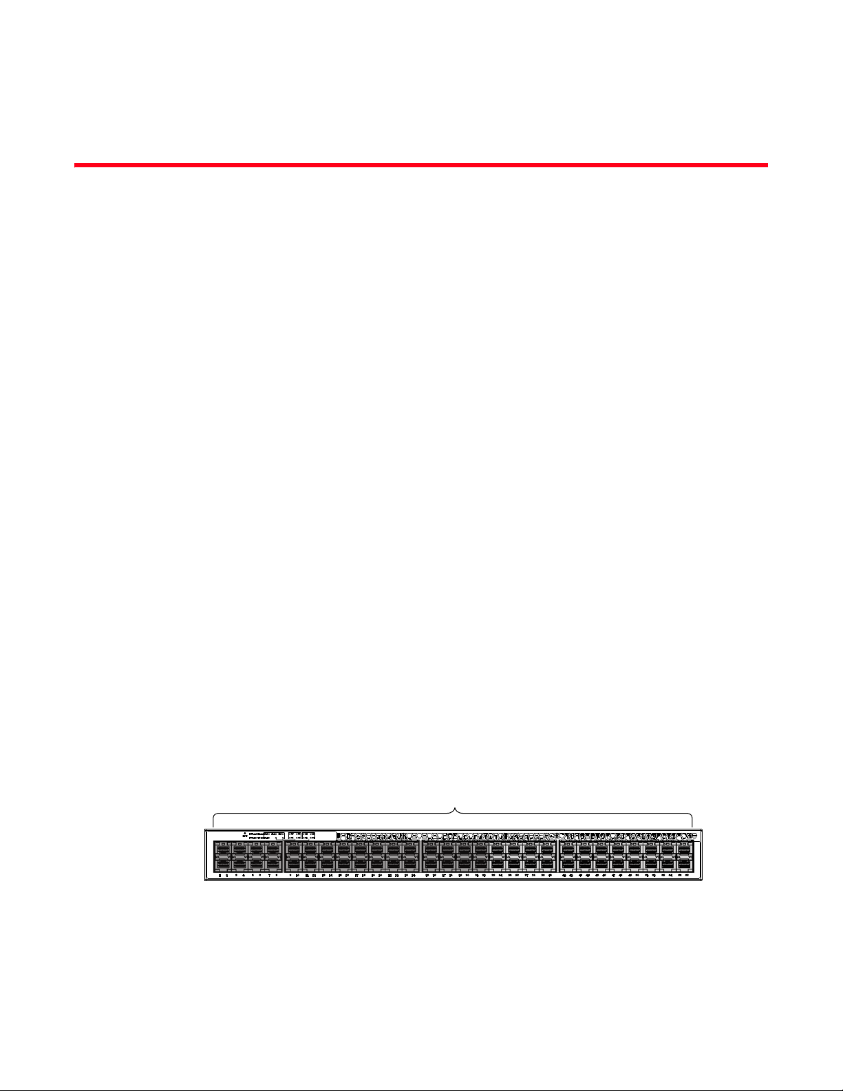
Slot 1
The Brocade ICX 6650 is a ToR (Top of Rack) Ethernet switch for campus LAN and classic Ethernet
data center environments.
Audience
This document is designed for system administrators with a working knowledge of Layer 2 and
Layer 3 switching and routing.
If you are using a Brocade Layer 3 Switch, you should be familiar with the following protocols if
applicable to your network: IP, RIP, OSPF, BGP, ISIS, PIM, and VRRP.
Supported hardware and software
This document is specific to the Brocade ICX 6650 running FastIron 7.5.00.
Brocade ICX 6650 slot and port numbering
Many CLI commands require users to enter port numbers as part of the command syntax, and
many show command outputs display port numbers. The port numbers are entered and displayed
in stack-unit/slot number/port number format. In all Brocade ICX 6650 inputs and outputs, the
stack-unit number is always 1.
The Brocade ICX 6650 contains the following slots and Ethernet ports:
• Slot 1 is located on the front of the ICX 6650 device and contains ports 1 through 56. Ports 1
through 32 are 10 GbE. Ports 33 through 56 are 1/10 GbE SFP+ ports. Refer to the following
figure.
xi
Page 14
Brocade ICX 6650 slot and port numbering
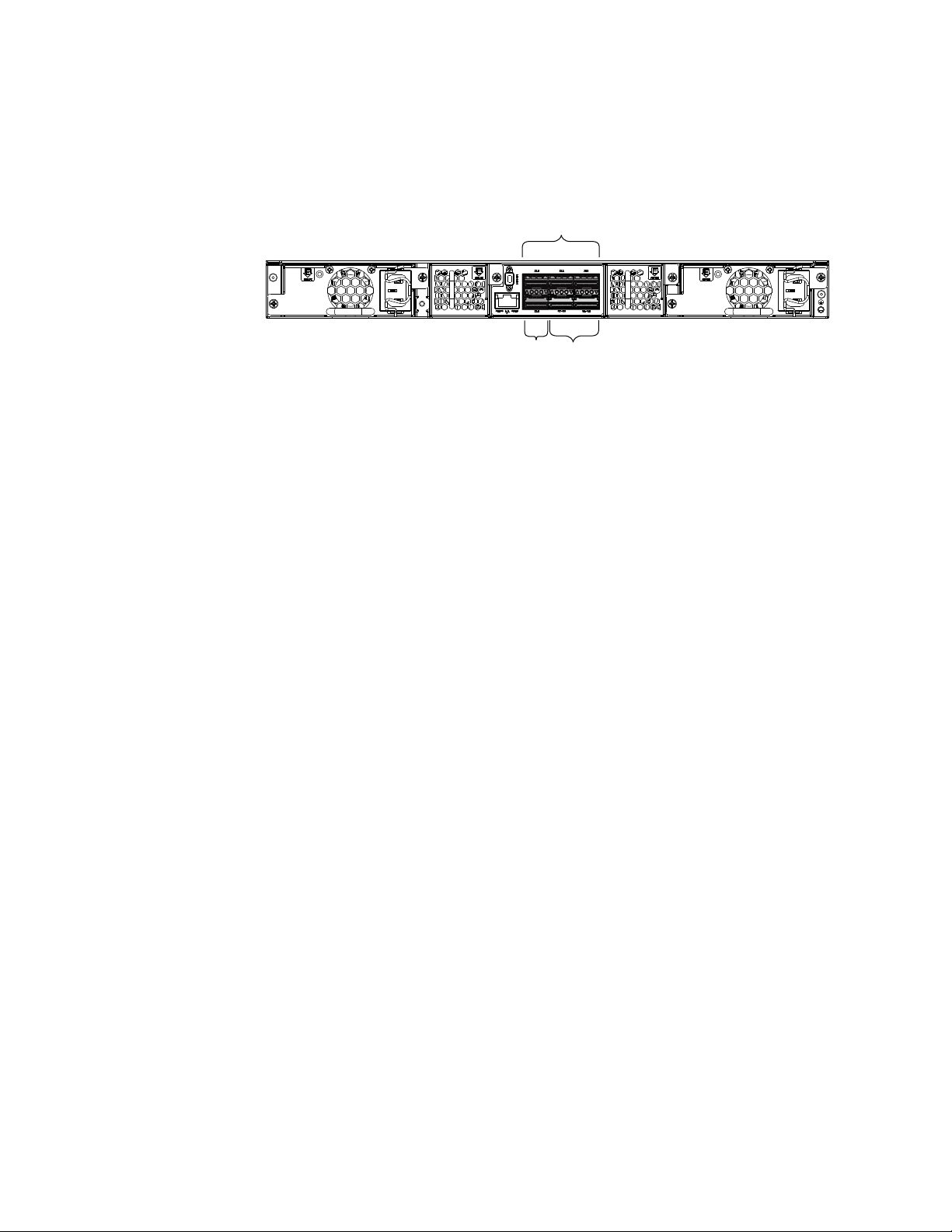
Slot 2
Slot 2 Slot 3
• Slot 2 is located on the back of the Brocade ICX 6650 device and contains ports 1 through 3
on the top row and port 4 on the bottom row. These ports are 2x40 GbE QSFP+. Refer to the
following figure.
• Slot 3 is located on the back of the Brocade ICX 6650 device and contains ports 1 through 8.
These ports are 4 x 10 GbE breakout ports and require the use of a breakout cable. Refer to
the previous figure.
How this document is organized
This document is organized to help you find the information that you want as quickly and easily as
possible.
The document contains the following components:
• “IP Configuration” on page 1
• “Base Layer 3 and Routing Protocols” on page 133
• “RIP (IPv4)” on page 141
• “RIP (IPv6)” on page 157
• “OSPF version 2 (IPv4)” on page 167
• “OSPF version 3 (IPv6)” on page 227
• “BGP (IPv4)” on page 281
• “IPv6” on page 401
• “VRRP and VRRP-E” on page 411
xii
Page 15

Document conventions
NOTE
This section describes text formatting conventions and important notice formats used in this
document.
Text formatting
The narrative-text formatting conventions that are used are as follows:
bold text Identifies command names
italic text Provides emphasis
code text Identifies CLI output
Brocade ICX 6650 slot and port numbering
Identifies the names of user-manipulated GUI elements
Identifies keywords and operands
Identifies text to enter at the GUI or CLI
Identifies variables
Identifies paths and Internet addresses
Identifies document titles
Identifies command syntax examples
For readability, command names in the narrative portions of this guide are presented in mixed
lettercase: for example, switchShow. In actual examples, command lettercase is all lowercase.
Command syntax conventions
Command syntax in this manual follows these conventions:
command Commands are printed in bold.
--option, option Command options are printed in bold.
-argument, arg Arguments.
[ ] Optional elements appear in brackets.
variable Variables are printed in italics. In the help pages, values are underlined
enclosed in angled brackets < >.
... Repeat the previous element, for example “member[;member...]”
value Fixed values following arguments are printed in plain font. For example,
--show WWN
| Boolean. Elements are exclusive. Example:
--show -mode egress | ingress
or
Notes, cautions, and warnings
The following notices and statements are used in this manual. They are listed below in order of
increasing severity of potential hazards.
A note provides a tip, guidance, or advice, emphasizes important information, or provides a
reference to related information.
Brocade ICX 6650 Layer 3 Routing Configuration Guide xiii
53-1002603-01
Page 16
Brocade ICX 6650 slot and port numbering
ATTENTION
CAUTION
DANGER
An Attention statement indicates potential damage to hardware or data.
A Caution statement alerts you to situations that can be potentially hazardous to you or cause
damage to hardware, firmware, software, or data.
A Danger statement indicates conditions or situations that can be potentially lethal or extremely
hazardous to you. Safety labels are also attached directly to products to warn of these conditions
or situations.
Notice to the reader
This document might contain references to the trademarks of the following corporations. These
trademarks are the properties of their respective companies and corporations.
These references are made for informational purposes only.
Corporation Referenced Trademarks and Products
Microsoft Corporation Windows, Windows NT, Internet Explorer
Oracle Corporation Oracle, Java
Netscape Communications Corporation Netscape
Mozilla Corporation Mozilla Firefox
Sun Microsystems, Inc. Sun, Solaris
Red Hat, Inc. Red Hat, Red Hat Network, Maximum RPM, Linux Undercover
Related publications
The following Brocade documents supplement the information in this guide:
• Brocade ICX 6650 Release Notes
• Brocade ICX 6650 Hardware Installation Guide New
• Brocade ICX 6650 Administration Guide
• Brocade ICX 6650 Platform and Layer 2 Configuration Guide
• Brocade ICX 6650 Layer 3 Routing Configuration Guide
• Brocade ICX 6650 Security Configuration Guide
• Brocade ICX 6650 IP Multicast Configuration Guide
xiv
Page 17

• Brocade ICX 6650 Diagnostic Reference
• Unified IP MIB Reference
• Ports-on-Demand Licensing for the Brocade ICX 6650
The latest versions of these guides are posted at http://www.brocade.com/ethernetproducts.
Additional information
This section lists additional Brocade and industry-specific documentation that you might find
helpful.
Brocade resources
To get up-to-the-minute information, go to http://my.brocade.com to register at no cost for a user ID
and password.
White papers, online demonstrations, and data sheets are available through the Brocade website
at:
Brocade ICX 6650 slot and port numbering
http://www.brocade.com/products-solutions/products/index.page
For additional Brocade documentation, visit the Brocade website:
http://www.brocade.com
Release notes are available on the MyBrocade website.
Other industry resources
For additional resource information, visit the Technical Committee T11 website. This website
provides interface standards for high-performance and mass storage applications for Fibre
Channel, storage management, and other applications:
http://www.t11.org
For information about the Fibre Channel industry, visit the Fibre Channel Industry Association
website:
http://www.fibrechannel.org
Getting technical help
To co n tact Technical Su p por t, g o to
http://www.brocade.com/services-support/index.page
for the latest e-mail and telephone contact information.
Brocade ICX 6650 Layer 3 Routing Configuration Guide xv
53-1002603-01
Page 18

Brocade ICX 6650 slot and port numbering
Document feedback
Quality is our first concern at Brocade and we have made every effort to ensure the accuracy and
completeness of this document. However, if you find an error or an omission, or you think that a
topic needs further development, we want to hear from you. Forward your feedback to:
documentation@brocade.com
Provide the title and version number of the document and as much detail as possible about your
comment, including the topic heading and page number and your suggestions for improvement.
xvi
Page 19

Chapter
IP Configuration
Tab le 1 lists the IP features Brocade ICX 6650 devices support. These features are supported with
the full Layer 3 software image, except where explicitly noted.
TABLE 1 Supported IP features
Feature Brocade ICX 6650
BootP/DHCP relay Yes
Specifying which IP address will be
included in a DHCP/BootP reply packet
DHCP Server Yes
DHCP Client-Based Auto-Configuration Yes
DHCP Client-Based Flash image
Auto-update
DHCP assist Yes
Equal Cost Multi Path (ECMP) load sharing Yes
IP helper Yes
Single source address for the following
packet types:
• Tel net
• TFTP
• Syslog
• SNTP
• TACACS/TACACS+
• RADIUS
• SSH
• SNMP
IPv4 point-to-point GRE IP tunnels Yes
Routes in hardware maximum:
Up to 7168 routes
Routing for directly connected IP subnets Yes
Virtual Interfaces:
Up to 512 virtual interfaces
31-bit subnet mask on point-to-point
networks
Address Resolution Protocol (ARP) Yes
Reverse Address Resolution Protocol
(RARP)
IP follow Yes
Proxy ARP Yes
1
Yes
Yes
Yes
Yes
Yes
Yes
Yes
Brocade ICX 6650 Layer 3 Routing Configuration Guide 1
53-1002603-01
Page 20

Basic IP configuration
NOTE
TABLE 1 Supported IP features (Continued)
Feature Brocade ICX 6650
Local proxy ARP Yes
Jumbo frames
• Up to 10,240 bytes
IP MTU (individual port setting) Yes
Path MTU discovery Yes
ICMP Router Discovery Protocol (IRDP) Yes
Domain Name Server (DNS) resolver Yes
The terms Layer 3 Switch and router are used interchangeably in this chapter and mean the same.
Basic IP configuration
IP is enabled by default. Basic configuration consists of adding IP addresses for Layer 3 Switches,
enabling a route exchange protocol, such as the Routing Information Protocol (RIP).
Yes
If you are configuring a Layer 3 Switch, refer to “Configuring IP addresses” on page 19 to add IP
addresses, then enable and configure the route exchange protocols, as described in other chapters
of this guide.
If you are configuring a Layer 2 Switch, refer to “Configuring the management IP address and
specifying the default gateway” on page 88 to add an IP address for management access through
the network and to specify the default gateway.
The rest of this chapter describes IP and how to configure it in more detail. Use the information in
this chapter if you need to change some of the IP parameters from their default values or you want
to view configuration information or statistics.
IP configuration overview
Brocade Layer 2 Switches and Layer 3 Switches support Internet Protocol version 4 (IPv4) and IPv6.
IP support on Brocade Layer 2 Switches consists of basic services to support management access
and access to a default gateway.
Full Layer 3 support
IP support on Brocade full Layer 3 Switches includes all of the following, in addition to a highly
configurable implementation of basic IP services including Address Resolution Protocol (ARP),
ICMP Router Discovery Protocol (IRDP), and Reverse ARP (RARP):
• Route-only support (Global configuration level only)
• Route redistribution
2 Brocade ICX 6650 Layer 3 Routing Configuration Guide
53-1002603-01
Page 21

IP configuration overview
NOTE
• Route exchange protocols:
- Routing Information Protocol (RIP)
- Open Shortest Path First (OSPF)
- Border Gateway Protocol version 4 (BGP4)
• Multicast protocols:
- Internet Group Membership Protocol (IGMP)
- Protocol Independent Multicast Dense (PIM-DM)
- Protocol Independent Multicast Sparse (PIM-SM)
• Router redundancy protocols:
- Virtual Router Redundancy Protocol Extended (VRRP-E)
- Virtual Router Redundancy Protocol (VRRP)
IP interfaces
This section describes IPv4 addresses. For information about IPv6 addresses on Brocade ICX 6650
devices, refer to “IPv6 addressing overview” section in the Brocade ICX 6650 Administration Guide.
Brocade Layer 3 Switches and Layer 2 Switches allow you to configure IP addresses. On Layer 3
Switches, IP addresses are associated with individual interfaces. On Layer 2 Switches, a single IP
address serves as the management access address for the entire device.
All Brocade Layer 3 Switches and Layer 2 Switches support configuration and display of IP
addresses in classical subnet format (for example: 192.168.1.1 255.255.255.0) and Classless
Interdomain Routing (CIDR) format (for example: 192.168.1.1/24). You can use either format when
configuring IP address information. IP addresses are displayed in classical subnet format by default
but you can change the display format to CIDR. Refer to “Changing the network mask display to
prefix format” on page 113.
Layer 3 Switches
Brocade Layer 3 Switches allow you to configure IP addresses on the following types of interfaces:
• Ethernet ports
• Virtual routing interfaces (used by VLANs to route among one another)
• Loopback interfaces
Each IP address on a Layer 3 Switch must be in a different subnet. You can have only one interface
that is in a given subnet. For example, you can configure IP addresses 192.168.1.1/24 and
192.168.2.1/24 on the same Layer 3 Switch, but you cannot configure 192.168.1.1/24 and
192.168.1.2/24 on the same Layer 3 Switch.
You can configure multiple IP addresses on the same interface.
The number of IP addresses you can configure on an individual interface depends on the Layer 3
Switch model. To display the maximum number of IP addresses and other system parameters you
can configure on a Layer 3 Switch, refer to “Displaying and modifying system parameter default
settings” section in the Brocade ICX 6650 Platform and Layer 2 Switching Configuration Guide.
Brocade ICX 6650 Layer 3 Routing Configuration Guide 3
53-1002603-01
Page 22

IP configuration overview
You can use any of the IP addresses you configure on the Layer 3 Switch for Telnet, or SNMP
access.
Layer 2 Switches
You can configure an IP address on a Brocade Layer 2 Switch for management access to the Layer
2 Switch. An IP address is required for Telnet access and SNMP access.
You also can specify the default gateway for forwarding traffic to other subnets.
4 Brocade ICX 6650 Layer 3 Routing Configuration Guide
53-1002603-01
Page 23
IP configuration overview
Incoming
Port
Outgoing
Port
Session
Table
N
Y
Fwding
Cache
N
Y
N
Y
Y
N
PBR
or
IP acc
policy
IP Route
Table
ARP
Cache
Load
Balancing
Algorithm
Mult.
Equal-
cost
Paths
Lowest
Admin.
Distance
Lowest
Metric
Static ARP
Table
RIP
OSPF
BGP4
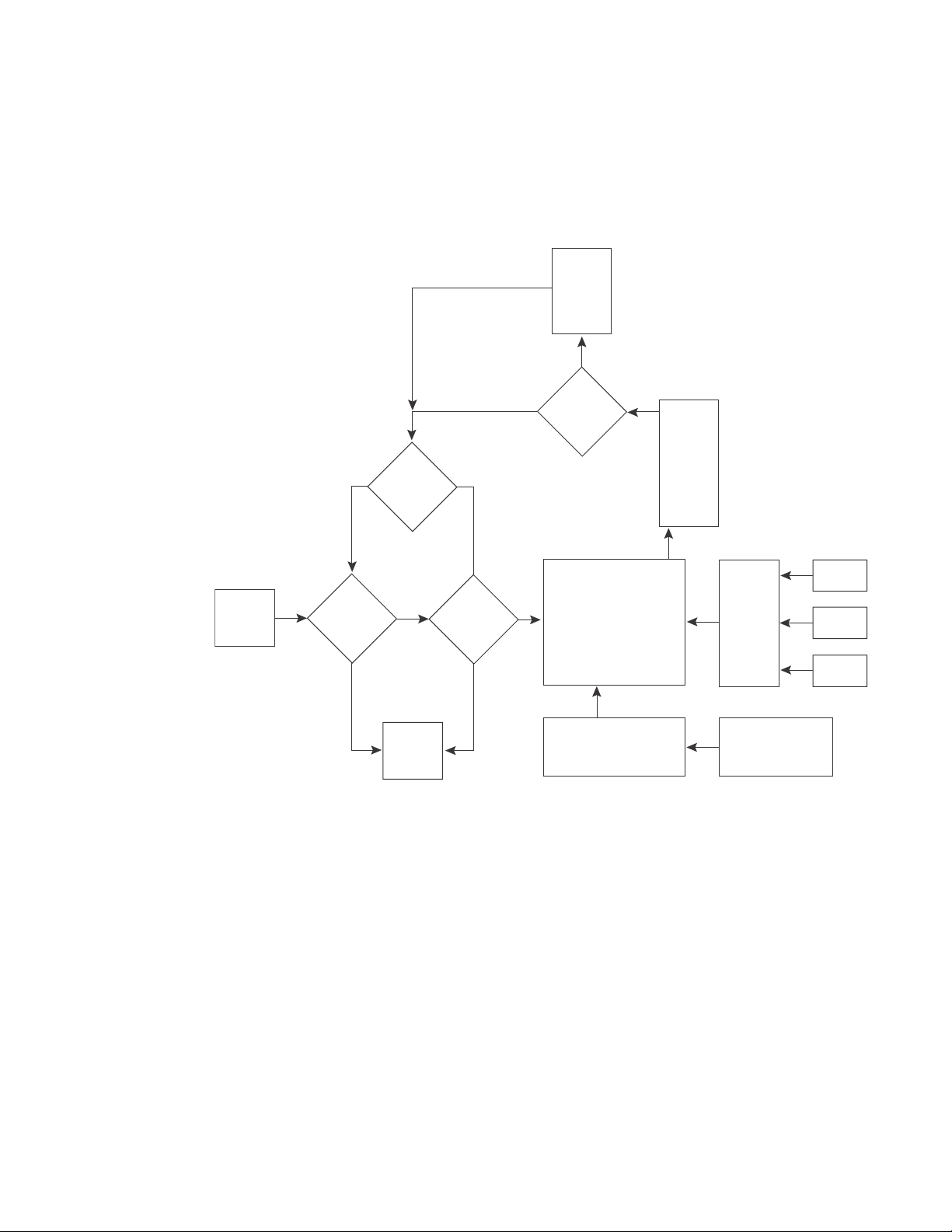
IP packet flow through a Layer 3 Switch
Figure 1 shows how an IP packet moves through a Brocade Layer 3 Switch.
FIGURE 1 IP Packet flow through a Brocade Layer 3 Switch
Figure 1 shows the following packet flow:
1. When the Layer 3 Switch receives an IP packet, the Layer 3 Switch checks for filters on the
receiving interface.
discards the packet and performs no further processing, except generating a Syslog entry and
SNMP message, if logging is enabled for the filter.
2. If the packet is not denied at the incoming interface, the Layer 3 Switch looks in the session
table for an entry that has the same source IP address and TCP or UDP port as the packet. If
the session table contains a matching entry, the Layer 3 Switch immediately forwards the
packet, by addressing it to the destination IP address and TCP or UDP port listed in the session
1
If a deny filter on the interface denies the packet, the Layer 3 Switch
table entry and sending the packet to a queue on the outgoing ports listed in the session table.
The Layer 3 Switch selects the queue based on the Quality of Service (QoS) level associated
with the session table entry.
1. The filter can be an Access Control List (ACL) or an IP access policy.
Brocade ICX 6650 Layer 3 Routing Configuration Guide 5
53-1002603-01
Page 24

IP configuration overview
IP Address MAC Address Type Age Port
1 10.95.6.102 0000.00fc.ea21 Dynamic 0 1/1/6
3. If the session table does not contain an entry that matches the packet source address and TCP
or UDP port, the Layer 3 Switch looks in the IP forwarding cache for an entry that matches the
packet destination IP address. If the forwarding cache contains a matching entry, the Layer 3
Switch forwards the packet to the IP address in the entry. The Layer 3 Switch sends the packet
to a queue on the outgoing ports listed in the forwarding cache. The Layer 3 Switch selects the
queue based on the Quality of Service (QoS) level associated with the forwarding cache entry.
4. If the IP forwarding cache does not have an entry for the packet, the Layer 3 Switch checks the
IP route table for a route to the packet destination. If the IP route table has a route, the Layer 3
Switch makes an entry in the session table or the forwarding cache, and sends the route to a
queue on the outgoing ports:
• If the running-config contains an IP access policy for the packet, the software makes an
entry in the session table. The Layer 3 Switch uses the new session table entry to forward
subsequent packets from the same source to the same destination.
• If the running-config does not contain an IP access policy for the packet, the software
creates a new entry in the forwarding cache. The Layer 3 Switch uses the new cache entry
to forward subsequent packets to the same destination.
The following sections describe the IP tables and caches:
• ARP cache and static ARP table
• IP route table
• IP forwarding cache
• Layer 4 session table
The software enables you to display these tables. You also can change the capacity of the tables on
an individual basis if needed by changing the memory allocation for the table.
ARP cache and static ARP table
The ARP cache contains entries that map IP addresses to MAC addresses. Generally, the entries
are for devices that are directly attached to the Layer 3 Switch.
An exception is an ARP entry for an interface-based static IP route that goes to a destination that is
one or more router hops away. For this type of entry, the MAC address is either the destination
device MAC address or the MAC address of the router interface that answered an ARP request on
behalf of the device, using proxy ARP.
ARP cache
The ARP cache can contain dynamic (learned) entries and static (user-configured) entries. The
software places a dynamic entry in the ARP cache when the Layer 3 Switch learns a device MAC
address from an ARP request or ARP reply from the device.
The software can learn an entry when the Layer 2 Switch or Layer 3 Switch receives an ARP request
from another IP forwarding device or an ARP reply. Here is an example of a dynamic entry:
Each entry contains the destination device IP address and MAC address.
6 Brocade ICX 6650 Layer 3 Routing Configuration Guide
53-1002603-01
Page 25

IP configuration overview
NOTE
NOTE
Static ARP table
In addition to the ARP cache, Layer 3 Switches have a static ARP table. Entries in the static ARP
table are user-configured. You can add entries to the static ARP table regardless of whether or not
the device the entry is for is connected to the Layer 3 Switch.
Layer 3 Switches have a static ARP table. Layer 2 Switches do not.
The software places an entry from the static ARP table into the ARP cache when the entry interface
comes up.
Here is an example of a static ARP entry.
No. IP Address MAC Address Type Age Port Status
1 192.168.6.111 0000.003b.d210 Static 0 1/1/1 Valid
Each entry lists the information you specified when you created the entry.
Displaying ARP entries
To display ARP entries, refer to the following sections:
• “Displaying the ARP cache” on page 118 – Layer 3 Switch
• “Displaying the static ARP table” on page 120 – Layer 3 Switch only
• “Displaying ARP entries” on page 129 – Layer 2 Switch
To configure other ARP parameters, refer to the following sections:
• “ARP parameter configuration” on page 35 – Layer 3 Switch only
To increase the size of the ARP cache and static ARP table, refer to the following:
• For dynamic entries, refer to the section “Displaying and modifying system parameter default
settings” section in the Brocade ICX 6650 Platform and Layer 2 Switching Configuration
Guide. The ip-arp parameter controls the ARP cache size.
• Static entries, “Changing the maximum number of entries the static ARP table can hold” on
page 40 (Layer 3 Switches only). The ip-static-arp parameter controls the static ARP table size.
IP route table
The IP route table contains paths to IP destinations.
Layer 2 Switches do not have an IP route table. A Layer 2 Switch sends all packets addressed to
another subnet to the default gateway, which you specify when you configure the basic IP
information on the Layer 2 Switch.
The IP route table can receive the paths from the following sources:
• A directly-connected destination, which means there are no router hops to the destination
• A static IP route, which is a user-configured route
• A route learned through RIP
• A route learned through OSPF
• A route learned through BGP4
Brocade ICX 6650 Layer 3 Routing Configuration Guide 7
53-1002603-01
Page 26

IP configuration overview
Destination NetMask Gateway Port Cost Type
10.1.0.0 255.255.0.0 10.1.1.2 1/1/1 2 R
The IP route table contains the best path to a destination:
• When the software receives paths from more than one of the sources listed above, the
software compares the administrative distance of each path and selects the path with the
lowest administrative distance. The administrative distance is a protocol-independent value
from 1 through 255.
• When the software receives two or more best paths from the same source and the paths have
the same metric (cost), the software can load share traffic among the paths based on
destination host or network address (based on the configuration and the Layer 3 Switch
model).
Here is an example of an entry in the IP route table.
Each IP route table entry contains the destination IP address and subnet mask and the IP address
of the next-hop router interface to the destination. Each entry also indicates the port attached to
the destination or the next-hop to the destination, the route IP metric (cost), and the type. The type
indicates how the IP route table received the route:
• To display the IP route table, refer to “Displaying the IP route table” on page 122 (Layer 3
Switch only).
• To configure a static IP route, refer to “Static routes configuration” on page 45 (Layer 3 Switch
only).
• To clear a route from the IP route table, refer to “Clearing IP routes” on page 124 (Layer 3
Switch only).
• To increase the size of the IP route table for learned and static routes, refer to the section
“Displaying and modifying system parameter default settings” section in the Brocade ICX 6650
Platform and Layer 2 Switching Configuration Guide:
- For learned routes, modify the ip-route parameter.
- For static routes, modify the ip-static-route parameter.
IP forwarding cache
The IP forwarding cache provides a fast-path mechanism for forwarding IP packets. The cache
contains entries for IP destinations. When a Brocade Layer 3 Switch has completed processing and
addressing for a packet and is ready to forward the packet, the device checks the IP forwarding
cache for an entry to the packet destination:
• If the cache contains an entry with the destination IP address, the device uses the information
in the entry to forward the packet out the ports listed in the entry. The destination IP address is
the address of the packet final destination. The port numbers are the ports through which the
destination can be reached.
• If the cache does not contain an entry and the traffic does not qualify for an entry in the
session table instead, the software can create an entry in the forwarding cache.
Each entry in the IP forwarding cache has an age timer. If the entry remains unused for ten
minutes, the software removes the entry. The age timer is not configurable.
Here is an example of an entry in the IP forwarding cache.
8 Brocade ICX 6650 Layer 3 Routing Configuration Guide
53-1002603-01
Page 27

IP configuration overview
NOTE
IP Address Next Hop MAC Type Port Vlan Pri
1 192.168.1.11 DIRECT 0000.0000.0000 PU n/a 0
Each IP forwarding cache entry contains the IP address of the destination, and the IP address and
MAC address of the next-hop router interface to the destination. If the destination is actually an
interface configured on the Layer 3 Switch itself, as shown here, then next-hop information
indicates this. The port through which the destination is reached is also listed, as well as the VLAN
and Layer 4 QoS priority associated with the destination if applicable.
To display the IP forwarding cache, refer to “Displaying the forwarding cache” on page 121.
You cannot add static entries to the IP forwarding cache, although you can increase the number of
entries the cache can contain. Refer to the section “Displaying and modifying system parameter
default settings” section in the Brocade ICX 6650 Platform and Layer 2 Switching Configuration
Guide.
Layer 4 session table
The Layer 4 session provides a fast path for forwarding packets. A session is an entry that contains
complete Layer 3 and Layer 4 information for a flow of traffic. Layer 3 information includes the
source and destination IP addresses. Layer 4 information includes the source and destination TCP
and UDP ports. For comparison, the IP forwarding cache contains the Layer 3 destination address
but does not contain the other source and destination address information of a Layer 4 session
table entry.
The Layer 2 Switch or Layer 3 Switch selects the session table instead of the IP forwarding table for
fast-path forwarding for the following features:
• Layer 4 Quality-of-Service (QoS) policies
• IP access policies
To increase the size of the session table, refer to the section “Displaying and modifying system
parameter default settings” section in the Brocade ICX 6650 Platform and Layer 2 Switching
Configuration Guide. The ip-qos-session parameter controls the size of the session table.
IP route exchange protocols
Brocade Layer 3 Switches support the following IP route exchange protocols:
• Routing Information Protocol (RIP)
• Open Shortest Path First (OSPF)
• Border Gateway Protocol version 4 (BGP4)
All these protocols provide routes to the IP route table. You can use one or more of these protocols,
in any combination. The protocols are disabled by default. For configuration information, refer to
the following:
• Chapter 3, “RIP (IPv4)”
• Chapter 5, “OSPF version 2 (IPv4)”
• Chapter 7, “BGP (IPv4)”
Brocade ICX 6650 Layer 3 Routing Configuration Guide 9
53-1002603-01
Page 28

IP configuration overview
NOTE
IP multicast protocols
Brocade Layer 3 Switches also support the following Internet Group Membership Protocol (IGMP)
based IP multicast protocols:
• Protocol Independent Multicast – Dense mode (PIM-DM)
• Protocol Independent Multicast – Sparse mode (PIM-SM)
For configuration information, refer to the Brocade ICX 6650 IP Multicast Configuration Guide. .
Brocade Layer 2 Switches support IGMP and can forward IP multicast packets. For more information
see, Chapter 2, “IP Multicast Reduction” in the Brocade ICX 6650 IP Mulitcast Configuration Guide.
IP interface redundancy protocols
You can configure a Brocade Layer 3 Switch to back up an IP interface configured on another
Brocade Layer 3 Switch. If the link for the backed up interface becomes unavailable, the other
Layer 3 Switch can continue service for the interface. This feature is especially useful for providing
a backup to a network default gateway.
Brocade Layer 3 Switches support the following IP interface redundancy protocols:
• Virtual Router Redundancy Protocol (VRRP) – A standard router redundancy protocol based on
RFC 2338. You can use VRRP to configure Brocade Layer 3 Switches and third-party routers to
back up IP interfaces on other Brocade Layer 3 Switches or third-party routers.
• Virtual Router Redundancy Protocol Extended (VRRP-E) – A Brocade extension to standard
VRRP that adds additional features and overcomes limitations in standard VRRP. You can use
VRRP-E only on Brocade Layer 3 Switches.
For configuration information, refer to the Chapter 9, “VRRP and VRRP-E”.
ACLs and IP access policies
Brocade Layer 3 Switches provide two mechanisms for filtering IP traffic:
• Access Control Lists (ACLs)
• IP access policies
Both methods allow you to filter packets based on Layer 3 and Layer 4 source and destination
information.
ACLs also provide great flexibility by providing the input to various other filtering mechanisms such
as route maps, which are used by BGP4.
IP access policies allow you to configure QoS based on sessions (Layer 4 traffic flows).
Only one of these filtering mechanisms can be enabled on a Brocade device at a time. Brocade
devices can store forwarding information for both methods of filtering in the session table.
For configuration information, see the Chapter, “Rule-Based IP ACLs” in the Brocade ICX 6650
Security Configuration Guide.
10 Brocade ICX 6650 Layer 3 Routing Configuration Guide
53-1002603-01
Page 29

Basic IP parameters and defaults – Layer 3 Switches
NOTE
NOTE
Basic IP parameters and defaults – Layer 3 Switches
IP is enabled by default. The following IP-based protocols are all disabled by default:
• Routing protocols:
- Routing Information Protocol (RIP) – refer to Chapter 3, “RIP (IPv4)”
- Open Shortest Path First (OSPF) – refer to Chapter 5, “OSPF version 2 (IPv4)”
- Border Gateway Protocol version 4 (BGP4) – refer to Chapter 7, “BGP (IPv4)”
• Multicast protocols:
- Internet Group Membership Protocol (IGMP)
- Protocol Independent Multicast Dense (PIM-DM)
- Protocol Independent Multicast Sparse (PIM-SM)
For more information, see the Brocade ICX 6650 IP Mulitcast Configuration Guide.
• Router redundancy protocols:
- Virtual Router Redundancy Protocol Extended (VRRP-E) – refer to Chapter 9, “VRRP and
VRRP-E”
- Virtual Router Redundancy Protocol (VRRP) – refer to Chapter 9, “VRRP and VRRP-E”
The following tables list the Layer 3 Switch IP parameters, their default values, and where to find
configuration information.
For information about parameters in other protocols based on IP, such as RIP, OSPF, and so on, refer
to the configuration chapters for those protocols.
When parameter changes take effect
Most IP parameters described in this chapter are dynamic. They take effect immediately, as soon
as you enter the CLI command. You can verify that a dynamic change has taken effect by displaying
the running-config. To display the running-config, enter the show running-config or write terminal
command at any CLI prompt.
To save a configuration change permanently so that the change remains in effect following a
system reset or software reload, save the change to the startup-config file:
• To save configuration changes to the startup-config file, enter the write memory command
from the Privileged EXEC level of any configuration level of the CLI.
Changes to memory allocation require you to reload the software after you save the changes to the
startup-config file. When reloading the software is required to complete a configuration change
described in this chapter, the procedure that describes the configuration change includes a step
for reloading the software.
IP global parameters – Layer 3 Switches
Tab le 2 lists the IP global parameters for Layer 3 Switches.
Brocade ICX 6650 Layer 3 Routing Configuration Guide 11
53-1002603-01
Page 30

Basic IP parameters and defaults – Layer 3 Switches
TABLE 2 IP global parameters – Layer 3 Switches
Parameter Description Default For more
information
IP state The Internet Protocol, version 4 Enabled
NOTE: You can not
IP address and
mask notation
Format for displaying an IP address and its network
mask information. You can enable one of the
following:
Class-based
NOTE: Changing this
• Class-based format; example: 192.168.1.1
255.255.255.0
• Classless Interdomain Routing (CIDR) format;
example: 192.168.1.1/24
Router ID The value that routers use to identify themselves to
other routers when exchanging route information.
OSPF and BGP4 use router IDs to identify routers.
RIP does not use the router ID.
Maximum
Transmission
Unit (MTU)
Address
Resolution
Protocol (ARP)
ARP rate
limiting
ARP age The amount of time the device keeps a MAC address
Proxy ARP An IP mechanism a router can use to answer an ARP
The maximum length an Ethernet packet can be
without being fragmented.
A standard IP mechanism that routers use to learn
the Media Access Control (MAC) address of a device
on the network. The router sends the IP address of a
device in the ARP request and receives the device
MAC address in an ARP reply.
Lets you specify a maximum number of ARP packets
the device will accept each second. If the device
receives more ARP packets than you specify, the
device drops additional ARP packets for the
remainder of the one-second interval.
learned through ARP in the device ARP cache. The
device resets the timer to zero each time the ARP
entry is refreshed and removes the entry if the timer
reaches the ARP age.
NOTE: You also can change the ARP age on an
individual interface basis. Refer to Tabl e 3
on page 15.
request on behalf of a host, by replying with the
router own MAC address instead of the host.
The IP address
configured on the
lowest-numbered
loopback interface.
If no loopback interface
is configured, then the
lowest-numbered IP
address configured on
the device.
1500 bytes for Ethernet
II encapsulation
1492 bytes for SNAP
encapsulation
Enabled page 35
Disabled page 36
Ten min u tes page 37
Disabled page 38
n/a
disable IP.
page 113
parameter
affects the
display of IP
addresses, but
you can enter
addresses in
either format
regardless of the
display setting.
page 31
page 28
12 Brocade ICX 6650 Layer 3 Routing Configuration Guide
53-1002603-01
Page 31

Basic IP parameters and defaults – Layer 3 Switches
TABLE 2 IP global parameters – Layer 3 Switches (Continued)
Parameter Description Default For more
information
Static ARP
entries
Time to Live
(TTL)
Directed
broadcast
forwarding
Directed
broadcast
mode
Source-routed
packet
forwarding
Internet Control
Message
Protocol (ICMP)
messages
ICMP Router
Discovery
Protocol (IRDP)
Reverse ARP
(RARP)
An ARP entry you place in the static ARP table. Static
entries do not age out.
The maximum number of routers (hops) through
which a packet can pass before being discarded.
Each router decreases a packet TTL by 1 before
forwarding the packet. If decreasing the TTL causes
the TTL to be 0, the router drops the packet instead
of forwarding it.
A directed broadcast is a packet containing all ones
(or in some cases, all zeros) in the host portion of
the destination IP address. When a router forwards
such a broadcast, it sends a copy of the packet out
each of its enabled IP interfaces.
NOTE: You also can enable or disable this
parameter on an individual interface basis.
Refer to Tabl e 3 on page 15.
The packet format the router treats as a directed
broadcast. The following formats can be directed
broadcast:
• All ones in the host portion of the packet
destination address.
• All zeroes in the host portion of the packet
destination address.
A source-routed packet contains a list of IP
addresses through which the packet must pass to
reach its destination.
The Brocade Layer 3 Switch can send the following
types of ICMP messages:
• Echo messages (ping messages)
• Destination Unreachable messages
An IP protocol a router can use to advertise the IP
addresses of its router interfaces to directly
attached hosts. You can enable or disable the
protocol, and change the following protocol
parameters:
• Forwarding method (broadcast or multicast)
• Hold time
• Maximum advertisement interval
• Minimum advertisement interval
• Router preference level
NOTE: You also can enable or disable IRDP and
configure the parameters on an individual
interface basis. Refer to Tabl e 3 on page 15.
An IP mechanism a host can use to request an IP
address from a directly attached router when the
host boots.
No entries page 39
64 hops page 41
Disabled page 41
All ones
NOTE: If you enable
all-zeroes
directed
broadcasts,
all-ones directed
broadcasts
remain enabled.
Enabled page 41
Enabled page 43
Disabled page 58
Enabled page 61
page 42
Brocade ICX 6650 Layer 3 Routing Configuration Guide 13
53-1002603-01
Page 32

Basic IP parameters and defaults – Layer 3 Switches
TABLE 2 IP global parameters – Layer 3 Switches (Continued)
Parameter Description Default For more
information
Static RARP
entries
Maximum
BootP relay
hops
Domain name
for Domain
Name Server
(DNS) resolver
DNS default
gateway
addresses
IP load sharing A Brocade feature that enables the router to balance
Maximum IP
load sharing
paths
Origination of
default routes
An IP address you place in the RARP table for RARP
requests from hosts.
NOTE: You must enter the RARP entries manually.
The Layer 3 Switch does not have a
mechanism for learning or dynamically
generating RARP entries.
The maximum number of hops away a BootP ser ver
can be located from a router and still be used by the
router clients for network booting.
A domain name (example: brocade.router.com) you
can use in place of an IP address for certain
operations such as IP pings, trace routes, and Telnet
management connections to the router.
A list of gateways attached to the router through
which clients attached to the router can reach DNSs.
traffic to a specific destination across multiple
equal-cost paths.
IP load sharing uses a hashing algorithm based on
the source IP address, destination IP address,
protocol field in the IP header, TCP, and UDP
information.
NOTE: Load sharing is sometimes called Equal Cost
Multi Path (ECMP).
The maximum number of equal-cost paths across
which the Layer 3 Switch is allowed to distribute
traffic.
You can enable a router to originate default routes
for the following route exchange protocols, on an
individual protocol basis:
• RIP
• OSPF
• BGP4
Default network
route
The router uses the default network route if the IP
route table does not contain a route to the
destination and also does not contain an explicit
default route (0.0.0.0 0.0.0.0 or 0.0.0.0/0).
No entries page 62
Four page 67
None configured page 25
None configured page 25
Enabled page 55
Four page 58
Disabled page 144
page 178
page 291
None configured page 54
14 Brocade ICX 6650 Layer 3 Routing Configuration Guide
53-1002603-01
Page 33

Basic IP parameters and defaults – Layer 3 Switches
TABLE 2 IP global parameters – Layer 3 Switches (Continued)
Parameter Description Default For more
information
Static route An IP route you place in the IP route table. No entries page 45
Source
interface
The IP address the router uses as the source
address for Telnet, RADIUS, or TACACS/TACACS+
packets originated by the router. The router can
select the source address based on either of the
following:
The lowest-numbered IP
address on the interface
the packet is sent on.
page 31
• The lowest-numbered IP address on the
interface the packet is sent on.
• The lowest-numbered IP address on a specific
interface. The address is used as the source for
all packets of the specified type regardless of
interface the packet is sent on.
IP interface parameters – Layer 3 Switches
Tab le 3 lists the interface-level IP parameters for Layer 3 Switches.
TABLE 3 IP interface parameters – Layer 3 Switches
Parameter Description Default For more
information
IP state The Internet Protocol, version 4 Enabled
NOTE: You can not
IP address A Layer 3 network interface address
NOTE: Layer 2 Switches have a single IP address
used for management access to the entire
device. Layer 3 Switches have separate IP
addresses on individual interfaces.
Encapsulation type The format of the packets in which the router
encapsulates IP datagrams. The encapsulation
format can be one of the following:
None configured
Ethernet II page 28
• Ethernet II
• SNAP
Maximum
Transmission Unit
(MTU)
ARP age Locally overrides the global setting. Refer to
Metric A numeric cost the router adds to RIP routes
Directed broadcast
forwarding
ICMP Router
Discovery Protocol
(IRDP)
The maximum length (number of bytes) of an
encapsulated IP datagram the router can forward.
Tab le 2 on page 12.
learned on the interface. This parameter applies
only to RIP routes.
Locally overrides the global setting. Refer to
Tab le 2 on page 12.
Locally overrides the global IRDP settings. Refer to
Tab le 2 on page 12.
1500 for Ethernet II
encapsulated packets
1492 for SNAP
encapsulated packets
Ten min u tes page 37
1 (one) page 144
Disabled page 41
Disabled page 60
disable IP.
n/a
1
page 19
page 30
Brocade ICX 6650 Layer 3 Routing Configuration Guide 15
53-1002603-01
Page 34

Basic IP parameters and defaults – Layer 3 Switches
TABLE 3 IP interface parameters – Layer 3 Switches (Continued)
Parameter Description Default For more
information
DHCP gateway
stamp
DHCP Client-Based
Auto-Configuration
DHCP Server All FastIron devices can be configured to function
UDP broadcast
forwarding
IP helper address The IP address of a UDP application server (such
The router can assist DHCP/BootP Discovery
packets from one subnet to reach DHCP/BootP
servers on a different subnet by placing the IP
address of the router interface that receives the
request in the request packet Gateway field.
You can override the default and specify the IP
address to use for the Gateway field in the
packets.
NOTE: UDP broadcast forwarding for client
DHCP/BootP requests (bootps) must be
enabled (this is enabled by default) and
you must configure an IP helper address
(the server IP address or a directed
broadcast to the server subnet) on the port
connected to the client.
Allows the switch to obtain IP addresses from a
DHCP host automatically, for either a specified
(leased) or infinite period of time.
as DHCP servers.
The router can forward UDP broadcast packets for
UDP applications such as BootP. By forwarding the
UDP broadcasts, the router enables clients on one
subnet to find servers attached to other subnets.
NOTE: To completely enable a client UDP
application request to find a server on
another subnet, you must configure an IP
helper address consisting of the server IP
address or the directed broadcast address
for the subnet that contains the server. See
the next row.
as a BootP or DHCP server) or a directed broadcast
address. IP helper addresses allow the router to
forward requests for certain UDP applications from
a client on one subnet to a server on another
subnet.
The lowest-numbered IP
address on the interface
that receives the
request
Enabled page 80
Disabled page 67
The router helps forward
broadcasts for the
following UDP
application protocols:
page 66
page 63
• bootps
• dns
• netbios-dgm
• netbios-ns
• tacacs
• tftp
• time
None configured page 64
1. Some devices have a factory default, used for troubleshooting during installation. For Layer 3 Switches, the
address is on module 1 port 1 (or 1/1/1).
16 Brocade ICX 6650 Layer 3 Routing Configuration Guide
53-1002603-01
Page 35

Basic IP parameters and defaults – Layer 2 Switches
NOTE
Basic IP parameters and defaults – Layer 2 Switches
IP is enabled by default. The following tables list the Layer 2 Switch IP parameters, their default
values, and where to find configuration information.
Brocade Layer 2 Switches also provide IP multicast forwarding, which is enabled by default. For more
information about this feature, refer to the Brocade ICX 6650 IP Multicast Configuration Guide.
IP global parameters – Layer 2 Switches
Tab le 4 lists the IP global parameters for Layer 2 Switches.
TABLE 4 IP global parameters – Layer 2 Switches
Parameter Description Default For more
information
IP address
and mask
notation
Format for displaying an IP address and its network
mask information. You can enable one of the
following:
• Class-based format; example: 192.168.1.1
255.255.255.0
• Classless Interdomain Routing (CIDR) format;
example: 192.168.1.1/24
IP address A Layer 3 network interface address
NOTE: Layer 2 Switches have a single IP address
used for management access to the entire
device. Layer 3 Switches have separate IP
addresses on individual interfaces.
Default
gateway
Address
Resolution
Protocol (ARP)
ARP age The amount of time the device keeps a MAC address
Time to Live
(TTL)
The IP address of a locally attached router (or a router
attached to the Layer 2 Switch by bridges or other
Layer 2 Switches). The Layer 2 Switch and clients
attached to it use the default gateway to
communicate with devices on other subnets.
A standard IP mechanism that networking devices
use to learn the Media Access Control (MAC) address
of another device on the network. The Layer 2 Switch
sends the IP address of a device in the ARP request
and receives the device MAC address in an ARP reply.
learned through ARP in the device ARP cache. The
device resets the timer to zero each time the ARP
entry is refreshed and removes the entry if the timer
reaches the ARP age.
The maximum number of routers (hops) through
which a packet can pass before being discarded.
Each router decreases a packet TTL by 1 before
forwarding the packet. If decreasing the TTL causes
the TTL to be 0, the router drops the packet instead of
forwarding it.
Class-based
NOTE: Changing this
parameter affects
the display of IP
addresses, but you
can enter
addresses in either
format regardless
of the display
setting.
None configured
None configured page 88
Enabled
NOTE: You cannot disable
ARP.
Ten min u tes
NOTE: You cannot change
the ARP age on
Layer 2 Switches.
64 hops page 90
1
page 113
page 88
n/a
n/a
Brocade ICX 6650 Layer 3 Routing Configuration Guide 17
53-1002603-01
Page 36

Basic IP parameters and defaults – Layer 2 Switches
TABLE 4 IP global parameters – Layer 2 Switches (Continued)
Parameter Description Default For more
information
Domain name
for Domain
Name Server
(DNS) resolver
DNS default
gateway
addresses
Source
interface
DHCP gateway
stamp
DHCP
Client-Based
Auto-Configura
tion
A domain name (example: brocade.router.com) you
can use in place of an IP address for certain
operations such as IP pings, trace routes, and Telnet
management connections to the router.
A list of gateways attached to the router through
which clients attached to the router can reach DNSs.
The IP address the Layer 2 Switch uses as the source
address for Telnet, RADIUS, or TACACS/TACACS+
packets originated by the router. The Layer 2 Switch
uses its management IP address as the source
address for these packets.
The device can assist DHCP/BootP Discovery packets
from one subnet to reach DHCP/BootP servers on a
different subnet by placing the IP address of the
router interface that forwards the packet in the
packet Gateway field.
You can specify up to 32 gateway lists. A gateway list
contains up to eight gateway IP addresses. You
activate DHCP assistance by associating a gateway
list with a port.
When you configure multiple IP addresses in a
gateway list, the Layer 2 Switch inserts the addresses
into the DHCP Discovery packets in a round robin
fashion.
Allows the switch to obtain IP addresses from a DHCP
host automatically, for either a specified (leased) or
infinite period of time.
None configured page 89
None configured page 89
The management IP
address of the Layer 2
Switch.
NOTE: This parameter is
not configurable
on Layer 2
Switches.
None configured page 94
Enabled page 80
n/a
1. Some devices have a factory default, used for troubleshooting during installation. For Layer 3 Switches, the
address is on port 1 (or 1/1/1).
18 Brocade ICX 6650 Layer 3 Routing Configuration Guide
53-1002603-01
Page 37

Configuring IP parameters – Layer 3 Switches
NOTE
NOTE
Interface IP parameters – Layer 2 Switches
Tab le 5 lists the interface-level IP parameters for Layer 2 Switches.
TABLE 5 Interface IP parameters – Layer 2 Switches
Parameter Description Default For more
information
DHCP
gateway
stamp
You can configure a list of DHCP stamp addresses for a port.
When the port receives a DHCP/BootP Discovery packet from a
client, the port places the IP addresses in the gateway list into
the packet Gateway field.
Configuring IP parameters – Layer 3 Switches
The following sections describe how to configure IP parameters. Some parameters can be
configured globally while others can be configured on individual interfaces. Some parameters can
be configured globally and overridden for individual interfaces.
This section describes how to configure IP parameters for Layer 3 Switches. For IP configuration
information for Layer 2 Switches, refer to “Configuring IP parameters – Layer 2 Switches” on
page 88.
Configuring IP addresses
You can configure an IP address on the following types of Layer 3 Switch interfaces:
• Ethernet port
• Virtual routing interface (also called a Virtual Ethernet or “VE”)
• Loopback interface
None configured page 94
By default, you can configure up to 24 IP addresses on each interface.
You can increase this amount to up to 128 IP subnet addresses per port by increasing the size of
the ip-subnet-port table.
Refer to the section “Displaying system parameter default values” in the Brocade ICX 6650
Platform and Layer 2 Switching Configuration Guide.
Once you configure a virtual routing interface on a VLAN, you cannot configure Layer 3 interface
parameters on individual ports. Instead, you must configure the parameters on the virtual routing
interface itself.
Brocade ICX 6650 Layer 3 Routing Configuration Guide 19
53-1002603-01
Page 38

Configuring IP parameters – Layer 3 Switches
NOTE
NOTE
Brocade devices support both classical IP network masks (Class A, B, and C subnet masks, and so
on) and Classless Interdomain Routing (CIDR) network prefix masks:
• To enter a classical network mask, enter the mask in IP address format. For example, enter
“192.168.22.99 255.255.255.0” for an IP address with a Class-C subnet mask.
• To enter a prefix network mask, enter a forward slash ( / ) and the number of bits in the mask
immediately after the IP address. For example, enter “192.168.22.99/24” for an IP address
that has a network mask with 24 significant bits (ones).
By default, the CLI displays network masks in classical IP address format (example:
255.255.255.0). You can change the display to prefix format. Refer to “Changing the network mask
display to prefix format” on page 113.
Assigning an IP address to an Ethernet port
To assign an IP address to port 1/1/1, enter the following commands.
Brocade(config)# interface ethernet 1/1/1
Brocade(config-if-e10000-1/1/1)# ip address 192.168.6.1 255.255.255.0
You also can enter the IP address and mask in CIDR format, as follows.
Brocade(config-if-e10000-1/1/1)# ip address 192.168.6.1/24
Syntax: [no] ip address ip-addr ip-mask [ospf-ignore | ospf-passive | secondary]
or
Syntax: [no] ip address ip-addr/mask-bits [ospf-ignore | ospf-passive | secondary]
The ospf-ignore | ospf-passive parameters modify the Layer 3 Switch defaults for adjacency
formation and interface advertisement. Use one of these parameters if you are configuring multiple
IP subnet addresses on the interface but you want to prevent OSPF from running on some of the
subnets:
• ospf-passive – This option disables adjacency formation with OSPF neighbors. By default,
when OSPF is enabled on an interface, the software forms OSPF router adjacencies between
each primary IP address on the interface and the OSPF neighbor attached to the interface.
• ospf-ignore – This option disables OSPF adjacency formation and also disables advertisement
of the interface into OSPF. The subnet is completely ignored by OSPF.
The ospf-passive option disables adjacency formation but does not disable advertisement of the
interface into OSPF. To disable advertisement in addition to disabling adjacency formation, you must
use the ospf-ignore option.
Use the secondary parameter if you have already configured an IP address within the same subnet
on the interface.
When you configure more than one address in the same subnet, all but the first address are
secondary addresses and do not form OSPF adjacencies.
20 Brocade ICX 6650 Layer 3 Routing Configuration Guide
53-1002603-01
Page 39

Configuring IP parameters – Layer 3 Switches
NOTE
NOTE
NOTE
All physical IP interfaces on Brocade Layer 3 devices share the same MAC address. For this reason,
if more than one connection is made between two devices, one of which is a Brocade Layer 3 device,
Brocade recommends the use of virtual interfaces. It is not recommended to connect two or more
physical IP interfaces between two routers.
Assigning an IP address to a loopback interface
Loopback interfaces are always up, regardless of the states of physical interfaces. They can add
stability to the network because they are not subject to route flap problems that can occur due to
unstable links between a Layer 3 Switch and other devices. You can configure up to eight loopback
interfaces on a Chassis Layer 3 Switch .
You can add up to 24 IP addresses to each loopback interface.
If you configure the Brocade Layer 3 Switch to use a loopback interface to communicate with a BGP4
neighbor, you also must configure a loopback interface on the neighbor and configure the neighbor
to use that loopback interface to communicate with the Brocade Layer 3 Switch. Refer to “Adding a
loopback interface” on page 292.
To add a loopback interface, enter commands such as those shown in the following example.
Brocade(config-bgp-router)# exit
Brocade(config)# interface loopback 1
Brocade(config-lbif-1)# ip address 10.0.0.1/24
Syntax: interface loopback num
The num parameter specifies the virtual interface number. You can specify from 1 to the maximum
number of virtual interfaces supported on the device. To display the maximum number of virtual
interfaces supported on the device, enter the show default values command. The maximum is
listed in the System Parameters section, in the Current column of the virtual-interface row.
Refer to the syntax description in “Assigning an IP address to an Ethernet port” on page 20.
Assigning an IP address to a virtual interface
A virtual interface is a logical port associated with a Layer 3 Virtual LAN (VLAN) configured on a
Layer 3 Switch. You can configure routing parameters on the virtual interface to enable the Layer 3
Switch to route protocol traffic from one Layer 3 VLAN to the other, without using an external
1
router.
You can configure IP routing interface parameters on a virtual interface. This section describes how
to configure an IP address on a virtual interface. Other sections in this chapter that describe how to
configure interface parameters also apply to virtual interfaces.
The Layer 3 Switch uses the lowest MAC address on the device (the MAC address of port 1 or 1/1/1)
as the MAC address for all ports within all virtual interfaces you configure on the device.
To add a virtual interface to a VLAN and configure an IP address on the interface, enter commands
such as the following.
1. The Brocade feature that allows routing between VLANs within the same device, without the
need for external routers, is called Integrated Switch Routing (ISR).
Brocade ICX 6650 Layer 3 Routing Configuration Guide 21
53-1002603-01
Page 40

Configuring IP parameters – Layer 3 Switches
Brocade(config)# vlan 2 name IP-Subnet_10.1.2.0/24
Brocade(config-vlan-2)# untag ethernet 1/1/1 to 1/1/4
Brocade(config-vlan-2)# router-interface ve1
Brocade(config-vlan-2)# interface ve1
Brocade(config-vif-1)# ip address 10.1.2.1/24
The first two commands in this example create a Layer 3 protocol-based VLAN name
“IP-Subnet_10.1.2.0/24” and add a range of untagged ports to the VLAN. The router-interface
command creates virtual interface 1 as the routing interface for the VLAN.
Syntax: router-interface ve num
The num variable specifies the virtual interface number. You can enter a number from 1 through
4095.
When configuring virtual routing interfaces on a device, you can specify a number from 1 through
4095. However, the total number of virtual routing interfaces that are configured must not exceed
the system-max limit of 512. For more information on the number of virtual routing interfaces
supported, refer to the section “Allocating memory for more VLANs or virtual routing interfaces” in
the Brocade ICX 6650 Platform and Layer 2 Switching Configuration Guide.
The last two commands change to the interface configuration level for the virtual interface and
assign an IP address to the interface.
Syntax: interface ve num
Refer to the syntax description in “Assigning an IP address to an Ethernet port” on page 20.
Configuring IP Follow on a virtual routing interface
IP Follow allows multiple virtual routing interfaces to share the same IP address. With this feature,
one virtual routing interface is configured with an IP address, while the other virtual routing
interfaces are configured to use that IP address, thus, they “follow” the virtual routing interface
that has the IP address. This feature is helpful in conserving IP address space.
Configuration limitations and feature limitations for IP Follow on a virtual routing interface
• When configuring IP Follow, the primary virtual routing interface should not have ACL or DoS
Protection configured. It is recommended that you create a dummy virtual routing interface as
the primary and use the IP-follow virtual routing interface for the network.
• Global Policy Based Routing is not supported when IP Follow is configured.
• IPv6 is not supported with ip-follow.
Configuration syntax for IP Follow on a virtual routing interface
Configure IP Follow by entering commands such as the following.
Brocade(config)# vlan 2 name IP-Subnet_10.10.2.0/24
Brocade(config-vlan-2)# untag ethernet 1/1/1 to 1/1/4
Brocade(config-vlan-2)# router-interface ve1
Brocade(config-vlan-2)# interface ve 1
Brocade(config-vif-1)# ip address 10.10.2.1/24
Brocade(config-vif-1)# interface ve 2
Brocade(config-vif-2)# ip follow ve 1
Brocade(config-vif-2)# interface ve 3
Brocade(config-vif-3)# ip follow ve 1
Syntax: [no] ip follow ve number
22 Brocade ICX 6650 Layer 3 Routing Configuration Guide
53-1002603-01
Page 41

Configuring IP parameters – Layer 3 Switches
For number, enter the ID of the virtual routing interface.
Use the no form of the command to disable the configuration.
Virtual routing interface 2 and 3 do not have their own IP subnet addresses, but are sharing the IP
address of virtual routing interface 1.
Deleting an IP address
To delete an IP address, enter the no ip address command.
Brocade(config-if-e10000-1/1/1)# no ip address 10.1.2.1
This command deletes IP address 10.1.2.1. You do not need to enter the subnet mask.
To delete all IP addresses from an interface, enter the no ip address * command.
Brocade(config-if-e10000-1/1/1)# no ip address *
Syntax: no ip address ip-addr | *
Configuring 31-bit subnet masks on point-to-point networks
To conserve IPv4 address space, a 31-bit subnet mask can be assigned to point-to-point networks.
Support for an IPv4 address with a 31-bit subnet mask is described in RFC 3021.
With IPv4, four IP addresses with a 30-bit subnet mask are allocated on point-to-point networks. In
contrast, a 31-bit subnet mask uses only two IP addresses: all zero bits and all one bits in the host
portion of the IP address. The two IP addresses are interpreted as host addresses, and do not
require broadcast support because any packet that is transmitted by one host is always received by
the other host at the receiving end. Therefore, directed broadcast on a point-to-point interface is
eliminated.
IP-directed broadcast CLI configuration at the global level, or the per interface level, is not
applicable on interfaces configured with a 31-bit subnet mask IP address.
When the 31-bit subnet mask address is configured on a point-to-point link, using network
addresses for broadcast purposes is not allowed. For example, in an IPV4 broadcast scheme, the
following subnets can be configured:
• 10.10.10.1 - Subnet for directed broadcast: {<Network-number>, -1}
• 10.10.10.0 - Subnet for network address: {<Network-number>, 0}
In a point-to-point link with a 31-bit subnet mask, the previous two addresses are interpreted as
host addresses and packets are not rebroadcast.
Configuring an IPv4 address with a 31-bit subnet mask
To configure an IPv4 address with a 31-bit subnet mask, enter the following commands.
You can configure an IPv4 address with a 31-bit subnet mask on any interface (for example,
Ethernet, loopback, VE, or tunnel interfaces).
Brocade(config)# interface ethernet 1/1/5
Brocade(config-if-e10000-1/1/5)# ip address 10.10.9.9 255.255.255.254
Brocade ICX 6650 Layer 3 Routing Configuration Guide 23
53-1002603-01
Page 42

Configuring IP parameters – Layer 3 Switches
ABC
Router
10.1.1.0/31
10.1.1.1/31
10.2.2.1/24
10.2.2.2/24
Router
You can also enter the IP address and mask in the Classless Inter-domain Routing (CIDR) format, as
follows.
Brocade(config-if-e10000-1/1/5)# ip address 10.10.9.9/31
Syntax: [no] ip address ip-address ip-mask
Syntax: [no] ip address ip-address/subnet mask-bits
The ip-address variable specifies the host address. The ip-mask variable specifies the IP network
mask. The subnet mask-bits variable specifies the network prefix mask.
To disable configuration for an IPv4 address with a 31-bit subnet mask on any interface, use the no
form of the command.
You cannot configure a secondary IPv4 address with a 31-bit subnet mask on any interface. The
following error message is displayed when a secondary IPv4 address with a 31-bit subnet mask is
configured.
Error: Cannot assign /31 subnet address as secondary
Configuration example
Figure 2 shows the usage of 31- and 24-bit subnet masks in configuring IP addresses.
FIGURE 2 Configured 31- bit and 24-bit subnet masks
Router A is connected to Router B as a point-to-point link with 10.1.1.0/31 subnet. There are only
two available addresses in this subnet, 10.1.1.0 on Router A and 10.1.1.1 on Router B,
Routers B and C are connected by a regular 24-bit subnet. Router C can either be a switch with
many hosts belonging to the 10.2.2.2/24 subnet connected to it, or it can be a router.
Router A
RouterA(config)# interface ethernet 1/1/1
RouterA(config-if-e10000-1/1/1)# ip address 10.1.1.0/31
Router B
RouterB(config)# interface ethernet 1/1/1
RouterB(config-if-e10000-1/1/1)# ip address 10.1.1.1/31
RouterB(config-if-e10000-1/1/1)# exit
RouterB(config# interface ethernet 1/3/1
RouterB(config-if-e10000-1/3/1)# ip address 10.2.2.1/24
Router C
RouterC(config# interface ethernet 1/3/1
RouterC(config-if-e10000-1/3/1)# ip address 10.2.2.2/24
24 Brocade ICX 6650 Layer 3 Routing Configuration Guide
53-1002603-01
Page 43

Configuring IP parameters – Layer 3 Switches
Displaying information for a 31-bit subnet mask
Use the following commands to display information for the 31-bit subnet mask:
• show run interface
• show ip route
• show ip cache
Configuring DNS resolver
The Domain Name System (DNS) resolver is a feature in a Layer 2 or Layer 3 switch that sends and
receives queries to and from the DNS server on behalf of a client.
You can create a list of domain names that can be used to resolve host names. This list can have
more than one domain name. When a client performs a DNS query, all hosts within the domains in
the list can be recognized and queries can be sent to any domain on the list.
After you define a domain name, the Brocade device automatically appends the appropriate
domain to a host and forwards it to the DNS servers for resolution.
For example, if the domain “ds.company.com” is defined on a Layer 2 or Layer 3 switch and you
want to initiate a ping to “mary”, you must reference only the host name instead of the host name
and its domain name. For example, you could enter the following command to initiate the ping.
U:> ping mary
The Layer 2 or Layer 3 switch qualifies the host name by appending a domain name (for example,
mary.ds1.company.com). This qualified name is sent to the DNS server for resolution. If there are
four DNS servers configured, it is sent to the first DNS server. If the host name is not resolved, it is
sent to the second DNS server. If a match is found, a response is sent back to the client with the
host IP address. If no match is found, an “unknown host” message is returned. (Refer to Figure 3.)
Brocade ICX 6650 Layer 3 Routing Configuration Guide 25
53-1002603-01
Page 44

Configuring IP parameters – Layer 3 Switches
Domain name
eng.company.com is
configured in the
FastIron switch
DNS Servers with host
names and IP addresses
configured
DNS Server 1
DNS Server 2
DNS Server 3
DNS Server 4
2. FastIron switch sends
"mary.eng.company.com
to DNS servers for resolution.
4. If “mary.eng.company.com”
is in the DNS servers, its IP
address is returned. If it is not
found, a “unknown host”
message is returned.
3. Beginning with DNS Server 1,
DNS Servers are checked
in sequential order to see if
“mary.eng.company.com”
is configured in the server.
This server has
“mary.eng.company.com”
FIGURE 3 DNS resolution with one domain name
1. Client sends a
command to ping
"mary"
Defining a domain name
To define a domain to resolve host names, enter the ip dns domain-name command.
Brocade(config)# ip dns domain-name ds.company.com
Syntax: [no] ip dns domain-name domain-name
Enter the domain name for domain-name.
Defining DNS server addresses
You can configure the Brocade device to recognize up to four DNS servers. The first entry serves as
the primary default address. If a query to the primary address fails to be resolved after three
attempts, the next DNS address is queried (also up to three times). This process continues for each
defined DNS address until the query is resolved. The order in which the default DNS addresses are
polled is the same as the order in which you enter them.
To define DNS servers, enter the ip dns server-address command.
Brocade(config)# ip dns server-address 192.168.22.199 192.168.7.15 192.168.10.25
192.168.20.15
Syntax: [no] ip dns server-address ip-addr [ip-addr] [ip-addr] [ip-addr]
In this example, the first IP address entered becomes the primary DNS address and all others are
secondary addresses. Because IP address 192.168.20.15 is the last address listed, it is also the
last address consulted to resolve a query.
26 Brocade ICX 6650 Layer 3 Routing Configuration Guide
53-1002603-01
Page 45

Configuring IP parameters – Layer 3 Switches
NOTE
Type Control-c to abort
Sending DNS Query to 192.168.22.199
Tracing Route to IP node 192.168.22.80
To ABORT Trace Route, Please use stop-traceroute command.
Traced route to target IP node 192.168.22.80:
IP Address Round Trip Time1 Round Trip Time2
192.168.6.30 93 msec 121 msec
Defining a domain list
If you want to use more than one domain name to resolve host names, you can create a list of
domain names. For example, enter the commands such as the following.
Brocade(config)# ip dns domain-list company.com
Brocade(config)# ip dns domain-list ds.company.com
Brocade(config)# ip dns domain-list hw_company.com
Brocade(config)# ip dns domain-list qa_company.com
Brocade(config)#
The domain names are tried in the order you enter them
Syntax: [no] ip dns domain-list domain-name
Using a DNS name to initiate a trace route
Suppose you want to trace the route from a Brocade Layer 3 Switch to a remote server identified as
NYC02 on domain newyork.com. Because the NYC02@ds1.newyork.com domain is already defined
on the Layer 3 Switch, you need to enter only the host name, NYC02, as noted in the following
example.
Brocade# traceroute nyc02
Syntax: traceroute host-ip-addr [maxttl value] [minttl value] [numeric] [timeout value]
[source-ip ip addr]
The only required parameter is the IP address of the host at the other end of the route.
After you enter the command, a message indicating that the DNS query is in process and the
current gateway address (IP address of the domain name server) being queried appear on the
screen.
In the previousexample, 192.168.22.199 is the IP address of the domain name server (default DNS
gateway address), and 192.168.22.80 represents the IP address of the NYC02 host.
Brocade ICX 6650 Layer 3 Routing Configuration Guide 27
53-1002603-01
Page 46

Configuring IP parameters – Layer 3 Switches
NOTE
Configuring packet parameters
You can configure the following packet parameters on Layer 3 Switches. These parameters control
how the Layer 3 Switch sends IP packets to other devices on an Ethernet network. The Layer 3
Switch always places IP packets into Ethernet packets to forward them on an Ethernet port.
• Encapsulation type – The format for the Layer 2 packets within which the Layer 3 Switch sends
IP packets.
• Maximum Transmission Unit (MTU) – The maximum length of IP packet that a Layer 2 packet
can contain. IP packets that are longer than the MTU are fragmented and sent in multiple
Layer 2 packets. You can change the MTU globally or an individual ports:
- Global MTU – The default MTU value depends on the encapsulation type on a port and is
1500 bytes for Ethernet II encapsulation and 1492 bytes for SNAP encapsulation.
- Port MTU – A port default MTU depends on the encapsulation type enabled on the port.
Changing the encapsulation type
The Layer 3 Switch encapsulates IP packets into Layer 2 packets, to send the IP packets on the
network. (A Layer 2 packet is also called a MAC layer packet or an Ethernet frame.) The source
address of a Layer 2 packet is the MAC address of the Layer 3 Switch interface sending the packet.
The destination address can be one of the following:
• The MAC address of the IP packet destination. In this case, the destination device is directly
connected to the Layer 3 Switch.
• The MAC address of the next-hop gateway toward the packet destination.
• An Ethernet broadcast address.
The entire IP packet, including the source and destination address and other control information
and the data, is placed in the data portion of the Layer 2 packet. Typically, an Ethernet network
uses one of two different formats of Layer 2 packet:
• Ethernet II
• Ethernet SNAP (also called IEEE 802.3)
The control portions of these packets differ slightly. All IP devices on an Ethernet network must use
the same format. Brocade Layer 3 Switches use Ethernet II by default. You can change the IP
encapsulation to Ethernet SNAP on individual ports if needed.
All devices connected to the Layer 3 Switch port must use the same encapsulation type.
To change the IP encapsulation type on interface 5 to Ethernet SNAP, enter the following
commands.
Brocade(config)# interface ethernet 1/1/5
Brocade(config-if-e10000-1/1/5)# ip encapsulation snap
Syntax: ip encapsulation snap | ethernet_ii
Changing the MTU
The Maximum Transmission Unit (MTU) is the maximum length of IP packet that a Layer 2 packet
can contain. IP packets that are longer than the MTU are fragmented and sent in multiple Layer 2
packets. You can change the MTU globally or on individual ports.
28 Brocade ICX 6650 Layer 3 Routing Configuration Guide
53-1002603-01
Page 47

Configuring IP parameters – Layer 3 Switches
NOTE
The default MTU is 1500 bytes for Ethernet II packets and 1492 for Ethernet SNAP packets.
MTU enhancements
Brocade devices contain the following enhancements to jumbo packet support:
• Hardware forwarding of Layer 3 jumbo packets – Layer 3 IP unicast jumbo packets received on
a port that supports the frame MTU size and forwarded to another port that also supports the
frame MTU size are forwarded in hardware. .
• ICMP unreachable message if a frame is too large to be forwarded – If a jumbo packet has the
Do not Fragment (DF) bit set, and the outbound interface does not support the packet MTU
size, the Brocade device sends an ICMP unreachable message to the device that sent the
packet.
These enhancements apply only to transit traffic forwarded through the Brocade device.
Configuration considerations for increasing the MTU
• The MTU command is applicable to VEs and physical IP interfaces. It applies to traffic routed
between networks.
• You cannot use this command to set Layer 2 maximum frame sizes per interface. The global
jumbo command causes all interfaces to accept Layer 2 frames.
• When you increase the MTU size of a port, the increase uses system resources. Increase the
MTU size only on the ports that need it. For example, if you have one port connected to a server
that uses jumbo frames and two other ports connected to clients that can support the jumbo
frames, increase the MTU only on those three ports. Leave the MTU size on the other ports at
the default value (1500 bytes). Globally increase the MTU size only if needed.
Forwarding traffic to a port with a smaller MTU size
In order to forward traffic from a port with 1500 MTU configured to a port that has a smaller MTU
(for example, 750) size, you must apply the mtu-exceed forward global command. To remove this
setting, enter the mtu-exceed hard-drop command. MTU-exceed hard-drop is the default state of
the router.
Syntax:mtu-exceed [ forward | hard-drop ]
• forward - forwards a packet from a port with a larger MTU to a port with a smaller MTU
• hard-drop - resets to default, removes the forward function.
Globally changing the Maximum Transmission Unit
The Maximum Transmission Unit (MTU) is the maximum size an IP packet can be when
encapsulated in a Layer 2 packet. If an IP packet is larger than the MTU allowed by the Layer 2
packet, the Layer 3 Switch fragments the IP packet into multiple parts that will fit into the Layer 2
packets, and sends the parts of the fragmented IP packet separately, in different Layer 2 packets.
The device that receives the multiple fragments of the IP packet reassembles the fragments into
the original packet.
You can increase the MTU size to accommodate jumbo packet sizes up to 10,240 bytes.
To globally enable jumbo support on all ports of a Brocade ICX 6650 device, enter commands such
as the following.
Brocade ICX 6650 Layer 3 Routing Configuration Guide 29
53-1002603-01
Page 48

Configuring IP parameters – Layer 3 Switches
NOTE
NOTE
NOTE
Brocade(config)# jumbo
Brocade(config)# write memory
Brocade(config)# end
Brocade# reload
Syntax: [no] jumbo
You must save the configuration change and then reload the software to enable jumbo support.
Changing the MTU on an individual port
By default, the maximum Ethernet MTU sizes are as follows:
• 1500 bytes – The maximum for Ethernet II encapsulation
• 1492 bytes – The maximum for SNAP encapsulation
When jumbo mode is enabled, the maximum Ethernet MTU sizes are as follows:
• 10,240 bytes– The maximum for Ethernet II encapsulation
• 10,240 bytes – The maximum for SNAP encapsulation
If you set the MTU of a port to a value lower than the global MTU and from 576 through 1499, the
port fragments the packets. However, if the port MTU is exactly 1500 and this is larger than the
global MTU, the port drops the packets.
You must save the configuration change and then reload the software to enable jumbo support.
To change the MTU for interface 1/1/5 to 1000, enter the following commands.
Brocade(config)# interface ethernet 1/1/5
Brocade(config-if-e10000-1/1/5)# ip mtu 1000
Brocade(config-if-e10000-1/1/5)# write memory
Brocade(config-if-e10000-1/1/5)# end
Brocade# reload
Syntax: [no] ip mtu num
The num parameter specifies the MTU. Ethernet II packets can hold IP packets from 576 through
1500 bytes long. If jumbo mode is enabled, Ethernet II packets can hold IP packets up to 10,240
bytes long. Ethernet SNAP packets can hold IP packets from 576 through 1492 bytes long. If jumbo
mode is enabled, SNAP packets can hold IP packets up to 10,240 bytes long. The default MTU for
Ethernet II packets is 1500. The default MTU for SNAP packets is 1492.
Path MTU discovery (RFC 1191) support
Brocade ICX 6650 devices support the path MTU discovery method described in RFC 1191. When
the Brocade device receives an IP packet that has its Do not Fragment (DF) bit set, and the packet
size is greater than the MTU value of the outbound interface, then the Brocade device returns an
ICMP Destination Unreachable message to the source of the packet, with the Code indicating
"fragmentation needed and DF set". The ICMP Destination Unreachable message includes the MTU
of the outbound interface. The source host can use this information to help determine the
maximum MTU of a path to a destination.
RFC 1191 is supported on all interfaces.
30 Brocade ICX 6650 Layer 3 Routing Configuration Guide
53-1002603-01
Page 49

Configuring IP parameters – Layer 3 Switches
NOTE
NOTE
NOTE
NOTE
Changing the router ID
In most configurations, a Layer 3 Switch has multiple IP addresses, usually configured on different
interfaces. As a result, a Layer 3 Switch identity to other devices varies depending on the interface
to which the other device is attached. Some routing protocols, including Open Shortest Path First
(OSPF) and Border Gateway Protocol version 4 (BGP4), identify a Layer 3 Switch by just one of the
IP addresses configured on the Layer 3 Switch, regardless of the interfaces that connect the Layer
3 Switches. This IP address is the router ID.
Routing Information Protocol (RIP) does not use the router ID.
If you change the router ID, all current BGP4 sessions are cleared.
By default, the router ID on a Brocade Layer 3 Switch is one of the following:
• If the router has loopback interfaces, the default router ID is the IP address configured on the
lowest numbered loopback interface configured on the Layer 3 Switch. For example, if you
configure loopback interfaces 1, 2, and 3 as follows, the default router ID is 192.168.9.9/24:
- Loopback interface 1, 192.168.9.9/24
- Loopback interface 2, 192.168.4.4/24
- Loopback interface 3, 192.168.1.1/24
• If the device does not have any loopback interfaces, the default router ID is the lowest
numbered IP interface configured on the device.
If you prefer, you can explicitly set the router ID to any valid IP address. The IP address cannot be in
use on another device in the network.
Brocade Layer 3 Switches use the same router ID for both OSPF and BGP4. If the router is already
configured for OSPF, you may want to use the router ID that is already in use on the router rather
than set a new one. To display the router ID, enter the show ip command at any CLI level.
To change the router ID, enter a command such as the following.
Brocade(config)# ip router-id 192.168.22.26
Syntax: ip router-id ip-addr
The ip-addr can be any valid, unique IP address.
You can specify an IP address used for an interface on the Brocade Layer 3 Switch, but do not specify
an IP address in use by another device.
Specifying a single source interface for specified packet types
When the Layer 3 Switch originates a packet of one of the following types, the source address of
the packet is the lowest-numbered IP address on the interface that sends the packet:
• Teln et
Brocade ICX 6650 Layer 3 Routing Configuration Guide 31
53-1002603-01
Page 50

Configuring IP parameters – Layer 3 Switches
• TACACS/TACACS+
• TFTP
• RADIUS
• Syslog
• SNTP
• SSH
• SNMP traps
You can configure the Layer 3 Switch to always use the lowest-numbered IP address on a specific
Ethernet, loopback, or virtual interface as the source addresses for these packets. When
configured, the Layer 3 Switch uses the same IP address as the source for all packets of the
specified type, regardless of the ports that actually sends the packets.
Identifying a single source IP address for specified packets provides the following benefits:
• If your server is configured to accept packets only from specific IP addresses, you can use this
feature to simplify configuration of the server by configuring the Brocade device to always send
the packets from the same link or source address.
• If you specify a loopback interface as the single source for specified packets, servers can
receive the packets regardless of the states of individual links. Thus, if a link to the server
becomes unavailable but the client or server can be reached through another link, the client or
server still receives the packets, and the packets still have the source IP address of the
loopback interface.
The software contains separate CLI commands for specifying the source interface for specific
packets. You can configure a source interface for one or more of these types of packets separately.
The following sections show the syntax for specifying a single source IP address for specific packet
types.
Telnet packets
To specify the IP address configured on a virtual interface as the device source for all Telnet
packets, enter commands such as the following.
Brocade(config)# interface loopback 2
Brocade(config-lbif-2)# ip address 10.0.0.2/24
Brocade(config-lbif-2)# exit
Brocade(config)# ip telnet source-interface loopback 2
The commands in this example configure loopback interface 2, assign IP address 10.0.0.2/24 to
the interface, then designate the interface as the source for all Telnet packets from the Layer 3
Switch.
The following commands configure an IP interface on an Ethernet port and designate the address
port as the source for all Telnet packets from the Layer 3 Switch.
Brocade(config)# interface ethernet 1/1/4
Brocade(config-if-e10000-1/1/4)# ip address 192.168.22.110/24
Brocade(config-if-e10000-1/1/4)# exit
Brocade(config)# ip telnet source-interface ethernet 1/1/4
Syntax: [no] ip telnet source-interface ethernet stack-unit/slotnum/portnum | loopback num | ve
num | management num
The num variable is a loopback interface, virtual interface or management interface number.
32 Brocade ICX 6650 Layer 3 Routing Configuration Guide
53-1002603-01
Page 51

Configuring IP parameters – Layer 3 Switches
TACACS/TACACS+ packets
To specify the lowest-numbered IP address configured on a virtual interface as the device source
for all TACACS/TACACS+ packets, enter commands such as the following.
Brocade(config)# interface ve 1
Brocade(config-vif-1)# ip address 10.0.0.3/24
Brocade(config-vif-1)# exit
Brocade(config)# ip tacacs source-interface ve 1
The commands in this example configure virtual interface 1, assign IP address 10.0.0.3/24 to the
interface, then designate the interface as the source for all TACACS/TACACS+ packets from the
Layer 3 Switch.
Syntax: [no] ip tacacs source-interface ethernet stack-unit/slotnum/portnum | loopback num | ve
num | management num
The num variable is a loopback interface, virtual interface or management interface number.
RADIUS packets
To specify the lowest-numbered IP address configured on a virtual interface as the device source
for all RADIUS packets, enter commands such as the following.
Brocade(config)# interface ve 1
Brocade(config-vif-1)# ip address 10.0.0.3/24
Brocade(config-vif-1)# exit
Brocade(config)# ip radius source-interface ve 1
The commands in this example configure virtual interface 1, assign IP address 10.0.0.3/24 to the
interface, then designate the interface as the source for all RADIUS packets from the Layer 3
Switch.
Syntax: [no] ip radius source-interface ethernet stack-unit/slotnum/portnum | loopback num | ve
num | management num
The num variable is a loopback interface, virtual interface or management interface number.
TFTP packets
To specify the lowest-numbered IP address configured on a virtual interface as the device source
for all TFTP packets, enter commands such as the following.
Brocade(config)# interface ve 1
Brocade(config-vif-1)# ip address 10.0.0.3/24
Brocade(config-vif-1)# exit
Brocade(config)# ip tftp source-interface ve 1
The commands in this example configure virtual interface 1, assign IP address 10.0.0.3/24 to the
interface, then designate the interface's address as the source address for all TFTP packets.
Syntax: [no] ip tftp source-interface ethernet stack-unit/slotnum/portnum | loopback num | ve
num | management num
The num variable is a loopback interface, virtual interface or management interface number.
The default is the lowest-numbered IP address configured on the port through which the packet is
sent. The address therefore changes, by default, depending on the port.
Brocade ICX 6650 Layer 3 Routing Configuration Guide 33
53-1002603-01
Page 52

Configuring IP parameters – Layer 3 Switches
NOTE
Syslog packets
To specify the lowest-numbered IP address configured on a virtual interface as the device source
for all Syslog packets, enter commands such as the following.
Brocade(config)# interface ve 1
Brocade(config-vif-1)# ip address 10.0.0.4/24
Brocade(config-vif-1)# exit
Brocade(config)# ip syslog source-interface ve 1
The commands in this example configure virtual interface 1, assign IP address 10.0.0.4/24 to the
interface, then designate the interface's address as the source address for all Syslog packets.
Syntax: [no] ip syslog source-interface ethernet stack-unit/slotnum/portnum | loopback num | ve
num | management num
The num variable is a loopback interface, virtual interface or management interface number.
The default is the lowest-numbered IP or IPv6 address configured on the port through which the
packet is sent. The address therefore changes, by default, depending on the port.
SNTP packets
To specify the lowest-numbered IP address configured on a virtual interface as the device source
for all SNTP packets, enter commands such as the following.
Brocade(config)# interface ve 1
Brocade(config-vif-1)# ip address 10.0.0.5/24
Brocade(config-vif-1)# exit
Brocade(config)# ip sntp source-interface ve 1
The commands in this example configure virtual interface 1, assign IP address 10.0.0.5/24 to the
interface, then designate the interface's address as the source address for all SNTP packets.
Syntax: [no] ip sntp source-interface ethernet stack-unit/slotnum/portnum | loopback num | ve
num | management num
The num variable is a loopback interface, virtual interface or management interface number.
The default is the lowest-numbered IP or IPv6 address configured on the port through which the
packet is sent. The address therefore changes, by default, depending on the port.
SSH packets
When you specify a single SSH source, you can use only that source address to establish SSH
management sessions with the Brocade device.
To specify the numerically lowest IP address configured on a loopback interface as the device
source for all SSH packets, enter commands such as a the following.
Brocade(config)# interface loopback 2
Brocade(config-lbif-2)# ip address 10.0.0.2/24
Brocade(config-lbif-2)# exit
Brocade(config)# ip ssh source-interface loopback 2
34 Brocade ICX 6650 Layer 3 Routing Configuration Guide
53-1002603-01
Page 53

Configuring IP parameters – Layer 3 Switches
NOTE
The commands in this example configure loopback interface 2, assign IP address 10.0.0.2/24 to
the interface, then designate the interface as the source for all SSH packets from the Layer 3
Switch.
Syntax: [no] ip ssh source-interface ethernet stack-unit/slotnum/portnum | loopback num | ve
num | management num
The num variable is a loopback interface, virtual interface or management interface number.
SNMP packets
To specify a loopback interface as the SNMP single source trap, enter commands such as the
following.
Brocade(config)# interface loopback 1
Brocade(config-lbif-1)# ip address 10.0.0.1/24
Brocade(config-lbif-1)# exit
Brocade(config)# snmp-server trap-source loopback 1
The commands in this example configure loopback interface 1, assign IP address 10.0.0.1/24 to
the loopback interface, then designate the interface as the SNMP trap source for this device.
Regardless of the port the Brocade device uses to send traps to the receiver, the traps always
arrive from the same source IP address.
Syntax: [no] snmp-server trap-source ethernet stack-unit/slotnum/portnum | loopback num | ve
num
The num variable is a loopback interface or virtual interface number.
ARP parameter configuration
Address Resolution Protocol (ARP) is a standard IP protocol that enables an IP Layer 3 Switch to
obtain the MAC address of another device interface when the Layer 3 Switch knows the IP address
of the interface. ARP is enabled by default and cannot be disabled.
Brocade Layer 2 Switches also support ARP. The description in “How ARP works” also applies to ARP
on Brocade Layer 2 Switches. However, the configuration options described later in this section
apply only to Layer 3 Switches, not to Layer 2 Switches.
How ARP works
A Layer 3 Switch needs to know a destination MAC address when forwarding traffic, because the
Layer 3 Switch encapsulates the IP packet in a Layer 2 packet (MAC layer packet) and sends the
Layer 2 packet to a MAC interface on a device directly attached to the Layer 3 Switch. The device
can be the packet final destination or the next-hop router toward the destination.
The Layer 3 Switch encapsulates IP packets in Layer 2 packets regardless of whether the ultimate
destination is locally attached or is multiple router hops away. Since the Layer 3 Switch IP route
table and IP forwarding cache contain IP address information but not MAC address information, the
Layer 3 Switch cannot forward IP packets based solely on the information in the route table or
forwarding cache. The Layer 3 Switch needs to know the MAC address that corresponds with the IP
address of either the packet locally attached destination or the next-hop router that leads to the
destination.
Brocade ICX 6650 Layer 3 Routing Configuration Guide 35
53-1002603-01
Page 54

Configuring IP parameters – Layer 3 Switches
NOTE
NOTE
For example, to forward a packet whose destination is multiple router hops away, the Layer 3
Switch must send the packet to the next-hop router toward its destination, or to a default route or
default network route if the IP route table does not contain a route to the packet destination. In
each case, the Layer 3 Switch must encapsulate the packet and address it to the MAC address of a
locally attached device, the next-hop router toward the IP packet destination.
To obtain the MAC address required for forwarding a datagram, the Layer 3 Switch does the
following:
• First, the Layer 3 Switch looks in the ARP cache (not the static ARP table) for an entry that lists
the MAC address for the IP address. The ARP cache maps IP addresses to MAC addresses. The
cache also lists the port attached to the device and, if the entry is dynamic, the age of the
entry. A dynamic ARP entry enters the cache when the Layer 3 Switch receives an ARP reply or
receives an ARP request (which contains the sender IP address and MAC address). A static
entry enters the ARP cache from the static ARP table (which is a separate table) when the
interface for the entry comes up.
To ensure the accuracy of the ARP cache, each dynamic entry has its own age timer. The timer
is reset to zero each time the Layer 3 Switch receives an ARP reply or ARP request containing
the IP address and MAC address of the entry. If a dynamic entry reaches its maximum
allowable age, the entry times out and the software removes the entry from the table. Static
entries do not age out and can be removed only by you.
• If the ARP cache does not contain an entry for the destination IP address, the Layer 3 Switch
broadcasts an ARP request out all its IP interfaces. The ARP request contains the IP address of
the destination. If the device with the IP address is directly attached to the Layer 3 Switch, the
device sends an ARP response containing its MAC address. The response is a unicast packet
addressed directly to the Layer 3 Switch. The Layer 3 Switch places the information from the
ARP response into the ARP cache.
ARP requests contain the IP address and MAC address of the sender, so all devices that
receive the request learn the MAC address and IP address of the sender and can update their
own ARP caches accordingly.
The ARP request broadcast is a MAC broadcast, which means the broadcast goes only to
devices that are directly attached to the Layer 3 Switch. A MAC broadcast is not routed to other
networks. However, some routers, including Brocade Layer 3 Switches, can be configured to
reply to ARP requests from one network on behalf of devices on another network. Refer to
“Enabling proxy ARP” on page 38.
If the router receives an ARP request packet that it is unable to deliver to the final destination
because of the ARP timeout and no ARP response is received (the Layer 3 Switch knows of no route
to the destination address), the router sends an ICMP Host Unreachable message to the source.
Rate limiting ARP packets
You can limit the number of ARP packets the Brocade device accepts during each second. By
default, the software does not limit the number of ARP packets the device can receive. Since the
device sends ARP packets to the CPU for processing, if a device in a busy network receives a high
number of ARP packets in a short period of time, some CPU processing might be deferred while the
CPU processes the ARP packets.
36 Brocade ICX 6650 Layer 3 Routing Configuration Guide
53-1002603-01
Page 55

Configuring IP parameters – Layer 3 Switches
NOTE
To prevent the CPU from becoming flooded by ARP packets in a busy network, you can restrict the
number of ARP packets the device will accept each second. When you configure an ARP rate limit,
the device accepts up to the maximum number of packets you specify, but drops additional ARP
packets received during the one-second interval. When a new one-second interval starts, the
counter restarts at zero, so the device again accepts up to the maximum number of ARP packets
you specified, but drops additional packets received within the interval.
To limit the number of ARP packets the device will accept each second, enter the rate-limit-arp
command at the global CONFIG level of the CLI.
Brocade(config)# rate-limit-arp 100
This command configures the device to accept up to 100 ARP packets each second. If the device
receives more than 100 ARP packets during a one-second interval, the device drops the additional
ARP packets during the remainder of that one-second interval.
Syntax: [no] rate-limit-arp num
The num parameter specifies the number of ARP packets and can be from 0 through 100. If you
specify 0, the device will not accept any ARP packets.
If you want to change a previously configured the ARP rate limiting policy, you must remove the
previously configured policy using the no rate-limit-arp num command before entering the new
policy.
Changing the ARP aging period
When the Layer 3 Switch places an entry in the ARP cache, the Layer 3 Switch also starts an aging
timer for the entry. The aging timer ensures that the ARP cache does not retain learned entries that
are no longer valid. An entry can become invalid when the device with the MAC address of the entry
is no longer on the network.
The ARP age affects dynamic (learned) entries only, not static entries. The default ARP age is ten
minutes. On Layer 3 Switches, you can change the ARP age to a value from 0 through 240 minutes.
You cannot change the ARP age on Layer 2 Switches. If you set the ARP age to zero, aging is
disabled and entries do not age out.
To globally change the ARP aging parameter to 20 minutes, enter the ip arp-age command.
Brocade(config)# ip arp-age 20
Syntax: ip arp-age num
The num parameter specifies the number of minutes and can be from 0 through 240. The default
is 10. If you specify 0, aging is disabled.
To override the globally configured IP ARP age on an individual interface, enter a command such as
the following at the interface configuration level.
Brocade(config-if-e10000-1/1/1)# ip arp-age 30
Syntax: [no] ip arp-age num
The num parameter specifies the number of minutes and can be from 0 through 240. The default
is the globally configured value, which is 10 minutes by default. If you specify 0, aging is disabled.
Brocade ICX 6650 Layer 3 Routing Configuration Guide 37
53-1002603-01
Page 56

Configuring IP parameters – Layer 3 Switches
NOTE
NOTE
NOTE
Enabling proxy ARP
Proxy ARP allows a Layer 3 Switch to answer ARP requests from devices on one network on behalf
of devices in another network. Since ARP requests are MAC-layer broadcasts, they reach only the
devices that are directly connected to the sender of the ARP request. Thus, ARP requests do not
cross routers.
For example, if Proxy ARP is enabled on a Layer 3 Switch connected to two subnets,
192.168.10.0/24 and 192.168.20.0/24, the Layer 3 Switch can respond to an ARP request from
192.168.10.69 for the MAC address of the device with IP address 192.168.20.69. In standard ARP,
a request from a device in the 192.168.10.0/24 subnet cannot reach a device in the 192.168.20.0
subnet if the subnets are on different network cables, and thus is not answered.
An ARP request from one subnet can reach another subnet when both subnets are on the same
physical segment (Ethernet cable), because MAC-layer broadcasts reach all the devices on the
segment.
Proxy ARP is disabled by default on Brocade Layer 3 Switches. This feature is not supported on
Brocade Layer 2 Switches.
You can enable proxy ARP at the Interface level, as well as at the Global CONFIG level, of the CLI.
Configuring proxy ARP at the Interface level overrides the global configuration.
Enabling proxy ARP globally
To enable IP proxy ARP on a global basis, enter the ip proxy-arp command.
Brocade(config)# ip proxy-arp
To again disable IP proxy ARP on a global basis, enter the no ip proxy-arp command.
Brocade(config)# no ip proxy-arp
Syntax: [no] ip proxy-arp
Enabling IP ARP on an interface
Configuring proxy ARP at the Interface level overrides the global configuration.
To enable IP proxy ARP on an interface, enter the following commands.
Brocade(config)# interface ethernet 1/1/5
Brocade(config-if-e10000-1/1/5)# ip proxy-arp enable
To again disable IP proxy ARP on an interface, enter the following command.
Brocade(config)# interface ethernet 1/1/5
Brocade(config-if-e10000-1/1/5)# ip proxy-arp disable
Syntax: [no] ip proxy-arp enable | disable
38 Brocade ICX 6650 Layer 3 Routing Configuration Guide
53-1002603-01
Page 57

Configuring IP parameters – Layer 3 Switches
NOTE
Enabling local proxy ARP
Brocade devices support Proxy Address Resolution Protocol (Proxy ARP), a feature that enables
router ports to respond to ARP requests for subnets it can reach. However, router ports will not
respond to ARP requests for IP addresses in the same subnet as the incoming ports, unless Local
Proxy ARP per IP interface is enabled. Local Proxy ARP enables router ports to reply to ARP
requests for IP addresses within the same subnet and to forward all traffic between hosts in the
subnet.
When Local Proxy ARP is enabled on a router port, the port will respond to ARP requests for IP
addresses within the same subnet, if it has ARP entries for the destination IP addresses in the ARP
cache. If it does not have ARP entries for the IP addresses, the port will attempt to resolve them by
broadcasting its own ARP requests.
Local Proxy ARP is disabled by default. To use Local Proxy ARP, Proxy ARP (ip proxy-arp command)
must be enabled globally on the Brocade device. You can enter the CLI command to enable Local
Proxy ARP even though Proxy ARP is not enabled, however, the configuration will not take effect
until you enable Proxy ARP.
Use the show run command to view the ports on which Local Proxy ARP is enabled.
To enable Local Proxy ARP, enter commands such as the following.
Brocade(config)# interface ethernet 1/1/4
Brocade(config-if-e10000-1/1/4)# ip local-proxy-arp
Syntax: [no] ip local-proxy-arp
Use the no form of the command to disable Local Proxy ARP.
Creating static ARP entries
Brocade Layer 3 Switches have a static ARP table, in addition to the regular ARP cache. The static
ARP table contains entries that you configure.
Static entries are useful in cases where you want to pre-configure an entry for a device that is not
connected to the Layer 3 Switch, or you want to prevent a particular entry from aging out. The
software removes a dynamic entry from the ARP cache if the ARP aging interval expires before the
entry is refreshed. Static entries do not age out, regardless of whether the Brocade device receives
an ARP request from the device that has the entry address.
You cannot create static ARP entries on a Layer 2 Switch.
The maximum number of static ARP entries you can configure depends on the software version
running on the device. Refer to “Changing the maximum number of entries the static ARP table can
hold” on page 40.
To display the ARP cache and static ARP table, refer to the following:
• To display the ARP table, refer to “Displaying the ARP cache” on page 118.
• To display the static ARP table, refer to “Displaying the static ARP table” on page 120.
To create a static ARP entry, enter a command such as the following.
Brocade(config)# arp 1 192.168.4.2 0000.0094.2348 ethernet 1/1/2
Syntax: arp num ip-addr mac-addr ethernet port
Brocade ICX 6650 Layer 3 Routing Configuration Guide 39
53-1002603-01
Page 58

Configuring IP parameters – Layer 3 Switches
NOTE
NOTE
The num parameter specifies the entry number. You can specify a number from 1 up to the
maximum number of static entries allowed on the device.
The ip-addr parameter specifies the IP address of the device that has the MAC address of the entry.
The mac-addr parameter specifies the MAC address of the entry.
The ethernet port command specifies the port number attached to the device that has the MAC
address of the entry.Specify the port variable in the format stack-unit/slotnum/portnum.
Changing the maximum number of entries the static ARP table can hold
If you need to change the maximum number of entries supported on a Layer 3 Switch, use the
method described in this section.
The basic procedure for changing the static ARP table size is the same as the procedure for changing
other configurable cache or table sizes. Refer to the section “Displaying system parameter default
values” in the Brocade ICX 6650 Platform and Layer 2 Switching Configuration Guide.
To increase the maximum number of static ARP table entries you can configure on a Brocade Layer
3 Switch, enter commands such as the following at the global CONFIG level of the CLI.
Brocade(config)# system-max ip-static-arp 1000
Brocade(config)# write memory
Brocade(config)# end
Brocade# reload
You must save the configuration to the startup-config file and reload the software after changing the
static ARP table size to place the change into effect.
Syntax: system-max ip-static-arp num
The num parameter indicates the maximum number of static ARP entriesdepending on the
software version running on the device.
Configuring forwarding parameters
The following configurable parameters control the forwarding behavior of Brocade Layer 3
Switches:
• Time-To-Live (TTL) threshold
• Forwarding of directed broadcasts
• Forwarding of source-routed packets
• Ones-based and zero-based broadcasts
All these parameters are global and thus affect all IP interfaces configured on the Layer 3 Switch.
To configure these parameters, use the procedures in the following sections.
40 Brocade ICX 6650 Layer 3 Routing Configuration Guide
53-1002603-01
Page 59

Configuring IP parameters – Layer 3 Switches
NOTE
Changing the TTL threshold
The time to live (TTL) threshold prevents routing loops by specifying the maximum number of router
hops an IP packet originated by the Layer 3 Switch can travel through. Each device capable of
forwarding IP that receives the packet decrements (decreases) the packet TTL by one. If a device
receives a packet with a TTL of 1 and reduces the TTL to zero, the device drops the packet.
The default TTL is 64. You can change the TTL to a value from 1 through 255.
To modify the TTL threshold to 25, enter the ip ttl command.
Brocade(config)# ip ttl 25
Syntax: ip ttl 1-255
Enabling forwarding of directed broadcasts
A directed broadcast is an IP broadcast to all devices within a single directly-attached network or
subnet. A net-directed broadcast goes to all devices on a given network. A subnet-directed
broadcast goes to all devices within a given subnet.
A less common type, the all-subnets broadcast, goes to all directly-attached subnets. Forwarding for
this broadcast type also is supported, but most networks use IP multicasting instead of all-subnet
broadcasting.
Forwarding for all types of IP directed broadcasts is disabled by default. You can enable forwarding
for all types if needed. You cannot enable forwarding for specific broadcast types.
To enable forwarding of IP directed broadcasts, enter the ip directed-broadcast command.
Brocade(config)# ip directed-broadcast
Syntax: [no] ip directed-broadcast
Brocade software makes the forwarding decision based on the router's knowledge of the
destination network prefix. Routers cannot determine that a message is unicast or directed
broadcast apart from the destination network prefix. The decision to forward or not forward the
message is by definition only possible in the last hop router.
To disable the directed broadcasts, enter the no ip directed-broadcast command in the CONFIG
mode.
Brocade(config)# no ip directed-broadcast
To enable directed broadcasts on an individual interface instead of globally for all interfaces, enter
commands such as the following.
Brocade(config)# interface ethernet 1/1/1
Brocade(config-if-e10000-1/1/1)# ip directed-broadcast
Syntax: [no] ip directed-broadcast
Disabling forwarding of IP source-routed packets
A source-routed packet specifies the exact router path for the packet. The packet specifies the path
by listing the IP addresses of the router interfaces through which the packet must pass on its way to
the destination. The Layer 3 Switch supports both types of IP source routing:
Brocade ICX 6650 Layer 3 Routing Configuration Guide 41
53-1002603-01
Page 60

Configuring IP parameters – Layer 3 Switches
NOTE
NOTE
NOTE
• Strict source routing – requires the packet to pass through only the listed routers. If the Layer 3
Switch receives a strict source-routed packet but cannot reach the next hop interface specified
by the packet, the Layer 3 Switch discards the packet and sends an ICMP Source-Route-Failure
message to the sender.
The Layer 3 Switch allows you to disable sending of the Source-Route-Failure messages. Refer
to “Disabling ICMP messages” on page 43.
• Loose source routing – requires that the packet pass through all of the listed routers but also
allows the packet to travel through other routers, which are not listed in the packet.
The Layer 3 Switch forwards both types of source-routed packets by default. To disable the feature,
use either of the following methods. You cannot enable or disable strict or loose source routing
separately.
To disable forwarding of IP source-routed packets, enter the no ip source-route command.
Brocade(config)# no ip source-route
Syntax: [no] ip source-route
To re-enable forwarding of source-routed packets, enter the ip source-route command.
Brocade(config)# ip source-route
Enabling support for zero-based IP subnet broadcasts
By default, the Layer 3 Switch treats IP packets with all ones in the host portion of the address as IP
broadcast packets. For example, the Layer 3 Switch treats IP packets with 192.168.22.255/24 as
the destination IP address as IP broadcast packets and forwards the packets to all IP hosts within
the 192.168.22.x subnet (except the host that sent the broadcast packet to the Layer 3 Switch).
Most IP hosts are configured to receive IP subnet broadcast packets with all ones in the host
portion of the address. However, some older IP hosts instead expect IP subnet broadcast packets
that have all zeros instead of all ones in the host portion of the address. To accommodate this type
of host, you can enable the Layer 3 Switch to treat IP packets with all zeros in the host portion of
the destination IP address as broadcast packets.
When you enable the Layer 3 Switch for zero-based subnet broadcasts, the Layer 3 Switch still treats
IP packets with all ones the host portion as IP subnet broadcasts too. Thus, the Layer 3 Switch can
be configured to support all ones only (the default) or all ones and all zeroes.
This feature applies only to IP subnet broadcasts, not to local network broadcasts. The local network
broadcast address is still expected to be all ones.
To enable the Layer 3 Switch for zero-based IP subnet broadcasts in addition to ones-based IP
subnet broadcasts, enter the following command.
Brocade(config)# ip broadcast-zero
Brocade(config)# write memory
Brocade(config)# end
Brocade# reload
42 Brocade ICX 6650 Layer 3 Routing Configuration Guide
53-1002603-01
Page 61

Configuring IP parameters – Layer 3 Switches
NOTE
You must save the configuration and reload the software to place this configuration change into
effect.
Syntax: [no] ip broadcast-zero
Disabling ICMP messages
Brocade devices are enabled to reply to ICMP echo messages and send ICMP Destination
Unreachable messages by default.
You can selectively disable the following types of Internet Control Message Protocol (ICMP)
messages:
• Echo messages (ping messages) – The Layer 3 Switch replies to IP pings from other IP devices.
• Destination Unreachable messages – If the Layer 3 Switch receives an IP packet that it cannot
deliver to its destination, the Layer 3 Switch discards the packet and sends a message back to
the device that sent the packet to the Layer 3 Switch. The message informs the device that the
destination cannot be reached by the Layer 3 Switch.
Disabling replies to broadcast ping requests
By default, Brocade devices are enabled to respond to broadcast ICMP echo packets, which are
ping requests.
To disable response to broadcast ICMP echo packets (ping requests), enter the following command.
Brocade(config)# no ip icmp echo broadcast-request
Syntax: [no] ip icmp echo broadcast-request
If you need to re-enable response to ping requests, enter the following command.
Brocade(config)# ip icmp echo broadcast-request
Disabling ICMP destination unreachable messages
By default, when a Brocade device receives an IP packet that the device cannot deliver, the device
sends an ICMP Unreachable message back to the host that sent the packet. You can selectively
disable a Brocade device response to the following types of ICMP Unreachable messages:
• Administration – The packet was dropped by the Brocade device due to a filter or ACL
configured on the device.
• Fragmentation-needed – The packet has the Do not Fragment bit set in the IP Flag field, but
the Brocade device cannot forward the packet without fragmenting it.
• Host – The destination network or subnet of the packet is directly connected to the Brocade
device, but the host specified in the destination IP address of the packet is not on the network.
• Port – The destination host does not have the destination TCP or UDP port specified in the
packet. In this case, the host sends the ICMP Port Unreachable message to the Brocade
device, which in turn sends the message to the host that sent the packet.
• Protocol – The TCP or UDP protocol on the destination host is not running. This message is
different from the Port Unreachable message, which indicates that the protocol is running on
the host but the requested protocol port is unavailable.
Brocade ICX 6650 Layer 3 Routing Configuration Guide 43
53-1002603-01
Page 62

Configuring IP parameters – Layer 3 Switches
NOTE
NOTE
• Source-route-failure – The device received a source-routed packet but cannot locate the
next-hop IP address indicated in the packet Source-Route option.
You can disable the Brocade device from sending these types of ICMP messages on an individual
basis. To do so, use the following CLI method.
Disabling an ICMP Unreachable message type does not change the Brocade device ability to forward
packets. Disabling ICMP Unreachable messages prevents the device from generating or forwarding
the Unreachable messages.
To disable all ICMP Unreachable messages, enter the no ip icmp unreachable command.
Brocade(config)# no ip icmp unreachable
Syntax: [no] ip icmp unreachable [host | protocol | administration | fragmentation-needed | port
| source-route-fail]
• If you enter the command without specifying a message type (as in the example above), all
types of ICMP Unreachable messages listed above are disabled. If you want to disable only
specific types of ICMP Unreachable messages, you can specify the message type. To disable
more than one type of ICMP message, enter the no ip icmp unreachable command for each
messages type.
• The administration parameter disables ICMP Unreachable (caused by Administration action)
messages.
• The fragmentation-needed parameter disables ICMP Fragmentation-Needed But Do
not-Fragment Bit Set messages.
• The host parameter disables ICMP Host Unreachable messages.
• The port parameter disables ICMP Port Unreachable messages.
• The protocol parameter disables ICMP Protocol Unreachable messages.
• The source-route-fail parameter disables ICMP Unreachable (caused by Source-Route-Failure)
messages.
To disable ICMP Host Unreachable messages but leave the other types of ICMP Unreachable
messages enabled, enter the following commands instead of the command shown above.
Brocade(config)# no ip icmp unreachable host
If you have disabled all ICMP Unreachable message types but you want to re-enable certain types,
for example ICMP Host Unreachable messages, you can do so by entering the following command.
Brocade(config)# ip icmp unreachable host
Disabling ICMP redirect messages
You can disable or re-enable ICMP redirect messages. By default, a Brocade Layer 3 Switch sends
an ICMP redirect message to the source of a misdirected packet in addition to forwarding the
packet to the appropriate router. You can disable ICMP redirect messages on a global basis or on
an individual port basis.
The device forwards misdirected traffic to the appropriate router, even if you disable the redirect
messages.
44 Brocade ICX 6650 Layer 3 Routing Configuration Guide
53-1002603-01
Page 63

Configuring IP parameters – Layer 3 Switches
To disable ICMP redirect messages globally, enter the following command at the global CONFIG
level of the CLI:
Brocade(config)# no ip icmp redirect
Syntax: [no] ip icmp redirects
To disable ICMP redirect messages on a specific interface, enter the following command at the
configuration level for the interface:
Brocade(config)# interface ethernet 1/1/1
Brocade(config-if-e10000-1/1/1)# no ip redirect
Syntax: [no] ip redirect
Static routes configuration
The IP route table can receive routes from the following sources:
• Directly-connected networks – When you add an IP interface, the Layer 3 Switch automatically
creates a route for the network the interface is in.
• RIP – If RIP is enabled, the Layer 3 Switch can learn about routes from the advertisements
other RIP routers send to the Layer 3 Switch. If the route has a lower administrative distance
than any other routes from different sources to the same destination, the Layer 3 Switch
places the route in the IP route table.
• OSPF – Refer to RIP, but substitute “OSPF” for “RIP”.
• BGP4 – Refer to RIP, but substitute “BGP4” for “RIP”.
• Default network route – A statically configured default route that the Layer 3 Switch uses if
other default routes to the destination are not available. Refer to “Configuring a default
network route” on page 54.
• Statically configured route – You can add routes directly to the route table. When you add a
route to the IP route table, you are creating a static IP route. This section describes how to add
static routes to the IP route table.
Static route types
You can configure the following types of static IP routes:
• Standard – the static route consists of the destination network address and network mask,
and the IP address of the next-hop gateway. You can configure multiple standard static routes
with the same metric for load sharing or with different metrics to provide a primary route and
backup routes.
• Interface-based – the static route consists of the destination network address and network
mask, and the Layer 3 Switch interface through which you want the Layer 3 Switch to send
traffic for the route. Typically, this type of static route is for directly attached destination
networks.
• Null – the static route consists of the destination network address and network mask, and the
“null0” parameter. Typically, the null route is configured as a backup route for discarding traffic
if the primary route is unavailable.
Brocade ICX 6650 Layer 3 Routing Configuration Guide 45
53-1002603-01
Page 64

Configuring IP parameters – Layer 3 Switches
Static IP route parameters
When you configure a static IP route, you must specify the following parameters:
• The IP address and network mask for the route destination network.
• The route path, which can be one of the following:
- The IP address of a next-hop gateway
- An Ethernet port
- A virtual interface (a routing interface used by VLANs for routing Layer 3 protocol traffic
among one another)
- A “null” interface. The Layer 3 Switch drops traffic forwarded to the null interface.
You also can specify the following optional parameters:
• The metric for the route – The value the Layer 3 Switch uses when comparing this route to
other routes in the IP route table to the same destination. The metric applies only to routes that
the Layer 3 Switch has already placed in the IP route table. The default metric for static IP
routes is 1.
• The administrative distance for the route – The value that the Layer 3 Switch uses to compare
this route with routes from other route sources to the same destination before placing a route
in the IP route table. This parameter does not apply to routes that are already in the IP route
table. The default administrative distance for static IP routes is 1.
The default metric and administrative distance values ensure that the Layer 3 Switch always
prefers static IP routes over routes from other sources to the same destination.
Multiple static routes to the same destination provide load sharing and
redundancy
You can add multiple static routes for the same destination network to provide one or more of the
following benefits:
• IP load balancing – When you add multiple IP static routes for the same destination to different
next-hop gateways, and the routes each have the same metric and administrative distance, the
Layer 3 Switch can load balance traffic to the routes’ destination. For information about IP load
balancing, refer to “Configuring IP load sharing” on page 55.
• Path redundancy – When you add multiple static IP routes for the same destination, but give
the routes different metrics or administrative distances, the Layer 3 Switch uses the route with
the lowest administrative distance by default, but uses another route to the same destination if
the first route becomes unavailable.
Refer to the following sections for examples and configuration information:
• “Configuring load balancing and redundancy using multiple static routes to the same
destination” on page 49
• “Configuring standard static IP routes and interface or null static routes to the same
destination” on page 50
46 Brocade ICX 6650 Layer 3 Routing Configuration Guide
53-1002603-01
Page 65

Configuring IP parameters – Layer 3 Switches
10.95.7.69/24
10.95.7.7/24
Switch A
Switch B
10.95.6.188/24
10.95.6.157/24
2
/3
Static route states follow port states
IP static routes remain in the IP route table only so long as the port or virtual interface used by the
route is available. If the port or virtual routing interface becomes unavailable, the software removes
the static route from the IP route table. If the port or virtual routing interface becomes available
again later, the software adds the route back to the route table.
This feature allows the Layer 3 Switch to adjust to changes in network topology. The Layer 3 Switch
does not continue trying to use routes on unavailable paths but instead uses routes only when their
paths are available.
Figure 4 shows an example of a network containing a static route. The static route is configured on
Switch A, as shown in the CLI example following the figure.
FIGURE 4 Example of a static route
e 1/1/
e 1/1
The following command configures a static route to 10.95.7.0, using 10.95.6.157 as the next-hop
gateway.
Brocade(config)# ip route 10.95.7.0/24 10.95.6.157
When you configure a static IP route, you specify the destination address for the route and the
next-hop gateway or Layer 3 Switch interface through which the Layer 3 Switch can reach the route.
The Layer 3 Switch adds the route to the IP route table. In this case, Switch A knows that
10.95.6.157 is reachable through port 1/1/2, and also assumes that local interfaces within that
subnet are on the same por t. Switch A deduces that IP interface 10.95.7.188 is also on por t 1/1/2.
The software automatically removes a static IP route from the IP route table if the port used by that
route becomes unavailable. When the port becomes available again, the software automatically
re-adds the route to the IP route table.
Configuring a static IP route
To configure an IP static route with a destination address of 192.168.0.0 255.0.0.0 and a next-hop
router IP address of 192.168.1.1, enter a command such as the following.
Brocade(config)# ip route 192.168.0.0 255.0.0.0 192.168.1.1
To configure a static IP route with an Ethernet port instead of a next-hop address, enter a command
such as the following.
Brocade(config)# ip route 192.168.2.69 255.255.255.0 ethernet 1/1/4
The command in the previous example configures a static IP route for destination network
192.168.2.69/24. Since an Ethernet port is specified instead of a gateway IP address as the next
hop, the Layer 3 Switch always forwards traffic for the 192.168.2.69/24 network to port 1/1/4.
The command in the following example configures an IP static route that uses virtual interface 3 as
its next hop.
Brocade ICX 6650 Layer 3 Routing Configuration Guide 47
53-1002603-01
Page 66

Configuring IP parameters – Layer 3 Switches
NOTE
NOTE
NOTE
NOTE
Brocade(config)# ip route 192.168.2.71 255.255.255.0 ve 3
The command in the following example configures an IP static route that uses port 1/1/2 as its
next hop.
Brocade(config)# ip route 192.168.2.73 255.255.255.0 ethernet 1/1/2
Syntax: ip route dest-ip-addr dest-mask
next-hop-ip-addr |
ethernet stack-unit/slotnum/portnum | ve num
[metric] [distance num]
or
Syntax: ip route dest-ip-addr/mask-bits
next-hop-ip-addr |
ethernet stack-unit/slotnum/portnum | ve num
[metric] [distance num]
The dest-ip-addr is the route destination. The dest-mask is the network mask for the route
destination IP address. Alternatively, you can specify the network mask information by entering a
forward slash followed by the number of bits in the network mask. For example, you can enter
192.168.0.0 255.255.255.0 as 192.168.0.0/.24.
The next-hop-ip-addr is the IP address of the next-hop router (gateway) for the route.
If you do not want to specify a next-hop IP address, you can instead specify a port or interface
number on the Layer 3 Switch. The num parameter is a virtual interface number. If you instead
specify an Ethernet port, the portnum is the port number (including the stack unit and slot
number). In this case, the Layer 3 Switch forwards packets destined for the static route destination
network to the specified interface. Conceptually, this feature makes the destination network like a
directly connected network, associated with a specific Layer 3 Switch interface.
The port or virtual interface you use for the static route next hop must have at least one IP address
configured on it. The address does not need to be in the same subnet as the destination network.
The metric parameter can be a number from 1 through 16. The default is 1.
If you specify 16, RIP considers the metric to be infinite and thus also considers the route to be
unreachable.
The distance num parameter specifies the administrative distance of the route. When comparing
otherwise equal routes to a destination, the Layer 3 Switch prefers lower administrative distances
over higher ones, so make sure you use a low value for your default route. The default is 1.
The Layer 3 Switch will replace the static route if the it receives a route with a lower administrative
distance. Refer to “Administrative distance” on page 207 for a list of the default administrative
distances for all types of routes.
You can also assign the default router as the destination by entering 0.0.0.0 0.0.0.0 xxx.xxx.xxx.xxx.
48 Brocade ICX 6650 Layer 3 Routing Configuration Guide
53-1002603-01
Page 67

Configuring IP parameters – Layer 3 Switches
NOTE
Configuring a “Null” route
You can configure the Layer 3 Switch to drop IP packets to a specific network or host address by
configuring a “null” (sometimes called “null0”) static route for the address. When the Layer 3
Switch receives a packet destined for the address, the Layer 3 Switch drops the packet instead of
forwarding it.
To configure a null static route, use the following CLI method.
To configure a null static route to drop packets destined for network 192.168.22.x, enter the
following commands.
Brocade(config)# ip route 192.168.22.0 255.255.255.0 null0
Brocade(config)# write memory
Syntax: ip route ip-addr ip-mask null0 [metric] [distance num]
or
Syntax: ip route ip-addr/mask-bits null0 [metric] [distance num]
To display the maximum value for your device, enter the show default values command. The
maximum number of static IP routes the system can hold is listed in the ip-static-route row in the
System Parameters section of the display. To change the maximum value, use the system-max
ip-static-route num command at the global CONFIG level.
The ip-addr parameter specifies the network or host address. The Layer 3 Switch will drop packets
that contain this address in the destination field instead of forwarding them.
The ip-mask parameter specifies the network mask. Ones are significant bits and zeros allow any
value. For example, the mask 255.255.255.0 matches on all hosts within the Class C subnet
address specified by ip-addr. Alternatively, you can specify the number of bits in the network mask.
For example, you can enter 192.168.22.0/24 instead of 192.168.22.0 255.255.255.0.
The null0 parameter indicates that this is a null route. You must specify this parameter to make this
a null route.
The metric parameter adds a cost to the route. You can specify from 1 through 16. The default is 1.
The distance num parameter configures the administrative distance for the route. You can specify a
value from 1 through 255. The default is 1. The value 255 makes the route unusable.
The last two parameters are optional and do not affect the null route, unless you configure the
administrative distance to be 255. In this case, the route is not used and the traffic might be
forwarded instead of dropped.
Configuring load balancing and redundancy
using multiple static routes to the same destination
You can configure multiple static IP routes to the same destination, for the following benefits:
• IP load sharing – If you configure more than one static route to the same destination, and the
routes have different next-hop gateways but have the same metrics, the Layer 3 Switch load
balances among the routes using basic round-robin. For example, if you configure two static
routes with the same metrics but to different gateways, the Layer 3 Switch alternates between
the two routes. For information about IP load balancing, refer to “Configuring IP load sharing”
on page 55.
Brocade ICX 6650 Layer 3 Routing Configuration Guide 49
53-1002603-01
Page 68

Configuring IP parameters – Layer 3 Switches
NOTE
• Backup Routes – If you configure multiple static IP routes to the same destination, but give the
routes different next-hop gateways and different metrics, the Layer 3 Switch will always use the
route with the lowest metric. If this route becomes unavailable, the Layer 3 Switch will fail over
to the static route with the next-lowest metric, and so on.
You also can bias the Layer 3 Switch to select one of the routes by configuring them with different
administrative distances. However, make sure you do not give a static route a higher administrative
distance than other types of routes, unless you want those other types to be preferred over the static
route. For a list of the default administrative distances, refer to “Administrative distance” on
page 207.
The steps for configuring the static routes are the same as described in the previous section. The
following sections provide examples.
To configure multiple static IP routes, enter commands such as the following.
Brocade(config)# ip route 192.168.2.69 255.255.255.0 192.168.22.1
Brocade(config)# ip route 192.168.2.69 255.255.255.0 192.168.10.1
The commands in the previous example configure two static IP routes. The routes go to different
next-hop gateways but have the same metrics. These commands use the default metric value (1),
so the metric is not specified. These static routes are used for load sharing among the next-hop
gateways.
The following commands configure static IP routes to the same destination, but with different
metrics. The route with the lowest metric is used by default. The other routes are backups in case
the first route becomes unavailable. The Layer 3 Switch uses the route with the lowest metric if the
route is available.
Brocade(config)# ip route 192.168.2.69 255.255.255.0 192.168.22.1
Brocade(config)# ip route 192.168.2.69 255.255.255.0 192.168.10.1 2
Brocade(config)# ip route 192.168.2.69 255.255.255.0 192.168.1 3
In this example, each static route has a different metric. The metric is not specified for the first
route, so the default (1) is used. A metric is specified for the second and third static IP routes. The
second route has a metric of two and the third route has a metric of 3. Thus, the second route is
used only of the first route (which has a metric of 1) becomes unavailable. Likewise, the third route
is used only if the first and second routes (which have lower metrics) are both unavailable.
For complete syntax information, refer to “Configuring a static IP route” on page 47.
Configuring standard static IP routes and interface or null static routes to the
same destination
You can configure a null0 or interface-based static route to a destination and also configure a
normal static route to the same destination, so long as the route metrics are different.
When the Layer 3 Switch has multiple routes to the same destination, the Layer 3 Switch always
prefers the route with the lowest metric. Generally, when you configure a static route to a
destination network, you assign the route a low metric so that the Layer 3 Switch prefers the static
route over other routes to the destination.
50 Brocade ICX 6650 Layer 3 Routing Configuration Guide
53-1002603-01
Page 69

Configuring IP parameters – Layer 3 Switches
NOTE
This feature is especially useful for the following configurations. These are not the only allowed
configurations but they are typical uses of this enhancement:
• When you want to ensure that if a given destination network is unavailable, the Layer 3 Switch
drops (forwards to the null interface) traffic for that network instead of using alternate paths to
route the traffic. In this case, assign the normal static route to the destination network a lower
metric than the null route.
• When you want to use a specific interface by default to route traffic to a given destination
network, but want to allow the Layer 3 Switch to use other interfaces to reach the destination
network if the path that uses the default interface becomes unavailable. In this case, give the
interface route a lower metric than the normal static route.
You cannot add a null or interface-based static route to a network if there is already a static route of
any type with the same metric you specify for the null or interface-based route.
Figure 5 shows an example of two static routes configured for the same destination network. In this
example, one of the routes is a standard static route and has a metric of 1. The other static route is
a null route and has a higher metric than the standard static route. The Layer 3 Switch always
prefers the static route with the lower metric. In this example, the Layer 3 Switch always uses the
standard static route for traffic to destination network 192.168.7.0/24, unless that route becomes
unavailable, in which case the Layer 3 Switch sends traffic to the null route instead.
Brocade ICX 6650 Layer 3 Routing Configuration Guide 51
53-1002603-01
Page 70

Configuring IP parameters – Layer 3 Switches
X
Two static routes to 192.168.7.0/24:
--Standard static route through
gateway 192.168.6.157, with metric 1
--Null route, with metric 2
Switch A
Switch A
Switch B
Switch B
192.168.6.188/24 192.168.6.157/24
192.168.7.7/24
192.168.7.69/24
When standard static route
is good, Switch A uses that
route.
192.168.6.188/24
192.168.6.157/24
192.168.7.7/24
192.168.7.69/24
If standard static route is
unavailable, Switch A uses
the null route (in effect dropping
instead of forwarding the packets).
Null
FIGURE 5 Standard and null static routes to the same destination network
Figure 6 shows another example of two static routes. In this example, a standard static route and
an interface-based static route are configured for destination network 192.168.6.0/24. The
interface-based static route has a lower metric than the standard static route. As a result, the Layer
3 Switch always prefers the interface-based route when the route is available. However, if the
interface-based route becomes unavailable, the Layer 3 Switch still forwards the traffic toward the
destination using an alternate route through gateway 192.168.8.11/24.
52 Brocade ICX 6650 Layer 3 Routing Configuration Guide
53-1002603-01
Page 71

Configuring IP parameters – Layer 3 Switches
Two static routes to 192.168.6.0/24:
--Interface-based route through
Port1/1/1, with metric 1.
--Standard static route through
gateway 192.168.8.11, with metric 3.
192.168.6.69/24
192.168.6.188/24
Port1/1/1
192.168.8.12/24
Port1/1/4
192.168.8.11/24
If route through interface
1/1/1 becomes unavailable,
Switch A uses alternate
route through gateway
192.168.8.11/24.
When route through interface
1/1/1 is available, Switch A always
uses that route.
Switch A
Switch B
Switch C
Switch D
FIGURE 6 Standard and interface routes to the same destination network
To configure a standard static IP route and a null route to the same network as shown in Figure 5
on page 52, enter commands such as the following.
Brocade(config)# ip route 192.168.7.0/24 192.168.6.157/24 1
Brocade(config)# ip route 192.168.7.0/24 null0 3
The first command configures a standard static route, which includes specification of the next-hop
gateway. The command also gives the standard static route a metric of 1, which causes the Layer 3
Switch to always prefer this route when the route is available.
The second command configures another static route for the same destination network, but the
second route is a null route. The metric for the null route is 3, which is higher than the metric for the
standard static route. If the standard static route is unavailable, the software uses the null route.
For complete syntax information, refer to “Configuring a static IP route” on page 47.
To configure a standard static route and an interface-based route to the same destination, enter
commands such as the following.
Brocade(config)# ip route 192.168.6.0/24 ethernet 1/1 1
Brocade(config)# ip route 192.168.6.0/24 192.168.8.11/24 3
The first command configured an interface-based static route through Ethernet port 1/1/1. The
command assigns a metric of 1 to this route, causing the Layer 3 Switch to always prefer this route
when it is available. If the route becomes unavailable, the Layer 3 Switch uses an alternate route
through the next-hop gateway 192.168.8.11/24.
Brocade ICX 6650 Layer 3 Routing Configuration Guide 53
53-1002603-01
Page 72

Configuring IP parameters – Layer 3 Switches
Configuring a default network route
The Layer 3 Switch enables you to specify a candidate default route without the need to specify the
next hop gateway. If the IP route table does not contain an explicit default route (for example,
0.0.0.0/0) or propagate an explicit default route through routing protocols, the software can use
the default network route as a default route instead.
When the software uses the default network route, it also uses the default network route's next hop
gateway as the gateway of last resort.
This feature is especially useful in environments where network topology changes can make the
next hop gateway unreachable. This feature allows the Layer 3 Switch to perform default routing
even if the default network route's default gateway changes.
The feature thus differs from standard default routes. When you configure a standard default route,
you also specify the next hop gateway. If a topology change makes the gateway unreachable, the
default route becomes unusable.
For example, if you configure 10.10.10.0/24 as a candidate default network route, if the IP route
table does not contain an explicit default route (0.0.0.0/0), the software uses the default network
route and automatically uses that route's next hop gateway as the default gateway. If a topology
change occurs and as a result the default network route's next hop gateway changes, the software
can still use the default network route. To configure a default network route, use the following CLI
method.
If you configure more than one default network route, the Layer 3 Switch uses the following
algorithm to select one of the routes.
1. Use the route with the lowest administrative distance.
2. If the administrative distances are equal:
• Are the routes from different routing protocols (RIP, OSPF, or BGP4)? If so, use the route
with the lowest IP address.
• If the routes are from the same routing protocol, use the route with the best metric. The
meaning of “best” metric depends on the routing protocol:
• RIP – The metric is the number of hops (additional routers) to the destination. The best
route is the route with the fewest hops.
• OSPF – The metric is the path cost associated with the route. The path cost does not
indicate the number of hops but is instead a numeric value associated with each route.
The best route is the route with the lowest path cost.
• BGP4 – The metric is the Multi-exit Discriminator (MED) associated with the route. The
MED applies to routes that have multiple paths through the same AS. The best route is the
route with the lowest MED.
You can configure up to four default network routes.
To configure a default network route, enter commands such as the following.
Brocade(config)# ip default-network 192.168.22.0
Brocade(config)# write memory
Syntax: ip default-network ip-addr
The ip-addr parameter specifies the network address.
To verify that the route is in the route table, enter the following command at any level of the CLI.
54 Brocade ICX 6650 Layer 3 Routing Configuration Guide
53-1002603-01
Page 73

Configuring IP parameters – Layer 3 Switches
NOTE
NOTE
NOTE
Brocade# show ip route
Total number of IP routes: 2
Start index: 1 B:BGP D:Connected R:RIP S:Static O:OSPF *:Candidate default
Destination NetMask Gateway Port Cost Type
1 10.157.20.0 255.255.255.0 0.0.0.0 lb1 1 D
2 10.157.22.0 255.255.255.0 0.0.0.0 1/1/1 1 *D
This example shows two routes. Both of the routes are directly attached, as indicated in the Type
column. However, one of the routes is shown as type “*D”, with an asterisk (*). The asterisk
indicates that this route is a candidate default network route.
Configuring IP load sharing
The IP route table can contain more than one path to a given destination. When this occurs, the
Layer 3 Switch selects the path with the lowest cost as the path for forwarding traffic to the
destination. If the IP route table contains more than one path to a destination and the paths each
have the lowest cost, then the Layer 3 Switch uses IP load sharing to select a path to the
destination.
IP load sharing uses a hashing algorithm based on the source IP address, destination IP address,
and protocol field in the IP header, TCP, and UDP information.
1
IP load sharing is based on next-hop routing, and not on source routing.
The term “path” refers to the next-hop router to a destination, not to the entire route to a destination.
Thus, when the software compares multiple equal-cost paths, the software is comparing paths that
use different next-hop routers, with equal costs, to the same destination.
In many contexts, the terms “route” and ”path” mean the same thing. Most of the user
documentation uses the term “route” throughout. The term “path” is used in this section to refer to
an individual next-hop router to a destination, while the term “route” refers collectively to the
multiple paths to the destination. Load sharing applies when the IP route table contains multiple,
equal-cost paths to a destination.
Brocade devices also perform load sharing among the ports in aggregate links. Refer to the section
“Trunk group load sharing” in the Brocade ICX 6650 Platform and Layer 2 Switching Configuration
Guide.
How multiple equal-cost paths enter the IP route table
IP load sharing applies to equal-cost paths in the IP route table. Routes that are eligible for load
sharing can enter the table from any of the following sources:
• IP static routes
• Routes learned through RIP
• Routes learned through OSPF
Brocade ICX 6650 Layer 3 Routing Configuration Guide 55
53-1002603-01
1. IP load sharing is also called “Equal-Cost Multi-Path (ECMP)” load sharing or just “ECMP”
Page 74

Configuring IP parameters – Layer 3 Switches
NOTE
• Routes learned through BGP4
Administrative distance for each IP route
The administrative distance is a unique value associated with each type (source) of IP route. Each
path has an administrative distance. The administrative distance is not used when performing IP
load sharing, but the administrative distance is used when evaluating multiple equal-cost paths to
the same destination from different sources, such as RIP, OSPF and so on.
The value of the administrative distance is determined by the source of the route. The Layer 3
Switch is configured with a unique administrative distance value for each IP route source.
When the software receives multiple paths to the same destination and the paths are from
different sources, the software compares the administrative distances of the paths and selects the
path with the lowest distance. The software then places the path with the lowest administrative
distance in the IP route table. For example, if the Layer 3 Switch has a path learned from OSPF and
a path learned from RIP for a given destination, only the path with the lower administrative distance
enters the IP route table.
Here are the default administrative distances on the Brocade Layer 3 Switch:
• Directly connected – 0 (this value is not configurable)
• Static IP route – 1 (applies to all static routes, including default routes and default network
routes)
• External Border Gateway Protocol eBGP) – 20
• OSPF – 110
• RIP – 120
• Internal Gateway Protocol (iBGP) – 200
• Unknown – 255 (the router will not use this route)
Lower administrative distances are preferred over higher distances. For example, if the router
receives routes for the same network from OSPF and from RIP, the router will prefer the OSPF route
by default.
You can change the administrative distances individually. Refer to the configuration chapter for the
route source for information.
Since the software selects only the path with the lowest administrative distance, and the
administrative distance is determined by the path source, IP load sharing does not apply to paths
from different route sources. IP load sharing applies only when the IP route table contains multiple
paths to the same destination, from the same IP route source.
IP load sharing does not apply to paths that come from different sources.
Path cost
The cost parameter provides a common basis of comparison for selecting from among multiple
paths to a given destination. Each path in the IP route table has a cost. When the IP route table
contains multiple paths to a destination, the Layer 3 Switch chooses the path with the lowest cost.
When the IP route table contains more than one path with the lowest cost to a destination, the
Layer 3 Switch uses IP load sharing to select one of the lowest-cost paths.
56 Brocade ICX 6650 Layer 3 Routing Configuration Guide
53-1002603-01
Page 75

Configuring IP parameters – Layer 3 Switches
NOTE
The source of a path cost value depends on the source of the path:
• IP static route – The value you assign to the metric parameter when you configure the route.
The default metric is 1. Refer to “Configuring load balancing and redundancy using multiple
static routes to the same destination” on page 49.
• RIP – The number of next-hop routers to the destination.
• OSPF – The Path Cost associated with the path. The paths can come from any combination of
inter-area, intra-area, and external Link State Advertisements (LSAs).
• BGP4 – The path Multi-Exit Discriminator (MED) value.
If the path is redistributed between two or more of the above sources before entering the IP route
table, the cost can increase during the redistribution due to settings in redistribution filters.
Static route, OSPF, and BGP4 load sharing
IP load sharing and load sharing for static routes, OSPF routes, and BGP4 routes are individually
configured. Multiple equal-cost paths for a destination can enter the IP route table only if the
source of the paths is configured to support multiple equal-cost paths. For example, if BGP4 allows
only one path with a given cost for a given destination, the BGP4 route table cannot contain
equal-cost paths to the destination. Consequently, the IP route table will not receive multiple
equal-cost paths from BGP4.
Tab le 6 lists the default and configurable maximum numbers of paths for each IP route source that
can provide equal-cost paths to the IP route table. The table also lists where to find configuration
information for the route source load sharing parameters.
The load sharing state for all the route sources is based on the state of IP load sharing. Since IP
load sharing is enabled by default on all Brocade Layer 3 Switches, load sharing for static IP routes,
RIP routes, OSPF routes, and BGP4 routes also is enabled by default.
TABLE 6 Default load sharing parameters for route sources
Route source Default maximum number
of paths
Static IP route 4
RIP 4
OSPF 4 8 page 58
BGP4 1 4 page 291
1. This value depends on the value for IP load sharing, and is not separately configurable.
1
1
Maximum number of
paths
1
8
1
8
See...
page 58
page 58
How IP load sharing works
When the Layer 3 Switch receives traffic for a destination and the IP route table contains multiple,
equal-cost paths to that destination, the device checks the IP forwarding cache for a forwarding
entry for the destination. The IP forwarding cache provides a fast path for forwarding IP traffic,
including load-balanced traffic. The cache contains entries that associate a destination host or
network with a path (next-hop router).
• If the IP forwarding sharing cache contains a forwarding entry for the destination, the device
uses the entry to forward the traffic.
Brocade ICX 6650 Layer 3 Routing Configuration Guide 57
53-1002603-01
Page 76

Configuring IP parameters – Layer 3 Switches
NOTE
• If the IP load forwarding cache does not contain a forwarding entry for the destination, the
software selects a path from among the available equal-cost paths to the destination, then
creates a forwarding entry in the cache based on the calculation. Subsequent traffic for the
same destination uses the forwarding entry.
Response to path state changes
If one of the load-balanced paths to a cached destination becomes unavailable, or the IP route
table receives a new equal-cost path to a cached destination, the software removes the
unavailable path from the IP route table. Then the software selects a new path.
Disabling or re-enabling load sharing
To disable IP load sharing, enter the following commands.
Brocade(config)# no ip load-sharing
Syntax: [no] ip load-sharing
Changing the maximum number of ECMP (load sharing) paths
You can change the maximum number of paths the Layer 3 Switch supports to a value from 2
through 8. The maximum number of ECMP load sharing paths supported per device is 8.
For optimal results, set the maximum number of paths to a value at least as high as the maximum
number of equal-cost paths your network typically contains. For example, if the Layer 3 Switch you
are configuring for IP load sharing has six next-hop routers, set the maximum paths value to six.
If the setting for the maximum number of paths is lower than the actual number of equal-cost paths,
the software does not use all the paths for load sharing for RIP routes. Run the clear ip route
command to fix this issue.
To change the number of IP load sharing paths, enter a command such as the following.
Brocade(config)# ip load-sharing 6
Syntax: [no] ip load-sharing [num]
The num parameter specifies the number of paths and can be from 2 through 8, depending on the
device you are configuring.
ICMP Router Discovery Protocol configuration
The ICMP Router Discovery Protocol (IRDP) is used by Brocade Layer 3 Switches to advertise the IP
addresses of its router interfaces to directly attached hosts. IRDP is disabled by default. You can
enable the feature on a global basis or on an individual port basis:
• If you enable the feature globally, all ports use the default values for the IRDP parameters.
• If you leave the feature disabled globally but enable it on individual ports, you also can
configure the IRDP parameters on an individual port basis.
58 Brocade ICX 6650 Layer 3 Routing Configuration Guide
53-1002603-01
Page 77

Configuring IP parameters – Layer 3 Switches
NOTE
You can configure IRDP parameters only an individual port basis. To do so, IRDP must be
disabled globally and enabled only on individual ports. You cannot configure IRDP parameters
if the feature is globally enabled.
When IRDP is enabled, the Layer 3 Switch periodically sends Router Advertisement messages out
the IP interfaces on which the feature is enabled. The messages advertise the Layer 3 Switch IP
addresses to directly attached hosts who listen for the messages. In addition, hosts can be
configured to query the Layer 3 Switch for the information by sending Router Solicitation messages.
Some types of hosts use the Router Solicitation messages to discover their default gateway. When
IRDP is enabled on the Brocade Layer 3 Switch, the Layer 3 Switch responds to the Router
Solicitation messages. Some clients interpret this response to mean that the Layer 3 Switch is the
default gateway. If another router is actually the default gateway for these clients, leave IRDP
disabled on the Brocade Layer 3 Switch.
IRDP parameters
IRDP uses the following parameters. If you enable IRDP on individual ports instead of enabling the
feature globally, you can configure these parameters on an individual port basis:
• Packet type – The Layer 3 Switch can send Router Advertisement messages as IP broadcasts
or as IP multicasts addressed to IP multicast group 224.0.0.1. The packet type is IP broadcast.
• Maximum message interval and minimum message interval – When IRDP is enabled, the
Layer 3 Switch sends the Router Advertisement messages every 450 – 600 seconds by
default. The time within this interval that the Layer 3 Switch selects is random for each
message and is not affected by traffic loads or other network factors. The random interval
minimizes the probability that a host will receive Router Advertisement messages from other
routers at the same time. The interval on each IRDP-enabled Layer 3 Switch interface is
independent of the interval on other IRDP-enabled interfaces. The default maximum message
interval is 600 seconds. The default minimum message interval is 450 seconds.
• Hold time – Each Router Advertisement message contains a hold time value. This value
specifies the maximum amount of time the host should consider an advertisement to be valid
until a newer advertisement arrives. When a new advertisement arrives, the hold time is reset.
The hold time is always longer than the maximum advertisement interval. Therefore, if the hold
time for an advertisement expires, the host can reasonably conclude that the router interface
that sent the advertisement is no longer available. The default hold time is three times the
maximum message interval.
• Preference – If a host receives multiple Router Advertisement messages from different
routers, the host selects the router that sent the message with the highest preference as the
default gateway. The preference can be a number from 0-4294967296 to 0-4294967295.
The default is 0.
Enabling IRDP globally
To globally enable IRDP, enter the following command.
Brocade(config)# ip irdp
This command enables IRDP on the IP interfaces on all ports. Each port uses the default values for
the IRDP parameters. The parameters are not configurable when IRDP is globally enabled.
Brocade ICX 6650 Layer 3 Routing Configuration Guide 59
53-1002603-01
Page 78

Configuring IP parameters – Layer 3 Switches
NOTE
Enabling IRDP on an individual port
To enable IRDP on an individual interface and change IRDP parameters, enter commands such as
the following.
Brocade(config)# interface ethernet 1/1/3
Brocade(config-if-e10000-1/1/3)# ip irdp maxadvertinterval 400
This example shows how to enable IRDP on a specific port and change the maximum
advertisement interval for Router Advertisement messages to 400 seconds.
To enable IRDP on individual ports, you must leave the feature globally disabled.
Syntax: [no] ip irdp [broadcast | multicast] [holdtime seconds] [maxadvertinterval seconds]
[minadvertinterval seconds] [preference number]
The broadcast | multicast parameter specifies the packet type the Layer 3 Switch uses to send
Router Advertisement:
• broadcast – The Layer 3 Switch sends Router Advertisement as IP broadcasts. This is the
default.
• multicast – The Layer 3 Switch sends Router Advertisement as multicast packets addressed to
IP multicast group 224.0.0.1.
The holdtime seconds parameter specifies how long a host that receives a Router Advertisement
from the Layer 3 Switch should consider the advertisement to be valid. When a host receives a new
Router Advertisement message from the Layer 3 Switch, the host resets the hold time for the Layer
3 Switch to the hold time specified in the new advertisement. If the hold time of an advertisement
expires, the host discards the advertisement, concluding that the router interface that sent the
advertisement is no longer available. The value must be greater than the value of the
maxadvertinterval parameter and cannot be greater than 9000. The default is three times the
value of the maxadvertinterval parameter.
The maxadvertinterval parameter specifies the maximum amount of time the Layer 3 Switch waits
between sending Router Advertisements. You can specify a value from 1 to the current value of the
holdtime parameter. The default is 600 seconds.
The minadvertinterval parameter specifies the minimum amount of time the Layer 3 Switch can
wait between sending Router Advertisements. The default is three-fourths (0.75) the value of the
maxadvertinterval parameter. If you change the maxadvertinterval parameter, the software
automatically adjusts the minadvertinterval parameter to be three-fourths the new value of the
maxadvertinterval parameter. If you want to override the automatically configured value, you can
specify an interval from 1 to the current value of the maxadvertinterval parameter.
The preference number parameter specifies the IRDP preference level of this Layer 3 Switch. If a
host receives Router Advertisements from multiple routers, the host selects the router interface
that sent the message with the highest interval as the host default gateway. The valid range is
0-4294967296 to 0-4294967295. The default is 0.
60 Brocade ICX 6650 Layer 3 Routing Configuration Guide
53-1002603-01
Page 79

Configuring IP parameters – Layer 3 Switches
Reverse Address Resolution Protocol configuration
The Reverse Address Resolution Protocol (RARP) provides a simple mechanism for
directly-attached IP hosts to boot over the network. RARP allows an IP host that does not have a
means of storing its IP address across power cycles or software reloads to query a directly-attached
router for an IP address.
RARP is enabled by default. However, you must create a RARP entry for each host that will use the
Layer 3 Switch for booting. A RARP entry consists of the following information:
• The entry number – the entry sequence number in the RARP table.
• The MAC address of the boot client.
• The IP address you want the Layer 3 Switch to give to the client.
When a client sends a RARP broadcast requesting an IP address, the Layer 3 Switch responds to
the request by looking in the RARP table for an entry that contains the client MAC address:
• If the RARP table contains an entry for the client, the Layer 3 Switch sends a unicast response
to the client that contains the IP address associated with the client MAC address in the RARP
table.
• If the RARP table does not contain an entry for the client, the Layer 3 Switch silently discards
the RARP request and does not reply to the client.
How RARP differs from BootP and DHCP
RARP and BootP/DHCP are different methods for providing IP addresses to IP hosts when they
boot. These methods differ in the following ways:
• Location of configured host addresses:
- RARP requires static configuration of the host IP addresses on the Layer 3 Switch. The
Layer 3 Switch replies directly to a host request by sending an IP address you have
configured in the RARP table.
- The Layer 3 Switch forwards BootP and DHCP requests to a third-party BootP/DHCP server
that contains the IP addresses and other host configuration information.
• Connection of host to boot source (Layer 3 Switch or BootP/DHCP server):
- RARP requires the IP host to be directly attached to the Layer 3 Switch.
- An IP host and the BootP/DHCP server can be on different networks and on different
routers, so long as the routers are configured to forward (“help”) the host boot request to
the boot server.
- You can centrally configure other host parameters on the BootP/DHCP server, in addition
to the IP address, and supply those parameters to the host along with its IP address.
To configure the Layer 3 Switch to forward BootP/DHCP requests when boot clients and the boot
servers are on different subnets on different Layer 3 Switch interfaces, refer to “BootP and DHCP
relay parameter configuration” on page 65.
Disabling RARP
RARP is enabled by default. To disable RARP, enter the following command at the global CONFIG
level.
Brocade(config)# no ip rarp
Brocade ICX 6650 Layer 3 Routing Configuration Guide 61
53-1002603-01
Page 80

Configuring IP parameters – Layer 3 Switches
NOTE
Syntax: [no] ip rarp
To re-enable RARP, enter the following command.
Brocade(config)# ip rarp
Creating static RARP entries
You must configure the RARP entries for the RARP table. The Layer 3 Switch can send an IP
address in reply to a client RARP request only if create a RARP entry for that client.
To assign a static IP RARP entry for static routes on a Brocade router, enter a command such as the
following.
Brocade(config)# rarp 1 0000.0054.2348 192.168.4.2
This command creates a RARP entry for a client with MAC address 0000.0054.2348. When the
Layer 3 Switch receives a RARP request from this client, the Layer 3 Switch replies to the request by
sending IP address 192.168.4.2 to the client.
Syntax: rarp number mac-addr. ip-addr
The number parameter identifies the RARP entry number. You can specify an unused number from
1 to the maximum number of RARP entries supported on the device. To determine the maximum
number of entries supported on the device, refer to the section “Displaying and modifying system
parameter default settings” in the Brocade ICX 6650 Platform and Layer 2 Switching Configuration
Guide.
The mac-addr parameter specifies the MAC address of the RARP client.
The ip-addr parameter specifies the IP address the Layer 3 Switch will give the client in response to
the client RARP request.
Changing the maximum number of static RARP entries supported
The number of RARP entries the Layer 3 Switch supports depends on how much memory the Layer
3 Switch has. To determine how many RARP entries your Layer 3 Switch can have, display the
system default information using the procedure in the section“Displaying and modifying system
parameter default settings” in the Brocade ICX 6650 Platform and Layer 2 Switching Configuration
Guide.
If your Layer 3 Switch allows you to increase the maximum number of RARP entries, you can use a
procedure in the same section to do so.
You must save the configuration to the startup-config file and reload the software after changing the
RARP cache size to place the change into effect.
Configuring UDP broadcast and IP helper parameters
Some applications rely on client requests sent as limited IP broadcasts addressed to the UDP
application port. If a server for the application receives such a broadcast, the server can reply to
the client. Routers do not forward subnet directed broadcasts, so the client and server must be on
the same network for the broadcast to reach the server. If the client and server are on different
networks (on opposite sides of a router), the client request cannot reach the server.
62 Brocade ICX 6650 Layer 3 Routing Configuration Guide
53-1002603-01
Page 81

Configuring IP parameters – Layer 3 Switches
NOTE
NOTE
NOTE
You can configure the Layer 3 Switch to forward clients‘ requests to UDP application servers. To do
so:
• Enable forwarding support for the UDP application port, if forwarding support is not already
enabled.
• Configure a helper adders on the interface connected to the clients. Specify the helper
address to be the IP address of the application server or the subnet directed broadcast
address for the IP subnet the server is in. A helper address is associated with a specific
interface and applies only to client requests received on that interface. The Layer 3 Switch
forwards client requests for any of the application ports the Layer 3 Switch is enabled to
forward to the helper address.
Forwarding support for the following application ports is enabled by default:
• bootps (port 67)
• dns (port 53)
• tftp (port 69)
• time (port 37)
• netbios-ns (port 137)
• netbios-dgm (port 138)
• tacacs (port 65)
The application names are the names for these applications that the Layer 3 Switch software
recognizes, and might not match the names for these applications on some third-party devices. The
numbers listed in parentheses are the UDP port numbers for the applications. The numbers come
from RFC 1340.
Forwarding support for BootP/DHCP is enabled by default. If you are configuring the Layer 3 Switch
to forward BootP/DHCP requests, refer to “BootP and DHCP relay parameter configuration” on
page 65.
You can enable forwarding for other applications by specifying the application port number.
You also can disable forwarding for an application.
If you disable forwarding for a UDP application, forwarding of client requests received as broadcasts
to helper addresses is disabled. Disabling forwarding of an application does not disable other
support for the application. For example, if you disable forwarding of Telnet requests to helper
addresses, other Telnet support on the Layer 3 Switch is not also disabled.
Enabling forwarding for a UDP application
If you want the Layer 3 Switch to forward client requests for UDP applications that the Layer 3
Switch does not forward by default, you can enable forwarding support for the port. To enable
forwarding support for a UDP application, use the following method. You also can disable
forwarding for an application using this method.
Brocade ICX 6650 Layer 3 Routing Configuration Guide 63
53-1002603-01
Page 82

Configuring IP parameters – Layer 3 Switches
NOTE
You also must configure a helper address on the interface that is connected to the clients for the
application. The Layer 3 Switch cannot forward the requests unless you configure the helper
address. Refer to “Configuring an IP helper address” on page 66.
To enable the forwarding of SNMP trap broadcasts, enter the following command.
Brocade(config)# ip forward-protocol udp ntp
Syntax: [no] ip forward-protocol udp udp-port-name | udp-port-num
The udp-port-name parameter can have one of the following values. For reference, the
corresponding port numbers from RFC 1340 are shown in parentheses. If you specify an
application name, enter the name only, not the parentheses or the port number shown here:
• bootpc (port 68)
• bootps (port 67)
• discard (port 9)
• dns (port 53)
• dnsix (port 90)
• echo (port 7)
• mobile-ip (port 434)
• netbios-dgm (port 138)
• netbios-ns (port 137)
• ntp (port 123)
• tacacs (port 65)
• talk (port 517)
• time (port 37)
• tftp (port 69)
In addition, you can specify any UDP application by using the application UDP port number.
The udp-port-num parameter specifies the UDP application port number. If the application you
want to enable is not listed above, enter the application port number. You also can list the port
number for any of the applications listed above.
To disable forwarding for an application, enter a command such as the following.
Brocade(config)# no ip forward-protocol udp ntp
This command disables forwarding of SNMP requests to the helper addresses configured on Layer
3 Switch interfaces.
Configuring an IP helper address
To forward a client broadcast request for a UDP application when the client and server are on
different networks, you must configure a helper address on the interface connected to the client.
Specify the server IP address or the subnet directed broadcast address of the IP subnet the server
is in as the helper address.
You can configure up to 16 helper addresses on each interface. You can configure a helper
address on an Ethernet port or a virtual interface.
64 Brocade ICX 6650 Layer 3 Routing Configuration Guide
53-1002603-01
Page 83

Configuring IP parameters – Layer 3 Switches
To configure a helper address on an interface 2 on chassis module 1, enter the following
commands.
Brocade(config)# interface ethernet 1/1/2
Brocade(config-if-e10000-1/1/2)# ip helper-address 1 192.168.7.6
The commands in this example change the CLI to the configuration level for port 1/1/2, then add a
helper address for server 192.168.7.6 to the port. If the port receives a client request for any of
the applications that the Layer 3 Switch is enabled to forward, the Layer 3 Switch forwards the
client request to the server.
Syntax: ip helper-address num ip-addr
The num parameter specifies the helper address number and can be from 1 through 16.
The ip-addr command specifies the server IP address or the subnet directed broadcast address of
the IP subnet the server is in.
BootP and DHCP relay parameter configuration
A host on an IP network can use BootP or DHCP to obtain its IP address from a BootP/DHCP server.
To obtain the address, the client sends a BootP or DHCP request. The request is a subnet directed
broadcast and is addressed to UDP port 67. A limited IP broadcast is addressed to IP address
255.255.255.255 and is not forwarded by the Brocade Layer 3 Switch or other IP routers.
When the BootP or DHCP client and server are on the same network, the server receives the
broadcast request and replies to the client. However, when the client and server are on different
networks, the server does not receive the client request, because the Layer 3 Switch does not
forward the request.
You can configure the Layer 3 Switch to forward BootP/DHCP requests. To do so, configure a
helper address on the interface that receives the client requests, and specify the BootP/DHCP
server IP address as the address you are helping the BootP/DHCP requests to reach. Instead of
the server IP address, you can specify the subnet directed broadcast address of the IP subnet the
server is in.
BootP and DHCP relay parameters
The following parameters control the Layer 3 Switch forwarding of BootP and DHCP requests:
• Helper address – The BootP/DHCP server IP address. You must configure the helper address
on the interface that receives the BootP/DHCP requests from the client. The Layer 3 Switch
cannot forward a request to the server unless you configure a helper address for the server.
• Gateway address – The Layer 3 Switch places the IP address of the interface that received the
BootP/DHCP request in the request packet Gateway Address field (sometimes called the
Router ID field). When the server responds to the request, the server sends the response as a
unicast packet to the IP address in the Gateway Address field. (If the client and server are
directly attached, the Gateway ID field is empty and the server replies to the client using a
unicast or broadcast packet, depending on the server.)
By default, the Layer 3 Switch uses the lowest-numbered IP address on the interface that
receives the request as the Gateway address. You can override the default by specifying the IP
address you want the Layer 3 Switch to use.
Brocade ICX 6650 Layer 3 Routing Configuration Guide 65
53-1002603-01
Page 84

Configuring IP parameters – Layer 3 Switches
NOTE
• Hop count – Each router that forwards a BootP/DHCP packet increments the hop count by 1.
Routers also discard a forwarded BootP/DHCP request instead of forwarding the request if the
hop count is greater than the maximum number of BootP/DHCP hops allows by the router. By
default, a Brocade Layer 3 Switch forwards a BootP/DHCP request if its hop count is four or
less, but discards the request if the hop count is greater than four. You can change the
maximum number of hops the Layer 3 Switch will allow to a value from 1 through 15.
The BootP/DHCP hop count is not the TTL parameter.
Configuring an IP helper address
The procedure for configuring a helper address for BootP/DHCP requests is the same as the
procedure for configuring a helper address for other types of UDP broadcasts. Refer to “Configuring
an IP helper address” on page 64.
Configuring the BOOTP and DHCP reply source address
You can configure the Brocade device so that a BOOTP/DHCP reply to a client contains the server
IP address as the source address instead of the router IP address. To do so, enter the following
command at the Global CONFIG level of the CLI.
Brocade(config)# ip helper-use-responder-ip
Syntax: [no] ip helper-use-responder-ip
Changing the IP address used for stamping BootP and DHCP requests
When the Layer 3 Switch forwards a BootP/DHCP request, the Layer 3 Switch “stamps” the
Gateway Address field. The default value the Layer 3 Switch uses to stamp the packet is the
lowest-numbered IP address configured on the interface that received the request. If you want the
Layer 3 Switch to use a different IP address to stamp requests received on the interface, use either
of the following methods to specify the address.
The BootP/DHCP stamp address is an interface parameter. Change the parameter on the interface
that is connected to the BootP/DHCP client.
To change the IP address used for stamping BootP/DHCP requests received on interface 1/1/1,
enter commands such as the following.
Brocade(config)# interface ethernet 1/1/1
Brocade(config-if-e10000-1/1/1)# ip bootp-gateway 192.168.22.26
These commands change the CLI to the configuration level for port 1/1/1, then change the
BootP/DHCP stamp address for requests received on port 1/1/1 to 192.168.22.26. The Layer 3
Switch will place this IP address in the Gateway Address field of BootP/DHCP requests that the
Layer 3 Switch receives on port 1/1/1 and forwards to the BootP/DHCP server.
Syntax: ip bootp-gateway ip-addr
66 Brocade ICX 6650 Layer 3 Routing Configuration Guide
53-1002603-01
Page 85

Configuring IP parameters – Layer 3 Switches
NOTE
Changing the maximum number of hops to a BootP relay server
Each BootP or DHCP request includes a field Hop Count field. The Hop Count field indicates how
many routers the request has passed through. When the Layer 3 Switch receives a BootP/DHCP
request, the Layer 3 Switch looks at the value in the Hop Count field:
• If the hop count value is equal to or less than the maximum hop count the Layer 3 Switch
allows, the Layer 3 Switch increments the hop count by one and forwards the request.
• If the hop count is greater than the maximum hop count the Layer 3 Switch allows, the Layer 3
Switch discards the request.
To change the maximum number of hops the Layer 3 Switch allows for forwarded BootP/DHCP
requests, use either of the following methods.
The BootP and DHCP hop count is not the TTL parameter.
To modify the maximum number of BootP/DHCP hops, enter the following command.
Brocade(config)#bootp-relay-max-hops 10
This command allows the Layer 3 Switch to forward BootP/DHCP requests that have passed
through ten previous hops before reaching the Layer 3 Switch. Requests that have traversed 11
hops before reaching the switch are dropped. Since the hop count value initializes at zero, the hop
count value of an ingressing DHCP Request packet is the number of Layer 3 routers that the packet
has already traversed.
Syntax: bootp-relay-max-hops 1 through 15
DHCP Server
All Brocade ICX 6650 devices can be configured to function as DHCP Servers.
Dynamic Host Configuration Protocol (DHCP) is a computer networking protocol used by devices
(DHCP clients) to obtain leased (or permanent) IP addresses. DHCP is an extension of the
Bootstrap Protocol (BOOTP). The differences between DHCP and BOOTP are the address allocation
and renewal process.
DHCP introduces the concept of a lease on an IP address. Refer to “How DHCP Client-Based
Auto-Configuration and flash image update works” on page 82. The DHCP server can allocate an IP
address for a specified amount of time, or can extend a lease for an indefinite amount of time.
DHCP provides greater control of address distribution within a subnet. This feature is crucial if the
subnet has more devices than available IP address. In contrast to BOOTP, which has two types of
messages that can be used for leased negotiation, DHCP provides 7 types of messages. Refer to
“Supported options for DHCP Servers” on page 85.
DHCP allocates temporary or permanent network IP addresses to clients. When a client requests
the use of an address for a time interval, the DHCP server guarantees not to reallocate that
address within the requested time and tries to return the same network address each time the
client makes a request. The period of time for which a network address is allocated to a client is
called a lease. The client may extend the lease through subsequent requests. When the client is
done with the address, they can release the address back to the server. By asking for an indefinite
lease, clients may receive a permanent assignment.
Brocade ICX 6650 Layer 3 Routing Configuration Guide 67
53-1002603-01
Page 86

Configuring IP parameters – Layer 3 Switches
In some environments, it may be necessary to reassign network addresses due to exhaustion of the
available address pool. In this case, the allocation mechanism reuses addresses with expired
leases.
Configuration notes for configuring DHCP servers
• DHCP server is supported in the Layer 2 and full Layer 3 software images.
• In the event of a controlled or forced switchover, a DHCP client will request from the DHCP
server the same IP address and lease assignment that it had before the switchover. After the
switchover, the DHCP Server feature will be automatically re-initialized on the new active
controller or management module.
• If any address from the configured DHCP pool is used, for example by the DHCP server, TFTP
server, etc., you must exclude the address from the network pool. For configuration
instructions, refer to “Specifying addresses to exclude from the address pool” on page 76.
DHCP option 82 support
The DHCP relay agent information option (DHCP option 82) enables a DHCP relay agent to include
information about itself when forwarding client-originated DHCP packets to a DHCP server. The
DHCP server uses this information to implement IP address or other parameter-assignment
policies.
In a metropolitan Ethernet-access environment, the DHCP server can centrally manage IP address
assignments for a large number of subscribers. If DHCP option 82 is disabled, a DHCP policy can
only be applied per subnet, rather than per physical port. When DCHP option 82 is enabled, a
subscriber is identified by the physical port through which it connects to the network.
DHCP Server options
A Brocade ICX 6650 device configured as a DHCP server can support up to 1000 DHCP clients,
offering them the following options:
• NetBIOS over TCP/IP Name Server - Specifies a list of RFC1001/1002 NBNS name servers
listed in order of preference.
• Domain Name Server - Specifies a list of Domain Name System (RFC 1035) name servers
available to the client. Servers are listed in order of preference.
• Domain Name - Specifies the domain name the client should use when resolving hostnames
using the Domain Name system.
• Router Option - specifies a list of IP addresses for routers on the client subnet. Routers are
listed in order of preference.
• Subnet Mask - Specifies the client subnet mask (per RFC950).
• Vendor Specific Information - Allows clients and servers to exchange vendor-specific
information.
• Boot File - Specifies a boot image to be used by the client
• Next Bootstrap Server - Configures the IP address of the next server to be used for startup by
the client.
• TFTP Server - Configures the address or name of the TFTP server available to the client.
68 Brocade ICX 6650 Layer 3 Routing Configuration Guide
53-1002603-01
Page 87

Configuring IP parameters – Layer 3 Switches
A DHCP server assigns and manages IPv4 addresses from multiple address pools, using dynamic
address allocation. The DHCP server also contains the relay agent to forward DHCP broadcast
messages to network segments that do not support these types of messages.
Brocade ICX 6650 Layer 3 Routing Configuration Guide 69
53-1002603-01
Page 88

Classify
incoming
message
DHCP
enabled?
Ye s
No
previous
allocation in
DB for this
host?
No
Ye s
Use RX Portnum,
Ciaddr field, and
Giaddr field to select
proper address
pool
Reserve the
previous
allocated address
Reserve an
address from the
address pool
No
Ye s
Ye s
No
No
Send offer to host
and listen for
response
Reserve
the
address
End
Log error in
system log and
send DHCP NAK
to host
Host
responds?
Requested
address
available?
Check for
requested
address
from host
options
parameters
(Requested IP
Address)
Host options
requested
address?
Log error to
system log
Mark address as
available to
another host
Mark address as
no available and
log config error
in system log
No
Ye s
Match found?
Log warning to
system log
Check host decline
address against
address pool
DHCP
request
DHCP
inform?
DHCP
decline?
DHCP
release?
No
Ye s
Ye s
No
Ye s
No
No
Ye s
Ye s
No
Is request
response to
DHCP offer?
Send ACK to host
with all configured
options. Do not include
lease expiration
or yiaddr
accepting
assigned
address/lease
parameters
Request to
extend or
renew lease
Renew or extend
the lease
Send ACK to
host and listen
for request to
extend, renew, or
release lease
Ye s
Available
address in the
pool?
Configuring IP parameters – Layer 3 Switches
FIGURE 7 DHCP Server configuration flow chart
70 Brocade ICX 6650 Layer 3 Routing Configuration Guide
53-1002603-01
Page 89

Configuring IP parameters – Layer 3 Switches
Configuring DHCP Server on a device
Perform the following steps to configure the DHCP Server feature on your device:
1. Enable DHCP Server by entering a command similar to the following.
Brocade(config)# ip dhcp-server enable
2. Create a DHCP Server address pool by entering a command similar to the following.
Brocade(config)# ip dhcp-server pool cabo
3. Configure the DHCP Server address pool by entering commands similar to the following.
Brocade(config-dhcp-cabo)# network 192.168.1.0/24
Brocade(config-dhcp-cabo)# domain-name brocade.com
Brocade(config-dhcp-cabo)# dns-server 192.168.1.2 192.168.1.3
Brocade(config-dhcp-cabo)# netbios-name-server 192.168.1.2
Brocade(config-dhcp-cabo)# lease 0 0 5
4. To disable DHCP, enter a command similar to the following.
Brocade(config)# no ip dhcp-server enable
The following sections describe the default DHCP settings, CLI commands and the options you can
configure for the DHCP Server feature.
Default DHCP Server settings
Tab le 7 shows the default DHCP Server settings.
TABLE 7 DHCP server default settings
Parameter Default Value
DHCP server Disabled
Lease database expiration time 86400 seconds
The duration of the lease for an assigned IP address 43200 seconds (one day)
Maximum lease database expiration time 86400 seconds
DHCP server with option 82 Disabled
DHCP server unknown circuit-ID for Option 82 Permit range lookup
IP distribution mechanism Linear
DHCP Server CLI commands
Tab le 8 described DHCP Server optional parameters command.
TABLE 8 DHCP Server optional parameters command
Command Description
dbexpire Specifies how long, in seconds, the DHCP server should wait before
aborting a database transfer
option domain-name Specifies the domain name for the DHCP clients.
option
domain-nameservers
Specifies the Domain Name System (DNS) IP servers that are
available to the DHCP clients.
Brocade ICX 6650 Layer 3 Routing Configuration Guide 71
53-1002603-01
Page 90

Configuring IP parameters – Layer 3 Switches
TABLE 8 DHCP Server optional parameters command
Command Description
option merit-dump Specifies the path name of a file into which the client’s core image
should be placed in the event that the client crashes (the DHCP
application issues an exception in case of errors such as division by
zero).
option root-path Specifies the name of the path that contains the client’s root
filesystem in NFS notation.
option router Adds the default router and gateway for the DHCP clients.
option subnet-mask Defines the subnet mask for the network.
option
broadcastaddress
option wins-server Defines the NetBIOS Windows Internet Naming Service (WINS) name
option log-servers Defines a list of log servers available to the client.
option
bootstrapserver
option
bootstrapfilename
option bootfile-name Specifies the pathname of the boot file.
option tftp-server Specifies the IP address of a TFTP server.
Defines a broadcast address for the network.
servers that are available to Microsoft DHCP clients.
Specifies the IP address of the bootstrap server (the command fills
the “siaddr” field in the DHCP packet).
Sets the name of the bootstrap file. The no form of this command
removes the name of the bootstrap file.
Tab le 9 describes the CLI commands that are available in the DHCP Server feature.
TABLE 9 DHCP Server CLI commands
Command Description
ip dhcp-server arp-ping-timeout <#> Specifies the time (in seconds) the server will wait for a response to an
arp-ping packet before deleting the client from the binding database. The
minimum setting is 5 seconds and the maximum time is 30 seconds.
NOTE: Do not alter the default value unless it is necessary. Increasing
the value of this timer may increase the time to get console
access after a reboot.
clear ip dhcp-server binding Deletes a specific, or all leases from the binding database. Refer to
“Removing DHCP leases” on page 74.
ip dhcp-server enable Enables the DHCP server feature. Refer to “Enabling DHCP Server” on
page 74.
no ip dhcp-server mgmt Disables DHCP server on the management port. Refer to “Disabling DHCP
Server on the management port” on page 74.
ip dhcp-server pool name Switches to pool configuration mode (config-dhcp-name# prompt) and
creates an address pool. Refer to “Creating an address pool” on page 75.
ip dhcp-server relay-agent-echo
enable
ip dhcp-server server-id Specifies the IP address of the selected DHCP server. Refer to
show ip dhcp-server binding [address] Displays a specific lease entry, or all lease entries. Refer to “Displaying
Enables relay agent echo (Option 82). Refer to “Enabling relay agent echo
(Option 82)” on page 75.
“Configuring the IP address of the DHCP server” on page 75.
active lease entries” on page 78.
72 Brocade ICX 6650 Layer 3 Routing Configuration Guide
53-1002603-01
Page 91

Configuring IP parameters – Layer 3 Switches
TABLE 9 DHCP Server CLI commands (Continued)
Command Description
show ip dhcp-server address-pool
name
show ip dhcp-server flash Displays the lease binding database that is stored in flash memory. Refer
show ip dhcp-server summary Displays a summary of active leases, deployed address pools,
bootfile name Specifies a boot image to be used by the client. Refer to “Configuring the
deploy Deploys an address pool configuration to the server. Refer to “Deploying
dhcp-default-router addresses Specifies the IP address of the default router or routers for a client. Refer
dns-server addresses Specifies the IP addresses of a DNS server or servers available to the
domain-name domain Configures the domain name for the client. Refer to “Configuring the
lease dayshoursminutes Specifies the lease duration for an address pool. The default is a one-day
excluded-address [address
|address-low | address-high]
netbios-name-server address
[address2 | address3]
network subnet/mask Configures the subnet network and mask of the DHCP address pool.
next-bootstrap-server address Configures the IP address of the next server to be used for startup by the
tftp-server address | name name Configures the address or name of the TFTP server available to the client.
vendor-class [
default-lease-time Specifies the duration of the lease for an IP address that is assigned from
database tftp Defines the TFTP IP address server for storing the DHCP database, the
database ftp Defines the FTP IP address server for storing the DHCP database, the
max-lease-time Specifies the maximal duration of the leases in seconds.
ascii | ip | hex ] value Specifies the vendor type and configuration value for the DHCP client.
Displays a specific address pool or all address pools. Refer to “Displaying
address-pool information” on page 78.
to “Displaying lease-binding information in flash memory” on page 79.
undeployed address pools, and server uptime.“Displaying summary
DHCP server information” on page 80.
boot image” on page 75.
an address pool configuration to the server” on page 76.
to “Specifying default routers available to the client” on page 76.
client. Refer to “Specifying DNS servers available to the client” on
page 76.
domain name for the client” on page 76.
lease. Refer to“Configuring the lease duration for the address pool” on
page 76.
Specifies an address or range of addresses to be excluded from the
address pool. Refer to“Specifying addresses to exclude from the address
pool” on page 76.
Specifies the IP address of a NetBIOS WINS server or servers that are
available to Microsoft DHCP clients. Refer to “Configuring the NetBIOS
server for DHCP clients” on page 77.
Refer to “Configuring the subnet and mask of a DHCP address pool” on
page 77.
client. Refer to “Configuring a next-bootstrap server” on page 77.
Refer to “Configuring the TFTP server” on page 77.
Refer to “Configuring a vendor type and configuration value for a DHCP
client” on page 77.
a DHCP server to a DHCP client.
name of the stored file and the time period at which the stored database
is synchronized with the database on the device.
name of the stored file and the time period at which the stored database
is synchronized with the database on the device.
Brocade ICX 6650 Layer 3 Routing Configuration Guide 73
53-1002603-01
Page 92

Configuring IP parameters – Layer 3 Switches
NOTE
Removing DHCP leases
The clear ip dhcp-server binding command can be used to delete a specific lease, or all lease
entries from the lease binding database.
Brocade(config)# clear ip dhcp-server binding *
Syntax: clear ip dhcp-server binding [address | *]
• address - The IP address to be deleted
• * - Clears all IP addresses
Enabling DHCP Server
The ip dhcp-server enable command enables DHCP Server, which is disabled by default.
Syntax: [no] ip dhcp-server enable
The no version of this command disables DHCP Server.
Disabling DHCP Server on the management port
By default, when DHCP Server is enabled, it responds to DHCP client requests received on the
management port. If desired, you can prevent the response to DHCP client requests received on
the management port, by disabling DHCP Server support on the port. When disabled, DHCP client
requests that are received on the management port are silently discarded.
To disable DHCP Server on the management port, enter the following command at the global
configuration level of the CLI.
Brocade(config)# no ip dhcp-server mgmt
To re-enable DHCP Server on the management port after it has been disabled, enter the ip
dhcp-server mgmt command:
Brocade(config)# ip dhcp-server mgmt
Syntax: [no] ip dhcp-server mgmt
Setting the wait time for ARP-ping response
At startup, the server reconciles the lease-binding database by sending an ARP-ping packet out to
every client. If there is no response to the ARP-ping packet within a set amount of time (set in
seconds), the server deletes the client from the lease-binding database. The minimum setting is 5
seconds and the maximum is 30 seconds.
Syntax: ip dhcp-server arp-ping-timeout num
• num - The number of seconds to wait for a response to an ARP-ping packet.
Do not alter the default value unless it is necessary. Increasing the value of this timer may increase
the time to get console access after a reboot.
74 Brocade ICX 6650 Layer 3 Routing Configuration Guide
53-1002603-01
Page 93

Configuring IP parameters – Layer 3 Switches
Creating an address pool
The ip dhcp-server pool command puts you in pool configuration mode, and allows you to create an
address pool.
Brocade(config)# ip dhcp-server pool
Brocade(config-dhcp-name)# ip dhcp-server pool monterey
Brocade(config-dhcp-monterey)#
These commands create an address pool named monterey.
Syntax: ip dhcp-server pool name
Configuration notes for creating an address pool
• If the DHCP server address is part of a configured DHCP address pool, you must exclude the
DHCP server address from the network pool. Refer to “Specifying addresses to exclude from
the address pool” on page 76.
• While in DHCP server pool configuration mode, the system will place the DHCP server pool in
pending mode and the DHCP server will not use the address pool to distribute information to
clients. To activate the pool, use the deploy command. Refer to “Deploying an address pool
configuration to the server” on page 76.
Enabling relay agent echo (Option 82)
The ip dhcp-server relay-agent-echo enable command activates DHCP Option 82, and enables the
DHCP server to echo relay agent information in all replies.
Brocade(config)# ip dhcp-server relay-agent-echo enable
Syntax: ip dhcp-server relay-agent-echo enable
Configuring the IP address of the DHCP server
The ip dhcp-server command specifies the IP address of the selected DHCP server, as shown in this
example:
Brocade(config)# ip dhcp-server 192.168.1.144
Syntax: ip dhcp-server server-identifier
• server-identifier - The IP address of the DHCP server
This command assigns an IP address to the selected DHCP server.
Configuring the boot image
The bootfile command specifies a boot image name to be used by the DHCP client.
Brocade(config-dhcp-cabo)# bootfile foxhound
In this example, the DHCP client should use the boot image called “foxhound”.
Syntax: bootfile name
Brocade ICX 6650 Layer 3 Routing Configuration Guide 75
53-1002603-01
Page 94

Configuring IP parameters – Layer 3 Switches
Deploying an address pool configuration to the server
The deploy command sends an address pool configuration to the DHCP server.
Brocade(config-dhcp-cabo)# deploy
Syntax: deploy
Specifying default routers available to the client
The dhcp-default-router command specifies the ip addresses of the default routers for a client.
Syntax: dhcp-default-router address [address, address]
Specifying DNS servers available to the client
The dns-server command specifies DNS servers that are available to DHCP clients.
Brocade(config-dhcp-cabo)# dns-server 192.168.1.143, 192.168.2.142
Syntax: dns-server address [address. address]
Configuring the domain name for the client
The domain-name command configures the domain name for the client.
Brocade(config-dhcp-cabo)# domain-name sierra
Syntax: domain-name domain
Configuring the lease duration for the address pool
The lease command specifies the lease duration for the address pool. The default is a one-day
lease.
Brocade(config-dhcp-cabo)# lease 1 4 32
In this example, the lease duration has been set to one day, four hours, and 32 minutes. You can
set a lease duration for just days, just hours, or just minutes, or any combination of the three.
Syntax: lease days hours minutes
Specifying addresses to exclude from the address pool
The excluded-address command specifies either a single address, or a range of addresses that are
to be excluded from the address pool.
Brocade(config-dhcp-cabo)# excluded-address 192.168.3.44
Syntax: excluded-address [address | address-low address-high]
• address - Specifies a single address
• address-low address-high - Specifies a range of addresses
76 Brocade ICX 6650 Layer 3 Routing Configuration Guide
53-1002603-01
Page 95

Configuring IP parameters – Layer 3 Switches
Configuring the NetBIOS server for DHCP clients
The netbios-name-server command specifies the IP address of a NetBIOS WINS server or servers
that are available to Microsoft DHCP clients.
Brocade(config-dhcp-cabo)# netbios-name-server 192.168.1.55
Syntax: netbios-name-server address [address2, address3]
Configuring the subnet and mask of a DHCP address pool
This network command configures the subnet network and mask of the DHCP address pool.
Brocade(config-dhcp-cabo)# network 192.168.3.44/24
Syntax: network subnet/mask
Configuring a next-bootstrap server
The next-bootstrap-server command specifies the IP address of the next server the client should
use for boot up.
Brocade(config-dhcp-cabo)# next-bootstrap-server 192.168.5.44
Syntax: next-bootstrap-server address
Configuring the TFTP server
The tftp-server command specifies the address or name of the TFTP server to be used by the DHCP
clients.
To configure a TFTP server by specifying its IP address, enter a command similar to the following.
Brocade(config-dhcp-cabo)# tftp-server 192.168.5.48
To configure a TFTP server by specifying its server name, enter a command similar to the following.
Brocade(config-dhcp-cabo)# tftp-server tftp.domain.com
Syntax: tftp-server address | name server-name
• address is the IP address of the TFTP server.
• name configures the TFTP server specified by server-name.
If DHCP options 66 (TFTP server name) and 150 (TFTP server IP address) are both configured, the
DHCP client ignores option 150 and tries to resolve the TFTP server name (option 66) using DNS.
Configuring a vendor type and configuration value for a DHCP client
The vendor-class command specifies the vendor-type and configuration value for a DHCP client.
Brocade(config-dhcp-cabo)# vendor class ascii waikiki
Syntax: vendor-class [ascii | ip | hex] value
Brocade ICX 6650 Layer 3 Routing Configuration Guide 77
53-1002603-01
Page 96

Configuring IP parameters – Layer 3 Switches
Displaying DHCP Server information
The following DHCP show commands can be entered from any level of the CLI.
Displaying active lease entries
The show ip dhcp-server binding command displays a specific active lease, or all active leases, as
shown in the following example:
Brocade# show ip dhcp-server binding
The following output is displayed:
Brocade# show ip dhcp-server binding
Bindings from all pools:
IP Address Client-ID/ Lease expiration Type
Hardware address
192.168.1.2 0000.005d.a440 0d:0h:29m:31s Automatic
192.168.1.3 0000.00e1.26c0 0d:0h:29m:38s Automatic
Syntax: show ip dhcp-server binding [address]
• address - Displays entries for this address only
Tab le 10 describes this output.
TABLE 10 CLI display of show ip dhcp-server binding command
Field Description
IP address The IP addresses currently in the binding database
Client ID/Hardware address The hardware address for the client
Lease expiration The time when this lease will expire
Type The type of lease
Displaying address-pool information
This show ip dhcp-server address-pool command displays information about a specific address
pool, or for all address pools.
Brocade# show ip dhcp-server address-pools
Output similar to the following is displayed, as shown here.
Showing all address pool(s):
Pool Name: one
Time elapsed since last save: 0d:0h:6m:52s
Total number of active leases: 2
Address Pool State: active
IP Address Exclusions: 192.168.1.45
IP Address Exclusions: 192.168.1.99 192.168.1.103
Pool Configured Options:
bootfile: example.bin
dhcp-default-router: 192.168.1.1
dns-server: 192.168.1.100
domain-name: example.com
78 Brocade ICX 6650 Layer 3 Routing Configuration Guide
53-1002603-01
Page 97

Configuring IP parameters – Layer 3 Switches
lease: 0 0 30
netbios-name-server: 192.168.1.101
network: 192.168.1.0 255.255.255.0
next-bootstrap-server: 192.168.1.102
tftp-server: 192.168.1.103
Syntax: show ip dhcp-server address-pool[s] [name]
• address-pool[s] - If you enter address-pools, the display will show all address pools
• name - Displays information about a specific address pool
Tab le 11 describes this output.
TABLE 11 CLI display of show ip dhcp-server address pools command
Field Description
Pool name The name of the address pool
Time elapsed since last save The time that has elapsed since the last save.
Total number of active leases The number of leases that are currently active.
Address pool state The state of the address pool (active or inactive).
IP Address exclusions IP addresses that are not included in the address pool
Pool configured options
bootfile The name of the bootfile
dhcp-server-router The address of the DHCP server router
dns-server The address of the dns server
domain-name The name of the domain
lease The identifier for the lease
netbios-name server The address of the netbios name server
network The address of the network
next-bootstrap-server The address of the next-bootstrap server
tftp-server The address of the TFTP server
Displaying lease-binding information in flash memory
The show ip dhcp-server flash command displays the lease-binding database that is stored in flash
memory.
Brocade# show ip dhcp-server flash
The following information is displayed.
Brocade# show ip dhcp-server flash
Address Pool Binding:
IP Address Client-ID/ Lease expiration Type
Hardware address
192.168.1.2 0000.005d.a440 0d:0h:18m:59s Automatic
192.168.1.3 0000.00e1.26c0 0d:0h:19m:8s Automatic
Syntax: show ip dhcp-server flash
Brocade ICX 6650 Layer 3 Routing Configuration Guide 79
53-1002603-01
Page 98

Configuring IP parameters – Layer 3 Switches
Tab le 12 describes this output.
TABLE 12 CLI display of show ip dhcp-server flash command
Field Description
IP address The IP address of the flash memory lease-binding database
Client-ID/Hardware address The address of the client
Lease expiration The time when the lease will expire
Type The type of lease
Displaying summary DHCP server information
The show ip dhcp-server summary command displays information about active leases, deployed
address-pools, undeployed address-pools, and server uptime.
Brocade# show ip dhcp-server summary
The following information is displayed.
DHCP Server Summary:
Total number of active leases: 2
Total number of deployed address-pools: 1
Total number of undeployed address-pools: 0
Server uptime: 0d:0h:8m:27s
Syntax: show ip dhcp-server summary
Tab le describes this output.
CLI display of show ip dhcp-server summary command
Field Description
Total number of active leases Indicates the number of leases that are currently active
Total number of deployed address-pools The number of address pools currently in use.
Total number of undeployed address-pools The number of address-pools being held in reserve.
Server uptime The amount of time that the server has been active.
DHCP Client-Based Auto-Configuration and flash image update
DHCP Client-Based Auto-Configuration allows Layer 2 and Layer 3 devices to automatically obtain
leased IP addresses through a DHCP server, negotiate address lease renewal, and obtain flash
image and configuration files.
DHCP Client-Based Auto-Configuration occurs as follows.
1. The IP address validation and lease negotiation enables the DHCP client (a Brocade Layer 2 or
Layer 3 device) to automatically obtain and configure an IP address, as follows:
• One lease is granted for each Layer 2 device. if the device is configured with a static IP
address, the DHCP Auto-Configuration feature is automatically disabled.
80 Brocade ICX 6650 Layer 3 Routing Configuration Guide
53-1002603-01
Page 99

Configuring IP parameters – Layer 3 Switches
Brocade(config)#show run
Current configuration:
!
ver 07.5.00q018T321
!
stack unit 1
module 1 icx6650-64-56-port-management-module
module 2 icx6650-64-4-port-160g-module
module 3 icx6650-64-8-port-80g-module
!
ip dns domain-name test.com
ip address 192.168.1.100 255.255.255.0 dynamic
ip dns server-address 192.168.1.3
ip default-gateway 192.168.1.1
!
!
end
brcd07000.bin
newswitch.cfg
ICX6650-64--Switch0000.005e.4d00.cfg
brocade.cfg
ICX6650-64--Switch.cfg
003 Router: 192.168.1.1
006 DNS Server: 192.168.1.3
067 bootfile name: brcd07000.bin
015 DNS Domain Name: test.com
150 TFTP Server IP Address: 192.168.1.5
Brocade Switch
IP addr: 192.168.1.100
MAC addr: 0000.005e.4d00
DHCP Server
192.168.1.2
TFTP Server
192.168.1.5
Network
• For a Layer 3 device, one leased address is granted (per device) to the interface that first
receives a response from the DHCP server.
2. If auto-update is enabled, the TFTP flash image is downloaded and updated. The device
compares the filename of the requested flash image with the image stored in flash. If the
filenames are different, then the device will download the new image from a TFTP server, write
the downloaded image to flash, then reload the device.
3. In the final step, TFTP configuration download and update, the device downloads a
configuration file from a TFTP server and saves it as the running configuration.
Figure 8 shows how DHCP Client-Based Auto Configuration works.
FIGURE 8 DHCP Client-Based Auto-Configuration
Configuration notes and feature limitations for
Brocade ICX 6650 Layer 3 Routing Configuration Guide 81
53-1002603-01
DHCP Cient-Based Auto-Configuration
• For Layer 3 devices, this feature is available for the default VLAN only. For Layer 2 devices, this
feature is available for default VLANs and management VLANs. This feature is not supported
on virtual interfaces (VEs), trunked ports, or LACP ports.
Page 100

Configuring IP parameters – Layer 3 Switches
• Although the DHCP server may provide multiple addresses, only one IP address is installed at a
time.
• This feature is not supported together with DHCP snooping.
The following configuration rules apply to flash image update:
• To enable flash image update (ip dhcp-client auto-update enable command), also enable
auto-configuration (ip dhcp-client enable command).
• The image filename to be updated must have the extension .bin.
• The DHCP option 067 bootfile name will be used for image update if it has the extension .bin.
• The DHCP option 067 bootfile name will be used for configuration download if it does not have
the extension .bin.
• If the DHCP option 067 bootfile name is not configured or does not have the extension .bin,
then the auto-update image will not occur.
How DHCP Client-Based Auto-Configuration and flash image update works
Auto-Configuration and Auto-update are enabled by default. To disable this feature, refer to
“Disabling or re-enabling Auto-Configuration” on page 86 and “Disabling or re-enabling
Auto-Update” on page 86, respectively.
The steps of the Auto-Configuration and Auto-update process are described in Figure 9, and in the
description that follows the flowchart.
82 Brocade ICX 6650 Layer 3 Routing Configuration Guide
53-1002603-01
 Loading...