

Brocade Communications Systems ICX 6610 Installation Manual

HARDWARE INSTALLATION GUIDE
Brocade ICX 6610 Stackable Switch
Hardware Installation Guide
Supporting FastIron Software Release 08.0.30
53-1003620-03
7 November 2016

©
2016, Brocade Communications Systems, Inc. All Rights Reserved.
Brocade, the B-wing symbol, and MyBrocade are registered trademarks of Brocade Communications Systems, Inc., in the United States and in other
countries. Other brands, product names, or service names mentioned of Brocade Communications Systems, Inc. are listed at www.brocade.com/en/legal/
brocade-Legal-intellectual-property/brocade-legal-trademarks.html. Other marks may belong to third parties.
Notice: This document is for informational purposes only and does not set forth any warranty, expressed or implied, concerning any equipment,
equipment feature, or service oered or to be oered by Brocade. Brocade reserves the right to make changes to this document at any time, without
notice, and assumes no responsibility for its use. This informational document describes features that may not be currently available. Contact a Brocade
sales oce for information on feature and product availability. Export of technical data contained in this document may require an export license from the
United States government.
The authors and Brocade Communications Systems, Inc. assume no liability or responsibility to any person or entity with respect to the accuracy of this
document or any loss, cost, liability, or damages arising from the information contained herein or the computer programs that accompany it.
The product described by this document may contain open source software covered by the GNU General Public License or other open source license
agreements. To nd out which open source software is included in Brocade products, view the licensing terms applicable to the open source software, and
obtain a copy of the programming source code, please visit http://www.brocade.com/support/oscd.
2 53-1003620-03
Brocade ICX 6610 Stackable Switch Hardware Installation Guide

Contents
Preface...................................................................................................................................................................................................................................7
Document conventions............................................................................................................................................................................................................................7
Notes, cautions, and warnings.....................................................................................................................................................................................................7
Text formatting conventions.........................................................................................................................................................................................................7
Command syntax conventions....................................................................................................................................................................................................8
Brocade resources.....................................................................................................................................................................................................................................8
Document feedback..................................................................................................................................................................................................................................8
Contacting Brocade Technical Support............................................................................................................................................................................................ 9
Brocade customers..........................................................................................................................................................................................................................9
Brocade OEM customers.............................................................................................................................................................................................................9
About This Document..................................................................................................................................................................................................... 11
Supported software................................................................................................................................................................................................................................11
What’s new in this document ............................................................................................................................................................................................................11
ICX 6610 Overview......................................................................................................................................................................................................... 13
Hardware features...................................................................................................................................................................................................................................13
Management interfaces........................................................................................................................................................................................................................14
Console management interface .............................................................................................................................................................................................15
Out-of-band management interface.....................................................................................................................................................................................15
Reset button.....................................................................................................................................................................................................................................15
Network interfaces for the ICX 6610.............................................................................................................................................................................................15
Slot locations................................................................................................................................................................................................................................... 16
Slot designations............................................................................................................................................................................................................................17
10/100/1000 BASE-T ports.................................................................................................................................................................................................17
SFP interfaces.................................................................................................................................................................................................................................17
40-Gbps QSFP interface stacking ports............................................................................................................................................................................ 17
Specifying a port address....................................................................................................................................................................................................................18
Specifying a data port..................................................................................................................................................................................................................18
Specifying a stacking port..........................................................................................................................................................................................................18
Specifying a management port............................................................................................................................................................................................... 18
Port, system, and power status LEDs............................................................................................................................................................................................18
Fan trays......................................................................................................................................................................................................................................................21
Power supplies.........................................................................................................................................................................................................................................22
PoE and PoE+ capacity on AC and DC power supplies............................................................................................................................................... 23
Installing the ICX 6610 Switch......................................................................................................................................................................................25
Unpacking the device............................................................................................................................................................................................................................25
Package contents...........................................................................................................................................................................................................................25
General requirements...................................................................................................................................................................................................................25
Installation tasks.......................................................................................................................................................................................................................................26
Installation precautions......................................................................................................................................................................................................................... 26
General precautions......................................................................................................................................................................................................................26
Lifting precautions.........................................................................................................................................................................................................................27
Power precautions.........................................................................................................................................................................................................................27
Preparing the installation site..............................................................................................................................................................................................................28
Cabling infrastructure...................................................................................................................................................................................................................28
Installation location........................................................................................................................................................................................................................29
Brocade ICX 6610 Stackable Switch Hardware Installation Guide
53-1003620-03 3

Installing the device................................................................................................................................................................................................................................29
Desktop installation.......................................................................................................................................................................................................................29
Rack mount installation...............................................................................................................................................................................................................30
Two-post rack mount installation............................................................................................................................................................................................31
Four-post rack mount installation...........................................................................................................................................................................................36
Connecting devices in a traditional stack......................................................................................................................................................................................40
Stacking ports and trunks...........................................................................................................................................................................................................40
Stacking conguration requirements.....................................................................................................................................................................................41
Stacking cables...............................................................................................................................................................................................................................41
Stack size.......................................................................................................................................................................................................................................... 41
Stacking topologies...................................................................................................................................................................................................................... 42
Connecting devices in a mixed stack..............................................................................................................................................................................................44
ICX 6610 stacking ports and trunks.....................................................................................................................................................................................45
ICX 6450 stacking ports and trunks.....................................................................................................................................................................................47
Stacking conguration requirements.....................................................................................................................................................................................48
Stacking cables...............................................................................................................................................................................................................................48
Stack size.......................................................................................................................................................................................................................................... 49
Stacking topologies...................................................................................................................................................................................................................... 49
Connecting ICX 6610 devices in the backbone.............................................................................................................................................................. 53
Connecting a peripheral device to an ICX 6610 and to another peripheral device...........................................................................................53
Extended distance stacking.......................................................................................................................................................................................................54
Attaching a PC or terminal..................................................................................................................................................................................................................54
Powering on the system.......................................................................................................................................................................................................................55
Power supplies for the Brocade ICX 6610..................................................................................................................................................................................55
Installing and replacing a power supply unit.......................................................................................................................................................................55
Installing an AC power supply..................................................................................................................................................................................................56
Installing a DC power supply.................................................................................................................................................................................................... 57
Installing or replacing fan trays..........................................................................................................................................................................................................61
Checking Network Devices and Testing Connectivity.............................................................................................................................................. 63
Assigning permanent passwords.....................................................................................................................................................................................................63
Setting passwords.........................................................................................................................................................................................................................63
Recovering from a lost password............................................................................................................................................................................................64
Conguring IP addresses.................................................................................................................................................................................................................... 64
Devices running Layer 2 software..........................................................................................................................................................................................65
Devices running Layer 3 software..........................................................................................................................................................................................65
Connecting network devices.............................................................................................................................................................................................................. 68
Connectors.......................................................................................................................................................................................................................................68
Cables.................................................................................................................................................................................................................................................68
Connecting to Ethernet or Fast Ethernet hubs..................................................................................................................................................................68
Connecting to workstations, servers, or routers................................................................................................................................................................69
Connecting a network device to a ber port.......................................................................................................................................................................70
Testing connectivity................................................................................................................................................................................................................................72
Pinging an IP address..................................................................................................................................................................................................................72
Observing LEDs............................................................................................................................................................................................................................ 72
Tracing a route.................................................................................................................................................................................................................................75
Troubleshooting network connections........................................................................................................................................................................................... 75
Digital optical monitoring............................................................................................................................................................................................................75
Virtual cable testing.......................................................................................................................................................................................................................75
Managing the ICX 6610 Hardware...............................................................................................................................................................................79
4 53-1003620-03
Brocade ICX 6610 Stackable Switch Hardware Installation Guide

Managing temperature settings........................................................................................................................................................................................................79
Using the temperature sensor..................................................................................................................................................................................................79
Displaying the temperature........................................................................................................................................................................................................79
Displaying syslog messages for temperature....................................................................................................................................................................80
Changing the temperature warning level ............................................................................................................................................................................ 80
Changing the temperature poll time......................................................................................................................................................................................82
Removing MAC address entries.......................................................................................................................................................................................................82
Displaying ICX 6610 CPU usage....................................................................................................................................................................................................82
Hardware maintenance schedule..................................................................................................................................................................................................... 82
Removing a copper or ber-optic module...................................................................................................................................................................................83
Cabling a ber-optic module..............................................................................................................................................................................................................84
Cleaning the ber-optic connectors................................................................................................................................................................................................84
Brocade ICX 6610 Switch Technical Specications................................................................................................................................................ 85
System specications............................................................................................................................................................................................................................85
Ethernet.......................................................................................................................................................................................................................................................85
LEDs.............................................................................................................................................................................................................................................................85
Other............................................................................................................................................................................................................................................................ 85
Weight and physical dimensions...................................................................................................................................................................................................... 86
Environmental requirements.............................................................................................................................................................................................................. 86
Power supply specications (per PSU)..........................................................................................................................................................................................86
Power consumption (maximum conguration)...........................................................................................................................................................................87
Data port specications (Ethernet)...................................................................................................................................................................................................87
Serial port specications (pinout RJ-45).......................................................................................................................................................................................88
Serial port specications (protocol)..................................................................................................................................................................................................88
Regulatory compliance (EMC)...........................................................................................................................................................................................................88
Regulatory compliance (safety)..........................................................................................................................................................................................................89
Regulatory compliance (environmental).........................................................................................................................................................................................89
Troubleshooting ...............................................................................................................................................................................................................91
Diagnosing switch indicators..............................................................................................................................................................................................................91
Power and cooling problems....................................................................................................................................................................................................92
Installation......................................................................................................................................................................................................................................... 92
In-band access............................................................................................................................................................................................................................... 92
Regulatory Statements....................................................................................................................................................................................................93
BSMI statement (Taiwan).....................................................................................................................................................................................................................93
Canadian requirements.........................................................................................................................................................................................................................93
China CC statement...............................................................................................................................................................................................................................94
Europe and Australia (CISPR 22 Class A Warning)..................................................................................................................................................................94
FCC warning (US only)..........................................................................................................................................................................................................................95
Germany..................................................................................................................................................................................................................................................... 95
KCC statement (Republic of Korea).................................................................................................................................................................................................95
VCCI statement........................................................................................................................................................................................................................................95
Cautions and Danger Notices........................................................................................................................................................................................97
Cautions......................................................................................................................................................................................................................................................97
General cautions.............................................................................................................................................................................................................................97
Electrical cautions..........................................................................................................................................................................................................................98
Danger Notices.....................................................................................................................................................................................................................................101
General dangers..........................................................................................................................................................................................................................101
Electrical dangers........................................................................................................................................................................................................................101
Brocade ICX 6610 Stackable Switch Hardware Installation Guide
53-1003620-03 5

Dangers related to equipment weight................................................................................................................................................................................103
Laser dangers.............................................................................................................................................................................................................................. 103
6 53-1003620-03
Brocade ICX 6610 Stackable Switch Hardware Installation Guide

Preface
• Document conventions......................................................................................................................................................................................7
• Brocade resources............................................................................................................................................................................................... 8
• Document feedback............................................................................................................................................................................................8
• Contacting Brocade Technical Support.......................................................................................................................................................9
Document conventions
The document conventions describe text formatting conventions, command syntax conventions, and important notice formats used in
Brocade technical documentation.
Notes, cautions, and warnings
Notes, cautions, and warning statements may be used in this document. They are listed in the order of increasing severity of potential
hazards.
NOTE
A Note provides a tip, guidance, or advice, emphasizes important information, or provides a reference to related information.
ATTENTION
An Attention statement indicates a stronger note, for example, to alert you when trac might be interrupted or the device might
reboot.
CAUTION
A Caution statement alerts you to situations that can be potentially hazardous to you or cause damage to hardware,
rmware, software, or data.
DANGER
A Danger statement indicates conditions or situations that can be potentially lethal or extremely hazardous to you. Safety
labels are also attached directly to products to warn of these conditions or situations.
Text formatting conventions
Text formatting conventions such as boldface, italic, or Courier font may be used to highlight specic words or phrases.
Format Description
bold text Identies command names.
Identies keywords and operands.
Identies the names of GUI elements.
Identies text to enter in the GUI.
italic text Identies emphasis.
Identies variables.
Identies document titles.
Courier font
Identies CLI output.
Brocade ICX 6610 Stackable Switch Hardware Installation Guide
53-1003620-03 7

Brocade resources
Format Description
Identies command syntax examples.
Command syntax conventions
Bold and italic text identify command syntax components. Delimiters and operators
relationships.
Convention Description
bold text Identies command names, keywords, and command options.
italic text Identies a variable.
value In Fibre Channel products, a xed value provided as input to a command option is printed in plain text, for
example, --show WWN.
[ ] Syntax components displayed within square brackets are optional.
Default responses to system prompts are enclosed in square brackets.
{ x | y | z } A choice of required parameters is enclosed in curly brackets separated by vertical bars. You must select
one of the options.
In Fibre Channel products, square brackets may be used instead for this purpose.
x | y A vertical bar separates mutually exclusive elements.
< > Nonprinting characters, for example, passwords, are enclosed in angle brackets.
... Repeat the previous element, for example, member[member...].
\ Indicates a “soft” line break in command examples. If a backslash separates two lines of a command
input, enter the entire command at the prompt without the backslash.
dene groupings of parameters and their logical
Brocade resources
Visit the Brocade website to locate related documentation for your product and additional Brocade resources.
White papers, data sheets, and the most recent versions of Brocade software and hardware manuals are available at www.brocade.com.
Product documentation for all supported releases is available to registered users at MyBrocade.
Click the Support tab and select Document Library to access documentation on MyBrocade or www.brocade.com You can locate
documentation by product or by operating system.
Release notes are bundled with software downloads on MyBrocade. Links to software downloads are available on the MyBrocade landing
page and in the Document Library.
Document feedback
Quality is our
However, if you nd an error or an omission, or you think that a topic needs further development, we want to hear from you. You can
provide feedback in two ways:
• Through the online feedback form in the HTML documents posted on www.brocade.com
• By sending your feedback to documentation@brocade.com
Provide the publication title, part number, and as much detail as possible, including the topic heading and page number if applicable, as
well as your suggestions for improvement.
8 53-1003620-03
rst concern at Brocade, and we have made every eort to ensure the accuracy and completeness of this document.
Brocade ICX 6610 Stackable Switch Hardware Installation Guide

Contacting Brocade Technical Support
Contacting Brocade Technical Support
As a Brocade customer, you can contact Brocade Technical Support 24x7 online, by telephone, or by e-mail. Brocade OEM customers
should contact their OEM/solution provider.
Brocade customers
For product support information and the latest information on contacting the Technical Assistance Center, go to www.brocade.com and
select Support.
If you have purchased Brocade product support directly from Brocade, use one of the following methods to contact the Brocade
Technical Assistance Center 24x7.
Online Telephone E-mail
Preferred method of contact for non-urgent
issues:
• Case management through the
MyBrocade portal.
• Quick Access links to Knowledge
Base, Community, Document Library,
Software Downloads and Licensing
tools
Required for Sev 1-Critical and Sev 2-High
issues:
• Continental US: 1-800-752-8061
• Europe, Middle East, Africa, and Asia
Pacic: +800-AT FIBREE (+800 28
34 27 33)
• Toll-free numbers are available in
many countries.
• For areas unable to access a toll-free
number: +1-408-333-6061
support@brocade.com
Please include:
• Problem summary
• Serial number
• Installation details
• Environment description
Brocade OEM customers
If you have purchased Brocade product support from a Brocade OEM/solution provider, contact your OEM/solution provider for all of
your product support needs.
• OEM/solution providers are trained and
• Brocade provides backline support for issues that cannot be resolved by the OEM/solution provider.
• Brocade Supplemental Support augments your existing OEM support contract, providing direct access to Brocade expertise.
For more information, contact Brocade or your OEM.
• For questions regarding service levels and response times, contact your OEM/solution provider.
certied by Brocade to support Brocade® products.
Brocade ICX 6610 Stackable Switch Hardware Installation Guide
53-1003620-03 9

10 53-1003620-03
Brocade ICX 6610 Stackable Switch Hardware Installation Guide

About This Document
• Supported software...........................................................................................................................................................................................11
• What’s new in this document .......................................................................................................................................................................11
Supported software
For information about the features supported on a hardware platform, refer to the appropriate conguration guide.
What’s new in this document
TABLE 1 Summary of enhancements in FastIron release 08.0.30
Feature Description Location
Technical Specications The Technical Specications section contains
updates for EMC and Safety compliance.
Refer to Brocade ICX 6610 Switch Technical
Specications on page 85.
Brocade ICX 6610 Stackable Switch Hardware Installation Guide
53-1003620-03 11

12 53-1003620-03
Brocade ICX 6610 Stackable Switch Hardware Installation Guide
ICX 6610 Overview
• Hardware features..............................................................................................................................................................................................13
• Management interfaces...................................................................................................................................................................................14
• Network interfaces for the ICX 6610........................................................................................................................................................15
• Specifying a port address...............................................................................................................................................................................18
• Port, system, and power status LEDs.......................................................................................................................................................18
• Fan trays................................................................................................................................................................................................................ 21
• Power supplies....................................................................................................................................................................................................22
Hardware features
The following hardware platforms are described in this guide:
• ICX 6610-24 -- 24 10/100/1000 Mbps copper ports, eight 1/10 Gbps SFP ports, two 40 Gbps and two 4x10 Gbps
stacking ports
• ICX 6610-24F -- 24 100/1000 Mbps SFP ber ports, eight 1/10 Gbps SFP ports, two 40 Gbps and two 4x10 Gbps
stacking ports
• ICX 6610-24P -- 24 10/100/1000 Mbps copper PoE ports, eight 1/10 Gbps SFP ports, two 40 Gbps and two 4x10 Gbps
stacking ports
• ICX 6610-48 -- 48 10/100/1000 Mbps copper ports, eight 1/10 Gbps SFP ports, two 40 Gbps and two 4x10 Gbps
stacking ports
• ICX 6610-48P -- 48 10/100/1000 Mbps PoE copper ports, eight 1/10 SFP Gbps ports, two 40 Gbps and two 4x10 Gbps
stacking ports
The following sections describe the physical characteristics of the ICX 6610 models. For more details about physical dimensions, power
supply specications, and pinouts, refer to the Brocade ICX 6610 Switch Technical Specications on page 85.
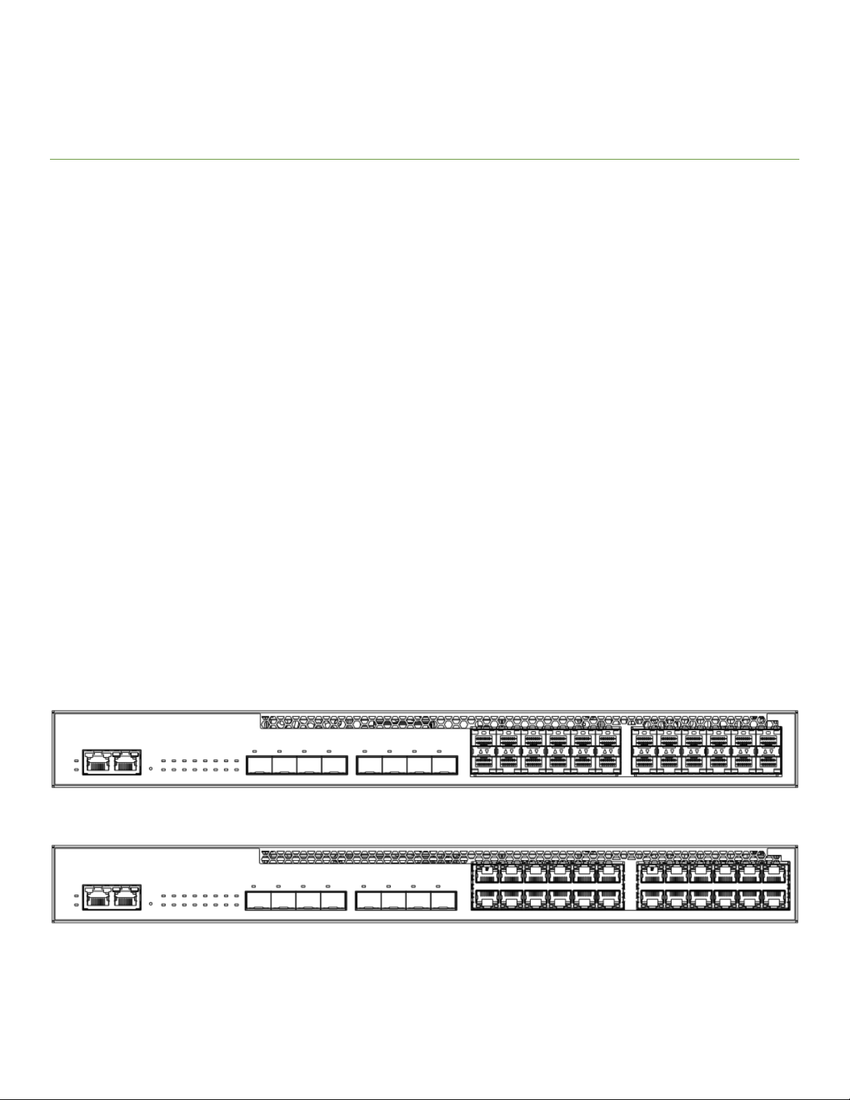
The following gures show the front and rear panels of the ICX 6610 models.
FIGURE 1 ICX 6610-24F front panel
FIGURE 2 ICX 6610-24 and ICX 6610-24P front panels
Brocade ICX 6610 Stackable Switch Hardware Installation Guide
53-1003620-03 13
Management interfaces
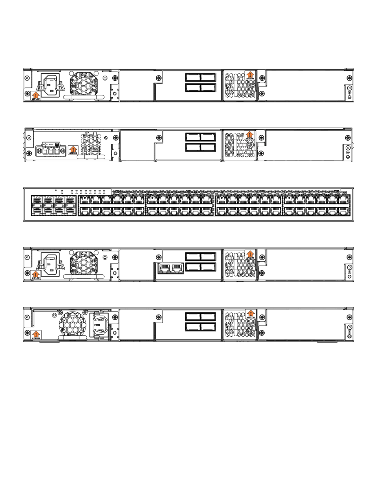
FIGURE 3 ICX 6610-24P rear panel
FIGURE 4 ICX 6610-48P rear panel with DC power supply
FIGURE 5 ICX 6610-48 and ICX 6610-48P front panels
FIGURE 6 ICX 6610-48P rear panel
FIGURE 7 ICX 6610-24, ICX 6610-24F, and ICX 6610-48, rear panels
Management interfaces
Each ICX 6610 includes the following management interfaces:
• Console management interface (RJ-45 serial port)
• Out-of-band management Interface (RJ-45 port)
• Reset button
These RJ-45 management ports are located together on the left side of the front panel on 24-port models, and in the middle of the rear
panel on 48P-port models.
14 53-1003620-03
Brocade ICX 6610 Stackable Switch Hardware Installation Guide
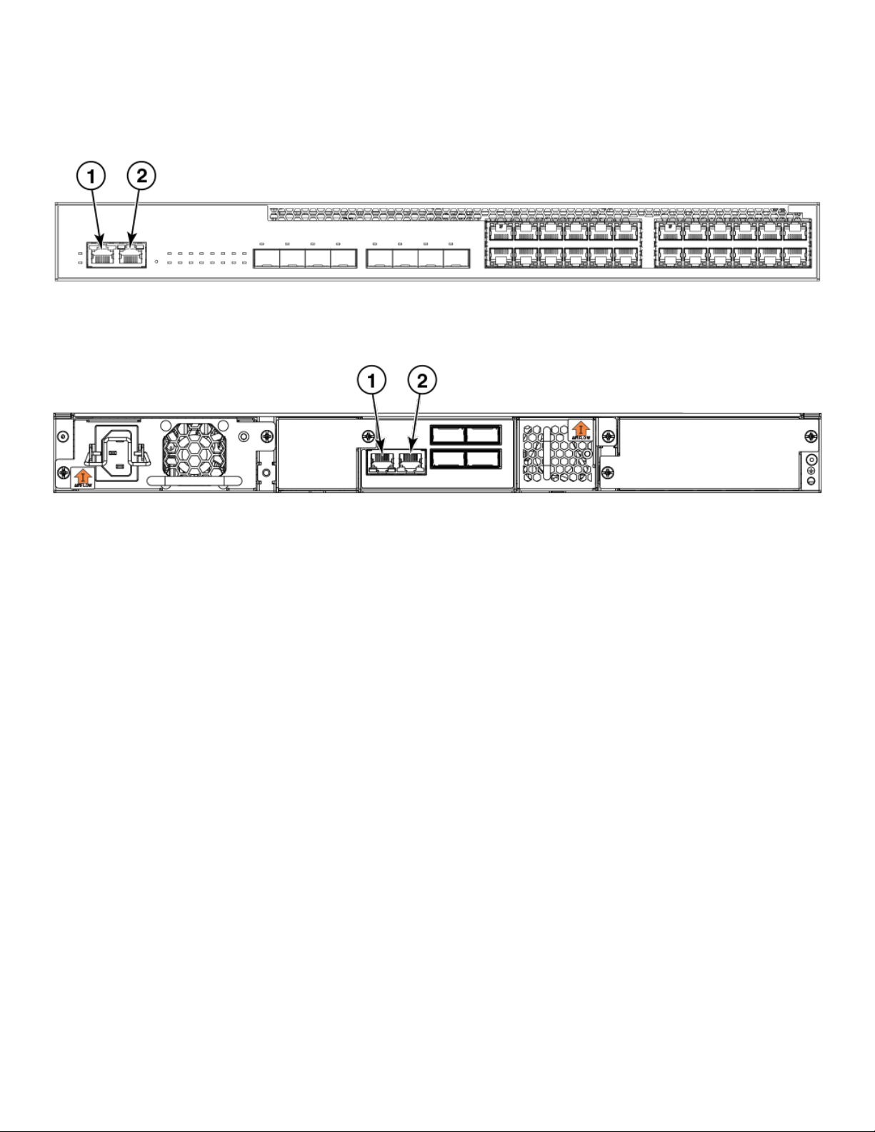
FIGURE 8 Management interfaces on 24-port models
1. Console port 2. Out-of-band management port
FIGURE 9 Management interfaces on 48-port models
Network interfaces for the ICX 6610
1. Out-of-band management port 2. Console port
Console management interface
The console management interface is an RJ-45 serial port that allows you to congure and manage the device using a third-party
terminal emulation application from a directly connected PC.
Out-of-band management interface
The out-of-band management interface is an RJ-45 port that allows you to
congure and manage the device from the network.
Reset button
The reset button allows you to restart the system without switching the power supplies o and on or using the CLI or Web Management
Interface. When the reset button is pressed, the system resets and the software is reloaded. The reset button is located next to the PSU
LED on both 24-port and 48-port models.
Network interfaces for the ICX 6610
ICX 6610-24, ICX 6610-24, ICX 6610-48, and ICX 6610-48P contain the following interfaces:
• 10/100/1000 Mbps ports with RJ-45 copper connectors
• SFP/SFP+ ports
• QSFP stacking ports
Brocade ICX 6610 Stackable Switch Hardware Installation Guide
53-1003620-03 15
Network interfaces for the ICX 6610
The ICX 6610-24F contains the following interfaces:
• 100/1000 SFP ber ports
• SFP/SFP+ ports
• QSFP stacking ports
Slot locations
There are three slot locations on the ICX 6610: slots 3 and 1 on the front panel and slot 2 on the rear panel.
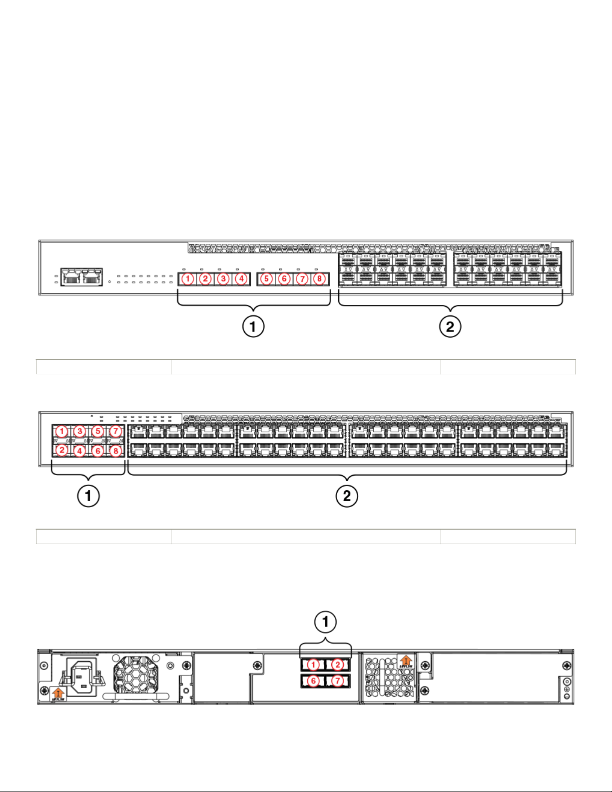
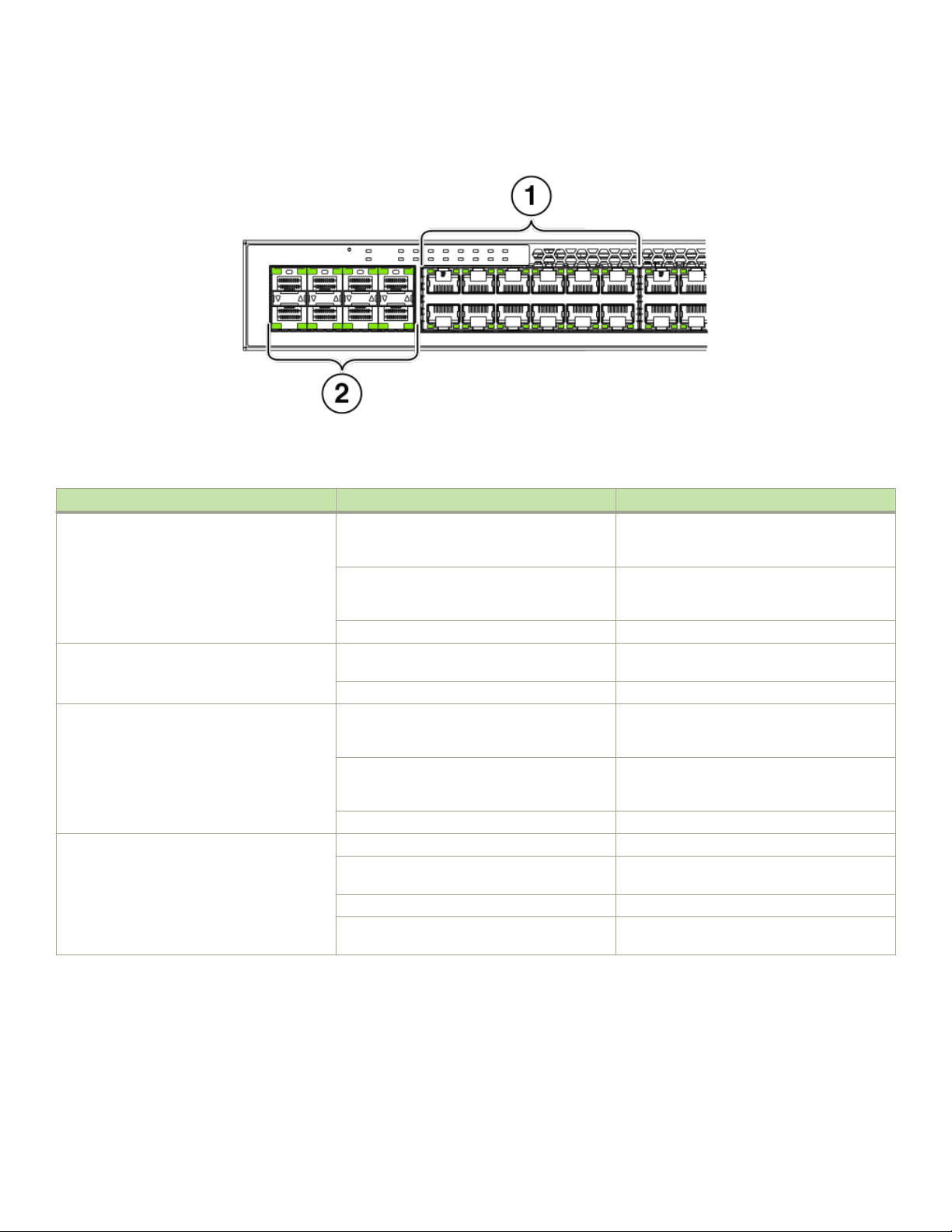
FIGURE 10 Slot locations on the front panel of the 24-port model of the ICX 6610
1 Slot 3, SFP/SFP+ ports 2 Slot 1, 10/100/1000 Mbps ports
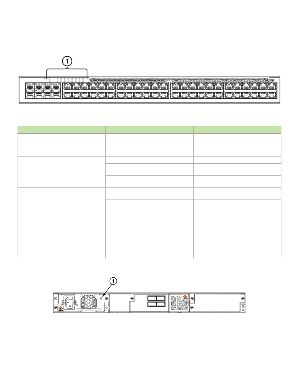
FIGURE 11 Slot locations on the front panel of the 48-port model of the ICX 6610
1 Slot 3, SFP/SFP+ ports 2 Slot 1, 10/100/1000 Mbps ports
The following gure shows slot 2 on the rear panel of the ICX 6610.
FIGURE 12 Slot location on the rear panel of the ICX 6610
16 53-1003620-03
Brocade ICX 6610 Stackable Switch Hardware Installation Guide

Network interfaces for the ICX 6610
1 Slot 2: Dedicated stacking ports 1, 2, 6, 7
Slot designations
The following table lists the slot designations for ICX 6610 models.
TABLE 2 Stack unit slots for ICX 6610 stackable devices
Device Slot 1 Slot 2 Slot 3
ICX 6610-24 10/100/1000 Mbps ports 1-24 QSFP stacking ports 1, 2, 6, 7 SFP/SFP+ ports 1-8
ICX 6610-24F 100/1000 Mbps ports 1-24 QSFP stacking ports 1, 2, 6, 7 SFP/SFP+ ports 1-8
ICX 6610-24P 10/100/1000 Mbps ports 1-24 QSFP stacking ports 1, 2, 6, 7 SFP/SFP+ ports 1-8
ICX 6610-48 10/100/1000 Mbps ports 1-48 QSFP stacking ports 1, 2, 6, 7 SFP/SFP+ ports 1-8
ICX 6610-48P 10/100/1000 Mbps ports 1-48 QSFP stacking ports 1, 2, 6, 7 SFP/SFP+ ports 1-8
10/100/1000 BASE-T ports
All ICX 6610 copper devices provide 24 or 48 RJ-45 ports that operate at 10 Mbps or 100 Mbps half or full duplex, or at 1000 Mbps
full duplex. In addition, ICX 6610 ber models provide 24 SFP ports.
Because all ports support automatic MDI or MDI-X operation, you can use straight-through cables for all network connections to PCs or
servers, or to other switches or hubs. In addition, it is ideal (and preferred) to use straight-through cables for switch-to-switch
connections.
Each port supports auto-negotiation, so the optimum transmission mode (half or full duplex), and the data rate (10, 100, or 1000 Mbps)
can be selected automatically. If a device connected to one of these ports does not support auto-negotiation, the communication mode
of the port can be congured manually.
SFP interfaces
The following table describes the SFP network interfaces supported on ICX 6610 devices.
TABLE 3 Supported network interfaces
Interface show media command description
1000Base-BX-D M-GBXD
1000Base-BX-U M-GBXU
1000Base-LHA M-LHA
1000Base-LHB M-LHB
1000Base-LX M-LX
1000Base-SX M-SX
1000Base-T C
1000Base-TX M-TX
100Base-FX M-FX
40-Gbps QSFP interface stacking ports
ICX 6610 devices have two 40-Gbps QSFP stacking ports and two 4 x 10-Gbps QSFP stacking ports on the rear panel. These ports
can perform data transmission directly through copper links of up to 5 meters.
Brocade ICX 6610 Stackable Switch Hardware Installation Guide
53-1003620-03 17

Specifying a port address
Specifying a port address
You can specify a port address for a data port, stacking port, or a management port.
Specifying a data port
The port address format is stack unit/slot/port, where:
• stack unit --Species the stack unit ID. Range is from 1 to 8. If the device is not part of a stack, the stack unit ID is 1.
• slot --Species the slot number. Can be 1 or 3.
• port --Species the port number in the slot. Range is from 1 to 24 (24-port models) or 1 to 48 (48-port models).
This example shows how to specify port 2 in slot 1 of a device that is not part of a stack:
Brocade (config) # interface ethernet 1/1/2
Specifying a stacking port
The port address format is stack unit/slot/port, where:
• stack unit
• slot
• port --Species the port number in the slot. Dedicated stacking ports are 1, 2, 6, and 7.
--Species the stack unit ID. Range is from 1 to 8.
--Species the slot number. Stacking ports are in slot 2.
This example shows how to specify stacking port 2 in slot 2 of unit 3 in a stack:
Brocade (config) # interface ethernet 3/2/2
Specifying a management port
The management port number is always 1. This example shows how to specify the management port:
Brocade (config) # interface management 1
The Up Link and Down Link LEDs on the front panel indicate operational status. If the Up Link or Down Link LED is on, the port is
connected. If the Up Link or Down Link LED is
o, no connection exists, or the link is down.
Port, system, and power status LEDs
The ICX 6610 includes LEDs that indicate the status of device components. This section identies and describes these LEDs.
18 53-1003620-03
Brocade ICX 6610 Stackable Switch Hardware Installation Guide
Port, system, and power status LEDs
FIGURE 13 Port status LEDs
1 and 2: Port status LEDs
TABLE 4 Port status LEDs
LED Condition Status
Ethernet (1-24/48) On/Flashing Green The port has established a valid link at 1000
Mbps. Flashing indicates the port is transmitting
and receiving user packets.
On/Flashing Yellow
O A link is not established with a remote port.
PoE (1-24/48) On The port is providing PoE power to a connected
O The port is not providing PoE power.
SFP/SFP+ (1F-8F) On/Flashing Green The SFP port is operating at 10 Gbps. Flashing
On/Flashing Yellow The SFP port is operating at 1 Gbps. Flashing
O A link is not established with a remote port.
Out-of-band management port (2 LEDs) O (both LEDs) Oine
On/Flashing (right side) Link-up. Flashing indicates the port is
Green (left side) 1000 Mbps Link-up
Left LED o, right LED on or ashing 10/100 Mbps Link-up. Flashing indicates the
The port has established a valid link at 10 or
100 Mbps. Flashing indicates the port is
transmitting and receiving user packets.
device.
indicates the port is transmitting and receiving
user packets.
indicates the port is transmitting and receiving
user packets.
transmitting and receiving user packets.
port is transmitting and receiving user packets.
Brocade ICX 6610 Stackable Switch Hardware Installation Guide
53-1003620-03 19
Port, system, and power status LEDs
FIGURE 14 System status LEDs
1. System status LEDs
TABLE 5 System status LEDs
LED Condition Status
PS1
PS2
(Power Supply Status)
Diag
(Diagnostic)
MS
(Stacking conguration)
XL1, XL2-XL5, XL6, XL7-XL10
(Stacking port status)
1-10+
(Stack ID)
Green Power supply is operating normally.
Yellow Power supply fault.
O Power o or failure.
Flashing Green System self-diagnostic test in progress.
Green System self-diagnostic test successfully
completed.
Yellow System self-diagnostic test has detected a fault.
(Blower, thermal or any interface fault.)
Green The device is the Active controller. Flashing
indicates the system is initializing.
Yellow Indicates the device is the Standby controller.
Flashing indicates the system is in Master
arbitration/selection state.
O Device is operating as a stack member, or is in
standalone mode.
Green Port is operating normally.
O Link has failed or there is no link.
Green Indicates the device stack ID.
FIGURE 15 Power status LED on 48-port models with AC power
1. Power status LED with AC power supply installed
20 53-1003620-03
Brocade ICX 6610 Stackable Switch Hardware Installation Guide
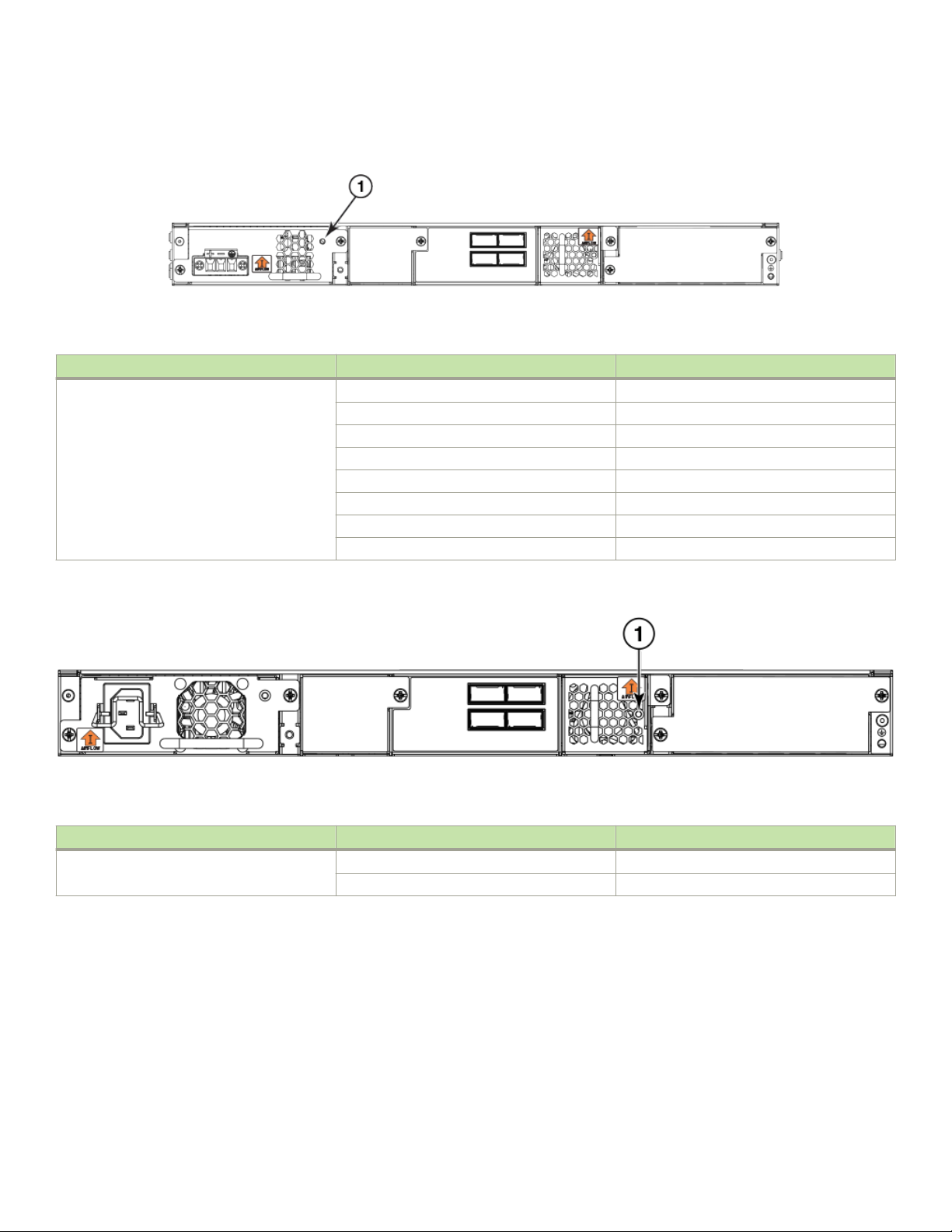
FIGURE 16 Power status LED on 48-port models with DC power
1. Power status LED with DC power supply installed
TABLE 6 Power status LED
LED Condition Status
Power status Green (steady) Nominal
O No input power
Flash 55 V out of range
Flash 12 V out of range
O Input power under voltage
Flash Fan fault
Flash OTP
Flash PSU disabled
Fan trays
FIGURE 17 Fan tray status LED on 48-port models
1. Fan tray LED
TABLE 7 Fan tray status LED
LED Condition Status
Fan Status Green Fan is operating normally
Yellow Fan failure
Fan trays
The device has two fan tray receptacles on the rear panel. Each device ships with one fan tray installed. A secondary fan tray can be
installed. Fan trays can be hot swapped. For instructions on installing and replacing a fan tray refer to Installing or replacing fan trays on
page 61 section.
Brocade ICX 6610 Stackable Switch Hardware Installation Guide
53-1003620-03 21
Power supplies
Power supplies
The device has two power supply receptacles on the rear panel. Each device ships with one AC power supply installed. Each power
supply has one standard power receptacle for the AC power cable. A secondary AC power supply can be installed to provide backup
power in case of a failure and for load-balancing when both power supplies are operational. AC power supplies can be hot swapped.
DC power supplies are available for the device. A secondary DC power supply can be installed for backup and load-balancing when both
power supplies are operational. DC power supplies can also be hot swapped.
NOTE
AC and DC power supplies cannot be installed and used in the same device. Mismatched power supplies in the same device
cause continual reboot on power up.
NOTE
Forward and reverse airow power supplies cannot be installed in the same
device.
For instructions on installing and replacing a power supply refer to Installing and replacing a power supply unit on page 55 section. For
information on LED status refer to Power status LEDs table in the section Port, system, and power status LEDs on page 18.
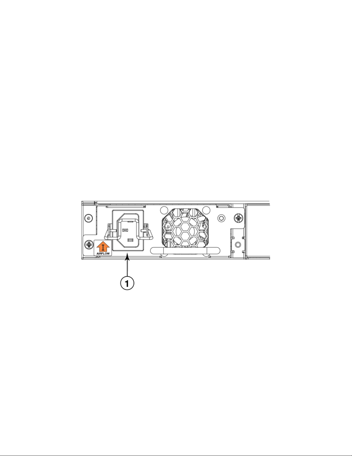
FIGURE 18 ICX 6610 AC power supply receptacle on 48-port models
1. AC power receptacle
22 53-1003620-03
Brocade ICX 6610 Stackable Switch Hardware Installation Guide
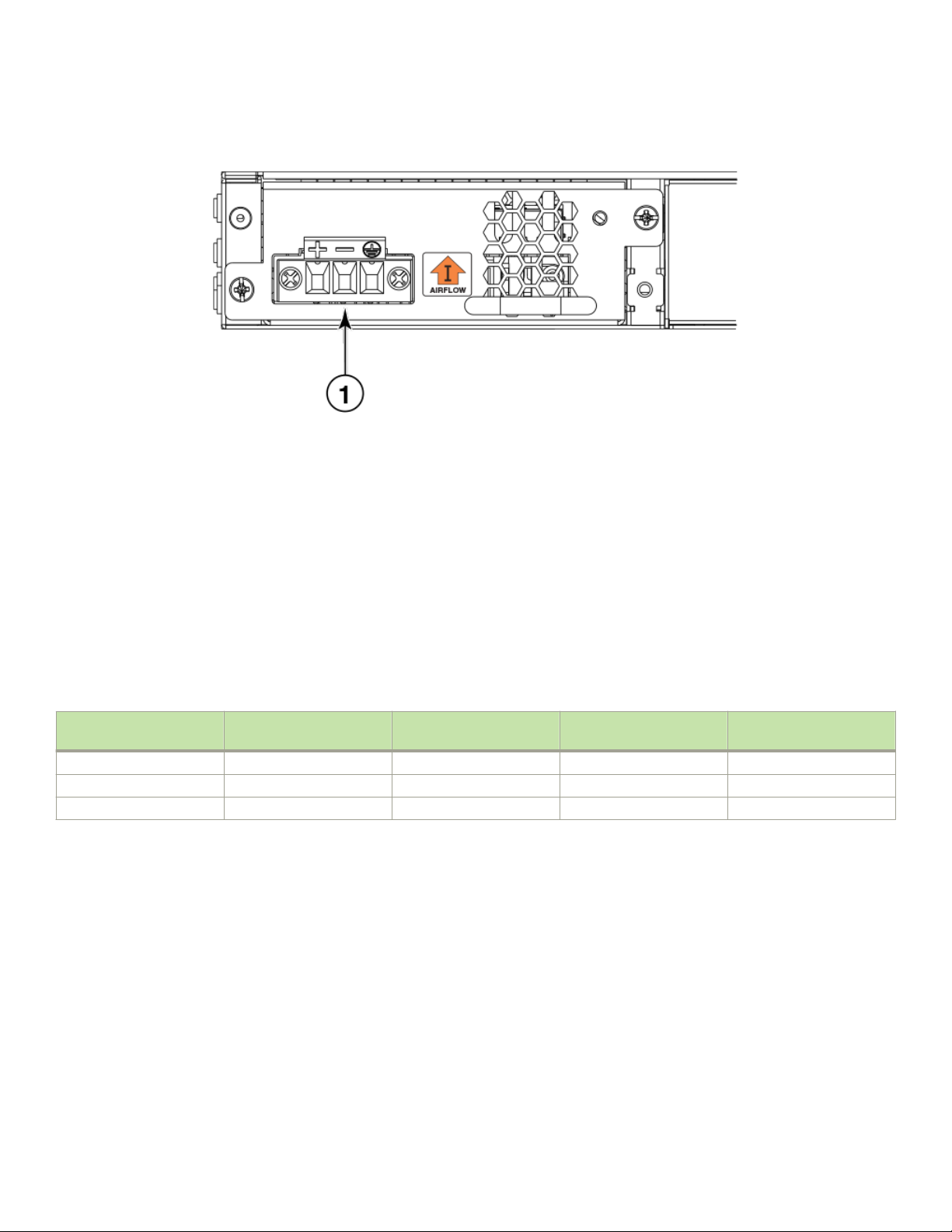
FIGURE 19 ICX 6610 DC power supply receptacle on 48-port models
1. DC power receptacle
PoE and PoE+ capacity on AC and DC power supplies
Power supplies
Several power options are available for the ICX 6610. All power supplies have the same overall form factor but
diering power inlets.
When a second power supply is installed in the same device for backup or increased capacity, it must be the same type.
Two AC power supplies are available, a 250 Watt unit and a 1000 Watt unit. The 1000 Watt AC power supply can be used for Power
over Ethernet (PoE) applications.
A 510 Watt DC power supply is also available and can be used to supply PoE where DC power is required.
The following table shows capacity per individual power supply and indicates the number of individual devices that can be powered by
each. A second matching power supply can be installed in the device to provide additional PoE power .
TABLE 8 AC and DC power supply capacity
PSU wattage System bus wattage PoE bus wattage Class 4 devices (30 W) per
PSU
AC System PSU 250 W 250 W N/A N/A
AC PoE PSU 1000 W 250 W 750 W 25
DC PoE PSU 510 W 250 W 258 W 8
Brocade ICX 6610 Stackable Switch Hardware Installation Guide
53-1003620-03 23

24 53-1003620-03
Brocade ICX 6610 Stackable Switch Hardware Installation Guide

Installing the ICX 6610 Switch
• Unpacking the device.......................................................................................................................................................................................25
• Installation tasks................................................................................................................................................................................................. 26
• Installation precautions....................................................................................................................................................................................26
• Preparing the installation site........................................................................................................................................................................28
• Installing the device...........................................................................................................................................................................................29
• Connecting devices in a traditional stack.................................................................................................................................................40
• Connecting devices in a mixed stack........................................................................................................................................................44
• Attaching a PC or terminal.............................................................................................................................................................................54
• Powering on the system................................................................................................................................................................................. 55
• Power supplies for the Brocade ICX 6610............................................................................................................................................ 55
• Installing or replacing fan trays.....................................................................................................................................................................61
DANGER
The procedures in this manual are for qualied service personnel.
DANGER
Before beginning the installation, see the precautions in “Power precautions.”
Unpacking the device
The ICX 6610 ships with all of the items in the following list. Verify the contents of your shipping container. If any items are missing,
contact the place of purchase.
Package contents
The following items are included in your shipping carton:
• ICX 6610 device
• AC power cable for North America (not included for models with DC power supply)
• Two 1-meter passive copper QSFP stacking cables (not included for models with DC power supply)
• Two mounting ears and screws
• 4 rubber feet
• Grounding terminal
General requirements
To manage the ICX 6610, you need a management station, such as a PC running a terminal emulation application. Connect the
management station to the console serial port on the switch.
Use the serial connection to perform basic
information is required to manage the system using the IronView Network Manager or using the CLI through Telnet or SSH.
conguration tasks, including assigning an IP address and network mask to the system. This
Brocade ICX 6610 Stackable Switch Hardware Installation Guide
53-1003620-03 25

Installation tasks
Installation tasks
Details for the following tasks are documented in the sections of this document noted in the “Where To Find More Information” column.
TABLE 9 Installation tasks
Task number Task Where to nd more information
1 Ensure that the physical environment that will
host the device has the proper cabling and
ventilation.
2 Install any required optional modules into the
device.
3 Install the device on a desktop, or in an
equipment rack.
4 Once the device is installed, plug the device into
a nearby power source that adheres to the
regulatory requirements outlined in this manual.
5 Attach a terminal or PC to the device. This will
enable you to congure the device through the
Command Line Interface (CLI).
6 No default password is assigned to the CLI. For
additional access security, assign a password.
7 Before attaching equipment to the device, you
need to congure an interface IP address to the
subnet on which the device will be located. Initial
IP address conguration is performed using the
CLI with a direct serial connection. Subsequent
IP address conguration can also be performed
using the CLI through Telnet or SSH.
8 Once you power on the device, assign IP
addresses to prepare the system for accepting
network equipment.
9 Test IP connectivity to other devices by pinging
them and tracing routes.
10 Continue conguring the device using the CLI
through Telnet or SSH. You also can use
IronView Network Manager to manage the
device.
11 Secure access to the device. See the FastIron Ethernet Switch Security
See the section Preparing the installation site on
page 28.
See the section Powering on the system on
page 55.
See the section Installing the device on page
29.
See the section Powering on the system on
page 55.
See the section Attaching a PC or terminal on
page 54.
See the section Assigning permanent passwords
on page 63.
See the section Conguring IP addresses on
page 64.
See the section Conguring IP addresses on
page 64.
See the section Testing connectivity on page
72.
See the FastIron Ethernet Switch Administration
Guide.
Conguration Guide.
Installation precautions
Follow all precautions when installing a device.
General precautions
DANGER
Laser Radiation. Do Not View Directly with Optical Instruments. Class 1M Laser Products.
26 53-1003620-03
Brocade ICX 6610 Stackable Switch Hardware Installation Guide
CAUTION
Do not install the device in an environment where the operating ambient temperature might exceed 45°C (113°F).
CAUTION
Make sure the airow around the front, sides, and back of the device is not
restricted.
CAUTION
Never leave tools inside the chassis.
DANGER
Risk of explosion if battery is replaced by an incorrect type. Dispose of used batteries according to the instructions.
Lifting precautions
DANGER
Make sure the rack housing the device is adequately secured to prevent it from becoming unstable or falling over.
DANGER
Mount the devices you install in a rack as low as possible. Place the heaviest device at the bottom and progressively place
lighter devices above.
Installation precautions
Power precautions
CAUTION
Use a separate branch circuit for each power cord, which provides redundancy in case one of the circuits fails.
DANGER
To avoid high voltage shock, do not open the device while the power is on.
CAUTION
Ensure that the device does not overload the power circuits, wiring, and over-current protection. To determine the possibility
of overloading the supply circuits, add the ampere (amp) ratings of all devices installed on the same circuit as the device.
Compare this total with the rating limit for the circuit. The maximum ampere ratings are usually printed on the devices near
the input power connectors.
DANGER
Remove both power cords before servicing.
DANGER
Disconnect the power cord from all power sources to completely remove power from the device.
CAUTION
Before plugging a cable into to any port, be sure to discharge the voltage stored on the cable by touching the electrical
contacts to ground surface.
Brocade ICX 6610 Stackable Switch Hardware Installation Guide
53-1003620-03 27

Preparing the installation site
DANGER
If the installation requires a dierent power cord than the one supplied with the device, make sure you use a power cord
displaying the mark of the safety agency that denes the regulations for power cords in your country. The mark is your
assurance that the power cord can be used safely with the device.
Preparing the installation site
Before installing the device, plan its location and orientation relative to other devices and equipment.
Cabling infrastructure
Make sure that the proper cabling is installed at the site. The following table lists the specications for the cables used with 10 Gbps, 1
Gbps, 100 Mbps, and 10 Mbps ports. For information about supported transceivers, refer to the tables in the Fiber-optic transceivers on
page 70.
NOTE
Cable installation and network conguration aect overall transmission capability. Industry guidelines on cable lengths and
range are provided in the following table. For network-specic recommendations, consult your local Brocade reseller or system
engineer.
TABLE 10 Cable length summary
Cable type Connector type Core diameter
(microns)
10GBase-ER SMF LC 9 µ n/a 40 km
10GBase-LR SMF LC 9 µ n/a 10 km
10GBase-LRM MMF LC 62.5 µ 200 MHz*km 220 m
MMF 50 µ 500 MHz*km 220 m
10GBase-SR MMF LC 50 µ 2000 MHz*km 300 m
10G SFP+ TWNX SFP+ n/a n/a 1, 3, and 5 m
1000Base-BXD SMF LC 9 µ n/a 10 km
1000Base-BXU SMF LC 9 µ n/a 10 km
1000Base-CWDM SMF LC 9 µ n/a 80 km
1000Base-LHA SMF LC 9 µ n/a 80 km
1000Base-LHB SMF LC 9 µ n/a 120 km
1000Base-LX MMF LC 62.5 µ 500 MHz*km 2 - 550 m
MMF 50 µ 400 MHz*km 2 - 550 m
MMF 50 µ 500 MHz*km 2 - 550 m
SMF 9 µ n/a 2 - 10000 m
1000Base-SX MMF LC 62.5 µ 200 MHz*km 0 .5 - 275 m
MMF 50 µ 400 MHz*km 0 .5 - 550 m
MMF 50 µ 500 MHz*km 0 .5 - 550 m
MMF 50 µ 1500 MHz*km 0 .5 - 550 m
MMF 50 µ 2000 MHz*km 0 .5 - 550 m
1000Base-T Copper RJ-45 n/a n/a 100 m
100Base-FX MMF LC 62.5 µ 500 MHz*km 2 km
Modal bandwidth
(MHz*km)
Range
28 53-1003620-03
Brocade ICX 6610 Stackable Switch Hardware Installation Guide

Installing the device
TABLE 10 Cable length summary (continued)
Cable type Connector type Core diameter
(microns)
100Base-FX-IR SMF LC 9 µ n/a 15 km
100Base-FX-LR SMF LC 9 µ n/a 40 km
40GBase Copper QSFP+ n/a n/a 1 and 5 m
40GBase-SR4 MMF MTP (MPO) 1×8 or
1×12 ribbon
connector
50 μ 2000 MHz*km
Modal bandwidth
(MHz*km)
4700 MHz*km
Range
100 m
150 m
Installation location
Devices can be mounted in a standard 19-inch equipment rack or on a at surface.
The site should meet the following requirements:
• Maintain the operating environment as specied in the section Environmental requirements on page 86.
• Operate at temperatures within 0° to 45° C (32° to 113° F) and humidity levels within 5% to 95%, non-condensing.
• Allow a minimum of 7.62 cm (3 in.) of space between the front and the back of the device and walls or other obstructions for
proper airow.
• Allow at least 7.62 cm (3 in.) of space at the front and back of the device for the twisted-pair, ber-optic, and power cabling.
• The site should be accessible for installing, cabling, and maintaining the devices.
• Allow the status LEDs to be clearly visible.
• Allow for twisted-pair cable to be routed away from power lines, uorescent lighting xtures, and other sources of electrical
interference, such as radios and transmitters.
• For a unit with AC power, allow for the unit to be connected to a separate grounded power outlet that provides 100 to 240
VAC, 50 to 60 Hz, is within 2 m (6.6 feet) of each device, and is powered from an independent circuit breaker. As with any
equipment, a lter or surge suppressor is recommended.
• For a unit with DC power, allow for the unit to be connected to a separate grounded power outlet that provides 40 to 72 VDC, is
within 2 m (6.6 feet) of each device, and is powered from an independent circuit breaker. As with any equipment, a lter or surge
suppressor is recommended.
• Some combinations of intake and exhaust airow may not be compatible with your environment. Consult your fan and power
supply module eld-replaceable unit (FRU) kit to determine the correct conguration.
• For a four-post rail mount conguration, order the appropriate mounting kit and refer to the kit documentation.
Installing the device
You can install the device on a desktop or in an equipment rack.
DANGER
Make sure the rack housing the device is adequately secured to prevent it from becoming unstable or falling over.
Desktop installation
Use the following steps to install the ICX 6610 on a desktop or other at surface.
Brocade ICX 6610 Stackable Switch Hardware Installation Guide
53-1003620-03 29
Installing the device
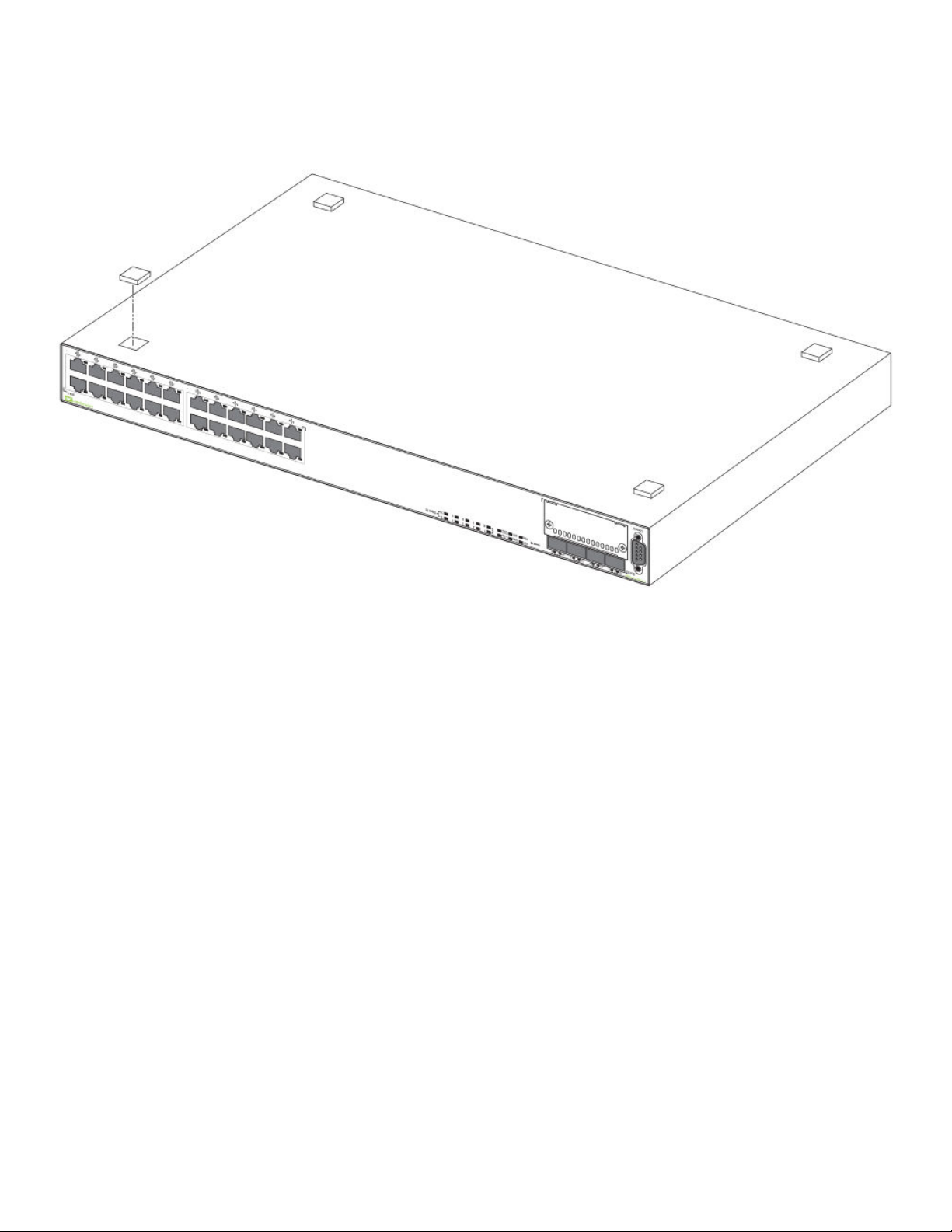
FIGURE 20 Attaching the adhesive feet
1. Attach the four adhesive feet to the bottom of the rst switch. If installing multiple switches, attach the adhesive feet to each one.
Place each device squarely on top of the one below.
2. Set the device on a at desktop, table, or shelf near an AC or a DC power source, whichever is appropriate for your installation.
Make sure that adequate ventilation is provided for the system. A 3 inch clearance is recommended on each side.
3. If installing a single switch only, refer to the section Powering on the system on page 55.
Rack mount installation
NOTE
You will need a Phillips screwdriver for installation.
Before mounting the switch in a rack, pay particular attention to the following factors:
• Temperature: Because the temperature within a rack assembly may be higher than the ambient room temperature, check that
the rack-environment temperature is within the specied operating temperature range.
• Mechanical loading: Do not place any equipment on top of a rack-mounted unit.
• Circuit overloading: Be sure that the supply circuit to the rack assembly is not overloaded.
• Grounding: Rack-mounted equipment should be properly grounded. Be sure to check supply connections in addition to direct
connections to the mains.
30 53-1003620-03
Brocade ICX 6610 Stackable Switch Hardware Installation Guide
 Loading...