


Brocade Communications Systems FESX624HF, FESX624HFE-PREM6, FESX624E-PREM6 Installation Manual

HARDWARE INSTALLATION GUIDE
Brocade FastIron Edge X-Series Hardware
Installation Guide
Part Number: 53-1002499-02
Publication Date: 15 June 2017

Copyright © 2017, Brocade Communications Systems, Inc. All Rights Reserved.
Brocade, Brocade Assurance, the B-wing symbol, ClearLink, DCX, Fabric OS, HyperEdge, ICX, MLX, MyBrocade, OpenScript, VCS, VDX, Vplane, and
Vyatta are registered trademarks, and Fabric Vision is a trademark of Brocade Communications Systems, Inc., in the United States and/or in other
countries. Other brands, products, or service names mentioned may be trademarks of others.
Notice: This document is for informational purposes only and does not set forth any warranty, expressed or implied, concerning any equipment, equipment
feature, or service offered or to be offered by Brocade. Brocade reserves the right to make changes to this document at any time, without notice, and
assumes no responsibility for its use. This informational document describes features that may not be currently available. Contact a Brocade sales office
for information on feature and product availability. Export of technical data contained in this document may require an export license from the United States
government.
The authors and Brocade Communications Systems, Inc. assume no liability or responsibility to any person or entity with respect to the accuracy of this
document or any loss, cost, liability, or damages arising from the information contained herein or the computer programs that accompany it.
The product described by this document may contain open source software covered by the GNU General Public License or other open source license
agreements. To find out which open source software is included in Brocade products, view the licensing terms applicable to the open source software, and
obtain a copy of the programming source code, please visit http://www.brocade.com/support/oscd.

Contents
Preface
Document conventions . . . . . . . . . . . . . . . . . . . . . . . . . . . . . . . . . . . . . . . . . . . . . . . . . . . . . . . . . . . . . . . . . . . . . . . . . . . . . . . . . . . . . . . . . . . . . . . . . .7
Text formatting. . . . . . . . . . . . . . . . . . . . . . . . . . . . . . . . . . . . . . . . . . . . . . . . . . . . . . . . . . . . . . . . . . . . . . . . . . . . . . . . . . . . . . . . . . . . . . . . . . . . . .7
Command syntax conventions. . . . . . . . . . . . . . . . . . . . . . . . . . . . . . . . . . . . . . . . . . . . . . . . . . . . . . . . . . . . . . . . . . . . . . . . . . . . . . . . . . . . . . . . 7
Notes, cautions, and danger notices . . . . . . . . . . . . . . . . . . . . . . . . . . . . . . . . . . . . . . . . . . . . . . . . . . . . . . . . . . . . . . . . . . . . . . . . . . . . . . . . . . .8
Brocade Resources . . . . . . . . . . . . . . . . . . . . . . . . . . . . . . . . . . . . . . . . . . . . . . . . . . . . . . . . . . . . . . . . . . . . . . . . . . . . . . . . . . . . . . . . . . . . . . . . . . . . .8
Contacting Brocade Technical Support . . . . . . . . . . . . . . . . . . . . . . . . . . . . . . . . . . . . . . . . . . . . . . . . . . . . . . . . . . . . . . . . . . . . . . . . . . . . . . . . . . . .9
Document feedback . . . . . . . . . . . . . . . . . . . . . . . . . . . . . . . . . . . . . . . . . . . . . . . . . . . . . . . . . . . . . . . . . . . . . . . . . . . . . . . . . . . . . . . . . . . . . . . . . . . . .9
About This Document
Document conventions . . . . . . . . . . . . . . . . . . . . . . . . . . . . . . . . . . . . . . . . . . . . . . . . . . . . . . . . . . . . . . . . . . . . . . . . . . . . . . . . . . . . . . . . . . . . . . . . 11
Product Overview
Product overview
Supported configurations
Software features
POE applications
IPv6 support
Hardware features
FESX624 and FESX624E-PREM6
FESX624HF and FESX624HFE-PREM6
FESX648 and FESX648E-PREM6
Control features
Network interfaces
Power supplies
Cooling system and fans
. . . . . . . . . . . . . . . . . . . . . . . . . . . . . . . . . . . . . . . . . . . . . . . . . . . . . . . . . . . . . . . . . . . . . . . . . . . . . . . . . . . . . . . . 13
. . . . . . . . . . . . . . . . . . . . . . . . . . . . . . . . . . . . . . . . . . . . . . . . . . . . . . . . . . . . . . . . . . . . . . . . . . . . . . 13
. . . . . . . . . . . . . . . . . . . . . . . . . . . . . . . . . . . . . . . . . . . . . . . . . . . . . . . . . . . . . . . . . . . . . . . . . . . . . . . . . . . . . . . . 14
. . . . . . . . . . . . . . . . . . . . . . . . . . . . . . . . . . . . . . . . . . . . . . . . . . . . . . . . . . . . . . . . . . . . . . . . . . . . . . . . . . . . . . . . 14
. . . . . . . . . . . . . . . . . . . . . . . . . . . . . . . . . . . . . . . . . . . . . . . . . . . . . . . . . . . . . . . . . . . . . . . . . . . . . . . . . . . . . . . . . . . 14
. . . . . . . . . . . . . . . . . . . . . . . . . . . . . . . . . . . . . . . . . . . . . . . . . . . . . . . . . . . . . . . . . . . . . . . . . . . . . . . . . . . . . . . 15
. . . . . . . . . . . . . . . . . . . . . . . . . . . . . . . . . . . . . . . . . . . . . . . . . . . . . . . . . . . . . . . . . . . . . 15
. . . . . . . . . . . . . . . . . . . . . . . . . . . . . . . . . . . . . . . . . . . . . . . . . . . . . . . . . . . . . . . .15
. . . . . . . . . . . . . . . . . . . . . . . . . . . . . . . . . . . . . . . . . . . . . . . . . . . . . . . . . . . . . . . . . . . . . 16
. . . . . . . . . . . . . . . . . . . . . . . . . . . . . . . . . . . . . . . . . . . . . . . . . . . . . . . . . . . . . . . . . . . . . . . . . . . . . . . . . . . . . 17
. . . . . . . . . . . . . . . . . . . . . . . . . . . . . . . . . . . . . . . . . . . . . . . . . . . . . . . . . . . . . . . . . . . . . . . . . . . . . . . . . . . 20
. . . . . . . . . . . . . . . . . . . . . . . . . . . . . . . . . . . . . . . . . . . . . . . . . . . . . . . . . . . . . . . . . . . . . . . . . . . . . . . . . . . . . . 21
. . . . . . . . . . . . . . . . . . . . . . . . . . . . . . . . . . . . . . . . . . . . . . . . . . . . . . . . . . . . . . . . . . . . . . . . . . . . . . 24
Installing a FastIron Compact Switch
Unpacking a system
Package contents
General requirements
Summary of installation tasks
Installation precautions
General precautions
Lifting precautions
Power precautions
Preparing the installation site
Cabling infrastructure
Installation location
Installing a redundant power supply
Installing an AC power supply
Installing a DC power supply
Installing the device
Desktop installation
Rack mount installation
Brocade FastIron Edge X-Series Hardware Installation Guide 3
Part Number: 53-1002499-02
. . . . . . . . . . . . . . . . . . . . . . . . . . . . . . . . . . . . . . . . . . . . . . . . . . . . . . . . . . . . . . . . . . . . . . . . . . . . . . . . . . . . . . 25
. . . . . . . . . . . . . . . . . . . . . . . . . . . . . . . . . . . . . . . . . . . . . . . . . . . . . . . . . . . . . . . . . . . . . . . . . . . . . . . . . . . . 25
. . . . . . . . . . . . . . . . . . . . . . . . . . . . . . . . . . . . . . . . . . . . . . . . . . . . . . . . . . . . . . . . . . . . . . . . . . . . . . . . . 25
. . . . . . . . . . . . . . . . . . . . . . . . . . . . . . . . . . . . . . . . . . . . . . . . . . . . . . . . . . . . . . . . . . . . . . . . . . . . . . 25
. . . . . . . . . . . . . . . . . . . . . . . . . . . . . . . . . . . . . . . . . . . . . . . . . . . . . . . . . . . . . . . . . . . . . . . . . . . . . . . . . . . . 26
. . . . . . . . . . . . . . . . . . . . . . . . . . . . . . . . . . . . . . . . . . . . . . . . . . . . . . . . . . . . . . . . . . . . . . . . . . . . . . . . . . 27
. . . . . . . . . . . . . . . . . . . . . . . . . . . . . . . . . . . . . . . . . . . . . . . . . . . . . . . . . . . . . . . . . . . . . . . . . . . . . . . . . . . 27
. . . . . . . . . . . . . . . . . . . . . . . . . . . . . . . . . . . . . . . . . . . . . . . . . . . . . . . . . . . . . . . . . . . . . . . . . . . . . . . . . . . 27
. . . . . . . . . . . . . . . . . . . . . . . . . . . . . . . . . . . . . . . . . . . . . . . . . . . . . . . . . . . . . . . . . . . . . . . . . . . . . . . 29
. . . . . . . . . . . . . . . . . . . . . . . . . . . . . . . . . . . . . . . . . . . . . . . . . . . . . . . . . . . . . . . . . . . . . . . . . . . . . . . . . 29
. . . . . . . . . . . . . . . . . . . . . . . . . . . . . . . . . . . . . . . . . . . . . . . . . . . . . . . . . . . . . . . . . . . . . . . . . . . . . . . . . . . 30
. . . . . . . . . . . . . . . . . . . . . . . . . . . . . . . . . . . . . . . . . . . . . . . . . . . . . . . . . . . . . . . . . . . . . . . . . . 30
. . . . . . . . . . . . . . . . . . . . . . . . . . . . . . . . . . . . . . . . . . . . . . . . . . . . . . . . . . . . . . . . . . . . . . . . . . . 30
. . . . . . . . . . . . . . . . . . . . . . . . . . . . . . . . . . . . . . . . . . . . . . . . . . . . . . . . . . . . . . . . . . . . . . . . . . . . 31
. . . . . . . . . . . . . . . . . . . . . . . . . . . . . . . . . . . . . . . . . . . . . . . . . . . . . . . . . . . . . . . . . . . . . . . . . . . . . . . . . . . . . . 32
. . . . . . . . . . . . . . . . . . . . . . . . . . . . . . . . . . . . . . . . . . . . . . . . . . . . . . . . . . . . . . . . . . . . . . . . . . . . . . . . . . . 32
. . . . . . . . . . . . . . . . . . . . . . . . . . . . . . . . . . . . . . . . . . . . . . . . . . . . . . . . . . . . . . . . . . . . . . . . . . . . . . . . 32

Powering on the system
Verifying proper operation
Observing the power status LEDs
Attaching a PC or terminal
Troubleshooting the serial connection
Connecting Network Devices and Checking Connectivity
Overview
Assigning permanent passwords
Configuring IP addresses
Connecting network devices
Testing connectivity
Troubleshooting network connections
. . . . . . . . . . . . . . . . . . . . . . . . . . . . . . . . . . . . . . . . . . . . . . . . . . . . . . . . . . . . . . . . . . . . . . . . . . . . . . . . . . . . . . . . . . . . . . 39
Recovering from a lost password
IPv4 devices
IPv6 devices
Connectors and cable specifications
Connecting to ethernet or fast ethernet hubs
Connecting to workstations, servers, or routers
Connecting a network device to a fiber port
Using a CX4 transceiver
Observing LEDs
Support for digital optical monitoring
. . . . . . . . . . . . . . . . . . . . . . . . . . . . . . . . . . . . . . . . . . . . . . . . . . . . . . . . . . . . . . . . . . . . . . . . . . . . . . . . . . 34
. . . . . . . . . . . . . . . . . . . . . . . . . . . . . . . . . . . . . . . . . . . . . . . . . . . . . . . . . . . . . . . . . . . . . . . . . . . . . . . . . 35
. . . . . . . . . . . . . . . . . . . . . . . . . . . . . . . . . . . . . . . . . . . . . . . . . . . . . . . . . . . . . . . . . . . . . . . 35
. . . . . . . . . . . . . . . . . . . . . . . . . . . . . . . . . . . . . . . . . . . . . . . . . . . . . . . . . . . . . . . . . . . . . . . . . . . . . . . . . 36
. . . . . . . . . . . . . . . . . . . . . . . . . . . . . . . . . . . . . . . . . . . . . . . . . . . . . . . . . . . . . . . . . . . . 37
. . . . . . . . . . . . . . . . . . . . . . . . . . . . . . . . . . . . . . . . . . . . . . . . . . . . . . . . . . . . . . . . . . . . . . . . . . . . 39
. . . . . . . . . . . . . . . . . . . . . . . . . . . . . . . . . . . . . . . . . . . . . . . . . . . . . . . . . . . . . . . . . . . . . . . . 40
. . . . . . . . . . . . . . . . . . . . . . . . . . . . . . . . . . . . . . . . . . . . . . . . . . . . . . . . . . . . . . . . . . . . . . . . . . . . . . . . . . 41
. . . . . . . . . . . . . . . . . . . . . . . . . . . . . . . . . . . . . . . . . . . . . . . . . . . . . . . . . . . . . . . . . . . . . . . . . . . . . . . . . . . . . . . . 41
. . . . . . . . . . . . . . . . . . . . . . . . . . . . . . . . . . . . . . . . . . . . . . . . . . . . . . . . . . . . . . . . . . . . . . . . . . . . . . . . . . . . . . . . 43
. . . . . . . . . . . . . . . . . . . . . . . . . . . . . . . . . . . . . . . . . . . . . . . . . . . . . . . . . . . . . . . . . . . . . . . . . . . . . . . 45
. . . . . . . . . . . . . . . . . . . . . . . . . . . . . . . . . . . . . . . . . . . . . . . . . . . . . . . . . . . . . . . . . . . . . . 45
. . . . . . . . . . . . . . . . . . . . . . . . . . . . . . . . . . . . . . . . . . . . . . . . . . . . . . . . . . . . . . . 45
. . . . . . . . . . . . . . . . . . . . . . . . . . . . . . . . . . . . . . . . . . . . . . . . . . . . . . . . . . . . . 47
. . . . . . . . . . . . . . . . . . . . . . . . . . . . . . . . . . . . . . . . . . . . . . . . . . . . . . . . . . . . . . . . 47
. . . . . . . . . . . . . . . . . . . . . . . . . . . . . . . . . . . . . . . . . . . . . . . . . . . . . . . . . . . . . . . . . . . . . . . . . . . . . . . 48
. . . . . . . . . . . . . . . . . . . . . . . . . . . . . . . . . . . . . . . . . . . . . . . . . . . . . . . . . . . . . . . . . . . . . . . . . . . . . . . . . . . . . . 49
. . . . . . . . . . . . . . . . . . . . . . . . . . . . . . . . . . . . . . . . . . . . . . . . . . . . . . . . . . . . . . . . . . . . . . . . . . . . . . . . . . . . . 49
. . . . . . . . . . . . . . . . . . . . . . . . . . . . . . . . . . . . . . . . . . . . . . . . . . . . . . . . . . . . . . . . . . . . . . . . 50
. . . . . . . . . . . . . . . . . . . . . . . . . . . . . . . . . . . . . . . . . . . . . . . . . . . . . . . . . . . . . . . . . . . . . 51
Managing the FastIron Compact Switch
Overview
Viewing the device type
Managing temperature settings and fan speed on FastIron X Series compact switches
Displaying management module CPU usage. . . . . . . . . . . . . . . . . . . . . . . . . . . . . . . . . . . . . . . . . . . . . . . . . . . . . . . . . . . . . . . . . . . . . . . . . . . . . 58
Removing MAC address entries
Replacing and Maintaining the Hardware
Hardware maintenance
Replacing a power supply
. . . . . . . . . . . . . . . . . . . . . . . . . . . . . . . . . . . . . . . . . . . . . . . . . . . . . . . . . . . . . . . . . . . . . . . . . . . . . . . . . . . . . . . . . . . . . . 53
. . . . . . . . . . . . . . . . . . . . . . . . . . . . . . . . . . . . . . . . . . . . . . . . . . . . . . . . . . . . . . . . . . . . . . . . . . . . . . . . . . . 53
. . . . . . . . . . . . . . . . . . . . . . . . . . . . . . . . . . 53
Temperature sensors
Fan speed
Temperature thresholds
Changing the temperature warning level
Changing the shutdown temperature
Changing the device polling interval
Displaying the temperature on a FastIron X Series 24-port switch
Displaying the temperature and temperature thresholds on a FastIron X Series 48-port switch
Displaying the fan speed on a FastIron X Series 48-port switch
. . . . . . . . . . . . . . . . . . . . . . . . . . . . . . . . . . . . . . . . . . . . . . . . . . . . . . . . . . . . . . . . . . . . . . . . . . . . . . . . . . . . . . . . . . 54
. . . . . . . . . . . . . . . . . . . . . . . . . . . . . . . . . . . . . . . . . . . . . . . . . . . . . . . . . . . . . . . . . . . . . . . . . . . . . . . . . 53
. . . . . . . . . . . . . . . . . . . . . . . . . . . . . . . . . . . . . . . . . . . . . . . . . . . . . . . . . . . . . . . . . . . . . . . . . . . . . . . 54
. . . . . . . . . . . . . . . . . . . . . . . . . . . . . . . . . . . . . . . . . . . . . . . . . . . . . . . . . . . . . . . . . . . 55
. . . . . . . . . . . . . . . . . . . . . . . . . . . . . . . . . . . . . . . . . . . . . . . . . . . . . . . . . . . . . . . . . . . . . 55
. . . . . . . . . . . . . . . . . . . . . . . . . . . . . . . . . . . . . . . . . . . . . . . . . . . . . . . . . . . . . . . . . . . . . . 56
. . . . . . . . . . . . . . . . . . . . . . . . . . . . . . . . . . . . . . . . . . . . . . 56
. . . . . . . . . . . . . . . . . . . . . . . . 57
. . . . . . . . . . . . . . . . . . . . . . . . . . . . . . . . . . . . . . . . . . . . . . . . 57
. . . . . . . . . . . . . . . . . . . . . . . . . . . . . . . . . . . . . . . . . . . . . . . . . . . . . . . . . . . . . . . . . . . . . . . . . . . . 58
. . . . . . . . . . . . . . . . . . . . . . . . . . . . . . . . . . . . . . . . . . . . . . . . . . . . . . . . . . . . . . . . . . . . . . . . . . . . . . . . . . . 61
. . . . . . . . . . . . . . . . . . . . . . . . . . . . . . . . . . . . . . . . . . . . . . . . . . . . . . . . . . . . . . . . . . . . . . . . . . . . . . . . . 61
Installation precautions and warnings
Determining which power supply failed
AC power supplies
DC power supplies
Verifying proper operation
Displaying the status of the power supplies
. . . . . . . . . . . . . . . . . . . . . . . . . . . . . . . . . . . . . . . . . . . . . . . . . . . . . . . . . . . . . . . . . . . . . . . . . . . . . . . . . . . 62
. . . . . . . . . . . . . . . . . . . . . . . . . . . . . . . . . . . . . . . . . . . . . . . . . . . . . . . . . . . . . . . . . . . . . . . . . . . . . . . . . . . 63
. . . . . . . . . . . . . . . . . . . . . . . . . . . . . . . . . . . . . . . . . . . . . . . . . . . . . . . . . . . . . . . . . . . . . . . . . . . . . 65
. . . . . . . . . . . . . . . . . . . . . . . . . . . . . . . . . . . . . . . . . . . . . . . . . . . . . . . . . . . . . . . . . . . . . 62
. . . . . . . . . . . . . . . . . . . . . . . . . . . . . . . . . . . . . . . . . . . . . . . . . . . . . . . . . . . . . . . . . . . 62
. . . . . . . . . . . . . . . . . . . . . . . . . . . . . . . . . . . . . . . . . . . . . . . . . . . . . . . . . . . . . . . .65
4 Brocade FastIron Edge X-Series Hardware Installation Guide
Part Number: 53-1002499-02

Installing or replacing a 10-Gigabit Ethernet module
Disassembling the Device
Removing a 10-Gigabit Ethernet module
Installing a 10-Gigabit Ethernet module
Re-assembling the device
Replacing a CPU DIMM
Replacing a fiber optic module
Removing a fiber optic module
Installing a new fiber optic module
Cabling a fiber optic module
Cleaning the fiber optic connectors
Upgrading the device to run layer 3 software
Hardware Specifications
Device specifications
Physical dimensions
Environmental Considerations
British Thermal Units (BTUs)
Cooling
Regulatory compliance
Power source interruptions
Pinouts and signaling
Cable specifications
Power cords
Power supply specifications
Physical dimensions and weight
Environmental considerations
Electrical specifications
Input connector and plug
Regulatory compliance
Safety warnings
. . . . . . . . . . . . . . . . . . . . . . . . . . . . . . . . . . . . . . . . . . . . . . . . . . . . . . . . . . . . . . . . . . . . . . . . . . . . . . . . . . . . . . . . . . . . 74
. . . . . . . . . . . . . . . . . . . . . . . . . . . . . . . . . . . . . . . . . . . . . . . . . . . . . . . . . . . . . . . . . . . . . . . . . . . . . . . . . . . . . . . . 78
. . . . . . . . . . . . . . . . . . . . . . . . . . . . . . . . . . . . . . . . . . . . . . . . . . . . . . . . . . . . . . . . . . . . . . . . . . . . . . . . . . . . . 83
. . . . . . . . . . . . . . . . . . . . . . . . . . . . . . . . . . . . . . . . . . . . . . . . . . . . . . . . . . . . . . . . . . . . . . . . . . . . . 66
. . . . . . . . . . . . . . . . . . . . . . . . . . . . . . . . . . . . . . . . . . . . . . . . . . . . . . . . . . . . . . . . . . . . . . . . . . . . . 68
. . . . . . . . . . . . . . . . . . . . . . . . . . . . . . . . . . . . . . . . . . . . . . . . . . . . . . . . . . . . . . . . . . . . . . . . . . . . . . . . . . . 68
. . . . . . . . . . . . . . . . . . . . . . . . . . . . . . . . . . . . . . . . . . . . . . . . . . . . . . . . . . . . . . . . . . . . . . . . . . . . . . 68
. . . . . . . . . . . . . . . . . . . . . . . . . . . . . . . . . . . . . . . . . . . . . . . . . . . . . . . . . . . . . . . . . . . . . . . . . . 69
. . . . . . . . . . . . . . . . . . . . . . . . . . . . . . . . . . . . . . . . . . . . . . . . . . . . . . . . . . . . . . . . . . . . . . . 70
. . . . . . . . . . . . . . . . . . . . . . . . . . . . . . . . . . . . . . . . . . . . . . . . . . . . . . . . . . . . . . . . . . . . . . . . . . . . 70
. . . . . . . . . . . . . . . . . . . . . . . . . . . . . . . . . . . . . . . . . . . . . . . . . . . . . . . . . . . . . . . . . . . . . . . . . . 70
. . . . . . . . . . . . . . . . . . . . . . . . . . . . . . . . . . . . . . . . . . . . . . . . . . . . . . . . . . . . . . . . . . . . . . . . . . . . . . . . . 73
. . . . . . . . . . . . . . . . . . . . . . . . . . . . . . . . . . . . . . . . . . . . . . . . . . . . . . . . . . . . . . . . . . . . . . . . . . . . . . . . . . 73
. . . . . . . . . . . . . . . . . . . . . . . . . . . . . . . . . . . . . . . . . . . . . . . . . . . . . . . . . . . . . . . . . . . . . . . . . . 73
. . . . . . . . . . . . . . . . . . . . . . . . . . . . . . . . . . . . . . . . . . . . . . . . . . . . . . . . . . . . . . . . . . . . . . . . . . . 74
. . . . . . . . . . . . . . . . . . . . . . . . . . . . . . . . . . . . . . . . . . . . . . . . . . . . . . . . . . . . . . . . . . . . . . . . . . . . . . . . 74
. . . . . . . . . . . . . . . . . . . . . . . . . . . . . . . . . . . . . . . . . . . . . . . . . . . . . . . . . . . . . . . . . . . . . . . . . . . . . 74
. . . . . . . . . . . . . . . . . . . . . . . . . . . . . . . . . . . . . . . . . . . . . . . . . . . . . . . . . . . . . . . . . . . . . . . . . . . . . . . . . 75
. . . . . . . . . . . . . . . . . . . . . . . . . . . . . . . . . . . . . . . . . . . . . . . . . . . . . . . . . . . . . . . . . . . . . . . . . . . . . . . . . . 76
. . . . . . . . . . . . . . . . . . . . . . . . . . . . . . . . . . . . . . . . . . . . . . . . . . . . . . . . . . . . . . . . . . . . . . . . . . . . . . . . 79
. . . . . . . . . . . . . . . . . . . . . . . . . . . . . . . . . . . . . . . . . . . . . . . . . . . . . . . . . . . . . . . . . . . . . . . . . 79
. . . . . . . . . . . . . . . . . . . . . . . . . . . . . . . . . . . . . . . . . . . . . . . . . . . . . . . . . . . . . . . . . . . . . . . . . . . 80
. . . . . . . . . . . . . . . . . . . . . . . . . . . . . . . . . . . . . . . . . . . . . . . . . . . . . . . . . . . . . . . . . . . . . . . . . . . . . . . . 80
. . . . . . . . . . . . . . . . . . . . . . . . . . . . . . . . . . . . . . . . . . . . . . . . . . . . . . . . . . . . . . . . . . . . . . . . . . . . . . 81
. . . . . . . . . . . . . . . . . . . . . . . . . . . . . . . . . . . . . . . . . . . . . . . . . . . . . . . . . . . . . . . . . . . . . . . . . . . . . . . . 82
. . . . . . . . . . . . . . . . . . . . . . . . . . . . . . . . . . . . . . . . . . . . . . . . . . . . . . . . . . . . 66
. . . . . . . . . . . . . . . . . . . . . . . . . . . . . . . . . . . . . . . . . . . . . . . . . . . . . . . . . . . . . . . . . 67
. . . . . . . . . . . . . . . . . . . . . . . . . . . . . . . . . . . . . . . . . . . . . . . . . . . . . . . . . . . . . . . . . . . 67
. . . . . . . . . . . . . . . . . . . . . . . . . . . . . . . . . . . . . . . . . . . . . . . . . . . . . . . . . . . . . . . . . . 71
Layer 3 Upgrade Procedures for FastIron IPv4 devices
Overview
Upgrade kit contents
Installation overview
Detailed procedures
Regulatory Statements
U.S.A.
Industry Canada statement
Europe and Australia
Japan VCCI statement
Japan Denan power cord statement
Korea
Russia
Brocade FastIron Edge X-Series Hardware Installation Guide 5
Part Number: 53-1002499-02
. . . . . . . . . . . . . . . . . . . . . . . . . . . . . . . . . . . . . . . . . . . . . . . . . . . . . . . . . . . . . . . . . . . . . . . . . . . . . . . . . . . . . . . . . . . . . . 85
. . . . . . . . . . . . . . . . . . . . . . . . . . . . . . . . . . . . . . . . . . . . . . . . . . . . . . . . . . . . . . . . . . . . . . . . . . . . . . . . . . . . . 85
. . . . . . . . . . . . . . . . . . . . . . . . . . . . . . . . . . . . . . . . . . . . . . . . . . . . . . . . . . . . . . . . . . . . . . . . . . . . . . . . . . . . . . 86
. . . . . . . . . . . . . . . . . . . . . . . . . . . . . . . . . . . . . . . . . . . . . . . . . . . . . . . . . . . . . . . . . . . . . . . . . . . . . . . . . . . . . . 87
Hardware installation
Software installation
. . . . . . . . . . . . . . . . . . . . . . . . . . . . . . . . . . . . . . . . . . . . . . . . . . . . . . . . . . . . . . . . . . . . . . . . . . . . . . . . . . 87
. . . . . . . . . . . . . . . . . . . . . . . . . . . . . . . . . . . . . . . . . . . . . . . . . . . . . . . . . . . . . . . . . . . . . . . . . . . . . . . . . . 89
. . . . . . . . . . . . . . . . . . . . . . . . . . . . . . . . . . . . . . . . . . . . . . . . . . . . . . . . . . . . . . . . . . . . . . . . . . . . . . . . . . . . . . . . . . . . . . . . . 91
. . . . . . . . . . . . . . . . . . . . . . . . . . . . . . . . . . . . . . . . . . . . . . . . . . . . . . . . . . . . . . . . . . . . . . . . . . . . . . . . 91
. . . . . . . . . . . . . . . . . . . . . . . . . . . . . . . . . . . . . . . . . . . . . . . . . . . . . . . . . . . . . . . . . . . . . . . . . . . . . . . . . . . . . 91
. . . . . . . . . . . . . . . . . . . . . . . . . . . . . . . . . . . . . . . . . . . . . . . . . . . . . . . . . . . . . . . . . . . . . . . . . . . . . . . . . . . . 91
. . . . . . . . . . . . . . . . . . . . . . . . . . . . . . . . . . . . . . . . . . . . . . . . . . . . . . . . . . . . . . . . . . . . . . . . . 92
. . . . . . . . . . . . . . . . . . . . . . . . . . . . . . . . . . . . . . . . . . . . . . . . . . . . . . . . . . . . . . . . . . . . . . . . . . . . . . . . . . . . . . . . . . . . . . . . . 92
. . . . . . . . . . . . . . . . . . . . . . . . . . . . . . . . . . . . . . . . . . . . . . . . . . . . . . . . . . . . . . . . . . . . . . . . . . . . . . . . . . . . . . . . . . . . . . . . 92

Caution and Danger Notices
Caution
Danger
. . . . . . . . . . . . . . . . . . . . . . . . . . . . . . . . . . . . . . . . . . . . . . . . . . . . . . . . . . . . . . . . . . . . . . . . . . . . . . . . . . . . . . . . . . . . . . . . 93
. . . . . . . . . . . . . . . . . . . . . . . . . . . . . . . . . . . . . . . . . . . . . . . . . . . . . . . . . . . . . . . . . . . . . . . . . . . . . . . . . . . . . . . . . . . . . . . . 98
6 Brocade FastIron Edge X-Series Hardware Installation Guide
Part Number: 53-1002499-02

Preface
•
Document conventions . . . . . . . . . . . . . . . . . . . . . . . . . . . . . . . . . . . . . . . . . . . . . . . . . . . . . . . . . . . . . . . . . . . . . . . . . . . . . . . . 7
•
Brocade resources . . . . . . . . . . . . . . . . . . . . . . . . . . . . . . . . . . . . . . . . . . . . . . . . . . . . . . . . . . . . . . . . . . . . . . . . . . . . . . . . . . . . 8
•
Contacting Brocade Technical Support . . . . . . . . . . . . . . . . . . . . . . . . . . . . . . . . . . . . . . . . . . . . . . . . . . . . . . . . . . . . . . . . . . 9
•
Document feedback. . . . . . . . . . . . . . . . . . . . . . . . . . . . . . . . . . . . . . . . . . . . . . . . . . . . . . . . . . . . . . . . . . . . . . . . . . . . . . . . . . . 9
Document conventions
The document conventions describe text formatting conventions, command syntax conventions, and important notice formats used in
Brocade technical documentation.
Text formatting conventions
Text formatting conventions such as boldface, italic, or Courier font may be used in the flow of the text to highlight specific words or
phrases.
Format Description
bold text Identifies command names
Identifies keywords and operands
Identifies the names of user-manipulated GUI elements
Identifies text to enter at the GUI
italic text Identifies emphasis
Identifies variables
Identifies document titles
Courier font
Identifies CLI output
Identifies command syntax examples
Command syntax conventions
Bold and italic text identify command syntax components. Delimiters and operators define groupings of parameters and their logical
relationships.
Convention Description
bold text Identifies command names, keywords, and command options.
italic text Identifies a variable.
value In Fibre Channel products, a fixed value provided as input to a command option is
printed in plain text, for example, --show WWN.
[ ] Syntax components displayed within square brackets are optional.
Default responses to system prompts are enclosed in square brackets.
Brocade FastIron Edge X-Series Hardware Installation Guide 7
Part Number: 53-1002499-02

NOTE
ATTENTION
CAUTION
DANGER
Preface
Brocade resources
{ x | y | z } A choice of required parameters is enclosed in curly brackets separated by
vertical bars. You must select one of the options.
In Fibre Channel products, square brackets may be used instead for this purpose.
x | y A vertical bar separates mutually exclusive elements.
< > Nonprinting characters, for example, passwords, are enclosed in angle brackets.
... Repeat the previous element, for example, member[member...].
\ Indicates a “soft” line break in command examples. If a backslash separates two
lines of a command input, enter the entire command at the prompt without the
backslash.
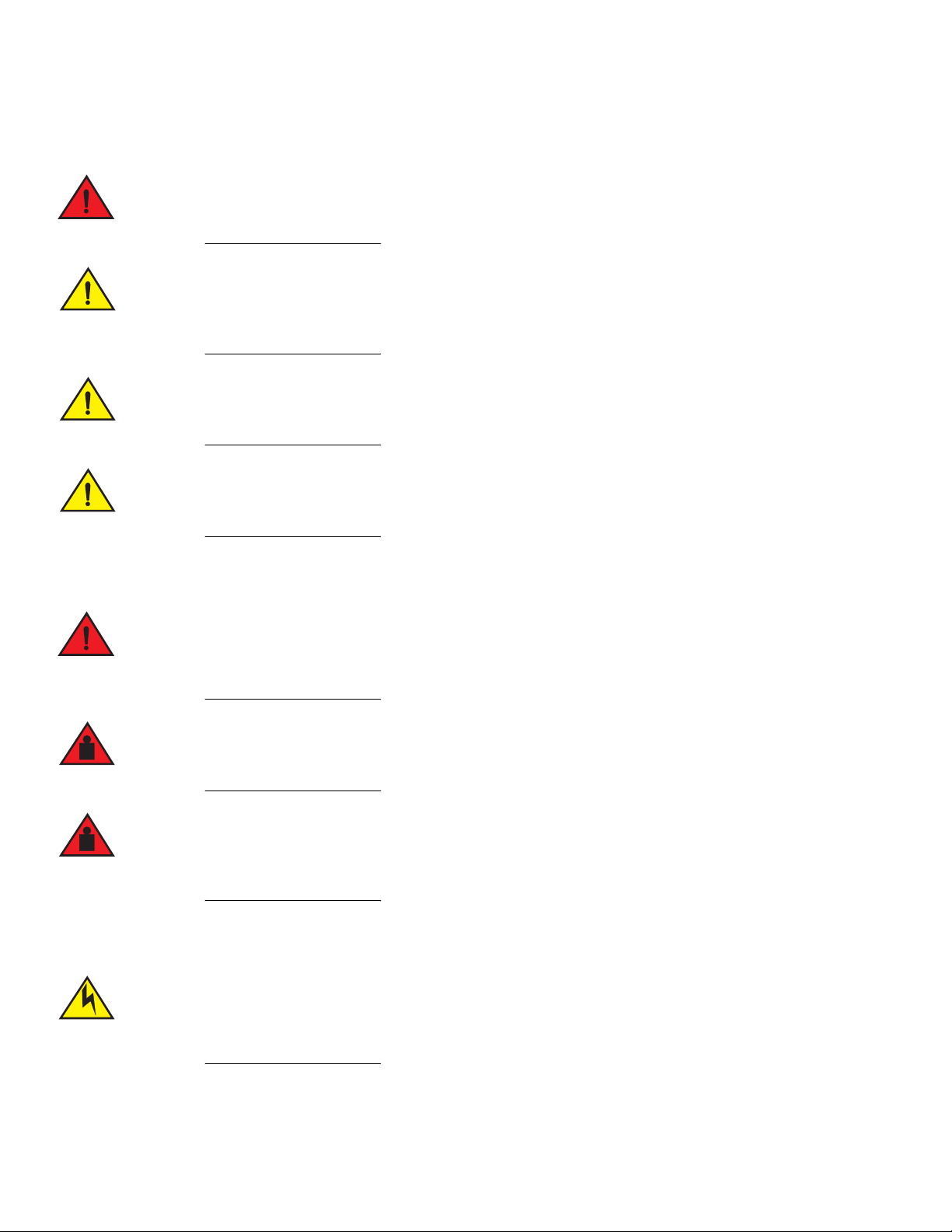
Notes, cautions, and warnings
Notes, cautions, and warning statements may be used in this document. They are listed in the order of increasing severity of potential
hazards.
A Note provides a tip, guidance, or advice, emphasizes important information, or provides a reference to related information.
An Attention statement indicates a stronger note, for example, to alert you when traffic might be interrupted or the device might
reboot.
A Caution statement alerts you to situations that can be potentially hazardous to you or cause damage to hardware, firmware, software, or data.
A Danger statement indicates conditions or situations that can be potentially lethal or extremely hazardous to you. Safety labels are also attached directly to products to warn of these conditions or situations.
Brocade resources
Visit the Brocade website to locate related documentation for your product and additional Brocade resources.
You can download additional publications supporting your product at www.brocade.com. Select the Brocade Products tab to locate your
product, then click the Brocade product name or image to open the individual product page. The user manuals are available in the
resources module at the bottom of the page under the Documentation category.
To get up-to-the-minute information on Brocade products and resources, go to MyBrocade. You can register at no cost to obtain a user
ID and password.
Release notes are available on MyBrocade under Product Downloads.
White papers, online demonstrations, and data sheets are available through the Brocade website.
8 Brocade FastIron Edge X-Series Hardware Installation Guide
Part Number: 53-1002499-02

Preface
Contacting Brocade Technical Support
Contacting Brocade Technical Support
As a Brocade customer, you can contact Brocade Technical Support 24x7 online, by telephone, or by e-mail. Brocade OEM customers
contact their OEM/Solutions provider.
Brocade customers
For product support information and the latest information on contacting the Technical Assistance Center, go to
http://www.brocade.com/services-support/index.html.
If you have purchased Brocade product support directly from Brocade, use one of the following methods to contact the Brocade
Technical Assistance Center 24x7.
Online Telephone E-mail
Preferred method of contact for nonurgent
issues:
•
My Cases through MyBrocade
•
Software downloads and licensing tools
•
Knowledge Base
Required for Sev 1-Critical and Sev
2-High issues:
•
Continental US: 1-800-752-8061
•
Europe, Middle East, Africa, and Asia Pacific:
+800-AT FIBREE (+800 28 34 27 33)
•
For areas unable to access toll free number:
+1-408-333-6061
•
Toll-free numbers are available in many countries.
support@brocade.com
Please include:
•
Problem summary
•
Serial number
•
Installation details
•
Environment description
Brocade OEM customers
If you have purchased Brocade product support from a Brocade OEM/Solution Provider, contact your OEM/Solution Provider for all of
your product support needs.
•
OEM/Solution Providers are trained and certified by Brocade to support Brocade® products.
•
Brocade provides backline support for issues that cannot be resolved by the OEM/Solution Provider.
•
Brocade Supplemental Support augments your existing OEM support contract, providing direct access to Brocade expertise.
For more information, contact Brocade or your OEM.
•
For questions regarding service levels and response times, contact your OEM/Solution Provider.
Document feedback
To send feedback and report errors in the documentation you can use the feedback form posted with the document or you can e-mail the
documentation team.
Quality is our first concern at Brocade and we have made every effort to ensure the accuracy and completeness of this document.
However, if you find an error or an omission, or you think that a topic needs further development, we want to hear from you. You can
provide feedback in two ways:
•
Through the online feedback form in the HTML documents posted on www.brocade.com.
•
By sending your feedback to documentation@brocade.com.
Provide the publication title, part number, and as much detail as possible, including the topic heading and page number if applicable, as
well as your suggestions for improvement.
Brocade FastIron Edge X-Series Hardware Installation Guide 9
Part Number: 53-1002499-02

Preface
Document feedback
10 Brocade FastIron Edge X-Series Hardware Installation Guide
Part Number: 53-1002499-02

About this Document
•
What’s new in this document . . . . . . . . . . . . . . . . . . . . . . . . . . . . . . . . . . . . . . . . . . . . . . . . . . . . . . . . . . . . . . . . . . . . . . . . . . 11
What’s new in this document
There is no enhancements in this edition.
Brocade FastIron Edge X-Series Hardware Installation Guide 11
Part Number: 53-1002499-02

About this Document
What’s new in this document
12 Brocade FastIron Edge X-Series Hardware Installation Guide
Part Number: 53-1002499-02

Product Overview
Product overview
The FastIron compact switches deliver a full complement of standards-based, feature-rich switching and Layer 3 multiprotocol routing
capabilities. The extensive feature set supports network requirements ranging from basic connectivity to multicast-enabled full streaming
audio and video applications for converged services such as Voice over IP (VoIP).
The FastIron compact switches come in a variety of models, providing an integral range of network connectivity within the entire
enterprise network. These switches provide high 10/100 port density and Gigabit Ethernet uplinks in a compact form factor. The FastIron
X Series compact switches optionally provide up to two 10-Gigabit Ethernet uplinks.
The FastIron compact switch models are described below:
•
Standard - Provides enterprise network connectivity and server farm support at the wiring closet and edge of the network. When
first shipped from the factory, standard models support full Layer 2 and base Layer 3 Switching.
•
Premium (PREM) – Premium devices support full Layer 2 Switching and full Layer 3 multiprotocol routing. All FESX devices
can be upgraded to full Layer 3 multiprotocol routing, at which time they are considered to be premium devices. Note that all
PREM6 models are premium devices that support full Layer 2 switching and full Layer 3 multiprotocol routing when shipped
from the factory.
•
POE - Provides enterprise network connectivity and server farm support at the wiring closet and edge of the network. Also
provides electrical power over existing Ethernet cables, supporting the need for integrated data, voice, and video applications.
When first shipped from the factory, POE models support full Layer 2 and base Layer 3 Switching.
•
X Series - Provides enterprise network connectivity, delivering Gigabit over Copper (GoC) to the desktop, within the enterprise
Distribution Layer, and the service provider data center for high-end servers, cluster computing, and network-attached storage
devices. Also provides the option of a one- or two-port 10-Gigabit Ethernet module, enabling connectivity within a Metropolitan
Area Network (MAN).
•
IPv6 – Designed for service provider edge and aggregation deployment, IPv6 models support the 128-bit addressing format
and full Layer 2 and base Layer 3 switching. Premium models provide additional support for full Layer 3 IPv4 routing protocols
or full Layer 3 IPv4 and IPv6 routing protocols, depending on the hardware, software license, or both.
Refer to Table 1 for a list of supported configurations.
Supported configurations
Table 1 lists the FastIron compact products and their supported configurations.
TABLE 1 FastIron product family supported configurations
Device Standard PREM (Premium) P (POE)
IPv6 Devices
FESX624E-PREM6 X
FESX624HFE-PREM6 X
FESX648E-PREM6 X
FESX624 X X
FESX624HF X X
FESX648 X X
1
Brocade FastIron Edge X-Series Hardware Installation Guide 13
Part Number: 53-1002499-02

Product Overview
Software features
TABLE 1 FastIron product family supported configurations
Device Standard PREM (Premium) P (POE)
IPv4 Devices
FESX424 X X X
FESX424HF X X
FESX448 X X
1. For details about these IPv6 devices, refer to “IPv6 support” on page 14
Software features
Software features differ depending on the software version that is loaded on the device. When first shipped, Standard and POE devices
support full Layer 2 and base Layer 3 Switching. Premium (PREM) devices support full Layer 2 Switching and full Layer 3 multiprotocol
routing. All FESX devices can be upgraded to premium models, meaning all models can support full Layer 3 multiprotocol routing. All
PREM6 models are premium devices that support full Layer 2 switching and full Layer 3 IPv4 and IPv6 multiprotocol routing when
shipped from the factory.
For a complete list of software features supported on the FESX, refer to the <Italic>FastIron Configuration Guide.
POE applications
Devices that provide Power over Ethernet are compliant with the standards described in the IEEE 802.3af specification for delivering
in-line power. The 802.3af specification defines the standard for delivering power over existing network cabling infrastructure, enabling
multicast-enabled full streaming audio and video applications for converged services, such as, Voice over IP (VoIP), WLAN access points,
IP surveillance cameras, and other IP technology devices.
POE technology eliminates the need for an electrical outlet and dedicated UPS near IP powered devices. With power sourcing devices,
power is consolidated and centralized in the wiring closets, improving the reliability and resiliency of the network. Because POE can
provide power over Ethernet cable, power is continuous, even in the event of a power failure.
IPv6 support
FESX IPv6 (FESX6) compact models support the 128-bit addressing format and full Layer 2 and base Layer 3 switching.
The following IPv6 premium models provide support for full Layer 3 IPv6 and IPv4 routing protocols, as well as IPv6 host and
management features:
•
FESX624E-PREM6
•
FESX624HFE-PREM6
•
FESX648E-PREM6
The following IPv6 models can be upgraded to support either IPv4 routing only or IPv6 and IPv4 routing. For more information, refer to
the chapter “Software-based Licensing” in the <Italic>FastIron Configuration Guide.
•
FESX624
•
FESX624HF
•
FESX648
14 Brocade FastIron Edge X-Series Hardware Installation Guide
Part Number: 53-1002499-02
Console
PS2
PS1
Power
1
2
FastIron Edge X424FastIron Edge X424
1F
Lnk
Act
Lnk
Act
2F
Lnk
Act
3F
Lnk
Act
4F
Lnk
Act
12341
2
5
6
1
2
7891011
12
115
16
117
18
13
14
1920212223
24
Act
Lnk
25/49 26/50
Consol e
PS 2
PS 1
Pow er
1
2
FastIron Edge X624X624FastIron Edge
1F
Lnk
Act
Lnk
Act
2F
Lnk
Act
3F
Lnk
Act
4F
Lnk
Act
12341
2
5
6
1
2
7891011
12
115
16
117
18
13
14
1920212223
24
Act
Lnk
25/49 26/50
Product Overview
Hardware features
For hardware details about the IPv6 compact models, refer to the following sections in this chapter:
•
“FESX624 and FESX624E-PREM6” on page 15
•
“FESX624HF and FESX624HFE-PREM6” on page 15
•
“FESX648 and FESX648E-PREM6” on page 16
Hardware features
This section describes the physical characteristics of the Brocade FESX. For details about physical dimensions, power supply
specifications, and pinouts, refer to Chapter 6, “Hardware Specifications”.
FESX624 and FESX624E-PREM6
The FESX624 and FESX624E-PREM6 have the following ports:
•
24 Copper ports that support 10/100/1000Base-T RJ-45 connectors
•
Four Gigabit Fiber ports for mini-GBIC optical transceivers (also called Small Form Factor Pluggable (SFP) MultiSource
Agreement (MSA)-compliant optical transceivers)
•
IPv6 (FESX6) devices optionally support two 10-Gigabit Ethernet uplink ports for 10-Gigabit Small Form Factor Pluggable
(XFP) MSA-compliant optical transceivers
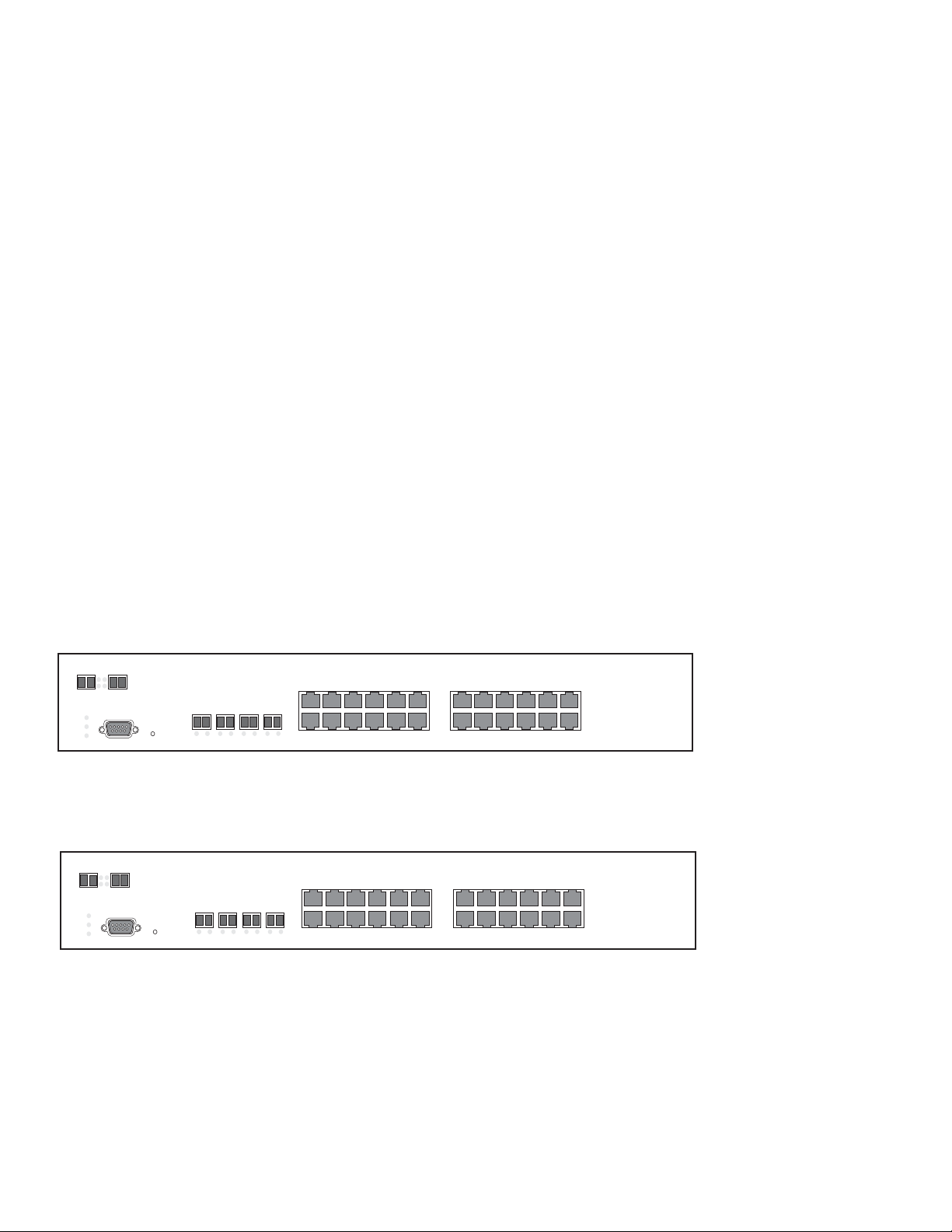
The following figure shows the front panel of the FESX424.
FIGURE 1 FESX424
The following figure shows the front panel of the FESX624. The FESX624E-PREM6 looks similar to the FESX624, except for the
model number on the front of the device.
FIGURE 2 FESX624
FESX624HF and FESX624HFE-PREM6
The FESX624HF and FESX624HFE-PREM6 have the following ports:
•
20 100/1000 Gigabit Ethernet fiber ports for mini-GBIC optical transceivers (also called Small Form Factor Pluggable (SFP)
Multisource Agreement (MSA)-compliant optical transceivers).
Brocade FastIron Edge X-Series Hardware Installation Guide 15
Part Number: 53-1002499-02

Console
PS2
PS1
Power
FastIron Edge X624HF
dge X624HF
Lnk/Act
1C 2C 3C 4C
Act
Lnk
25/49 26/50
12 34 56 78 910 11
12
1314 1516 1718 1920 2122 23
24
Lnk/Act
Consol e
PS 2
PS1
Po wer
1
2
FastIron Edge X648FastIron Edge X648
1F
Lnk
Act
Lnk
Act
2F
Lnk
Act
3F
Lnk
Act
4F
Lnk
Act
12341
2
5
6
1
2
7
89101112
151617181920212223
24
Act
Lnk
25/49 26/50
13
14
25
26
31
32302728
29
333435363738394041
42
47
48464344
45
Product Overview
Hardware features
•
Four combination Gigabit Copper or Fiber uplink ports:
•
The copper ports support 10/100/1000Base-T RJ-45 connectors.
•
The fiber ports support 100/1000 SFPs.
•
IPv6 (FESX6) devices optionally support two 10-Gigabit Ethernet uplink ports for 10-Gigabit Small Form Factor Pluggable
(XFP) MSA-compliant optical transceivers
Note that one port out of each pair of copper and fiber ports can be active at a time. For example, you can use either copper port 2 or fiber
port 2, but not both at the same time. You can use a combination of fiber and copper ports or all copper or all fiber ports, as needed. For
more information, refer to “Combination ports” on page 18.
The following figure shows the front panel of the FESX624HF. The FESX624HFE-PREM6 front panel looks similar to the FESX624HF,
except for the model number on the front panel.
FIGURE 3 FESX624HF front panel
FESX648 and FESX648E-PREM6
The FESXFESX648 and FESX648E-PREM6 have the following ports:
•
48 Copper ports that support 10/100/1000Base-T RJ-45 connectors
•
Four Gigabit Fiber uplink ports (1F – 4F) for mini-GBIC optical transceivers (also called Small Form Factor Pluggable (SFP)
Multisource Agreement (MSA)-compliant optical transceivers)
•
IPv6 (FESX6) devices optionally support two 10-Gigabit Ethernet uplink ports for 10-Gigabit Small Form Factor Pluggable
(XFP) MSA-compliant optical transceivers
Note that one port out of each pair of copper and fiber ports can be active at a time. For example, you can use either copper port 2 or fiber
port 2, but not both at the same time. You can use a combination of fiber and copper ports or all copper or all fiber ports, as needed (refer
to “Combination ports” on page 18).
The following figure shows the front panel of the FESX648. The FESX648E-PREM6 front panel looks similar to the FESX648, except
for the model number on the front panel.
FIGURE 4 FESX648 front panel
Control features
Each device’s front panel has the following control features:
16 Brocade FastIron Edge X-Series Hardware Installation Guide
Part Number: 53-1002499-02

Product Overview
Hardware features
•
Serial management interface (the port labeled Console)
•
Reset button
•
10/100/1000 ports with RJ-45 copper connectors
•
10/100/1000 ports with mini-GBIC slots for SFP MSA-compliant fiber transceivers
•
IPv6 (FESX6) devices optionally support two 10-Gigabit Ethernet uplink ports for 10-Gigabit Small Form Factor Pluggable
(XFP) MSA-compliant optical transceivers
Serial Management Interface (Console port)
The serial management interface enables you to configure and manage the device using a third-party terminal emulation application on a
directly connected PC. A straight-through EIA/TIA DB-9 serial cable (M/F) ships with the device. The serial management interface (the
port labeled Console) is located in the left corner of the front panel.
Reset button
The reset button allows you to restart the system without switching the power supplies off and on or using the CLI or Web Management
Interface. The button is located to the right of the serial management interface and is recessed to prevent it from being pushed
accidentally.
FastIron X Series network interfaces
The FastIron X Series compact switches support the network interfaces listed in Table 3 on page 20.
This section describes the port types in the FastIron X Series compact switches.
10/100/1000 Mbps ports
The 10/100/1000 ports on the FastIron X Series compact switches use auto-sensing and auto-negotiating to determine the speed (10
Mbps, 100 Mbps, or 1000 Mbps) and duplex mode (full-duplex or half-duplex) of the port at the other end of the link and adjust port
speed accordingly. 10/100/1000 ports on the devices support the interfaces listed in the section “Network interfaces” on page 20.
The 10/100 and Gigabit Copper ports support auto MDI or MDIX detection. For more information about this feature, refer to
"Configuring MDI or MDIX" in the <Italic>FastIron Configuration Guide.
100/1000 Mbps ports on Hybrid Fiber (HF) models
The 100/1000 ports on the hybrid fiber models (FESX424HF, FESX624HF, and FESX624HFE-PREM6) are configurable to support
the interfaces listed in the section “Network interfaces” on page 20.
Support for 100BaseFX
The hybrid fiber models support the following types of SFPs for 100BaseFX:
•
Multimode – maximum distance is 2 kilometers
•
Bidirectional singlemode – maximum distance is 10 kilometers
•
Long Reach (LR) – maximum distance is 40 kilometers
•
Intermediate Reach (IR) – maximum distance is 15 kilometers
To enable support for 100BaseFX, you must enter the CLI command link-config gig fiber 100-base-fx ethernet <portnum>. For CLI
command details, refer to the section “Enabling and Disabling Support for 100BaseFX” in the <Italic>FastIron Configuration Guide.
Brocade FastIron Edge X-Series Hardware Installation Guide 17
Part Number: 53-1002499-02

NOTE
Product Overview
Hardware features
Combination ports
One port out of each pair of copper and fiber ports can be active at a time. For example, you can use either copper port 2 or fiber port 2,
but not both at the same time. You can use a combination of fiber and copper ports or all copper or all fiber ports, as needed.
If you attach both the copper and fiber connectors for a port to the network, the fiber connectors take precedence over the copper
connectors. These ports support true media automatic detection, meaning the device selects the fiber or copper connector based on link
availability. If a fiber link cannot be established, the device selects the copper media.
10-Gbps ports
The 10-Gigabit Ethernet module on a FastIron X Series compact switch is optional. If one is installed on your device, it has either a oneor two-port optical interface for XFP MSA-compliant 10GBase-LR, 10GBase-SR, or 10GBase-ER – fiber cabling. If your device does
not include a 10-GbE module, you can optionally install one. Refer to “Installing or replacing a 10-Gigabit Ethernet module” on page 58.
For more details, follow these pointers:
•
IPv6 (FESX6) devices optionally support two 10-Gigabit Ethernet uplink ports for 10-Gigabit Small Form Factor Pluggable
(XFP) MSA-compliant optical transceivers
The 10-Gigabit Ethernet ports use 10-Gigabit Small Form Factor Pluggable (XFP) MSA-compliant transceivers.
The IPv6 10-GbE modules are supported in IPv6 compact switches only. Likewise, the IPv4 10-GbE modules are supported in
IPv4 compact switches only.
LEDs for FastIron X Series ports
The 10/100/1000 Mbps copper and fiber ports, and the 10-Gbps fiber ports on the FastIron X Series compact switches provide status
information using the LEDs listed in Table 2:
•
The copper ports use square LEDs located in the upper right and left corners of the upper Gigabit copper connector. The LEDs
are combined Lnk or Act LEDs. The LED on the left side is for the upper copper connector. The LED on the right side is for the
lower copper connector.
•
The Gigabit fiber connectors use the Lnk and Act LEDs located beneath the mini-GBIC slots for the fiber ports.
•
The 10-Gbps fiber connectors use the LEDs located next to the fiber ports.
LEDs for POE ports
The fiber and copper ports on the FESX424-POE provide status information using the LEDs listed in Table 2:
•
The 10/100/1000 copper ports (1 – 24) use the LEDs located on the top left and top right of the copper connectors. The
LEDs are combined Link or Activity (Lnk or Act) LEDs. The LED on the left side is for the upper fiber connector. The LED on the
right side is for the lower fiber connector.
•
The 10/100/1000 fiber ports (1F – 4F) use the LEDs located beneath the fiber connectors. The LED on the left side is the Lnk
LED, and the LED on the right side is the Act LED.
•
The POE ports (1 – 24) use the round LEDs located beneath the copper ports. The first (left-most) LED is for port 1, the second
LED is for port 2, the third LED is for port 3, etc.
TABLE 2 LEDs for FastIron X Series ports
LED Position State Meaning
10/100/1000 Copper Port LEDs
Left for upper copper connector
Right for lower copper connector
18 Brocade FastIron Edge X-Series Hardware Installation Guide
On The link is up.
Off The link is down.
Blinking The port is transmitting or receiving traffic
Part Number: 53-1002499-02

TABLE 2 LEDs for FastIron X Series ports (Continued)
LED Position State Meaning
10/100/1000 Fiber Port LEDs
Lnk Bottom left On The fiber port is connected.
Off No fiber port connection exists.
Act Bottom right On or blinking Traffic is being transmitted and received
Off No traffic is being transmitted on the fiber
100/1000 Fiber Port LEDs on the FESX424HF, FESX624HF, and FESX624HFE-PREM6
Left for upper copper
Right for lower copper connector
10-Gbps
Port LEDs
On The link is up.
Off The link is down.
Blinking The port is transmitting or receiving traffic
on the fiber port.
port.
Product Overview
Hardware features
Lnk Top right for left-most connector
Top left for right-most connector
Act Bottom right for left-most
connector
Bottom left for right-most
connector
POE Port LEDs
POE Left for upper port
Right for lower port
On The port is connected.
Off No fiber port connection exists.
On or Blinking Traffic is being transmitted and received
on the fiber port.
Off No traffic is being transmitted on the fiber
port.
On (Green) The port is enabled, a power-consuming
device has been detected, and the module
is supplying power to the device.
Off The port is not providing in-line power.
Port regions
Ports on the FastIron compact switches are grouped into regions. For a few features, such as port monitoring and unknown unicast
configurations, you will need to know the region to which a port belongs. However, for most features, a port’s region does not affect
configuration or operation of the feature. If a port’s region does affect configuration or operation of a feature, it is noted and described in
the appropriate feature section of this guide.
FastIron X Series compact switches with 24 ports:
•
Ports 1 – 12
•
Ports 13 – 24
•
Port 25 (optional 10-GbE uplink port)
•
Port 26 (optional 10-GbE uplink port)
FastIron X Series compact switches with 48 ports:
•
Ports 1 – 12
Brocade FastIron Edge X-Series Hardware Installation Guide 19
Part Number: 53-1002499-02

Product Overview
Hardware features
•
Ports 13 – 24
•
Port 25 – 36
•
Port 37 – 48
•
Port 49 (optional 10-GbE uplink port)
•
Port 50 (optional 10-GbE uplink port)
Network interfaces
Table 3 lists the network interfaces supported on the FastIron compact devices. For network interface and cabling specifications, refer to
Table 17 on page 69.
The output of the show media command displays the type of media installed in the ports.
TABLE 3 Network interfaces
Interface Show Media Description
1000Base-BX-D M-GBXD
1000Base-BX-U M-GBXU
1000Base-CWDM Cxxxx
1000Base-LHA M-LHA
1000Base-LHB M-LHB
1000Base-LX M-LX
1000Base-SX M-SX
1000Base-SX2 M-XR or M-SX2
1000Base-T M-C
100Base-BX M-FBXD or M-FBXU
100Base-FX M-FX, M-FXB1, or M-FXB2
100Base-FX-IR M-FX-IR
100Base-FX-LR M-FX-LR
100Base-FX-SR M-FX-SR
100Base-TX
10GBase-1310-MMF 1310-MMF
10GBase-CX4 XG-CX4
10GBase-ER XG-ER
10GBase-LR XG-LR
10GBase-SR XG-SR
10GBase-ZR XG-ZR
10GBase-ZRD XG-ZRD
2
1
M-TX
1. xxxx denotes the wavelength. For example, C1550.
2. Supported on copper ports only.
20 Brocade FastIron Edge X-Series Hardware Installation Guide
Part Number: 53-1002499-02

NOTE
NOTE
Product Overview
Hardware features
Power supplies
Each FastIron compact switch comes with one alternating-current (AC) or direct-current (DC) power supply, depending on how it was
ordered from the factory. All models have two power supply slots, enabling you to install a second power supply for redundancy.
Direct-current (DC) supplies are available for some devices, in which you can use any combination of AC and DC supplies in the same
device. The following table lists the power supplies that may be installed in a FastIron compact switch.
Table 4 and Table 5 show which Brocade power supply can be installed on each Brocade FastIron compact product.
You can interchange power supplies, but you must adhere to the compatibility matrix shown in the tables below.
Changes or modifications made to this device that are not expressly approved by the party responsible for compliance could void
the user's authority to operate the equipment.
TABLE 4 FastIron AC power supply compatibility matrix
Device RPS5
220 watts
1
2
RPS8
600 watts
RPS-X4
24
220
watts
RPS-X42
4-POE
600 watts
RPS-X44
8
600 watts
RPS-FGS
600 watts
FastIron Edge Switch Yes No Yes No No No
FastIron Edge Switch - Power
Over Ethernet
FastIron X Series with 24 ports Yes No Yes No No No
FastIron X Series with 48 ports No Yes No Yes Yes Yes
1. RPS5 = RPS-X424 = 220 watts
2. RPS8 = RPS-X424-POE = RPS-X448 = RPS-FGS = 600 watts
No Yes No No Yes Yes
TABLE 5 FastIron DC power supply compatibility matrix
Device RPS5DC
220 watts
FastIron Edge Switch Yes No No No No No
FastIron Edge Switch - Power
Over Ethernet
FastIron X Series with 24 ports No No Yes No No No
FastIron X Series with 48 ports No Yes No Yes Yes Yes
1. RPS5DC = RPSDC-X424 = 220 watts
2. RPS8DC = RPSDC-X424-POE = RPSDC-X448 = RPSDC-FGS = 600 watts
No Yes No No Yes Yes
1
RPS8DC
600 watts
2
RPSDC-X
424
220 watts
RPSDC-X
424-POE
600 watts
RPSDCX448
600
watts
RPSDC-FGS
600 watts
The power supplies can be swapped in or out of the device while the device is running. You can remove and insert a power supply without
opening the device. If the device contains non-POE redundant power supplies, you can remove one of the supplies without interrupting
operation. The remaining supply provides enough power for all the ports.
The following sections provide further details about the power supplies for the FastIron family of switches:
Brocade FastIron Edge X-Series Hardware Installation Guide 21
Part Number: 53-1002499-02
Product Overview
NOTE
Plastic Latch
AC Power
Connector
Power Supply (standard)
Hardware features
•
Power status LEDs are listed in Table 7 on page 26.
•
Hardware specifications for the power supplies are listed in Chapter 6, “Hardware Specifications”.
•
“About redundant power supplies and power supply failure” on page 23
POE power supply precautions
The following precautions apply to FastIron POE compact switches:
•
A device with dual power supplies may not provide redundancy, depending on how much power the POE ports are consuming.
For more information, refer to “What happens when a FastIron POE power supply fails” on page 23.
•
If your device has 48 ports and two power supplies, and the POE ports are consuming more than 480 watts of power, a single
power supply failure will cause both power supplies to shut down.
•
If your device has 48 ports and only one power supply, and each POE-enabled port needs 15.4 watts, then a maximum of 31
ports can supply power to connected devices.
•
If your device has 48 ports and only one power supply, and the power consuming devices connected to POE-enabled ports
consume a total of more than 480 watts of power, the power supply may shut down.
The system powers on as many POE ports as the power supplies can handle. The system calculates the maximum number
of POE ports it can support based on the number of power supplies installed. POE ports are enabled based on their priority
settings. Keep in mind that the system will reserve the maximum configured power per POE-enabled port, even if the POE
power-consuming device is drawing less power.
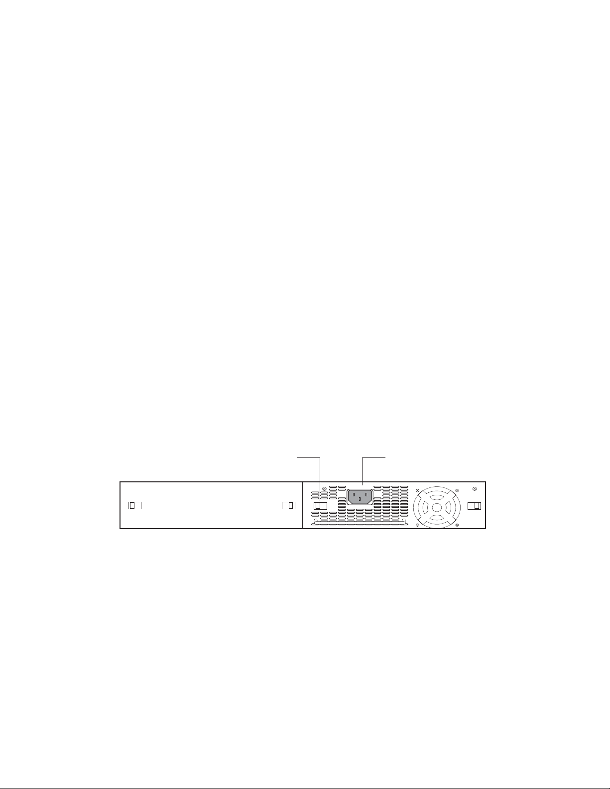
AC power supplies
Figure 5 shows a rear view of a FastIron Compact device containing one AC power supply. The power supply installed in your system
may vary from the one shown here, which does not have an ON or OFF switch.
FIGURE 5 AC power supply without ON or OFF switch
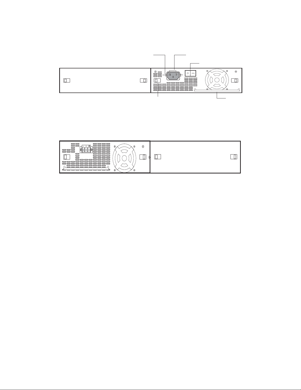
Figure 6 shows a rear view of a FastIron Compact device containing one AC power supply. The power supply installed in your system
may vary from the one shown here, which has an ON or OFF switch.
22 Brocade FastIron Edge X-Series Hardware Installation Guide
Part Number: 53-1002499-02
NOTE
Plastic Latch
AC Power
Connector
On/Off Switch
AC Cable
Retainer
Handle
FIGURE 6 AC power supply with ON or OFF switch
DC power supplies
Figure 7 shows a rear view of a FastIron Compact device containing one DC power supply.
FIGURE 7 RPS5DC power supply
Product Overview
Hardware features
About redundant power supplies and power supply failure
A FastIron compact switch with redundant power supplies can maintain full operation when one power supply fails. Power supply failure
can be a failure of the supply itself or the office power grid connected to the power supply.
What happens when a FastIron (non-POE) power supply fails
In a FastIron compact switch (non-POE) with redundant power supplies, power consumption is equally distributed between both power
supplies, within a certain percentage depending on power load or power supply type. However, when one power supply fails, the power
load is carried by the remaining power supply.
What happens when a FastIron POE power supply fails
A FastIron POE compact switch with dual power supplies may not provide redundancy, depending on how much power the POE ports
are consuming. In a POE device with redundant power supplies, power consumption is equally distributed (within a certain percentage
depending on power load or power supply type) between both power supplies. The power supplies provide power to both the system and
POE components. Therefore, a power supply failure can affect the operation of the entire device and not just POE ports.
If a switch has 48 ports and two power supplies, and the POE ports are consuming more than 480 watts of power, a single power
supply failure will cause both power supplies to shut down.
If a power supply fails and the system is left with less than the minimum required power, the remaining power supply will go into overload.
Several things can happen with a power supply failure in a FastIron POE switch. The output voltage of the remaining good power supply
will likely drop as it tries unsuccessfully to generate more power than it is capable of. The system will react to a drop in voltage by
increasing the current draw. POE ports will start to shut down due to over-current protection or under-voltage protection, whichever
occurs first. There is no particular order in which the POE ports will shut down, as this will occur in hardware and not in software.
After a power loss, if the system is left with less than the minimum number of power supplies required for normal operation, the system
will be left in an unknown state. At this point, manual recovery is required (i.e. restore power and power cycle the switch).
Brocade FastIron Edge X-Series Hardware Installation Guide 23
Part Number: 53-1002499-02

Product Overview
Hardware features
Cooling system and fans
This section describes the fans in the FastIron compact switches.
FastIron X Series fans
The FastIron X Series cooling fans cool the CPU, main memory, and voltage regulators. The fans use either a push or pull configuration to
move the air from the left side of the device to the right side of the device.
The fans in the 24-port FastIron X Series switches operate at a single speed and do not support multiple fan speeds.
The fans in the 48-port FastIron X Series switches include two three-speed fans that operate at low speed, then adjust based on the
ambient temperature and configured or default temperature thresholds. Both fans operate simultaneously at the same speed. If one fan
fails, it does not affect the operation of the other fan.
The fans can operate at speeds of low, medium, and high. The system uses a fan speed switch and a default or configured temperature
threshold associated with it to determine at which speed the fan should operate. If desired, you can change the settings of the temperature
thresholds associated with fan speed switches. For more information, refer to “Managing temperature settings and fan speed on FastIron
X Series compact switches” on page 11.
24 Brocade FastIron Edge X-Series Hardware Installation Guide
Part Number: 53-1002499-02

Installing a FastIron Compact Switch
Unpacking a system
The procedures in this guide are for qualified service personnel.
The Brocade systems ship with all of the following items. Please review the list below and verify the contents. If any items are missing,
please contact the place of purchase.
Package contents
•
Brocade Communications Systems, Inc. FastIron compact switch
•
115V AC power cable (for AC sourced devices)
•
Rack mount brackets and mounting screws
•
Warranty card
General requirements
To manage the system, you need the following items for serial connection to the switch or router:
•
A management station, such as a PC running a terminal emulation application.
•
A straight-through EIA or TIA DB-9 serial cable (F/F). The serial cable can be ordered separately from Brocade
Communications Systems, Inc.. If you prefer to build your own cable, refer to the pinout information in “Attaching a PC or
terminal” on page 36.
You use the serial connection to perform basic configuration tasks including assigning an IP address and network mask to the system.
This information is required for managing the system using the Web Management Interface or Brocade Network Advisor or using the CLI
through Telnet.
Do not use the handles on the power supply units to lift or carry a Brocade device.
Summary of installation tasks
Follow the steps listed below to install your FastIron compact switch. Details for each of the steps highlighted below are provided in this
chapter and in the following chapter.
Brocade FastIron Edge X-Series Hardware Installation Guide 25
Part Number: 53-1002499-02

Installing a FastIron Compact Switch
Installation precautions
TABLE 1 Summary of installation tasks
Task
Number
Task Where to Find More Information
1 Ensure that the physical environment that will host the device has
the proper cabling and ventilation.
2 Optionally insert a second or redundant power supply. If you need
to install a power supply, it may be easier to install it before
mounting the device, although the power supplies are “hot
swappable”, and can be installed or removed after the device is
mounted and powered-on.
NOTE: CAUTION: Remove the power cord from a power supply
before you install it in or remove it from the device.
Otherwise, the power supply or the device could be
damaged as a result. (The device can be running while a
power supply is being installed or removed, but the power
supply itself should not be connected to a power source.)
4 Install the Brocade device on a desktop, in an equipment rack, or
on the wall.
5 Once the device is physically installed, plug the device into a
nearby power source that adheres to the regulatory requirements
outlined in this guide.
6 Verify that the system LEDs are registering the proper LED state
after power-on of the system.
7 Attach a terminal or PC to the Brocade device. This will enable
you to configure the device through the Command Line Interface
(CLI).
8 No default password is assigned to the CLI. For additional access
security, assign a password.
9 Before attaching equipment to the device, you need to configure
an interface IP address to the subnet on which it will be located.
Initial IP address configuration is performed using the CLI with a
direct serial connection. Subsequent IP address configuration can
be performed using the Web Management Interface.
10 Once you power on the device and assign IP addresses, the
system is ready to accept network equipment.
11 Test IP connectivity to other devices by pinging them and tracing
routes.
12 Continue configuring the device using the CLI or the Web
Management Interface. You also can use Brocade Network
Advisor to manage the device. Refer to the user guides for
<Italic>Brocade Network Advisor for information.
13 Secure access to the device. <Italic>FastIron Configuration
“Preparing the installation site” on
page 29
“Installing a redundant power
supply” on page 30
“Installing the device” on page 32
“Powering on the system” on
page 34
“Verifying proper operation” on
page 35
“Attaching a PC or terminal” on
page 36
“Assigning permanent passwords”
on page 39
“Configuring IP addresses” on
page 41
“Connecting network devices” on
page 45
“Testing connectivity” on page 49
<Italic>FastIron Configuration
Guide (for FastIron X Series
compact devices)
Guide (for FastIron X Series
compact devices)
Installation precautions
Follow these precautions when installing a Brocade device.
26 Brocade FastIron Edge X-Series Hardware Installation Guide
Part Number: 53-1002499-02
General precautions
All fiber-optic interfaces use Class 1 lasers.
Do not install the device in an environment where the operating ambient temperature might exceed 40o C
(104o F).
Make sure the air flow around the front, sides, and back of the device is not restricted.
Installing a FastIron Compact Switch
Installation precautions
Never leave tools inside the chassis.
Lifting precautions
Make sure the rack or cabinet housing the device is adequately secured to prevent it from becoming
unstable or falling over.
Do not use the handles on the power supply units to lift or carry a Brocade device.
Mount the devices you install in a rack or cabinet as low as possible. Place the heaviest device at the
bottom and progressively place lighter devices above.
Power precautions
Use a separate branch circuit for each AC power cord, which provides redundancy in case one of the
circuits fails.
Brocade FastIron Edge X-Series Hardware Installation Guide 27
Part Number: 53-1002499-02

Installing a FastIron Compact Switch
Installation precautions
Ensure that the device does not overload the power circuits, wiring, and over-current protection. To
determine the possibility of overloading the supply circuits, add the ampere (amp) ratings of all devices
installed on the same circuit as the device. Compare this total with the rating limit for the circuit. The
maximum ampere ratings are usually printed on the devices near the input power connectors.
All devices with DC power supplies are intended for installation in restricted access areas only. A
restricted access area is where access can be gained only by service personnel through the use of a
special tool, lock and key, or other means of security, and is controlled by the authority responsible for the
location.
For the DC input circuit to a FESX or FWSX (DC power supply part number RPS5DC and RPS-X424-DC),
make sure there is a 10-amp listed circuit breaker, minimum -48VDC, double pole, on the input to the
terminal block. The input wiring for connection to the product should be Listed copper wire, 14 AWG,
marked VW-1, and rated 90 degrees Celsius.
For the DC input circuit to the system (DC power supply part number RPSDC-X424-POE), make sure there
is a Listed 30 amp circuit breaker, minimum -48Vdc, double pole, on the input to the terminal block. The
input wiring for connection to the product should be Listed copper wire, 10 AWG, marked VW-1, and rated
minimum 90 degrees celcius.
Make sure you insert the power supply right-side up. It is possible to insert the supply upside down,
although the supply will not engage with the power backplane when upside down. The power supply is
right-side up when the power connector is on the left and the fan vent is on the right.
28 Brocade FastIron Edge X-Series Hardware Installation Guide
Part Number: 53-1002499-02
Installing a FastIron Compact Switch
Preparing the installation site
Remove the power cord from a power supply before you install it in or remove it from the device.
Otherwise, the power supply or the device could be damaged as a result. (The device can be running
while a power supply is being installed or removed, but the power supply itself should not be connected to
a power source.)
Disconnect the power cord from all power sources to completely remove power from the device.
Make sure to choose the appropriate circuit device depending on the number of AC power supplies
installed in the chassis. The minimum current draw for the system is one AC power supply.
Power supplies are hot swappable. However, Brocade recommends that you disconnect the power supply
from AC power before installing or removing the supply. The device can be running while a power supply
is being installed or removed, but the power supply itself should not be connected to a power source.
Otherwise, you could be injured or the power supply or other parts of the device could be damaged.
Make sure that the power source circuits are properly grounded, then use the power cord supplied with
the device to connect it to the power source.
If the installation requires a different power cord than the one supplied with the device, make sure you
use a power cord displaying the mark of the safety agency that defines the regulations for power cords in
your country. The mark is your assurance that the power cord can be used safely with the device.
Preparing the installation site
Cabling infrastructure
Ensure that the proper cabling is installed in the site. Refer to Chapter 6, “Hardware Specifications” or www.brocade.com for a summary of
supported cabling types and their specifications.
Brocade FastIron Edge X-Series Hardware Installation Guide 29
Part Number: 53-1002499-02
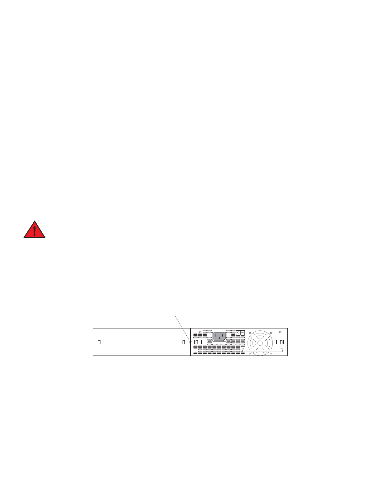
Power Supply locking screw
Installing a FastIron Compact Switch
Installing a redundant power supply
Installation location
Before installing the device, plan its location and orientation relative to other devices and equipment. Allow at least 3 inches of space at the
front of the device for the twisted-pair, fiber-optic, and power cabling. Also, allow a minimum of 3 inches of space between the sides and
the back of the device and walls or other obstructions.
Installing a redundant power supply
The FastIron Compact device ships with one AC or DC power supply. If desired, you can install a second supply for redundancy. For
more information about power supply redundancy, refer to “About redundant power supplies and power supply failure” on page 23.
If you need to install a redundant power supply, it may be easier to install it before mounting the device, although the power supplies are
“hot swappable” and can be installed or removed after the device is mounted and powered on.
This section provides the following procedures:
•
Installing a redundant AC power supply – “Installing an AC power supply” on page 30
•
Installing a redundant DC power supply – “Installing a DC power supply” on page 31
Installing an AC power supply
Before beginning the installation, refer to the precautions in “Power precautions” on page 27.
Use the following procedures for AC power supplies in FastIron compact devices. Refer to “Power supplies” on page 21 for a list of which
power supplies are supported in each device, and for illustrations showing power supply placement in the Brocade devices.
To install an AC power supply, complete the following steps.
1. If necessary, remove the power supply locking screw located in the center rear of the device (illustrated below).
2. If the empty power supply bay has a cover plate, press inward on the two latches near the edges of the cover plate to unlock the plate, then remove the plate.
3. Remove the power supply from its packaging.
4. With one hand, hold the bar on the front panel of the power supply. With the other hand, support the underside of the power
supply, and insert the power supply into the empty power supply slot. Press until the supply is completely in the slot, so that the
connectors on the back of the supply are fully engaged with the pins on the power backplane.
30 Brocade FastIron Edge X-Series Hardware Installation Guide
Part Number: 53-1002499-02